JP7039242B2 - Image projection device, its control method, and program - Google Patents
Image projection device, its control method, and program Download PDFInfo
- Publication number
- JP7039242B2 JP7039242B2 JP2017199558A JP2017199558A JP7039242B2 JP 7039242 B2 JP7039242 B2 JP 7039242B2 JP 2017199558 A JP2017199558 A JP 2017199558A JP 2017199558 A JP2017199558 A JP 2017199558A JP 7039242 B2 JP7039242 B2 JP 7039242B2
- Authority
- JP
- Japan
- Prior art keywords
- control value
- control
- light
- image
- unit
- Prior art date
- Legal status (The legal status is an assumption and is not a legal conclusion. Google has not performed a legal analysis and makes no representation as to the accuracy of the status listed.)
- Active
Links
Images


Classifications
-
- Y—GENERAL TAGGING OF NEW TECHNOLOGICAL DEVELOPMENTS; GENERAL TAGGING OF CROSS-SECTIONAL TECHNOLOGIES SPANNING OVER SEVERAL SECTIONS OF THE IPC; TECHNICAL SUBJECTS COVERED BY FORMER USPC CROSS-REFERENCE ART COLLECTIONS [XRACs] AND DIGESTS
- Y02—TECHNOLOGIES OR APPLICATIONS FOR MITIGATION OR ADAPTATION AGAINST CLIMATE CHANGE
- Y02B—CLIMATE CHANGE MITIGATION TECHNOLOGIES RELATED TO BUILDINGS, e.g. HOUSING, HOUSE APPLIANCES OR RELATED END-USER APPLICATIONS
- Y02B20/00—Energy efficient lighting technologies, e.g. halogen lamps or gas discharge lamps
- Y02B20/40—Control techniques providing energy savings, e.g. smart controller or presence detection
Landscapes
- Projection Apparatus (AREA)
- Circuit Arrangement For Electric Light Sources In General (AREA)
- Transforming Electric Information Into Light Information (AREA)
- Controls And Circuits For Display Device (AREA)
Description
本発明は、画像投影装置及びその制御方法、並びにプログラムに関し、特に照明モードと投影モードの切り替えと、各モードにおける照度を調整する画像投影装置及びその制御方法、並びにプログラムに関する。 The present invention relates to an image projection device and its control method, and a program, and more particularly to an image projection device for switching between an illumination mode and a projection mode, and an image projection device for adjusting the illuminance in each mode, and a program thereof.
従来より、白熱灯等を用いた照明装置の明るさを調整するためのロータリー式やスライド式のつまみを有する調光装置がある。この調光装置ではつまみの設定位置に応じて供給する電源の電圧波形を制御することにより、照明装置の白熱灯に与える電力を制御して明るさを調整する。 Conventionally, there is a dimming device having a rotary type or a slide type knob for adjusting the brightness of a lighting device using an incandescent lamp or the like. In this dimming device, the voltage waveform of the power supply supplied according to the setting position of the knob is controlled to control the power applied to the incandescent lamp of the lighting device to adjust the brightness.
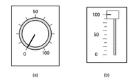
図2は、従来の調光装置におけるつまみの一例であり、図2(a)はロータリー式のつまみ、図2(b)はスライド式のつまみである。それぞれつまみの設定位置は、ユーザが回転やスライドすることにより変更され、白熱灯はその変更されたつまみの設定位置に応じた明るさに調光される。 2A and 2B are examples of knobs in a conventional dimming device, FIG. 2A is a rotary type knob, and FIG. 2B is a slide type knob. The setting position of each knob is changed by the user rotating or sliding, and the incandescent lamp is dimmed to the brightness according to the changed knob setting position.
また従来の調光装置には、図4(a)や図4(b)のように照明のONとOFFを制御するスイッチが付加されているものもあり、広く使われている。 Further, some conventional dimming devices are provided with a switch for controlling ON / OFF of lighting as shown in FIGS. 4 (a) and 4 (b), and are widely used.
一方、画像や映像を投影する画像投影装置に照明機能を持たせ、照明装置と画像投影装置を兼用する照明兼用プロジェクタ(以降、単に「プロジェクタ」と呼ぶ。)がある(例えば、特許文献1参照)。このようなプロジェクタは動作モードとして、画像投影機能を使う投影モードと照明機能を使う照明モードを有し、照明モード時には投影面に一様な光を投射する。 On the other hand, there is a projector for both lighting (hereinafter, simply referred to as "projector") in which an image projection device for projecting an image or a video has a lighting function and the lighting device and the image projection device are used in combination (see, for example, Patent Document 1). ). Such a projector has a projection mode that uses an image projection function and an illumination mode that uses an illumination function as operation modes, and projects uniform light onto the projection surface in the illumination mode.
特許文献1では、入力された情報に応じて照明モードと投影モードの二つの動作モードの切り替えを実現している。 In Patent Document 1, switching between two operation modes, an illumination mode and a projection mode, is realized according to the input information.
また、入力された画像や映像に応じて光源の光量を決定するプロジェクタも知られている(例えば、特許文献2参照)。 Further, a projector that determines the amount of light of a light source according to an input image or video is also known (see, for example, Patent Document 2).
しかしながら、特許文献1,2で記載されるプロジェクタはいずれも照明モードにおいて、従来の照明装置が具備するような調光機能は具備していない。よって、特許文献1,2で記載されるプロジェクタでは、従来の照明装置と同様の操作で調光を行いつつ、動作モードの切り替えもスムーズに行いたいというユーザの要望を満たすことができない。このため、これらのプロジェクタを照明装置として使うには利便性が低いという課題があった。 However, none of the projectors described in Patent Documents 1 and 2 has a dimming function that a conventional lighting device has in the lighting mode. Therefore, the projectors described in Patent Documents 1 and 2 cannot satisfy the user's desire to smoothly switch the operation mode while performing dimming by the same operation as the conventional lighting device. Therefore, there is a problem that it is not convenient to use these projectors as a lighting device.
上記点を鑑み、本発明は、従来の照明装置と同様の操作で調光を可能とする画像投影装置及びその制御方法、並びにプログラムを提供することを目的とする。さらには、本発明は、従来の照明装置と同様の操作で動作モードの切り替えもスムーズに行うことができる画像投影装置及びその制御方法、並びにプログラムを提供することを目的とする。 In view of the above points, it is an object of the present invention to provide an image projection device capable of dimming by the same operation as a conventional lighting device, a control method thereof, and a program. Furthermore, it is an object of the present invention to provide an image projection device, a control method thereof, and a program capable of smoothly switching an operation mode by the same operation as that of a conventional lighting device.
本発明の請求項1に係る画像投影装置は、位置又は回転角に応じて制御値を出力する操作部材と、光を投射する出力手段と、前記操作部材の位置又は回転角に応じて前記出力手段を制御する制御手段と、を有し、前記制御手段は、前記操作部材の前記位置又は前記回転角が第1の範囲にある場合に、前記出力手段を、一様な光を出力する照明モードとし、その光量が前記制御値が大きいほど大きくなるように制御し、前記操作部材の前記位置又は前記回転角が第2の範囲にある場合に、前記出力手段を、画像を投影する投影モードとし、その光量が前記制御値が大きいほど小さくなるように制御することを特徴とする。 The image projection device according to claim 1 of the present invention includes an operating member that outputs a control value according to a position or an angle of rotation , an output means that projects light, and the output according to the position or the angle of rotation of the operating member. The control means includes a control means for controlling the means, and the control means illuminates the output means to output uniform light when the position or the rotation angle of the operation member is in the first range. A projection mode in which the amount of light is controlled to increase as the control value increases , and the output means projects an image when the position or rotation angle of the operating member is in the second range. The light amount is controlled so that the larger the control value is, the smaller the amount of light is .
本発明によれば、従来の照明装置と同様の操作で調光を可能とする。 According to the present invention, dimming can be performed by the same operation as that of a conventional lighting device.
以下、図面を参照して本発明の実施例を詳細に説明するが、この発明は以下の実施の形態に限定されない。なお、以下の実施の形態は特許請求の範囲に係る発明を限定するものでなく、また実施の形態で説明されている特徴の組み合わせの全てが発明の解決手段に必須のものとは限らない。 Hereinafter, embodiments of the present invention will be described in detail with reference to the drawings, but the present invention is not limited to the following embodiments. It should be noted that the following embodiments do not limit the invention according to the claims, and not all combinations of features described in the embodiments are essential for the means for solving the invention.
また、以下の実施形態において説明される各機能ブロックは必ずしも個別のハードウェアである必要はない。すなわち、例えばいくつかの機能ブロックの機能は、1つのハードウェアにより実行されても良い。また、いくつかのハードウェアの連係動作により1つの機能ブロックの機能または、複数の機能ブロックの機能が実行されても良い。また、各機能ブロックの機能は、CPUがメモリ上に展開したコンピュータプログラムにより実行されても良い。 Further, each functional block described in the following embodiments does not necessarily have to be individual hardware. That is, for example, the functions of some functional blocks may be executed by one piece of hardware. Further, the function of one functional block or the function of a plurality of functional blocks may be executed by the linked operation of some hardware. Further, the function of each functional block may be executed by a computer program expanded on the memory by the CPU.
本発明に係る投影装置の一例として、透過型液晶パネルを用いた表示機能と照明機能を兼ねる液晶プロジェクタについて以下説明する。しかし、本発明に係る画像投影装置は、表示デバイスとして透過型液晶パネルを用いた液晶プロジェクタに限らず、DLP、LCOS(反射型液晶)パネルなどの表示デバイスを用いたプロジェクタであってもよい。また、液晶プロジェクタには、単板式、3板式などが一般に知られているが、どちらの方式であっても良い。 As an example of the projection device according to the present invention, a liquid crystal projector having both a display function and a lighting function using a transmissive liquid crystal panel will be described below. However, the image projection device according to the present invention is not limited to a liquid crystal projector using a transmissive liquid crystal panel as a display device, and may be a projector using a display device such as a DLP or LCOS (reflection type liquid crystal) panel. Further, although a single-plate type, a three-plate type, or the like is generally known as the liquid crystal projector, either method may be used.
本実施例の液晶プロジェクタは、投影モードと照明モードのいずれかで動作する照明兼用プロジェクタである。投影モード時には、投影するべき画像(以下「投影用画像」という。)に応じて液晶素子の光の透過率を制御して、液晶素子を透過した光源からの光をスクリーンに投影することで、投影用画像をユーザに提示する。また、照明モードでの動作中は、照明用画像を投影することにより照明機能を提示する。 The liquid crystal projector of this embodiment is a projector for both lighting that operates in either a projection mode or a lighting mode. In the projection mode, the transmittance of the light of the liquid crystal element is controlled according to the image to be projected (hereinafter referred to as "projection image"), and the light from the light source transmitted through the liquid crystal element is projected onto the screen. Present the projection image to the user. Further, during operation in the illumination mode, the illumination function is presented by projecting an image for illumination.
以下、このような液晶プロジェクタである画像投影装置100について説明する。
Hereinafter, the
図1は、本発明に係る画像投影装置100のハードウェア構成を示すブロック図である。
FIG. 1 is a block diagram showing a hardware configuration of the
画像投影装置100は、CPU110、ROM112、RAM111、操作部113、画像入力部120、画像処理部140を有する。また、画像投影装置100は、さらに、光変調素子駆動部150、光変調素子170R,170G,170B、光源制御部130、光源160、色分離部161、色合成部180、投影光学制御部182、投影光学系181を有する。また、画像投影装置100は、さらに、通信部114を有する。
The
CPU110は、画像投影装置100の各動作ブロックを制御し、ROM112にはCPU110の処理手順を記述した制御プログラムを記憶し、RAM111は、ワークメモリとして一時的に制御プログラムやデータを格納する。また、ROM112には照明モード時の投影画像データが格納されている。CPU110は、通信部114より受信した静止画データや動画データを一時的に記憶し、ROM112に記憶されたプログラムを用いて、それぞれの画像や映像を再生したりすることもできる。
The
操作部113は、ユーザの指示を受け付け、CPU110に指示信号を送信するものであり、例えば、スイッチやダイヤルなどからなる。また、操作部113は、例えば、リモコンからの信号を受信する信号受信部(赤外線受信部など)で、受信した信号に基づいて所定の指示信号をCPU110に送信するものであってもよい。また、CPU110は、操作部113や、通信部114から入力された制御信号を受信して、画像投影装置100の各動作ブロックを制御する。
The
画像入力部120は、外部装置から送信される画像信号を受信するものである。ここで、外部装置とは、画像信号を出力できるものであれば、パーソナルコンピュータ、カメラ、携帯電話、スマートフォン、ハードディスクレコーダ、ゲーム機など、どのようなものであってもよい。また、画像入力部120は、USBフラッシュメモリやSDカードのようなメディアが装着されたときに、そのメディアに記録された画像を読み込むこともできる。
The
画像処理部140は、画像入力部120から受信した画像信号にフレーム数、画素数、画素値、画像形状などの変更処理を施して、光変調素子駆動部150に送信するものであり、例えば画像処理用のマイクロプロセッサからなる。なお、画像処理部140は、専用のマイクロプロセッサである必要はなく、例えば、ROM112に記憶されたプログラムによって、CPU110が画像処理部140と同様の処理を実行しても良い。画像処理部140は、フレーム間引き処理、フレーム補間処理、解像度変換(スケーリング)処理、歪み補正処理(キーストン補正処理)、輝度補正処理、色補正処理といった機能を実行することが可能である。また、画像処理部140は、所望のテストパターン画像を生成して光変調素子駆動部150に送信することもできる。また、画像処理部140は、画像入力部120から受信した画像信号以外にも、CPU110によって再生された画像や映像に対して前述の変更処理を施すこともできる。
The
光変調素子駆動部150は、画像処理部140から出力される画像信号に基づいて、光変調素子170R,170G,170Bを構成する各画素の液晶に印可する電圧を制御して、光変調素子170R,170G,170Bの透過率を調整する。
The light modulation
光変調素子170Rは、赤色に対応する液晶素子であって、光源160から出力された光のうち、色分離部161で赤色(R)、緑色(G)、青色(B)に分離された光のうち、赤色の光の透過率を調整するためのものである。光変調素子170Gは、緑色に対応する光変調素子であって、光源160から出力された光のうち、色分離部161で赤色(R)、緑色(G)、青色(B)に分離された光のうち、緑色の光の透過率を調整するためのものである。光変調素子170Bは、青色に対応する液晶素子であって、光源160から出力された光のうち、色分離部161で赤色(R)、緑色(G)、青色(B)に分離された光のうち、青色の光の透過率を調整するためのものである。
The
光源制御部130は、光源160のオン/オフを制御や光量の制御をするものであり、制御用のマイクロプロセッサからなる。また、光源制御部130は、専用のマイクロプロセッサである必要はなく、例えば、ROM112に記憶されたプログラムによって、CPU110が光源制御部130と同様の処理を実行しても良い。また、光源160は、不図示のスクリーンに画像を投影するための光を出力するものであり、例えば、ハロゲンランプ、キセノンランプ、高圧水銀ランプなどであっても良い。また、色分離部161は、光源160から出力された光を、赤色(R)、緑色(G)、青色(B)に分離するものであり、例えば、ダイクロイックミラーやプリズムなどからなる。なお、光源160として、赤色(R)、緑色(G)、青色(B)の各色に対応するLED等を使用する場合には、色分離部161は不要である。
The light
また、色合成部180は、光変調素子170R,170G,170Bを透過した赤色(R)、緑色(G)、青色(B)の光を合成するものであり、例えば、ダイクロイックミラーやプリズムなどからなる。そして、色合成部180により赤色(R)、緑色(G)、青色(B)の成分を合成した光は、投影光学系181に送られる。このとき、光変調素子170R,170G,170Bは、画像処理部140から入力された画像に対応する光の透過率となるように、光変調素子駆動部150により制御されている。そのため、色合成部180により合成された光は、投影光学系181によりスクリーンに投影されると、画像処理部140で画像処理された画像に対応する画像がスクリーン上に表示されることになる。
Further, the
投影光学制御部182は、投影光学系181を制御するものであり、制御用のマイクロプロセッサからなる。また、投影光学制御部182は、専用のマイクロプロセッサである必要はなく、例えば、ROM112に記憶されたプログラムによって、CPU110が投影光学制御部182と同様の処理を実行しても良い。また、投影光学系181は、色合成部180から出力された合成光をスクリーンに投影するためのものであり、複数のレンズ、レンズ駆動用のアクチュエータからなる。レンズをアクチュエータにより駆動することで、投影画像の拡大、縮小、焦点調整などを行うことができる。
The projection
通信部114は、外部機器からの制御信号や静止画データ、動画データなどを受信するためのものであり、例えば、無線LAN、有線LAN、USB、Bluetooth(登録商標)などであってよく、通信方式を特に限定するものではない。また、画像入力部120の端子が、例えばHDMI(登録商標)端子であれば、その端子を介してCEC通信を行うものであっても良い。ここで、外部装置は、画像投影装置100と通信を行うことができるものであれば、パーソナルコンピュータ、カメラ、携帯電話、スマートフォン、ハードディスクレコーダ、ゲーム機、リモコンなど、どのようなものであってもよい。
The
なお、画像処理部140、光変調素子駆動部150、光源制御部130、及び投影光学制御部182は、これらの各ブロックと同様の処理を行うことのできる単数または複数のマイクロプロセッサあっても良い。または、例えば、ROM112に記憶されたプログラムによって、CPU110が各ブロックと同様の処理を実行しても良い。
The
制御値設定部115はユーザ操作に応じて光量と動作モードに関する制御値の設定手段であり、例えばロータリーエンコーダー(図2(a))やリニアエンコーダー(図2(b))等からなるつまみを有する。これらのつまみの形状や動作は従来の白熱灯の調光装置と同様である。尚、このつまみへのユーザ操作に応じて上記制御値の設定が可能であれば、制御値設定部115の形状や動作は図2に示すものに限定されるものではない。例えば、タッチパネルからなる操作部113が制御値設定部115を兼ねてもよい。この場合、例えば、操作部113における制御値設定画面の表示時に、タッチパネルの所定位置へのユーザによるフリック操作やスライド操作に応じて制御値が設定される。
The control
本発明の画像投影装置100における投影モードについては以上に述べたとおりである。ここで本発明の画像投影装置100における照明モードについて説明する。
The projection mode in the
ユーザにより操作部113もしくは不図示のリモコンにより、照明モードが選択された場合には、CPU110は画像処理部140に対して照明用画像として一様な画像を出力するように命令する。一様な画像とは、RGBの各画素値がフレーム内で同じ値である投影画像データである。尚、照明モードの用途によっては出力する画像は一様の画像でなくても良い。また、ROM112に照明モード用の画像データを格納しておき、それを読み出しても良い。その場合は、照明モード用の画像データを光変調素子駆動部150に出力し、光変調素子170R,170G,170Bで変調して投影光学系181より投影することにより、画像投影装置100の照明モードとして実現する。
When the lighting mode is selected by the user using the
また画像投影装置100において照明機能を実現する別の方法として、不図示の光学系において、光変調素子170R,170G,170Bを通さずに光源160の光を直接投影光学系181から投影しても良い。
Further, as another method for realizing the illumination function in the
また別の方法として、CPU110は投影面に対して投影光学系181の焦点を結像位置からずらして投影画像をぼかしたり、もしくは投影光学系181の前又は後に不図示の光を拡散する光拡散手段を設置したり、もしくはこれらを組み合わせても良い。この場合、照明モードにおいて部屋全体を照明することができるようになる。
Alternatively, the
以上のような方法で、照明用の画像もしくは光源160からの光を色分離部161から色合成部180までの処理系を経ないで投影光学系181から投影させることにより、画像投影装置100を照明装置として使うことができる。
By the above method, the
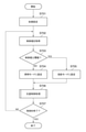
以下、図5のフローチャートを用いて本実施例の動作処理について説明する。 Hereinafter, the operation processing of this embodiment will be described with reference to the flowchart of FIG.
本実施例では、画像投影装置100が投影する光量についてのみ制御が行われ、動作モードの制御や、動作モードの制御に伴う映像信号処理系の制御については行わない。また、本施例において動作モードの切り替えはユーザ操作に応じて行われる。
In this embodiment, the control is performed only on the amount of light projected by the
まず、ステップS501では、制御部であるCPU110が画像投影装置100の動作モードや明るさの初期設定を行う。
First, in step S501, the
ステップS502では、制御値設定部115においてユーザ操作(例えば、ユーザによる制御値設定部115上のつまみの操作)により設定された制御値を、制御部であるCPU110が取得する。CPU110は定期的に制御値設定部115にアクセスする。もしくは制御値設定部115において制御値が更新された場合にCPU110に対して割り込み信号を送信し、CPU110は割り込み信号に応じて制御値設定部115から制御値を読み出す。制御値は制御値設定部115におけるつまみの位置に応じた絶対値であり、例えば0から100までの値を出力する。制御値は制御値設定部115上のつまみの位置に応じた値であればこの値には限定しない。
In step S502, the
画像投影装置100の光量を制御する手段は調光手段である制御値設定部115だけでなく、例えば不図示のリモコンの場合もある。その場合には、CPU110は不図示の受信部(受信手段)を通じてリモコンから制御値を取得する。また、タッチパネルからなる操作部113が制御値設定部115を兼ねる場合は、操作部113における制御値設定画面の表示時に、タッチパネルの所定位置へのユーザによるフリック操作やスライド操作に応じて設定された制御値をCPU110は取得する。
The means for controlling the amount of light of the
制御値設定部115で設定される制御値は絶対値であるが、不図示のリモコンにおいては、光量を上げるボタンと下げるボタン持つ場合には、リモコンから送信する制御値は相対値となる。例えば一回光量を上げるボタンを押せば+10%と言うように制御値を送信する。
The control value set by the control
ステップS503では、CPU110は取得した制御値に応じた光量となるように光源160を制御する光量制御処理を行う。
In step S503, the
具体的には、CPU110は光源制御部130に対して送信する相対値である光量制御値を算出し、光源制御部130に送信する。光源制御部130はその送信された光量制御値に応じて光源160の光量を制御する。ここで光量制御値は以下のように算出される。CPU110が制御値設定部115から絶対値である制御値を新たに取得した場合には、前回取得した制御値に対する今回取得した制御値の相対値を算出して、その相対値を前回算出した光量制御値に加算した値を新たな光量制御値として算出する。またリモコン等から現在の明るさを上げるか下げるかといった相対値である制御値を取得した場合には、そのままその制御値を前回算出した光量制御値に加算した値を新たな光量制御値として算出する。尚、本実施例では、光量制御値の算出は、CPU110が行っているが算出部を別途設けてもよい。
Specifically, the
光量制御値は、光源制御部130を制御する値である。光源制御部130は、光量制御値が0のときには光源160を消灯させ、すなわち、0%の光量となるように制御し、50のときには50%の光量とし、100のときには100%の光量となるように制御する。
The light amount control value is a value that controls the light
以下、図9において、ステップS503の光量制御処理についてより詳細に説明する。 Hereinafter, in FIG. 9, the light amount control process in step S503 will be described in more detail.
まず、ステップS901では、取得した制御値が絶対値であるかどうか判断する。本実施例においては、制御値設定部115から取得される場合の制御値は絶対値であり、リモコンから取得される場合の制御値は相対値である。取得した制御値が絶対値のときはステップS902に移る。制御値が絶対値でなかったときはステップS905に移る。
First, in step S901, it is determined whether or not the acquired control value is an absolute value. In this embodiment, the control value when acquired from the control
ステップS902では、過去の制御値設定部115の制御値をRAM111から読み出す。
In step S902, the control value of the past control
ステップS903では、ステップS502で取得した現在の制御値でRAM111の過去の制御値を更新する。
In step S903, the past control value of the
ステップS904では、ステップS502で取得した現在の制御値の、ステップS902で読み出した過去の制御値に対する相対値を算出し、その相対値を光量制御値に加算する。 In step S904, the relative value of the current control value acquired in step S502 to the past control value read out in step S902 is calculated, and the relative value is added to the light intensity control value.
ステップS905では、取得した制御値は相対値であるので、そのまま光量制御値に加算する。また、加算後の光量制御値に相当する絶対値の制御値を算出し、算出された制御値でRAM111の過去の制御値を更新する。すなわち、RAM111には、前回設定された制御値として絶対値が保持される。
In step S905, since the acquired control value is a relative value, it is added to the light amount control value as it is. Further, the control value of the absolute value corresponding to the light amount control value after addition is calculated, and the past control value of the
ステップS906では、光量制御値が100よりも大きいか否かを判断する。光量制御値が100よりも大きいときにはステップS907に移る。光量制御値が100以下のときにはステップS908に移る。 In step S906, it is determined whether or not the light amount control value is larger than 100. When the light amount control value is larger than 100, the process proceeds to step S907. When the light amount control value is 100 or less, the process proceeds to step S908.
ステップS907では、光量制御値を100とする。 In step S907, the light intensity control value is set to 100.
ステップS908では、光量制御値が0よりも小さいか否かを判断する。光量制御値が0よりも小さいときにはステップS909へ移る。光量制御値が0以上のときにはそのまま本処理を終了し、ステップS504に移る。 In step S908, it is determined whether or not the light amount control value is smaller than 0. When the light amount control value is smaller than 0, the process proceeds to step S909. When the light amount control value is 0 or more, this process is terminated as it is, and the process proceeds to step S504.
ステップS909では、光量制御値を0とし、本処理を終了し、ステップS504に移る。 In step S909, the light amount control value is set to 0, this process is terminated, and the process proceeds to step S504.
以上に述べたように、ここでは制御値設定部115及びリモコンのいずれかからの制御値と先行する過去の光量制御値を基にして光量制御を行った。しかし制御値設定部115より制御値が取得された場合、先行する過去の光量制御値を無視し、制御値設定部115から取得された制御値に応じた光量制御値で光量制御を行っても良い。例えば、制御値設定部115のつまみが0のときにリモコンで光量を+10%上げたあと、制御値設定部115のつまみを例えば50にすると、光量制御値は時系列でみる以下のようになる。まず、CPU110は、リモコンによる制御値に応じて10%とした後、制御値設定部115からの制御値を取得した段階で0%とし、その後、制御値設定部115による制御値に応じて50%とする。
As described above, here, the light amount control is performed based on the control value from either the control
本実施例では、画像投影装置100から投射される光量の制御を光源160の光量を制御することで実現しているが、これに限定するものではない。例えば不図示の絞り機構を投影光学系181の前か後ろに配置して、この絞り機構で画像投影装置100から投射される光量を制御しても良い。または、画像処理部140において照明用画像を出力する際の輝度を下げるようにしても良い。
In this embodiment, the control of the amount of light projected from the
図5に戻り、ステップS504では、制御の終了を判定する。例えばユーザによる操作部113の操作や、不図示のリモコンでの操作などによる制御の終了が指示されたかどうかを判定する。制御の終了が判定されなかった場合には、制御をステップS502に戻す。制御の終了が判定された場合には、本処理を終了する。
Returning to FIG. 5, in step S504, the end of control is determined. For example, it is determined whether or not the user has instructed to end the control by operating the
図1では制御値設定部115は画像投影装置100に組み込まれているが、これに限定されない。例えば、画像投影装置100が天井に設置されている場合は、動作モードや明るさを制御する制御値設定部115は壁面に設置してもよい。この場合、制御値伝送用のワイヤーもしくは無線伝送手段を介して、制御値設定部115と、制御値設定部115から離れた位置に設置された画像投影装置100とを通信接続しても良い。
In FIG. 1, the control
本実施例の画像投影装置100の構成は実施例1と同様である。よって重複した説明は省略する。
The configuration of the
図6のフローチャートを用いて本実施例の動作処理について説明する。 The operation processing of this embodiment will be described with reference to the flowchart of FIG.
本実施例では、実施例1と同様に画像投影装置100が投影する光量についてのみ制御が行われ、動作モードの制御や、動作モードの制御に伴う映像信号処理系の制御については行わない。また、本実施例では動作モードの切り替えはユーザによる操作に応じて行われる。
In this embodiment, as in the first embodiment, the control is performed only on the amount of light projected by the
まず、ステップS601では、制御部であるCPU110が画像投影装置100の動作モードや明るさの初期設定を行う。
First, in step S601, the
ステップS602では、制御部であるCPU110は、画像投影装置100が照明モードで動作しているか、もしくは画像入力部120から入力された画像などを投影する投影モードで動作しているかを判定する。具体的にはユーザによる操作部113の操作か、もしくは不図示のリモコンなどの操作により設定されている動作モードを判定する。
In step S602, the
画像投影装置100の作動中に変化する動作モードは、RAM111に操作部113又はリモコンの操作に応じて逐次更新・保存される。よって、CPU110はRAM111の動作モードを示すアドレスから値を読みだすことにより最新の動作モードを取得する。最新の動作モードが投影モードのときにはステップS603へ進む。一方、照明モードのときにはステップS604へ進む。
The operation mode that changes during the operation of the
ステップS603では、制御値設定部115から入力された制御値に関わらず、CPU110は、光源制御部130に対し光源160が100%の光量となるように制御する。
In step S603, the
ステップS604では、制御値設定部115においてユーザによるつまみの操作により入力された制御値を、制御部であるCPU110が取得する。このステップS604は実施例1におけるステップS502と同様である。
In step S604, the
ステップS605では、CPU110は取得した制御値に応じた光量となるように光源160を制御する光量制御処理を行う。このステップS605は実施例1におけるステップS503と同様である。
In step S605, the
ステップS606では、制御の終了を判定する。例えばユーザによる操作部113の操作や、不図示のリモコンでの操作などによる制御の終了が指示されたかどうかを判定する。制御の終了が判定されなかった場合には、制御をステップS602に戻す。制御の終了が判定された場合には、本処理を終了する。
In step S606, the end of control is determined. For example, it is determined whether or not the user has instructed to end the control by operating the
本実施例では、画像投影装置100から投射される光量の制御を光源160の光量を制御することで実現しているが、実施例1と同様にこれに限定されない。例えば不図示の絞り機構を投影光学系181の前か後ろに配置して、この絞り機構で画像投影装置100から投射される光量を制御しても良い。または、画像処理部140において照明用画像を出力する際の輝度を下げるようにしても良い。
In the present embodiment, the control of the amount of light projected from the
本実施例に係る画像投影装置100の構成と動作処理については実施例1と同様である。よって、重複した説明は省略する。
The configuration and operation processing of the
制御値設定部115はユーザ操作に応じて光量と動作モードを制御するための制御値の設定手段であり、例えば、従来の白熱灯の調光装置と同様の図2(a)や図2(b)に示すロータリーエンコーダーやリニアエンコーダー等からなるつまみを有する。
The control
図3で本実施例の制御値設定部115の動作について説明する。
FIG. 3 describes the operation of the control
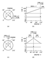
図3(a)は本実施例におけるロータリー式の制御値設定部115の作動領域の一の例を示す。ロータリー式のつまみでは回転角が0°から270°の位置までが作動領域であり、ユーザが所望の回転角につまみを回したときに、その回転角に応じた制御値を制御値設定部115は出力する。
FIG. 3A shows an example of an operating region of the rotary type control
また、図3(b)に示すように、光量を最大とする制御値が出力される回転角が270°の直前に作動トルクピーク位置が設けられている。この作動トルクピーク位置において、物理的に回転方向に対して反発力を発生し、回転に必要なトルクが増加する機構がつまみに組み込まれている。すなわち、つまみを作動領域端である回転角が0°の状態から右に回すと、右に回しきったところに位置するもう一方の作動領域端である回転角が270°の直前で回転方向への反発力が発生する。そしてその反発力に抗してさらにつまみを右に回すと作動トルクピーク位置を超えてもう一方の作動領域端である回転角が270°の状態となる。 Further, as shown in FIG. 3B, the operating torque peak position is provided immediately before the rotation angle at which the control value that maximizes the amount of light is output is 270 °. At this operating torque peak position, a mechanism is incorporated in the knob to physically generate a repulsive force in the direction of rotation and increase the torque required for rotation. That is, when the knob is turned to the right from the state where the rotation angle at the end of the operating region is 0 °, the rotation angle at the other end of the operating region located at the end of the operating region is just before 270 ° in the rotation direction. Repulsive force is generated. Then, when the knob is further turned to the right against the repulsive force, the rotation angle at the other end of the operating region exceeds the operating torque peak position and becomes 270 °.
この図3(a)に示した制御値設定部115が出力する制御値は、説明の便宜上、つまみの回転角が0°のときを0とし、つまみを右に回して反発力が発生する直前を100とする。更に反発力に抗し右に回して作動トルクピーク位置を超えて回転角が270°になったときの制御値を101とする。これら制御値設定部115が出力する制御値は、つまみの位置に応じた値であればこの値には限定しない。
For convenience of explanation, the control value output by the control
また図3(c)に本実施例におけるロータリー式の制御値設定部115の作動領域の他の例を示す。ロータリー式のつまみでは回転角が0°から270°の位置までが作動領域であり、ユーザが所望の回転角につまみを回したときに、その回転角に応じた制御値を制御値設定部115は出力する。
Further, FIG. 3C shows another example of the operating region of the rotary type control
図3(d)に示すように、つまみの作動領域の中間位置である回転角が135°の位置に作動トルクピーク位置が設けられている。この作動トルクピーク位置において、物理的に回転方向に対して反発力を発生して回転に必要なトルクが増加する機構がつまみに組み込まれている。すなわち、つまみを作動領域端である回転角が0°の状態から右に回すと、作動領域の中間位置である回転角が135°の直前で回転方向への反発力が発生する。そしてその反発力に抗してさらにつまみを右に回すと作動トルクピーク位置を超えてもう一方の作動領域端である回転角が270°の位置まで回すことができる。 As shown in FIG. 3D, the operating torque peak position is provided at a position where the rotation angle is 135 °, which is an intermediate position of the operating region of the knob. At this operating torque peak position, a mechanism that physically generates a repulsive force in the rotation direction to increase the torque required for rotation is incorporated in the knob. That is, when the knob is turned to the right from the state where the rotation angle at the end of the operating region is 0 °, a repulsive force in the rotation direction is generated just before the rotation angle at the intermediate position of the operating region is 135 °. Then, when the knob is further turned to the right against the repulsive force, the rotation angle at the other end of the working region can be turned to a position of 270 ° beyond the working torque peak position.
この図3(c)に示した制御値設定部115が出力する制御値は、説明の便宜上、つまみの回転角が0°のときを0とし、つまみを右に回して回転角が135°において反発力が発生する直前を49とする。更に反発力に抗し右に回して作動トルクピーク位置を超えた位置で制御値を50とし、回転角が270°になったときの制御値を100とする。これら制御値設定部115が出力する制御値は、つまみの位置に応じた値であればこの値には限定しない。
For convenience of explanation, the control value output by the control
図3(a)で示したロータリー式の制御値設定部115を用いた場合の図7に示す本実施例の動作処理について説明する。
The operation processing of this embodiment shown in FIG. 7 when the rotary type control
まず、ステップS701では、制御部であるCPU110が画像投影装置100の動作モードと明るさの初期設定を行う。初期設定が必要な理由は、本実施例では後述するステップS702においてCPU110が制御値設定部115から制御値を取得するまでは動作モードと投影画像の明るさの設定が確定しないためである。ここではCPU110は画像投影装置100の動作モードを照明モード、明るさを0%と設定する。照明モードにおける信号処理系の動作については、実施例1で述べたので省略する。また明るさを0%に設定するため、CPU110は光源制御部130に対して、光源160の光量が0%になるように設定する。
First, in step S701, the
またステップS701では、ステップS703における閾値を設定する。図3(a)の制御値設定部115を用いる場合は、作動トルクピーク位置から回転角が大きくなる方向につまみを回したときの回転角である270°のときの制御値である101を閾値として設定する。
Further, in step S701, the threshold value in step S703 is set. When the control
ステップS702では、制御部であるCPU110はユーザによる制御値設定部115上のつまみの操作により出力された制御値を取得する。ステップS702は実施例1におけるステップS502と同様である。
In step S702, the
ステップS703では、CPU110が取得した制御値があらかじめ設定した閾値以上かどうかを判断する。ここで閾値は、上述の通りステップS701においてつまみの回転角が270°のときの制御値である101が設定されている。よって、CPU110が制御値設定部115から取得した制御値が閾値未満、すなわち100以下のときはステップS704へ制御を移し、取得した制御値が101のときはステップS705に制御を移す。
In step S703, it is determined whether or not the control value acquired by the
ステップS704では、CPU110は画像投影装置100の動作モードを照明モードとする。照明モードの実現方法については、実施例1で述べたためここでは省略する。
In step S704, the
ステップS705では、CPU110は画像投影装置100の動作モードを投影モードに設定する。すなわち、CPU110は画像入力部120から入力された映像信号か、あるいはROM112に記憶されていた画像を、画像処理部140で画像処理を行う。その後、CPU110は、光変調素子駆動部150で光変調素子170R,170G,170Bを駆動して投影画像として投影するように設定する。詳しい動作については実施例1で述べたので省略する。
In step S705, the
ステップS706では、CPU110は取得した制御値に応じた光量となるように光源160を制御する光量制御処理を行う。ステップS706は実施例1におけるステップS503と同様である。
In step S706, the
制御値と光量の関係は、制御値が0のとき(つまみの回転角が0°のとき)は光量は0%、制御値が100以上のとき(つまみの位置が作動トルクピーク位置の直前から回転角が270°まで間)は光量は100%に制御される。また、つまみの回転角が0度から作動トルクピーク位置までの角度である場合は、その回転角に正比例して0から100までの値となる制御値に従って光量が制御される。 The relationship between the control value and the amount of light is as follows: when the control value is 0 (when the rotation angle of the knob is 0 °), the amount of light is 0%, and when the control value is 100 or more (the position of the knob is immediately before the operating torque peak position). The amount of light is controlled to 100% while the rotation angle is up to 270 °. When the rotation angle of the knob is an angle from 0 degree to the operating torque peak position, the amount of light is controlled according to a control value that is a value from 0 to 100 in direct proportion to the rotation angle.
ステップS707では、制御を終了するかどうか判定する。例えばユーザによる操作部113の操作や、不図示のリモコンでの操作などによる制御の終了が指示されたかどうかを判定する。制御の終了が判定されなかった場合には、制御をステップS702に戻す。制御の終了が判定された場合には、本処理を終了する。
In step S707, it is determined whether or not to end the control. For example, it is determined whether or not the user has instructed to end the control by operating the
図3(b)に、図3(a)の制御値設定部115を用いたときの作動領域の動作を示す。図7のフローチャートで説明したように、制御値設定部115のつまみの回転角が0°の位置から、回転角が270°の直前にある作動トルクピーク位置までは照明モードとして動作し、光量は制御値に応じて0%から100%まで制御される。つまみの回転角が作動トルクピーク位置を越えて270°になったときには投影モードとなり、このときの光量は100%となる。
FIG. 3B shows the operation of the operating region when the control
次に、図3(c)で示したロータリー式の制御値設定部115を用いた場合の図7に示す本実施例の動作処理について説明する。
Next, the operation processing of the present embodiment shown in FIG. 7 when the rotary type control
まず、ステップS701では、制御部であるCPU110が動作モードと明るさの初期設定を行うが、これは既に述べた通りである。しかし、ステップS701で設定される、ステップS703における閾値には、図3(c)の制御値設定部115を用いる場合、作動トルクピークの位置である回転角135°を越えた位置の制御値である50が設定される。
First, in step S701, the
ステップS702では、制御部であるCPU110はユーザによる制御値設定部115上のつまみの操作により出力された制御値を取得する。
In step S702, the
ステップS703では、CPU110が取得した制御値があらかじめ設定した閾値以上かどうかを判断する。ここで閾値は、上述の通りステップS701において作動トルクピーク位置を超えた位置の制御値である50が設定されている。よって、CPU110が制御値設定部115から取得した制御値が49以下のときはステップS704へ制御を移し、取得した制御値が50以上のときにはステップS705に制御を移す。
In step S703, it is determined whether or not the control value acquired by the
ステップS704では、CPU110は画像投影装置100の動作モードを照明モードとする。照明モードの実現方法については、実施例1で述べたためここでは省略する。
In step S704, the
ステップS705では、CPU110は画像投影装置100の動作モードを投影モードに設定する。すなわち、CPU110は画像入力部120から入力された映像信号か、あるいはROM112に記憶されていた画像を、画像処理部140で画像処理を行う。その後、CPU110は、光変調素子駆動部150で光変調素子170R,170G,170Bを駆動して投影画像として投影するように設定する。詳しい動作については実施例1で述べたので省略する。
In step S705, the
ステップS706では、CPU110は取得した制御値に応じた光量となるように光源160を制御する光量制御処理を行う。ステップS706は実施例1におけるステップS503と同様である。
In step S706, the
制御値と光量の関係は、制御値が0のとき(つまみの回転角が0°のとき)は光量は0%、制御値が49のとき(つまみの回転角が作動トルクピーク位置の直前のとき)には光量は100%に制御される。また、つまみの回転角が0度から作動トルクピーク位置までの角度である場合は、その回転角に正比例して0から49までの値となる制御値に従って光量が上がるよう制御される。そしてつまみの回転角が作動トルクピーク位置を越えた直後の位置では制御値は50となり、そのときの光量は100%とする。制御値が100のとき(つまみの回転角が270°のとき)には光量は0%とする。つまみの回転角が作動トルクピーク位置から270°までの角度である場合は、その回転角に正比例して50から100までの値となる制御値に従って光量が下がるよう制御される。 Regarding the relationship between the control value and the amount of light, when the control value is 0 (when the rotation angle of the knob is 0 °), the amount of light is 0%, and when the control value is 49 (the rotation angle of the knob is immediately before the operating torque peak position). When), the amount of light is controlled to 100%. When the rotation angle of the knob is an angle from 0 degree to the operating torque peak position, the amount of light is controlled to increase according to a control value that is a value from 0 to 49 in direct proportion to the rotation angle. The control value is 50 at the position immediately after the rotation angle of the knob exceeds the operating torque peak position, and the amount of light at that time is 100%. When the control value is 100 (when the rotation angle of the knob is 270 °), the amount of light is set to 0%. When the rotation angle of the knob is an angle from the operating torque peak position to 270 °, the amount of light is controlled to decrease according to a control value which is a value from 50 to 100 in direct proportion to the rotation angle.
ステップS707では、制御を終了するかどうか判定する。例えばユーザによる操作部113の操作や、不図示のリモコンでの操作などによる制御の終了が指示されたかどうかを判定する。制御の終了が判定されなかった場合には、制御をステップS702に戻す。制御の終了が判定された場合には、本処理を終了する。
In step S707, it is determined whether or not to end the control. For example, it is determined whether or not the user has instructed to end the control by operating the
図3(d)に、図3(c)の制御値設定部115を用いたときの作動領域の動作を示す。図7のフローチャートで説明したように、制御値設定部115のつまみの回転角が0°の位置から、回転角が135°の直前にある作動トルクピーク位置までは照明モードとして動作し、光量は制御値に応じて0%から100%まで制御される。つまみの回転角が作動トルクピーク位置である回転角135°を越えると投影モードとなり光量は100%となり、そこから回転角に応じて制御値が大きくなるにつれて光量は下がり、作動領域端である回転角270°では光量は0%となる。
FIG. 3D shows the operation of the operating region when the control
本実施例では、制御値設定部115として図3(a)と図3(c)の形状の例をあげ、動作についてはそれぞれ図3(b)と図3(d)の例をあげて説明した。しかし実現方法はこれに限るものではなく、例えば、制御値設定部115においてはつまみの移動方向での作動トルクピーク位置は無くても良い。また図3(b)や図3(d)ではつまみの位置に合わせて照度を0%から100%まで直線的に制御しているが、総合的な光量の出力特性に合わせて非直線性を持たせても良い。
In this embodiment, examples of the shapes of FIGS. 3 (a) and 3 (c) are given as the control
本実施例では、制御値設定部115は図3に示すロータリー式のつまみを有する場合について説明したが、スライド式のつまみを制御値設定部115が有していても良い。
In this embodiment, the case where the control
本実施例では、画像投影装置100から投射される光量の制御を光源160の光量を制御することで実現しているが、実施例1と同様にこれに限定するものではない。例えば不図示の絞り機構を投影光学系181の前か後ろに配置して、この絞り機構で画像投影装置100から投射される光量を制御しても良い。または、画像処理部140において照明用画像を出力する際の輝度を下げるようにしても良い。
In the present embodiment, the control of the amount of light projected from the
図1では制御値設定部115は画像投影装置100に組み込まれているが、これに限定されない。例えば、画像投影装置100が天井に設置されている場合は、動作モードや明るさを制御する制御値設定部115は壁面に設置してもよい。この場合、制御値伝送用のワイヤーもしくは無線伝送手段を介して、制御値設定部115と、制御値設定部115から離れた位置に設置された画像投影装置100とを通信接続しても良い。
In FIG. 1, the control
本実施例に係る画像投影装置100の構成と動作処理については実施例1と同一である。よって重複した説明は省略する。
The configuration and operation processing of the
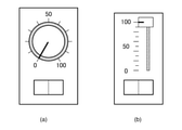
制御値設定部115はユーザ操作に応じて光量と動作モードを制御するための制御値の設定手段である。例えば、制御値設定部115は、従来の白熱灯の調光装置と同様の図4(a)や図4(b)に示すロータリーエンコーダーやリニアエンコーダー等からなるつまみ、及び二値の制御値の出力を制御するロッカースイッチを有する。つまみの操作により連続的な制御値が出力される。すなわち、制御値設定部115の一方の作動領域端では0を出力し、もう一方の作動領域端では100を出力し、その中間領域ではつまみの位置に応じて0から100の間の制御値を出力する。尚、ユーザ操作に応じて上記制御値の設定が可能であれば、制御値設定部115の形状や動作は図4に示すものに限定されるものではない。例えば、タッチパネルからなる操作部113が制御値設定部115を兼ねてもよい。この場合、例えば、操作部113における制御値設定画面の表示時に、タッチパネルの所定位置へのユーザによるフリック操作やスライド操作に応じて制御値が設定される。
The control
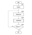
図8のフローチャートを用いて本実施例の動作処理について説明する。 The operation processing of this embodiment will be described with reference to the flowchart of FIG.
まず、ステップS801では、制御部であるCPU110が画像投影装置100の動作モードと明るさの初期設定を行う。初期設定が必要な理由は、本実施例では後述するステップS802においてCPU110が制御値設定部115から制御値を取得するまでは、動作モードと投影画像の明るさの設定が確定しないためである。ここではCPU110は画像投影装置100の動作モードを照明モード、明るさを0%と設定する。照明モードにおける信号処理系の動作については、実施例1で述べたので省略する。また明るさを0%に設定するため、CPU110は光源制御部130に対して、光源160の光量が0%になるように制御する。
First, in step S801, the
ステップS802では、制御部であるCPU110はユーザによる制御値設定部115上のつまみとロッカースイッチの操作により出力された連続的な制御値と二値の制御値を取得する。
In step S802, the
ステップS803では、CPU110が取得した二値の制御値が1であるかどうか判定する。二値の制御値が1でなかったときには制御をステップS804に移し、1であったときには制御をステップS805に移す。尚、取得した二値の制御値に応じて動作モードが決定されればよく、二値の制御値によってどちらの動作モードを選択するかを限定するものではない。
In step S803, it is determined whether or not the binary control value acquired by the
ステップS804では、CPU110は画像投影装置100の動作モードを照明モードに設定する。照明モードの実現方法については、実施例1で述べたためここでは省略する。
In step S804, the
ステップS805では、CPU110は画像投影装置100の動作モードを投影モードに設定する。すなわち、CPU110は画像入力部120から入力された映像信号か、あるいはROM112に記憶されていた画像を、画像処理部140で画像処理を行う。その後、CPU110は、光変調素子駆動部150で光変調素子170R,170G,170Bを駆動して投影画像として投影するように設定する。詳しい動作については実施例1で述べたので省略する。
In step S805, the
ステップS806では、CPU110は取得した連続的な制御値に応じた光量となるように光源160を制御する光量制御処理を行う。CPU110が取得した連続的な制御値が0のときには光量は0%に、取得した連続的な制御値が100のときには光量が100%にと、取得した連続的な制御値に応じた光量となるように、CPU110は光源制御部130を制御する。ステップS806については実施例1におけるステップS503と同様である。
In step S806, the
ステップS807では、制御を終了するかどうか判定する。例えばユーザによる操作部113の操作や、不図示のリモコンでの操作などによる制御の終了が指示されたかどうかを判定する。制御の終了が判定されなかった場合には、制御をステップS802に戻す。制御の終了が判定された場合には、本処理を終了する。
In step S807, it is determined whether or not to end the control. For example, it is determined whether or not the user has instructed to end the control by operating the
本実施例では画像投影装置100から投射される光量の制御を光源160光量を制御することで実現しているが、実施例1と同様にこれに限定するものではない。例えば不図示の絞り機構を投影光学系181の前か後ろに配置して、この絞り機構で画像投影装置100から投射される光量を制御しても良い。または、画像処理部140において照明用画像を出力する際の輝度を下げるようにしても良い。
In the present embodiment, the control of the amount of light projected from the
図1では制御値設定部115は画像投影装置100に組み込まれているが、これに限定されない。例えば、画像投影装置100が天井に設置されている場合は、動作モードや明るさを制御する制御値設定部115は壁面に設置してもよい。この場合、制御値伝送用のワイヤーもしくは無線伝送手段を介して、制御値設定部115と、制御値設定部115から離れた位置に設置された画像投影装置100とを通信接続しても良い。
In FIG. 1, the control
(その他の実施形態)
以上、実施形態例を詳述したが、本発明は、例えば、システム、装置、方法、プログラム若しくは記憶媒体(記録媒体)等としての実施態様をとることが可能である。具体的には、複数の機器から構成されるシステムに適用しても良いし、また、一つの機器からなる装置に適用しても良い。
(Other embodiments)
Although examples of embodiments have been described in detail above, the present invention can be implemented as, for example, a system, an apparatus, a method, a program, a storage medium (recording medium), or the like. Specifically, it may be applied to a system composed of a plurality of devices, or may be applied to a device composed of one device.
なお、本発明は、前述した実施形態の機能を実現するソフトウェアのプログラム(実施形態では図に示すフローチャートに対応したプログラム)を、システムあるいは装置に直接あるいは遠隔から供給する。そして、そのシステムあるいは装置のコンピュータが該供給されたプログラムコードを読み出して実行することによっても達成される場合を含む。 The present invention supplies a software program (in the embodiment, a program corresponding to the flowchart shown in the figure) that realizes the functions of the above-described embodiment directly or remotely to the system or device. It also includes cases where the computer of the system or device is also achieved by reading and executing the supplied program code.
従って、本発明の機能処理をコンピュータで実現するために、該コンピュータにインストールされるプログラムコード自体も本発明を実現するものである。つまり、本発明は、本発明の機能処理を実現するためのコンピュータプログラム自体も含まれる。 Therefore, in order to realize the functional processing of the present invention on a computer, the program code itself installed in the computer also realizes the present invention. That is, the present invention also includes the computer program itself for realizing the functional processing of the present invention.
その場合、プログラムの機能を有していれば、オブジェクトコード、インタプリタにより実行されるプログラム、OSに供給するスクリプトデータ等の形態であっても良い。 In that case, as long as it has a program function, it may be in the form of an object code, a program executed by an interpreter, script data supplied to the OS, or the like.
プログラムを供給するための記録媒体としては、例えば、以下のようなものがある。フロッピー(登録商標)ディスク、ハードディスク、光ディスク、光磁気ディスク、MO、CD-ROM、CD-R、CD-RW、磁気テープ、不揮発性のメモリカード、ROM、DVD(DVD-ROM,DVD-R)。 Examples of the recording medium for supplying the program include the following. Flop (registered trademark) disk, hard disk, optical disk, optical magnetic disk, MO, CD-ROM, CD-R, CD-RW, magnetic tape, non-volatile memory card, ROM, DVD (DVD-ROM, DVD-R) ..
その他、プログラムの供給方法としては、クライアントコンピュータのブラウザを用いてインターネットのホームページからハードディスク等の記録媒体にダウンロードすることによっても供給できる。すなわち、ホームページに接続し、該ホームページから本発明のコンピュータプログラムそのもの、もしくは圧縮され自動インストール機能を含むファイルをダウンロードする。また、本発明のプログラムを構成するプログラムコードを複数のファイルに分割し、それぞれのファイルを異なるホームページからダウンロードすることによっても実現可能である。つまり、本発明の機能処理をコンピュータで実現するためのプログラムファイルを複数のユーザに対してダウンロードさせるWWWサーバも、本発明に含まれるものである。 In addition, as a method of supplying the program, it can also be supplied by downloading it from a homepage of the Internet to a recording medium such as a hard disk using a browser of a client computer. That is, it connects to a homepage and downloads the computer program itself of the present invention or a compressed file including an automatic installation function from the homepage. It can also be realized by dividing the program code constituting the program of the present invention into a plurality of files and downloading each file from different homepages. That is, the present invention also includes a WWW server that causes a plurality of users to download a program file for realizing the functional processing of the present invention on a computer.
また、本発明のプログラムを暗号化してCD-ROM等の記憶媒体に格納してユーザに配布する。そして、所定の条件をクリアしたユーザに対し、インターネットを介してホームページから暗号化を解く鍵情報をダウンロードさせる。そして、その鍵情報を使用することにより暗号化されたプログラムを実行してコンピュータにインストールさせて実現することも可能である。 Further, the program of the present invention is encrypted, stored in a storage medium such as a CD-ROM, and distributed to users. Then, the user who clears the predetermined condition is made to download the key information for decrypting the encryption from the homepage via the Internet. Then, by using the key information, it is also possible to execute an encrypted program and install it on a computer.
また、コンピュータが、読み出したプログラムを実行することによって、前述した実施形態の機能が実現される。その他にも、そのプログラムの指示に基づき、コンピュータ上で稼動しているOSなどが、実際の処理の一部または全部を行い、その処理によっても前述した実施形態の機能が実現され得る。 Further, the function of the above-described embodiment is realized by the computer executing the read program. In addition, the OS running on the computer performs a part or all of the actual processing based on the instruction of the program, and the function of the above-described embodiment can be realized by the processing.
さらに、記録媒体から読み出されたプログラムが、コンピュータに挿入された機能拡張ボードやコンピュータに接続された機能拡張ユニットに備わるメモリに書き込まれた後にも前述した実施形態の機能が実現される。すなわち、そのプログラムの指示に基づき、その機能拡張ボードや機能拡張ユニットに備わるCPUなどが実際の処理の一部または全部を行うことによっても前述した実施形態の機能が実現される。 Further, even after the program read from the recording medium is written in the memory provided in the function expansion board inserted in the computer or the function expansion unit connected to the computer, the functions of the above-described embodiment are realized. That is, the function of the above-described embodiment is realized by performing a part or all of the actual processing by the function expansion board, the CPU provided in the function expansion unit, or the like based on the instruction of the program.
100 画像投影装置
110 CPU
111 RAM
112 ROM
113 操作部
115 制御値設定部
120 画像入力部
130 光源制御部
140 画像処理部
160 光源
100
111 RAM
112 ROM
113
Claims (6)
光を投射する出力手段と、
前記操作部材の位置又は回転角に応じて前記出力手段を制御する制御手段と、を有し、
前記制御手段は、前記操作部材の前記位置又は前記回転角が第1の範囲にある場合に、前記出力手段を、一様な光を出力する照明モードとし、その光量が前記制御値が大きいほど大きくなるように制御し、前記操作部材の前記位置又は前記回転角が第2の範囲にある場合に、前記出力手段を、画像を投影する投影モードとし、その光量が前記制御値が大きいほど小さくなるように制御することを特徴とする画像投影装置。 An operating member that outputs control values according to the position or angle of rotation ,
An output means that projects light,
It has a control means for controlling the output means according to the position or the angle of rotation of the operation member.
The control means sets the output means into an illumination mode that outputs uniform light when the position or the rotation angle of the operation member is in the first range, and the larger the control value is, the more the light amount is. When the position or the angle of rotation of the operating member is in the second range, the output means is set to a projection mode for projecting an image, and the amount of light is smaller as the control value is larger. An image projection device characterized by controlling the angle of rotation.
前記操作部材の前記位置又は前記回転角を前記第1の範囲から前記第2の範囲に変更する場合に前記ユーザにかかる反発力は、前記第1の範囲内で前記位置又は前記回転角を変更する場合に前記ユーザにかかる反発力よりも大きいことを特徴とする請求項1に記載の画像投影装置。 The operation member can change the position or the rotation angle by user operation.
The repulsive force applied to the user when the position or the rotation angle of the operating member is changed from the first range to the second range changes the position or the rotation angle within the first range. The image projection device according to claim 1, wherein the repulsive force applied to the user is larger than the repulsive force applied to the user.
前記操作部材の位置又は回転角に応じて前記出力部を制御する制御ステップを有し、
前記制御ステップにおいて、前記操作部材の前記位置又は前記回転角が第1の範囲にある場合に、前記出力部は、一様な光を出力する照明モードとされ、その光量は前記制御値が大きいほど大きくなるように制御され、前記操作部材の前記位置又は前記回転角が第2の範囲にある場合に、前記出力部は、画像を投影する投影モードとされ、その光量は前記制御値が大きいほど小さくなるように制御されることを特徴とする制御方法。 It is a control method of an image projection device including an operation member that outputs a control value according to a position or an angle of rotation and an output unit that projects light.
It has a control step that controls the output unit according to the position or rotation angle of the operating member.
In the control step, when the position or the rotation angle of the operating member is in the first range, the output unit is set to an illumination mode for outputting uniform light , and the amount of light thereof has a large control value. When the position or the angle of rotation of the operating member is in the second range, the output unit is set to the projection mode for projecting an image, and the amount of light thereof is controlled to have a large control value . A control method characterized in that it is controlled so as to become smaller .
Priority Applications (1)
| Application Number | Priority Date | Filing Date | Title |
|---|---|---|---|
| JP2017199558A JP7039242B2 (en) | 2017-10-13 | 2017-10-13 | Image projection device, its control method, and program |
Applications Claiming Priority (1)
| Application Number | Priority Date | Filing Date | Title |
|---|---|---|---|
| JP2017199558A JP7039242B2 (en) | 2017-10-13 | 2017-10-13 | Image projection device, its control method, and program |
Publications (3)
| Publication Number | Publication Date |
|---|---|
| JP2019074597A JP2019074597A (en) | 2019-05-16 |
| JP2019074597A5 JP2019074597A5 (en) | 2020-11-12 |
| JP7039242B2 true JP7039242B2 (en) | 2022-03-22 |
Family
ID=66544123
Family Applications (1)
| Application Number | Title | Priority Date | Filing Date |
|---|---|---|---|
| JP2017199558A Active JP7039242B2 (en) | 2017-10-13 | 2017-10-13 | Image projection device, its control method, and program |
Country Status (1)
| Country | Link |
|---|---|
| JP (1) | JP7039242B2 (en) |
Families Citing this family (1)
| Publication number | Priority date | Publication date | Assignee | Title |
|---|---|---|---|---|
| JP7320753B2 (en) * | 2019-10-31 | 2023-08-04 | パナソニックIpマネジメント株式会社 | control system |
Citations (5)
| Publication number | Priority date | Publication date | Assignee | Title |
|---|---|---|---|---|
| JP2003280091A (en) | 2002-03-26 | 2003-10-02 | Olympus Optical Co Ltd | Projection display device |
| JP2004341206A (en) | 2003-05-15 | 2004-12-02 | Olympus Corp | Display apparatus |
| JP2005130250A (en) | 2003-10-24 | 2005-05-19 | Vodafone Kk | Information communication terminal |
| JP2006091092A (en) | 2004-09-21 | 2006-04-06 | Nikon Corp | Projector |
| US20110248983A1 (en) | 2010-04-09 | 2011-10-13 | Samsung Electronics Co. Ltd. | Method and apparatus for operating projection mode in projection device |
-
2017
- 2017-10-13 JP JP2017199558A patent/JP7039242B2/en active Active
Patent Citations (5)
| Publication number | Priority date | Publication date | Assignee | Title |
|---|---|---|---|---|
| JP2003280091A (en) | 2002-03-26 | 2003-10-02 | Olympus Optical Co Ltd | Projection display device |
| JP2004341206A (en) | 2003-05-15 | 2004-12-02 | Olympus Corp | Display apparatus |
| JP2005130250A (en) | 2003-10-24 | 2005-05-19 | Vodafone Kk | Information communication terminal |
| JP2006091092A (en) | 2004-09-21 | 2006-04-06 | Nikon Corp | Projector |
| US20110248983A1 (en) | 2010-04-09 | 2011-10-13 | Samsung Electronics Co. Ltd. | Method and apparatus for operating projection mode in projection device |
Also Published As
| Publication number | Publication date |
|---|---|
| JP2019074597A (en) | 2019-05-16 |
Similar Documents
| Publication | Publication Date | Title |
|---|---|---|
| JP5494415B2 (en) | Projection type display device and control method thereof | |
| JP6299099B2 (en) | Projector and projector control method | |
| US9307210B2 (en) | Image output apparatus, method, and medium | |
| JP7039242B2 (en) | Image projection device, its control method, and program | |
| US20230070178A1 (en) | Control device, and control method | |
| JP6598534B2 (en) | Projection apparatus and projection method | |
| JP7166775B2 (en) | Display device control device, control method, display system and program | |
| JP4374994B2 (en) | Projector and projector system | |
| JP2019134206A (en) | Projection device and control method therefor | |
| JP6545034B2 (en) | Display device, display method and display system | |
| JP7163933B2 (en) | Control device, control method and control program | |
| JP2018054912A (en) | Projection-type display device and method for controlling the same | |
| JP2020061688A (en) | Projection device, control method of the same, program, and storage medium | |
| JP7508937B2 (en) | Display device and control method for display device | |
| JP2024082769A (en) | Image display system, image supply device, and display device | |
| JP5386787B2 (en) | Projection apparatus, projection control method, and program | |
| JP2006171155A (en) | Image projection apparatus | |
| JP2017198779A (en) | Projection type display device and control method thereof | |
| JP2021110836A (en) | Display device and program | |
| JP2021087203A (en) | Display device and program | |
| JP2022038697A (en) | Method for controlling display, and display | |
| JP2021136492A (en) | Operating method for electronic apparatus, and electronic apparatus | |
| JP2014130182A (en) | Display device | |
| JP2020030267A (en) | Projection device | |
| JP2020008729A (en) | Projection device, control device, projection device control method and program |
Legal Events
| Date | Code | Title | Description |
|---|---|---|---|
| A521 | Request for written amendment filed |
Free format text: JAPANESE INTERMEDIATE CODE: A523 Effective date: 20200930 |
|
| A621 | Written request for application examination |
Free format text: JAPANESE INTERMEDIATE CODE: A621 Effective date: 20200930 |
|
| A977 | Report on retrieval |
Free format text: JAPANESE INTERMEDIATE CODE: A971007 Effective date: 20210630 |
|
| A131 | Notification of reasons for refusal |
Free format text: JAPANESE INTERMEDIATE CODE: A131 Effective date: 20210803 |
|
| A521 | Request for written amendment filed |
Free format text: JAPANESE INTERMEDIATE CODE: A523 Effective date: 20210922 |
|
| TRDD | Decision of grant or rejection written | ||
| A01 | Written decision to grant a patent or to grant a registration (utility model) |
Free format text: JAPANESE INTERMEDIATE CODE: A01 Effective date: 20220208 |
|
| A61 | First payment of annual fees (during grant procedure) |
Free format text: JAPANESE INTERMEDIATE CODE: A61 Effective date: 20220309 |
|
| R151 | Written notification of patent or utility model registration |
Ref document number: 7039242 Country of ref document: JP Free format text: JAPANESE INTERMEDIATE CODE: R151 |