WO2022196422A1 - カテーテル組立体 - Google Patents
カテーテル組立体 Download PDFInfo
- Publication number
- WO2022196422A1 WO2022196422A1 PCT/JP2022/009862 JP2022009862W WO2022196422A1 WO 2022196422 A1 WO2022196422 A1 WO 2022196422A1 JP 2022009862 W JP2022009862 W JP 2022009862W WO 2022196422 A1 WO2022196422 A1 WO 2022196422A1
- Authority
- WO
- WIPO (PCT)
- Prior art keywords
- catheter
- needle
- hub
- reinforcing
- catheter assembly
- Prior art date
- Legal status (The legal status is an assumption and is not a legal conclusion. Google has not performed a legal analysis and makes no representation as to the accuracy of the status listed.)
- Ceased
Links
Images





Classifications
-
- A—HUMAN NECESSITIES
- A61—MEDICAL OR VETERINARY SCIENCE; HYGIENE
- A61M—DEVICES FOR INTRODUCING MEDIA INTO, OR ONTO, THE BODY; DEVICES FOR TRANSDUCING BODY MEDIA OR FOR TAKING MEDIA FROM THE BODY; DEVICES FOR PRODUCING OR ENDING SLEEP OR STUPOR
- A61M25/00—Catheters; Hollow probes
- A61M25/01—Introducing, guiding, advancing, emplacing or holding catheters
- A61M25/06—Body-piercing guide needles or the like
- A61M25/0606—"Over-the-needle" catheter assemblies, e.g. I.V. catheters
-
- A—HUMAN NECESSITIES
- A61—MEDICAL OR VETERINARY SCIENCE; HYGIENE
- A61M—DEVICES FOR INTRODUCING MEDIA INTO, OR ONTO, THE BODY; DEVICES FOR TRANSDUCING BODY MEDIA OR FOR TAKING MEDIA FROM THE BODY; DEVICES FOR PRODUCING OR ENDING SLEEP OR STUPOR
- A61M25/00—Catheters; Hollow probes
- A61M25/01—Introducing, guiding, advancing, emplacing or holding catheters
- A61M25/06—Body-piercing guide needles or the like
- A61M25/0612—Devices for protecting the needle; Devices to help insertion of the needle, e.g. wings or holders
- A61M25/0618—Devices for protecting the needle; Devices to help insertion of the needle, e.g. wings or holders having means for protecting only the distal tip of the needle, e.g. a needle guard
- A61M25/0625—Devices for protecting the needle; Devices to help insertion of the needle, e.g. wings or holders having means for protecting only the distal tip of the needle, e.g. a needle guard with a permanent connection to the needle hub, e.g. a guiding rail, a locking mechanism or a guard advancement mechanism
-
- A—HUMAN NECESSITIES
- A61—MEDICAL OR VETERINARY SCIENCE; HYGIENE
- A61M—DEVICES FOR INTRODUCING MEDIA INTO, OR ONTO, THE BODY; DEVICES FOR TRANSDUCING BODY MEDIA OR FOR TAKING MEDIA FROM THE BODY; DEVICES FOR PRODUCING OR ENDING SLEEP OR STUPOR
- A61M25/00—Catheters; Hollow probes
- A61M25/0021—Catheters; Hollow probes characterised by the form of the tubing
- A61M25/0023—Catheters; Hollow probes characterised by the form of the tubing by the form of the lumen, e.g. cross-section, variable diameter
- A61M25/0026—Multi-lumen catheters with stationary elements
- A61M25/0032—Multi-lumen catheters with stationary elements characterized by at least one unconventionally shaped lumen, e.g. polygons, ellipsoids, wedges or shapes comprising concave and convex parts
-
- A—HUMAN NECESSITIES
- A61—MEDICAL OR VETERINARY SCIENCE; HYGIENE
- A61M—DEVICES FOR INTRODUCING MEDIA INTO, OR ONTO, THE BODY; DEVICES FOR TRANSDUCING BODY MEDIA OR FOR TAKING MEDIA FROM THE BODY; DEVICES FOR PRODUCING OR ENDING SLEEP OR STUPOR
- A61M25/00—Catheters; Hollow probes
- A61M25/01—Introducing, guiding, advancing, emplacing or holding catheters
- A61M25/0102—Insertion or introduction using an inner stiffening member, e.g. stylet or push-rod
-
- A—HUMAN NECESSITIES
- A61—MEDICAL OR VETERINARY SCIENCE; HYGIENE
- A61M—DEVICES FOR INTRODUCING MEDIA INTO, OR ONTO, THE BODY; DEVICES FOR TRANSDUCING BODY MEDIA OR FOR TAKING MEDIA FROM THE BODY; DEVICES FOR PRODUCING OR ENDING SLEEP OR STUPOR
- A61M25/00—Catheters; Hollow probes
- A61M25/01—Introducing, guiding, advancing, emplacing or holding catheters
- A61M25/06—Body-piercing guide needles or the like
- A61M25/0612—Devices for protecting the needle; Devices to help insertion of the needle, e.g. wings or holders
- A61M25/0631—Devices for protecting the needle; Devices to help insertion of the needle, e.g. wings or holders having means for fully covering the needle after its withdrawal, e.g. needle being withdrawn inside the handle or a cover being advanced over the needle
-
- A—HUMAN NECESSITIES
- A61—MEDICAL OR VETERINARY SCIENCE; HYGIENE
- A61M—DEVICES FOR INTRODUCING MEDIA INTO, OR ONTO, THE BODY; DEVICES FOR TRANSDUCING BODY MEDIA OR FOR TAKING MEDIA FROM THE BODY; DEVICES FOR PRODUCING OR ENDING SLEEP OR STUPOR
- A61M25/00—Catheters; Hollow probes
- A61M25/01—Introducing, guiding, advancing, emplacing or holding catheters
- A61M25/06—Body-piercing guide needles or the like
- A61M25/0612—Devices for protecting the needle; Devices to help insertion of the needle, e.g. wings or holders
- A61M25/0643—Devices having a blunt needle tip, e.g. due to an additional inner component
-
- A—HUMAN NECESSITIES
- A61—MEDICAL OR VETERINARY SCIENCE; HYGIENE
- A61M—DEVICES FOR INTRODUCING MEDIA INTO, OR ONTO, THE BODY; DEVICES FOR TRANSDUCING BODY MEDIA OR FOR TAKING MEDIA FROM THE BODY; DEVICES FOR PRODUCING OR ENDING SLEEP OR STUPOR
- A61M25/00—Catheters; Hollow probes
- A61M25/01—Introducing, guiding, advancing, emplacing or holding catheters
- A61M2025/0175—Introducing, guiding, advancing, emplacing or holding catheters having telescopic features, interengaging nestable members movable in relations to one another
-
- A—HUMAN NECESSITIES
- A61—MEDICAL OR VETERINARY SCIENCE; HYGIENE
- A61M—DEVICES FOR INTRODUCING MEDIA INTO, OR ONTO, THE BODY; DEVICES FOR TRANSDUCING BODY MEDIA OR FOR TAKING MEDIA FROM THE BODY; DEVICES FOR PRODUCING OR ENDING SLEEP OR STUPOR
- A61M25/00—Catheters; Hollow probes
- A61M25/0043—Catheters; Hollow probes characterised by structural features
- A61M25/005—Catheters; Hollow probes characterised by structural features with embedded materials for reinforcement, e.g. wires, coils, braids
- A61M25/0053—Catheters; Hollow probes characterised by structural features with embedded materials for reinforcement, e.g. wires, coils, braids having a variable stiffness along the longitudinal axis, e.g. by varying the pitch of the coil or braid
-
- A—HUMAN NECESSITIES
- A61—MEDICAL OR VETERINARY SCIENCE; HYGIENE
- A61M—DEVICES FOR INTRODUCING MEDIA INTO, OR ONTO, THE BODY; DEVICES FOR TRANSDUCING BODY MEDIA OR FOR TAKING MEDIA FROM THE BODY; DEVICES FOR PRODUCING OR ENDING SLEEP OR STUPOR
- A61M25/00—Catheters; Hollow probes
- A61M25/01—Introducing, guiding, advancing, emplacing or holding catheters
- A61M25/06—Body-piercing guide needles or the like
- A61M25/0693—Flashback chambers
Definitions
- the present invention relates to a catheter assembly.
- a catheter assembly has been used for continuous infusion into a patient's blood vessel.
- the catheter assembly has a relatively flexible catheter (outer needle) and an inner needle that is inserted into the lumen of the catheter and has a sharp tip at the tip (for example, JP-A-2008-173463). ).
- the procedure for indwelling such a catheter assembly in a patient's blood vessel is as follows. First, a user such as a doctor or nurse attaches the catheter assembly to the patient's skin with the tip of the inner needle protruding from the tip of the catheter. puncture the When the blade surface of the needle tip of the inner needle enters the blood vessel, blood flows back (also called flash bag) through the inner needle, and the user visually confirms that the blood vessel has been secured. After that, the inner needle is pulled out and the catheter is advanced into the blood vessel, thereby indwelling the catheter in the blood vessel.
- a user such as a doctor or nurse attaches the catheter assembly to the patient's skin with the tip of the inner needle protruding from the tip of the catheter. puncture the When the blade surface of the needle tip of the inner needle enters the blood vessel, blood flows back (also called flash bag) through the inner needle, and the user visually confirms that the blood vessel has been secured. After that, the inner needle is pulled out and the catheter is advanced into the
- the catheter since the catheter is flexible, it is difficult to damage the posterior wall of the blood vessel, but the operation force is difficult to transmit with the catheter alone, making it difficult to push it into the blood vessel. Therefore, some users may advance the catheter while leaving the highly rigid inner needle inside the catheter in order to facilitate advancement of the catheter.
- one embodiment aims to provide a catheter assembly that allows the catheter to be easily advanced without damaging the posterior wall of the blood vessel.
- One aspect of the following disclosure is a catheter having a first lumen, a catheter hub joined to a proximal end of the catheter, and a catheter extending through the first lumen of the catheter and having a second lumen.
- a reinforcing needle having a blunt tip, a reinforcing needle hub joined to the proximal end of the reinforcing needle, and a sharp needle tip inserted through the second lumen of the reinforcing needle.
- an inner needle an inner needle hub joined to the proximal end of the inner needle, a first fixing portion for fixing the catheter hub and the reinforcing needle hub so as not to be detachable against an operation of axially pulling them out; a second fixing part for fixing the needle hub and the inner needle hub to each other, wherein the reinforcing needle has higher rigidity than the catheter and protrudes from the tip of the catheter, and the inner needle is attached to the reinforcing needle.
- the catheter assembly which protrudes from the tip of the needle.
- the catheter can be easily advanced without damaging the posterior wall of the blood vessel.
- FIG. 1 is a plan view of a catheter assembly according to a first embodiment
- FIG. FIG. 2 is a cross-sectional view of the vicinity of the distal end of the catheter assembly of FIG. 1;
- FIG. 2 is a cross-sectional view near the proximal end of the catheter assembly of FIG. 1;
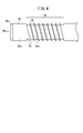
- FIG. 2 is a plan view of the vicinity of the tip of the reinforcing needle of FIG. 1;
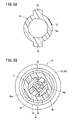
- 5A is a cross-sectional view of the proximal end of the catheter hub of FIG. 1
- FIG. 5B is a cross-sectional view of the reinforced needle hub of FIG. 1 viewed from distal to proximal.
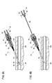
- 6A is an explanatory diagram showing a step of puncturing a blood vessel with the catheter assembly of FIG. 1, and FIG.
- FIG. 6B is an explanatory diagram showing a step of pulling out an inner needle from the catheter assembly that has punctured the blood vessel.
- FIG. 7A is an illustration showing the step of advancing the catheter and stiffening needle inside the blood vessel
- FIG. 7B is an illustration showing deformation of the catheter and stiffening needle.
- 8A is a plan view of the vicinity of the tip of the reinforcing needle according to the second embodiment
- FIG. 8B is a cross-sectional view of the reinforcing needle along line VIIIB-VIIIB in FIG. 8A.
- FIG. 11 is a plan view of a reinforcing needle according to a third embodiment
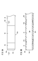
- 10A is a plan view of the reinforcing needle according to the fourth embodiment
- FIG. 10B is a cross-sectional view of the reinforcing needle along line XB-XB of FIG. 10A.
- FIG. 11 is a plan view of a catheter assembly according to a fifth embodiment; 12A is a cross-sectional view of the locking portion in FIG. 11 in a fixed state, FIG. 12B is a cross-sectional view of the locking portion in FIG. 11 in a released state, and FIG. It is a cross-sectional view of the part.
- FIG. 11 is a plan view of a catheter assembly according to a sixth embodiment;
- the catheter assembly 10 As shown in FIG. 1, the catheter assembly 10 according to this embodiment includes a catheter section 12, a reinforcing needle section 14 inserted inside the catheter section 12, and an inner needle inserted inside the reinforcing needle section 14. a portion 16;
- the catheter assembly 10 is used for administering an infusion, etc., with the catheter portion 12 left in a blood vessel 104 (see FIG. 6A).
- the reinforcing needle portion 14 and the inner needle portion 16 are used when puncturing the catheter portion 12 , and are removed from the catheter portion 12 after puncturing the catheter portion 12 .
- the catheter section 12 has a long tubular catheter 18 and a catheter hub 20 joined to the proximal end of the catheter 18 .
- Catheter 18 is a member left in blood vessel 104 . As shown in FIG. 2, the interior of the catheter 18 is formed with a first lumen 18a extending therethrough in the axial direction. The distal end of the catheter 18 is provided with a blunt (non-sharp) distal end 18b.
- Catheter 18 is made of a flexible resin material to prevent damage to blood vessel 104 .
- the catheter hub 20 is formed in a cylindrical shape having an outer diameter larger than that of the catheter 18.
- a connecting portion 22 tapered toward the distal end is formed at the distal end of the catheter hub 20 , and the catheter 18 is liquid-tightly joined to the connecting portion 22 .
- a cavity 20a communicating with the first lumen 18a of the catheter 18 is formed inside the catheter hub 20, a cavity 20a communicating with the first lumen 18a of the catheter 18 is formed.
- a first projection 24 projecting outward in a flange shape is formed on the proximal end side of the catheter hub 20 .
- at least one pair of first protrusions 24 are formed at opposing positions on at least a portion of the catheter hub 20 in the circumferential direction.
- Such a catheter hub 20 is made of a resin material that is harder than the catheter 18 .
- the reinforcing needle portion 14 has a reinforcing needle 26 and a reinforcing needle hub 28 connected to the proximal end of the reinforcing needle 26, as shown in FIG.
- the reinforcing needle 26 is a hollow cylindrical member elongated in the axial direction. As shown in FIG. 2, a second lumen 26a is formed inside the reinforcing needle 26 so as to extend therethrough in the axial direction.
- the reinforcing needle 26 has an outer diameter that allows it to pass through the first lumen 18 a of the catheter 18 and is inserted inside the catheter 18 .
- the reinforcing needle 26 is formed longer than the catheter 18, and its tip portion 26b slightly protrudes from the tip portion 18b of the catheter 18 in the initial state.
- the tip 26b of the reinforcing needle 26 is formed blunt to prevent damage to the blood vessel 104, and the outer periphery of the tip 26b is chamfered 26c to remove sharp edges.
- the reinforcing needle 26 is harder and has higher rigidity than the catheter 18 in order to reinforce the flexible catheter 18.
- materials for the reinforcing needles 26 include metal materials such as stainless steel and hard resin materials.
- the reinforcing needle 26 has a flexible portion 30 formed near the distal end portion 26b so that the vicinity of the distal end portion can be bent.
- the flexible portion 30 is formed as a tubular flexible portion having a predetermined length in the axial direction.
- the flexible portion 30 includes a thin portion 30a formed thinner than other portions of the reinforcing needle 26, and is formed more flexible than the other portions of the reinforcing needle 26. - ⁇
- the flexible portion 30 is provided closer to the proximal end than the distal end portion 18b of the catheter 18 and is hidden inside the catheter 18 .
- the axial length of the flexible portion 30 can be, for example, 3 mm to 10 mm.
- the flexible portion 30 of this embodiment has a concave-convex structure having a plurality of concave portions 32 provided on the outer peripheral portion of the reinforcing needle 26 and convex portions 33 provided adjacent to the concave portions 32. Become. The portion formed thin by the concave portion 32 gives the reinforcing needle 26 flexibility.
- the concave portion 32 of the flexible portion 30 is not limited to a groove having a semicircular cross section as shown in the drawing, and may be a groove having a rectangular shape. Alternatively, the recess 32 may be formed as a notch with a narrower width.
- the pattern of the concave portion 32 is not limited to a spiral shape, and may be formed in a mesh shape, a corrugated shape, or the like.
- a reinforcing needle hub 28 is provided on the proximal end side of the reinforcing needle 26 .
- the reinforcing needle hub 28 includes a catheter hub connecting portion 34 provided on the distal side and an inner needle hub mounting portion 36 provided on the proximal side.
- the catheter hub connecting portion 34 has a structure similar to a male luer lock, and includes a tip 38 that protrudes toward the distal end and is inserted into the catheter hub 20, and a cylindrical lock portion 40 that surrounds the outer circumference of the tip 38. .
- the chip 38 has a shaft hole 38a that penetrates in the axial direction.
- the shaft hole 38a is formed to have an inner diameter capable of accommodating the reinforcing needle 26 therein.
- a proximal end portion of the reinforcing needle 26 is joined to the shaft hole 38a by a method such as adhesion. That is, tip 38 retains reinforcing needle 26 .
- the tip 38 is inserted into the cavity 20a of the catheter hub 20, and the reinforcing needle hub 28 and the catheter hub 20 are connected through the tip 38 in a liquid-tight manner.
- the locking part 40 (first fixing part) is formed in a cylindrical shape with a bottom surrounding the outside of the chip 38 .
- An inner peripheral surface 40 a of the locking portion 40 is provided with a second helical projection 42 protruding inward, which constitutes a screw structure to be screwed onto the first projection 24 of the catheter hub 20 .
- Catheter hub 20 has a first projection 24 at its proximal end.
- the first protrusion 24 of the catheter hub 20 is formed to protrude outward from at least a portion of the outer peripheral portion of the catheter hub 20 in the circumferential direction.
- the first projections 24 are provided, for example, as a pair, at positions facing each other in the circumferential direction.
- the shape of the first protrusion 24 is not limited to the illustrated example, and one protrusion may be formed continuously over a range of half or more in the circumferential direction. Also, three or more first protrusions 24 may be provided separately in the circumferential direction.
- the first protrusion 24 of the catheter hub 20 is screwed into the second protrusion 42 of the locking portion 40, so that the catheter hub 20 and the stiffening needle hub 28 can be pulled apart by a simple pull-out operation. fixed so that it does not come off.
- the inner needle hub mounting portion 36 on the proximal side of the reinforcing needle hub 28 is formed in a cylindrical shape having a circular hollow portion 36a inside, and the hollow portion 36a opens toward the proximal side. .
- the hollow portion 36a communicates with the shaft hole 38a.
- the inner needle section 16 has an inner needle 44 and an inner needle hub 46 connected to the proximal end of the inner needle 44 .
- the inner needle 44 is a hollow needle having a sharp tip 48 at its tip.
- the outer diameter of the inner needle 44 is smaller than the inner diameter of the second lumen 26 a , and the inner needle 44 is inserted into the second lumen 26 a of the reinforcing needle 26 .
- the inner needle 44 is longer than the reinforcing needle 26 , and the tip 48 of the inner needle 44 protrudes from the distal end portion 26 b of the reinforcing needle 26 in the initial state.
- a proximal end of the inner needle 44 is held by an inner needle hub 46 .
- the inner needle hub 46 has a fitting portion 50 (second fixing portion) inserted into the inner needle hub mounting portion 36 on the distal end side, and an inner needle hub body portion 52 extending toward the proximal end side of the fitting portion 50 .
- the fitting portion 50 has a shaft hole 50a and holds the inner needle 44 in the shaft hole 50a.
- the fitting portion 50 has an outer diameter that allows it to be inserted into the hollow portion 36 a of the inner needle hub mounting portion 36 . In the initial state, the fitting portion 50 is inserted into the hollow portion 36a of the inner needle hub mounting portion 36 so that the inner needle hub 46 and the reinforcing needle hub 28 are connected. The inner needle hub 46 and the reinforcing needle hub 28 are fixed by the frictional force between the fitting portion 50 and the inner peripheral portion of the hollow portion 36a.
- the inner needle hub main body portion 52 is a cylindrical member having a grippable outer diameter, and is made of a transparent or translucent resin material in order to facilitate visual confirmation of the backflow of blood caused by the flash bag. .
- the inner needle hub body portion 52 and the fitting portion 50 are integrally formed.
- connection strength against an axial tensile force between the fitting portion 50 and the inner needle hub mounting portion 36 is smaller than the connection strength against an axial tensile force between the reinforcing needle hub 28 and the catheter hub 20 . Therefore, when the inner needle hub 46 is pulled, the inner needle portion 16 is pulled out before the reinforcing needle portion 14 .
- the catheter assembly 10 of this embodiment is configured as described above, and its operation will be described below.
- the user holds catheter hub 20 and stiffening needle hub 28 of catheter assembly 10 with one hand and directs needle tip 48 of inner needle 44 through patient's skin 102 toward blood vessel 104. Puncture.
- the needle tip 48 of the inner needle 44 punctures the blood vessel 104
- the blood inside the blood vessel 104 flows backward through the inner needle 44 and flows into the inner needle hub 46 .
- the user visually recognizes that the needle tip 48 has punctured the blood vessel 104 .
- the user holds the inner needle hub body 52 with the other hand and pulls it out of the catheter assembly 10 in the proximal direction. As a result, only the inner needle portion 16 is withdrawn from the catheter assembly 10 . Since the stiffening needle hub 28 is engaged with the first protrusion 24 of the catheter hub 20 at the second protrusion 42, the stiffening needle portion 14 is not withdrawn from the catheter assembly 10 in this operation.
- the user pushes the catheter 18 into the blood vessel 104, as shown in FIG. 7A.
- the catheter 18 is advanced with the stiffening needle 26 while being stiffened by the stiffening needle 26 inside. Since deformation of the catheter 18 can be prevented by the reinforcement needle 26 , the operating force from the catheter hub 20 and the reinforcement needle hub 28 is reliably transmitted to the distal end of the catheter 18 . Therefore, catheter 18 can be efficiently advanced through blood vessel 104 .
- the user rotates stiffening needle hub 28 relative to catheter hub 20 so that second projection 42 of stiffening needle hub 28 and catheter hub 20 are aligned.
- the locked state by the first protrusion 24 of is released.
- the user then withdraws the stiffening needle hub 28 from the catheter hub 20 to completely remove the stiffening needle portion 14 from the catheter portion 12 .
- the user fixes the catheter hub 20 on the skin 102 to complete the indwelling of the catheter section 12 .
- the catheter assembly 10 of this embodiment has the following effects.
- the catheter assembly 10 of this embodiment includes a catheter 18 having a first lumen 18a, a catheter hub 20 joined to the proximal end of the catheter 18, a first lumen 18a of the catheter 18, and a first lumen 18a.
- a reinforcing needle 26 having two lumens 26a and a blunt distal end 26b; a reinforcing needle hub 28 joined to the proximal end of the reinforcing needle 26;
- the inner needle 44 having a sharp needle point 48 at the distal end, the inner needle hub 46 joined to the proximal end of the inner needle 44, the catheter hub 20 and the reinforcing needle hub 28 are separated from the operation of pulling them out in the axial direction.
- a first fixing portion e.g., locking portion 43
- a second fixing portion e.g., fitting portion 50
- Needle 26 has a higher stiffness than catheter 18 and protrudes from the tip of catheter 18 and inner needle 44 protrudes from the tip of stiffening needle 26 .
- the catheter 18 is reinforced by the reinforcing needle 26, so that when pushing the catheter 18 into the blood vessel 104, it can be smoothly advanced even when the inner needle 44 is completely pulled out.
- the inner needle 44 can be completely pulled out after puncturing the blood vessel 104 , and an event such as the needle tip 48 of the inner needle 44 damaging the back wall of the blood vessel 104 can be prevented.
- the first fixing portion may fix the catheter hub 20 and the reinforcing needle hub 28 more firmly than the fixing between the reinforcing needle hub 28 and the inner needle hub 46 by the second fixing portion.
- This configuration can prevent the reinforcing needle hub 28 from coming off the catheter hub 20 when the inner needle hub 46 is pulled out, and the reinforcing needle 26 can be retained inside the catheter 18 .
- the first fixing portion includes a first protrusion 24 protruding radially outward from the proximal end of the catheter hub 20 and a cylindrically protruding distal end from the reinforcing needle hub 28 to form the catheter hub.
- a locking portion 40 that surrounds at least a portion of the outer side of the catheter hub 20 and has a spiral second projection 42 that screws together with the first projection 24 on an inner peripheral surface 40a that faces the catheter hub 20.
- the first fixing portion may axially fix the catheter hub 20 and the reinforcing needle hub 28 rotatably to each other.
- the locking portion 43 may be unlocked by rotating the catheter hub 20 and the reinforcing needle hub 28 relative to each other.
- the reinforcing needle 26 may have a flexible portion 30 that makes the tip bendable. According to this configuration, when the tips of the catheter 18 and the reinforcing needle 26 abut against the rear wall of the blood vessel 104, the tip of the catheter 18 can be flexibly bent, and damage to the blood vessel 104 can be prevented.
- the flexible section 30 may have a flexible section provided at a position spaced from the distal end to the proximal side. With this configuration, the flexible portion 30 can flexibly bend regardless of the rotational position of the reinforcing needle 26 .
- the flexible portion 30 has a concave-convex structure having a plurality of concave portions 32 forming a thin outer circumference of the reinforcing needle 26 and convex portions 33 provided adjacent to the concave portions 32, good.
- the reinforcing needle 26A of this embodiment differs from the reinforcing needle 26 of FIG. 4 in the flexible portion 30A.
- the same reference numerals are given to the same configuration as the reinforcing needle 26 in FIG. 4, and detailed description thereof will be omitted.
- the flexible portion 30A has an intermediate portion 56 made of a material that is more flexible than the rest of the reinforcing needle 26A.
- the intermediate portion 56 is formed as a cylindrical member made of easily elastically deformable rubber, elastomer, or resin material.
- the intermediate portion 56 has inclined surfaces 56a and 56b whose outer diameters gradually decrease on the distal end side and the proximal end side. It is joined to the body portion 58 .
- the joining area is increased, and the intermediate portion 56 can be joined more firmly to the main body portion 58 .
- the flexible portion 30A is made of a material that is more flexible than the other portions. Also with this configuration, the tip of the reinforcing needle 26A can be flexibly curved, and injury to the blood vessel 104 can be prevented.
- the reinforcing needle 26B of this embodiment includes a coiled wire 60 and a distal tip 62 connected to the distal end of the wire 60 .
- the wire 60 has a body portion 64 tightly wound in the axial direction and an intermediate portion 65 loosely wound.
- the intermediate portion 65 is provided near the tip of the wire 60 .
- the wire 60 is tightly wound in the body portion 64, making it difficult to bend. It is In the reinforcing needle 26B of this embodiment, the intermediate portion 65 constitutes the flexible portion 30B.
- the distal tip 62 is a cylindrical member having a blunt distal end portion 26b, and a chamfered portion 26c is provided on the outer peripheral portion thereof.
- the reinforcing needle 26B of this embodiment described above has a rigid member (for example, a wire 60) that is wound along the outer peripheral portion from the proximal end to the distal end to provide rigidity, and the flexible portion 30B is a rigid member. are formed with a sparse density. Also with this configuration, the tip of the reinforcing needle 26B can be flexibly curved, and injury to the blood vessel 104 can be prevented.
- a rigid member for example, a wire 60
- the flexible portion 30B is a rigid member.
- a reinforcing needle 26C of this embodiment has a structure in which a braid wire 66 is wound around the outer peripheral portion for reinforcement.
- the same reference numerals are given to the same configuration as the reinforcing needle 26 in FIG. 4, and detailed description thereof will be omitted.
- the reinforcing needle 26C has an inner layer 68 formed in a thin tubular shape.
- the inner layer 68 is formed flexible.
- a braided wire 66 made of a metal wire is wound around the outer peripheral portion of the inner layer 68 as a reinforcing structure. Further, the braided wire 66 is molded with an outer layer 70 made of resin.
- a flexible portion 30C that is flexibly bendable is formed in the vicinity of the distal end portion 26b of the reinforcing needle 26C.
- the flexible portion 30C is formed by winding the braid wire 66 more loosely than the other portions.
- the reinforcing needles 26C of this embodiment also provide the same effect as the reinforcing needles 26 of the first embodiment.
- the catheter assembly 10D differs from the catheter assembly 10 of FIG. 1 in the structure of the locking portion 43D that engages the catheter hub 20 and the reinforcing needle hub 28D.
- the same components as in the catheter assembly 10 are denoted by the same reference numerals, and detailed description thereof will be omitted.
- the locking portion 43D (first fixing portion) includes a locking mechanism portion 72 protruding from the outer peripheral portion of the catheter hub 20 and a locking portion extending from the reinforcing needle hub 28D toward the distal end side. a pin 80;
- the lock mechanism section 72 has a rectangular box-shaped housing 73 when viewed from the front.
- the housing 73 is formed with a first insertion hole 73a penetrating in the axial direction of the catheter hub 20, and an accommodation chamber 73b is formed therein.
- a housing chamber 73b of the housing 73 accommodates a piston 74 that can slide vertically in the housing chamber 73b, and a coil spring 78 that biases the piston 74 upward.
- the piston 74 has a second insertion hole 74a that penetrates the catheter hub 20 in the axial direction at its center. Further, an operating portion 76 that receives an operating force from the user is provided on the upper portion of the piston 74 .
- the first insertion hole 73 a and the second insertion hole 74 a have inner diameters larger than the diameter of the lock pin 80 .
- the lock pin 80 is arranged so as to pass through the first insertion hole 73a and the second insertion hole 74a.
- the piston 74 is urged upward by the elastic force of the coil spring 78, and the lock pin 80 is held between the first through-hole 73a and the second through-hole 74a so as not to be pulled out.
- the locking portion 43D fixes the catheter hub 20 and the reinforcing needle hub 28D with a strength stronger than the fixing strength between the inner needle hub 46 and the reinforcing needle hub 28D.
- the fixed state by the locking portion 43D can be easily released by pushing down the operation portion 76. Since the locking portion 43D can be released with one hand by the operation portion 76, the operability is improved.
- the catheter assembly 10E differs from the catheter assembly 10 of FIG. 1 in the structure of the locking portion 43E that engages the catheter hub 20E and the reinforcing needle hub 28E.
- the same components as those of the catheter assembly 10 are denoted by the same reference numerals, and detailed description thereof will be omitted.
- the catheter assembly 10E has a lock lever 84 that engages with a flange portion 82 at the proximal end of the catheter hub 20E.
- a pair of lock levers 84 are provided on the sides of the reinforcing needle hub 28E.
- Each lock lever 84 is attached to the reinforced needle hub 28E via a fulcrum 86 provided near the center.
- the lock lever 84 includes a grasping portion 88 extending toward the base end side from the fulcrum 86 and an L-shaped arm portion 90 extending toward the distal end side from the fulcrum 86 .
- a claw portion 92 that engages with the proximal end side of the flange portion 82 of the catheter hub 20E is formed at the distal end of the arm portion 90 .
- the fulcrum 86 incorporates a biasing member that rotates the lock lever 84 around an axis perpendicular to the plane of FIG. 13 and biases the pawl portion 92 in a direction to approach the catheter hub 20E.
- the pawl portion 92 engages the flange portion 82 of the catheter hub 20E to fix the catheter hub 20E and the reinforcing needle hub 28E.
- the fixed state by the locking portion 43E can be easily released by operating the lock lever 84. Since the locking lever 84 can be operated with one hand, the catheter assembly 10E is excellent in operability.
Landscapes
- Health & Medical Sciences (AREA)
- Life Sciences & Earth Sciences (AREA)
- Biophysics (AREA)
- Pulmonology (AREA)
- Engineering & Computer Science (AREA)
- Anesthesiology (AREA)
- Biomedical Technology (AREA)
- Heart & Thoracic Surgery (AREA)
- Hematology (AREA)
- Animal Behavior & Ethology (AREA)
- General Health & Medical Sciences (AREA)
- Public Health (AREA)
- Veterinary Medicine (AREA)
- Physics & Mathematics (AREA)
- Geometry (AREA)
- Media Introduction/Drainage Providing Device (AREA)
Abstract
本実施形態のカテーテル組立体(10)は、カテーテル(18)の第1内腔(18a)に補強針(26)を挿通し、さらに、補強針(26)の第2内腔(26a)に内針(44)を挿通している。補強針(26)は、カテーテル(18)よりも剛性が高く、カテーテル(18)を補強している。補強針(26)は、内針(44)よりも抜け難く固定されている。
Description
本発明は、カテーテル組立体に関する。
従来より、患者の血管への継続的な輸液を行う場合等に、カテーテル組立体が用いられている。カテーテル組立体は、比較的柔軟なカテーテル(外針)と、カテーテルの内腔に挿入され、先端に鋭利な針先を有する内針とを有している(例えば、特開2008-173463号公報)。
このようなカテーテル組立体を患者の血管に留置する手技は、まず、医師や看護師等の使用者が、内針の針先をカテーテルの先端から突出させた状態で患者の皮膚にカテーテル組立体を穿刺する。内針の針先の刃面が血管内に入ると、内針を通じて血液が逆流(フラッシュバッグともいう)し、使用者は血管の確保を視認する。その後、内針を引き抜いて、カテーテルを血管内に前進させることで、血管内にカテーテルを留置する。
カテーテル組立体において、カテーテルは柔軟なため、血管後壁を傷つけにくいものの、カテーテルのみでは操作力が伝わりにくく、血管内に押し進めにくい。そのため、使用者によっては、カテーテルを進めやすくするために、カテーテルの内部に剛性の高い内針を残したまま、カテーテルを前進させる操作を行う場合がある。
しかしながら、使用者が内針の刃先をカテーテルの先端から出していないつもりで操作しているにもかかわらず、実際には内針の刃先がカテーテルから突出している場合があり、意図せずに血管後壁を傷つけるおそれがある。
そこで、一実施形態は、血管後壁を傷つけることなく、カテーテルを容易に前進できるカテーテル組立体を提供することを目的とする。
以下の開示の一観点は、第1内腔を有するカテーテルと、前記カテーテルの基端に接合されたカテーテルハブと、前記カテーテルの前記第1内腔に挿通され、且つ、第2内腔を有し先端部が鈍に形成された補強針と、前記補強針の基端に接合された補強針ハブと、前記補強針の前記第2内腔に挿通され、且つ先端に鋭利な針先を有する内針と、前記内針の基端に接合された内針ハブと、前記カテーテルハブと前記補強針ハブとを軸方向に引き抜く操作に対して離脱不能に固定する第1固定部と、前記補強針ハブと前記内針ハブとを互いに固定する第2固定部と、を備え、前記補強針は前記カテーテルよりも高い剛性を有し、且つ、前記カテーテルの先端から突出し、前記内針は前記補強針の先端から突出している、カテーテル組立体にある。
上記観点のカテーテル組立体によれば、血管後壁を傷つけることなく、カテーテルを容易に前進できる。
以下、カテーテル組立体について好適な実施形態を挙げ、添付の図面を参照して詳細に説明する。
(第1実施形態)
図1に示すように、本実施形態に係るカテーテル組立体10は、カテーテル部12と、カテーテル部12の内部に挿入される補強針部14と、補強針部14の内部に挿入される内針部16とを備える。カテーテル組立体10は、カテーテル部12を血管104(図6A参照)に留置して輸液の投与等に用いられる。補強針部14及び内針部16は、カテーテル部12を穿刺する際に用いられ、カテーテル部12を穿刺した後は、カテーテル部12から抜去される。
図1に示すように、本実施形態に係るカテーテル組立体10は、カテーテル部12と、カテーテル部12の内部に挿入される補強針部14と、補強針部14の内部に挿入される内針部16とを備える。カテーテル組立体10は、カテーテル部12を血管104(図6A参照)に留置して輸液の投与等に用いられる。補強針部14及び内針部16は、カテーテル部12を穿刺する際に用いられ、カテーテル部12を穿刺した後は、カテーテル部12から抜去される。
カテーテル部12は、長尺な筒状のカテーテル18と、カテーテル18の基端部に接合されたカテーテルハブ20とを有している。カテーテル18は、血管104に留置される部材である。図2に示すように、カテーテル18の内部には、軸方向に貫通して延びる第1内腔18aが形成されている。カテーテル18の先端には、鈍(鋭利ではない)に形成された先端部18bが設けられている。カテーテル18は、血管104の損傷を防ぐために柔軟な樹脂素材によって形成されている。
図3に示すように、カテーテルハブ20は、カテーテル18よりも大きな外径を有する筒状に形成されている。カテーテルハブ20の先端には先端に向けてテーパ状に縮径する接続部22が形成されており、接続部22にカテーテル18が液密に接合されている。カテーテルハブ20の内部には、カテーテル18の第1内腔18aに連通した空洞部20aが形成されている。カテーテルハブ20の基端側には、外方に向けてフランジ状に突出した第1突起24が形成されている。図5Bに示すように、第1突起24はカテーテルハブ20の周方向の少なくとも一部において対向する位置に少なくとも一対形成されている。このようなカテーテルハブ20は、カテーテル18よりも硬質な樹脂材料により形成されている。
補強針部14は、図3に示すように、補強針26と補強針26の基端に接続された補強針ハブ28とを有している。補強針26は、軸方向に長尺に延びる中空円筒状の部材である。図2に示すように、補強針26の内部には、軸方向に貫通する第2内腔26aが形成されている。補強針26は、カテーテル18の第1内腔18aに挿通可能な外径を有しており、カテーテル18の内部に挿入されている。補強針26は、カテーテル18よりも長く形成されており、初期状態において、その先端部26bは、カテーテル18の先端部18bよりも僅かに突出している。補強針26の先端部26bは、血管104の損傷を防ぐために鈍に形成されており、先端部26bの外周部には、鋭利なエッジを取り除くための面取部26cが形成されている。
補強針26は、柔軟なカテーテル18を補強するべく、カテーテル18よりも硬質で高い剛性を有している。補強針26の材料としては、例えば、ステンレス鋼等の金属材料又は硬質な樹脂材料が挙げられる。また、補強針26は、先端部26bの近傍に、先端付近を屈曲可能とする可撓部30が形成されている。可撓部30は、軸方向に所定の長さを有する筒状の柔軟部として形成されている。可撓部30は、補強針26の他の部分よりも肉薄に形成された肉薄部30aを含んでおり、補強針26の他の部分よりも柔軟に形成されている。可撓部30は、カテーテル18の先端部18bよりも基端側に設けられており、カテーテル18の内部に隠れている。可撓部30の軸方向の長さは、例えば3mm~10mmとすることができる。
図4に示すように、本実施形態の可撓部30は、補強針26の外周部に設けられた複数の凹部32と凹部32に隣接して設けられた凸部33とを有する凹凸構造よりなる。凹部32によって肉薄に形成された部分が補強針26に可撓性を与える。なお、可撓部30の凹部32は、図示の断面が半円形の溝に限定されるものではなく、矩形の溝であってもよい。また、凹部32は、より幅が狭い切れ込みとして形成されてもよい。さらに、凹部32のパターンは螺旋形状に限定されず、メッシュ状やコルゲート形状等に形成されてもよい。
図3に示すように、補強針26の基端側には、補強針ハブ28が設けられている。補強針ハブ28は、先端側に設けられたカテーテルハブ接続部34と、基端側に設けられた内針ハブ装着部36とを備える。カテーテルハブ接続部34は、オスルアーロックに類似した構造となっており、先端側に突出してカテーテルハブ20に挿入されるチップ38と、チップ38の外周を囲む筒状のロック部40とを備える。
チップ38は、軸方向に貫通する軸孔38aを有している。軸孔38aは、補強針26を収容可能な内径に形成されている。補強針26の基端部は、軸孔38aに接着等の方法で接合されている。すなわち、チップ38は補強針26を保持する。初期状態において、チップ38は、カテーテルハブ20の空洞部20aに挿入されて、補強針ハブ28とカテーテルハブ20とはチップ38を通じて液密に接続されている。
ロック部40(第1固定部)は、チップ38の外方を囲む有底円筒状に形成されている。ロック部40の内周面40aには、カテーテルハブ20の第1突起24に螺合するネジ構造を構成する螺旋状の第2突起42が内方に突出して設けられている。カテーテルハブ20は、その基端部に第1突起24を有している。図5Aに示すように、カテーテルハブ20の第1突起24は、カテーテルハブ20の外周部の周方向の少なくとも一部から外方に突出して形成されている。図示のように、第1突起24は、周方向において対向する位置に、例えば一対、設けられている。なお、第1突起24の形状は図示の例に限定されず、周方向の半周以上の範囲に亘って一繋がりに1つ形成されてもよい。また、第1突起24は、周方向に分離して3つ以上設けられてもよい。
図5Bに示すように、カテーテルハブ20の第1突起24が、ロック部40の第2突起42に螺合することで、カテーテルハブ20と補強針ハブ28とが単純な引き抜き方向の操作のみでは離脱しないように固定される。
一方、補強針ハブ28の基端側の内針ハブ装着部36は、内部に円形の空洞部36aを有する円筒状に形成されており、空洞部36aが基端側に向けて開口している。空洞部36aは、軸孔38aに連通している。
図3に示すように、内針部16は、内針44と内針44の基端部に接続された内針ハブ46を有している。内針44は、先端に鋭利な針先48を有する、中空針よりなる。内針44の外径は、第2内腔26aの内径よりも小さくなっており、内針44は補強針26の第2内腔26aに挿入されている。内針44は、補強針26よりも長尺であり、初期状態において、内針44の針先48は補強針26の先端部26bから突出している。内針44の基端部は、内針ハブ46によって保持されている。
内針ハブ46は、先端側に内針ハブ装着部36に挿入される嵌合部50(第2固定部)と、嵌合部50の基端側に延びる内針ハブ本体部52とを有する。嵌合部50は、軸孔50aを有しており、軸孔50aにおいて内針44を保持する。嵌合部50は、内針ハブ装着部36の空洞部36aに挿入可能な外径を有している。初期状態において、嵌合部50が内針ハブ装着部36の空洞部36aに挿入されて内針ハブ46と補強針ハブ28が接続されている。嵌合部50と空洞部36aの内周部の摩擦力により、内針ハブ46と補強針ハブ28とが固定される。
内針ハブ本体部52は、把持可能な外径を有する円筒状の部材であり、フラッシュバッグによる血液の逆流の視認を容易にするべく、透明又は透光性を有する樹脂材料によって形成されている。内針ハブ本体部52と、嵌合部50とは一体的に形成されている。
本実施形態において、嵌合部50と内針ハブ装着部36とによる軸方向の引っ張り力に対する接続強度は、補強針ハブ28とカテーテルハブ20との軸方向の引っ張り力に対する接続強度よりも小さい。そのため、内針ハブ46を引っ張ると、内針部16が補強針部14よりも先に引き抜けるように構成されている。
本実施形態のカテーテル組立体10は以上のように構成され、以下その作用について説明する。
図6Aに示すように、使用者は、一方の手でカテーテル組立体10のカテーテルハブ20及び補強針ハブ28を保持し、内針44の針先48を患者の皮膚102から血管104に向けて穿刺する。内針44の針先48が血管104に穿刺されると、血管104の内部の血液が内針44を逆流して内針ハブ46に流れ込む。内針ハブ46への血液のフラッシュバッグを視認することにより、使用者は針先48が血管104に穿刺されたことを視認する。
次に、図6Bに示すように、使用者は、他方の手で内針ハブ本体部52を把持し、これをカテーテル組立体10の基端方向に引き抜く。これにより、内針部16のみが、カテーテル組立体10から引き抜ける。なお、補強針ハブ28は、第2突起42でカテーテルハブ20の第1突起24と係合しているため、この操作では補強針部14はカテーテル組立体10から引き抜かれない。
図7Aに示すように、内針部16をカテーテル組立体10から完全に抜去した後、使用者はカテーテル18を血管104内に押し進める。本実施形態では、カテーテル18は、内部の補強針26によって補強された状態で、補強針26とともに前進する。補強針26によりカテーテル18の変形を防止できるため、カテーテルハブ20及び補強針ハブ28からの操作力がカテーテル18の先端に確実に伝わる。そのため、カテーテル18を血管104で効率よく前進させることができる。
図7Bに示すように、カテーテル18及び補強針26の先端部18b、26bが血管104の後壁に達すると、補強針26の可撓部30が湾曲し、それに伴ってカテーテル18も湾曲する。これにより、血管104の後壁の創傷を防ぎながら、カテーテル18を血管104の内部に前進させることができる。
カテーテル18の先端が血管104に所望の長さで挿入された後、使用者は、補強針ハブ28をカテーテルハブ20に対して回転させて、補強針ハブ28の第2突起42とカテーテルハブ20の第1突起24とによるロック状態を解除する。その後、使用者は、補強針ハブ28をカテーテルハブ20から引き抜き、カテーテル部12から、補強針部14を完全に抜去する。その後、使用者がカテーテルハブ20を皮膚102の上に固定することで、カテーテル部12の留置が完了する。
本実施形態のカテーテル組立体10は、以下の効果を奏する。
本実施形態のカテーテル組立体10は、第1内腔18aを有するカテーテル18と、カテーテル18の基端に接合されたカテーテルハブ20と、カテーテル18の第1内腔18aに挿通され、且つ、第2内腔26aを有し先端部26bが鈍に形成された補強針26と、補強針26の基端に接合された補強針ハブ28と、補強針26の第2内腔26aに挿通され、且つ先端に鋭利な針先48を有する内針44と、内針44の基端に接合された内針ハブ46と、カテーテルハブ20と補強針ハブ28とを軸方向に引き抜く操作に対して離脱不能に固定する第1固定部(例えば、係止部43)と、補強針ハブ28と内針ハブ46とを互いに固定する第2固定部(例えば、嵌合部50)と、を備え、補強針26はカテーテル18よりも高い剛性を有し、且つ、カテーテル18の先端から突出し、内針44は補強針26の先端から突出している。
上記の構成によれば、カテーテル18は補強針26で補強されるため、カテーテル18を血管104内に押し進める際に、内針44を完全に引き抜いた状態でもスムーズに前進させることができる。これにより、血管104への穿刺後に、内針44を完全に引き抜くことができ、内針44の針先48により血管104の後壁を傷つけるといった事象を防止できる。
上記のカテーテル組立体10において、第1固定部は、カテーテルハブ20と補強針ハブ28とを第2固定部による補強針ハブ28と内針ハブ46との固定よりも強固に固定してもよい。この構成によれば、内針ハブ46を引き抜く際に補強針ハブ28がカテーテルハブ20から外れるのを防止することができ、補強針26をカテーテル18の内部に留めることができる。
上記のカテーテル組立体10において、第1固定部は、カテーテルハブ20の基端から径方向外方に突出した第1突起24と、補強針ハブ28から先端に向けて筒状に突出してカテーテルハブ20の少なくとも一部の外方を囲み、且つカテーテルハブ20と対向する内周面40aに第1突起24と螺合する螺旋状の第2突起42を有するロック部40と、を備えてもよい。この構成によれば、第1固定部(係止部43)により、カテーテルハブ20と補強針ハブ28とを第2固定部よりも強固に固定することができる。
上記のカテーテル組立体10において、第1固定部は、カテーテルハブ20と補強針ハブ28とを互いに回転可能に軸方向に固定してもよい。この場合において、カテーテルハブ20と補強針ハブ28とを互いに回転させることで、係止部43の係止状態を解除するように構成してもよい。
上記のカテーテル組立体10において、補強針26は、先端を屈曲可能とする可撓部30を有してもよい。この構成によれば、カテーテル18及び補強針26の先端が血管104の後壁に当接した場合に、カテーテル18の先端が柔軟に湾曲することができ、血管104の創傷を防ぐことができる。
上記のカテーテル組立体10において、可撓部30は、先端よりも基端側に離間した位置に設けられた柔軟部を有してもよい。この構成によれば、補強針26の回転位置にかかわらず、可撓部30が柔軟に湾曲できる。
上記のカテーテル組立体10において、可撓部30は補強針26の外周を肉薄に形成した複数の凹部32と凹部32に隣接して設けられた凸部33と、を有する凹凸構造であってもよい。
(第2実施形態)
図8Aに示すように、本実施形態の補強針26Aは、可撓部30Aにおいて図4の補強針26と異なる。補強針26Aにおいて、図4の補強針26と同様の構成については、同一符号を付してその詳細な説明は省略する。
図8Aに示すように、本実施形態の補強針26Aは、可撓部30Aにおいて図4の補強針26と異なる。補強針26Aにおいて、図4の補強針26と同様の構成については、同一符号を付してその詳細な説明は省略する。
補強針26Aにおいて、可撓部30Aは補強針26Aの他の部分よりも柔軟な材料によって形成された中間部56を有する。中間部56は、弾性変形が容易なゴムやエラストマー又は樹脂素材よりなる円筒状の部材として形成されている。
図8Bに示すように、中間部56は、先端側及び基端側に外径が徐々に縮径する傾斜面56a、56bを有しており、傾斜面56a、56bを介して補強針26Aの本体部58に接合されている。傾斜面56a、56bを介して接合することにより、接合面積が増大して、中間部56を本体部58により強固に接合できる。
以上のように、本実施形態の補強針26Aは、可撓部30Aが他の部分よりも柔軟な材料によって形成されている。この構成によっても、補強針26Aの先端を柔軟に湾曲させることができ、血管104の創傷を防止できる。
(第3実施形態)
図9に示すように、本実施形態の補強針26Bは、コイル状に巻き回されたワイヤ60と、ワイヤ60の先端に接続された先端チップ62とを備える。ワイヤ60は、軸方向に密に巻き回された本体部64と、疎に巻き回された中間部65とを有する。中間部65は、ワイヤ60の先端の近くに設けられている。本体部64は、ワイヤ60が密に巻き回されることにより、湾曲し難くなっており、中間部65は、ワイヤ60が疎に巻き回されることで、相対的に湾曲しやすく柔軟に形成されている。本実施形態の補強針26Bにおいて、中間部65により可撓部30Bが構成される。
図9に示すように、本実施形態の補強針26Bは、コイル状に巻き回されたワイヤ60と、ワイヤ60の先端に接続された先端チップ62とを備える。ワイヤ60は、軸方向に密に巻き回された本体部64と、疎に巻き回された中間部65とを有する。中間部65は、ワイヤ60の先端の近くに設けられている。本体部64は、ワイヤ60が密に巻き回されることにより、湾曲し難くなっており、中間部65は、ワイヤ60が疎に巻き回されることで、相対的に湾曲しやすく柔軟に形成されている。本実施形態の補強針26Bにおいて、中間部65により可撓部30Bが構成される。
先端チップ62は、鈍に形成された先端部26bを有する筒状部材であり、その外周部には面取部26cが設けられている。
以上に説明した本実施形態の補強針26Bは、基端から先端にかけて外周部に沿って巻き回されて剛性を付与する剛性部材(例えば、ワイヤ60)を有し、可撓部30Bは剛性部材の密度を疎にして形成されている。この構成によっても、補強針26Bの先端を柔軟に湾曲させることができ、血管104の創傷を防止できる。
(第4実施形態)
図10Aに示すように、本実施形態の補強針26Cは、外周部にブレード線66を巻き回して補強した構造を有している。補強針26Cにおいて、図4の補強針26と同様の構成については、同一符号を付してその詳細な説明は省略する。
図10Aに示すように、本実施形態の補強針26Cは、外周部にブレード線66を巻き回して補強した構造を有している。補強針26Cにおいて、図4の補強針26と同様の構成については、同一符号を付してその詳細な説明は省略する。
図10Bに示すように、補強針26Cは、肉薄のチューブ状に形成された内層68を有している。内層68は、柔軟に形成されている。その内層68の外周部には、補強構造として、金属ワイヤよりなるブレード線66が巻き回されている。さらに、ブレード線66は、樹脂よりなる外層70によってモールドされている。
補強針26Cの先端部26bの近傍には、柔軟に湾曲可能な可撓部30Cが形成されている。可撓部30Cは、ブレード線66を他の部分よりも疎に巻き回すことで形成されている。
本実施形態の補強針26Cによっても、第1実施形態の補強針26と同様の効果が得られる。
(第5実施形態)
図11に示すように、本実施形態に係るカテーテル組立体10Dは、カテーテルハブ20と補強針ハブ28Dとを係合させる係止部43Dの構造において図1のカテーテル組立体10と異なる。なお、カテーテル組立体10Dにおいて、カテーテル組立体10と同様の構成については、同一符号を付してその詳細な説明は省略する。
図11に示すように、本実施形態に係るカテーテル組立体10Dは、カテーテルハブ20と補強針ハブ28Dとを係合させる係止部43Dの構造において図1のカテーテル組立体10と異なる。なお、カテーテル組立体10Dにおいて、カテーテル組立体10と同様の構成については、同一符号を付してその詳細な説明は省略する。
カテーテル組立体10Dにおいて、係止部43D(第1固定部)は、カテーテルハブ20の外周部から突出して設けられたロック機構部72と、補強針ハブ28Dから先端側に向けて延び出たロックピン80とを備える。
ロック機構部72は、図12Aに示すように、正面から見ると矩形の箱状のハウジング73を有している。ハウジング73には、カテーテルハブ20の軸方向に貫通する第1挿通孔73aが形成されるとともに、内部に収容室73bが形成されている。ハウジング73の収容室73bには、収容室73bを上下方向に摺動可能なピストン74と、ピストン74を上方に向けて付勢するコイルバネ78とが収容されている。
ピストン74は、中央にカテーテルハブ20の軸方向に貫通する第2挿通孔74aが形成されている。また、ピストン74の上部には、使用者からの操作力を受ける操作部76が設けられている。第1挿通孔73a及び第2挿通孔74aは、ロックピン80の直径よりも大きな内径を有している。
図12Aに示す係止部43Dの初期状態において、ロックピン80は、第1挿通孔73aと第2挿通孔74aとを通るように配置されている。コイルバネ78の弾発力により、ピストン74が上方に付勢されており、ロックピン80は第1挿通孔73aと第2挿通孔74aとにより挟まれた状態で引き抜き不能に固定されている。この係止部43Dは、内針ハブ46と補強針ハブ28Dとの固定強度よりも強い強度で、カテーテルハブ20と補強針ハブ28Dとを固定する。
図12Bに示すように、使用者が操作部76を押圧すると、ピストン74が押し下げられ、第1挿通孔73aと第2挿通孔74aとが重なる。これにより、ロックピン80の固定が解除されて、補強針ハブ28Dをカテーテルハブ20から引き抜くことが可能となる。
図12Cに示すように、補強針ハブ28Dをカテーテルハブ20から引き抜くと、第1挿通孔73aと第2挿通孔74aからロックピン80が外れる。使用者が操作部76の押圧を止めると、ピストン74がコイルバネ78によって付勢されて収容室73bの上端にまで押し上げられる。
以上のように、本実施形態に係るカテーテル組立体10Dによれば、係止部43Dによる固定状態を、操作部76を押し下げる動作で簡単に解除できる。操作部76により、片手で係止部43Dの解除ができるため、操作性が向上する。
(第6実施形態)
図13に示すように、本実施形態に係るカテーテル組立体10Eは、カテーテルハブ20Eと補強針ハブ28Eとを係合させる係止部43Eの構造において図1のカテーテル組立体10と異なる。なお、カテーテル組立体10Eにおいて、カテーテル組立体10と同様の構成については、同一符号を付してその詳細な説明は省略する。
図13に示すように、本実施形態に係るカテーテル組立体10Eは、カテーテルハブ20Eと補強針ハブ28Eとを係合させる係止部43Eの構造において図1のカテーテル組立体10と異なる。なお、カテーテル組立体10Eにおいて、カテーテル組立体10と同様の構成については、同一符号を付してその詳細な説明は省略する。
カテーテル組立体10Eは、カテーテルハブ20Eの基端のフランジ部82に係合するロックレバー84を備えている。ロックレバー84は、補強針ハブ28Eの側部に一対設けられている。各々のロックレバー84は、中央付近に設けられた支点86を介して補強針ハブ28Eに取り付けられている。ロックレバー84は、支点86よりも基端側に延び出た把持部88と、支点86よりも先端側に延び出たL字状のアーム部90とを備えている。アーム部90の先端には、カテーテルハブ20Eのフランジ部82の基端側に係合する爪部92が形成されている。
支点86は、図13の紙面に垂直な軸回りにロックレバー84を回動させるとともに、爪部92をカテーテルハブ20Eに接近する方向に付勢する付勢部材を内蔵している。初期状態において、爪部92がカテーテルハブ20Eのフランジ部82に係合してカテーテルハブ20Eと補強針ハブ28Eとが固定される。
一対のロックレバー84の把持部88を把持して、これらを接近するように操作すると、爪部92がフランジ部82から外れ、カテーテルハブ20Eと補強針ハブ28Eとの固定状態が解除される。
以上のように、本実施形態に係るカテーテル組立体10Eによれば、係止部43Eによる固定状態を、ロックレバー84の操作で簡単に解除できる。ロックレバー84の操作は片手で可能であるため、カテーテル組立体10Eは操作性に優れる。
上記において、本発明について好適な実施形態を挙げて説明したが、本発明は上記実施形態に限定されるものではなく、本発明の趣旨を逸脱しない範囲において、種々の改変が可能なことは言うまでもない。
Claims (9)
- 第1内腔を有するカテーテルと、
前記カテーテルの基端に接合されたカテーテルハブと、
前記カテーテルの前記第1内腔に挿通され、且つ、第2内腔を有し先端部が鈍に形成された補強針と、
前記補強針の基端に接合された補強針ハブと、
前記補強針の前記第2内腔に挿通され、且つ先端に鋭利な針先を有する内針と、
前記内針の基端に接合された内針ハブと、
前記カテーテルハブと前記補強針ハブとを軸方向に引き抜く操作に対して離脱不能に固定する第1固定部と、前記補強針ハブと前記内針ハブとを互いに固定する第2固定部と、を備え、
前記補強針は前記カテーテルよりも高い剛性を有し、且つ、前記カテーテルの先端から突出し、
前記内針は前記補強針の先端から突出している、カテーテル組立体。 - 請求項1記載のカテーテル組立体であって、前記第1固定部は前記カテーテルハブと前記補強針ハブとを前記第2固定部による前記補強針ハブと前記内針ハブとの固定よりも強固に固定する、カテーテル組立体。
- 請求項2記載のカテーテル組立体であって、前記第1固定部は、前記カテーテルハブの基端から径方向外方に突出した第1突起と、前記補強針ハブから先端に向けて筒状に突出して前記カテーテルハブの少なくとも一部の外方を囲み、且つ前記カテーテルハブと対向する内周面に前記第1突起と螺合する螺旋状の第2突起を有するロック部と、を備えるカテーテル組立体。
- 請求項1又は2記載のカテーテル組立体であって、前記第1固定部は、前記カテーテルハブと前記補強針ハブとを互いに回転可能に軸方向に固定するカテーテル組立体。
- 請求項1~3のいずれか1項に記載のカテーテル組立体であって、前記補強針は、先端を屈曲可能とする可撓部を有する、カテーテル組立体。
- 請求項5記載のカテーテル組立体であって、前記可撓部は、先端よりも基端側に離間した位置に設けられた柔軟部を有する、カテーテル組立体。
- 請求項6記載のカテーテル組立体であって、前記可撓部は前記補強針の外周を肉薄に形成した複数の凹部と前記凹部に隣接して設けられた凸部と、を有する凹凸構造よりなる、カテーテル組立体。
- 請求項6記載のカテーテル組立体であって、前記可撓部は前記補強針の他の部分よりも柔軟な材料によって形成されてなる、カテーテル組立体。
- 請求項5記載のカテーテル組立体であって、前記補強針は、基端から先端にかけて外周部に沿って巻き回されて前記補強針に剛性を付与する剛性部材を有し、前記可撓部は前記剛性部材の密度を疎にして形成されてなる、カテーテル組立体。
Priority Applications (2)
| Application Number | Priority Date | Filing Date | Title |
|---|---|---|---|
| JP2023506986A JPWO2022196422A1 (ja) | 2021-03-17 | 2022-03-08 | |
| US18/455,747 US20230405282A1 (en) | 2021-03-17 | 2023-08-25 | Catheter assembly |
Applications Claiming Priority (2)
| Application Number | Priority Date | Filing Date | Title |
|---|---|---|---|
| JP2021043023 | 2021-03-17 | ||
| JP2021-043023 | 2021-03-17 |
Related Child Applications (1)
| Application Number | Title | Priority Date | Filing Date |
|---|---|---|---|
| US18/455,747 Continuation US20230405282A1 (en) | 2021-03-17 | 2023-08-25 | Catheter assembly |
Publications (1)
| Publication Number | Publication Date |
|---|---|
| WO2022196422A1 true WO2022196422A1 (ja) | 2022-09-22 |
Family
ID=83320462
Family Applications (1)
| Application Number | Title | Priority Date | Filing Date |
|---|---|---|---|
| PCT/JP2022/009862 Ceased WO2022196422A1 (ja) | 2021-03-17 | 2022-03-08 | カテーテル組立体 |
Country Status (3)
| Country | Link |
|---|---|
| US (1) | US20230405282A1 (ja) |
| JP (1) | JPWO2022196422A1 (ja) |
| WO (1) | WO2022196422A1 (ja) |
Citations (4)
| Publication number | Priority date | Publication date | Assignee | Title |
|---|---|---|---|---|
| JPS6124279Y2 (ja) * | 1980-07-11 | 1986-07-21 | ||
| JP2000161543A (ja) * | 1998-12-01 | 2000-06-16 | Terumo Corp | 可撓管 |
| JP2007236472A (ja) * | 2006-03-06 | 2007-09-20 | Terumo Corp | カテーテル |
| JP2018143421A (ja) * | 2017-03-03 | 2018-09-20 | テルモ株式会社 | カテーテル組立体 |
Family Cites Families (6)
| Publication number | Priority date | Publication date | Assignee | Title |
|---|---|---|---|---|
| CA2684705A1 (en) * | 2007-05-31 | 2008-12-11 | Boston Scientific Limited | Active controlled bending in medical devices |
| JP7012655B2 (ja) * | 2016-02-24 | 2022-01-28 | インセプト、リミテッド、ライアビリティ、カンパニー | 可撓性の強化された神経血管カテーテル |
| JP6775351B2 (ja) * | 2016-08-18 | 2020-10-28 | テルモ株式会社 | 医療用デバイス |
| JP7237858B2 (ja) * | 2017-05-26 | 2023-03-13 | パイパー・アクセス、エルエルシー | カテーテル送達デバイス、システム、及び方法 |
| JP7677787B2 (ja) * | 2017-08-04 | 2025-05-15 | ベクトン・ディキンソン・アンド・カンパニー | カテーテル配置のための針を導入する方法および装置 |
| US20200094025A1 (en) * | 2018-09-26 | 2020-03-26 | Medtronic Vascular, Inc. | Percutaneous vasculature access device |
-
2022
- 2022-03-08 JP JP2023506986A patent/JPWO2022196422A1/ja active Pending
- 2022-03-08 WO PCT/JP2022/009862 patent/WO2022196422A1/ja not_active Ceased
-
2023
- 2023-08-25 US US18/455,747 patent/US20230405282A1/en active Pending
Patent Citations (4)
| Publication number | Priority date | Publication date | Assignee | Title |
|---|---|---|---|---|
| JPS6124279Y2 (ja) * | 1980-07-11 | 1986-07-21 | ||
| JP2000161543A (ja) * | 1998-12-01 | 2000-06-16 | Terumo Corp | 可撓管 |
| JP2007236472A (ja) * | 2006-03-06 | 2007-09-20 | Terumo Corp | カテーテル |
| JP2018143421A (ja) * | 2017-03-03 | 2018-09-20 | テルモ株式会社 | カテーテル組立体 |
Also Published As
| Publication number | Publication date |
|---|---|
| JPWO2022196422A1 (ja) | 2022-09-22 |
| US20230405282A1 (en) | 2023-12-21 |
Similar Documents
| Publication | Publication Date | Title |
|---|---|---|
| JP6925484B2 (ja) | カテーテル組立体 | |
| US20220241550A1 (en) | Catheter holder and catheter set | |
| JP6616399B2 (ja) | カテーテル組立体 | |
| US11318285B2 (en) | Catheter assembly | |
| JP6720155B2 (ja) | カテーテル組立体 | |
| TWI474845B (zh) | 留置針總成 | |
| JP5108882B2 (ja) | 静脈カテーテル挿入装置 | |
| CN105307600B (zh) | 医疗用支架 | |
| JP7174945B2 (ja) | 留置針装置 | |
| JP6594034B2 (ja) | カテーテル組立体 | |
| JP5046951B2 (ja) | 把持具 | |
| US20230405282A1 (en) | Catheter assembly | |
| CN114980948A (zh) | 导管组装体 | |
| WO2016152377A1 (ja) | カテーテル組立体 | |
| WO2016152378A1 (ja) | カテーテル組立体 | |
| JP2018143421A (ja) | カテーテル組立体 | |
| CN220360609U (zh) | 用于血管鞘的导管装置及血管鞘组件 | |
| JP2019170829A (ja) | カテーテル組立体 | |
| JP2010227443A (ja) | ディスポーザブル型採血器具 | |
| WO2019150768A1 (ja) | 針装置 |
Legal Events
| Date | Code | Title | Description |
|---|---|---|---|
| 121 | Ep: the epo has been informed by wipo that ep was designated in this application |
Ref document number: 22771175 Country of ref document: EP Kind code of ref document: A1 |
|
| WWE | Wipo information: entry into national phase |
Ref document number: 2023506986 Country of ref document: JP |
|
| NENP | Non-entry into the national phase |
Ref country code: DE |
|
| 122 | Ep: pct application non-entry in european phase |
Ref document number: 22771175 Country of ref document: EP Kind code of ref document: A1 |