WO2022196332A1 - 電子機器 - Google Patents
電子機器 Download PDFInfo
- Publication number
- WO2022196332A1 WO2022196332A1 PCT/JP2022/008474 JP2022008474W WO2022196332A1 WO 2022196332 A1 WO2022196332 A1 WO 2022196332A1 JP 2022008474 W JP2022008474 W JP 2022008474W WO 2022196332 A1 WO2022196332 A1 WO 2022196332A1
- Authority
- WO
- WIPO (PCT)
- Prior art keywords
- housing
- electronic device
- strain sensor
- opening
- earphone
- Prior art date
- Legal status (The legal status is an assumption and is not a legal conclusion. Google has not performed a legal analysis and makes no representation as to the accuracy of the status listed.)
- Ceased
Links
Images



Classifications
-
- H—ELECTRICITY
- H04—ELECTRIC COMMUNICATION TECHNIQUE
- H04R—LOUDSPEAKERS, MICROPHONES, GRAMOPHONE PICK-UPS OR LIKE ACOUSTIC ELECTROMECHANICAL TRANSDUCERS; ELECTRIC HEARING AIDS; PUBLIC ADDRESS SYSTEMS
- H04R1/00—Details of transducers, loudspeakers or microphones
- H04R1/10—Earpieces; Attachments therefor ; Earphones; Monophonic headphones
- H04R1/1041—Mechanical or electronic switches, or control elements
-
- B—PERFORMING OPERATIONS; TRANSPORTING
- B06—GENERATING OR TRANSMITTING MECHANICAL VIBRATIONS IN GENERAL
- B06B—METHODS OR APPARATUS FOR GENERATING OR TRANSMITTING MECHANICAL VIBRATIONS OF INFRASONIC, SONIC, OR ULTRASONIC FREQUENCY, e.g. FOR PERFORMING MECHANICAL WORK IN GENERAL
- B06B1/00—Methods or apparatus for generating mechanical vibrations of infrasonic, sonic, or ultrasonic frequency
- B06B1/02—Methods or apparatus for generating mechanical vibrations of infrasonic, sonic, or ultrasonic frequency making use of electrical energy
- B06B1/06—Methods or apparatus for generating mechanical vibrations of infrasonic, sonic, or ultrasonic frequency making use of electrical energy operating with piezoelectric effect or with electrostriction
- B06B1/0688—Methods or apparatus for generating mechanical vibrations of infrasonic, sonic, or ultrasonic frequency making use of electrical energy operating with piezoelectric effect or with electrostriction with foil-type piezoelectric elements, e.g. PVDF
-
- G—PHYSICS
- G01—MEASURING; TESTING
- G01H—MEASUREMENT OF MECHANICAL VIBRATIONS OR ULTRASONIC, SONIC OR INFRASONIC WAVES
- G01H1/00—Measuring characteristics of vibrations in solids by using direct conduction to the detector
- G01H1/12—Measuring characteristics of vibrations in solids by using direct conduction to the detector of longitudinal or not specified vibrations
-
- G—PHYSICS
- G01—MEASURING; TESTING
- G01H—MEASUREMENT OF MECHANICAL VIBRATIONS OR ULTRASONIC, SONIC OR INFRASONIC WAVES
- G01H11/00—Measuring mechanical vibrations or ultrasonic, sonic or infrasonic waves by detecting changes in electric or magnetic properties
- G01H11/06—Measuring mechanical vibrations or ultrasonic, sonic or infrasonic waves by detecting changes in electric or magnetic properties by electric means
- G01H11/08—Measuring mechanical vibrations or ultrasonic, sonic or infrasonic waves by detecting changes in electric or magnetic properties by electric means using piezoelectric devices
-
- H—ELECTRICITY
- H04—ELECTRIC COMMUNICATION TECHNIQUE
- H04R—LOUDSPEAKERS, MICROPHONES, GRAMOPHONE PICK-UPS OR LIKE ACOUSTIC ELECTROMECHANICAL TRANSDUCERS; ELECTRIC HEARING AIDS; PUBLIC ADDRESS SYSTEMS
- H04R1/00—Details of transducers, loudspeakers or microphones
- H04R1/10—Earpieces; Attachments therefor ; Earphones; Monophonic headphones
- H04R1/1016—Earpieces of the intra-aural type
-
- H—ELECTRICITY
- H04—ELECTRIC COMMUNICATION TECHNIQUE
- H04R—LOUDSPEAKERS, MICROPHONES, GRAMOPHONE PICK-UPS OR LIKE ACOUSTIC ELECTROMECHANICAL TRANSDUCERS; ELECTRIC HEARING AIDS; PUBLIC ADDRESS SYSTEMS
- H04R1/00—Details of transducers, loudspeakers or microphones
- H04R1/10—Earpieces; Attachments therefor ; Earphones; Monophonic headphones
- H04R1/1058—Manufacture or assembly
Definitions
- the present invention relates to an electronic device that includes a housing and a strain sensor.
- Patent Document 1 Japanese Patent Application Laid-Open No. 2019-87790.
- the electronic device disclosed in Document 1 is an earphone.
- 5A and 5B show an earphone 1000 disclosed in Document 1.
- FIG. 5(A) and (B) are both cross-sectional views of the earphone 1000, and
- FIG. 5(B) shows the arrow I-I' portion of FIG. 5(A).
- the earphone 1000 has a hollow cylindrical housing 101 .
- the housing 101 has an inner bottom surface 101a, an outer bottom surface 101b, an inner surface 101c, an outer surface 101d, an inner top surface 101e, and an outer top surface 101f.
- the inner bottom surface 101a to the outer top surface 101f are terms and symbols added by the applicant for explanation, and are not used in Document 1.
- connection tube 102 is connected to the outer top surface 101f of the housing 101 of the earphone 1000 .
- the earphone 1000 has a connection tube 102 connected to an earpiece (ear hole insertion part) 103 that can be inserted into a human ear hole.
- the earphone 1000 has a sheet-like piezoelectric element 104 attached to the hollow inner surface 101c of the housing 101 as a sounding body.
- the earphone 1000 is used by wirelessly or wiredly connecting to a main body electronic device (not shown) such as a smart phone, a recording/playback device (including a music playback device).
- a main body electronic device such as a smart phone, a recording/playback device (including a music playback device).
- the earphone 1000 generates sound from the sheet-like piezoelectric element 104 based on the signal transmitted from the main electronic device in a state where the earpiece 103 is inserted into the human ear canal.
- the applicant of the present application further attached a strain sensor (not shown) to the inner surface 101c of the housing 101 in the earphone 1000 (an example of the electronic device) disclosed in Document 1 described above, and the main electronic device was considered to be used for the control of
- the strain sensor generates a signal according to the strain generated in the housing 101 .
- the main electronic device can be controlled as follows. However, this is an example when the main electronic device is a music playback device. 1) When the outer surface 101d of the housing 101 is pressed for a certain period of time or longer while the main electronic device is powered off, the main electronic device is powered on. 2) When the outer surface 101d of the housing 101 is kept pressed for a certain period of time or longer while the main electronic device is powered on, the main electronic device is powered off. 3) When the outer surface 101d of the housing 101 is pressed once for a short period of time while the main electronic device is powered on, the music starts playing. 4) When the outer surface 101d of the housing 101 is pressed twice in succession for a short period of time while the main electronic device is powered on, the playback of the song currently being played is stopped and the next one is pressed. playback of the song starts.
- control methods given above are only examples, and the control methods are not limited to these.
- a malfunction has occurred in the main unit's electronic equipment. Specifically, when the earpiece 103 of the earphone 1000 was inserted into the human ear canal, the main electronic device malfunctioned. We investigated the cause of the malfunction of the main body electronic equipment, and found the following.
- the outer bottom surface 101b of the housing 101 is pressed with a finger to push the earpiece 103 into the ear canal of the human.
- the shape of the housing 101 is distorted.
- the pressing of the outer bottom surface 101b of the housing 101 does not control the main electronic device, but the strain sensor detects the strain of the housing 101 due to this pressing and generates a signal.
- This signal although not a control signal but an error signal, is sent to the body electronics to activate the body electronics.
- the main electronic device malfunctions due to an erroneous signal generated by the strain sensor.
- An object of the present invention is to solve the above-described problems, and to provide an electronic device in which the distortion sensor does not generate an erroneous signal even when the outer bottom surface of the housing is pressed.
- an electronic device includes at least a housing including a first housing and a second housing, and an inner wall of the housing. and a strain sensor, wherein one side of the first housing is opened by the first opening, one side of the second housing is opened by the second opening, and the first housing and The second housing constitutes a housing by fixing the first opening and the second opening facing each other, and the first housing and the second housing are two or more fixing parts.
- the strain sensor has a longitudinal direction and a lateral direction and has a first end and a second end at both ends in the longitudinal direction. It is attached to the inner wall of the second housing in a direction along the edge of the opening and relatively with the first end near the fixed part and the second end far from the fixed part.
- the strain sensor generates a good signal when the side surface of the housing is properly pressed. On the other hand, when the bottom surface of the housing is pressed, the strain sensor produces no signal or only a very small signal.
- the electronic device since generation of an erroneous signal by the strain sensor is suppressed, malfunction of the main body electronic device can be suppressed.
- FIG. 1A is a perspective view of the earphone 100.
- FIG. FIG. 1B is an exploded perspective view of the earphone 100.
- FIG. FIG. 2 is a partial cross-sectional perspective view of the earphone 100.
- FIG. FIG. 3A is an explanatory diagram of the experimental apparatus 200.
- FIG. 3B is an explanatory diagram showing the behavior of the strain sensor 24.
- FIG. 4A is an explanatory diagram of the experimental apparatus 300.
- FIG. FIG. 4B is a graph showing the results of Experiment 2.
- FIG. 5A and 5B are cross-sectional views of a conventional earphone 1000, respectively.
- each embodiment exemplifies the embodiment of the present invention, and the present invention is not limited to the content of the embodiment. Moreover, it is also possible to combine the contents described in different embodiments, and the contents of the implementation in that case are also included in the present invention.
- the drawings are intended to aid understanding of the specification, and may be schematically drawn, and the drawn components or the dimensional ratios between the components may not be the same as those described in the specification. The proportions of those dimensions may not match.
- constituent elements described in the specification are omitted in the drawings, or where the number of constituent elements is omitted.
- FIG. 1(A), (B), and FIG. 2 show an earphone 100 as an electronic device according to this embodiment.
- the electronic device of the present invention is not limited to earphones, and may be other types of electronic devices such as hearing aids and headsets.
- FIG. 1(A) is a perspective view of the earphone 100.
- FIG. FIG. 1B is an exploded perspective view of the earphone 100, showing a state in which a first housing 1 and a second housing 2, which will be described later, are removed from each other.
- FIG. 2 is a partially cross-sectional perspective view of a portion of the earphone 100.
- the earphone 100 includes a housing 3 including a first housing 1 and a second housing 2.
- the material of the housing 3 is arbitrary, for example, resin can be used.
- the first housing 1 has one end opened by the first opening 4 and the inside is hollow.
- the other end of the first housing 1 is provided with a cylindrical (hollow) ear hole insertion part 5 that can be inserted into a human ear hole.
- the other end of the first housing 1 other than the portion where the ear canal insertion portion 5 is provided is closed.
- the first housing 1 has a side surface 6 and a top surface 7.
- Side 6 has an inner side 6a and an outer side 6b.
- the top surface 7 has an inner top surface 7a and an outer top surface 7b.
- the shape of the first opening 4 when viewed in the opening direction is arbitrary, it is substantially circular in this embodiment. Further, the first housing 1 has a substantially cylindrical shape in this embodiment.
- a locking portion 8 for locking a claw portion 12 provided on the second housing 2 described later is formed in the first housing 1 .
- the locking portion 8 may have any structure and shape as long as it can lock the claw portion 12 .
- it is composed of a rectangular through-hole 8a formed through the side surface 6 and a locking beam 8b provided adjacent to the through-hole 8a.
- the number of locking portions 8 is arbitrary, two are used in this embodiment.
- One end of the second housing 2 is opened by the second opening 9, and the inside is hollow. The other end of the second housing 2 is closed.
- the second housing 2 has a bottom surface 10 and side surfaces 11 .
- the bottom surface 10 has an inner bottom surface 10a and an outer bottom surface 10b.
- the side surface 11 has an inner surface 11a and an outer surface 11b.
- the shape of the second opening 9 when viewed in the opening direction is arbitrary, it is substantially circular in this embodiment. Further, the second housing 2 has a substantially cylindrical shape in this embodiment.
- a claw portion 12 is formed on the edge of the second opening 9 of the second housing 2 and can be locked to the locking portion 8 provided on the first housing 1 .
- the claw portion 12 is composed of a column portion 12a and a claw 12b provided at the tip of the column portion 12a.
- the number of claw portions 12 is arbitrary, in this embodiment, the number is two, which is the same as the locking portion 8 .
- the first housing 1 and the second housing 2 configure the housing 3 by fixing each other with the first opening 4 and the second opening 9 facing each other.
- first housing 1 and the second housing 2 are fixed by engaging the claws 12b of the claws 12 with the locking beams 8b of the locking portion 8. As shown in FIG.
- other methods may be used to fix the first housing 1 and the second housing 2 together.
- a portion that fixes the first housing 1 and the second housing 2 is called a fixing portion 13 .
- the portion where the locking portion 8 and the claw portion 12 are provided corresponds to the fixed portion 13 .
- the locking portion 8 is provided on the first housing 1 and the claw portion 12 is provided on the second housing 2, but these formation positions may be reversed. That is, the claw portion 12 may be provided on the first housing 1 and the locking portion 8 may be provided on the second housing 2 .
- the earphone 100 includes a strain sensor 14.
- the strain sensor 14 is, for example, a piezoelectric strain sensor.
- the strain sensor 14 is composed of, for example, a piezoelectric sheet containing polylactic acid and electrodes formed on both main surfaces thereof.
- the piezoelectric sheet is preferably stretched at least uniaxially.
- the strain sensor 14 has a longitudinal direction and a lateral direction, and has a book shape having a first end 14a and a second end 14b at both ends in the longitudinal direction.
- the strain sensor 14 has a longitudinal direction along the edge of the second opening 9, a first end 14a relatively close to the fixed portion 13 (locking portion 8 and claw portion 12), and a second end It is attached to the inner surface 11a of the second housing 2 with the 14b positioned far from the fixing portion 13.
- the inner side surface 11 a of the second housing 2 is synonymous with the inner wall of the second housing 2 .
- the strain sensor 14 outputs a signal while the external force applied to the second housing 2 is changing, that is, while the strain of the second housing 2 is changing.
- the earphone 100 has a sounding body 15 inside the housing 3 .
- the type of sounding body 15 is arbitrary.
- the sounding body 15 may be attached to any position within the housing 3 , but in this embodiment, the sounding body 15 is attached to the inner bottom surface 10 a of the second housing 2 .
- the earphone 100 includes a communication module inside the housing 3 .
- the communication module is for wirelessly connecting the earphone 100 and an external main body electronic device (not shown).
- the earphone 100 transmits the signal generated by the strain sensor 14 to the main body electronic device via the communication module.
- the main body electronic device transmits audio signals, music signals, and the like to the earphone 100 via the communication module. Then, in the earphone 100, the sounding body 15 produces sound based on the audio signal, music signal, or the like.
- connection between the earphone 100 and the main electronic device may be wired instead of wireless.
- the earphone 100 has a power source such as a secondary battery inside the housing 3 .
- the power supply is for driving the distortion sensor 14, the sound generator 15, the communication module, and the like.
- the housing 3 of the earphone 100 is distorted by pressing the outer surface of the housing 3 (the outer surface 6b of the first housing 1 and the outer surface 11b of the second housing 2).
- the earphone 100 detects distortion of the housing 3 with the distortion sensor 14 and generates a signal from the distortion sensor 14 .
- the earphone 100 can transmit the signal to the main electronic device to control the main device.
- main electronic devices examples include smartphones, tablet terminals, personal computers, recording/playback devices (including music playback devices), video playback devices, radios, and televisions.
- recording/playback devices including music playback devices
- video playback devices radios, and televisions.
- the following control can be performed. 1) When the outer surface of the housing 3 is kept pressed for a certain period of time or longer while the main electronic device is powered off, the main electronic device is powered on. 2) If the outer surface of the housing 3 is kept pressed for a certain period of time or longer while the main electronic device is powered on, the main electronic device is powered off. 3) When the outer surface of the housing 3 is pressed once for a short period of time while the main electronic device is powered on, the music starts playing. 4) When the main electronic device is powered on, if the outer surface of the housing 3 is pressed twice in succession for a short period of time, the playback of the song currently being played is stopped and the next one is played. Playback of the music starts.
- control method is not limited to these, and other control methods are also conceivable.
- the earphone 100 can control the main electronic device by pressing the outer surface of the housing 3 .
- the earphone 100 since the earphone 100 has the above configuration, even if the outer bottom surface 10b of the second housing 2 is pressed with a finger or the like when the ear hole insertion portion 5 is inserted into the ear hole of a human, Occurrence of malfunction is suppressed.
- the longitudinal direction of the strain sensor 14 is along the edge of the second opening 9, and the first end 14a is relatively aligned with the fixing portion 13 (locking portion 8 and claw). 12), the second end 14b is far from the fixing part 13, and the second end 14b is attached to the inner surface 11a of the second housing 2, so that even if the outer bottom surface 10b of the second housing 2 is pressed, The strain sensor 14 produces no signal or produces a very small signal.
- the strain sensor 14 since the strain sensor 14 is attached to the inner side surface 11a of the second housing 100 under the above conditions, the strain sensor 14 does not move even when the outer bottom surface 10b of the second housing 2 is pressed. At the first end 14a, elongation occurs in the lower region and contraction occurs in the upper region, whereas at the second end 14b of the strain sensor 14, contraction occurs in the lower region and elongation occurs in the upper region. As a result, the signal cancels out within the strain sensor 14 such that the strain sensor 14 produces no signal or produces a very small signal. This mechanism will be explained in Experiment 1 below.
- the experimental device 200 has a cylindrical housing 21 with one end open and the other end closed.
- the housing 21 is made of resin.
- the housing 21 is fixed by two fixing parts 23 .
- the two fixed portions 23 are fixed at positions facing each other on the housing 21 .
- a strain sensor 24 is attached to the inner surface of the housing 21 . More specifically, the strain sensor 24 has a strip shape having a longitudinal direction and a lateral direction, and having a first end 24a and a second end 24b at both ends in the longitudinal direction. The strain sensor 24 has a longitudinal direction along the edge of the opening of the housing 21 , and has a first end 14 a near one fixed part 23 and a second end 24 b relatively close to one fixed part 13 . , and attached to the inner surface of the housing 21 .
- FIG. 3(A) first, the A1 portion of the outer surface of the housing 21 was pressed.
- the strain sensor 24 produced a good, large signal.
- the strain sensor 24 produced a good, large signal.
- strain sensor 24 produced a very small signal.
- FIG. 3(B) shows expansion and contraction that occur in the strain sensor 24 when the outer bottom portion B portion of the housing 21 is pressed. Note that FIG. 3B is obtained by simulation.
- the first end 14a of the strain sensor 14 expands in the lower region and contracts in the upper region, while the second end 14b of the strain sensor 14 expands in the lower region. Shrinkage occurs in the area. As a result, the signals were canceled in the strain sensor 14, and it is believed that the strain sensor 14 generated only a small signal.
- the strain sensor 24 generates a good large signal when the A1 part on the outer surface of the housing 21 or the A1 part and the A2 part is pressed, but when the outer bottom B part of the housing 21 is pressed. Occasionally, it produced only a small signal. From the above, the effectiveness of the present invention has been confirmed.
- the experimental device 300 has a cylindrical housing 31 with one end open and the other end closed.
- three types of casings 31 having opening diameters ( ⁇ ) of 20 mm, 28 mm, and 40 mm were produced.
- a strain sensor 34 is attached to the inner surface of the housing 31 . More specifically, the strain sensor 34 has a strip shape having a longitudinal direction and a lateral direction, and having a first end 34a and a second end 34b at both ends in the longitudinal direction. The strain sensor 34 is attached to the inner surface of the housing 31 with its longitudinal direction along the edge of the opening of the housing 31 . In Experiment 2, the longitudinal length of the strain sensor 34 was set to 15 mm.
- the housing 31 is provided with one fixing portion 33 .
- the position where the fixing portion 33 is provided is variable, so that the relative positional relationship between the strain sensor 34 and the fixing portion 33 can be changed.
- the fixed part 33 is fixed to the first end 34a of the strain sensor 34.
- the angle at this time (hereinafter sometimes referred to as the “angle of the restraint position”) is assumed to be 0°.
- the angle of the restraint position increases to 90°, 180°, and 270°.
- the width of the fixed portion 33 is preferably as small as possible so as not to interfere with the proper operation of the strain sensor 34.
- the width of the claw portion 12 corresponding to the width of the fixing portion 33 is sufficient to firmly fix the first housing 1 and the second housing 2 together. strength is required, and a certain size is required.
- the width of claw portion 12 needs to be several millimeters. Therefore, in Experiment 2, the width of the fixing portion 33 was set to 5 mm.
- FIG. 4B shows the results.
- the magnitude of the output of the strain sensor 34 changed periodically by moving the position of the fixed part 33 .
- the magnitude of the output of the strain sensor 34 became 0 when the angle of the restraint position was 0° and 120°.
- the magnitude of the output of the strain sensor 34 changed periodically by moving the position of the fixed part 33 . Then, when the angle of the restraint position was approximately 105°, the magnitude of the output of the strain sensor 34 became zero.
- the present invention can be applied favorably when the diameter of the opening of the housing 31 is 28 mm or more and 40 mm or less.
- the outer bottom of the housing can be secured by providing the fixing portions 33 at three positions with restraint angles of 0°, 120°, and 240°. It was found that the strain sensor 34 did not output a signal even when pressed, and the first housing and the second housing could be firmly fixed.
- the earphone 100 according to the embodiment has been described above.
- the present invention is not limited to the contents described above, and various modifications can be made along the spirit of the invention.
- earphones are shown as electronic devices, but electronic devices are not limited to earphones, and may be hearing aids, headsets, and the like. Further, the electronic device is not limited to those relating to voice, music, etc., and the present invention can be applied to any kind of electronic device provided with a housing and a strain sensor.
- the first housing 1 is provided with the ear hole insertion portion 5, but instead of this, the housing 3 (especially the first housing 1) may constitute the ear hole insertion portion. .
- the locking portion 8 is provided on the first housing 1 and the claw portion 12 is provided on the second housing 2. may be provided, and the locking portion 8 may be provided in the second housing 2 .
- the electronic device is as described in the "Means for Solving the Problems" column.
- At least one selected from earphones, hearing aids, and headsets is configured by providing a sounding body inside the housing.
- the present invention is particularly useful in these electronic devices.
- the other side of the first housing which is opposite to the side where the first opening is provided, is provided with an ear canal insertion part that can be inserted into the human ear canal, or the first housing
- the strain sensor doubles as a sounding body and has the function of a sounding body. In this case, the number of required parts can be reduced, and manufacturing can be simplified, improving productivity.
- the other side of the second housing which is the side opposite to the side where the second opening is provided, is closed.
- the hollow of the housing can be sealed except for the ear canal insertion portion.
- the number of fixing parts is two or three. In this case, even if the outer bottom of the housing is pressed, the strain sensor does not output a signal or outputs only a small signal, and the first housing and the second housing are firmly fixed. be able to.
- the fixed portion includes a claw portion formed on one of the first housing and the second housing, and a locking portion capable of locking the claw formed on the other of the first housing and the second housing. It is also preferable to be configured with In this case, the first housing and the second housing can be firmly fixed.
- the width of the claw portion is 5 mm or less.
- the first housing and the second housing can be firmly fixed without the fixing portion interfering with proper operation of the strain sensor.
- the shape of the inner wall is circular or elliptical, and the diameter of the circle or the diameter of the ellipse It is also preferable that the length of the long axis is 28 mm or more and 40 mm or less. In this case, it is possible to provide an electronic device in which the strain sensor does not output a signal or outputs only a small signal even when the outer bottom portion of the housing is pressed.
- main body electronic device it is also preferable to connect to an external main body electronic device by wire or wirelessly, and to transmit the signal acquired by the strain sensor to the main body electronic device.
- the body electronic device can be controlled by pressing the outer surface of the housing.
- main electronic devices include smartphones, tablet terminals, personal computers, recording/playback devices, video playback devices, radios, and televisions.
Landscapes
- Physics & Mathematics (AREA)
- Engineering & Computer Science (AREA)
- Acoustics & Sound (AREA)
- Signal Processing (AREA)
- General Physics & Mathematics (AREA)
- Manufacturing & Machinery (AREA)
- Mechanical Engineering (AREA)
- Telephone Set Structure (AREA)
- Headphones And Earphones (AREA)
Abstract
筐体の底面が押圧されたときに、歪みセンサが信号を発生させない電子機器を提供する。 第1筐体1と第2筐体2とを含む筐体3と、筐体3の内壁に貼り付けられた歪みセンサ14と、を備え、第1筐体1は、一方側が第1開口4によって開口され、第2筐体2は、一方側が第2開口9によって開口され、第1筐体1と第2筐体2とは、第1開口4と第2開口9とを向かい合わせた状態で固定することにより筐体3を構成し、第1筐体1と第2筐体2とは、2つ以上の固定部13で固定され、歪みセンサ14は、長手方向の両端に第1端14aと第2端14bとを有する冊状であり、歪みセンサ14は、長手方向を第2開口9の縁に沿う方向にし、かつ、第1端14aを固定部13の近くにし、第2端14bを固定部13の遠くにして、第2筐体2の内壁に貼り付けられたものとする。
Description
本発明は、筐体と歪みセンサとを備えた電子機器に関する。
本発明にとって参考となる電子機器が、特許文献1(特開2019-87790号公報)に開示されている。文献1に開示された電子機器は、イヤフォンである。図5(A)、(B)に、文献1に開示されたイヤフォン1000を示す。ただし、図5(A)、(B)は、いずれもイヤフォン1000の断面図であり、図 5(B)は、図5(A)の矢印I-I’部分を示している。
イヤフォン1000は、中空の円筒形状の筐体101を有している。筐体101は、内底面101a、外底面101b、内側面101c、外側面101d、内天面101e、外天面101fを有している。ただし、内底面101a~外天面101fは、本件出願人が、説明のために付した用語および符号であり、文献1で使われているものではない。
イヤフォン1000は、筐体101の外天面101fに、接続管102が接続されている。イヤフォン1000は、接続管102が、人間の耳孔に挿入可能なイアピース(耳孔挿入部)103に接続されている。
イヤフォン1000は、筐体101の中空の内側面101cに、発音体として、シート状圧電素子104が貼り付けられている。
イヤフォン1000は、スマートフォン、録音再生装置(音楽再生装置を含む)などの本体電子機器(図示せず)に、無線や有線によって接続して使用する。イヤフォン1000は、イアピース103を人間の耳孔に挿入した状態で、本体電子機器から送信された信号に基づいて、シート状圧電素子104から音を発生させる。
本件出願人は、上述した文献1に開示されたようなイヤフォン1000(電子機器の一例)において、筐体101の内側面101cに、さらに、歪みセンサ(図示せず)を貼り付け、本体電子機器の制御に使用することを検討した。
すなわち、筐体101の外側面101dを押圧することにより、筐体101に歪みが発生する。歪みセンサは、筐体101に発生した歪みに応じて、信号を発生させる。その信号を本体電子機器に送信し、本体電子機器の制御に利用することを検討した。なお、歪みセンサの詳細については、たとえば、特許文献2(WO2012/137897号公報)などに開示されている。
たとえば、次のように本体電子機器を制御することができる。ただし、本体電子機器が音楽再生装置である場合における、例示である。
1)本体電子機器の電源がオフになっている状態で、筐体101の外側面101dを一定の時間以上、押し続けると、本体電子機器の電源がオンになる。
2)本体電子機器の電源がオンになっている状態で、筐体101の外側面101dを、一定の時間以上、押し続けると、本体電子機器の電源がオフになる。
3)本体電子機器の電源がオンになっている状態で、筐体101の外側面101dを、短い時間、1回、押圧すると、楽曲の再生がスタートする。
4)本体電子機器の電源がオンになっている状態で、筐体101の外側面101dを、短い時間、2回連続して、押圧すると、今再生している楽曲の再生を中止し、次の楽曲の再生がスタートする。
1)本体電子機器の電源がオフになっている状態で、筐体101の外側面101dを一定の時間以上、押し続けると、本体電子機器の電源がオンになる。
2)本体電子機器の電源がオンになっている状態で、筐体101の外側面101dを、一定の時間以上、押し続けると、本体電子機器の電源がオフになる。
3)本体電子機器の電源がオンになっている状態で、筐体101の外側面101dを、短い時間、1回、押圧すると、楽曲の再生がスタートする。
4)本体電子機器の電源がオンになっている状態で、筐体101の外側面101dを、短い時間、2回連続して、押圧すると、今再生している楽曲の再生を中止し、次の楽曲の再生がスタートする。
ただし、上にあげた制御方法は、あくまでも例示であり、制御方法が、これらに限定されることはない。
上述のように、イヤフォン1000の筐体101の内側面101cに歪みセンサを貼り付け、筐体101の外側面101dを押圧することにより、本体電子機器を制御しようとしたところ、特定の局面において、本体電子機器に誤作動が発生した。具体的には、イヤフォン1000のイアピース103を、人間の耳孔に挿入するときに、本体電子機器に誤作動が発生した。この本体電子機器の誤作動の原因を調べたとこと、次のことが分かった。
イヤフォン1000のイアピース103を人間の耳孔に挿入するときには、一般的に、指で筐体101の外底面101bを押圧し、イアピース103を人間の耳孔に押し込むことが多い。そして、この筐体101の外底面101bの押圧により、筐体101の形状に歪が発生する。
この筐体101の外底面101bの押圧は、本体電子機器を制御するものではないが、歪みセンサは、この押圧による筐体101の歪みを検出し、信号を発生させる。この信号は、制御信号ではなく誤信号であるが、本体電子機器に送信され、本体電子機器を作動させる。
以上のように、イアピース103を人間の耳孔に挿入するとき、歪みセンサが発生させる誤信号によって、本体電子機器が誤作動することが分かった。
本発明は、上述した問題を解決することを目的とし、筐体の外底面を押圧しても、歪みセンサが誤信号を発生させない、電子機器を提供することを目的とする。
上述した問題を解決するための手段として、本発明の一実施態様にかかる電子機器は、少なくとも、第1筐体と、第2筐体とを含む筐体と、筐体の内壁に貼り付けられた、歪みセンサと、を備えた電子機器であって、第1筐体は、一方側が第1開口によって開口され、第2筐体は、一方側が第2開口によって開口され、第1筐体と第2筐体とは、第1開口と第2開口とを向かい合わせた状態で固定することにより、筐体を構成し、第1筐体と第2筐体とは、2つ以上の固定部で固定され、歪みセンサは、長手方向と短手方向とを有し、かつ、長手方向の両端に第1端と第2端とを有する冊状であり、歪みセンサは、長手方向を第2開口の縁に沿う方向にし、かつ、相対的に、第1端を固定部の近くにし、第2端を固定部の遠くにして、第2筐体の内壁に貼り付けられたものとする。
本発明の一実施態様にかかる電子機器によれば、筐体の側面が適正に押圧されたときには、歪みセンサが、良好に信号を発生する。一方、筐体の底面が押圧されたときには、歪みセンサは、信号を発生せず、または、極めて小さな信号しか発生しない。
本発明の一実施態様にかかる電子機器によれば、歪みセンサによる誤信号の発生が抑制されるため、本体電子機器の誤作動を抑制することができる。
以下、図面とともに、本発明を実施するための形態について説明する。
なお、各実施形態は、本発明の実施の形態を例示的に示したものであり、本発明が実施形態の内容に限定されることはない。また、異なる実施形態に記載された内容を組合せて実施することも可能であり、その場合の実施内容も本発明に含まれる。また、図面は、明細書の理解を助けるためのものであって、模式的に描画されている場合があり、描画された構成要素または構成要素間の寸法の比率が、明細書に記載されたそれらの寸法の比率と一致していない場合がある。また、明細書に記載されている構成要素が、図面において省略されている場合や、個数を省略して描画されている場合などがある。
図1(A)、(B)、図2に、本実施形態にかかる電子機器として、イヤフォン100を示す。ただし、本発明の電子機器はイヤフォンには限定されず、補聴器、ヘッドセットなど、他の種類の電子機器であってもよい。
図1(A)は、イヤフォン100の斜視図である。図1(B)は、イヤフォン100の分解斜視図であり、後述する第1筐体1と第2筐体2とを相互に取り外した状態を示している。図2は、イヤフォン100の一部分を断面にした一部断面斜視図である。
イヤフォン100は、第1筐体1と、第2筐体2とを含む、筐体3を備えている。筐体3(第1筐体1、第2筐体2)の材質は任意であるが、たとえば、樹脂を使用することができる。
第1筐体1は、一端が第1開口4によって開口され、内部が中空になっている。第1筐体1の他端に、人間の耳孔に挿入可能な、筒状(中空状)の耳孔挿入部5が設けられている。第1筐体1の他端の耳孔挿入部5が設けられた部分以外の部分は、閉じている。
この結果、第1筐体1は、側面6と天面7とを有している。側面6は、内側面6aと外側面6bとを有している。天面7は、内天面7aと外天面7bとを有している。
開口方向にみた第1開口4の形状は任意であるが、本実施形態においては、ほぼ円形をしている。また、第1筐体1は、本実施形態においては、ほぼ円筒形状をしている。
第1筐体1には、後述する第2筐体2に設けられた爪部12を係止するための係止部8が形成されている。係止部8は、爪部12を係止することができれば、構造や形状などは任意である。本実施形態においては、側面6を貫通して形成された矩形の貫通孔8aと、貫通孔8aに隣接して設けられた係止梁8bとで構成されている。係止部8の個数は任意であるが、本実施形態においては、2つにした。
第2筐体2は、一端が第2開口9によって開口され、内部が中空になっている。第2筐体2の他端は、閉じている。
この結果、第2筐体2は、底面10と側面11とを有している。底面10は、内底面10aと外底面10bとを有している。側面11は、内側面11aと外側面11bとを有している。
開口方向にみた第2開口9の形状は任意であるが、本実施形態においては、ほぼ円形をしている。また、第2筐体2は、本実施形態においては、ほぼ円筒形状をしている。
第2筐体2の第2開口9の縁に、第1筐体1に設けられた係止部8に係止可能な、爪部12が形成されている。爪部12は、柱部12aと、柱部12aの先端に設けられた爪12bとで構成されている。爪部12の個数は任意であるが、本実施形態においては、係止部8と同じ、2つにした。
第1筐体1と第2筐体2とは、第1開口4と第2開口9とを向かい合わせにした状態で相互に固定することにより、筐体3を構成する。
本実施形態においては、第1筐体1と第2筐体2との固定を、爪部12の爪12bを、係止部8の係止梁8bに係止することによっておこなっている。ただし、第1筐体1と第2筐体2との固定は、他の方法によっておこなってもよい。
第1筐体1と第2筐体2とを固定している部分を、固定部13と呼ぶ。本実施形態においては、係止部8および爪部12が設けられている部分が、固定部13に該当する。
なお、本実施形態においては、第1筐体1に係止部8を設け、第2筐体2に爪部12を設けているが、これらの形成位置を逆にしてもよい。すなわち、第1筐体1に爪部12を設け、第2筐体2に係止部8を設けてもよい。
イヤフォン100は、歪みセンサ14を備えている。歪みセンサ14は、たとえば、圧電式の歪みセンサである。歪みセンサ14は、たとえば、ポリ乳酸を含んだ圧電性シートの両主面に、電極が形成されたものからなる。圧電性シートは、少なくとも一軸方向に延伸されていることが好ましい。
歪みセンサ14は、長手方向と短手方向とを有し、かつ、長手方向の両端に第1端14aと第2端14bとを有する冊状である。歪みセンサ14は、長手方向を第2開口9の縁に沿う方向にし、かつ、相対的に、第1端14aを固定部13(係止部8および爪部12)の近くにし、第2端14bを固定部13の遠くにして、第2筐体2の内側面11aに貼り付けられている。なお、第2筐体2の内側面11aは、第2筐体2の内壁と同義である。
歪みセンサ14は、第2筐体2に加わる外力が変化している間、すなわち第2筐体2のひずみが変化している間、信号を出力する。
イヤフォン100は、筐体3内に、発音体15を備えている。発音体15の種類は任意である。筐体3内における発音体15の取り付け位置も任意であるが、本実施形態においては、発音体15を、第2筐体2の内底面10aに取り付けている。
イヤフォン100は、図示を省略するが、筐体3内に、通信モジュールを備えている。通信モジュールは、イヤフォン100と、外部の本体電子機器(図示せず)とを、無線で接続するためのものである。イヤフォン100は、歪みセンサ14の発生させた信号を、通信モジュールを介して、本体電子機器に送信する。また、本体電子機器は、音声信号や音楽信号などを、通信モジュールを介して、イヤフォン100に送信する。そして、イヤフォン100は、その音声信号や音楽信号などに基づき、発音体15が発音する。
なお、イヤフォン100と本体電子機器との接続は、無線に代えて、有線であってもよい。
イヤフォン100は、図示を省略するが、筐体3内に、2次電池などの電源を備えている。電源は、歪みセンサ14、発音体15、通信モジュールなどを駆動するためのものである。
イヤフォン100は、筐体3の外側面(第1筐体1の外側面6bや第2筐体2の外側面11b)を押圧することにより、筐体3が歪む。イヤフォン100は、筐体3の歪みを歪みセンサ14で検知し、歪みセンサ14から信号を発生させる。イヤフォン100は、その信号を本体電子機器に送信し、本体機器を制御することができる。
なお、本体電子機器としては、たとえば、スマートフォン、タブレット端末、パーソナルコンピュータ、録音再生装置(音楽再生装置を含む)、ビデオ再生装置、ラジオ、テレビなどが考えられる。
上述したとおり、たとえば、本体電子機器が音楽再生装置である場合には、たとえば、次のような制御をおこなうことができる。
1)本体電子機器の電源がオフになっている状態で、筐体3の外側面を一定の時間以上、押し続けると、本体電子機器の電源がオンになる。
2)本体電子機器の電源がオンになっている状態で、筐体3の外側面を、一定の時間以上、押し続けると、本体電子機器の電源がオフになる。
3)本体電子機器の電源がオンになっている状態で、筐体3の外側面を、短い時間、1回、押圧すると、楽曲の再生がスタートする。
4)本体電子機器の電源がオンになっている状態で、筐体3の外側面を、短い時間、2回連続して、押圧すると、今再生している楽曲の再生を中止し、次の楽曲の再生がスタートする。
1)本体電子機器の電源がオフになっている状態で、筐体3の外側面を一定の時間以上、押し続けると、本体電子機器の電源がオンになる。
2)本体電子機器の電源がオンになっている状態で、筐体3の外側面を、一定の時間以上、押し続けると、本体電子機器の電源がオフになる。
3)本体電子機器の電源がオンになっている状態で、筐体3の外側面を、短い時間、1回、押圧すると、楽曲の再生がスタートする。
4)本体電子機器の電源がオンになっている状態で、筐体3の外側面を、短い時間、2回連続して、押圧すると、今再生している楽曲の再生を中止し、次の楽曲の再生がスタートする。
ただし、制御方法が、これらに限定されることはなく、他の制御方法も考えられる。
このように、イヤフォン100は、筐体3の外側面を押圧することにより、本体電子機器を制御することができる。
一方、イヤフォン100は、上記の構成をとることにより、耳孔挿入部5を人間の耳孔に挿入するときに、指などで第2筐体2の外底面10bを押圧しても、本体電子機器における誤作動の発生が抑制されている。
より具体的には、イヤフォン100は、歪みセンサ14を、長手方向を第2開口9の縁に沿う方向にし、かつ、相対的に、第1端14aを固定部13(係止部8および爪部12)の近くにし、第2端14bを固定部13の遠くにして、第2筐体の内側面11aに貼り付けたことにより、第2筐体2の外底面10bを押圧しても、歪みセンサ14が、信号を発生しない、または、極めて小さな信号しか発生しないようになっている。
すなわち、イヤフォン100は、歪みセンサ14を、上記の条件で、第2筐体の内側面11aに貼り付けたことにより、第2筐体2の外底面10bを押圧しても、歪みセンサ14の第1端14aでは、下方領域で伸びが発生し、上方領域で縮みが発生するのに対し、歪みセンサ14の第2端14bでは、下方領域で縮みが発生し、上方領域で伸びが発生するため、歪みセンサ14内で信号が相殺され、歪みセンサ14が、信号を発生しない、または、極めて小さな信号しか発生しないようになっている。このメカニズムについては、次に記載する、実験1において説明する。
(実験1)
本発明の有効性を確認するために、次の実験1を実施した。
本発明の有効性を確認するために、次の実験1を実施した。
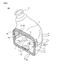
まず、図3(A)に示す、実験装置200を作製した。
実験装置200は、一端が開口され、他端が閉じられた、円筒状の筐体21を備えている。筐体21は、樹脂製である。
筐体21は、2つの固定部23によって固定されている。2つの固定部23は、筐体21の相対する位置に固定されている。
筐体21の内側面に、歪みセンサ24が貼り付けられている。より具体的には、歪みセンサ24は、長手方向と短手方向とを有し、かつ、長手方向の両端に第1端24aと第2端24bとを有する冊状である。歪みセンサ24は、長手方向を筐体21の開口の縁に沿う方向にし、かつ、相対的に、第1端14aを一方の固定部23の近くにし、第2端24bを一方の固定部13の遠くにして、筐体21の内側面に貼り付けられている。
図3(A)において、まず、筐体21の外側面のA1部分を押圧した。歪みセンサ24は、良好に、大きな信号を発生させた。
次に、筐体21の外側面のA1部分とA2部分の両方を押圧した。歪みセンサ24は、良好に、大きな信号を発生させた。
次に、筐体21の外底部B部分を押圧した。しかしながら、歪みセンサ24は、非常に小さな信号しか発生させなかった。
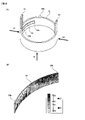
図3(B)に、筐体21の外底部B部分を押圧したときの、歪みセンサ24に発生する、伸びと縮みを示す。なお、図3(B)は、シミュレーションによって取得したものである。
図3(B)から分かるように、歪みセンサ14の第1端14aでは、下方領域で伸びが発生し、上方領域で縮みが発生するのに対し、歪みセンサ14の第2端14bでは、下方領域で縮みが発生している。この結果、歪みセンサ14内で信号が相殺され、歪みセンサ14が、小さな信号しか発生しなかったものと考えられる。
このように、歪みセンサ24は、筐体21の外側面のA1部分や、A1部分およびA2部分を押圧したときには、良好に大きな信号を発生させるが、筐体21の外底部B部分を押圧したときには、小さな信号しか発生させなかった。以上より、本発明の有効性が確認できた。
(実験2)
次に、本発明における、筐体(特に第2筐体)の適正な開口の大きさ、固定部の適正な位置、固定部の適正な個数を調べるために、次の実験2を実施した。
次に、本発明における、筐体(特に第2筐体)の適正な開口の大きさ、固定部の適正な位置、固定部の適正な個数を調べるために、次の実験2を実施した。
まず、図4(A)に示す、実験装置300を作製した。
実験装置300は、一端が開口され、他端が閉じられた、円筒状の筐体31を備えている。なお、実験装置300は、筐体31として、開口の直径(φ)が、20mm、28mm、40mmからなる、3種類を作製した。
筐体31の内側面に、歪みセンサ34が貼り付けられている。より具体的には、歪みセンサ34は、長手方向と短手方向とを有し、かつ、長手方向の両端に第1端34aと第2端34bとを有する冊状である。歪みセンサ34は、長手方向を筐体31の開口の縁に沿う方向にして、筐体31の内側面に貼り付けられている。なお、実験2においては、歪みセンサ34の長手方向の長さを、15mmとした。
筐体31には、1つの固定部33が設けられている。固定部33を設ける位置は可変になっており、歪みセンサ34と固定部33との相対的な位置関係を、変更できるようになっている。
図4(A)では、固定部33を、歪みセンサ34の第1端34aのところに固定している。このときの角度(以下において「拘束位置の角度」と呼ぶ場合がある)を、0°とする。そして、時計回りに固定部33の位置を移動させることにより、拘束位置の角度は、90°、180°、270°というように大きくなるものとする。
なお、固定部33の幅は、歪みセンサ34の適正な作動を妨げないためには、できるだけ小さいことが好ましい。しかしながら、本発明をイヤフォン100などに具現化させた場合には、固定部33の幅に相当する爪部12の幅は、第1筐体1と第2筐体2とを強固に固定するための強度が必要であり、ある程度の大きさが必要になる。たとえば、イヤフォン100においては、爪部12の幅は、数mmの大きさが必要になる。そこで、実験2においては、固定部33の幅を5mmとした。
3種類の実験装置300において、固定部33の位置をずらしながら、実験装置300の外底面を押圧したときの歪みセンサ34が発生させる出力の大きさを測定した。図4(B)に、その結果を示す。
図4(B)から分かるように、筐体31の開口の直径を20mmにしたものは、固定部33の位置にかかわらず、5を少し上回る大きさの信号を出力した。なお、出力の数値は、比較する上での相対的な大きさを示している。この結果、筐体31の開口の直径が20mmの場合は、本発明を適用するには、開口の直径が小さ過ぎることが分かった。
一方、筐体31の開口の直径を28mmにしたものは、固定部33の位置を移動させることにより、歪みセンサ34の出力の大きさが、周期的に変化した。そして、拘束位置の角度が、0°、120°のときに、歪みセンサ34の出力の大きさが0になった。
また、筐体31の開口の直径を40mmにしたものも、固定部33の位置を移動させることにより、歪みセンサ34の出力の大きさが、周期的に変化した。そして、拘束位置の角度が、約105°のときに、歪みセンサ34の出力の大きさが0になった。
以上のように、筐体31の開口の直径が、28mm以上、40mm以下の場合において、本発明を良好に適用し得ることが確認できた。
また、たとえば、筐体31の開口の直径が28mmのときには、拘束位置の角度が、0°、120°、240°である3か所に固定部33を設ければ、筐体の外底部を押圧しても歪みセンサ34は信号を出力せず、かつ、第1筐体と第筐体を強固に固定できることが分かった。
以上、実施形態にかかるイヤフォン100について説明した。しかしながら、本発明が上述した内容に限定されることはなく、発明の趣旨に沿って種々の変更をなすことができる。
たとえば、実施形態においては、電子機器としてイヤフォンを示したが、電子機器はイヤフォンには限定されず、補聴器、ヘッドセットなどであってもよい。また、電子機器は、音声、音楽などに関するものには限定されず、筐体と歪みセンサとを備えていれば、あらゆる種類の電子機器に本発明を適用することができる。
また、イヤフォン100においては、第1筐体1に耳孔挿入部5が設けられていたが、これに代えて、筐体3(特に第1筐体1)が耳孔挿入部を構成してもよい。
また、イヤフォン100においては、第1筐体1に係止部8を設け、第2筐体2に爪部12を設けていたが、これを逆にして、第1筐体1に爪部12を設け、第2筐体2に係止部8を設けてもよい。
本発明の一実施態様にかかる電子機器は、「課題を解決するための手段」の欄に記載したとおりである。
この電子機器において、筐体の内部に、発音体が設けられ、イヤフォン、補聴器、ヘッドセットから選ばれる少なくとも1つが構成されることも好ましい。これらの電子機器においては、特に本発明が有用だからである。この場合において、第1開口が設けられているのと反対側である、第1筐体の他方側に、人間の耳孔に挿入可能な、耳孔挿入部が設けられるか、または、第1筐体が、人間の耳孔に挿入可能な、耳孔挿入部を構成することも好ましい。
歪みセンサが、発音体を兼ね、発音体の機能を有していることも好ましい。この場合には、必要な部品点数を削減できるとともに、製造が簡略化できて生産性が向上する
第2開口が設けられているのと反対側である、第2筐体の他方側が閉じていることも好ましい。この場合には、筐体の中空を、耳孔挿入部を除いて、密閉することができる。
固定部の数が、2つ、または、3つであることも好ましい。この場合には、筐体の外底部を押圧しても、歪みセンサが信号を出力せず、あるいは小さな信号しか出力しないようにしつつ、第1筐体と第2筐体とを強固に固定することができる。
固定部が、第1筐体および第2筐体の一方に形成された、爪部と、第1筐体および第2筐体の他方に形成された、爪部を係止可能な係止部とで構成されることも好ましい。この場合には、第1筐体と第2筐体とを強固に固定することができる。
爪部の幅が、5mm以下であることも好ましい。この場合には、固定部が歪みセンサの適正な作動を阻害することなく、第1筐体と第2筐体とを強固に固定することができる。
第2開口の開口方向にみた、歪みセンサが貼り付けられている領域の第2筐体の断面において、内壁の形状が、円形、または、楕円形であり、円形の直径、または、楕円形の長軸の長さが、28mm以上、40mm以下であることも好ましい。この場合には、筐体の外底部を押圧しても、歪みセンサが信号を出力せず、あるいは小さな信号しか出力しない電子機器を提供することができる。
外部の本体電子機器に、有線、または、無線で接続され、歪みセンサで取得した信号を、本体電子機器に送信することも好ましい。この場合には、筐体の外側面を押圧することにより、本体電子機器を制御することができる。本体電子機器は、たとえば、スマートフォン、タブレット端末、パーソナルコンピュータ、録音再生装置、ビデオ再生装置、ラジオ、テレビなどである。
1・・・第1筐体
2・・・第2筐体
3・・・筐体
4・・・第1開口
5・・・耳孔挿入部
6・・・側面
6a・・・内側面
6b・・・外側面
7・・・天面
7a・・・内天面
7b・・・外天面
8・・・係止部
8a・・・貫通孔
8b・・・係止梁
9・・・第2開口
10・・・底面
10a・・・内底面
10b・・・外底面
11・・・側面
11a・・・内側面
11b・・・外側面
12・・・爪部
12a・・・柱部
12b・・・爪
13・・・固定部
14・・・歪みセンサ
14a・・・第1端
14b・・・第2端
2・・・第2筐体
3・・・筐体
4・・・第1開口
5・・・耳孔挿入部
6・・・側面
6a・・・内側面
6b・・・外側面
7・・・天面
7a・・・内天面
7b・・・外天面
8・・・係止部
8a・・・貫通孔
8b・・・係止梁
9・・・第2開口
10・・・底面
10a・・・内底面
10b・・・外底面
11・・・側面
11a・・・内側面
11b・・・外側面
12・・・爪部
12a・・・柱部
12b・・・爪
13・・・固定部
14・・・歪みセンサ
14a・・・第1端
14b・・・第2端
Claims (11)
- 少なくとも、第1筐体と、第2筐体とを含む筐体と、
前記筐体の内壁に貼り付けられた、歪みセンサと、を備えた電子機器であって、
前記第1筐体は、一方側が第1開口によって開口され、
前記第2筐体は、一方側が第2開口によって開口され、
前記第1筐体と前記第2筐体とは、前記第1開口と前記第2開口とを向かい合わせにした状態で固定することにより、前記筐体を構成し、
前記第1筐体と前記第2筐体とは、2つ以上の固定部で固定され、
前記歪みセンサは、長手方向と短手方向とを有し、かつ、前記長手方向の両端に第1端と第2端とを有する冊状であり、
前記歪みセンサは、前記長手方向を前記第2開口の縁に沿う方向にし、かつ、相対的に、前記第1端を前記固定部の近くにし、前記第2端を前記固定部の遠くにして、前記第2筐体の内壁に貼り付けられた、
電子機器。 - 前記筐体の内部に、発音体が設けられ、
イヤフォン、補聴器、ヘッドセットから選ばれる少なくとも1つが構成された、
請求項1に記載された電子機器。 - 前記第1開口が設けられているのと反対側である、前記第1筐体の他方側に、人間の耳孔に挿入可能な、耳孔挿入部が設けられるか、または、前記第1筐体が、人間の耳孔に挿入可能な、耳孔挿入部を構成する、
請求項2に記載された電子機器。 - 前記歪みセンサが、前記発音体を兼ね、前記発音体の機能を有している、
請求項2または3に記載された電子機器。 - 前記第2開口が設けられているのと反対側である、前記第2筐体の他方側が、閉じている、
請求項1ないし4のいずれか1項に記載された電子機器。 - 前記固定部の数が、2つ、または、3つである、
請求項1ないし5のいずれか1項に記載された電子機器。 - 前記固定部が、前記第1筐体および前記第2筐体の一方に形成された、爪部と、前記第1筐体および前記第2筐体の他方に形成された、前記爪部を係止可能な係止部と、で構成された、
請求項1ないし6のいずれか1項に記載された電子機器。 - 前記爪部の幅が、5mm以下である、
請求項7に記載された電子機器。 - 前記第2開口の開口方向にみた、前記歪みセンサが貼り付けられている領域の前記第2筐体の断面において、前記内壁の形状が、円形、または、楕円形であり、
前記円形の直径、または、前記楕円形の長軸の長さが、28mm以上、40mm以下である、
請求項1ないし8のいずれか1項に記載された電子機器。 - 外部の本体電子機器に、有線、または、無線で接続され、
前記歪みセンサで取得した信号を、前記本体電子機器に送信する、
請求項1ないし9のいずれか1項に記載された電子機器。 - 前記本体電子機器が、スマートフォン、タブレット端末、パーソナルコンピュータ、録音再生装置、ビデオ再生装置、ラジオ、テレビから選ばれる、少なくとも1つである、
請求項10に記載された電子機器。
Priority Applications (3)
| Application Number | Priority Date | Filing Date | Title |
|---|---|---|---|
| CN202280004532.5A CN115699805B (zh) | 2021-03-18 | 2022-02-28 | 电子设备 |
| JP2022545342A JP7151949B1 (ja) | 2021-03-18 | 2022-02-28 | 電子機器 |
| US18/047,390 US12072230B2 (en) | 2021-03-18 | 2022-10-18 | Electronic device |
Applications Claiming Priority (2)
| Application Number | Priority Date | Filing Date | Title |
|---|---|---|---|
| JP2021-045237 | 2021-03-18 | ||
| JP2021045237 | 2021-03-18 |
Related Child Applications (1)
| Application Number | Title | Priority Date | Filing Date |
|---|---|---|---|
| US18/047,390 Continuation US12072230B2 (en) | 2021-03-18 | 2022-10-18 | Electronic device |
Publications (1)
| Publication Number | Publication Date |
|---|---|
| WO2022196332A1 true WO2022196332A1 (ja) | 2022-09-22 |
Family
ID=83321460
Family Applications (1)
| Application Number | Title | Priority Date | Filing Date |
|---|---|---|---|
| PCT/JP2022/008474 Ceased WO2022196332A1 (ja) | 2021-03-18 | 2022-02-28 | 電子機器 |
Country Status (4)
| Country | Link |
|---|---|
| US (1) | US12072230B2 (ja) |
| JP (1) | JP7151949B1 (ja) |
| CN (1) | CN115699805B (ja) |
| WO (1) | WO2022196332A1 (ja) |
Citations (2)
| Publication number | Priority date | Publication date | Assignee | Title |
|---|---|---|---|---|
| JP2018534844A (ja) * | 2015-09-28 | 2018-11-22 | アップル インコーポレイテッドApple Inc. | 近接センサを備えた無線イヤーバッド |
| JP2020150320A (ja) * | 2019-03-11 | 2020-09-17 | Necプラットフォームズ株式会社 | イヤホン、イヤホンの制御装置、およびイヤホンの制御方法 |
Family Cites Families (19)
| Publication number | Priority date | Publication date | Assignee | Title |
|---|---|---|---|---|
| JP3321532B2 (ja) | 1996-09-30 | 2002-09-03 | シャープ株式会社 | 振動検出装置 |
| JP2002262377A (ja) | 2001-02-28 | 2002-09-13 | Taiyo Yuden Co Ltd | 骨導ピックアップ素子及びそのユニット |
| EP2696163B1 (en) | 2011-04-08 | 2018-05-23 | Murata Manufacturing Co., Ltd. | Displacement sensor, displacement detecting apparatus, and operation device |
| US9201528B2 (en) * | 2011-06-07 | 2015-12-01 | Stmicroelectronics Sa | Method of manufacturing a vibratory actuator for a touch panel with haptic feedback |
| WO2013157508A1 (ja) * | 2012-04-17 | 2013-10-24 | 株式会社村田製作所 | 押圧力センサ |
| DE102015114242A1 (de) * | 2015-08-27 | 2017-03-02 | USound GmbH | MEMS-Lautsprecher mit Positionssensor |
| JP6723631B2 (ja) * | 2016-09-16 | 2020-07-15 | アルプスアルパイン株式会社 | 操作装置 |
| JP2018115958A (ja) * | 2017-01-18 | 2018-07-26 | 住友電気工業株式会社 | 歪センサ |
| US10129623B2 (en) * | 2017-03-15 | 2018-11-13 | Microsoft Technology Licensing, Llc | Electronic device having covering substrate carrying acoustic transducer and related technology |
| JP6631761B2 (ja) * | 2017-08-21 | 2020-01-15 | 株式会社村田製作所 | 押圧センサ及び電子機器 |
| JP6981178B2 (ja) | 2017-11-01 | 2021-12-15 | ヤマハ株式会社 | トランスデューサ |
| US10659866B2 (en) * | 2018-09-14 | 2020-05-19 | Apple Inc. | Elastomeric pressure transduction based user interface |
| US11348567B2 (en) * | 2019-02-25 | 2022-05-31 | Qualcomm Incorporated | Feedback control for display as sound emitter |
| CN111050243A (zh) * | 2019-12-06 | 2020-04-21 | 东莞微感电子技术有限公司 | 耳机及其控制方法 |
| CN112492435B (zh) * | 2020-11-06 | 2023-03-10 | 珠海普林芯驰科技有限公司 | 侧压式电容感应装置及其工作方法、电子设备 |
| US10993014B1 (en) * | 2020-12-21 | 2021-04-27 | Airtouch (Shanghai) Intelligent Technology Co.,Ltd | Integrated circuit packages in headphones and method for forming and operating the same |
| CN116156373B (zh) * | 2021-04-08 | 2023-11-14 | 荣耀终端有限公司 | 耳机 |
| WO2023022863A1 (en) * | 2021-08-19 | 2023-02-23 | Apple Inc. | Flexible speakers |
| CN114993526B (zh) * | 2022-05-05 | 2025-06-10 | 上海润势科技有限公司 | 一种可实现多方位感应的压力传感器及电子设备 |
-
2022
- 2022-02-28 JP JP2022545342A patent/JP7151949B1/ja active Active
- 2022-02-28 CN CN202280004532.5A patent/CN115699805B/zh active Active
- 2022-02-28 WO PCT/JP2022/008474 patent/WO2022196332A1/ja not_active Ceased
- 2022-10-18 US US18/047,390 patent/US12072230B2/en active Active
Patent Citations (2)
| Publication number | Priority date | Publication date | Assignee | Title |
|---|---|---|---|---|
| JP2018534844A (ja) * | 2015-09-28 | 2018-11-22 | アップル インコーポレイテッドApple Inc. | 近接センサを備えた無線イヤーバッド |
| JP2020150320A (ja) * | 2019-03-11 | 2020-09-17 | Necプラットフォームズ株式会社 | イヤホン、イヤホンの制御装置、およびイヤホンの制御方法 |
Also Published As
| Publication number | Publication date |
|---|---|
| US20230116596A1 (en) | 2023-04-13 |
| JP7151949B1 (ja) | 2022-10-12 |
| JPWO2022196332A1 (ja) | 2022-09-22 |
| CN115699805B (zh) | 2026-03-27 |
| US12072230B2 (en) | 2024-08-27 |
| CN115699805A (zh) | 2023-02-03 |
Similar Documents
| Publication | Publication Date | Title |
|---|---|---|
| US12501202B2 (en) | Microphone module and electronic device comprising microphone module | |
| US10397685B2 (en) | Earphone | |
| CN101141040B (zh) | 插头、声音输入和输出装置以及噪声消除系统 | |
| EP3906702B1 (en) | Systems and methods for unconstrained battery spring tab assemblies for in-ear headphone | |
| WO2016206764A1 (en) | Noise cancellation system, headset and electronic device | |
| KR20090016738A (ko) | 자동 홀딩 케이블 | |
| CN101366320A (zh) | 磁致伸缩装置 | |
| US20160198248A1 (en) | Sound Generator | |
| JP7151949B1 (ja) | 電子機器 | |
| CN211296899U (zh) | 表体和可穿戴设备 | |
| US20220141569A1 (en) | Multi-mic earphone design and assembly | |
| CN109788397A (zh) | 电子装置 | |
| US9497554B2 (en) | Flex-based connector for hearing aid | |
| US12520073B2 (en) | Electronic device including speaker | |
| KR102883570B1 (ko) | 마이크 모듈을 포함하는 전자 장치 | |
| KR102848190B1 (ko) | 연결 단자 및 센서를 포함하는 오디오 전자 장치 | |
| KR20210057152A (ko) | 분산 모드 스피커용 강화 액추에이터 | |
| JP2005167530A (ja) | スピーカ装置 | |
| JP4245462B2 (ja) | スピーカ装置 | |
| JP2019004396A (ja) | イヤホン | |
| KR102489062B1 (ko) | 능동 노이즈 저감 음향출력 장치 | |
| JPH0110060Y2 (ja) | ||
| CN113016193B (zh) | 耳机 | |
| US20180317032A1 (en) | Method for producing a supporting frame of a hearing aid, supporting frame and hearing aid | |
| JP2005086417A (ja) | イヤホンコード |
Legal Events
| Date | Code | Title | Description |
|---|---|---|---|
| ENP | Entry into the national phase |
Ref document number: 2022545342 Country of ref document: JP Kind code of ref document: A |
|
| 121 | Ep: the epo has been informed by wipo that ep was designated in this application |
Ref document number: 22771086 Country of ref document: EP Kind code of ref document: A1 |
|
| NENP | Non-entry into the national phase |
Ref country code: DE |
|
| 122 | Ep: pct application non-entry in european phase |
Ref document number: 22771086 Country of ref document: EP Kind code of ref document: A1 |