WO2022195867A1 - 電磁波ノイズ抑制シートおよびその製造方法 - Google Patents
電磁波ノイズ抑制シートおよびその製造方法 Download PDFInfo
- Publication number
- WO2022195867A1 WO2022195867A1 PCT/JP2021/011466 JP2021011466W WO2022195867A1 WO 2022195867 A1 WO2022195867 A1 WO 2022195867A1 JP 2021011466 W JP2021011466 W JP 2021011466W WO 2022195867 A1 WO2022195867 A1 WO 2022195867A1
- Authority
- WO
- WIPO (PCT)
- Prior art keywords
- layer
- noise suppression
- electromagnetic noise
- dispersion
- less
- Prior art date
Links
- 238000004519 manufacturing process Methods 0.000 title claims description 20
- 239000002041 carbon nanotube Substances 0.000 claims abstract description 125
- OKTJSMMVPCPJKN-UHFFFAOYSA-N Carbon Chemical compound [C] OKTJSMMVPCPJKN-UHFFFAOYSA-N 0.000 claims abstract description 87
- 229910021393 carbon nanotube Inorganic materials 0.000 claims abstract description 84
- 229920002134 Carboxymethyl cellulose Polymers 0.000 claims abstract description 81
- 235000010948 carboxy methyl cellulose Nutrition 0.000 claims abstract description 80
- 239000001768 carboxy methyl cellulose Substances 0.000 claims abstract description 79
- 239000008112 carboxymethyl-cellulose Substances 0.000 claims abstract description 79
- 230000001629 suppression Effects 0.000 claims description 76
- 239000006185 dispersion Substances 0.000 claims description 73
- 239000007788 liquid Substances 0.000 claims description 66
- 238000000034 method Methods 0.000 claims description 52
- XLYOFNOQVPJJNP-UHFFFAOYSA-N water Substances O XLYOFNOQVPJJNP-UHFFFAOYSA-N 0.000 claims description 23
- 239000002270 dispersing agent Substances 0.000 claims description 11
- 239000002048 multi walled nanotube Substances 0.000 claims description 9
- 238000001035 drying Methods 0.000 claims description 8
- 239000010410 layer Substances 0.000 description 120
- 239000011247 coating layer Substances 0.000 description 66
- 239000000123 paper Substances 0.000 description 45
- 239000000203 mixture Substances 0.000 description 18
- 238000000889 atomisation Methods 0.000 description 15
- 239000012790 adhesive layer Substances 0.000 description 14
- -1 polyethylene terephthalate Polymers 0.000 description 14
- 238000002360 preparation method Methods 0.000 description 14
- 239000003795 chemical substances by application Substances 0.000 description 12
- 238000004513 sizing Methods 0.000 description 11
- 238000000576 coating method Methods 0.000 description 10
- 239000002562 thickening agent Substances 0.000 description 10
- 229920001131 Pulp (paper) Polymers 0.000 description 9
- 230000005540 biological transmission Effects 0.000 description 8
- 239000011248 coating agent Substances 0.000 description 8
- 239000000463 material Substances 0.000 description 8
- 229920005989 resin Polymers 0.000 description 8
- 239000011347 resin Substances 0.000 description 8
- 239000000835 fiber Substances 0.000 description 7
- 239000000049 pigment Substances 0.000 description 7
- 239000000654 additive Substances 0.000 description 6
- 230000007423 decrease Effects 0.000 description 6
- 230000008569 process Effects 0.000 description 6
- 239000000126 substance Substances 0.000 description 6
- 238000005259 measurement Methods 0.000 description 5
- 230000004048 modification Effects 0.000 description 5
- 238000012986 modification Methods 0.000 description 5
- 229920000139 polyethylene terephthalate Polymers 0.000 description 5
- 239000005020 polyethylene terephthalate Substances 0.000 description 5
- 239000004372 Polyvinyl alcohol Substances 0.000 description 4
- 238000004040 coloring Methods 0.000 description 4
- 239000003822 epoxy resin Substances 0.000 description 4
- 238000011156 evaluation Methods 0.000 description 4
- 239000012535 impurity Substances 0.000 description 4
- 229920000647 polyepoxide Polymers 0.000 description 4
- 229920002451 polyvinyl alcohol Polymers 0.000 description 4
- 238000012545 processing Methods 0.000 description 4
- 239000002904 solvent Substances 0.000 description 4
- 241000284156 Clerodendrum quadriloculare Species 0.000 description 3
- 239000004698 Polyethylene Substances 0.000 description 3
- 239000002253 acid Substances 0.000 description 3
- 230000015572 biosynthetic process Effects 0.000 description 3
- 229920001577 copolymer Polymers 0.000 description 3
- 239000000975 dye Substances 0.000 description 3
- 238000006266 etherification reaction Methods 0.000 description 3
- 229910021389 graphene Inorganic materials 0.000 description 3
- 239000003973 paint Substances 0.000 description 3
- 229920000573 polyethylene Polymers 0.000 description 3
- 229920002050 silicone resin Polymers 0.000 description 3
- 239000002109 single walled nanotube Substances 0.000 description 3
- KXGFMDJXCMQABM-UHFFFAOYSA-N 2-methoxy-6-methylphenol Chemical compound [CH]OC1=CC=CC([CH])=C1O KXGFMDJXCMQABM-UHFFFAOYSA-N 0.000 description 2
- 229920000178 Acrylic resin Polymers 0.000 description 2
- 239000004925 Acrylic resin Substances 0.000 description 2
- KAKZBPTYRLMSJV-UHFFFAOYSA-N Butadiene Chemical compound C=CC=C KAKZBPTYRLMSJV-UHFFFAOYSA-N 0.000 description 2
- VTYYLEPIZMXCLO-UHFFFAOYSA-L Calcium carbonate Chemical compound [Ca+2].[O-]C([O-])=O VTYYLEPIZMXCLO-UHFFFAOYSA-L 0.000 description 2
- YCKRFDGAMUMZLT-UHFFFAOYSA-N Fluorine atom Chemical compound [F] YCKRFDGAMUMZLT-UHFFFAOYSA-N 0.000 description 2
- VZCYOOQTPOCHFL-OWOJBTEDSA-N Fumaric acid Chemical compound OC(=O)\C=C\C(O)=O VZCYOOQTPOCHFL-OWOJBTEDSA-N 0.000 description 2
- 239000004640 Melamine resin Substances 0.000 description 2
- 229920000877 Melamine resin Polymers 0.000 description 2
- 229920002845 Poly(methacrylic acid) Polymers 0.000 description 2
- 239000004642 Polyimide Substances 0.000 description 2
- 239000004721 Polyphenylene oxide Substances 0.000 description 2
- 239000004743 Polypropylene Substances 0.000 description 2
- XUIMIQQOPSSXEZ-UHFFFAOYSA-N Silicon Chemical compound [Si] XUIMIQQOPSSXEZ-UHFFFAOYSA-N 0.000 description 2
- PPBRXRYQALVLMV-UHFFFAOYSA-N Styrene Chemical compound C=CC1=CC=CC=C1 PPBRXRYQALVLMV-UHFFFAOYSA-N 0.000 description 2
- 229920001807 Urea-formaldehyde Polymers 0.000 description 2
- XTXRWKRVRITETP-UHFFFAOYSA-N Vinyl acetate Chemical compound CC(=O)OC=C XTXRWKRVRITETP-UHFFFAOYSA-N 0.000 description 2
- BZHJMEDXRYGGRV-UHFFFAOYSA-N Vinyl chloride Chemical compound ClC=C BZHJMEDXRYGGRV-UHFFFAOYSA-N 0.000 description 2
- NIXOWILDQLNWCW-UHFFFAOYSA-N acrylic acid group Chemical group C(C=C)(=O)O NIXOWILDQLNWCW-UHFFFAOYSA-N 0.000 description 2
- 239000000853 adhesive Substances 0.000 description 2
- 230000001070 adhesive effect Effects 0.000 description 2
- 229910052783 alkali metal Inorganic materials 0.000 description 2
- 239000002518 antifoaming agent Substances 0.000 description 2
- 239000012752 auxiliary agent Substances 0.000 description 2
- 230000015556 catabolic process Effects 0.000 description 2
- 238000005229 chemical vapour deposition Methods 0.000 description 2
- 230000000694 effects Effects 0.000 description 2
- 239000007850 fluorescent dye Substances 0.000 description 2
- 239000011737 fluorine Substances 0.000 description 2
- 229910052731 fluorine Inorganic materials 0.000 description 2
- 239000007849 furan resin Substances 0.000 description 2
- 238000005227 gel permeation chromatography Methods 0.000 description 2
- 238000007602 hot air drying Methods 0.000 description 2
- 238000007603 infrared drying Methods 0.000 description 2
- 150000002484 inorganic compounds Chemical class 0.000 description 2
- 229910010272 inorganic material Inorganic materials 0.000 description 2
- 239000002655 kraft paper Substances 0.000 description 2
- 239000011259 mixed solution Substances 0.000 description 2
- 238000002156 mixing Methods 0.000 description 2
- 239000013054 paper strength agent Substances 0.000 description 2
- 230000035515 penetration Effects 0.000 description 2
- 229920001568 phenolic resin Polymers 0.000 description 2
- 239000005011 phenolic resin Substances 0.000 description 2
- 229920003023 plastic Polymers 0.000 description 2
- 239000004033 plastic Substances 0.000 description 2
- 229920002492 poly(sulfone) Polymers 0.000 description 2
- 229920002401 polyacrylamide Polymers 0.000 description 2
- 239000004417 polycarbonate Substances 0.000 description 2
- 229920000515 polycarbonate Polymers 0.000 description 2
- 229920000728 polyester Polymers 0.000 description 2
- 229920001721 polyimide Polymers 0.000 description 2
- 229920006380 polyphenylene oxide Polymers 0.000 description 2
- 229920001155 polypropylene Polymers 0.000 description 2
- 239000003755 preservative agent Substances 0.000 description 2
- 239000010703 silicon Substances 0.000 description 2
- 229910052710 silicon Inorganic materials 0.000 description 2
- 239000002002 slurry Substances 0.000 description 2
- 229920005792 styrene-acrylic resin Polymers 0.000 description 2
- 238000002411 thermogravimetry Methods 0.000 description 2
- 229920001169 thermoplastic Polymers 0.000 description 2
- 229920002803 thermoplastic polyurethane Polymers 0.000 description 2
- 239000004416 thermosoftening plastic Substances 0.000 description 2
- VZCYOOQTPOCHFL-UHFFFAOYSA-N trans-butenedioic acid Natural products OC(=O)C=CC(O)=O VZCYOOQTPOCHFL-UHFFFAOYSA-N 0.000 description 2
- 229920003169 water-soluble polymer Polymers 0.000 description 2
- NJVOHKFLBKQLIZ-UHFFFAOYSA-N (2-ethenylphenyl) prop-2-enoate Chemical compound C=CC(=O)OC1=CC=CC=C1C=C NJVOHKFLBKQLIZ-UHFFFAOYSA-N 0.000 description 1
- NBOCQTNZUPTTEI-UHFFFAOYSA-N 4-[4-(hydrazinesulfonyl)phenoxy]benzenesulfonohydrazide Chemical compound C1=CC(S(=O)(=O)NN)=CC=C1OC1=CC=C(S(=O)(=O)NN)C=C1 NBOCQTNZUPTTEI-UHFFFAOYSA-N 0.000 description 1
- 102100031260 Acyl-coenzyme A thioesterase THEM4 Human genes 0.000 description 1
- 241000609240 Ambelania acida Species 0.000 description 1
- 235000017166 Bambusa arundinacea Nutrition 0.000 description 1
- 235000017491 Bambusa tulda Nutrition 0.000 description 1
- 229920000742 Cotton Polymers 0.000 description 1
- 229920000219 Ethylene vinyl alcohol Polymers 0.000 description 1
- 241000219146 Gossypium Species 0.000 description 1
- 240000000797 Hibiscus cannabinus Species 0.000 description 1
- 101000638510 Homo sapiens Acyl-coenzyme A thioesterase THEM4 Proteins 0.000 description 1
- 229920002153 Hydroxypropyl cellulose Polymers 0.000 description 1
- CERQOIWHTDAKMF-UHFFFAOYSA-N Methacrylic acid Chemical compound CC(=C)C(O)=O CERQOIWHTDAKMF-UHFFFAOYSA-N 0.000 description 1
- 244000082204 Phyllostachys viridis Species 0.000 description 1
- 235000015334 Phyllostachys viridis Nutrition 0.000 description 1
- OFOBLEOULBTSOW-UHFFFAOYSA-N Propanedioic acid Natural products OC(=O)CC(O)=O OFOBLEOULBTSOW-UHFFFAOYSA-N 0.000 description 1
- 229920002472 Starch Polymers 0.000 description 1
- GWEVSGVZZGPLCZ-UHFFFAOYSA-N Titan oxide Chemical compound O=[Ti]=O GWEVSGVZZGPLCZ-UHFFFAOYSA-N 0.000 description 1
- 238000005411 Van der Waals force Methods 0.000 description 1
- 150000007513 acids Chemical class 0.000 description 1
- 230000000996 additive effect Effects 0.000 description 1
- 238000004220 aggregation Methods 0.000 description 1
- 230000002776 aggregation Effects 0.000 description 1
- DIZPMCHEQGEION-UHFFFAOYSA-H aluminium sulfate (anhydrous) Chemical compound [Al+3].[Al+3].[O-]S([O-])(=O)=O.[O-]S([O-])(=O)=O.[O-]S([O-])(=O)=O DIZPMCHEQGEION-UHFFFAOYSA-H 0.000 description 1
- 150000003863 ammonium salts Chemical class 0.000 description 1
- 239000003945 anionic surfactant Substances 0.000 description 1
- 238000001241 arc-discharge method Methods 0.000 description 1
- 239000010905 bagasse Substances 0.000 description 1
- 239000011425 bamboo Substances 0.000 description 1
- 239000002585 base Substances 0.000 description 1
- 238000005282 brightening Methods 0.000 description 1
- 239000004067 bulking agent Substances 0.000 description 1
- MTAZNLWOLGHBHU-UHFFFAOYSA-N butadiene-styrene rubber Chemical compound C=CC=C.C=CC1=CC=CC=C1 MTAZNLWOLGHBHU-UHFFFAOYSA-N 0.000 description 1
- 229910000019 calcium carbonate Inorganic materials 0.000 description 1
- 229910052799 carbon Inorganic materials 0.000 description 1
- 150000001735 carboxylic acids Chemical class 0.000 description 1
- 229920002678 cellulose Polymers 0.000 description 1
- 235000010980 cellulose Nutrition 0.000 description 1
- 229920006184 cellulose methylcellulose Polymers 0.000 description 1
- 239000000919 ceramic Substances 0.000 description 1
- 239000011153 ceramic matrix composite Substances 0.000 description 1
- 238000012710 chemistry, manufacturing and control Methods 0.000 description 1
- 229920006026 co-polymeric resin Polymers 0.000 description 1
- 239000000470 constituent Substances 0.000 description 1
- 238000011109 contamination Methods 0.000 description 1
- 239000000539 dimer Substances 0.000 description 1
- 238000007599 discharging Methods 0.000 description 1
- 239000012153 distilled water Substances 0.000 description 1
- 238000010292 electrical insulation Methods 0.000 description 1
- 150000002148 esters Chemical class 0.000 description 1
- 229920001038 ethylene copolymer Polymers 0.000 description 1
- 239000000945 filler Substances 0.000 description 1
- 239000012530 fluid Substances 0.000 description 1
- 239000001530 fumaric acid Substances 0.000 description 1
- 239000011086 glassine Substances 0.000 description 1
- JEGUKCSWCFPDGT-UHFFFAOYSA-N h2o hydrate Chemical compound O.O JEGUKCSWCFPDGT-UHFFFAOYSA-N 0.000 description 1
- 239000011121 hardwood Substances 0.000 description 1
- 239000001863 hydroxypropyl cellulose Substances 0.000 description 1
- 235000010977 hydroxypropyl cellulose Nutrition 0.000 description 1
- 239000001023 inorganic pigment Substances 0.000 description 1
- NLYAJNPCOHFWQQ-UHFFFAOYSA-N kaolin Chemical compound O.O.O=[Al]O[Si](=O)O[Si](=O)O[Al]=O NLYAJNPCOHFWQQ-UHFFFAOYSA-N 0.000 description 1
- 238000000608 laser ablation Methods 0.000 description 1
- 239000000314 lubricant Substances 0.000 description 1
- 230000014759 maintenance of location Effects 0.000 description 1
- VZCYOOQTPOCHFL-UPHRSURJSA-N maleic acid Chemical compound OC(=O)\C=C/C(O)=O VZCYOOQTPOCHFL-UPHRSURJSA-N 0.000 description 1
- 239000011976 maleic acid Substances 0.000 description 1
- 229920000609 methyl cellulose Polymers 0.000 description 1
- 239000001923 methylcellulose Substances 0.000 description 1
- 235000010981 methylcellulose Nutrition 0.000 description 1
- 230000007935 neutral effect Effects 0.000 description 1
- 239000004745 nonwoven fabric Substances 0.000 description 1
- 239000012860 organic pigment Substances 0.000 description 1
- 239000003960 organic solvent Substances 0.000 description 1
- 230000000704 physical effect Effects 0.000 description 1
- 230000002265 prevention Effects 0.000 description 1
- 230000009467 reduction Effects 0.000 description 1
- 238000001223 reverse osmosis Methods 0.000 description 1
- 239000011122 softwood Substances 0.000 description 1
- 239000008107 starch Substances 0.000 description 1
- 235000019698 starch Nutrition 0.000 description 1
- 238000003756 stirring Methods 0.000 description 1
- 229940014800 succinic anhydride Drugs 0.000 description 1
- 239000012209 synthetic fiber Substances 0.000 description 1
- 229920002994 synthetic fiber Polymers 0.000 description 1
- 229920003002 synthetic resin Polymers 0.000 description 1
- 239000000057 synthetic resin Substances 0.000 description 1
- 238000012360 testing method Methods 0.000 description 1
- OGIDPMRJRNCKJF-UHFFFAOYSA-N titanium oxide Inorganic materials [Ti]=O OGIDPMRJRNCKJF-UHFFFAOYSA-N 0.000 description 1
- 229910021642 ultra pure water Inorganic materials 0.000 description 1
- 239000012498 ultrapure water Substances 0.000 description 1
- 229920001567 vinyl ester resin Polymers 0.000 description 1
- 125000000391 vinyl group Chemical group [H]C([*])=C([H])[H] 0.000 description 1
- 239000001993 wax Substances 0.000 description 1
- 230000037303 wrinkles Effects 0.000 description 1
Images


Classifications
-
- H—ELECTRICITY
- H05—ELECTRIC TECHNIQUES NOT OTHERWISE PROVIDED FOR
- H05K—PRINTED CIRCUITS; CASINGS OR CONSTRUCTIONAL DETAILS OF ELECTRIC APPARATUS; MANUFACTURE OF ASSEMBLAGES OF ELECTRICAL COMPONENTS
- H05K9/00—Screening of apparatus or components against electric or magnetic fields
- H05K9/0073—Shielding materials
- H05K9/0081—Electromagnetic shielding materials, e.g. EMI, RFI shielding
- H05K9/009—Electromagnetic shielding materials, e.g. EMI, RFI shielding comprising electro-conductive fibres, e.g. metal fibres, carbon fibres, metallised textile fibres, electro-conductive mesh, woven, non-woven mat, fleece, cross-linked
-
- H—ELECTRICITY
- H05—ELECTRIC TECHNIQUES NOT OTHERWISE PROVIDED FOR
- H05K—PRINTED CIRCUITS; CASINGS OR CONSTRUCTIONAL DETAILS OF ELECTRIC APPARATUS; MANUFACTURE OF ASSEMBLAGES OF ELECTRICAL COMPONENTS
- H05K9/00—Screening of apparatus or components against electric or magnetic fields
- H05K9/0073—Shielding materials
- H05K9/0081—Electromagnetic shielding materials, e.g. EMI, RFI shielding
-
- C—CHEMISTRY; METALLURGY
- C01—INORGANIC CHEMISTRY
- C01B—NON-METALLIC ELEMENTS; COMPOUNDS THEREOF; METALLOIDS OR COMPOUNDS THEREOF NOT COVERED BY SUBCLASS C01C
- C01B32/00—Carbon; Compounds thereof
- C01B32/15—Nano-sized carbon materials
- C01B32/158—Carbon nanotubes
- C01B32/168—After-treatment
- C01B32/174—Derivatisation; Solubilisation; Dispersion in solvents
-
- H—ELECTRICITY
- H05—ELECTRIC TECHNIQUES NOT OTHERWISE PROVIDED FOR
- H05K—PRINTED CIRCUITS; CASINGS OR CONSTRUCTIONAL DETAILS OF ELECTRIC APPARATUS; MANUFACTURE OF ASSEMBLAGES OF ELECTRICAL COMPONENTS
- H05K7/00—Constructional details common to different types of electric apparatus
- H05K7/20—Modifications to facilitate cooling, ventilating, or heating
- H05K7/2039—Modifications to facilitate cooling, ventilating, or heating characterised by the heat transfer by conduction from the heat generating element to a dissipating body
- H05K7/20436—Inner thermal coupling elements in heat dissipating housings, e.g. protrusions or depressions integrally formed in the housing
- H05K7/20445—Inner thermal coupling elements in heat dissipating housings, e.g. protrusions or depressions integrally formed in the housing the coupling element being an additional piece, e.g. thermal standoff
- H05K7/20472—Sheet interfaces
- H05K7/20481—Sheet interfaces characterised by the material composition exhibiting specific thermal properties
Definitions
- the present invention relates to an electromagnetic noise suppression sheet and a manufacturing method thereof.
- a carbon nanotube has a structure that resembles a flat, flat graphene sheet rolled into a cylinder. Since carbon nanotubes have such a unique structure, they have various properties and are expected to be applied in a wide range of fields.
- Patent Literature 1 describes an electromagnetic wave suppressing sheet coated with multi-walled carbon nanotubes to a base material in an amount of 1 g/cm 2 or more.
- the electromagnetic wave suppression sheet as described above is used, for example, by being attached to an electronic device.
- Electronic devices tend to trap heat. Therefore, it is required to have high thermal conductivity as well as electromagnetic noise suppression performance. If the thermal conductivity is high, the heat of the electronic device can be efficiently dissipated.
- One aspect of the electromagnetic noise suppression sheet according to the present invention is comprising a first layer consisting essentially of carbon nanotubes and carboxymethyl cellulose; In the first layer, the ratio of the mass of the carboxymethyl cellulose to the mass of the carbon nanotubes is 1/5 or more and 3 or less.
- the ratio may be 1 or less.
- the ratio may be 1/3 or more.
- a surface resistivity of the first layer may be 60 ⁇ / ⁇ or less.
- a thickness of the first layer may be 2 ⁇ m or more.
- the carbon nanotubes may be multi-walled carbon nanotubes.
- a second layer provided with the first layer may be included.
- One aspect of the method for manufacturing an electromagnetic noise suppression sheet according to the present invention is preparing a dispersion containing carbon nanotubes, carboxymethyl cellulose, and water; drying the dispersion to form a first layer; including In the step of preparing the dispersion, using only the carboxymethyl cellulose as a dispersant, In the dispersion liquid, the ratio of the mass of the carboxymethylcellulose to the mass of the carbon nanotubes is 1/5 or more and 3 or less.
- the ratio may be 1 or less.
- the ratio may be 1/3 or more.
- a step of applying the dispersion to the second layer may be included before the step of forming the first layer.
- An electromagnetic noise suppression sheet includes a first layer substantially composed of carbon nanotubes and carboxymethyl cellulose, and in the first layer, the ratio of the mass of carboxymethyl cellulose to the mass of carbon nanotubes is 1. /5 or more and 3 or less, the electromagnetic wave noise suppression performance and thermal conductivity are high.
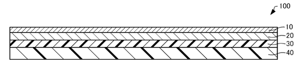
- FIG. 1 is a cross-sectional view schematically showing an electromagnetic noise suppression sheet according to this embodiment.
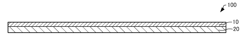
- FIG. 2 is a cross-sectional view schematically showing the electromagnetic noise suppression sheet according to this embodiment.
- FIG. 3 is a cross-sectional view schematically showing an electromagnetic noise suppression sheet according to this embodiment.
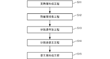
- FIG. 4 is a flow chart for explaining the method for manufacturing the electromagnetic noise suppression sheet according to this embodiment.
- FIG. 5 is a flow chart for explaining the method for manufacturing the electromagnetic noise suppression sheet according to this embodiment.
- FIG. 6 is a table showing the transmission attenuation rate of coated paper when changing the mass ratio of carbon nanotubes and carboxymethyl cellulose.
- FIG. 7 is a graph showing the transmission attenuation rate of coated paper with respect to frequency when the mass ratio of carbon nanotubes and carboxymethyl cellulose is changed.
- FIG. 8 is a table showing the transmission attenuation factor with respect to frequency when the thickness of the coated paper is changed.
- FIG. 9 is a graph showing the transmission attenuation factor of coated paper with respect to frequency when the thickness of the coated paper is changed.
- FIG. 10 is a table showing the transmission attenuation factor of coated paper when the number of passes is changed.
- FIG. 11 is a graph showing the transmission attenuation factor of coated paper with respect to frequency when the number of passes is changed.
- FIG. 1 is a cross-sectional view schematically showing an electromagnetic noise suppression sheet 100 according to this embodiment.
- the electromagnetic noise suppression sheet 100 has a sheet shape in which the length in the in-plane direction (the direction perpendicular to the thickness direction) is sufficiently long with respect to the thickness direction.
- the planar shape of the electromagnetic noise suppression sheet 100 is not particularly limited, it is rectangular, for example.
- the electromagnetic noise suppression sheet 100 includes, for example, a coating layer 10 as a first layer, a support layer 20 as a second layer, an adhesive layer 30, and a release layer 40, as shown in FIG.
- a coating layer 10 as a first layer
- a support layer 20 as a second layer
- an adhesive layer 30, and a release layer 40 as shown in FIG.
- each member will be described in order.
- Coating layer 1.1.1.1. Physical Properties The coating layer 10 is provided on the support layer 20 .
- the coating layer 10 is a layer coated on the support layer 20 .
- the surface resistivity of the coating layer 10 is, for example, 150 ⁇ / ⁇ or less, preferably 60 ⁇ / ⁇ or less, more preferably 50 ⁇ / ⁇ or less, and even more preferably 40 ⁇ / ⁇ or less.
- the surface resistivity of the coating layer 10 correlates with the electromagnetic noise suppression performance of the electromagnetic noise suppression sheet 100, and the lower the surface resistivity, the higher the electromagnetic noise suppression performance tends to be. If the surface resistivity of the coating layer 10 is 150 ⁇ / ⁇ or less, the electromagnetic wave noise suppressing performance can be enhanced.
- the surface resistivity of the coating layer 10 can be measured according to "JIS K 7194".
- the thickness of the coating layer 10 is, for example, 1.0 ⁇ m or more and 300 ⁇ m or less, preferably 2.0 ⁇ m or more and 250 ⁇ m or less, and more preferably 3.0 ⁇ m or more and 200 ⁇ m or less. If the thickness of the coating layer 10 is 1.0 ⁇ m or more, the surface resistivity of the coating layer 10 can be lowered. If the thickness of the coating layer 10 is 300 ⁇ m or less, the possibility of cracks occurring in the coating layer 10 can be reduced. The thickness of the coating layer 10 can be measured by SEM (Scanning Electron Microscope).
- the in-plane thermal conductivity of the coating layer 10 is, for example, 0.90 W/m ⁇ K or more, preferably 0.93 W/m ⁇ K or more, and more preferably 1.0 W/m ⁇ K. or more, and more preferably 1.3 W/m ⁇ K or more.
- the “thermal conductivity in the in-plane direction of the coating layer 10” is the thermal conductivity in the direction orthogonal to the thickness direction of the coating layer 10 (the stacking direction of the coating layer 10 and the support layer 20).
- thermal conductivity in the in-plane direction of the coating layer 10 is also simply referred to as "thermal conductivity of the coating layer 10".
- the thermal conductivity ⁇ can be calculated by the following formula (1), where ⁇ is the thermal diffusivity, C is the specific heat, and ⁇ is the density.
- the coating layer 10 includes carbon nanotubes (hereinafter also referred to as “CNT”) and carboxymethyl cellulose (hereinafter also referred to as “CMC”).
- the coating layer 10 is substantially composed of CNT and CMC.
- “Substantially composed of CNT and CMC” means when composed of CNT and CMC (when composed only of CNT and CMC), and when composed of CNT, CMC and other trace substances If and when “Other minor substances” are substances other than CNT and CMC, and the mass of these substances is 0.5% by mass or less with respect to the mass of the coating layer 10 .
- the “other trace substances” may be additives intentionally added when manufacturing the electromagnetic noise suppression sheet 100, or may be impurities mixed unintentionally.
- Carbon nanotube (CNT) The CNTs contained in the coating layer 10 are single-walled carbon nanotubes (SWCNTs) in which a single six-membered ring network (graphene sheet) made of carbon is wound in a cylindrical shape, and a plurality of graphenes.
- the sheet is a concentrically wound multi-walled carbon nanotube (MWCNT).
- the coating layer 10 may contain only one of SWCNTs and MWCNTs, or may contain both of them, but it preferably contains only MWCNTs in consideration of the dispersibility of CNTs. That is, the CNTs contained in the coating layer 10 are preferably MWCNTs. Both ends of the CNT may be closed or open.
- the CNTs as described above are produced in a preferred size by, for example, an arc discharge method, a laser ablation method, a CVD (Chemical Vapor Deposition) method, or the like.
- the CNTs contained in the coating layer 10 may be produced using any method.
- the diameter of the CNT is, for example, 1 nm or more and 100 nm or less, preferably 5 nm or more and 50 nm or less, more preferably 8 nm or more and 15 nm or less. If the diameter of the CNTs is 1 nm or more and 100 nm or less, it is possible to prepare a dispersion having good CNT dispersibility when forming the coating layer 10 .
- the diameter of CNTs can be measured by SEM.
- the fiber length of CNT is, for example, 0.5 ⁇ m or more and 50 ⁇ m or less, preferably 15 ⁇ m or more and 35 ⁇ m or less. If the fiber length of the CNTs is 0.5 ⁇ m or more and 50 ⁇ m or less, a dispersion having good dispersibility of the CNTs can be produced.
- the fiber length of CNT can be measured by SEM.
- the term "fiber length of CNT" refers to the length of CNTs bundled by van der Waals force, ie, the length of CNTs before being dispersed in a solvent.
- the BET specific surface area of CNT is, for example, 50 m 2 /g or more and 500 m 2 /g or less, preferably 100 m 2 /g or more and 300 m 2 /g or less. If the BET specific surface area of the CNTs is 50 m 2 /g or more and 500 m 2 /g or less, a dispersion liquid with good CNT dispersibility can be produced when forming the coating layer 10 .
- the "BET specific surface area” is a specific surface area measured by the BET (Brunauer Emmett Teller) method, and can be measured by an automatic specific surface area measuring device.
- the CNT content is, for example, 0.1% by mass or more and 10.0% by mass or less, preferably 0.5% by mass or more and 5.0% by mass or less. and more preferably 2.0% by mass or more and 4.0% by mass or less. If the CNT content is 0.1% by mass or more, the electromagnetic wave noise suppression performance can be enhanced. When the CNT content is 10.0% by mass or less, a dispersion having good CNT dispersibility can be produced when forming the coating layer 10 .
- Carboxymethylcellulose (CMC) CMC functions as a dispersant for dispersing the CNTs when forming the coating layer 10 .
- CMC Carboxymethylcellulose
- the term “dispersant” refers to an additive that disperses CNTs in water and contributes to prevention of aggregation and settling of CNTs.
- the weight average molecular weight of CMC is, for example, 5000 or more and 100000 or less, preferably 10000 or more and 60000 or less, more preferably 10000 or more and 35000 or less.
- the weight-average molecular weight of CMC is 5000 or more, CMC is easily entangled with CNTs, and the dispersibility of CNTs is improved.
- the weight-average molecular weight is preferably 100,000 or less.
- the "weight average molecular weight" in this specification means the polystyrene-equivalent weight average molecular weight measured by gel permeation chromatography (GPC).
- the degree of etherification of CMC is, for example, 0.6 or more and 1.2 or less, preferably 0.6 or more and 0.8 or less. If the degree of etherification of CMC is 0.6 or more and 1.2 or less, a dispersion having good CNT dispersibility can be produced.
- the CMC content is, for example, 0.1% by mass or more and 10.0% by mass or less, preferably 0.5% by mass or more and 5.0% by mass or less. and more preferably 2.0% by mass or more and 4.0% by mass or less.
- the ratio M CMC /M CNT can be measured by thermal gravimetric analysis (TGA).
- the coating layer 10 may contain various additives such as thickeners, preservatives, and pH adjusters, if necessary.
- the support layer 20 is provided on the adhesive layer 30 .
- a coating layer 10 is provided on the support layer 20 .
- the support layer 20 supports the coating layer 10 .
- the support layer 20 is, for example, a sheet containing pulp.
- the support layer 20 may be composed only of pulp.
- Examples of the pulp contained in the support layer 20 include chemical pulps such as LBKP (hardwood bleached kraft pulp) and NBKP (softwood bleached kraft pulp), GP (groundwood pulp), PGW (pressurized groundwood pulp), and RMP (refiner mechanical pulp). pulp), TMP (thermomechanical pulp), CTMP (chemithermomechanical pulp), CMP (chemi-mechanical pulp), CGP (chemigrand pulp), wood pulp such as DIP (deinked pulp), or kenaf , bagasse, bamboo, cotton and other non-wood pulps.
- the support layer 20 may contain only one type of these pulps, or may contain two or more types in an arbitrary ratio. Furthermore, the support layer 20 may contain synthetic fibers as long as the quality is not affected.
- the support layer 20 preferably contains LBKP.
- the content of LBKP in the support layer 20 is, for example, 70% by mass or more, preferably 90% by mass or more, and more preferably 100% by mass. If the content of LBKP is 70% by mass or more, the distortion of the support layer 20 can be reduced.
- the support layer 20 When the basis weight of the support layer 20 is 40 g/m 2 or less, the support layer 20 preferably contains NBKP.
- the content of NBKP in the support layer 20 is, for example, 30% by mass or less. If the content of NBKP is 30% by mass or less, smoothness and strength of the support layer 20 can be maintained.
- the support layer 20 may contain fillers, paper strength agents, sizing agents, bulking agents, retention aids, drainage improvers, aluminum sulfate, wet paper strength agents, coloring dyes, coloring pigments, fluorescent brightening agents, as necessary. It may contain various additives such as agents, pitch control agents, thickeners, preservatives, and pH adjusters.
- the material of the support layer 20 is not particularly limited as long as it can support the coating layer 10 .
- the support layer 20 may be a resin film such as a PET (polyethylene terephthalate) film, a non-woven fabric, or a synthetic paper made mainly from a synthetic resin.
- the adhesive layer 30 is provided on the release layer 40 .
- the adhesive layer 30 has adhesiveness.
- the material of the adhesive layer 30 is not particularly limited as long as it has adhesiveness. Examples include acid ester copolymer resins and vinyl acetate/ethylene copolymer resins.
- the release layer 40 is detachably provided on the adhesive layer 30 .
- the release layer 40 is peeled from the adhesive layer 30, and then the adhesive layer 30 is brought into contact with the external device, thereby attaching the electromagnetic noise suppression sheet 100 to the external device.
- the material of the release layer 40 is not particularly limited as long as it can be released from the adhesive layer 30.
- non-coated paper such as woodfree paper, general coated paper, coated paper such as art paper, glassine, etc. Examples include paper, films using polyethylene, polyethylene terephthalate, etc., and film-laminated paper.
- a release agent such as a silicone resin or a fluorine resin may be applied in a dry mass of about 0.1 g/m 2 to 3 g/m 2 and dried.
- the electromagnetic noise suppression sheet 100 may include an overcoat layer 50 as shown in FIG.
- the overcoat layer 50 is provided on the coating layer 10 .
- the overcoat layer 50 is an insulating layer that suppresses scratches on the coating layer 10 and imparts dielectric breakdown strength.
- the material of the overcoat layer 50 is not particularly limited, but examples include polyethylene terephthalate, polypropylene, vinyl chloride resin, fluorine resin, silicone resin, styrene-acrylic resin, acrylic resin, urethane resin, epoxy resin, and polyethylene wax. , polycarbonate, polyphenylene oxide, polysulfone, polyimide, thermoplastic polyester, phenolic resin, urea resin, epoxy resin, melamine resin, sialylphthalate resin, furan resin, silicon-based inorganic compounds, and the like.
- the overcoat layer 50 may contain only one of these, or may contain two or more of them in an arbitrary ratio.
- the overcoat layer 50 preferably has heat resistance.
- the thickness of the overcoat layer 50 is not particularly limited, it is, for example, 1 ⁇ m or more and 20 ⁇ m or less, preferably 2 ⁇ m or more and 10 ⁇ m or less. If the thickness of the overcoat layer 50 is 1 ⁇ m or more, it is possible to suppress scratches on the coating layer 10 and impart electrical insulation and dielectric breakdown strength. If the thickness of the overcoat layer 50 is 20 ⁇ m or less, cost reduction can be achieved.
- the electromagnetic noise suppression sheet 100 may not include the adhesive layer 30 and the release layer 40 as long as it includes the coating layer 10 and the support layer 20 as shown in FIG.
- the electromagnetic noise suppression sheet 100 may be composed only of the coating layer 10 and the support layer 20 .
- the electromagnetic noise suppression sheet 100 has electromagnetic noise suppression performance for suppressing electromagnetic noise.
- the electromagnetic noise suppression performance is evaluated by measuring the transmission attenuation rate Rtp [dB] by the microstrip line method. The higher the Rtp, the higher the electromagnetic noise suppression performance.
- FIG. 4 is a flow chart for explaining the manufacturing method of the electromagnetic noise suppression sheet 100 according to this embodiment.
- the method for manufacturing the electromagnetic noise suppression sheet 100 includes, for example, as shown in FIG. Step S12), a dispersion preparation step of preparing a dispersion containing CNTs, CMC, and water (step S13), and a dispersion application step of applying the dispersion to the support layer 20 (step S14). and a coating layer forming step (step S15) for forming the coating layer 10 by drying the dispersion.
- a dispersion preparation step of preparing a dispersion containing CNTs, CMC, and water step S13
- a dispersion application step of applying the dispersion to the support layer 20 step S14
- a coating layer forming step step S15 for forming the coating layer 10 by drying the dispersion.
- Support layer forming step (step S11) In the support layer forming step, for example, a slurry containing pulp but not containing CNTs is made into paper by a paper machine to form the support layer 20 .
- the slurry for forming the support layer 20 has a Canadian standard freeness (CSF) of, for example, 200 ml or more and 550 ml or less, preferably 250 ml or more and 500 ml or less.
- CSF is obtained by the method described in "JIS P 81821-2".
- the papermaking method of the support layer 20 is not particularly limited, but for example, a fourdrinier paper machine, a fourdrinier multi-layer paper machine, a cylinder paper machine, a multi-layer cylinder paper machine, a fourdrinier cylinder combination multi-layer paper machine, a twin wire paper machine. It is performed using various devices such as.
- the papermaking method may be acid papermaking or neutral papermaking.
- a sizing liquid containing a water-soluble polymer such as starch, polyvinyl alcohol, or polyacrylamide may be applied to the surface of the support layer 20 .
- a water-soluble polymer such as starch, polyvinyl alcohol, or polyacrylamide
- Sizing fluids include surface sizing agents such as, for example, styrenic sizing agents, styrene-acrylate sizing agents, olefinic sizing agents, alkylketene dimer sizing agents, alkenyl succinic anhydride sizing agents.
- the sizing liquid may contain auxiliary agents such as coloring pigments, coloring dyes, fluorescent dyes, and antifoaming agents.
- auxiliary agents such as coloring pigments, coloring dyes, fluorescent dyes, and antifoaming agents.
- Examples of the method of applying the size liquid include size press, gate roll coater, metering sizer, rod coater, and bar coater.
- the surface of the support layer 20 may be coated with a paint containing a pigment and an adhesive.
- a paint containing a pigment and an adhesive By applying the coating material, it is possible to suppress excessive penetration of the dispersion liquid into the support layer 20 when the dispersion liquid is applied to the support layer 20 .
- pigments used in paints include inorganic pigments such as kaolin, light calcium carbonate, titanium oxide and plastic pigments, and organic pigments such as plastic pigments.
- Adhesives used in coatings include, for example, various copolymer latexes such as styrene/butadiene, styrene/acrylic, vinyl acetate/acrylic, and butadiene/methyl methacrylic.
- the paint may contain auxiliary agents such as pH adjusters, antifoaming agents, dispersants, lubricants, printability improvers, thickeners, water retention agents, fluorescent dyes, color pigments, and color dyes.
- peeling layer adhesion step (step S12) In the release layer adhering step, the release layer 40 coated with the adhesive layer 30 and dried is adhered to one surface of the support layer 20 . The release layer 40 and the support layer 20 are adhered via the adhesive layer 30 .
- Dispersion preparation step (step S13) 2.4.1. Preparation of Mixed Liquid
- CNT, CMC, and water are mixed by, for example, a homogenizer.
- Water is used as a solvent in preparing the mixture. Examples of water include pure water such as ion-exchanged water, ultrafiltrated water, reverse osmosis water, and distilled water, and water from which ionic impurities are removed as much as possible, such as ultrapure water.
- water By using water as the solvent, it is possible to prepare an environment-friendly liquid mixture as compared with the case of using an organic solvent as the solvent.
- the mixture may consist of CNTs, CMCs, and water only.
- the ratio M CMC /M CNT of the mass M CMC of the CMC to the mass M CNT of the CNT is the same as the ratio M CMC /M CNT in the coating layer 10 described above.
- the ratio M CMC /M CNT in the dispersion is the same as the ratio M CMC /M CNT in coating layer 10 .
- a thickener may be further mixed to prepare the mixed liquid. That is, the mixed liquid may contain CNT, CMC, water, and a thickener. By including a thickener in the mixture, the viscosity of the dispersion can be adjusted.
- the viscosity of the mixed liquid is not particularly limited, it is preferably 100 mPa ⁇ s or more and 4000 mPa ⁇ s or less at 20°C. If the mixed liquid has a viscosity of 100 mPa ⁇ s or more, it is easy to apply the dispersion liquid to the support layer 20 . If the viscosity of the liquid mixture is 4000 mPa ⁇ s or less, the liquid mixture can be easily discharged from the nozzle hole of the wet atomization device, as will be described later. The viscosity of the dispersion can be measured with a viscometer.
- the mass of the thickening agent is, for example, 0.4% by mass or less, preferably 0.1% by mass or less, more preferably 0.1% by mass or less, relative to the mass of the mixed liquid. is 100 ppm (0.01% by mass) or less.
- thickening agents include celluloses such as methyl cellulose and hydroxypropyl cellulose, and ammonium salts or alkali metal salts thereof; polycarboxylic acids such as poly(meth)acrylic acid and modified poly(meth)acrylic acid; Alkali metal salts of polyvinyl alcohol, modified polyvinyl alcohol, polyvinyl alcohol-based (co)polymers such as ethylene-vinyl alcohol copolymers; unsaturated carboxylic acids and vinyl esters such as (meth)acrylic acid, maleic acid and fumaric acid saponified products of copolymers with; and water-soluble polymers such as polyacrylamide copolymers.
- polycarboxylic acids such as poly(meth)acrylic acid and modified poly(meth)acrylic acid
- Alkali metal salts of polyvinyl alcohol, modified polyvinyl alcohol, polyvinyl alcohol-based (co)polymers such as ethylene-vinyl alcohol copolymers
- the CNTs contained in the prepared mixed liquid are dispersed by the underwater counter collision method to prepare a dispersion liquid. Only CMC is used as a dispersing agent in the process of preparing the dispersion.
- the CNTs can be dispersed with good dispersibility even if the mixed liquid contains only CMC as a dispersant. Thereby, it is possible to prepare a dispersion having good CNT dispersibility.
- a mixed liquid containing CNTs is discharged at high pressure from a pair of nozzle holes (a first nozzle hole and a second nozzle hole) arranged to face each other, and the mixed liquid discharged from the first nozzle hole,
- the CNTs are dispersed by colliding with the liquid mixture discharged from the second nozzle hole.
- the CNTs contained in the liquid mixture discharged from the first nozzle hole collide with the CNTs contained in the liquid mixture discharged from the second nozzle hole to disperse the CNTs.
- both central axes may be on a straight line or may be inclined to each other.
- a method of colliding the liquid mixture against a ceramic ball or the like through a nozzle hole may be used.
- the mixed liquid is ejected from a nozzle hole having a diameter of 50 ⁇ m or more and 200 ⁇ m or less, preferably 80 ⁇ m or more and 120 ⁇ m or less, more preferably 100 ⁇ m, so that the mixed liquids collide with each other. If the diameter of the nozzle hole is 50 ⁇ m or more, even a mixed liquid with high viscosity can be discharged from the nozzle hole. If the diameter of the nozzle hole is 200 ⁇ m or less, the collision energy between the liquid mixtures can be increased.
- the mixed liquid is discharged at a pressure of 150 MPa or more and 250 MPa or less, preferably 180 MPa or more and 220 MPa or less, more preferably 200 MPa, to cause the mixed liquids to collide with each other. If the pressure is 150 MPa or higher, the collision energy between the liquid mixtures can be increased. If the pressure is 250 MPa or less, it is possible to prevent the CNT fibers from breaking due to too high collision energy and the viscosity of the dispersion to decrease.
- the underwater facing collision method is performed using a wet atomization device "Starburst Lab” (model name: HJP-25005) manufactured by Sugino Machine Co., Ltd.
- the wet atomization apparatus has a higher energy density than, for example, an ultrasonic homogenizer or a ball mill, and can produce a dispersion with good dispersibility in a short period of time. Furthermore, the wet atomization apparatus can minimize the contamination of impurities, and can produce a dispersion containing extremely few impurities.
- the number of passes of the mixed liquid in the wet atomization device is, for example, 1 or more and 40 or less, preferably 1 or more or 10 or less, and more preferably 1.
- the number of passes is 40 or less, it is possible to prevent the CNT fibers from breaking due to collisions between the mixed liquids, thereby reducing the viscosity of the dispersion liquid.
- the number of passes is one or more, the CNTs can be uniformly dispersed.
- the number of passes is 1 or more, no significant difference is confirmed in the dispersibility of CNTs. Therefore, if the number of passes is one, it is possible to shorten the processing time by the wet atomization device while maintaining good dispersibility.
- the number of passes of the liquid mixture in the wet atomization apparatus means the number of circulation times of the liquid mixture in the wet atomization apparatus. This means that the mixture is circulated twice so that .
- the number of passes corresponds to the number of collisions of CNTs contained in the mixed liquid.
- the number of passes is proportional to the processing time in the wet atomization device. If the processing time in the wet atomization device is long, the number of times the liquid mixture is circulated increases.
- the apparatus used in the underwater facing collision method can be the wet atomization apparatus described above. It is not limited to "Starburst Labs". Further, if a dispersion having good dispersibility can be produced and an electromagnetic noise suppression sheet having high electromagnetic noise suppression performance and thermal conductivity can be produced, the underwater facing collision method may not be used.
- the homogenizer may be an ultrasonic type that causes cavitation with ultrasonic waves, a stirring type that agitates the mixed liquid, or a pressure type that applies pressure to the mixed liquid. Treatment with a homogenizer can reduce CNT aggregates and facilitate smooth dispersion.
- the order of the dispersion liquid preparation process and the support layer formation process is not particularly limited, and the support layer formation process may be performed after the dispersion liquid preparation process, or the dispersion liquid preparation process may be performed after the support layer formation process. may Similarly, the order of the dispersion preparation step and the release layer adhesion step is not particularly limited.
- Dispersion coating step (step S14) In the dispersion coating step, the dispersion prepared in the dispersion preparation step is applied to the surface of the support layer 20 opposite to the release layer 40 .
- the method of applying the dispersion is not particularly limited, but for example, a die coater, gravure coater, wire bar coater, knife coater, air coater, blade coater, roll coater, reverse roll coater, etc. is used to coat the support layer 20. method.
- Coating layer forming step (step S15) In the coating layer forming step, the dispersion applied to the support layer 20 is dried to form the coating layer 10 .
- a method for drying the dispersion is not particularly limited as long as the water contained in the dispersion can be evaporated, and examples thereof include hot air drying, infrared drying, and natural drying.
- the thickness of the support layer 20 is small, wrinkles may occur in the support layer 20 when the dispersion is dried.
- the strength of the support layer 20 can be increased. Thereby, the possibility that the support layer 20 is wrinkled can be reduced.
- the electromagnetic noise suppression sheet 100 can be manufactured through the above steps.
- the method enumerated as a method of coating the support layer 20 with a dispersion containing CNTs is used to form the overcoat layer 50. is applied to the coating layer 10, followed by hot air drying, infrared drying, and natural drying.
- the material used for the overcoat liquid is not particularly limited, but examples include polyethylene terephthalate, polypropylene, vinyl chloride resin, fluororesin, silicone resin, styrene-acrylic resin, acrylic resin, urethane resin, epoxy resin, Polyethylene wax, polycarbonate, polyphenylene oxide, polysulfone, polyimide, thermoplastic polyester, phenolic resin, urea resin, epoxy resin, melamine resin, sialylphthalate resin, furan resin, silicon-based inorganic compounds, and the like.
- the overcoat liquid may contain only one of these, or may contain two or more of them in an arbitrary ratio.
- FIG. 5 is a flow chart for explaining the method for manufacturing the electromagnetic noise suppression sheet 100 according to this embodiment.
- the release layer bonding step (step S12) was performed before the dispersion coating step (step S14).
- the release layer bonding process (step S25) is performed after the dispersion liquid coating process (step S23). If the strength of the support layer 20 is large, such as when the thickness of the support layer 20 is large, even if the release layer bonding step (step S25) is performed after the dispersion coating step (step S23), the supporting layer 20 will not be supported when the dispersion is dried. The possibility of the layer 20 wrinkling can be reduced.
- the method for manufacturing the electromagnetic noise suppression sheet 100 includes a dispersion preparation step (step S21) of preparing a dispersion containing CNTs, CMC, and water; A layer forming step (step S22), a dispersion coating step (step S23) of applying the dispersion to the support layer 20, and a coating layer forming step (step S23) of drying the dispersion to form the coating layer 10 S24) and a release layer bonding step (step S25) of bonding the release layer 40 to the support layer 20.
- the dispersion liquid preparation process (step S21) is basically the same as the dispersion liquid preparation process (step S13) described above.
- the supporting layer forming step (step S22) is basically the same as the supporting layer forming step (step S11) described above.
- the dispersion liquid application step (step S23) is basically the same as the dispersion liquid application step (step S14) described above.
- the coating layer forming step (step S24) is basically the same as the coating layer forming step (step S15) described above.
- the release layer adhesion step (step S25) is basically the same as the release layer adhesion step (step S12) described above.
- CNT "K-Nanos-100P" manufactured by KUMHO PETROCHEMICAL was used.
- the CNTs are MWCNTs, diameter 8 nm to 15 nm, fiber length 27 ⁇ m (bundle), BET specific surface area 220 m 2 /g.
- CMC "Celogen 5A” manufactured by Daiichi Kogyo Seiyaku Co., Ltd. was used.
- the CMC has a weight average molecular weight of 11,000 to 15,000 and a degree of etherification of 0.7. Only CMC was used as a dispersant.
- the underwater counter-impingement method was performed using a wet atomization apparatus "Starburst Lab" (model name: HJP-25005) manufactured by Sugino Machine Co., Ltd.
- the diameter of the nozzle hole through which the mixed liquid is discharged was set to 100 ⁇ m, and the discharging pressure of the mixed liquid was set to 200 MPa.
- the number of passes of the mixed liquid by the wet atomization device was two. As a result, a dispersion containing CNTs, CMC, and water was produced.
- a coated paper was produced as an electromagnetic noise suppression sheet.
- the electromagnetic noise suppression performance of the coated paper was evaluated.
- the electromagnetic noise suppression performance was evaluated by measuring the transmission attenuation rate Rtp [dB] by the microstrip line method.
- a network analyzer "ZVA67” manufactured by ROHDE & SCHWARZ, and a test fixture "TF-18C” manufactured by KEYCOM were connected. The measurement was performed according to "IEC62333". The measurement frequency was set to 500 MHz to 18 GHz.
- the thickness of the coating layer of the coated paper was measured by SEM.
- the surface resistivity of the coating layer of the coated paper was measured.
- a measuring instrument "Loresta-AX MCP-T370” manufactured by Mitsubishi Chemical Analytech Co., Ltd. was used. The measurement was performed according to "JIS K 7194".
- thermal conductivity in the in-plane direction was measured based on the above formula (1).
- Thermal conductivity measurements were performed on dry films rather than the coated papers described above, due to the need to thicken the layer containing CNTs.
- the dry film was prepared by placing the above dispersion containing CNTs, CMC, and water in a petri dish with a diameter of 8.5 cm and drying at 50° C. for 12 hours to evaporate water. This is because the measurement of thermal conductivity requires a thick layer containing CNTs.
- the thermal diffusivity was measured by a laser flash method using "LFA567HyperFlash” manufactured by NETZSCH.
- the specific heat was measured using "Discovery DSC 25" manufactured by TA Instruments. Density was calculated by volume and weight of the dry film.
- FIG. 6 is a table showing the Rtp of coated paper with different mass ratios of CNT and CMC. Further, FIG. 6 shows the thickness of the coating layer, the surface resistivity of the coating layer, and the thermal conductivity of the dry film.
- FIG. 7 is a graph showing Rtp of coated paper with respect to frequency when the mass ratio of CNT and CMC is changed.
- Rtp shown in FIG. 6 is obtained by reading the values at 6 GHz and 15 GHz from the graph shown in FIG. In FIG. 7, the sample of "only the support layer" which is not coated with the coating layer is also evaluated.
- FIG. 8 is a table showing the Rtp of coated paper when the thickness of the coating layer is varied.
- FIG. 9 is a graph showing Rtp of coated paper with respect to frequency when the thickness of the coating layer is varied. Rtp shown in FIG. 8 is obtained by reading the values at 6 GHz and 15 GHz from the graph shown in FIG.
- Rtp of coated papers B and C which have low surface resistivity, was higher than that of coated paper A at frequencies of 2 GHz to 7 GHz.
- the coated paper A which has a higher surface resistivity, had a higher Rtp than the coated papers B and C.
- FIG. 10 is a table showing the Rtp of coated paper when the number of passes is changed.
- FIG. 11 is a graph showing Rtp of coated paper with respect to frequency when the number of passes is varied. Rtp shown in FIG. 10 is obtained by reading the values at 6 GHz and 15 GHz from the graph shown in FIG.
- the present invention is not limited to the above-described embodiments, and various modifications are possible.
- the present invention includes configurations that are substantially the same as the configurations described in the embodiments. "Substantially the same configuration” means, for example, a configuration having the same function, method, and result, or a configuration having the same purpose and effect.
- the present invention includes configurations in which non-essential portions of the configurations described in the embodiments are replaced.
- the present invention includes a configuration that achieves the same effects as the configuration described in the embodiment or a configuration that can achieve the same object.
- the present invention includes configurations obtained by adding known techniques to the configurations described in the embodiments.
Landscapes
- Engineering & Computer Science (AREA)
- Chemical & Material Sciences (AREA)
- Organic Chemistry (AREA)
- Materials Engineering (AREA)
- Nanotechnology (AREA)
- Microelectronics & Electronic Packaging (AREA)
- Physics & Mathematics (AREA)
- Electromagnetism (AREA)
- Inorganic Chemistry (AREA)
- Thermal Sciences (AREA)
- Textile Engineering (AREA)
- Laminated Bodies (AREA)
- Shielding Devices Or Components To Electric Or Magnetic Fields (AREA)
Priority Applications (6)
| Application Number | Priority Date | Filing Date | Title |
|---|---|---|---|
| KR1020237033732A KR20230154059A (ko) | 2021-03-19 | 2021-03-19 | 전자파 노이즈 억제 시트 및 그 제조방법 |
| EP21931613.0A EP4311385A1 (en) | 2021-03-19 | 2021-03-19 | Electromagnetic wave noise suppressing sheet and production method therefor |
| PCT/JP2021/011466 WO2022195867A1 (ja) | 2021-03-19 | 2021-03-19 | 電磁波ノイズ抑制シートおよびその製造方法 |
| JP2023506682A JPWO2022195867A1 (zh) | 2021-03-19 | 2021-03-19 | |
| CN202180095929.5A CN116982419A (zh) | 2021-03-19 | 2021-03-19 | 电磁波噪声抑制片及其制造方法 |
| TW110111776A TWI793561B (zh) | 2021-03-19 | 2021-03-31 | 電磁波雜訊抑制用薄片及其製造方法 |
Applications Claiming Priority (1)
| Application Number | Priority Date | Filing Date | Title |
|---|---|---|---|
| PCT/JP2021/011466 WO2022195867A1 (ja) | 2021-03-19 | 2021-03-19 | 電磁波ノイズ抑制シートおよびその製造方法 |
Publications (1)
| Publication Number | Publication Date |
|---|---|
| WO2022195867A1 true WO2022195867A1 (ja) | 2022-09-22 |
Family
ID=83322105
Family Applications (1)
| Application Number | Title | Priority Date | Filing Date |
|---|---|---|---|
| PCT/JP2021/011466 WO2022195867A1 (ja) | 2021-03-19 | 2021-03-19 | 電磁波ノイズ抑制シートおよびその製造方法 |
Country Status (6)
| Country | Link |
|---|---|
| EP (1) | EP4311385A1 (zh) |
| JP (1) | JPWO2022195867A1 (zh) |
| KR (1) | KR20230154059A (zh) |
| CN (1) | CN116982419A (zh) |
| TW (1) | TWI793561B (zh) |
| WO (1) | WO2022195867A1 (zh) |
Citations (4)
| Publication number | Priority date | Publication date | Assignee | Title |
|---|---|---|---|---|
| JP2008189901A (ja) * | 2007-01-11 | 2008-08-21 | Honda Motor Co Ltd | 熱輸送流体およびその製造方法 |
| JP2013199419A (ja) * | 2012-02-23 | 2013-10-03 | Toray Ind Inc | カーボンナノチューブ分散液 |
| WO2016136428A1 (ja) * | 2015-02-25 | 2016-09-01 | 東レ株式会社 | カーボンナノチューブ分散液および導電性フィルムの製造方法 |
| WO2018180350A1 (ja) * | 2017-03-31 | 2018-10-04 | 日本ゼオン株式会社 | 繊維状炭素ナノ構造体分散液の製造方法および繊維状炭素ナノ構造体分散液 |
Family Cites Families (2)
| Publication number | Priority date | Publication date | Assignee | Title |
|---|---|---|---|---|
| JP2012174833A (ja) | 2011-02-21 | 2012-09-10 | Kj Specialty Paper Co Ltd | 電磁波吸収シート |
| RU2572840C2 (ru) * | 2014-05-22 | 2016-01-20 | Мсд Текнолоджис Частная Компания С Ограниченной Ответственностью | Металлическая фольга с проводящим слоем и способ ее изготовления |
-
2021
- 2021-03-19 CN CN202180095929.5A patent/CN116982419A/zh active Pending
- 2021-03-19 KR KR1020237033732A patent/KR20230154059A/ko unknown
- 2021-03-19 JP JP2023506682A patent/JPWO2022195867A1/ja active Pending
- 2021-03-19 WO PCT/JP2021/011466 patent/WO2022195867A1/ja active Application Filing
- 2021-03-19 EP EP21931613.0A patent/EP4311385A1/en active Pending
- 2021-03-31 TW TW110111776A patent/TWI793561B/zh active
Patent Citations (4)
| Publication number | Priority date | Publication date | Assignee | Title |
|---|---|---|---|---|
| JP2008189901A (ja) * | 2007-01-11 | 2008-08-21 | Honda Motor Co Ltd | 熱輸送流体およびその製造方法 |
| JP2013199419A (ja) * | 2012-02-23 | 2013-10-03 | Toray Ind Inc | カーボンナノチューブ分散液 |
| WO2016136428A1 (ja) * | 2015-02-25 | 2016-09-01 | 東レ株式会社 | カーボンナノチューブ分散液および導電性フィルムの製造方法 |
| WO2018180350A1 (ja) * | 2017-03-31 | 2018-10-04 | 日本ゼオン株式会社 | 繊維状炭素ナノ構造体分散液の製造方法および繊維状炭素ナノ構造体分散液 |
Also Published As
| Publication number | Publication date |
|---|---|
| EP4311385A1 (en) | 2024-01-24 |
| JPWO2022195867A1 (zh) | 2022-09-22 |
| TW202237713A (zh) | 2022-10-01 |
| TWI793561B (zh) | 2023-02-21 |
| KR20230154059A (ko) | 2023-11-07 |
| CN116982419A (zh) | 2023-10-31 |
Similar Documents
| Publication | Publication Date | Title |
|---|---|---|
| JP6313755B2 (ja) | 紙製バリア包装材料 | |
| CN108026696B (zh) | 制造包含微原纤化纤维素和两性聚合物的膜的方法 | |
| Bardet et al. | Cellulose nanofibers and their use in paper industry | |
| CN115516168B (zh) | 适合于金属化的涂覆的纸基材 | |
| EP3695049A1 (en) | Oxygen barrier film | |
| JP2015227517A (ja) | 紙製バリア包装材料 | |
| JPWO2019132001A1 (ja) | セルロースナノファイバーを含有する紙 | |
| JP2024022443A (ja) | カーボンナノチューブ水分散液および電磁波ノイズ抑制シート | |
| WO2022195867A1 (ja) | 電磁波ノイズ抑制シートおよびその製造方法 | |
| CA3179407A1 (en) | Process for production of nano-coated substrate | |
| JP7402651B2 (ja) | 電磁波シールドシート | |
| WO2022195871A1 (ja) | 電磁波ノイズ抑制シートおよびその製造方法 | |
| WO2021199649A1 (ja) | 電磁波シールドシートの製造方法、および電磁波シールドシート | |
| JP2021190609A (ja) | 電磁波吸収体およびその製造方法 | |
| JP7265028B2 (ja) | カーボンナノチューブ水分散液の製造方法 | |
| JP7080404B2 (ja) | セルロースナノファイバーを含有する紙 | |
| JP2009228170A (ja) | 印刷用塗工原紙及び塗工紙の製造方法 | |
| JP5155716B2 (ja) | 印刷用塗工原紙及び塗工紙の製造方法 | |
| JP2021161001A (ja) | 電磁波シールドシートの製造方法、および電磁波シールドシート |
Legal Events
| Date | Code | Title | Description |
|---|---|---|---|
| 121 | Ep: the epo has been informed by wipo that ep was designated in this application |
Ref document number: 21931613 Country of ref document: EP Kind code of ref document: A1 |
|
| ENP | Entry into the national phase |
Ref document number: 2023506682 Country of ref document: JP Kind code of ref document: A |
|
| WWE | Wipo information: entry into national phase |
Ref document number: 202180095929.5 Country of ref document: CN |
|
| ENP | Entry into the national phase |
Ref document number: 20237033732 Country of ref document: KR Kind code of ref document: A |
|
| WWE | Wipo information: entry into national phase |
Ref document number: 1020237033732 Country of ref document: KR |
|
| WWE | Wipo information: entry into national phase |
Ref document number: 2021931613 Country of ref document: EP |
|
| NENP | Non-entry into the national phase |
Ref country code: DE |
|
| ENP | Entry into the national phase |
Ref document number: 2021931613 Country of ref document: EP Effective date: 20231019 |