WO2022195723A1 - 組立式電柱、建柱方法及び建替方法 - Google Patents
組立式電柱、建柱方法及び建替方法 Download PDFInfo
- Publication number
- WO2022195723A1 WO2022195723A1 PCT/JP2021/010624 JP2021010624W WO2022195723A1 WO 2022195723 A1 WO2022195723 A1 WO 2022195723A1 JP 2021010624 W JP2021010624 W JP 2021010624W WO 2022195723 A1 WO2022195723 A1 WO 2022195723A1
- Authority
- WO
- WIPO (PCT)
- Prior art keywords
- utility pole
- anchor
- cylinder
- pole
- hole
- Prior art date
- Legal status (The legal status is an assumption and is not a legal conclusion. Google has not performed a legal analysis and makes no representation as to the accuracy of the status listed.)
- Ceased
Links
Images




Classifications
-
- E—FIXED CONSTRUCTIONS
- E04—BUILDING
- E04H—BUILDINGS OR LIKE STRUCTURES FOR PARTICULAR PURPOSES; SWIMMING OR SPLASH BATHS OR POOLS; MASTS; FENCING; TENTS OR CANOPIES, IN GENERAL
- E04H12/00—Towers; Masts or poles; Chimney stacks; Water-towers; Methods of erecting such structures
- E04H12/22—Sockets or holders for poles or posts
- E04H12/2207—Sockets or holders for poles or posts not used
- E04H12/2215—Sockets or holders for poles or posts not used driven into the ground
-
- E—FIXED CONSTRUCTIONS
- E02—HYDRAULIC ENGINEERING; FOUNDATIONS; SOIL SHIFTING
- E02D—FOUNDATIONS; EXCAVATIONS; EMBANKMENTS; UNDERGROUND OR UNDERWATER STRUCTURES
- E02D27/00—Foundations as substructures
- E02D27/32—Foundations for special purposes
- E02D27/42—Foundations for poles, masts or chimneys
-
- E—FIXED CONSTRUCTIONS
- E02—HYDRAULIC ENGINEERING; FOUNDATIONS; SOIL SHIFTING
- E02D—FOUNDATIONS; EXCAVATIONS; EMBANKMENTS; UNDERGROUND OR UNDERWATER STRUCTURES
- E02D5/00—Bulkheads, piles, or other structural elements specially adapted to foundation engineering
- E02D5/74—Means for anchoring structural elements or bulkheads
- E02D5/80—Ground anchors
-
- E—FIXED CONSTRUCTIONS
- E04—BUILDING
- E04H—BUILDINGS OR LIKE STRUCTURES FOR PARTICULAR PURPOSES; SWIMMING OR SPLASH BATHS OR POOLS; MASTS; FENCING; TENTS OR CANOPIES, IN GENERAL
- E04H12/00—Towers; Masts or poles; Chimney stacks; Water-towers; Methods of erecting such structures
- E04H12/22—Sockets or holders for poles or posts
-
- E—FIXED CONSTRUCTIONS
- E04—BUILDING
- E04H—BUILDINGS OR LIKE STRUCTURES FOR PARTICULAR PURPOSES; SWIMMING OR SPLASH BATHS OR POOLS; MASTS; FENCING; TENTS OR CANOPIES, IN GENERAL
- E04H12/00—Towers; Masts or poles; Chimney stacks; Water-towers; Methods of erecting such structures
- E04H12/22—Sockets or holders for poles or posts
- E04H12/2207—Sockets or holders for poles or posts not used
- E04H12/2215—Sockets or holders for poles or posts not used driven into the ground
- E04H12/2223—Sockets or holders for poles or posts not used driven into the ground by screwing
-
- E—FIXED CONSTRUCTIONS
- E04—BUILDING
- E04H—BUILDINGS OR LIKE STRUCTURES FOR PARTICULAR PURPOSES; SWIMMING OR SPLASH BATHS OR POOLS; MASTS; FENCING; TENTS OR CANOPIES, IN GENERAL
- E04H12/00—Towers; Masts or poles; Chimney stacks; Water-towers; Methods of erecting such structures
- E04H12/34—Arrangements for erecting or lowering towers, masts, poles, chimney stacks, or the like
Definitions
- the present disclosure relates to a prefabricated utility pole, its erection method, and its reconstruction method.
- the utility pole is shown in Figure 1.
- a large number of utility poles are laid all over the country in order to wire communication cables and power cables in high places, share telephones and electricity with users, and are recognized as social infrastructure.
- Fig. 2 shows an end view of a utility pole. It can be seen that the utility pole is composed of concrete and steel wire. Utility poles are heavy because they are composed of concrete and steel wires (see, for example, Non-Patent Document 1).
- Fig. 3 shows a general method of erecting utility poles.
- Manual excavation process In order to prevent accidents that damage buried objects, manual excavation will be carried out for sections where there is a high possibility that other companies' buried objects exist. (1) Dig the surface layer a little with a shovel (dig a hole for searching). (2) Manually insert the probe into the excavation hole and check whether there is any buried object in the excavation direction (determine whether or not something comes into contact with the tip of the probe). (3) Further dig with a shovel to the range searched with the probe. (4) Repeat steps (2) and (3) above until the excavation depth reaches approximately 1.5 m.
- Excavation process with heavy machinery (5) When there is no buried object, mechanical excavation is performed with an earth auger of a digging and pole erecting vehicle from the excavation depth of the search hole of 1.5 m or more to the target depth.
- Lifting and erection process (6) Lift the utility pole with a crane and erect it in the excavated mounting hole. At this time, it is dangerous if the utility pole sways when lifted, so it is necessary to prevent the utility pole from swinging with a rope or the like.
- Vertical adjustment and backfilling process (7) Hold the utility pole with a crane and adjust it so that it is perpendicular to the ground. (8) After confirming the verticality of the utility pole, return earth and sand to the mounting hole and backfill. (9) After backfilling is completed, the ground is compacted with a roller compactor or the like.
- the general method of erecting utility poles is to first dig the ground to erect the utility poles.
- the total length of the utility pole is about 8.0m to 9.0m for installing only the communication line, and the utility pole with a length of about 14.0 to 18.0m for installing the communication line and the power line are commonly used.
- it is required to insert about 1.5m to 3.0m, which is 1/6 of the length of the utility pole, into the ground. That is, a hole of 1.5m to 3.0m is dug. Since there is a high probability that underground pipes for social infrastructure such as electricity, gas, and water exist at a depth of about 1.5m from the ground surface, excavation is carried out manually so as not to damage them. After the hole has been dug to the target depth, the utility pole is erected by lifting the utility pole with heavy equipment and people, lifting the heavy utility pole, and inserting it into the hole.
- FIG. 4 shows a general reconstruction work method.
- Excavation process (1) Excavate a mounting hole for the new utility pole in the vicinity of the utility pole to be rebuilt. The excavation process is the same as the excavation process by manpower and the excavation process by heavy machinery described in FIG. New pillar erection, vertical adjustment, backfilling process: (2) A new utility pole is erected near the utility pole to be rebuilt and the erection hole is backfilled by the same procedures as the lifting and erection process and the vertical adjustment and backfilling process in FIG. Cable relocation process: (3) Using aerial work platforms, etc., relocate existing cables to new utility poles.
- Removal process of pillars to be reconstructed (4) Excavate the ground of the utility pole to be reconstructed, lift it with a crane or the like, and remove it. At this time, it is dangerous if the utility pole sways when it is lifted, so it is necessary to prevent it from swinging with a rope or the like. (5) Fill the hole after removal with sand and backfill it. (6) After backfilling is completed, the ground is compacted by using a roller compactor or the like. (7) If the landlord requests that the utility pole be rebuilt in the same position as the pole to be rebuilt, after work (5) is completed, work (1) to (6) will be repeated to rebuild the pole in its original position. make a change.
- the general method of rebuilding utility poles involves a series of steps: first, build a new utility pole next to the utility pole to be rebuilt, transfer the cables to the newly erected utility pole, and then remove the utility pole to be rebuilt. showing. Also, depending on the land owner, there are cases where the location of the utility pole is not allowed to change when the utility pole is rebuilt. In that case, after the rebuilding to the new utility pole is completed according to the above procedure, it is necessary to repeat the procedure of rebuilding the new utility pole in the same position as the utility pole to be rebuilt, moving the cable, and removing the nearby utility pole. In other words, the utility pole replacement work also requires a large number of man-hours, and the second problem is that it is difficult to reduce the number of man-hours.
- the present invention provides an assembly type utility pole that can simplify and improve the efficiency of work at the time of new installation and replacement and shorten the work time, a method for erecting the pole, and a method for erecting the pole.
- the purpose is to provide a rebuilding method.
- a prefabricated utility pole according to the present invention is a utility pole composed of a plurality of members stacked in a height direction, wherein the lowermost member buried in the ground is provided with a mechanism for excavating the ground. I decided to prepare.
- the prefabricated utility pole according to the present invention comprises a column, and an anchor which is a substantially columnar object having a diameter larger than the diameter of the column and has a hole into which one end of the column is fitted,
- the column and the anchor are coaxial when one end of the column is fitted into the hole of the anchor.
- the method for erecting a pole includes the step of burying an anchor having a substantially cylindrical shape having a diameter larger than that of a cylinder in the ground so that one end of the bottom surface of the substantially cylindrical structure substantially coincides with the ground surface; Fitting one end of the cylinder into a hole of the anchor in which the cylinder and the anchor are coaxial.
- the anchor has a larger diameter than the utility pole body on the ground and has a high ground bearing capacity. Therefore, the hole for erecting this prefabricated utility pole in the ground can be made shallower than the hole for erecting a conventional utility pole in the ground. Since the depth of the hole is shallow, the time required for digging can be reduced, the probability of hitting the buried object can be reduced, and the work of confirming the buried object can be reduced. In addition, since this assembly type utility pole is composed of a plurality of parts, only the deteriorated parts need to be replaced, and the replacement work can be shortened. In addition, since this prefabricated utility pole is composed of a plurality of parts, each part is smaller than conventional utility poles, and the work can be simplified.
- the present invention can provide a utility pole and a pole erection method that can simplify and improve the efficiency of work at the time of new installation and replacement, and can shorten the work time.
- the anchor of the prefabricated utility pole according to the present invention is characterized by having an earth auger on its surface.
- the step of burying the anchor in the ground in the method for erecting a pole according to the present invention is characterized by rotating the anchor in the axial direction and digging the ground with an earth auger installed on the surface of the anchor. By simply rotating the earth auger, the pre-hole can be pushed out and the anchor buried in the ground. Therefore, backfilling and rolling compaction are unnecessary.
- the column of the prefabricated utility pole according to the present invention is characterized in that it can be divided into at least two parts in the longitudinal direction.
- the method for erecting a pillar according to the present invention when the pillar is divided into two or more pieces in the longitudinal direction, after the step of fitting one end of the pillar into the hole, the other end of the pillar divided into the other end of the pillar is provided. It is characterized by performing a step of stacking up the cylinders. Only part of the pole can be replaced.
- the prefabricated utility pole according to the present invention is characterized by further comprising a locking member that fills a gap between the column and the hole that is generated when one end of the column is fitted into the hole of the anchor.
- a rebuilding method for a knockdown utility pole includes: a cylinder that can be divided into two or more in the longitudinal direction; an anchor that is a substantially cylindrical object having a diameter larger than the diameter of the cylinder, and is buried in the ground so that one end of the bottom surface of the substantially cylindrical object substantially coincides with the ground surface;
- a rebuilding method for a prefabricated utility pole in which one end of the column is fitted into a hole in the anchor that is coaxial with the column and the anchor, dividing the cylinder; lifting the upper part of the divided cylinder; removing the lower part of the divided cylinder from the anchor; Fitting one end of the lower part of a new cylinder into the hole of the anchor; and connecting one end of the upper part of the cylinder suspended to the other end of the lower part of the new cylinder.
- Reconstruction work can be simplified by making it possible to replace only some of the parts of the assembled utility pole.
- the present invention can provide a utility pole and a pole erection method that can simplify and streamline the work at the time of new construction and replacement, and can shorten the work time.
- FIG. 4 is a diagram illustrating an anchor of the knockdown utility pole according to the present invention; It is a figure explaining the assembly-type utility pole which concerns on this invention.
- FIG. 4 is a view for explaining a locking member of the knockdown utility pole according to the present invention; It is a figure explaining the rebuilding method of the assembly-type utility pole which concerns on this invention. It is a figure explaining the pole erection method of the assembly-type utility pole which concerns on this invention.
- FIG. 5 is a diagram for explaining the assembled utility pole of this embodiment.
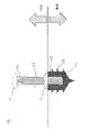
- This prefabricated utility pole includes a column 11 and an anchor 12 which is a substantially columnar object having a diameter larger than the diameter of the column 11 and has a hole 12a into which one end of the column 11 is fitted.
- the column 11 and the anchor 12 are coaxial when fitted into the hole 12a.
- the cylinder 11 can be divided into at least two parts (part 11-1 and part 11-2) in the longitudinal direction.
- the anchor 12 also has an earth auger 12b on its surface.
- the cylinder 11 can be divided into at least two parts (part 11-1 and part 11-2) in the longitudinal direction.
- the anchor 12 also has an earth auger 12b on its surface. Further, this prefabricated utility pole is provided with a locking member 13 that fills the gap between the column 11 and the hole 12a that is generated when one end of the column 11 is fitted into the hole 12a of the anchor 12. As shown in FIG.
- this assembled utility pole is composed of four structures. Since a general utility pole is a single columnar structure, its structure is significantly different from that of the assembled utility pole. Each structure is described.
- the anchor 12 is a structure buried in the ground.
- the anchor 12 has a plurality of blades (earth augers) 12b on its surface.
- FIG. 6 is a diagram explaining the function of the anchor 12. As shown in FIG. The anchor 12 excavates the soil of the ground by the earth auger 12b by rotating, and the whole anchor 12 sinks into the ground. That is, this anchor 12 can be buried in the ground.
- FIG. 7 is a view when the portion 11-2, which is the lower part of the cylinder 11, is inserted into the anchor 12 buried in the ground.
- FIG. 8 is a two-sided view for explaining the lock member 13.
- FIG. (A) is a top view
- (B) is a side view.
- the lock member 13 has a hole 13a through which the portion 11-2 is passed.
- the hole 13a has a diameter corresponding to the type (diameter) of the utility pole.
- the locking member 13 also has a spacer 13b that fills the gap between the portion 11-2 and the hole 12a of the anchor 12. As shown in FIG.
- the spacer 13b has a size corresponding to the type (diameter) of the utility pole.
- a protrusion 11a is provided at the other end (opposite to the anchor side) of the portion 11-2.
- a concave portion 11b that fits with the convex portion 11a is provided at one end (anchor side) of the portion 11-1.
- the portion 11-2 and the portion 11-1 are connected by fitting the convex portion 11a and the concave portion 11b.
- the anchor 12 has a structure that is larger in diameter and wider in the lateral direction than the conventional buried part of the utility pole. Therefore, since the ground bearing capacity is high, there is an advantage that the distance (depth) to dig a hole is shorter than before. In other words, the depth of digging is reduced. Since the distance to be excavated is reduced even when inspecting visually, this prefabricated utility pole can shorten the work time for the confirmation process of buried objects.
- Solution of issue 2 Concrete and steel are the main materials used for utility poles. Since the main cause of deterioration is corrosion due to reaction with moisture and oxygen, most of the parts where deterioration occurs are the ground, which is the boundary between the ground and the ground of the utility pole. However, with a conventional utility pole, if deterioration occurs in the utility pole, the entire utility pole must be replaced.
- FIG. 9 is a diagram for explaining the rebuilding method of this prefabricated utility pole.
- This rebuilding method is step S01 of dividing the cylinder 11; step S02 of lifting the upper part 11-1 of the divided cylinder 11; step S03 of removing the lower part 11-2 of the divided column 11 from the anchor 12; Step S04 of fitting one end of the lower part 11-2a of the new cylinder into the hole 12a of the anchor 12, and Step S05 of connecting one end of the upper part 11-1 of the hanging cylinder to the other end of the lower part 11-2a of the new cylinder. I do.
- FIG. 10 is a diagram for explaining the rebuilding method of this prefabricated utility pole.
- This rebuilding method is step S01 of dividing the cylinder 11; step S02 of lifting the upper part 11-1 of the divided cylinder 11; step S03 of removing the lower part 11-2 of the divided column 11 from the anchor 12; Step S04 of fitting one end of the lower part 11-2a of the new cylinder into the hole 12a of the anchor 12, and Step S05 of
- the utility pole is replaced entirely.
- the work of handling electric poles and the work of handling cables are generally not carried out by the same work team because the heavy machinery used and the skills of workers required are different. Therefore, it takes at least 3 days to install the utility poles (pole work team: 1 day), relocate the cables (cable work team: 1 day), and remove the poles to be rebuilt (pole work team: 1 day). necessary.
- the landowner requests reconstruction at the original location, after the above process is completed, it will be necessary to rebuild the utility poles in the original position, relocate the cables, and remove the utility poles. Double the number of days required.
- the anchor 12 and the lower part 11-2 of the utility pole also have a fitting structure. Therefore, while the upper part 11-1 of the utility pole is being lifted, the lower part 11-2 of the utility pole can be replaced with a new lower part 11-2a of the utility pole without excavation work. After the lower part 11-2 of the utility pole and the lock member 13 have been replaced, the upper part 11-1 of the utility pole being lifted is fitted into the lower part 11-2a of the new utility pole, thereby completing the reconstruction work.
- FIG. 10 is a diagram for explaining the erection method of this prefabricated utility pole.
- the main erection method is Step S11 of burying a substantially cylindrical anchor 12 having a diameter larger than the diameter of the cylindrical column 11 in the ground so that one end of the bottom surface of the substantially cylindrical body substantially coincides with the ground surface; Step S12 of fitting one end of the column 11 (lower part 11-2 of the utility pole) into the hole 12a of the anchor to be Step S13 of stacking another cylinder 11 (upper part 11-1 of the utility pole) divided at the other end of the cylinder 11 (lower part 11-2 of the utility pole) have
- this method of erecting a pole is characterized by rotating the anchor 12 in the axial direction and digging the ground with an earth auger installed on the surface of the anchor 12 .
- the telephone poles are about 8.0 to 18 meters long, and are erected with heavy machinery and human hands.
- a hole is dug by hand up to about 1.5 m, and a hole is dug after 1.5 m using heavy machinery.
- a power pole of about 8.0 to 18m will be lifted and erected in the excavated hole.
- the utility pole since the utility pole is very long, it is necessary to carefully handle it so as not to contact obstacles that exist in the work environment such as surrounding buildings, utility poles, guardrails, etc. In some cases, it is complicated to avoid obstacles. It is necessary to move to the excavation hole by a suitable route.
- the ground inside the excavated hole is not leveled, so support the utility pole with the tip of a crane, etc., and adjust the angle so that it is as vertical as possible. This work is highly difficult because it requires delicate work with a crane or the like.
- the gaps in the excavated holes are filled with earth and sand, and the holes are compacted using a compactor, etc., to complete the erection of the poles.
- the work of digging a hole is the same as the conventional one, but the anchor 12 has a structure that is laterally larger (thicker) than the buried part of the conventional utility pole, and is supported by the ground. Since the force is high, the distance (depth) to dig a hole is shorter than before. Therefore, working time can be shortened.
- the conventional method requires that about 1.5 m, which is 1/6 of the length of the utility pole, be placed underground.
- the distance (depth) for digging a hole is shortened by the anchor 12, so that the amount of manual digging work can be reduced, which is efficient.
- the anchor installation process will be carried out after excavation is completed to the target depth.
- the anchor 12 is attached to the tip of the digging and pole erecting vehicle, and is installed by embedding it with the rotation of the earth auger. At this time, the anchors 12 are pushed into the ground in such a way as to drive a screw into a tree and expand the pre-excavated hole, so that backfilling and rolling compaction are unnecessary.
- the lower part 11-2 of the utility pole is lifted by a crane or the like and a lifting process of fitting it into the anchor 12 is performed.
- the lower portion 11-2 of the utility pole is shorter than conventional utility poles. Therefore, the risk of contacting an obstacle is low, and since it is easy to handle, it can be moved to the target position by a relatively simple route.
- the pole erection work is completed simply by fitting the end of the upper part 11-1 of the utility pole into the upper end of the lower part 11-2 of the utility pole.
- this pole erection method can reduce the amount of excavation work, reduce the backfilling and rolling compaction work, improve the utility pole handling performance, and reduce the vertical adjustment work, making the work efficient.
- Electric pole 11-1 Upper part of electric pole 11-2: Lower part of electric pole 12: Anchor 12a: Hole 13: Lock member 13a: Hole 13b: Spacer
Landscapes
- Engineering & Computer Science (AREA)
- Architecture (AREA)
- Structural Engineering (AREA)
- Civil Engineering (AREA)
- Life Sciences & Earth Sciences (AREA)
- General Life Sciences & Earth Sciences (AREA)
- Mining & Mineral Resources (AREA)
- Paleontology (AREA)
- General Engineering & Computer Science (AREA)
- Foundations (AREA)
- Electric Cable Installation (AREA)
Priority Applications (3)
| Application Number | Priority Date | Filing Date | Title |
|---|---|---|---|
| US18/281,438 US20240151058A1 (en) | 2021-03-16 | 2021-03-16 | Assembled utility pole, pole building method and rebuilding method |
| PCT/JP2021/010624 WO2022195723A1 (ja) | 2021-03-16 | 2021-03-16 | 組立式電柱、建柱方法及び建替方法 |
| JP2023506445A JP7695630B2 (ja) | 2021-03-16 | 2021-03-16 | 組立式電柱、建柱方法及び建替方法 |
Applications Claiming Priority (1)
| Application Number | Priority Date | Filing Date | Title |
|---|---|---|---|
| PCT/JP2021/010624 WO2022195723A1 (ja) | 2021-03-16 | 2021-03-16 | 組立式電柱、建柱方法及び建替方法 |
Publications (1)
| Publication Number | Publication Date |
|---|---|
| WO2022195723A1 true WO2022195723A1 (ja) | 2022-09-22 |
Family
ID=83320150
Family Applications (1)
| Application Number | Title | Priority Date | Filing Date |
|---|---|---|---|
| PCT/JP2021/010624 Ceased WO2022195723A1 (ja) | 2021-03-16 | 2021-03-16 | 組立式電柱、建柱方法及び建替方法 |
Country Status (3)
| Country | Link |
|---|---|
| US (1) | US20240151058A1 (https=) |
| JP (1) | JP7695630B2 (https=) |
| WO (1) | WO2022195723A1 (https=) |
Citations (6)
| Publication number | Priority date | Publication date | Assignee | Title |
|---|---|---|---|---|
| JPS5124121Y1 (https=) * | 1970-08-07 | 1976-06-21 | ||
| JPH03260224A (ja) * | 1990-03-09 | 1991-11-20 | Shikoku Sogo Kenkyusho:Kk | 電柱支持装置 |
| JP2004084267A (ja) * | 2002-08-27 | 2004-03-18 | Asahi Tec Corp | 柱状物補強装置 |
| JP2006225987A (ja) * | 2005-02-17 | 2006-08-31 | Hiroyasu Minayoshi | コンクリート製電柱の補強方法及びコンクリート製電柱 |
| JP2008101325A (ja) * | 2006-10-17 | 2008-05-01 | Tokyo Electric Power Co Inc:The | 連結コンクリート柱 |
| JP2010101161A (ja) * | 2008-10-21 | 2010-05-06 | Kurinaa Korea Co Ltd | 施設支柱固定装置 |
Family Cites Families (12)
| Publication number | Priority date | Publication date | Assignee | Title |
|---|---|---|---|---|
| JPS50142334U (https=) * | 1974-05-13 | 1975-11-22 | ||
| JPS55155875A (en) * | 1979-05-19 | 1980-12-04 | Kamisaka Tekkosho Goumei | Method of installing strut of outdoor amusement implement and outdoor physical training implement |
| WO1999024672A1 (en) | 1997-11-07 | 1999-05-20 | Kdc Systems Ltd | Support post securing system |
| DE29924118U1 (de) * | 1999-05-21 | 2001-12-20 | Krinner Klaus | Anordnung zur Befestigung eines Gegenstandes |
| US6575853B1 (en) * | 2000-03-28 | 2003-06-10 | O'neill Raymond | Portable beach basketball system |
| US7003919B2 (en) | 2003-02-11 | 2006-02-28 | Caminoverde Ii, L.L.P. | Post mount assembly |
| US7694487B1 (en) * | 2004-05-08 | 2010-04-13 | Ryan Gary L | Setting a tubular post for an electric fixture in soil |
| KR200433073Y1 (ko) * | 2006-09-27 | 2006-12-07 | 배대환 | 심신단련 시스템용 펜스지주 결속구 |
| KR20120105093A (ko) | 2011-03-15 | 2012-09-25 | 주식회사 천지콘텍 | 울타리 설치용 기초콘크리트의 울타리지주 고정구조 |
| US10633818B2 (en) * | 2017-01-11 | 2020-04-28 | Daniel S. Spiro | Universal pole foundation with instant cap |
| US10801230B2 (en) * | 2018-07-13 | 2020-10-13 | A'Lorre Scott Durrant | Post support device for releasably mounting a post member |
| US10772413B1 (en) * | 2019-02-22 | 2020-09-15 | Harvey George LLC | Recreational utility support |
-
2021
- 2021-03-16 JP JP2023506445A patent/JP7695630B2/ja active Active
- 2021-03-16 WO PCT/JP2021/010624 patent/WO2022195723A1/ja not_active Ceased
- 2021-03-16 US US18/281,438 patent/US20240151058A1/en active Pending
Patent Citations (6)
| Publication number | Priority date | Publication date | Assignee | Title |
|---|---|---|---|---|
| JPS5124121Y1 (https=) * | 1970-08-07 | 1976-06-21 | ||
| JPH03260224A (ja) * | 1990-03-09 | 1991-11-20 | Shikoku Sogo Kenkyusho:Kk | 電柱支持装置 |
| JP2004084267A (ja) * | 2002-08-27 | 2004-03-18 | Asahi Tec Corp | 柱状物補強装置 |
| JP2006225987A (ja) * | 2005-02-17 | 2006-08-31 | Hiroyasu Minayoshi | コンクリート製電柱の補強方法及びコンクリート製電柱 |
| JP2008101325A (ja) * | 2006-10-17 | 2008-05-01 | Tokyo Electric Power Co Inc:The | 連結コンクリート柱 |
| JP2010101161A (ja) * | 2008-10-21 | 2010-05-06 | Kurinaa Korea Co Ltd | 施設支柱固定装置 |
Also Published As
| Publication number | Publication date |
|---|---|
| JP7695630B2 (ja) | 2025-06-19 |
| US20240151058A1 (en) | 2024-05-09 |
| JPWO2022195723A1 (https=) | 2022-09-22 |
Similar Documents
| Publication | Publication Date | Title |
|---|---|---|
| KR102709067B1 (ko) | 다량 수분 함유 자갈 지층 중 심층 피트 국소 냉동 보강 시공 방법 | |
| GB2519270B (en) | Stepwise repeated de-stabilisation and stabilisation of highly collapsible soil by 'soil nailing technique' for construction of railway/road underpass | |
| CN214832716U (zh) | 一种市政施工软土质地带基坑支护结构 | |
| CN112854288A (zh) | 一种由地下连续墙组成的风机筒形基础及施工方法 | |
| CN104264683A (zh) | 三面环绕文保建筑凹字形超深基坑分区支护方法 | |
| CN212742610U (zh) | 一种综合管廊复合地基结构 | |
| CN111501818B (zh) | 一种软土区水泥杆基础及其施工方法 | |
| CN105672351A (zh) | 扣接式预制带肋钢筋混凝土综合管廊结构施工方法 | |
| CN106958250B (zh) | 紧邻高层建筑开挖深基坑的支护方法及其结构 | |
| WO2022195723A1 (ja) | 組立式電柱、建柱方法及び建替方法 | |
| CN105256848A (zh) | 一种协调可控的巷道内掏土纠倾方法 | |
| TW202200872A (zh) | 高壓灌注式螺旋基樁模組 | |
| CN110820764A (zh) | 一种三维刚性基坑支护结构的施工方法 | |
| CN117646437A (zh) | 边坡与基坑双排桩支护结构以及施工方法 | |
| CN111997628B (zh) | 一种隧道施工方法 | |
| CN114215068A (zh) | 一种基坑围护装置及施工方法 | |
| CN114215106A (zh) | 上部钢结构全逆作法的多桩托柱结构及施工方法 | |
| JP7673812B2 (ja) | 建柱方法 | |
| CN114396283B (zh) | 装配式顶管工作井施工方法 | |
| CN116291226B (zh) | 一种移动平台联合临时结构进行深基坑开挖的方法 | |
| TWI748533B (zh) | 高壓灌注式螺旋基樁的施工方法 | |
| CN211448028U (zh) | 一种智能电杆基座 | |
| CN110886296A (zh) | 一种可兼作挡土墙的环框支撑围护系统及其施工方法 | |
| Jardaneh et al. | Landslides in the white mountain, Nablus, Palestine in 2018 (case study) | |
| CN108867678B (zh) | 一种空铁沉井系统 |
Legal Events
| Date | Code | Title | Description |
|---|---|---|---|
| 121 | Ep: the epo has been informed by wipo that ep was designated in this application |
Ref document number: 21931475 Country of ref document: EP Kind code of ref document: A1 |
|
| WWE | Wipo information: entry into national phase |
Ref document number: 2023506445 Country of ref document: JP |
|
| WWE | Wipo information: entry into national phase |
Ref document number: 18281438 Country of ref document: US |
|
| NENP | Non-entry into the national phase |
Ref country code: DE |
|
| 122 | Ep: pct application non-entry in european phase |
Ref document number: 21931475 Country of ref document: EP Kind code of ref document: A1 |