WO2022195723A1 - 組立式電柱、建柱方法及び建替方法 - Google Patents
組立式電柱、建柱方法及び建替方法 Download PDFInfo
- Publication number
- WO2022195723A1 WO2022195723A1 PCT/JP2021/010624 JP2021010624W WO2022195723A1 WO 2022195723 A1 WO2022195723 A1 WO 2022195723A1 JP 2021010624 W JP2021010624 W JP 2021010624W WO 2022195723 A1 WO2022195723 A1 WO 2022195723A1
- Authority
- WO
- WIPO (PCT)
- Prior art keywords
- utility pole
- anchor
- cylinder
- pole
- hole
- Prior art date
Links
- 238000000034 method Methods 0.000 title claims description 66
- 238000010276 construction Methods 0.000 title abstract description 5
- 238000009412 basement excavation Methods 0.000 description 20
- 238000004891 communication Methods 0.000 description 5
- 238000010586 diagram Methods 0.000 description 5
- 230000006866 deterioration Effects 0.000 description 4
- 239000000523 sample Substances 0.000 description 4
- 125000006850 spacer group Chemical group 0.000 description 4
- 229910000831 Steel Inorganic materials 0.000 description 3
- 238000005056 compaction Methods 0.000 description 3
- 238000007796 conventional method Methods 0.000 description 3
- 238000007429 general method Methods 0.000 description 3
- 238000009434 installation Methods 0.000 description 3
- 238000011900 installation process Methods 0.000 description 3
- 238000005096 rolling process Methods 0.000 description 3
- 239000004576 sand Substances 0.000 description 3
- 239000010959 steel Substances 0.000 description 3
- 238000012790 confirmation Methods 0.000 description 2
- 230000005611 electricity Effects 0.000 description 2
- 239000007789 gas Substances 0.000 description 2
- 239000000463 material Substances 0.000 description 2
- XLYOFNOQVPJJNP-UHFFFAOYSA-N water Substances O XLYOFNOQVPJJNP-UHFFFAOYSA-N 0.000 description 2
- QVGXLLKOCUKJST-UHFFFAOYSA-N atomic oxygen Chemical compound [O] QVGXLLKOCUKJST-UHFFFAOYSA-N 0.000 description 1
- 239000004566 building material Substances 0.000 description 1
- 239000000470 constituent Substances 0.000 description 1
- 230000007797 corrosion Effects 0.000 description 1
- 238000005260 corrosion Methods 0.000 description 1
- 230000000694 effects Effects 0.000 description 1
- 239000001301 oxygen Substances 0.000 description 1
- 229910052760 oxygen Inorganic materials 0.000 description 1
- 239000002689 soil Substances 0.000 description 1
- 239000002344 surface layer Substances 0.000 description 1
- 238000012546 transfer Methods 0.000 description 1
Images


Classifications
-
- E—FIXED CONSTRUCTIONS
- E04—BUILDING
- E04H—BUILDINGS OR LIKE STRUCTURES FOR PARTICULAR PURPOSES; SWIMMING OR SPLASH BATHS OR POOLS; MASTS; FENCING; TENTS OR CANOPIES, IN GENERAL
- E04H12/00—Towers; Masts or poles; Chimney stacks; Water-towers; Methods of erecting such structures
- E04H12/22—Sockets or holders for poles or posts
- E04H12/2207—Sockets or holders for poles or posts not used
- E04H12/2215—Sockets or holders for poles or posts not used driven into the ground
-
- E—FIXED CONSTRUCTIONS
- E02—HYDRAULIC ENGINEERING; FOUNDATIONS; SOIL SHIFTING
- E02D—FOUNDATIONS; EXCAVATIONS; EMBANKMENTS; UNDERGROUND OR UNDERWATER STRUCTURES
- E02D27/00—Foundations as substructures
- E02D27/32—Foundations for special purposes
- E02D27/42—Foundations for poles, masts or chimneys
-
- E—FIXED CONSTRUCTIONS
- E02—HYDRAULIC ENGINEERING; FOUNDATIONS; SOIL SHIFTING
- E02D—FOUNDATIONS; EXCAVATIONS; EMBANKMENTS; UNDERGROUND OR UNDERWATER STRUCTURES
- E02D5/00—Bulkheads, piles, or other structural elements specially adapted to foundation engineering
- E02D5/74—Means for anchoring structural elements or bulkheads
- E02D5/80—Ground anchors
-
- E—FIXED CONSTRUCTIONS
- E04—BUILDING
- E04H—BUILDINGS OR LIKE STRUCTURES FOR PARTICULAR PURPOSES; SWIMMING OR SPLASH BATHS OR POOLS; MASTS; FENCING; TENTS OR CANOPIES, IN GENERAL
- E04H12/00—Towers; Masts or poles; Chimney stacks; Water-towers; Methods of erecting such structures
- E04H12/22—Sockets or holders for poles or posts
- E04H12/2207—Sockets or holders for poles or posts not used
- E04H12/2215—Sockets or holders for poles or posts not used driven into the ground
- E04H12/2223—Sockets or holders for poles or posts not used driven into the ground by screwing
-
- E—FIXED CONSTRUCTIONS
- E04—BUILDING
- E04H—BUILDINGS OR LIKE STRUCTURES FOR PARTICULAR PURPOSES; SWIMMING OR SPLASH BATHS OR POOLS; MASTS; FENCING; TENTS OR CANOPIES, IN GENERAL
- E04H12/00—Towers; Masts or poles; Chimney stacks; Water-towers; Methods of erecting such structures
- E04H12/34—Arrangements for erecting or lowering towers, masts, poles, chimney stacks, or the like
Definitions
- the present disclosure relates to a prefabricated utility pole, its erection method, and its reconstruction method.
- the utility pole is shown in Figure 1.
- a large number of utility poles are laid all over the country in order to wire communication cables and power cables in high places, share telephones and electricity with users, and are recognized as social infrastructure.
- Fig. 2 shows an end view of a utility pole. It can be seen that the utility pole is composed of concrete and steel wire. Utility poles are heavy because they are composed of concrete and steel wires (see, for example, Non-Patent Document 1).
- Fig. 3 shows a general method of erecting utility poles.
- Manual excavation process In order to prevent accidents that damage buried objects, manual excavation will be carried out for sections where there is a high possibility that other companies' buried objects exist. (1) Dig the surface layer a little with a shovel (dig a hole for searching). (2) Manually insert the probe into the excavation hole and check whether there is any buried object in the excavation direction (determine whether or not something comes into contact with the tip of the probe). (3) Further dig with a shovel to the range searched with the probe. (4) Repeat steps (2) and (3) above until the excavation depth reaches approximately 1.5 m.
- Excavation process with heavy machinery (5) When there is no buried object, mechanical excavation is performed with an earth auger of a digging and pole erecting vehicle from the excavation depth of the search hole of 1.5 m or more to the target depth.
- Lifting and erection process (6) Lift the utility pole with a crane and erect it in the excavated mounting hole. At this time, it is dangerous if the utility pole sways when lifted, so it is necessary to prevent the utility pole from swinging with a rope or the like.
- Vertical adjustment and backfilling process (7) Hold the utility pole with a crane and adjust it so that it is perpendicular to the ground. (8) After confirming the verticality of the utility pole, return earth and sand to the mounting hole and backfill. (9) After backfilling is completed, the ground is compacted with a roller compactor or the like.
- the general method of erecting utility poles is to first dig the ground to erect the utility poles.
- the total length of the utility pole is about 8.0m to 9.0m for installing only the communication line, and the utility pole with a length of about 14.0 to 18.0m for installing the communication line and the power line are commonly used.
- it is required to insert about 1.5m to 3.0m, which is 1/6 of the length of the utility pole, into the ground. That is, a hole of 1.5m to 3.0m is dug. Since there is a high probability that underground pipes for social infrastructure such as electricity, gas, and water exist at a depth of about 1.5m from the ground surface, excavation is carried out manually so as not to damage them. After the hole has been dug to the target depth, the utility pole is erected by lifting the utility pole with heavy equipment and people, lifting the heavy utility pole, and inserting it into the hole.
- FIG. 4 shows a general reconstruction work method.
- Excavation process (1) Excavate a mounting hole for the new utility pole in the vicinity of the utility pole to be rebuilt. The excavation process is the same as the excavation process by manpower and the excavation process by heavy machinery described in FIG. New pillar erection, vertical adjustment, backfilling process: (2) A new utility pole is erected near the utility pole to be rebuilt and the erection hole is backfilled by the same procedures as the lifting and erection process and the vertical adjustment and backfilling process in FIG. Cable relocation process: (3) Using aerial work platforms, etc., relocate existing cables to new utility poles.
- Removal process of pillars to be reconstructed (4) Excavate the ground of the utility pole to be reconstructed, lift it with a crane or the like, and remove it. At this time, it is dangerous if the utility pole sways when it is lifted, so it is necessary to prevent it from swinging with a rope or the like. (5) Fill the hole after removal with sand and backfill it. (6) After backfilling is completed, the ground is compacted by using a roller compactor or the like. (7) If the landlord requests that the utility pole be rebuilt in the same position as the pole to be rebuilt, after work (5) is completed, work (1) to (6) will be repeated to rebuild the pole in its original position. make a change.
- the general method of rebuilding utility poles involves a series of steps: first, build a new utility pole next to the utility pole to be rebuilt, transfer the cables to the newly erected utility pole, and then remove the utility pole to be rebuilt. showing. Also, depending on the land owner, there are cases where the location of the utility pole is not allowed to change when the utility pole is rebuilt. In that case, after the rebuilding to the new utility pole is completed according to the above procedure, it is necessary to repeat the procedure of rebuilding the new utility pole in the same position as the utility pole to be rebuilt, moving the cable, and removing the nearby utility pole. In other words, the utility pole replacement work also requires a large number of man-hours, and the second problem is that it is difficult to reduce the number of man-hours.
- the present invention provides an assembly type utility pole that can simplify and improve the efficiency of work at the time of new installation and replacement and shorten the work time, a method for erecting the pole, and a method for erecting the pole.
- the purpose is to provide a rebuilding method.
- a prefabricated utility pole according to the present invention is a utility pole composed of a plurality of members stacked in a height direction, wherein the lowermost member buried in the ground is provided with a mechanism for excavating the ground. I decided to prepare.
- the prefabricated utility pole according to the present invention comprises a column, and an anchor which is a substantially columnar object having a diameter larger than the diameter of the column and has a hole into which one end of the column is fitted,
- the column and the anchor are coaxial when one end of the column is fitted into the hole of the anchor.
- the method for erecting a pole includes the step of burying an anchor having a substantially cylindrical shape having a diameter larger than that of a cylinder in the ground so that one end of the bottom surface of the substantially cylindrical structure substantially coincides with the ground surface; Fitting one end of the cylinder into a hole of the anchor in which the cylinder and the anchor are coaxial.
- the anchor has a larger diameter than the utility pole body on the ground and has a high ground bearing capacity. Therefore, the hole for erecting this prefabricated utility pole in the ground can be made shallower than the hole for erecting a conventional utility pole in the ground. Since the depth of the hole is shallow, the time required for digging can be reduced, the probability of hitting the buried object can be reduced, and the work of confirming the buried object can be reduced. In addition, since this assembly type utility pole is composed of a plurality of parts, only the deteriorated parts need to be replaced, and the replacement work can be shortened. In addition, since this prefabricated utility pole is composed of a plurality of parts, each part is smaller than conventional utility poles, and the work can be simplified.
- the present invention can provide a utility pole and a pole erection method that can simplify and improve the efficiency of work at the time of new installation and replacement, and can shorten the work time.
- the anchor of the prefabricated utility pole according to the present invention is characterized by having an earth auger on its surface.
- the step of burying the anchor in the ground in the method for erecting a pole according to the present invention is characterized by rotating the anchor in the axial direction and digging the ground with an earth auger installed on the surface of the anchor. By simply rotating the earth auger, the pre-hole can be pushed out and the anchor buried in the ground. Therefore, backfilling and rolling compaction are unnecessary.
- the column of the prefabricated utility pole according to the present invention is characterized in that it can be divided into at least two parts in the longitudinal direction.
- the method for erecting a pillar according to the present invention when the pillar is divided into two or more pieces in the longitudinal direction, after the step of fitting one end of the pillar into the hole, the other end of the pillar divided into the other end of the pillar is provided. It is characterized by performing a step of stacking up the cylinders. Only part of the pole can be replaced.
- the prefabricated utility pole according to the present invention is characterized by further comprising a locking member that fills a gap between the column and the hole that is generated when one end of the column is fitted into the hole of the anchor.
- a rebuilding method for a knockdown utility pole includes: a cylinder that can be divided into two or more in the longitudinal direction; an anchor that is a substantially cylindrical object having a diameter larger than the diameter of the cylinder, and is buried in the ground so that one end of the bottom surface of the substantially cylindrical object substantially coincides with the ground surface;
- a rebuilding method for a prefabricated utility pole in which one end of the column is fitted into a hole in the anchor that is coaxial with the column and the anchor, dividing the cylinder; lifting the upper part of the divided cylinder; removing the lower part of the divided cylinder from the anchor; Fitting one end of the lower part of a new cylinder into the hole of the anchor; and connecting one end of the upper part of the cylinder suspended to the other end of the lower part of the new cylinder.
- Reconstruction work can be simplified by making it possible to replace only some of the parts of the assembled utility pole.
- the present invention can provide a utility pole and a pole erection method that can simplify and streamline the work at the time of new construction and replacement, and can shorten the work time.
- FIG. 4 is a diagram illustrating an anchor of the knockdown utility pole according to the present invention; It is a figure explaining the assembly-type utility pole which concerns on this invention.
- FIG. 4 is a view for explaining a locking member of the knockdown utility pole according to the present invention; It is a figure explaining the rebuilding method of the assembly-type utility pole which concerns on this invention. It is a figure explaining the pole erection method of the assembly-type utility pole which concerns on this invention.
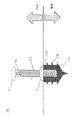
- FIG. 5 is a diagram for explaining the assembled utility pole of this embodiment.
- This prefabricated utility pole includes a column 11 and an anchor 12 which is a substantially columnar object having a diameter larger than the diameter of the column 11 and has a hole 12a into which one end of the column 11 is fitted.
- the column 11 and the anchor 12 are coaxial when fitted into the hole 12a.
- the cylinder 11 can be divided into at least two parts (part 11-1 and part 11-2) in the longitudinal direction.
- the anchor 12 also has an earth auger 12b on its surface.
- the cylinder 11 can be divided into at least two parts (part 11-1 and part 11-2) in the longitudinal direction.
- the anchor 12 also has an earth auger 12b on its surface. Further, this prefabricated utility pole is provided with a locking member 13 that fills the gap between the column 11 and the hole 12a that is generated when one end of the column 11 is fitted into the hole 12a of the anchor 12. As shown in FIG.
- this assembled utility pole is composed of four structures. Since a general utility pole is a single columnar structure, its structure is significantly different from that of the assembled utility pole. Each structure is described.
- the anchor 12 is a structure buried in the ground.
- the anchor 12 has a plurality of blades (earth augers) 12b on its surface.
- FIG. 6 is a diagram explaining the function of the anchor 12. As shown in FIG. The anchor 12 excavates the soil of the ground by the earth auger 12b by rotating, and the whole anchor 12 sinks into the ground. That is, this anchor 12 can be buried in the ground.
- FIG. 7 is a view when the portion 11-2, which is the lower part of the cylinder 11, is inserted into the anchor 12 buried in the ground.
- FIG. 8 is a two-sided view for explaining the lock member 13.
- FIG. (A) is a top view
- (B) is a side view.
- the lock member 13 has a hole 13a through which the portion 11-2 is passed.
- the hole 13a has a diameter corresponding to the type (diameter) of the utility pole.
- the locking member 13 also has a spacer 13b that fills the gap between the portion 11-2 and the hole 12a of the anchor 12. As shown in FIG.
- the spacer 13b has a size corresponding to the type (diameter) of the utility pole.
- a protrusion 11a is provided at the other end (opposite to the anchor side) of the portion 11-2.
- a concave portion 11b that fits with the convex portion 11a is provided at one end (anchor side) of the portion 11-1.
- the portion 11-2 and the portion 11-1 are connected by fitting the convex portion 11a and the concave portion 11b.
- the anchor 12 has a structure that is larger in diameter and wider in the lateral direction than the conventional buried part of the utility pole. Therefore, since the ground bearing capacity is high, there is an advantage that the distance (depth) to dig a hole is shorter than before. In other words, the depth of digging is reduced. Since the distance to be excavated is reduced even when inspecting visually, this prefabricated utility pole can shorten the work time for the confirmation process of buried objects.
- Solution of issue 2 Concrete and steel are the main materials used for utility poles. Since the main cause of deterioration is corrosion due to reaction with moisture and oxygen, most of the parts where deterioration occurs are the ground, which is the boundary between the ground and the ground of the utility pole. However, with a conventional utility pole, if deterioration occurs in the utility pole, the entire utility pole must be replaced.
- FIG. 9 is a diagram for explaining the rebuilding method of this prefabricated utility pole.
- This rebuilding method is step S01 of dividing the cylinder 11; step S02 of lifting the upper part 11-1 of the divided cylinder 11; step S03 of removing the lower part 11-2 of the divided column 11 from the anchor 12; Step S04 of fitting one end of the lower part 11-2a of the new cylinder into the hole 12a of the anchor 12, and Step S05 of connecting one end of the upper part 11-1 of the hanging cylinder to the other end of the lower part 11-2a of the new cylinder. I do.
- FIG. 10 is a diagram for explaining the rebuilding method of this prefabricated utility pole.
- This rebuilding method is step S01 of dividing the cylinder 11; step S02 of lifting the upper part 11-1 of the divided cylinder 11; step S03 of removing the lower part 11-2 of the divided column 11 from the anchor 12; Step S04 of fitting one end of the lower part 11-2a of the new cylinder into the hole 12a of the anchor 12, and Step S05 of
- the utility pole is replaced entirely.
- the work of handling electric poles and the work of handling cables are generally not carried out by the same work team because the heavy machinery used and the skills of workers required are different. Therefore, it takes at least 3 days to install the utility poles (pole work team: 1 day), relocate the cables (cable work team: 1 day), and remove the poles to be rebuilt (pole work team: 1 day). necessary.
- the landowner requests reconstruction at the original location, after the above process is completed, it will be necessary to rebuild the utility poles in the original position, relocate the cables, and remove the utility poles. Double the number of days required.
- the anchor 12 and the lower part 11-2 of the utility pole also have a fitting structure. Therefore, while the upper part 11-1 of the utility pole is being lifted, the lower part 11-2 of the utility pole can be replaced with a new lower part 11-2a of the utility pole without excavation work. After the lower part 11-2 of the utility pole and the lock member 13 have been replaced, the upper part 11-1 of the utility pole being lifted is fitted into the lower part 11-2a of the new utility pole, thereby completing the reconstruction work.
- FIG. 10 is a diagram for explaining the erection method of this prefabricated utility pole.
- the main erection method is Step S11 of burying a substantially cylindrical anchor 12 having a diameter larger than the diameter of the cylindrical column 11 in the ground so that one end of the bottom surface of the substantially cylindrical body substantially coincides with the ground surface; Step S12 of fitting one end of the column 11 (lower part 11-2 of the utility pole) into the hole 12a of the anchor to be Step S13 of stacking another cylinder 11 (upper part 11-1 of the utility pole) divided at the other end of the cylinder 11 (lower part 11-2 of the utility pole) have
- this method of erecting a pole is characterized by rotating the anchor 12 in the axial direction and digging the ground with an earth auger installed on the surface of the anchor 12 .
- the telephone poles are about 8.0 to 18 meters long, and are erected with heavy machinery and human hands.
- a hole is dug by hand up to about 1.5 m, and a hole is dug after 1.5 m using heavy machinery.
- a power pole of about 8.0 to 18m will be lifted and erected in the excavated hole.
- the utility pole since the utility pole is very long, it is necessary to carefully handle it so as not to contact obstacles that exist in the work environment such as surrounding buildings, utility poles, guardrails, etc. In some cases, it is complicated to avoid obstacles. It is necessary to move to the excavation hole by a suitable route.
- the ground inside the excavated hole is not leveled, so support the utility pole with the tip of a crane, etc., and adjust the angle so that it is as vertical as possible. This work is highly difficult because it requires delicate work with a crane or the like.
- the gaps in the excavated holes are filled with earth and sand, and the holes are compacted using a compactor, etc., to complete the erection of the poles.
- the work of digging a hole is the same as the conventional one, but the anchor 12 has a structure that is laterally larger (thicker) than the buried part of the conventional utility pole, and is supported by the ground. Since the force is high, the distance (depth) to dig a hole is shorter than before. Therefore, working time can be shortened.
- the conventional method requires that about 1.5 m, which is 1/6 of the length of the utility pole, be placed underground.
- the distance (depth) for digging a hole is shortened by the anchor 12, so that the amount of manual digging work can be reduced, which is efficient.
- the anchor installation process will be carried out after excavation is completed to the target depth.
- the anchor 12 is attached to the tip of the digging and pole erecting vehicle, and is installed by embedding it with the rotation of the earth auger. At this time, the anchors 12 are pushed into the ground in such a way as to drive a screw into a tree and expand the pre-excavated hole, so that backfilling and rolling compaction are unnecessary.
- the lower part 11-2 of the utility pole is lifted by a crane or the like and a lifting process of fitting it into the anchor 12 is performed.
- the lower portion 11-2 of the utility pole is shorter than conventional utility poles. Therefore, the risk of contacting an obstacle is low, and since it is easy to handle, it can be moved to the target position by a relatively simple route.
- the pole erection work is completed simply by fitting the end of the upper part 11-1 of the utility pole into the upper end of the lower part 11-2 of the utility pole.
- this pole erection method can reduce the amount of excavation work, reduce the backfilling and rolling compaction work, improve the utility pole handling performance, and reduce the vertical adjustment work, making the work efficient.
- Electric pole 11-1 Upper part of electric pole 11-2: Lower part of electric pole 12: Anchor 12a: Hole 13: Lock member 13a: Hole 13b: Spacer
Landscapes
- Engineering & Computer Science (AREA)
- Architecture (AREA)
- Structural Engineering (AREA)
- Civil Engineering (AREA)
- Life Sciences & Earth Sciences (AREA)
- General Life Sciences & Earth Sciences (AREA)
- Mining & Mineral Resources (AREA)
- Paleontology (AREA)
- General Engineering & Computer Science (AREA)
- Foundations (AREA)
- Electric Cable Installation (AREA)
Abstract
Description
人力による掘削工程:埋設物損傷事故を防止するために、他社埋設物が存在する可能性の高い区間については手掘りによる掘削を実施する。
(1)スコップ等で表層を少し掘る(探索用穴を掘る)。
(2)探針棒を堀穴に手で差し込み、掘削方向に埋設物がないかを確認(棒先に何かが接触するか否かで判定)する。
(3)探針棒で探索した範囲までスコップでさらに掘り進める。
(4)上述の(2)と(3)のステップを掘削深度が1.5m程度となるまで繰り返す。
重機による掘削工程:
(5)埋設物が無い場合、探索用穴の掘削深度1.5m以降から目標深度までの建込穴を穴掘建柱車のアースオーガで機械掘削する。
吊り上げ及び建て入れ工程:
(6)クレーンで電柱を吊り上げ、掘削した建込穴に建て込む。このとき、電柱を吊り上げた際に振れてしまうと危険なため、ロープ等で電柱の振れ防止を行う必要がある。
垂直調整及び埋め戻し工程:
(7)クレーンで電柱を抑え、地面に対して垂直になるように調整を行う。
(8)電柱の垂直を確認した後に、建込穴に土砂を戻し、埋め戻しを行う。
(9)埋め戻し完了後、転圧機等で地面を押し固め、転圧を行う。
地面の中には、社会インフラ設備となる電力ケーブル、水道管、ガス管などが大量に埋設されている。電柱を建てる時には、深さ1.5m~3.0mを掘るため、電力ケーブル等の埋設物に当たることがある。当たるとは埋設物を破壊することになるため、これは許容されない。広範囲にわたり、ユーザに影響が生じるためである。そこで、埋設物がないことを確認することが非常に重要である。埋設物を確認する方法は、穴を少し堀り、作業員が探針棒などを使用して確認することを繰り返しており、原始的な方法が取られている。
つまり、電柱の建柱作業には、埋設物の確認工程に多くの工数が必要であり、これを削減することが困難という第1の課題がある。
電柱は設置完了後、経年によって材料の劣化が生じる。電柱にかけられているケーブルや電柱の上に設置されているトランスなどによって発生する荷重は理想的には釣り合った状態となるが、現実には風圧等に起因する荷重は不均等に発生するため、電柱に劣化が発生した状態だと強度が低下し、折損することがある。そのため劣化が発生した電柱については新しいものに建て替える必要がある。
掘削工程:
(1)建替対象の電柱の近傍に新規電柱の建込穴の掘削を行う。当該掘削工程は、図3で説明した人力による掘削工程及び重機による掘削工程と同じである。
新柱建て入れ・垂直調整・埋め戻し工程:
(2)図3の吊り上げ及び建て入れ工程と垂直調整及び埋め戻し工程と同様の手順にて、建替対象の電柱の近傍に新たな電柱を建て込み、建込穴の埋め戻しを行う。
ケーブル移設工程:
(3)高所作業車等を使用し、新電柱へ既設のケーブル類の移設を行う。
建替対象柱の撤去工程:
(4)建替対象の電柱の地際を掘削し、クレーン等で吊り上げて撤去を行う。このとき、電柱を吊り上げた際に振れてしまうと危険なため、ロープ等で振れ防止を行う必要がある。
(5)撤去後の穴に土砂を入れて、埋め戻しを行う。
(6)埋め戻し完了後、転圧機等で地面を押し固め、転圧を行う。
(7)地主などから建替対象電柱と同じ位置への建替を要望された場合、作業(5)完了後、再度作業(1)~(6)の工程を再度行い、元位置への建替を行う。
つまり、電柱の置換作業にも、多くの工数が必要であり、これを削減することが困難という第2の課題がある。
上述した電柱の建柱作業や置換作業には工数だけでなく、多くの作業員も必要である。必要な作業員を確保できなければ、上述したような建柱作業や置換作業を行うことが困難である。つまり、少ない作業員で電柱の建柱作業や置換作業を行うことが困難という第3の課題がある。
前記円柱の一端を前記アンカーの前記穴に嵌め込んだときに前記円柱と前記アンカーとが同軸となることを特徴とする。
前記円柱と前記アンカーとを同軸とする前記アンカーの穴に前記円柱の一端を嵌める工程、を有する。
また、本組立式電柱は、複数のパーツからなるので、劣化した部分のみを交換すればよく、置換作業も短縮することができる。
さらに、本組立式電柱は、複数のパーツからなるので、一つ一つのパーツが従来の電柱より小さく、作業を簡素化することができる。
本発明に係る建柱方法の前記アンカーを地面に埋める工程では、前記アンカーを軸方向に回転させ、前記アンカーの表面に設置されたアースオーガで地面を掘り進めることを特徴とする。
アースオーガを回転させるだけで事前穴を押し広げることができ、アンカーが地中に埋まっていく。このため、埋め戻しや転圧が不要である。
本発明に係る建柱方法は、前記円柱が長手方向に2つ以上に分割されているとき、前記穴に前記円柱の一端を嵌める工程の後に、前記円柱の他端に分割されている他の円柱を積み上げる工程を行うことを特徴とする。
電柱の一部分だけを交換することができる。
スペーサの種類を選択することにより、さまざまな直径の電柱(円柱)を建てることができる。
長手方向に2つ以上に分割可能な円柱と、
前記円柱の直径より大きい直径を持つ略円柱状物であり、前記略円柱状物の底面の一端が地表に略一致するように地面に埋められたアンカーと、を備え、
前記円柱と前記アンカーとを同軸とする前記アンカーの穴に前記円柱の一端が嵌められた組立式電柱の建替方法であって、
前記円柱を分割する工程、
分割した前記円柱の上部を吊り上げる工程、
分割した前記円柱の下部を前記アンカーから外す工程、
前記アンカーの前記穴に新たな円柱の下部の一端を嵌める工程、及び
前記新たな円柱の下部の他端に吊り上げている前記円柱の上部の一端を接続する工程
を行う。
組立式電柱のパーツの一部のみを置換可能とすることで建替作業を簡略化できる。
上述した組立式電柱が前述した3つの課題を解決できることを説明する。
アンカー12は従来の電柱の埋設部に比べ、直径が大きく横方向に大きくなる構造である。そのため地盤支持力が高いことから、従来よりも穴を掘る距離(深さ)が短くなるメリットがある。つまり、穴を掘る深さが少なくなる。目視で点検しながらしたとしても、掘る距離が少なくなるため、本組立式電柱は、埋設物の確認工程の作業時間を短くすることができる。
電柱の材質としてはコンクリートや鋼が主流である。劣化の主要因はいずれも水分および酸素との反応による腐食であるため、発生する部位は電柱の地中と地上の境目である地際が大部分である。しかし、従来の電柱であれば、電柱に劣化が発生した場合は電柱1本を丸ごと交換することになる。
円柱11を分割する工程S01、
分割した円柱11の上部11-1を吊り上げる工程S02、
分割した円柱11の下部11-2をアンカー12から外す工程S03、
アンカー12の穴12aに新たな円柱の下部11-2aの一端を嵌める工程S04、及び
新たな円柱の下部11-2aの他端に吊り上げている円柱の上部11-1の一端を接続する工程S05
を行う。
図9において、
「電柱上部とケーブルの吊り上げ工程」が工程S01とS02に、
「電柱下部取り替え工程」が工程S03とS04に、
「電柱下部と電柱上部との接続工程」が工程S05に相当する。
図10は本組立式電柱の建柱方法を説明する図である。本建柱方法は、
円柱11の直径より大きい直径を持つ略円柱状物のアンカー12を、前記略円柱状物の底面の一端が地表に略一致するように地面に埋める工程S11、及び
円柱11とアンカー12とを同軸とするアンカーの穴12aに円柱11(電柱の下部11-2)の一端を嵌める工程S12、
円柱11(電柱の下部11-2)の他端に分割されている他の円柱11(電柱の上部11-1)を積み上げる工程S13
を有する。
ここで、本建柱方法は、アンカー12を地面に埋める工程S11では、アンカー12を軸方向に回転させ、アンカー12の表面に設置されたアースオーガで地面を掘り進めることを特徴とする。
図10において、
「掘削(機械/人力)及びアンカー設置工程」は工程S11に、
「吊り上げ工程」及び「ロック部材の取付工程」は工程S12に、
「電柱上部の取付工程」は工程S13に相当する。
11-1:電柱の上部
11-2:電柱の下部
12:アンカー
12a:穴
13:ロック部材
13a:孔
13b:スペーサ
Claims (8)
- 円柱と、前記円柱の直径より大きい直径を持つ略円柱状物であり、前記円柱の一端が嵌る穴を有するアンカーと、を備え、
前記円柱の一端を前記アンカーの前記穴に嵌め込んだときに前記円柱と前記アンカーとが同軸となることを特徴とする組立式電柱。 - 前記アンカーは、表面にアースオーガを有することを特徴とする請求項1に記載の組立式電柱。
- 前記円柱は、長手方向に少なくとも2分割できることを特徴とする請求項1又は2に記載の組立式電柱。
- 前記円柱の一端を前記アンカーの前記穴に嵌め込んだときに生じる、前記円柱と前記穴との隙間を埋めるロック部材をさらに備えることを特徴とする請求項1から3のいずれかに記載の組立式電柱。
- 円柱の直径より大きい直径を持つ略円柱状物のアンカーを、前記略円柱状物の底面の一端が地表に略一致するように地面に埋める工程、及び
前記円柱と前記アンカーとを同軸とする前記アンカーの穴に前記円柱の一端を嵌める工程、
を有する建柱方法。 - 前記アンカーを地面に埋める工程では、前記アンカーを軸方向に回転させ、前記アンカーの表面に設置されたアースオーガで地面を掘り進めることを特徴とする請求項5に記載の建柱方法。
- 前記円柱が長手方向に2つ以上に分割されているとき、前記穴に前記円柱の一端を嵌める工程の後に、前記円柱の他端に分割されている他の円柱を積み上げる工程を行うことを特徴とする請求項5又は6に記載の建柱方法。
- 長手方向に2つ以上に分割可能な円柱と、
前記円柱の直径より大きい直径を持つ略円柱状物であり、前記略円柱状物の底面の一端が地表に略一致するように地面に埋められたアンカーと、を備え、
前記円柱と前記アンカーとを同軸とする前記アンカーの穴に前記円柱の一端が嵌められた組立式電柱の建替方法であって、
前記円柱を分割する工程、
分割した前記円柱の上部を吊り上げる工程、
分割した前記円柱の下部を前記アンカーから外す工程、
前記アンカーの前記穴に新たな円柱の下部の一端を嵌める工程、及び
前記新たな円柱の下部の他端に吊り上げている前記円柱の上部の一端を接続する工程
を行う建替方法。
Priority Applications (3)
| Application Number | Priority Date | Filing Date | Title |
|---|---|---|---|
| US18/281,438 US20240151058A1 (en) | 2021-03-16 | 2021-03-16 | Assembled utility pole, pole building method and rebuilding method |
| JP2023506445A JPWO2022195723A1 (ja) | 2021-03-16 | 2021-03-16 | |
| PCT/JP2021/010624 WO2022195723A1 (ja) | 2021-03-16 | 2021-03-16 | 組立式電柱、建柱方法及び建替方法 |
Applications Claiming Priority (1)
| Application Number | Priority Date | Filing Date | Title |
|---|---|---|---|
| PCT/JP2021/010624 WO2022195723A1 (ja) | 2021-03-16 | 2021-03-16 | 組立式電柱、建柱方法及び建替方法 |
Publications (1)
| Publication Number | Publication Date |
|---|---|
| WO2022195723A1 true WO2022195723A1 (ja) | 2022-09-22 |
Family
ID=83320150
Family Applications (1)
| Application Number | Title | Priority Date | Filing Date |
|---|---|---|---|
| PCT/JP2021/010624 WO2022195723A1 (ja) | 2021-03-16 | 2021-03-16 | 組立式電柱、建柱方法及び建替方法 |
Country Status (3)
| Country | Link |
|---|---|
| US (1) | US20240151058A1 (ja) |
| JP (1) | JPWO2022195723A1 (ja) |
| WO (1) | WO2022195723A1 (ja) |
Citations (6)
| Publication number | Priority date | Publication date | Assignee | Title |
|---|---|---|---|---|
| JPS5124121Y1 (ja) * | 1970-08-07 | 1976-06-21 | ||
| JPH03260224A (ja) * | 1990-03-09 | 1991-11-20 | Shikoku Sogo Kenkyusho:Kk | 電柱支持装置 |
| JP2004084267A (ja) * | 2002-08-27 | 2004-03-18 | Asahi Tec Corp | 柱状物補強装置 |
| JP2006225987A (ja) * | 2005-02-17 | 2006-08-31 | Hiroyasu Minayoshi | コンクリート製電柱の補強方法及びコンクリート製電柱 |
| JP2008101325A (ja) * | 2006-10-17 | 2008-05-01 | Tokyo Electric Power Co Inc:The | 連結コンクリート柱 |
| JP2010101161A (ja) * | 2008-10-21 | 2010-05-06 | Kurinaa Korea Co Ltd | 施設支柱固定装置 |
-
2021
- 2021-03-16 US US18/281,438 patent/US20240151058A1/en active Pending
- 2021-03-16 WO PCT/JP2021/010624 patent/WO2022195723A1/ja active Application Filing
- 2021-03-16 JP JP2023506445A patent/JPWO2022195723A1/ja active Pending
Patent Citations (6)
| Publication number | Priority date | Publication date | Assignee | Title |
|---|---|---|---|---|
| JPS5124121Y1 (ja) * | 1970-08-07 | 1976-06-21 | ||
| JPH03260224A (ja) * | 1990-03-09 | 1991-11-20 | Shikoku Sogo Kenkyusho:Kk | 電柱支持装置 |
| JP2004084267A (ja) * | 2002-08-27 | 2004-03-18 | Asahi Tec Corp | 柱状物補強装置 |
| JP2006225987A (ja) * | 2005-02-17 | 2006-08-31 | Hiroyasu Minayoshi | コンクリート製電柱の補強方法及びコンクリート製電柱 |
| JP2008101325A (ja) * | 2006-10-17 | 2008-05-01 | Tokyo Electric Power Co Inc:The | 連結コンクリート柱 |
| JP2010101161A (ja) * | 2008-10-21 | 2010-05-06 | Kurinaa Korea Co Ltd | 施設支柱固定装置 |
Also Published As
| Publication number | Publication date |
|---|---|
| US20240151058A1 (en) | 2024-05-09 |
| JPWO2022195723A1 (ja) | 2022-09-22 |
Similar Documents
| Publication | Publication Date | Title |
|---|---|---|
| GB2519270B (en) | Stepwise repeated de-stabilisation and stabilisation of highly collapsible soil by 'soil nailing technique' for construction of railway/road underpass | |
| CN108867692A (zh) | 城市大断面明挖隧道临近建筑物保护及隧道基坑挖掘方法 | |
| CN112854288A (zh) | 一种由地下连续墙组成的风机筒形基础及施工方法 | |
| CN110374091A (zh) | 一种矩形抗滑桩机械成孔施工方法 | |
| CN104264683A (zh) | 三面环绕文保建筑凹字形超深基坑分区支护方法 | |
| CN105672351A (zh) | 扣接式预制带肋钢筋混凝土综合管廊结构施工方法 | |
| CN112982472B (zh) | 一种适用于未见基岩地区的输电塔基础结构及施工方法 | |
| CN214832716U (zh) | 一种市政施工软土质地带基坑支护结构 | |
| CN215211134U (zh) | 一种由地下连续墙组成的风机筒形基础 | |
| CN106958250B (zh) | 紧邻高层建筑开挖深基坑的支护方法及其结构 | |
| CN112726627B (zh) | 岩溶强烈地区钻孔灌注桩结构及施工方法 | |
| WO2022195723A1 (ja) | 組立式電柱、建柱方法及び建替方法 | |
| CN117646437A (zh) | 边坡与基坑双排桩支护结构以及施工方法 | |
| KR20090120997A (ko) | 수중 구조물의 축조 공법 | |
| CN209243731U (zh) | 小平面基坑逆作快速施工装置 | |
| CN211948535U (zh) | 一种用于开发地下空间的既有建筑集中托换构造 | |
| KR100740013B1 (ko) | 오거크레인용 확장형 굴착유니트를 이용한 가공선로건주공사 시공법 | |
| CN111441794B (zh) | 一种既有隧道改建为双层隧道的暗挖施工方法及结构 | |
| CN114215106A (zh) | 上部钢结构全逆作法的多桩托柱结构及施工方法 | |
| CN111021398A (zh) | 一种用于开发地下空间的既有建筑集中托换构造及其方法 | |
| CN105256848A (zh) | 一种协调可控的巷道内掏土纠倾方法 | |
| CN204570675U (zh) | 一种新型人工挖孔桩 | |
| TWI748533B (zh) | 高壓灌注式螺旋基樁的施工方法 | |
| CN211448028U (zh) | 一种智能电杆基座 | |
| KR102709067B1 (ko) | 다량 수분 함유 자갈 지층 중 심층 피트 국소 냉동 보강 시공 방법 |
Legal Events
| Date | Code | Title | Description |
|---|---|---|---|
| 121 | Ep: the epo has been informed by wipo that ep was designated in this application |
Ref document number: 21931475 Country of ref document: EP Kind code of ref document: A1 |
|
| WWE | Wipo information: entry into national phase |
Ref document number: 2023506445 Country of ref document: JP |
|
| WWE | Wipo information: entry into national phase |
Ref document number: 18281438 Country of ref document: US |
|
| NENP | Non-entry into the national phase |
Ref country code: DE |
|
| 122 | Ep: pct application non-entry in european phase |
Ref document number: 21931475 Country of ref document: EP Kind code of ref document: A1 |