WO2022191136A1 - 薬液投与装置 - Google Patents
薬液投与装置 Download PDFInfo
- Publication number
- WO2022191136A1 WO2022191136A1 PCT/JP2022/009752 JP2022009752W WO2022191136A1 WO 2022191136 A1 WO2022191136 A1 WO 2022191136A1 JP 2022009752 W JP2022009752 W JP 2022009752W WO 2022191136 A1 WO2022191136 A1 WO 2022191136A1
- Authority
- WO
- WIPO (PCT)
- Prior art keywords
- drug
- administration device
- plunger
- plunger rod
- solution administration
- Prior art date
- Legal status (The legal status is an assumption and is not a legal conclusion. Google has not performed a legal analysis and makes no representation as to the accuracy of the status listed.)
- Ceased
Links
Images










Classifications
-
- A—HUMAN NECESSITIES
- A61—MEDICAL OR VETERINARY SCIENCE; HYGIENE
- A61M—DEVICES FOR INTRODUCING MEDIA INTO, OR ONTO, THE BODY; DEVICES FOR TRANSDUCING BODY MEDIA OR FOR TAKING MEDIA FROM THE BODY; DEVICES FOR PRODUCING OR ENDING SLEEP OR STUPOR
- A61M5/00—Devices for bringing media into the body in a subcutaneous, intra-vascular or intramuscular way; Accessories therefor, e.g. filling or cleaning devices, arm-rests
- A61M5/178—Syringes
- A61M5/20—Automatic syringes, e.g. with automatically actuated piston rod, with automatic needle injection, filling automatically
Definitions
- such a drug delivery device includes a needle protection sleeve and a piston slidably provided in a casing, and a sleeve acting on the piston when discharging a drug solution. a shaped actuating member and a first spring acting on the actuating member.
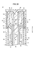
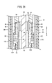
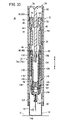
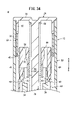
- FIG. 19 is an overall cross-sectional view showing a state where the medicinal-solution administration device of FIG. 18 starts to pierce the skin; 22 is an enlarged cross-sectional view showing the vicinity of the proximal end of the drug-solution administration device of FIG. 21; FIG. FIG. 22 is an overall cross-sectional view showing a state in which puncturing of the skin by the drug-solution administration device of FIG. 21 is completed; 24 is an enlarged cross-sectional view showing the vicinity of the proximal end of the drug-solution administration device of FIG. 23; FIG. FIG. 24 is an overall cross-sectional view showing another cross-section of the drug-solution administration device after puncturing of FIG.
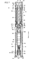
- the housing 12 is made of, for example, a resin material, and includes a cylindrical body 20 having a circular cross section and substantially constant outer diameter and inner diameter along the axial direction (directions of arrows A and B), and a base of the cylindrical body 20. It is composed of a sleeve body 22 accommodated on the end side (in the direction of arrow A) and an end cap 24 closing the proximal end of the cylindrical body 20 .
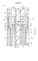
- the guide ribs 34 are, for example, provided at least three or more at equal intervals along the circumferential direction of the body main body 30, and have a substantially constant thickness along the inner periphery. They are formed in the same shape so that they linearly protrude radially inward from the surface and have the same protruding length in the radial direction from the inner peripheral surface.
- four guide ribs 34 are arranged at intervals of 90° with respect to the axial center of the main body 30, and a set of guide ribs 34 are arranged so as to face each other with the axial center of the main body 30 interposed therebetween. A case will be described.
- the rod body 84 has a circular cross-section, and a plurality of slide grooves 92 are formed on the outer peripheral surface thereof so as to be recessed radially inward and into which the guide ribs 34 of the sleeve body 22 are inserted.
- the slide grooves 92 are recessed, for example, in a rectangular cross-section with respect to the outer peripheral surface, and are provided at equal intervals in the circumferential direction corresponding to the number and arrangement of the guide ribs 34 .
- four slide grooves 92 corresponding to the guide ribs 34 will be described.
- the outer diameter D1 of the collar portion 96 of the flexible portion 86 is slightly larger than the inner diameter D2 of the main body 30 of the sleeve body 22 (D1>D2).
- a syringe holder 130 for holding the syringe 16 is formed with a pair of protrusions 142 protruding radially outward from the outer peripheral surface. 130 is held movably along the axial direction (directions of arrows A and B) inside the cover sleeve 14 together with the syringe 16 .
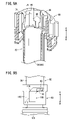
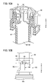
- the axial length L1 of this engaging hole 120 is formed to be greater than the axial length L2 of the outer hook 150 (L1>L2). That is, the outer hook 150 is engaged with the engagement hole 120 so as to be movable in the axial direction (directions of arrows A and B).
- the end cap 24 that constitutes the housing 12 has the shaft portion 78 that extends axially toward the distal end side (the direction of the arrow B).
- a plunger rod 82 accommodated in the interior of the plunger 12 so as to be movable in the axial direction (directions of arrows A and B) has a second rod hole 100 through which the shaft portion 78 is inserted.
- the shaft portion 78 is provided with a plurality of guide walls 78a projecting radially outward and extending in the axial direction. , and a second wall portion 79b provided in the vicinity of the tip of the shaft portion 78 with a width dimension W2 widened in the width direction with respect to the first wall portion 79a.
Landscapes
- Health & Medical Sciences (AREA)
- Vascular Medicine (AREA)
- Engineering & Computer Science (AREA)
- Anesthesiology (AREA)
- Biomedical Technology (AREA)
- Heart & Thoracic Surgery (AREA)
- Hematology (AREA)
- Life Sciences & Earth Sciences (AREA)
- Animal Behavior & Ethology (AREA)
- General Health & Medical Sciences (AREA)
- Public Health (AREA)
- Veterinary Medicine (AREA)
- Infusion, Injection, And Reservoir Apparatuses (AREA)
Priority Applications (1)
| Application Number | Priority Date | Filing Date | Title |
|---|---|---|---|
| JP2023505548A JPWO2022191136A1 (https=) | 2021-03-12 | 2022-03-07 |
Applications Claiming Priority (2)
| Application Number | Priority Date | Filing Date | Title |
|---|---|---|---|
| JP2021040764 | 2021-03-12 | ||
| JP2021-040764 | 2021-03-12 |
Publications (1)
| Publication Number | Publication Date |
|---|---|
| WO2022191136A1 true WO2022191136A1 (ja) | 2022-09-15 |
Family
ID=83226718
Family Applications (1)
| Application Number | Title | Priority Date | Filing Date |
|---|---|---|---|
| PCT/JP2022/009752 Ceased WO2022191136A1 (ja) | 2021-03-12 | 2022-03-07 | 薬液投与装置 |
Country Status (2)
| Country | Link |
|---|---|
| JP (1) | JPWO2022191136A1 (https=) |
| WO (1) | WO2022191136A1 (https=) |
Citations (3)
| Publication number | Priority date | Publication date | Assignee | Title |
|---|---|---|---|---|
| JP2017518791A (ja) * | 2014-05-07 | 2017-07-13 | アムジエン・インコーポレーテツド | 衝撃低減要素を有する自動注入器 |
| WO2019202128A1 (en) * | 2018-04-19 | 2019-10-24 | Sanofi | Force reduction in injection devices |
| JP2020524529A (ja) * | 2017-06-22 | 2020-08-20 | アムジエン・インコーポレーテツド | デバイス起動による衝突/衝撃の低減 |
-
2022
- 2022-03-07 JP JP2023505548A patent/JPWO2022191136A1/ja active Pending
- 2022-03-07 WO PCT/JP2022/009752 patent/WO2022191136A1/ja not_active Ceased
Patent Citations (3)
| Publication number | Priority date | Publication date | Assignee | Title |
|---|---|---|---|---|
| JP2017518791A (ja) * | 2014-05-07 | 2017-07-13 | アムジエン・インコーポレーテツド | 衝撃低減要素を有する自動注入器 |
| JP2020524529A (ja) * | 2017-06-22 | 2020-08-20 | アムジエン・インコーポレーテツド | デバイス起動による衝突/衝撃の低減 |
| WO2019202128A1 (en) * | 2018-04-19 | 2019-10-24 | Sanofi | Force reduction in injection devices |
Also Published As
| Publication number | Publication date |
|---|---|
| JPWO2022191136A1 (https=) | 2022-09-15 |
Similar Documents
| Publication | Publication Date | Title |
|---|---|---|
| KR102179172B1 (ko) | 자동 주사기 장치 | |
| KR102232354B1 (ko) | 감쇄기를 구비한 2 몸체 주사기 캐리어 조립체 | |
| JP3553949B2 (ja) | インプラント注入装置 | |
| TWI569842B (zh) | 藥物輸送裝置 | |
| CN102639170B (zh) | 药物输送装置 | |
| TWI612982B (zh) | 藥物輸送裝置 | |
| EP3930799B1 (en) | Auto-injector with needle cover | |
| CA3127575C (en) | Auto-injector with locking clip | |
| KR20150097784A (ko) | 약물 전달 디바이스 | |
| JP2022522174A (ja) | 可聴表示器付き自動注射器 | |
| BR112013001629B1 (pt) | montagem de seringa | |
| MX2013000880A (es) | Jeringa con doble camara con aguja retractil. | |
| JP6211790B2 (ja) | 注射器 | |
| CN114555159B (zh) | 包括针头防护件的注射装置 | |
| EP3423131B1 (en) | Automatic delivery device with end of injection indication device | |
| US20230390500A1 (en) | Medication administration device | |
| WO2022191136A1 (ja) | 薬液投与装置 | |
| US20240390601A1 (en) | Medicinal solution administration device | |
| WO2022191135A1 (ja) | 薬液投与装置 | |
| CN114423476A (zh) | 具有给药结束指示器的注射装置 | |
| JP7701974B2 (ja) | 薬液投与装置 | |
| WO2022181448A1 (en) | Medication administration device | |
| CA3127716C (en) | Auto-injector with needle cover | |
| WO2026004407A1 (ja) | 薬液投与装置 | |
| TW202525369A (zh) | 醫療免針注射系統及方法 |
Legal Events
| Date | Code | Title | Description |
|---|---|---|---|
| 121 | Ep: the epo has been informed by wipo that ep was designated in this application |
Ref document number: 22767092 Country of ref document: EP Kind code of ref document: A1 |
|
| ENP | Entry into the national phase |
Ref document number: 2023505548 Country of ref document: JP Kind code of ref document: A |
|
| NENP | Non-entry into the national phase |
Ref country code: DE |
|
| 122 | Ep: pct application non-entry in european phase |
Ref document number: 22767092 Country of ref document: EP Kind code of ref document: A1 |