WO2022190938A1 - スパイラル型膜エレメント及び膜分離システム - Google Patents
スパイラル型膜エレメント及び膜分離システム Download PDFInfo
- Publication number
- WO2022190938A1 WO2022190938A1 PCT/JP2022/008373 JP2022008373W WO2022190938A1 WO 2022190938 A1 WO2022190938 A1 WO 2022190938A1 JP 2022008373 W JP2022008373 W JP 2022008373W WO 2022190938 A1 WO2022190938 A1 WO 2022190938A1
- Authority
- WO
- WIPO (PCT)
- Prior art keywords
- spacer
- membrane element
- separation
- membrane
- separation membrane
- Prior art date
- Legal status (The legal status is an assumption and is not a legal conclusion. Google has not performed a legal analysis and makes no representation as to the accuracy of the status listed.)
- Ceased
Links
Images


Classifications
-
- B—PERFORMING OPERATIONS; TRANSPORTING
- B01—PHYSICAL OR CHEMICAL PROCESSES OR APPARATUS IN GENERAL
- B01D—SEPARATION
- B01D63/00—Apparatus in general for separation processes using semi-permeable membranes
- B01D63/10—Spiral-wound membrane modules
- B01D63/103—Details relating to membrane envelopes
-
- B—PERFORMING OPERATIONS; TRANSPORTING
- B01—PHYSICAL OR CHEMICAL PROCESSES OR APPARATUS IN GENERAL
- B01D—SEPARATION
- B01D53/00—Separation of gases or vapours; Recovering vapours of volatile solvents from gases; Chemical or biological purification of waste gases, e.g. engine exhaust gases, smoke, fumes, flue gases, aerosols
- B01D53/22—Separation of gases or vapours; Recovering vapours of volatile solvents from gases; Chemical or biological purification of waste gases, e.g. engine exhaust gases, smoke, fumes, flue gases, aerosols by diffusion
- B01D53/228—Separation of gases or vapours; Recovering vapours of volatile solvents from gases; Chemical or biological purification of waste gases, e.g. engine exhaust gases, smoke, fumes, flue gases, aerosols by diffusion characterised by specific membranes
-
- B—PERFORMING OPERATIONS; TRANSPORTING
- B01—PHYSICAL OR CHEMICAL PROCESSES OR APPARATUS IN GENERAL
- B01D—SEPARATION
- B01D61/00—Processes of separation using semi-permeable membranes, e.g. dialysis, osmosis or ultrafiltration; Apparatus, accessories or auxiliary operations specially adapted therefor
- B01D61/36—Pervaporation; Membrane distillation; Liquid permeation
- B01D61/362—Pervaporation
-
- B—PERFORMING OPERATIONS; TRANSPORTING
- B01—PHYSICAL OR CHEMICAL PROCESSES OR APPARATUS IN GENERAL
- B01D—SEPARATION
- B01D63/00—Apparatus in general for separation processes using semi-permeable membranes
- B01D63/10—Spiral-wound membrane modules
- B01D63/103—Details relating to membrane envelopes
- B01D63/1031—Glue line or sealing patterns
-
- B—PERFORMING OPERATIONS; TRANSPORTING
- B01—PHYSICAL OR CHEMICAL PROCESSES OR APPARATUS IN GENERAL
- B01D—SEPARATION
- B01D63/00—Apparatus in general for separation processes using semi-permeable membranes
- B01D63/10—Spiral-wound membrane modules
- B01D63/107—Specific properties of the central tube or the permeate channel
-
- B—PERFORMING OPERATIONS; TRANSPORTING
- B01—PHYSICAL OR CHEMICAL PROCESSES OR APPARATUS IN GENERAL
- B01D—SEPARATION
- B01D69/00—Semi-permeable membranes for separation processes or apparatus characterised by their form, structure or properties; Manufacturing processes specially adapted therefor
- B01D69/02—Semi-permeable membranes for separation processes or apparatus characterised by their form, structure or properties; Manufacturing processes specially adapted therefor characterised by their properties
-
- B—PERFORMING OPERATIONS; TRANSPORTING
- B01—PHYSICAL OR CHEMICAL PROCESSES OR APPARATUS IN GENERAL
- B01D—SEPARATION
- B01D69/00—Semi-permeable membranes for separation processes or apparatus characterised by their form, structure or properties; Manufacturing processes specially adapted therefor
- B01D69/12—Composite membranes; Ultra-thin membranes
- B01D69/1216—Three or more layers
-
- B—PERFORMING OPERATIONS; TRANSPORTING
- B01—PHYSICAL OR CHEMICAL PROCESSES OR APPARATUS IN GENERAL
- B01D—SEPARATION
- B01D71/00—Semi-permeable membranes for separation processes or apparatus characterised by the material; Manufacturing processes specially adapted therefor
- B01D71/06—Organic material
- B01D71/70—Polymers having silicon in the main chain, with or without sulfur, nitrogen, oxygen or carbon only
-
- B—PERFORMING OPERATIONS; TRANSPORTING
- B01—PHYSICAL OR CHEMICAL PROCESSES OR APPARATUS IN GENERAL
- B01D—SEPARATION
- B01D2257/00—Components to be removed
- B01D2257/50—Carbon oxides
- B01D2257/504—Carbon dioxide
-
- B—PERFORMING OPERATIONS; TRANSPORTING
- B01—PHYSICAL OR CHEMICAL PROCESSES OR APPARATUS IN GENERAL
- B01D—SEPARATION
- B01D2313/00—Details relating to membrane modules or apparatus
- B01D2313/14—Specific spacers
- B01D2313/146—Specific spacers on the permeate side
-
- B—PERFORMING OPERATIONS; TRANSPORTING
- B01—PHYSICAL OR CHEMICAL PROCESSES OR APPARATUS IN GENERAL
- B01D—SEPARATION
- B01D2315/00—Details relating to the membrane module operation
- B01D2315/10—Cross-flow filtration
-
- B—PERFORMING OPERATIONS; TRANSPORTING
- B01—PHYSICAL OR CHEMICAL PROCESSES OR APPARATUS IN GENERAL
- B01D—SEPARATION
- B01D2325/00—Details relating to properties of membranes
- B01D2325/20—Specific permeability or cut-off range
-
- B—PERFORMING OPERATIONS; TRANSPORTING
- B01—PHYSICAL OR CHEMICAL PROCESSES OR APPARATUS IN GENERAL
- B01D—SEPARATION
- B01D71/00—Semi-permeable membranes for separation processes or apparatus characterised by the material; Manufacturing processes specially adapted therefor
- B01D71/06—Organic material
- B01D71/52—Polyethers
-
- B—PERFORMING OPERATIONS; TRANSPORTING
- B01—PHYSICAL OR CHEMICAL PROCESSES OR APPARATUS IN GENERAL
- B01D—SEPARATION
- B01D71/00—Semi-permeable membranes for separation processes or apparatus characterised by the material; Manufacturing processes specially adapted therefor
- B01D71/06—Organic material
- B01D71/56—Polyamides, e.g. polyester-amides
-
- B—PERFORMING OPERATIONS; TRANSPORTING
- B01—PHYSICAL OR CHEMICAL PROCESSES OR APPARATUS IN GENERAL
- B01D—SEPARATION
- B01D71/00—Semi-permeable membranes for separation processes or apparatus characterised by the material; Manufacturing processes specially adapted therefor
- B01D71/06—Organic material
- B01D71/76—Macromolecular material not specifically provided for in a single one of groups B01D71/08 - B01D71/74
- B01D71/80—Block polymers
-
- Y—GENERAL TAGGING OF NEW TECHNOLOGICAL DEVELOPMENTS; GENERAL TAGGING OF CROSS-SECTIONAL TECHNOLOGIES SPANNING OVER SEVERAL SECTIONS OF THE IPC; TECHNICAL SUBJECTS COVERED BY FORMER USPC CROSS-REFERENCE ART COLLECTIONS [XRACs] AND DIGESTS
- Y02—TECHNOLOGIES OR APPLICATIONS FOR MITIGATION OR ADAPTATION AGAINST CLIMATE CHANGE
- Y02C—CAPTURE, STORAGE, SEQUESTRATION OR DISPOSAL OF GREENHOUSE GASES [GHG]
- Y02C20/00—Capture or disposal of greenhouse gases
- Y02C20/40—Capture or disposal of greenhouse gases of CO2
Definitions
- the present invention relates to a spiral membrane element and a membrane separation system.
- a membrane separation method has been developed as a method for separating acidic gases from mixed gases containing acidic gases such as carbon dioxide.
- the membrane separation method can efficiently separate the acid gas while suppressing the operating cost, compared to the absorption method in which the acid gas contained in the mixed gas is absorbed by an absorbent and separated.
- a spiral membrane element is used for the membrane separation method.
- a spiral-wound membrane element comprises a central tube and membrane leaves wound around the central tube.
- a membrane leaf has a separation membrane and a permeate spacer.
- a spiral wound membrane element is suitable for increasing the membrane area of the separation membrane in the membrane element.
- the spiral wound type membrane element further has, for example, a channel spacer wound around the central tube on the central tube side of the membrane leaf (for example, Patent Document 1).
- the channel spacer facilitates the delivery of permeate fluid from the membrane leaves to the central tube.
- the presence of the channel spacer when fabricating the spiral-wound membrane element facilitates winding the membrane leaves around the central tube.
- the permeation rate of the permeating fluid from the separation membrane tends to be lower than the permeation rate of the permeating fluid from the same flat membrane separation membrane.
- the permeation rate of the permeating fluid from the separation membrane tends to decrease. This tendency is particularly conspicuous in a system in which the inside of the central tube is evacuated to operate the spiral wound type membrane element (decompression system).
- an object of the present invention is to provide a spiral membrane element that is suitable for suppressing a decrease in permeation velocity (or permeation flux) of a permeation fluid through a separation membrane.
- the present inventors newly discovered that the decrease in the permeation rate of the permeating fluid in the spiral membrane element is caused by the pressure loss in the spacers, especially the channel spacers. Based on this knowledge, the inventors have further studied and completed the present invention.
- the present invention a central canal; a membrane leaf having a separation membrane and a permeate spacer wrapped around the central tube; a channel spacer connected to the permeation spacer and wound around the central tube on the central tube side of the membrane leaf; with Provided is a spiral membrane element in which the pressure loss P1 of the flow path spacer measured by the following test is smaller than the pressure loss P2 of the permeation spacer measured by the following test.
- Test A test piece is prepared by laminating a strip-shaped spacer (the channel spacer or the permeation spacer) of 150 mm long ⁇ 47 mm wide on a film made of polyethylene terephthalate.
- Nitrogen gas is sent to the space so that the pressure in the space adjacent to the film of the test piece is 0.1 MPa, and the nitrogen gas is sent to the spacer at a flow rate of 2.5 L/min. The pressure loss caused by the movement of nitrogen gas in the spacer in the longitudinal direction of the spacer is measured.
- the present invention provides the above spiral membrane element; a decompression device for decompressing the inside of the central tube; to provide a membrane separation system.
- the present invention provides a central canal; a membrane leaf having a separation membrane and a permeate spacer wrapped around the central tube; a channel spacer connected to the permeation spacer and wound around the central tube on the central tube side of the membrane leaf; with Provided is a spiral wound type membrane element in which the pressure loss P1 of the channel spacer measured by the following test is 30 kPa or less.
- Test A test piece is prepared by laminating the strip-shaped channel spacer of 150 mm long ⁇ 47 mm wide on a film made of polyethylene terephthalate.
- Nitrogen gas is sent to the space adjacent to the film of the test piece so that the pressure in the space becomes 0.1 MPa, and the nitrogen gas is sent to the flow path spacer at a flow rate of 2.5 L/min. A pressure loss caused by the movement of nitrogen gas in the longitudinal direction of the channel spacer is measured within the channel spacer.
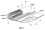
- FIG. 1 is an exploded perspective view schematically showing a spiral wound type membrane element according to an embodiment of the present invention
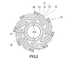
- FIG. 1 is a schematic cross-sectional view of a spiral wound membrane element
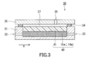
- FIG. 1 is a schematic cross-sectional view showing an example of a measuring device for measuring pressure loss of a spacer
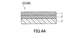
- FIG. 3 is a schematic cross-sectional view showing an example of a separation membrane included in the spiral wound type membrane element
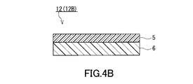
- FIG. 4 is a schematic cross-sectional view showing a modification of the separation membrane provided in the spiral wound type membrane element.
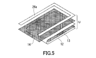
- FIG. 4 is a diagram for explaining a method for manufacturing a spiral wound type membrane element
- FIG. 4 is a diagram for explaining a method for manufacturing a spiral wound type membrane element
- 1 is a configuration diagram of a membrane separation system equipped with a spiral membrane element
- ⁇ Embodiment of Spiral Membrane Element> 1 and 2 show a spiral membrane element 10 (hereinafter referred to as "separation membrane element 10") according to one embodiment of the present invention.
- the separation membrane element 10 has a central tube 21 and a laminate 22 .
- the laminate 22 is wrapped around the central tube 21 and arranged around the central tube 21 .
- a feed fluid channel and a permeate fluid channel are formed inside the laminate 22 .
- the feed fluid is supplied from one end surface of the laminate 22 into the separation membrane element 10 and flows through the feed fluid channel parallel to the longitudinal direction of the central tube 21 .
- the feed fluid is separated to produce permeate and non-permeate fluids.
- the permeating fluid is led outside through the central tube 21 .
- the non-permeating fluid is discharged outside the separation membrane element 10 from the other end face of the laminate 22 .
- the feed fluid to be treated by the separation membrane element 10 may be gas or liquid.
- the feed fluid is a gas mixture containing acid gases, particularly a gas mixture containing carbon dioxide and nitrogen.
- the feed fluid is a mixed liquid containing volatile organic compounds, particularly a mixed liquid containing alcohol (eg isopropanol) and water.
- the separation membrane element 10 further includes a channel spacer 15.
- the flow path spacer 15 is positioned between the central tube 21 and the laminate 22 and is wound around the central tube 21 on the central tube 21 side of the laminate 22 .
- the channel spacer 15 secures a space as a permeating fluid channel between the laminate 22 and the central tube 21 .
- the separation membrane element 10 may further include a shell surrounding the laminate 22.
- the shell may be made of FRP (fiber reinforced plastic).
- end surface members may be arranged on both sides of the laminate 22 .
- the laminate 22 has multiple membrane leaves 11 .
- Each membrane leaf 11 has a separation membrane 12 and a permeate spacer 14 .
- the membrane leaf 11 has two separation membranes 12 .
- Two separation membranes 12 are superimposed on each other and sealed on three sides to have a bag-like structure.
- an adhesive layer 26 containing an adhesive is used for sealing the two separation membranes 12, for example.
- a permeation spacer 14 is arranged between the two separation membranes 12 so as to be located inside the bag-like structure.
- the open end of membrane leaf 11 is connected to channel spacer 15 , thereby connecting permeate spacer 14 to channel spacer 15 .
- the permeate spacer 14 secures a space as a permeate fluid channel between the two separation membranes 12 .
- the number of membrane leaves 11 in the laminate 22 is not particularly limited, and is, for example, 2-30.
- the laminate 22 further has supply spacers 13 .
- the feed spacer 13 is positioned outside the bag-like structure and laminated to the membrane leaf 11 .
- the stack 22 has a plurality of supply spacers 13, and in the stack 22, a plurality of supply spacers 13 and a plurality of film leaves 11 are alternately stacked.
- the supply spacer 13 secures a space as a supply fluid channel between the membrane leaves 11 .
- the central tube 21 has the role of collecting permeated fluids that have passed through each separation membrane 12 and guiding them to the outside of the separation membrane element 10 .
- the central tube 21 is provided with an opening 21h that communicates the inner space and the outer space of the central tube 21 .
- the opening 21h is, for example, a through hole formed in the wall surface of the central tube 21 .
- the center tube 21 is provided with a plurality of openings 21h at predetermined intervals along the direction in which the center tube 21 extends.
- the number of rows of the plurality of openings 21h provided along the direction in which the central tube 21 extends is not particularly limited, and is one or two, for example.
- the central tube 21 may be provided with two rows of openings 21h facing each other.
- a channel spacer 15 is in contact with each of the plurality of openings 21h. This allows the permeating fluid to flow from the channel spacer 15 into the central tube 21 through the plurality of openings 21h.
- the outer diameter of the central tube 21 is, for example, 10-100 mm, preferably 12-50 mm.
- the pressure loss P1 (kPa) of the channel spacer 15 is smaller than the pressure loss P2 (kPa) of the permeation spacer 14 .
- the pressure loss P1 can be measured by the following method using the measuring device 30 shown in FIG. First, a strip-shaped spacer 15a having a length of 150 mm and a width of 47 mm is prepared. The spacer 15a has the same shape as the channel spacer 15 before being wound around the central tube 21, except for the length and width. The longitudinal direction of the spacer 15 a coincides with the direction in which the channel spacer 15 is wound around the central tube 21 . Next, a film 41 made of polyethylene terephthalate is laminated on the spacer 15a to prepare a test piece 40. As shown in FIG. The film 41 is, for example, PET100SG2 manufactured by Panac.
- the measuring device 30 includes, for example, a holder 31, a lid member 35 and a seal member 34. As shown in FIG. Specifically, the test piece 40 is set in the holder 31 of the measuring device 30 so that the spacer 15 a of the test piece 40 is positioned below the film 41 . Openings 32 and 33 are formed in the wall surface of the holder 31 . Each of openings 32 and 33 communicates with spacer 15 a of test piece 40 . The openings 32 and 33 are positioned so that when nitrogen gas is introduced into the holder 31 through one opening 32, the nitrogen gas moves in the longitudinal direction X of the spacer 15a and is discharged from the other opening 33. is doing. The openings 32 and 33 may or may not face each other.
- the lid member 35 is fastened to the holder 31 above the holder 31 using fasteners (not shown).
- the lid member 35 is formed with an opening 36 for sending nitrogen gas to the space 37 adjacent to the film 41 of the test strip 40 .
- the sealing member 34 is positioned between the holder 31 and the lid member 35 and prevents ventilation inside and outside the measuring device 30 in portions other than the openings 32 , 33 and 36 .
- the seal member 34 is, for example, a circular cross-section seal ring (O-ring) made of an elastic material.
- FIG. 3 depicts a state in which the seal member 34, which is a seal ring, is crushed.
- nitrogen gas is sent into the space 37 through the opening 36 of the lid member 35 so that the pressure in the space 37 adjacent to the film 41 of the test piece 40 becomes 0.1 MPa, and through the opening 32 of the holder 31, 2.
- Nitrogen gas is sent to the spacer 15a at a flow rate of 5 L/min.
- the temperature of the nitrogen gas sent into the measuring device 30 is, for example, 23°C.
- Nitrogen gas sent through the opening 32 moves in the longitudinal direction X of the spacer 15 a within the spacer 15 a and is discharged from the opening 33 .
- a difference (differential pressure D1) between the pressure of the nitrogen gas sent to the opening 32 and the pressure of the nitrogen gas discharged from the opening 33 is measured.
- the differential pressure D0 is measured in the same manner as the differential pressure D1, except that the spacer 15a is not present.
- the pressure loss due to the spacer 15a is calculated based on the differential pressures D0 and D1.
- the calculated value can be regarded as the pressure loss P1 caused by the movement of the nitrogen gas in the longitudinal direction X of the spacer 15a within the spacer 15a.
- the pressure loss P2 can be measured by the same method as the pressure loss P1, except that the spacer 14a corresponding to the transmission spacer 14 is used instead of the spacer 15a.
- Spacer 14a has the same shape as transmissive spacer 14 before it is wrapped around central tube 21, except for its length and width.
- a separation membrane element 10 usually has a plurality of permeation spacers 14 .
- the pressure loss P1 of the channel spacer 15 should be smaller than the pressure loss P2 of at least one permeation spacer 14 selected from the plurality of permeation spacers 14 .
- the separation membrane element 10 may include a permeation spacer 14 exhibiting a pressure loss P2 equal to or smaller than the pressure loss P1.
- the pressure loss P1 of the channel spacer 15 has the same value as the pressure loss P2 of one permeation spacer 14 among the plurality of permeation spacers 14, and is lower than the pressure loss P2 of all the other permeation spacers 14. It can be small.
- the pressure drop P1 across the channel spacers 15 is preferably less than the pressure drop P2 across all permeate spacers 14 .
- the value (P2-P1) obtained by subtracting the pressure loss P1 from the pressure loss P2 is not particularly limited, and is, for example, 5 kPa or more, preferably 10 kPa or more, and more preferably 20 kPa or more.
- the upper limit of the value (P2-P1) is not particularly limited, and is 50 kPa, for example.
- a ratio (P1/P2) of the pressure loss P1 to the pressure loss P2 is not particularly limited, and is, for example, 0.8 or less, preferably 0.5 or less, and more preferably 0.2 or less.
- the lower limit of the ratio (P1/P2) is not particularly limited, and is 0.01, for example.
- the pressure loss P1 is, for example, 30 kPa or less, preferably 20 kPa or less, more preferably 10 kPa or less, and even more preferably 6 kPa or less.
- the lower limit of the pressure loss P1 is not particularly limited, and is 0.1 kPa, for example. Pressure loss P1 may be greater than 30 kPa in some cases.
- a central canal 21 a membrane leaf 11 having a separation membrane 12 and a permeate spacer 14 and wrapped around a central tube 21; a channel spacer 15 connected to the permeation spacer 14 and wound around the central tube 21 on the central tube 21 side of the membrane leaf 11; with A spiral wound type membrane element 10 is provided in which the pressure loss P1 of the channel spacer 15 measured by the above test is 30 kPa or less.
- the pressure loss P2 is, for example, greater than 30 kPa and less than or equal to 50 kPa.
- the pressure loss P2 may be 30 kPa or less in some cases.
- Examples of the flow path spacer 15 include nets, meshes, wire fabrics, fiber fabrics, nonwoven fabrics, grooved sheets, corrugated sheets, and the like.
- Examples of materials for the flow path spacer 15 include polypropylene (PP), polyethylene (PE), polyethylene terephthalate (PET), polyamide, polyphenylene sulfide (PPS), ethylene-chlorotrifluoroethylene copolymer (ECTFE), and epoxy resin. , resin materials such as urethane resin; natural polymers; rubber; metals, and the like.
- the thickness of the channel spacer 15 is not particularly limited, and is, for example, 300 ⁇ m or more, preferably 400 ⁇ m or more, more preferably 500 ⁇ m or more, and still more preferably 600 ⁇ m or more.
- the pressure loss P1 of the flow path spacer 15 tends to decrease as the thickness of the flow path spacer 15 increases.
- the upper limit of the thickness of the channel spacer 15 is not particularly limited, it is, for example, 2000 ⁇ m from the viewpoint of sufficiently securing the membrane area of the separation membrane 12 in the separation membrane element 10 .
- the opening ratio of the channel spacer 15 is not particularly limited, and is, for example, 30% or more, preferably 40% or more, and more preferably 50% or more.
- the pressure loss P1 of the flow path spacer 15 tends to decrease as the opening ratio of the flow path spacer 15 increases.
- the upper limit of the aperture ratio of the channel spacer 15 is not particularly limited, and is, for example, 80%.
- the aperture ratio of the channel spacer 15 can be specified by the following method. First, the channel spacer 15 is arranged on the film, and the surface of the channel spacer 15 is observed with a scanning electron microscope (SEM). From the obtained electron microscope image, the area A1 of the surface of the channel spacer 15 and the area A2 where the film can be confirmed through the channel spacer 15 (the area of the gap formed in the channel spacer 15) are calculated by image processing. do. The ratio of the area A2 to the area A1 can be specified as the aperture ratio of the flow path spacer 15 .
- SEM scanning electron microscope
- the flow path spacer 15 is preferably PE30.
- permeable spacer 14 examples include nets, meshes, wire fabrics, fiber fabrics, nonwoven fabrics, grooved sheets, corrugated sheets, and the like. Materials for the permeable spacer 14 include those mentioned above for the channel spacer 15 .
- the thickness of the transmission spacer 14 is not particularly limited, and is, for example, less than 300 ⁇ m, preferably 250 ⁇ m or less.
- the smaller the thickness of the permeate spacer 14 the easier it is to arrange a sufficient number of membrane leaves 11 within the separation membrane element 10 . In other words, a sufficient membrane area can be easily secured for the separation membrane 12 in the separation membrane element 10 .
- the lower limit of the thickness of the transmissive spacer 14 is not particularly limited, and is, for example, 100 ⁇ m.
- the thickness of the transmissive spacer 14 may be 300 ⁇ m or more in some cases.
- the opening ratio of the transmission spacers 14 is not particularly limited, and is, for example, less than 30%, preferably 25% or less, more preferably 20% or less.
- the lower limit of the aperture ratio of the transmissive spacer 14 is not particularly limited, and is, for example, 10%.
- the aperture ratio of the transmissive spacers 14 may be 30% or more in some cases.
- the aperture ratio of the permeable spacer 14 can be specified by the method described above for the channel spacer 15 .
- transmission spacer 14 is #1000E (material: PET, aperture ratio: 22%, thickness: 250 ⁇ m, pressure loss P2: 33.6 kPa).
- Transmissive spacers 14 may optionally be those illustrated in Table 1.
- the permeation spacer 14 is basically different from the channel spacer 15 .
- at least one permeation spacer 14 selected from the plurality of permeation spacers 14 may be the same as the channel spacer 15 .
- one permeation spacer 14 of the plurality of permeation spacers 14 may be the same as the channel spacer 15 and all other permeation spacers 14 may be different from the channel spacer 15 .
- one transparent spacer 14 of the plurality of transparent spacers 14 may be PE30, and all other transparent spacers 14 may be #1000E.
- the supply spacer 13 is not particularly limited, and for example, the above-described permeation spacer 14 or channel spacer 15 can be used as appropriate.
- the separation membrane 12 may be a separation membrane (gas separation membrane) that can preferentially permeate acidic gases contained in the mixed gas, and preferentially permeate volatile organic compounds contained in the mixed liquid. It may be a separation membrane (liquid separation membrane) capable of separating The separation membrane 12 as a gas separation membrane will be described below.
- a separation membrane 12A as a gas separation membrane includes, for example, a separation functional layer 1 and a porous support 3 that supports the separation functional layer 1. It may further comprise an intermediate layer 2 arranged between and. The intermediate layer 2 is in direct contact with the separation functional layer 1 and the porous support 3, for example.
- the separation functional layer 1 is, for example, a layer that preferentially allows the acidic gas contained in the mixed gas to permeate.
- the separation functional layer 1 contains a resin.
- resins contained in the separation functional layer 1 include polyether block amide resins, polyamide resins, polyether resins, polyimide resins, cellulose acetate resins, silicone resins and fluorine resins.
- the separation functional layer 1 preferably contains a polyether block amide resin.
- the separation functional layer 1 is preferably substantially made of resin.
- "consisting essentially of” means excluding other ingredients that alter the essential characteristics of the material referred to, such as 95 wt% or more, or even 99 wt% or more of the material. It means that it is composed of
- the separation functional layer 1 contains an ionic liquid.
- the separation functional layer 1 has, for example, a double network gel containing an ionic liquid.
- a double network gel is a gel that has two types of network structures that are independent of each other.
- a double network gel includes, for example, a first network structure mainly composed of an organic material, a second network structure mainly composed of an inorganic material, and an ionic liquid.
- "mainly composed of” means that 50 wt% or more, or even 70 wt% or more is composed of the material.
- the organic material for forming the first network structure includes, for example, a polymer such as polyacrylamide (especially polydialkylacrylamide such as polydimethylacrylamide).
- the polymer contained in the organic material has a structural unit derived from an acrylamide derivative and may further contain a crosslinked structure.
- a polymer containing a crosslinked structure can be produced by a known method. For example, first, a prepolymer having structural units having N-hydroxysuccinimide ester groups is prepared. A structural unit having an N-hydroxysuccinimide ester group is derived from, for example, N-acryloxysuccinimide. Next, a polymer containing a crosslinked structure can be obtained by reacting the prepolymer with an amine-based crosslinking agent.
- Amine crosslinkers are compounds with two or more primary amino groups, such as ethylene glycol bis(3-aminopropyl) ether.
- the second network structure may include a network of multiple particles.
- a network of a plurality of particles is formed, for example, by bonding a plurality of particles to each other through hydrogen bonding.
- Particles included in the second network structure may be particles exemplified as nanoparticles to be described later.
- the particles included in the second network structure are silica particles.
- specific ionic liquids include, for example, ionic liquids having imidazolium, pyridinium, ammonium, or phosphonium and substituents having 1 or more carbon atoms.
- the substituent having 1 or more carbon atoms includes an alkyl group having 1 to 20 carbon atoms, a cycloalkyl group having 3 to 14 carbon atoms, and a cycloalkyl group having 3 to 14 carbon atoms. 6 or more and 20 or less aryl groups, etc., which may be further substituted with a hydroxy group, a cyano group, an amino group, a monovalent ether group or the like (for example, a hydroxyalkyl group having 1 or more and 20 or less carbon atoms etc).
- alkyl groups having 1 to 20 carbon atoms include methyl group, ethyl group, n-propyl group, n-butyl group, n-pentyl group, n-hexyl group, n-heptyl group, n-octyl group, n- nonyl group, n-decyl group, n-undecyl group, n-dodecyl group, n-tridecyl group, n-tetradecyl group, n-pentadecyl group, n-hexadecyl group, n-heptadecyl group, n-octadecyl group, n- nonadecyl group, n-eicosadecyl group, i-propyl group, sec-butyl group, i-butyl group, 1-methylbutyl group, 1-ethylpropyl group, 2-methylbutyl
- the above alkyl group may be substituted with a cycloalkyl group.
- the number of carbon atoms in the alkyl group substituted by the cycloalkyl group is, for example, 1 or more and 20 or less.
- Alkyl groups substituted by cycloalkyl groups include cyclopropylmethyl, cyclobutylmethyl, cyclohexylmethyl, cyclohexylpropyl groups and the like, which further include hydroxy, cyano, amino, monovalent ether It may be substituted with a group or the like.
- cycloalkyl groups having 3 to 14 carbon atoms include cyclopropyl, cyclobutyl, cyclopentyl, cyclohexyl, cycloheptyl, cyclooctyl, cyclododecyl, norbornyl, bornyl and adamantyl groups. , and these may be further substituted with a hydroxy group, a cyano group, an amino group, a monovalent ether group, or the like.
- aryl group having 6 to 20 carbon atoms examples include phenyl, toluyl, xylyl, mesityl, anisyl, naphthyl, benzyl, etc. These are further hydroxy, cyano, amino, mono may be substituted with a valent ether group or the like.
- the compound having imidazolium and a substituent having 1 or more carbon atoms may further have a substituent such as an alkyl group, and may form a salt with a counter anion.
- Counter anions include alkylsulfate, tosylate, methanesulfonate, acetate, bis(fluorosulfonyl)imide, bis(trifluoromethanesulfonyl)imide, thiocyanate, dicyanamide, tricyanometanide, tetracyanoborate, hexafluorophosphate, tetrafluoro Examples include borates and halides, and bis(fluorosulfonyl)imide, bis(trifluoromethanesulfonyl)imide, dicyanamide, tricyanometanide, and tetracyanoborate are preferred from the viewpoint of gas separation performance.
- ionic liquids having imidazolium and substituents having 1 or more carbon atoms include 1-ethyl-3-methylimidazolium bis(fluorosulfonyl)imide and 1-ethyl-3-methylimidazolium dicyanamide.
- 1-ethyl-3-methylimidazolium bis(fluorosulfonyl)imide [EMI] [FSI]
- 1-ethyl-3-methylimidazolium dicyanamide [EMI] [DCA]
- 1-ethyl-3-methylimidazolium tricyanometanide [EMI] [TCM]
- 1-butyl-3-methylimidazolium bis(trifluoromethanesulfonyl)imide [C mim] [ TF 2 N]
- 1-(2-hydroxyethyl)-3-methylimidazolium bis(trifluoromethanesulfonyl)imide [C 2 OHim][TF 2 N]
- the method for producing a double network gel is not particularly limited, and for example, the method disclosed in E.Kamio et al., Adv.Mater, 29, 1704118 (2017) can be used.
- the content of the ionic liquid in the double network gel is, for example, 50 wt% or more, preferably 60 wt% or more, more preferably 70 wt% or more, and still more preferably 80 wt% or more.
- the upper limit of the content of the ionic liquid is not particularly limited, and is, for example, 95 wt%.
- the content of the first network structure mainly composed of an organic material in the double network gel is, for example, 1 wt% or more, preferably 5 wt% or more, and more preferably 10 wt% or more.
- the upper limit of the content of the first network structure is, for example, 15 wt%.
- the content of the second network structure mainly composed of an inorganic material in the double network gel is, for example, 1 wt % or more from the viewpoint of improving the strength of the double network gel.
- the upper limit of the content of the second network structure is, for example, 5 wt%.
- the ratio of the sum of the weight of the first network structure and the weight of the second network structure to the weight of the double network gel is, for example, 2 wt% or more, preferably 5 wt% or more, and more preferably 10 wt% or more. . This proportion is preferably less than or equal to 20 wt%.
- the separation functional layer 1 is preferably substantially made of double network gel.
- the thickness of the separation functional layer 1 is, for example, 50 ⁇ m or less, preferably 25 ⁇ m or less, more preferably 15 ⁇ m or less.
- the thickness of the separation functional layer 1 may be 10 ⁇ m or less, 5.0 ⁇ m or less, or 2.0 ⁇ m or less depending on the case.
- the thickness of the separation functional layer 1 may be 0.05 ⁇ m or more, or may be 0.1 ⁇ m or more.
- the intermediate layer 2 contains, for example, a resin, and may further contain nanoparticles dispersed in the resin (matrix).
- the nanoparticles may be spaced apart from each other within the matrix or may be partially aggregated.
- the material of the matrix is not particularly limited, and examples thereof include silicone resins such as polydimethylsiloxane; fluorine resins such as polytetrafluoroethylene; epoxy resins such as polyethylene oxide; polyimide resins; polyacetylene resins such as polymethylpentene; polyolefin resins such as polymethylpentene; and polyurethane resins.
- the matrix preferably contains at least one selected from the group consisting of silicone resins and polyurethane resins, and more preferably contains both silicone resins and polyurethane resins.
- the nanoparticles may contain inorganic materials or organic materials.
- Inorganic materials included in nanoparticles include, for example, silica, titania, and alumina.
- the nanoparticles preferably contain silica.
- the thickness of the intermediate layer 2 is not particularly limited, and is, for example, less than 50 ⁇ m, preferably 40 ⁇ m or less, more preferably 30 ⁇ m or less.
- the lower limit of the thickness of the intermediate layer 2 is not particularly limited, and is, for example, 1 ⁇ m.
- the intermediate layer 2 is, for example, a layer having a thickness of less than 50 ⁇ m.
- porous support 3 supports the separation functional layer 1 with the intermediate layer 2 interposed therebetween.
- Porous support 3 includes, for example, nonwoven fabric; porous polytetrafluoroethylene; aromatic polyamide fiber; porous metal; sintered metal; porous ceramic; silicone; silicone rubber; permeation containing at least one selected from the group consisting of polyvinyl fluoride, polyvinylidene fluoride, polyurethane, polypropylene, polyethylene, polystyrene, polycarbonate, polysulfone, polyetheretherketone, polyacrylonitrile, polyimide and polyphenylene oxide open-celled or closed-celled metal foams; open-celled or closed-celled polymeric foams; silica; porous glass;
- the porous support 3 may be a combination of two or more of these.
- the porous support 3 has an average pore size of, for example, 0.01-0.4 ⁇ m.
- the thickness of the porous support 3 is not particularly limited, and is, for example, 10 ⁇ m or more, preferably 20 ⁇ m or more, more preferably 50 ⁇ m or more.
- the thickness of the porous support 3 is, for example, 300 ⁇ m or less, preferably 200 ⁇ m or less, more preferably 150 ⁇ m or less.
- Separation membrane 12A can be produced, for example, by the following method. First, a coating liquid containing a material for the intermediate layer 2 is prepared. Next, a coating liquid containing the material of the intermediate layer 2 is applied onto the porous support 3 to form a coating film.
- a method for applying the coating liquid is not particularly limited, and for example, a spin coating method, a dip coating method, a gravure coating method, or the like can be used. The coating liquid may be applied using a wire bar or the like. The thickness of the intermediate layer 2 to be formed can be adjusted by adjusting the concentration of the material of the intermediate layer 2 in the coating liquid.
- the coating film is dried to form the intermediate layer 2 .
- the coating film can be dried, for example, under heating conditions.
- the heating temperature of the coating film is, for example, 50° C. or higher.
- the heating time of the coating film is, for example, 1 minute or longer, and may be 5 minutes or longer.
- the surface of the intermediate layer 2 can be subjected to an easy-adhesion treatment as necessary.
- Surface treatments such as application of a primer, corona discharge treatment, plasma treatment, etc. may be applied as the adhesion-promoting treatment.
- a coating liquid containing the material for the separation functional layer 1 is prepared.
- a coating liquid containing the material of the separation functional layer 1 is applied onto the intermediate layer 2 to obtain a coating film.
- This coating film is dried to form the separation functional layer 1 .
- the coating method and drying conditions of the coating liquid the methods and conditions described above for the intermediate layer 2 can be used. Thereby, the separation membrane 12A is obtained.
- the method for producing the separation membrane 12A is not limited to the above method.
- the separation membrane 12A can also be produced by the following method. For example, a coating liquid containing the material of the separation functional layer 1 is applied onto the transfer film to obtain a coating film. The separation functional layer 1 is formed by drying the coating film. Next, the intermediate layer 2 is formed by applying a coating liquid containing the material of the intermediate layer 2 onto the separation function layer 1 and drying it. A laminate of the intermediate layer 2 and the separation functional layer 1 is transferred to the porous support 3 . Thereby, the separation membrane 12A is obtained.
- the separation membrane 12 may be a separation membrane (liquid separation membrane) capable of preferentially permeating volatile organic compounds contained in the mixed liquid.
- the separation membrane 12 as a liquid separation membrane is, for example, a pervaporation membrane that produces a gas permeation fluid containing the above organic compound by a pervaporation method.
- the separation membrane 12 as a liquid separation membrane will be described below.
- a separation membrane 12B as a liquid separation membrane includes, for example, a separation functional layer 5 and a porous support 6 that supports the separation functional layer 5.
- Separation membrane 12B may further include a protective layer (not shown) that protects separation functional layer 5 .
- the separation functional layer 5 is in direct contact with the porous support 6, for example.
- the separation functional layer 5 is, for example, a layer that allows preferential transmission of volatile organic compounds contained in the mixed liquid.
- Separation functional layer 5 includes, for example, a silicone resin such as polydimethylsiloxane (PDMS); a hydrophobic material such as a polyolefin resin such as polypropylene.
- Separation function layer 5 preferably contains a silicone resin as a hydrophobic material.
- the separation function layer 5 may contain a hydrophobic material as a main component, or may be substantially composed only of the hydrophobic material.
- a “main component” means a component contained in the separation functional layer 5 in the largest amount by weight.
- the separation function layer 5 may contain a matrix containing a hydrophobic material and a filler dispersed in the matrix.
- the filler is embedded within the matrix. Within the matrix all fillers may be spaced from each other or may be partially agglomerated.
- the filler includes, for example, inorganic materials such as zeolite.
- the zeolite contained in the filler is preferably high silica zeolite having a high ratio of silica to alumina.
- High-silica zeolite has excellent hydrolysis resistance, and is therefore suitable for use in separating liquids containing water.
- As the high silica zeolite HSZ (registered trademark) manufactured by Tosoh Corporation, HiSiv (registered trademark) manufactured by Union Showa Corporation, USKY manufactured by Union Showa Corporation, and Zeoal (registered trademark) manufactured by Nakamura Choukou Co., Ltd. can be used. .
- the shape of the filler is, for example, particulate.
- "particulate” includes spherical, ellipsoidal, scaly and fibrous.
- the average particle size of the filler is not particularly limited, and is, for example, 50 ⁇ m or less, preferably 20 ⁇ m or less, more preferably 10 ⁇ m or less.
- the lower limit of the average particle size of the filler is, for example, 0.01 ⁇ m.
- the average particle size of the filler can be specified, for example, by the following method. First, a cross section of the separation functional layer 5 is observed with a transmission electron microscope. In the obtained electron microscope image, the area of the specific filler is calculated by image processing.
- the diameter of a circle having the same area as the calculated area is taken as the particle size (particle diameter) of that particular filler.
- the particle size of an arbitrary number (at least 50) of fillers is calculated, and the average value of the calculated values is regarded as the average particle size of the filler.
- the filler content in the separation functional layer 5 is, for example, 10 wt% or more, preferably 20 wt% or more.
- the upper limit of the filler content in the separation functional layer 5 is not particularly limited, and is, for example, 70 wt %.
- the matrix content in the separation function layer 5 is not particularly limited, and is, for example, 30 wt % to 90 wt %.
- the thickness of the separation functional layer 5 is, for example, 200 ⁇ m or less, preferably 100 ⁇ m or less, and more preferably 80 ⁇ m or less.
- the thickness of the separation functional layer 5 may be 1.0 ⁇ m or more, 10 ⁇ m or more, or 30 ⁇ m or more.
- the separation function layer 5 may have a microporous structure with an average pore size of less than 0.01 ⁇ m, or may be a dense layer with no pores on the surface.
- porous support As the porous support 6, those described above for the separation membrane 12A can be used.
- the protective layer covers, for example, the surface of the separation functional layer 5 .
- the material for the protective layer is not particularly limited, and examples thereof include silicone resins.
- the material of the protective layer may be the same as the material of the matrix of the separation functional layer 5 .
- the thickness of the protective layer is not particularly limited, and is, for example, 5 ⁇ m or more, preferably 10 ⁇ m or more, more preferably 20 ⁇ m or more.
- the thickness of the protective layer is, for example, 100 ⁇ m or less, preferably 50 ⁇ m or less.
- the separation membrane 12B can be produced by forming the separation function layer 5 on the porous support 6, for example. Specifically, first, a coating liquid containing the material of the separation functional layer 5 is prepared. The coating liquid may contain a dispersing agent for dispersing the filler in the coating liquid together with the filler. When the coating liquid contains a silicone resin, the coating liquid may further contain a catalyst for curing the silicone resin. Next, a coating film is obtained by coating the coating liquid on the porous support 6 . The separation functional layer 5 is formed by drying the coating film.
- the separation membrane 12 is folded in two such that the separation functional layer 1 of the separation membrane 12 is located inside.
- a feed spacer 13 is placed between the two folded separation membranes 12 and a permeate spacer 14 is placed above the separation membrane 12 .
- an adhesive 26a is applied to the three sides of the perimeter of the transmissive spacer 14. As shown in FIG. Thus, the separation membrane unit U is obtained.
- the adhesive 26a is in an uncured state at this point.
- the spacer 16 has, for example, a first portion 16a directly wound around the central tube 21 and a second portion 16b laminated with the separation membrane unit U.
- the first portion 16 a of the spacer 16 corresponds to the channel spacer 15 and the second portion 16 b corresponds to the permeation spacer 14 .
- the material, thickness, etc. of the first portion 16a may be the same as or different from those of the second portion 16b.
- a plurality of separation membrane units U are arranged stepwise on the second portion 16 b of the spacer 16 .
- the number of multiple separation membrane units U is not particularly limited, and is, for example, 2-30. Note that the uppermost separation membrane unit U may not have the permeation spacer 14 .
- the number of turns of the first portion 16a is not particularly limited, and is, for example, 1-15, preferably 2-10.
- a plurality of separation membrane units U are wound around the central tube 21 .
- the uppermost separation membrane unit U is stacked with the second portion 16 b of the spacer 16 .
- the adhesive 26a is cured to form the adhesive layer 26 and the bag-like membrane leaf 11 is formed. An assembly including the central tube 21 and the laminate 22 is thereby obtained.
- the spacer 16 is not limited to the shape shown in FIG.
- the spacer 16 may further have a third portion (not shown) connected to the second portion 16b and extending from the second portion 16b on the opposite side of the central tube 21 .
- the third portion is wound around the central tube 21 on the outside of the laminate 22 formed by winding the separation membrane unit U around the central tube 21 . That is, the third portion can cover the laminate 22 on the outside of the laminate 22 .
- a film for example, Lumirror 38E20 manufactured by Panac Co., Ltd.
- the material, thickness, etc. of the third portion may be the same as or different from the first portion 16a.
- membrane separation of the feed fluid by the separation membrane 12 proceeds with the difference (pressure difference) between the pressure of the feed fluid and the pressure of the permeated fluid as a driving force. Therefore, when a pressure loss occurs in the separation membrane element 10, the pressure difference is reduced, and the permeation speed and permeation flux of the fluid passing through the separation membrane 12 are lowered.
- the pressure difference is greater than in the method of pressurizing the feed fluid to operate the separation membrane element 10 (pressurization method). Since it tends to be small, the influence of the decrease in pressure difference due to pressure loss is large.
- the pressure loss tends to occur particularly significantly in the channel spacer 15 where the permeated fluid from each membrane leaf 11 concentrates.
- the pressure loss P1 of the channel spacer 15 is set smaller than the pressure loss P2 of the permeation spacer 14, thereby effectively suppressing the decrease in the pressure difference.
- the separation membrane element 10 of the present embodiment it is possible to sufficiently suppress a decrease in the permeation velocity and permeation flux of the permeating fluid through the separation membrane 12 by suppressing a decrease in the pressure difference.
- the separation membrane element 10 provided with the separation membrane 12 (specifically, the separation membrane 12A) and the flat membrane-like separation membrane 12 (specifically, the separation membrane 12A) are each separated.
- the ratio R of the carbon dioxide permeation rate T2 (GPU) from the separation membrane element 10 to the carbon dioxide permeation rate T (GPU) from the flat separation membrane 12 is, for example, 90. % or more, preferably 95% or more.
- the feed fluid supplied to the separation membrane element 10 or the flat separation membrane 12 has a temperature of 23° C.
- the pressure in the space where the permeate is obtained matches the atmospheric pressure (eg, 101 kPa) in the measurement environment.
- GPU means 10 ⁇ 6 ⁇ cm 3 (STP)/(sec ⁇ cm 2 ⁇ cmHg).
- cm 3 (STP) means the volume of carbon dioxide at 1 atmosphere and 0°C.
- the separation membrane element 10 is increased with respect to the permeation rate T1 (GPU) of carbon dioxide from the flat separation membrane 12 when the flat separation membrane 12 is operated in a reduced pressure system.
- the ratio R1 of the permeation rate T2 (GPU) of carbon dioxide from the separation membrane element 10 when operated in the pressure mode is, for example, 85% or more, preferably 90% or more, and more preferably 95% or more.
- the permeation rate T1 can be measured under the conditions described later.
- the transmission rate T2 is the same as described above for the ratio R.
- the permeation rate of carbon dioxide through the flat separation membrane 12 is T1 (GPU).
- T1 GPU
- the feed fluid supplied to the separation membrane element 10 or the flat separation membrane 12 has a temperature of 23° C. and a pressure of 0.1 MPa. be.
- a vacuum pump is used to reduce the pressure of the space in which the permeated fluid is obtained (the space within the permeated fluid flow path) to about 10 kPa or less.
- the separation membrane element 10 provided with the separation membrane 12 (specifically, the separation membrane 12B) and the flat separation membrane 12 ( Specifically, when each of the separation membranes 12B) is operated under reduced pressure, the ratio of IPA from the separation membrane element 10 to permeation flux F1 (kg/m 2 /hr) of IPA from the flat separation membrane 12 is A ratio L of the permeation flux F2 (kg/m 2 /hr) is, for example, 60% or more.
- the upper limit of the ratio L is not particularly limited, and is, for example, 90%.
- the temperature of the feed fluid supplied to the separation membrane element 10 or the flat separation membrane 12 is 40°C.
- the amount of feed fluid is appropriately set within a range that does not affect the measurement of the permeation fluxes F1 and F2.
- the supply flow rate of the feed fluid sent to the separation membrane element 10 may be set at 40 g/min.
- the concentration of IPA in the feed fluid is 5 wt%.
- a vacuum pump is used to reduce the pressure of the space in which the permeated fluid is obtained (the space within the permeated fluid channel) to 1.5 kPa.
- Vacuum systems typically result in gaseous permeate fluids. By condensing the gaseous permeate and analyzing the composition of the resulting liquid permeate, the permeate fluxes F1 and F2 can be determined.
- the separation membrane element 10 of this embodiment it is not necessary to reduce the pressure loss P2 of the permeation spacer 14 as compared with the conventional one. That is, there is no need, for example, to increase the thickness of the transmissive spacer 14 in order to reduce the pressure drop P2. Therefore, according to the separation membrane element 10 of the present embodiment, there is an advantage that the number of membrane leaves 11 in the separation membrane element 10 can be maintained, thereby securing a sufficient membrane area for the separation membrane 12 .
- a permeation spacer 14 exhibiting a smaller pressure loss P2 than conventional ones may be used.
- An example of the application of the separation membrane element 10 of the present embodiment is the application of separating acidic gas from a mixed gas containing acidic gas.
- the acid gas of the mixed gas includes carbon dioxide, hydrogen sulfide, carbonyl sulfide, sulfur oxides (SOx), hydrogen cyanide, nitrogen oxides (NOx), etc. Carbon dioxide is preferred.
- the mixed gas contains other gases than acid gas. Other gases include, for example, hydrogen, non-polar gases such as nitrogen, and inert gases such as helium, preferably nitrogen.
- the separation membrane element 10 having the separation membrane 12A described above is suitable for separating carbon dioxide from a mixed gas containing carbon dioxide and nitrogen.
- Volatile organic compounds include, for example, alcohols, typically lower alcohols.
- a lower alcohol is, for example, an alcohol having 5 or less carbon atoms.
- the lower alcohol may be a monohydric alcohol or a polyhydric alcohol.
- the lower alcohol may be linear or branched.
- Lower alcohols include, for example, methanol, ethanol, n-propanol, isopropanol (IPA), n-butanol, 2-butanol, isobutanol, t-butanol and n-pentanol, preferably IPA.
- Volatile organic compounds may be alcohols other than lower alcohols, such as phenol.
- the mixed liquid contains liquids other than volatile organic compounds.
- the other liquid is typically water.
- the separation membrane element 10 having the separation membrane 12B described above is suitable for separating alcohol from a mixed liquid containing alcohol and water.
- the separation membrane element 10 of the present embodiment is used to (i) separate carbon dioxide from a mixed gas containing carbon dioxide and nitrogen, and (ii) separate alcohol from a mixed liquid containing alcohol and water. It is preferable that at least one of is established.
- the application of the separation membrane element 10 is not limited to the application (i) or (ii) above.
- the membrane separation system 100 of this embodiment includes the separation membrane element 10 and the decompression device 60 described above.
- the pressure reducing device 60 can reduce the pressure inside the central tube 21 of the separation membrane element 10 .
- the decompression device 60 can generate or increase the differential pressure between the space in the feed fluid channel and the space in the permeate fluid channel of the separation membrane element 10 .
- a specific example of the decompression device 60 is a vacuum device such as a vacuum pump.
- the membrane separation system 100 may comprise two separation membrane elements 10a and 10b and two pressure reducing devices 60a and 60b.
- the membrane separation system 100 is suitable for separating acid gases from gas mixtures containing acid gases.
- the membrane separation system 100 further includes a mixed fluid supply path 50.
- the mixed fluid supply path 50 is connected to the mixed fluid inlet of the separation membrane element 10a, and is a path for supplying the mixed fluid from a tank (not shown) storing the mixed fluid to the separation membrane element 10a.
- the mixed fluid supply path 50 may or may not be provided with a pressurizing device 64 for pressurizing the space in the supply fluid path of the separation membrane element 10a.
- Pressurization devices 64 include, for example, compressors, blowers, and back pressure valves. The pressurizing device 64 can pressurize the space in the feed fluid path of the separation membrane element 10a, for example, by pressurizing the mixed fluid supplied to the separation membrane element 10a.
- the membrane separation system 100 further comprises a permeate fluid supply channel 52 .
- the permeate fluid supply path 52 is connected to the permeate fluid outlet of the separation membrane element 10a and the permeate fluid inlet of the separation membrane element 10b, and supplies the permeate fluid from the separation membrane element 10a to the separation membrane element 10b from the separation membrane element 10a. It is a route for The permeated fluid from the separation membrane element 10a is further processed in the separation membrane element 10b.
- a decompression device 60 a is arranged in the permeate fluid supply path 52 .
- the permeate fluid supply path 52 has a first portion 52a extending from the separation membrane element 10a to the pressure reducing device 60a and a second portion 52b extending from the pressure reducing device 60a to the separation membrane element 10b.
- the decompression device 60a can decompress the space in the permeate fluid path of the separation membrane element 10a through the first portion 52a.
- the decompression device 60a for example, sucks the permeated fluid that has passed through the first portion 52a and discharges the permeated fluid to the second portion 52b.
- a pressure device (not shown) for pressurizing the permeated fluid discharged from the decompression device 60a may or may not be disposed in the second portion 52b. According to this pressurizing device, the space in the supply fluid path of the separation membrane element 10b can be pressurized.
- Pressurization devices include, for example, compressors, blowers and back pressure valves.
- the membrane separation system 100 further includes a first discharge path 54.
- the first discharge path 54 is connected to the non-permeate fluid outlet of the separation membrane element 10a, and is a path for discharging the non-permeate fluid from the separation membrane element 10a.
- the first discharge path 54 is formed with an opening (discharge port 72 ) for discharging non-permeating fluid from the first discharge path 54 .
- the membrane separation system 100 may further comprise a tank (not shown) for storing the non-permeate fluid, and the first discharge line 54 may be connected to the tank.
- the membrane separation system 100 further comprises a second discharge path 56 and a tank 70.
- the second discharge path 56 is connected to the permeated fluid outlet of the separation membrane element 10b and the inlet of the tank 70, and is a path for sending the permeated fluid from the separation membrane element 10b to the tank 70.
- the tank 70 can store the permeated fluid sent from the separation membrane element 10b.
- a decompression device 60 b is arranged in the second discharge path 56 .
- the second discharge path 56 has a first portion 56a extending from the separation membrane element 10b to the pressure reducing device 60b and a second portion 56b extending from the pressure reducing device 60b to the tank 70.
- the decompression device 60 can decompress the space in the permeate fluid path of the separation membrane element 10b through the first portion 56a.
- the decompression device 60b for example, sucks the permeated fluid that has passed through the first portion 56a and discharges the permeated fluid to the second portion 56b.
- the membrane separation system 100 further includes a third discharge path 58.
- the third discharge path 58 is connected to the non-permeate fluid outlet of the separation membrane element 10b and is a path for discharging the non-permeate fluid from the separation membrane element 10b.
- the third discharge path 58 may join the mixed fluid supply path 50 .
- the third discharge path 58 is connected to the pressurizing device 64 and joins the mixed fluid supply path 50 at the pressurizing device 64 . Since the third discharge path 58 joins the mixed fluid supply path 50, it is possible to reuse, for example, the non-permeating fluid containing the acid gas that has not been completely separated by the separation membrane element 10b.
- Each of the routes of the membrane separation system 100 is composed of, for example, metal or resin piping.
- the separation operation can be performed by decompressing the space in the permeate fluid path of the separation membrane element 10 by the decompression device 60 . Separation operation by such a depressurization method is suitable for reducing the energy required to separate the mixed fluid compared to the pressurization method.
- Example 1 [Preparation of Separation Membrane] First, a coating solution containing silicone resin and polyurethane resin at a weight ratio of 9:1 was prepared. The coating liquid contained water as a solvent. Next, a coating film was obtained by applying the coating liquid onto the porous support by a gravure coating method. As the porous support, a UF membrane (ultrafiltration membrane) RS-50 (a laminate of a PVDF porous layer and a PET nonwoven fabric) manufactured by Nitto Denko was used. An intermediate layer was formed by drying the obtained coating film. Thus, a laminate of the porous support and the intermediate layer was produced.
- UF membrane ultrafiltration membrane
- RS-50 a laminate of a PVDF porous layer and a PET nonwoven fabric
- polyether block amide (Pebax MH1657 manufactured by Arkema) was added to 98 g of a 70 wt% isopropanol aqueous solution and stirred at 80°C for 3 hours to prepare a 2 wt% Pebax solution.
- the prepared solution was applied onto the intermediate layer by gravure coating.
- the separated functional layer was formed by drying the obtained coating film. Thus, a separation membrane was obtained.
- PE30 manufactured by NBC Meshtec Co., Ltd. was used as the spacer 16 in FIG.
- a spiral wound membrane element of Example 1 was produced by the method described with reference to .
- the first portion 16a of the spacer 16 had a length of 90 mm in the direction in which it was wound around the central tube, and a length of 280 mm in the direction in which the central tube extends.
- the permeable spacer 14 had a length of 290 mm in the direction in which it was wrapped around the central tube, and a length of 280 mm in the direction in which the central tube extended. Spacers 16 and permeate spacers 14 were wrapped around the central tube and then cut at the ends.
- the effective length of these spacers in the extending direction of the central tube was 180 mm.
- the outer diameter of the central tube 21 was 17.3 mm, and the outer diameter of the spiral wound membrane element was about 2 inches.
- Example 2 Spiral membrane elements of Examples 2 and 3 were produced in the same manner as in Example 1, except that the spacer 16 was changed as shown in Table 2.
- Example 4 The spiral membrane element of Example 4 was prepared in the same manner as in Example 1, except that the laminate of the porous support and the intermediate layer (the laminate before producing the separation functional layer) was used as the separation membrane. made.
- Example 5 changing the length of the first portion 16a of the spacer 16 and the permeable spacer 14 to 1 m in the direction in which the central tube extends; changing the length of the permeable spacer 14 in the direction in which it is wound around the central tube to 400 mm; Same as Example 1 except that the length of the first portion 16a of the spacer 16 in the winding direction was changed to 136 mm and the outer diameter of the spiral membrane element was changed to about 4 inches.
- a spiral wound membrane element of Example 5 was produced by the method.
- Comparative example 1 A spiral membrane element of Comparative Example 1 was produced in the same manner as in Example 1, except that #1000E manufactured by KB Seiren Co., Ltd. was used as the spacer 16 .
- Comparative example 2 A spiral membrane element of Comparative Example 2 was produced in the same manner as in Example 4, except that #1000E manufactured by KB Seiren Co., Ltd. was used as the spacer 16 .
- the feed fluid injected into the metal cell had a temperature of 23° C. and a pressure of 0.1 MPa.
- the pressure in the space adjacent to the main surface of the separation membrane on the porous support side was reduced to about 10 kPa or less.
- the permeation rate T1 of carbon dioxide was calculated based on the obtained composition of the permeated fluid, the weight of the permeated fluid, and the like.
- the composition of the permeating fluid was measured using gas chromatography (G2700T manufactured by Yanaco Technical Science).
- the permeation rate T1 of the separation membrane used in Example 1 was 100 GPU.
- the permeation rate T1 of the separation membrane (laminate of porous support and intermediate layer) used in Example 4 was 1500 GPU.
- the permeation rate T2 was measured by the following method. First, a feed fluid (carbon dioxide) was supplied to the feed fluid channel of the spiral membrane element. The feed fluid had a temperature of 23° C. and a pressure of 0.2 MPa. As a result, a permeated fluid was obtained through the central tube of the spiral membrane element. The carbon dioxide permeation rate T2 was calculated based on the obtained flow rate of the permeated fluid. The flow rate of the permeated fluid was measured using a soap film flowmeter (manufactured by HORIBA).
- the permeation rate T3 was determined by changing the pressure of the feed fluid (carbon dioxide) supplied to the feed fluid channel to 0.1 MPa, and by using a vacuum pump to reduce the pressure in the central tube of the spiral membrane element to about 10 kPa or less. It was measured by the same method as the permeation rate T2, except that
- the ratios R1 and R2 are lower than those of Comparative Examples 1 and 2, respectively.
- the ratios R1 were all 83% or more, which was higher than the ratios R1 of Comparative Examples 1 and 2.
- the ratio R2 was 78% or more, which was higher than the ratio R2 of Comparative Examples 1 and 2. From this result, it can be seen that the spiral wound type membrane element of the present embodiment is suitable for suppressing a decrease in the permeation rate of the permeating fluid through the separation membrane.
- Example 6 [Preparation of Separation Membrane] First, silicone resin (YSR3022 manufactured by Momentive Performance Materials Japan), silicone curing catalyst (YC6831 manufactured by Momentive Performance Materials Japan), and high silica zeolite (HiSiv3000 manufactured by Union Showa) A coating liquid was prepared by mixing. Next, a coating film was obtained by applying the coating solution onto a porous support (RS-50 manufactured by Nitto Denko Corporation). A separation functional layer was produced by drying the coating film. Thus, a separation membrane was obtained. In the separation functional layer, the weight ratio of silicone resin and high silica zeolite was 50:50.
- PE30 manufactured by NBC Meshtec Co., Ltd. was used as the spacer 16 in FIG.
- a spiral wound membrane element of Example 6 was produced by the method described with reference to .
- the first portion 16a of the spacer 16 had a length of 90 mm in the direction in which it was wound around the central tube, and a length of 280 mm in the direction in which the central tube extends.
- the transmission spacer 14 had a length of 140 mm in the direction in which it was wrapped around the central tube, and a length of 280 mm in the direction in which the central tube extended. Spacers 16 and permeate spacers 14 were wrapped around the central tube and then cut at the ends.
- the effective length of these spacers in the extending direction of the central tube was 180 mm.
- the outer diameter of the central tube 21 was 17.3 mm, and the outer diameter of the spiral wound membrane element was about 2 inches.
- Example 7 A spiral membrane element of Example 7 was produced in the same manner as in Example 6, except that the spacer 16 was changed as shown in Table 3.
- Comparative Example 3 A spiral membrane element of Comparative Example 3 was produced in the same manner as in Example 6, except that #1000E manufactured by KB Seiren Co., Ltd. was used as the spacer 16 .
- the permeation flux F1 (kg/m 2 /hr) of isopropanol (IPA) in the flat membrane state was measured.
- the permeation flux F1 was measured by the following method. First, the separation membrane was set in a metal cell in the state of a flat membrane and sealed with an O-ring to prevent leakage. The membrane area of the separation membrane was 34.2 cm 2 . Next, the metal cell was filled with the supply fluid so that the supply fluid was in contact with the main surface of the separation membrane on the side of the separation functional layer.
- the feed fluid consisted essentially of IPA and water.
- the concentration of IPA in the feed fluid was 5 wt%.
- the feed fluid fed into the metal cell had a temperature of 40°C.
- the pressure in the space adjacent to the main surface of the separation membrane on the porous support side was reduced to 1.5 kPa.
- a gas permeating fluid was obtained from the main surface of the separation membrane on the porous support side. That is, separation by the pervaporation method (PV) progressed due to the reduced pressure operation.
- the permeate was liquefied by cooling the gaseous permeate with liquid nitrogen at -196°C. Gas chromatography was used to analyze the composition of the liquid permeate.
- the permeation flux F1 of IPA was calculated based on the obtained composition of the permeated fluid, the weight of the permeated fluid, and the like.
- the permeation flux F2 was measured by the following method. First, a feed fluid was supplied to the feed fluid channel of the spiral membrane element.
- the feed fluid consisted essentially of IPA and water.
- the concentration of IPA in the feed fluid was 5 wt%.
- the feed fluid had a temperature of 40°C.
- the feed flow rate of the feed fluid was 40 g/min.
- the pressure inside the central tube of the spiral membrane element was reduced to 1.5 kPa using a vacuum pump. As a result, a gas permeate fluid was obtained through the central tube of the spiral wound type membrane element. That is, separation by the pervaporation method (PV) progressed due to the reduced pressure operation.
- PV pervaporation method
- the permeate was liquefied by cooling the gaseous permeate with liquid nitrogen at -196°C. Gas chromatography was used to analyze the composition of the liquid permeate.
- the permeation flux F2 of IPA was calculated based on the obtained composition of the permeated fluid, the weight of the permeated fluid, and the like.
- the ratio L was higher than that of Comparative Example 3.
- the ratio L was about 63%, which was higher than the ratio L of Comparative Example 3.
- the spiral wound type membrane element of this embodiment is suitable for separating acid gas from a mixed gas containing acid gas.
- the spiral wound membrane element of the present embodiment is suitable for separating carbon dioxide from off-gases of chemical plants or thermal power plants.
- the spiral wound type membrane element of this embodiment is also suitable for separating organic compounds from a mixed liquid containing volatile organic compounds.
Landscapes
- Chemical & Material Sciences (AREA)
- Chemical Kinetics & Catalysis (AREA)
- Engineering & Computer Science (AREA)
- Water Supply & Treatment (AREA)
- Analytical Chemistry (AREA)
- General Chemical & Material Sciences (AREA)
- Oil, Petroleum & Natural Gas (AREA)
- Separation Using Semi-Permeable Membranes (AREA)
Priority Applications (3)
| Application Number | Priority Date | Filing Date | Title |
|---|---|---|---|
| US18/281,116 US12576365B2 (en) | 2021-03-09 | 2022-02-28 | Spiral membrane element and membrane separation system |
| EP22766897.7A EP4306205A4 (en) | 2021-03-09 | 2022-02-28 | Spiral membrane element and membrane separation system |
| JP2023505308A JP7857910B2 (ja) | 2021-03-09 | 2022-02-28 | スパイラル型膜エレメント及び膜分離システム |
Applications Claiming Priority (2)
| Application Number | Priority Date | Filing Date | Title |
|---|---|---|---|
| JP2021-037655 | 2021-03-09 | ||
| JP2021037655 | 2021-03-09 |
Publications (1)
| Publication Number | Publication Date |
|---|---|
| WO2022190938A1 true WO2022190938A1 (ja) | 2022-09-15 |
Family
ID=83226618
Family Applications (1)
| Application Number | Title | Priority Date | Filing Date |
|---|---|---|---|
| PCT/JP2022/008373 Ceased WO2022190938A1 (ja) | 2021-03-09 | 2022-02-28 | スパイラル型膜エレメント及び膜分離システム |
Country Status (4)
| Country | Link |
|---|---|
| US (1) | US12576365B2 (cg-RX-API-DMAC7.html) |
| EP (1) | EP4306205A4 (cg-RX-API-DMAC7.html) |
| JP (1) | JP7857910B2 (cg-RX-API-DMAC7.html) |
| WO (1) | WO2022190938A1 (cg-RX-API-DMAC7.html) |
Cited By (1)
| Publication number | Priority date | Publication date | Assignee | Title |
|---|---|---|---|---|
| WO2024202568A1 (ja) * | 2023-03-28 | 2024-10-03 | 日東電工株式会社 | 分離膜 |
Families Citing this family (1)
| Publication number | Priority date | Publication date | Assignee | Title |
|---|---|---|---|---|
| EP4378569A4 (en) * | 2021-07-28 | 2025-06-18 | Nitto Denko Corporation | SPIRAL MEMBRANE ELEMENT AND MEMBRANE SEPARATION SYSTEM |
Citations (4)
| Publication number | Priority date | Publication date | Assignee | Title |
|---|---|---|---|---|
| JP2010082575A (ja) * | 2008-10-01 | 2010-04-15 | Toray Ind Inc | スパイラル型流体分離膜エレメントの製造方法およびその製造装置 |
| JP4650921B2 (ja) | 2003-04-03 | 2011-03-16 | 日東電工株式会社 | スパイラル型分離膜エレメント |
| JP2012020282A (ja) * | 2010-06-18 | 2012-02-02 | Nitto Denko Corp | スパイラル型分離膜エレメント、有孔中空管およびその製造方法 |
| JP2015085233A (ja) * | 2013-10-29 | 2015-05-07 | 日東電工株式会社 | 流路部材及び正浸透膜エレメント |
Family Cites Families (2)
| Publication number | Priority date | Publication date | Assignee | Title |
|---|---|---|---|---|
| US4476022A (en) | 1983-03-11 | 1984-10-09 | Doll David W | Spirally wrapped reverse osmosis membrane cell |
| WO1993010889A1 (en) * | 1991-11-25 | 1993-06-10 | The Dow Chemical Company | Spirally wound membrane device having three channels |
-
2022
- 2022-02-28 EP EP22766897.7A patent/EP4306205A4/en active Pending
- 2022-02-28 JP JP2023505308A patent/JP7857910B2/ja active Active
- 2022-02-28 US US18/281,116 patent/US12576365B2/en active Active
- 2022-02-28 WO PCT/JP2022/008373 patent/WO2022190938A1/ja not_active Ceased
Patent Citations (4)
| Publication number | Priority date | Publication date | Assignee | Title |
|---|---|---|---|---|
| JP4650921B2 (ja) | 2003-04-03 | 2011-03-16 | 日東電工株式会社 | スパイラル型分離膜エレメント |
| JP2010082575A (ja) * | 2008-10-01 | 2010-04-15 | Toray Ind Inc | スパイラル型流体分離膜エレメントの製造方法およびその製造装置 |
| JP2012020282A (ja) * | 2010-06-18 | 2012-02-02 | Nitto Denko Corp | スパイラル型分離膜エレメント、有孔中空管およびその製造方法 |
| JP2015085233A (ja) * | 2013-10-29 | 2015-05-07 | 日東電工株式会社 | 流路部材及び正浸透膜エレメント |
Non-Patent Citations (2)
| Title |
|---|
| E. KAMIO ET AL., ADV.MATER, vol. 29, 2017, pages 1704118 |
| See also references of EP4306205A4 |
Cited By (1)
| Publication number | Priority date | Publication date | Assignee | Title |
|---|---|---|---|---|
| WO2024202568A1 (ja) * | 2023-03-28 | 2024-10-03 | 日東電工株式会社 | 分離膜 |
Also Published As
| Publication number | Publication date |
|---|---|
| US12576365B2 (en) | 2026-03-17 |
| JP7857910B2 (ja) | 2026-05-13 |
| EP4306205A1 (en) | 2024-01-17 |
| EP4306205A4 (en) | 2025-03-12 |
| JPWO2022190938A1 (cg-RX-API-DMAC7.html) | 2022-09-15 |
| US20240149221A1 (en) | 2024-05-09 |
Similar Documents
| Publication | Publication Date | Title |
|---|---|---|
| JP7421379B2 (ja) | 分離膜 | |
| US9839882B2 (en) | Method for producing acid gas separation composite membrane, and acid gas separation membrane module | |
| JP7794744B2 (ja) | ガス分離システム及び混合ガスの分離方法 | |
| EP2954943B1 (en) | Device for separation of oxygen and nitrogen | |
| US9718030B2 (en) | Method for producing acid gas separation composite membrane, and acid gas separation membrane module | |
| US9452384B2 (en) | Acidic gas separation laminate and acidic gas separation module provided with laminate | |
| US12576365B2 (en) | Spiral membrane element and membrane separation system | |
| WO2022059368A1 (ja) | 分離膜、分離膜の製造方法及び分離膜を製造するための塗布液 | |
| CN105473213A (zh) | 酸性气体分离模块 | |
| JPWO2018168820A1 (ja) | ガス分離膜エレメント、ガス分離膜モジュール、及びガス分離装置 | |
| US20160136580A1 (en) | Acidic gas separation laminate and acidic gas separation module provided with laminate | |
| EP4309770A1 (en) | Manufacturing method for separation film and separation film | |
| JP7718639B2 (ja) | 二酸化炭素分離膜用イオン液体組成物、及び該組成物を保持した二酸化炭素分離膜、並びに該二酸化炭素分離膜を備えた二酸化炭素の濃縮装置 | |
| EP4681801A1 (en) | Gas separation system, and mixed gas separation method | |
| EP4378569A1 (en) | Spiral membrane element and membrane separation system | |
| JP5356882B2 (ja) | プリーツ成形体の製造方法及びプリーツ成形体 | |
| JP7752335B2 (ja) | 二酸化炭素分離膜用イオン液体組成物、及び該組成物を保持した二酸化炭素分離膜、並びに該二酸化炭素分離膜を備えた二酸化炭素の濃縮装置 | |
| WO2021039309A1 (ja) | 酸性ガス分離膜、酸性ガス分離装置、酸性ガス分離膜の製造方法、及び酸性ガス分離方法 | |
| EP4574247A1 (en) | Spiral membrane element and membrane separation method | |
| JP2013031852A (ja) | プリーツ成形体 |
Legal Events
| Date | Code | Title | Description |
|---|---|---|---|
| 121 | Ep: the epo has been informed by wipo that ep was designated in this application |
Ref document number: 22766897 Country of ref document: EP Kind code of ref document: A1 |
|
| WWE | Wipo information: entry into national phase |
Ref document number: 2023505308 Country of ref document: JP |
|
| WWE | Wipo information: entry into national phase |
Ref document number: 18281116 Country of ref document: US |
|
| WWE | Wipo information: entry into national phase |
Ref document number: 2022766897 Country of ref document: EP |
|
| NENP | Non-entry into the national phase |
Ref country code: DE |
|
| ENP | Entry into the national phase |
Ref document number: 2022766897 Country of ref document: EP Effective date: 20231009 |
|
| WWG | Wipo information: grant in national office |
Ref document number: 18281116 Country of ref document: US |