WO2022190884A1 - 空気調和機 - Google Patents
空気調和機 Download PDFInfo
- Publication number
- WO2022190884A1 WO2022190884A1 PCT/JP2022/007661 JP2022007661W WO2022190884A1 WO 2022190884 A1 WO2022190884 A1 WO 2022190884A1 JP 2022007661 W JP2022007661 W JP 2022007661W WO 2022190884 A1 WO2022190884 A1 WO 2022190884A1
- Authority
- WO
- WIPO (PCT)
- Prior art keywords
- indoor unit
- indoor
- heat exchanger
- fan
- unit
- Prior art date
- Legal status (The legal status is an assumption and is not a legal conclusion. Google has not performed a legal analysis and makes no representation as to the accuracy of the status listed.)
- Ceased
Links
Images


Classifications
-
- F—MECHANICAL ENGINEERING; LIGHTING; HEATING; WEAPONS; BLASTING
- F24—HEATING; RANGES; VENTILATING
- F24F—AIR-CONDITIONING; AIR-HUMIDIFICATION; VENTILATION; USE OF AIR CURRENTS FOR SCREENING
- F24F11/00—Control or safety arrangements
- F24F11/30—Control or safety arrangements for purposes related to the operation of the system, e.g. for safety or monitoring
- F24F11/41—Defrosting; Preventing freezing
-
- Y—GENERAL TAGGING OF NEW TECHNOLOGICAL DEVELOPMENTS; GENERAL TAGGING OF CROSS-SECTIONAL TECHNOLOGIES SPANNING OVER SEVERAL SECTIONS OF THE IPC; TECHNICAL SUBJECTS COVERED BY FORMER USPC CROSS-REFERENCE ART COLLECTIONS [XRACs] AND DIGESTS
- Y02—TECHNOLOGIES OR APPLICATIONS FOR MITIGATION OR ADAPTATION AGAINST CLIMATE CHANGE
- Y02B—CLIMATE CHANGE MITIGATION TECHNOLOGIES RELATED TO BUILDINGS, e.g. HOUSING, HOUSE APPLIANCES OR RELATED END-USER APPLICATIONS
- Y02B30/00—Energy efficient heating, ventilation or air conditioning [HVAC]
- Y02B30/70—Efficient control or regulation technologies, e.g. for control of refrigerant flow, motor or heating
Definitions
- the present disclosure relates to air conditioners.
- Air conditioners are known in which moisture in the air is condensed or frosted on the surface of an indoor heat exchanger, and the moisture is used to clean the indoor heat exchanger. Further, in Patent Document 1, in a multi-type air conditioner having one outdoor unit and a plurality of indoor units, when a predetermined condition is established, a time period in which cleaning processing is performed in a plurality of indoor heat exchangers It is disclosed to overlap at least a portion of the.
- Patent Document 1 when a plurality of indoor heat exchangers are in the process of cleaning (cleaning operation), if one of the indoor units receives an air conditioning operation command, the plurality of indoor heat exchangers It is disclosed that the cleaning operation is stopped and the air conditioning operation of the indoor unit that has received the instruction is performed.
- a heating operation is requested for another indoor unit during cleaning operation on one indoor unit, if the cleaning operation is interrupted and the heating operation is performed on another indoor unit, indoor heat exchange will occur due to the cleaning operation.
- the water adhering to the vessel will be left as it is. There is a concern that this water will evaporate and condensation will form on or around the indoor unit for which the cleaning operation has been interrupted.
- An object of the present disclosure is to provide an air conditioner capable of suppressing dew condensation in or around an indoor unit whose cleaning operation has been interrupted due to heating operation in another room.
- An air conditioning indoor unit includes an outdoor unit including an outdoor heat exchanger, and a first indoor unit connected to the outdoor unit via a refrigerant pipe and including a first fan and a first indoor heat exchanger. , a second indoor unit connected to the outdoor unit via the refrigerant pipe and including a second fan and a second indoor heat exchanger; and a control unit.
- the control unit performs a cleaning operation in the first indoor unit and the second indoor heat, including cleaning the first indoor heat exchanger by causing the first indoor heat exchanger to function as an evaporator.
- a heating operation can be performed in the second indoor unit by causing the exchanger to function as a condenser, and the heating operation in the second indoor unit is requested while the cleaning operation is being performed in the first indoor unit. Then, the cleaning operation in the first indoor unit is interrupted, the heating operation is performed in the second indoor unit, and the first fan of the first indoor unit is rotated to perform the blowing operation. Run.
- the first indoor unit or its surroundings condensation can be suppressed.
- the refrigerant from the outdoor unit is supplied to the first indoor heat exchanger of the first indoor unit and the It may flow through both of the second indoor heat exchangers.
- the moisture adhering to the first indoor heat exchanger of the first indoor unit during the cleaning operation tends to evaporate after the cleaning operation. Therefore, as described above, it is effective to execute the air blowing operation after the cleaning operation is interrupted to diffuse the moisture adhering to the first indoor heat exchanger of the first indoor unit.
- a movable flap is arranged at the air outlet of the first indoor unit.
- the flap may be in a position closing the outlet.
- the first fan of the first indoor unit may rotate in a direction opposite to that during the heating operation when the air blowing operation is performed in the first indoor unit. As a result, it is possible to prevent the user in the room from being directly exposed to the air.
- the cleaning operation includes an evaporator phase in which the first indoor heat exchanger functions as an evaporator to cause condensation or frost on the surface of the first indoor heat exchanger; After the evaporator phase, a blowing phase in which the temperature of the first indoor heat exchanger is raised above the temperature of the first indoor heat exchanger in the evaporator phase to rotate the first fan.
- a blowing phase in which the temperature of the first indoor heat exchanger is raised above the temperature of the first indoor heat exchanger in the evaporator phase to rotate the first fan.
- the number of revolutions of the first fan of the first indoor unit in the air blowing operation may be variable.
- the number of revolutions of the first fan can be set appropriately according to the amount of moisture adhering to the surface of the first indoor heat exchanger.
- the cleaning operation includes an evaporator phase in which the first indoor heat exchanger functions as an evaporator to cause condensation or frost on the surface of the first indoor heat exchanger, and after the evaporator phase and a blowing phase in which the temperature of the first indoor heat exchanger is raised above the temperature of the first indoor heat exchanger in the evaporator phase to rotate the first fan, the control unit is the heating in the second indoor unit between a first time after the start of the evaporator phase in the cleaning operation in the first indoor unit and a second time after the start of the ventilation phase
- the rotation speed of the first fan in the blowing operation in the first indoor unit when operation is requested is set to the first time from the start of the evaporator phase in the cleaning operation in the first indoor unit.
- the number of rotations of the first fan is increased so that the first indoor heat exchange Water adhering to the surface of the vessel can be more reliably reduced.
- the cleaning operation is interrupted when the amount of water adhering to the surface of the first indoor heat exchanger is assumed to be small, the amount of air blown into the room will not increase.
- control unit controls the above-described The number of revolutions of the first fan is set to the above-mentioned number in the blowing operation in the first indoor unit when the evaporation temperature of the first indoor heat exchanger in the washing operation in the first indoor unit is higher than the freezing point. You may make it larger than the rotation speed of 1 fan.
- the control unit controls the above-described The number of revolutions of the first fan is set to the above-mentioned number in the blowing operation in the first indoor unit when the evaporation temperature of the first indoor heat exchanger in the washing operation in the first indoor unit is higher than the freezing point. You may make it larger than the rotation speed of 1 fan.
- control unit controls the first fan in the blowing operation of the first indoor unit when the first indoor unit is humidified in the cleaning operation of the first indoor unit. is greater than the rotation speed of the first fan in the blowing operation of the first indoor unit when the first indoor unit is not humidified in the cleaning operation of the first indoor unit.
- control unit may control the environmental conditions in the room or the outdoor where the first indoor unit is installed to increase the amount of moisture adhering to the first indoor heat exchanger of the first indoor unit.
- the rotation speed of the first fan in the air blowing operation of the first indoor unit may be increased as much as possible.
- the control unit controls the movement of the first indoor unit when the human sensor detects that no one is present.
- the number of rotations of the first fan during the air blowing operation of the indoor unit is the number of rotations of the first fan during the air blowing operation of the first indoor unit when the presence of a person is detected by the human sensor. can be larger than As a result, when there is no person in the room, the air is not blown to the person, so it is possible to give priority to early reduction of the moisture adhering to the heat exchanger.
- the blowing time of the first fan of the first indoor unit in the blowing operation may be variable. As a result, it is possible to set the air blowing time of the first fan appropriately according to the amount of water adhering to the surface of the first indoor heat exchanger.
- the cleaning operation includes an evaporator phase in which the first indoor heat exchanger functions as an evaporator to cause condensation or frost on the surface of the first indoor heat exchanger, and after the evaporator phase and a blowing phase in which the temperature of the first indoor heat exchanger is raised above the temperature of the first indoor heat exchanger in the evaporator phase to rotate the first fan, the control unit is the heating in the second indoor unit between a first time after the start of the evaporator phase in the cleaning operation in the first indoor unit and a second time after the start of the ventilation phase
- the blowing time of the first fan in the blowing operation in the first indoor unit when operation is requested is set to the first time from the start of the evaporator phase in the cleaning operation in the first indoor unit.
- the air blowing time of the first fan is lengthened, so that the first indoor heat exchange Water adhering to the surface of the vessel can be more reliably reduced.
- the cleaning operation is interrupted when it is assumed that the amount of water adhering to the surface of the first indoor heat exchanger is small, the air blowing time does not become long.
- control unit controls the above-described The blowing time of the first fan in the blowing operation in the first indoor unit when the evaporation temperature of the first indoor heat exchanger in the washing operation in the first indoor unit is higher than the freezing point It may be longer than the blowing time of one fan.
- the air blowing time of the first fan is lengthened, so that the surface of the first indoor heat exchanger It is possible to more reliably reduce the moisture adhering to the
- the control unit controls the operation of the first fan in the blowing operation of the first indoor unit when the first indoor unit is humidified in the cleaning operation of the first indoor unit.
- the blowing time is made longer than the blowing time of the first fan in the blowing operation of the first indoor unit when the first indoor unit is not humidified in the cleaning operation of the first indoor unit. good.
- the air blowing time of the first fan is increased to ensure that the moisture attached to the surface of the first indoor heat exchanger is removed. can be reduced to Also, when it is assumed that the amount of water adhering to the surface of the first indoor heat exchanger is small, the blowing time does not become long.
- control unit may control the environmental conditions in the room or the outdoor where the first indoor unit is installed to increase the amount of moisture adhering to the first indoor heat exchanger of the first indoor unit.
- the air blowing time of the first fan in the air blowing operation of the first indoor unit may be increased as much as possible.
- the air blowing time of the first fan is increased to ensure that the moisture attached to the surface of the first indoor heat exchanger is removed. can be reduced to Also, when it is assumed that the amount of water adhering to the surface of the first indoor heat exchanger is small, the blowing time does not become long.
- the first indoor unit may be a ceiling cassette type.
- FIG. 1 is a configuration diagram of a multi-type air conditioner according to an embodiment of the present disclosure
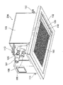
- FIG. FIG. 2 is an external view of the indoor unit shown in FIG. 1 as viewed obliquely from below
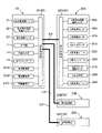
- FIG. 2 is a block diagram of the multi-type air conditioner shown in FIG. 1
- It is a flow chart of washing operation.
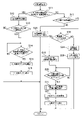
- 2 is a flowchart for explaining the operation of the multi-type air conditioner shown in FIG. 1 when a heating operation is requested.
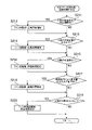
- 4 is a flow chart showing a procedure for determining the number of revolutions of the fan and the ventilation time in the indoor unit whose cleaning operation has been interrupted.
- FIG. 1 shows a configuration diagram of a multi-type air conditioner 1 according to an embodiment of the present disclosure.
- the multi-type air conditioner 1 includes an outdoor unit 10 and three indoor units 20A, 20B, and 20C. It is connected to the outdoor unit 10 via piping.
- the indoor unit 20A has an A-room heat exchanger 24A and an A-room fan 25A.
- the indoor unit 20B has a B room heat exchanger 24B and a B room fan 25B.
- the indoor unit 20C has a C-room heat exchanger 24C and a C-room fan 25C.
- the number of indoor units is three, but the number of indoor units can be any number of two or more. Also, in the following description, the room in which the indoor unit 20A is installed is called room A, the room in which 20B is installed is called room B, and the room in which the indoor unit 20C is installed is called room C.
- the outdoor unit 10 includes a compressor 11, a four-way switching valve 12, an outdoor heat exchanger 13, an outdoor fan 15, an accumulator 16, and three electric expansion valves EVA, EVB, EVC.
- One of the four ports of the four-way switching valve 12 is connected to the discharge side of the compressor 11, another one is connected to one end of the outdoor heat exchanger 13, and another one is connected to one end of the accumulator 16, Yet another one is connected to one end of A-chamber heat exchanger 24A, B-chamber heat exchanger 24B and C-chamber heat exchanger 24C via three refrigerant pipe connections 18A, 18B, 18C.
- the other end of the outdoor heat exchanger 13 is connected to one ends of three electric expansion valves EVA, EVB and EVC.
- the other ends of the three electric expansion valves EVA, EVB, and EVC are connected to the A-compartment heat exchanger 24A, the B-compartment heat exchanger 24B, and the C-compartment heat exchanger 24A, 17B, and 17C, respectively, via three refrigerant pipe connections 17A, 17B, and 17C. connected to the other end of the device 24C.
- the other end of the accumulator 16 is connected to the suction side of the compressor 11 .
- An A-room fan 25A, a B-room fan 25B, and a C-room fan 25C are arranged near the A-room heat exchanger 24A, the B-room heat exchanger 24B, and the C-room heat exchanger 24C, respectively.
- the A room fan 25A is driven by an A room fan motor 26A (see FIG. 3).
- the B room fan 25B and the C room fan 25C are also driven by indoor fan motors (not shown).
- Compressor 11, four-way selector valve 12, outdoor heat exchanger 13, electric expansion valves EVA, EVB, EVC, A-chamber heat exchanger 24A, B-chamber heat exchanger 24B and C-chamber heat exchanger 24C , and an accumulator 16 are connected by refrigerant pipes to form a refrigerant circuit 3 .
- the refrigerant circuit 3 uses, for example, slightly flammable R32 as a refrigerant.
- a discharge pipe temperature sensor 31 is arranged on the discharge side of the compressor 11 .
- An outdoor heat exchanger temperature sensor 32 for detecting the outdoor heat exchanger temperature is arranged in the outdoor heat exchanger 13, and an outdoor temperature sensor 33 for detecting the outdoor temperature is arranged near the outdoor heat exchanger 13. are placed.
- An A-room heat exchanger temperature sensor 45A for detecting the indoor heat exchanger temperature is arranged in the A-room heat exchanger 24A, and an A-room temperature sensor 46A for detecting the indoor temperature is arranged near the A-room heat exchanger 24A. and an A room humidity sensor 47A for detecting indoor humidity.
- a B-room heat exchanger temperature sensor 45B for detecting the indoor heat exchanger temperature is arranged in the B-room heat exchanger 24B, and a B-room temperature sensor 46B for detecting the indoor temperature is arranged near the B-room heat exchanger 24B. and a room B humidity sensor 47B for detecting indoor humidity.
- a C-chamber heat exchanger temperature sensor 45C for detecting the indoor heat exchanger temperature is arranged in the C-chamber heat exchanger 24C.
- a sensor 46C and a C-chamber humidity sensor 47C for detecting the indoor humidity are arranged.
- the indoor unit 20A includes a room A human sensor 21A (see FIG. 3) for detecting whether a person is in the A room using infrared rays, and an air sensor 21A (see FIG. 3).
- a room A humidification unit 22A (see FIG. 3) is arranged.
- the A-chamber humidification unit 22A may be a known one including a rotor in which an adsorbent such as silica gel is formed in a honeycomb shape or a porous multi-grain shape (see Japanese Patent No. 6743869).
- FIG. 2 is a perspective view of the indoor unit 20A viewed obliquely from below.
- the indoor unit 20A is a ceiling cassette type (ceiling embedded type) indoor unit.
- the three indoor units 20A, 20B, and 20C are all ceiling cassette type indoor units, but some or all of them may be wall-mounted or floor-mounted indoor units.
- the indoor unit 20A includes a casing body 101, a rectangular panel 102 attached to the lower side of the casing body 101, and a grill 103 detachably attached to the panel 102.
- the surface of the panel 102 has light emitting diodes (LEDs), and the A room display unit 28A (see FIG. 3) is provided.
- LEDs light emitting diodes
- a blowout port 110 is provided along the short side of the panel 102 on one side in the longitudinal direction of the panel 102 .
- a flap 120 is attached to the panel 102 .
- the flap 120 is driven by the A-chamber flap drive motor 27A (see FIG. 3) to be rotatable relative to the panel 102 within a predetermined angular range, thereby opening and closing the outlet 110 .
- FIG. 3 shows a state where the outlet 110 is closed by the flap 120 .
- a drain socket 107 protrudes from the side wall of the casing body 101 .
- a drain hose (not shown) is connected to the drain socket 107 from the outside.
- pipe connection portions 105 and 106 protrude from side walls of the casing main body 101 .
- Refrigerant pipes (not shown) are connected to the pipe connection portions 105 and 106 from the outside.
- Suspension fittings 111 to 113 protrude laterally from the casing main body 101 .
- an electrical component section 108 is arranged near the casing main body 101 .
- FIG. 3 is a block diagram of the air conditioner 1 according to this embodiment. Since the three indoor units 20A, 20B, and 20C have the same structure in this embodiment, the indoor unit 20A will be mainly described here. Also, the illustration of the indoor units 20B and 20C is simplified in FIG.
- the outdoor unit 10 includes an outdoor control unit 51 comprising a microcomputer including an arithmetic device and a storage device, an input/output circuit, and the like.
- the indoor units 20A, 20B, and 20C respectively include indoor controllers 52A, 52B, and 52C each including a microcomputer including an arithmetic device and a storage device, an input/output circuit, and the like.
- the outdoor control unit 51 and the indoor control unit 52A are connected by a communication line LA
- the outdoor control unit 51 and the indoor control unit 52B are connected by a communication line LB
- the outdoor control unit 51 and the indoor control unit 52C are connected by a communication line LC.
- the outdoor controller 51 and the three indoor controllers 52A, 52B, and 52C communicate with each other via communication lines LA, LB, and LC, so that the outdoor controller 51 and the indoor controllers 52A, 52B, and 52C operate as multi-type air It operates as the control section 50 of the harmony machine 1 .
- Temperature detection signals from the discharge pipe temperature sensor 31, the outdoor heat exchanger temperature sensor 32, and the outdoor temperature sensor 33 are supplied to the outdoor control unit 51.
- the outdoor control unit 51 also controls the compressor 11, the four-way switching valve 12, the outdoor fan motor 14, the electric expansion valves EVA, EVB, EVC, and the like.
- Detection signals from the A-room heat exchanger temperature sensor 45A, the A-room temperature sensor 46A, the A-room humidity sensor 47A, and the A-room human sensor 21A are supplied to the indoor control unit 52A.
- the indoor controller 52A also controls the A-room humidifying unit 22A, the A-room fan motor 26A, the A-room flap drive motor 27A, the A-room display unit 28A, the A-room communication unit 29A, and the like.
- the A-room communication unit 29A performs wireless communication with a user-operable remote controller (not shown) (hereinafter referred to as "remote controller").
- the control unit 50 controls the operation of the air conditioner 1 in response to commands from the remote controller.
- the remote control has a liquid crystal display unit or a light emitting diode (LED), and can notify the user by means of light, characters, graphics, or the like.
- LED light emitting diode
- control unit 50 rotates the air conditioning operation including the cooling operation and the heating operation, the A room fan 25A, the B room fan 25B and the C room fan 25C in each indoor unit.
- a cleaning operation which will be described later, can be executed.
- the outdoor control unit 51 switches the four-way switching valve 12 to the position indicated by the dotted line in FIG. start driving. At this time, the outdoor control unit 51 opens the electric expansion valve EVA to a predetermined degree of opening, while closing the electric expansion valves EVB and EVC.
- the high-temperature and high-pressure gas refrigerant discharged from the compressor 11 is condensed by heat exchange with the outdoor air in the outdoor heat exchanger 13 functioning as a condenser by the outdoor control unit 51 rotating the outdoor fan 15. It becomes a liquid refrigerant.
- the liquid refrigerant from the outdoor heat exchanger 13 reaches the A-room heat exchanger 24A after being decompressed by the electric expansion valve EVA.
- the indoor control unit 52A operates the A-room fan 25A
- the decompressed liquid refrigerant evaporates by heat exchange with the indoor air in the A-room heat exchanger 24A functioning as an evaporator, and becomes a gaseous refrigerant.
- the indoor control unit 52A moves the flap 120 to the position where the air outlet 110 opens, so that the air cooled by the room A heat exchanger 24A is discharged from the air outlet 110.
- the outdoor control unit 51 switches the four-way switching valve 2 to the solid line position shown in FIG. At this time, the outdoor controller 51 opens all the electric expansion valves EVA, EVB, and EVC to predetermined opening degrees. Therefore, when the indoor unit 20A performs the heating operation, the high-temperature refrigerant also flows into the other indoor units 20B and 20C. This is to prevent the refrigerant from staying in the indoor units 20B and 20C that do not perform the heating operation and in the refrigerant pipes before and after them.
- the high-temperature and high-pressure gas refrigerant discharged from the compressor 11 is condensed by heat exchange with indoor air in the A-room heat exchanger 24A functioning as a condenser by the indoor controller 52A operating the A-room fan 25A. and becomes a liquid refrigerant.
- the refrigerant from the A-chamber heat exchanger 24A, the B-chamber heat exchanger 24B, and the C-chamber heat exchanger 24C reaches the outdoor heat exchanger 13 after being decompressed by the electric expansion valves EVA, EVB, and EVC. .
- control unit 50 The details of control of the outdoor unit 10 and the indoor units 20A, 20B, and 20C by the control unit 50 are changed by commands from the remote controller.
- the remote controller By operating the remote controller, the user can request the multi-type air conditioner 1 to select heating operation or cooling operation, start operation, stop operation, set room temperature and air volume, and start and stop cleaning operation.
- step S1 when the remote control of the indoor unit 20A is operated to request the indoor unit 20A to perform the cleaning operation, in step S1, the control unit 50 operates the room A humidifying unit 22A until a predetermined time T1 elapses. . As a result, the air inside the indoor unit 20A is humidified. This humidification process makes it possible to increase the amount of water condensed on the surface of the A-compartment heat exchanger 24A in the next evaporator phase.
- the control unit 50 stops the compressor 11 without operating it.
- the controller 50 stops the room A humidifying unit 22A.
- step S1 may end when the humidity detected by the room A humidity sensor 47A reaches a predetermined value. Also, the humidification process in step S1 may be omitted.
- step S2 the controller 50 executes the evaporator phase of the cleaning operation. Specifically, the controller 50 switches the four-way switching valve 12 to the position indicated by the dotted line in FIG. 1 and starts the operation of the compressor 11 .
- the controller 50 also drives the room A fan motor 26A to rotate the room A fan 25A at a predetermined number of revolutions, and drives the room A flap drive motor 27A to move the flap 120 to the position where the outlet 110 opens. .
- the control unit 50 opens the electric expansion valve EVA to a predetermined degree of opening, while closing the electric expansion valves EVB and EVC.
- the A-room heat exchanger 24A functions as an evaporator as in the cooling operation, and the evaporator phase of the cleaning operation starts.
- the temperature of the A-compartment heat exchanger 24A becomes higher than 0° C. and below the dew point temperature, moisture in the air begins to condense on the surface of the A-compartment heat exchanger 24A. This condensed water can clean the dirt adhering to the surface of the A-chamber heat exchanger 24A.
- the temperature of the A-compartment heat exchanger 24A may be kept below the freezing point so that the surface of the A-compartment heat exchanger 24A is frosted with moisture in the air.
- the length of the evaporator phase is the predetermined time T2.
- the length of the evaporator phase is calculated by the control unit 50 from the environmental conditions (room temperature and humidity of room A, outdoor temperature). It may be the time until After the evaporator phase ends, the controller 50 stops the operation of the compressor 11 .
- step S3 the controller 50 executes the blowing phase of the cleaning operation. Specifically, the controller 50 continues from step S2 by driving the room A fan motor 26A to rotate the room A fan 25A. Then, the position of the flap 120 is maintained at the same position as in step S2. Since the compressor 11 is stopped in the blowing phase, the temperature of the A-room heat exchanger 24A is higher than the temperature of the A-room heat exchanger 24A in the evaporator phase. The temperature of the A-compartment heat exchanger 24A is usually higher than the dew point temperature. By rotating the A room fan 25A, the evaporation of the moisture condensed on the A room heat exchanger 24A can be accelerated.
- the number of rotations of the A-room fan 25A and the blowing time are changed according to environmental conditions and the like, as will be described later.
- the number of rotations and the blowing time of the room A fan 25A may be fixed at constant values. It should be noted that the compressor 11 does not have to be stopped if the temperature of the A-room heat exchanger 24A is higher than the temperature of the A-room heat exchanger 24A in the evaporator phase in the ventilation phase.
- the controller 50 executes the condenser phase of the cleaning operation. Specifically, the control unit 50 switches the four-way switching valve 12 to the position indicated by the solid line in FIG. 1 and starts the operation of the compressor 11 . Continuing from step S3, the controller 50 drives the room A fan motor 26A to rotate the room A fan 25A at a predetermined number of revolutions, and maintains the position of the flap 120 at the same position as in step S2. . At this time, the controller 50 opens all the electric expansion valves EVA, EVB, and EVC to predetermined opening degrees. As a result, the A-room heat exchanger 24A functions as a condenser as in the heating operation, and the condenser phase of the cleaning operation starts.
- the temperature of the A-compartment heat exchanger 24A is higher than the temperature of the A-compartment heat exchanger 24A in the ventilation phase. Therefore, the evaporation of moisture remaining on the surface of the A-compartment heat exchanger 24A can be further accelerated.
- the length of the condenser phase may be a predetermined time T4. After the condenser phase ends, the controller 50 stops the compressor 11 and the A-chamber fan 25A, drives the A-chamber flap drive motor 27A, and moves the flap 120 to a position where the outlet 110 is closed. Note that the condenser phase can be omitted, for example, if the blowing phase of step S3 is made sufficiently long.
- step S11 the control unit 50 determines whether both the indoor units 20A and 20B installed in the A room and the B room are in a shutdown state, or the two indoor units It is determined whether at least one of the machines 20A and 20B is in heating or fan operation. Then, if this condition is met (S11: YES), the controller 50 starts the heating operation in the indoor unit 20C in step S12. Specifically, the controller 50 moves the flap 120 of the indoor unit 20C to a position where the outlet 110 opens. If necessary, the four-way switching valve 2 is switched to the solid line position shown in FIG. 1 to adjust the rotational speed of the compressor 11 and the opening degrees of the electric expansion valves EVA, EVB, and EVC.
- the indoor units 20A and 20B are blowing air
- the air blowing operation of the indoor units 20A and 20B is temporarily stopped until the heating operation of the indoor unit 20C in the C room is completed.
- the indoor unit 20C may or may not be performing the cleaning operation or the air conditioning operation.
- step S13 the control unit 50 determines whether the one of the indoor units 20A and 20B that was in the shutdown state was in the cooling operation as the previous operation, and has not been operated even once after the end of the cooling operation. do. If this condition is met (S13: YES), the process proceeds to step S14.
- step S14 the control unit 50 determines that the indoor heat exchanger temperature detected by the A room heat exchanger temperature sensors 45A and 45B of the indoor units (one or both of the indoor units 20A and 20B) satisfying the condition of step S13 is A It is determined whether the room temperature is higher than the room temperature detected by the room temperature sensors 46A and 46B. This is a condition in which the moisture adhering to the indoor heat exchanger is easy to evaporate.
- step S15 the controller 50 controls the constant The A room fan 25A and the B room fan 25B are started to rotate at a rotational speed equal to or higher than the rotational speed. At this time, the flaps 120 of the indoor units 20A and 20B are maintained at the position of closing the outlet 110 .
- the three electric expansion valves EVA, EVB, and EVC are each opened to a predetermined degree of opening, so when the indoor unit 20C performs the heating operation, the high-temperature refrigerant also flows into the other indoor units 20A and 20B. . Therefore, in this embodiment, the determination in step S14 is repeated until it is detected that the indoor heat exchanger temperature is higher than the indoor temperature.
- step S16 the control unit 50 stops the room A fan 25A and the room B fan 25B, and opens the flaps related to the indoor units 20A and 20B. 120 is moved to a position where the outlet 110 is closed.
- the multi-type air conditioner 1 enters a state of waiting for the next instruction while executing the heating operation in the indoor unit 20C (hereinafter referred to as "heating operation state"). If the condition of step S13 is not met (S13: NO), the multi-type air conditioner 1 enters the heating operation state without rotating the A room fan 25A and the B room fan 25B (step S15).
- step S17 the control unit 50 determines whether at least one of the two indoor units 20A and 20B is in cleaning operation. Then, if this condition is met (S17: YES), in step S18, the controller 50 controls the indoor unit that is in cleaning operation (below, it is assumed that only the indoor unit 20A is in cleaning operation). determines whether the evaporator phase or the blower phase is running. If this condition is met (S18: YES), the process proceeds to step S19.
- step S19 the control unit 50 interrupts the cleaning operation in the indoor unit 20A and starts the heating operation in the indoor unit 20C.
- the four-way selector valve 2 is switched to the solid line position shown in FIG. 1, and all the electric expansion valves EVA, EVB, and EVC are opened to predetermined opening degrees.
- the refrigerant from the outdoor unit 10 flows through the A-room heat exchanger 24A, the B-room heat exchanger 24B, and the C-room heat exchanger 24C of the three indoor units 20A, 20B, and 20C.
- the rotation speed of the compressor 11, the rotation speed of the outdoor fan 15, and the rotation speed of the C room fan 25C are adjusted to values corresponding to the heating load in the indoor unit 20C, and the flap 120 of the indoor unit 20C is adjusted so that the air outlet 110 Move it to the open position.
- the room A fan 25A may be temporarily stopped, or may continue to rotate at the same number of revolutions as before until the start of step S22.
- step S20 the controller 50 determines whether the indoor heat exchanger temperature detected by the A-room heat exchanger temperature sensor 45A of the indoor unit 20A is higher than the indoor temperature detected by the A-room temperature sensor 46A. . Then, if this condition is met (S20: YES), in step S21, the control section 50 controls the number of rotations of the room A fan 25A and the blowing time before starting the rotation of the room A fan 25A in step S22. decide. Note that step S20 may be omitted, and step S21 may be performed in a state in which the indoor heat exchanger temperature is lower than or equal to the indoor temperature.
- step S211 the control unit 50 determines whether or not the request for the heating operation of the indoor unit 20C of room C has been made within a predetermined period.
- the predetermined period is a period between when the first time elapses after the start of the evaporator phase and when the second time elapses after the start of the blower phase.
- the first time is for example 1/8 to 1/3 of the length of the evaporator phase.
- the second time is, for example, 2/3 to 7/8 of the length of the blowing phase.
- step S212 the control unit 50 makes settings such that at least one of the number of rotations of the room A fan 25A and the air blowing time in step S22 is increased. change.
- step S212 the predetermined period is further divided into a plurality of sections, and at least one of the number of rotations of the room A fan 25A and the air blowing time is increased in the section where the amount of water adhering to the indoor heat exchanger is assumed to be greater.
- the setting may be changed so that the increment of either one becomes larger.
- the initial value before the blowing time is increased may be, for example, zero, or may be any other value.
- the initial value before the rotation speed of the A-room fan 25A is increased is the same as the constant rotation speed described in step S15, and is the lower limit that promotes the evaporation of moisture that may have adhered to the A-room heat exchanger 24A. value. If this condition is not met (S211: NO), the process proceeds to step S213 without changing the setting.
- step S213 the control unit 50 determines whether the evaporation temperature of the room A heat exchanger 24A during the cleaning operation of the room A indoor unit 20A was below freezing. If this condition is met (S213: YES), in step S214, the control unit 50 changes the setting so that at least one of the number of revolutions of the room A fan 25A and the blowing time in step S22 is increased. . This is because when the temperature of the A-compartment heat exchanger 24A is below the freezing point, it is considered that the surface of the A-compartment heat exchanger 24A is frosted, so the temperature of the A-compartment heat exchanger 24A is higher than the freezing point.
- step S215 without changing the setting.
- step S215 the control unit 50 determines whether the indoor unit 20A has been humidified (step S1 in FIG. 4) during the cleaning operation of the indoor unit 20A in room A. If this condition is met (S215: YES), in step S216, the control unit 50 changes the setting so that at least one of the number of revolutions of the room A fan 25A and the blowing time in step S22 is increased. . This is because the amount of water adhering to the surface of the A-room heat exchanger 24A increases when the indoor unit 20A is humidified compared to when the indoor unit 20A is not humidified. If this condition is not met (S215: NO), the process proceeds to step S217 without changing the setting.
- step S217 the control unit 50 determines the amount of water adhering to the A-room heat exchanger 24A under the environmental conditions in the A-room and outdoors. Specifically, in the combination of the room temperature of room A, the humidity of room A, and the outdoor temperature, the higher the room temperature of room A, the higher the humidity of room A, and the higher the outdoor temperature, the higher the heat exchanger for room A. Based on the fact that the amount of water adhering to 24A increases, it is determined to what extent the amount of water will be.
- step S219 the control unit 50 increases at least one of the rotational speed and air blowing time of the room A fan 25A in step S22 as the amount of water adhering to the room A heat exchanger 24A increases depending on the environmental conditions in the room A and outdoors. Change the setting so that the increment of either one is larger.
- step S219 the control unit 50 determines whether or not the A-room human sensor 21A in the A-room has detected that there is no person in the A-room. If this condition is met (S219: YES), in step S220, the control unit 50 changes the settings so that the rotation speed of the room A fan 25A in step S22 is increased and the blowing time is decreased. When there are no people in the A room, there is no concern that the warm air blown out from the indoor unit 20A will hit people, so the rotation speed of the A room fan 25A is increased, and accordingly the A room heat exchanger 24A is quickly closed. This is because the surface can be dried. It should be noted that it is not necessary to increase the number of revolutions of the room A fan 25A and change the blowing time. If this condition is not met (S219: NO), the process proceeds to step S22 without changing the setting.
- step S22 the control unit 50 executes a fan operation to start rotation of the room A fan 25A at the rotational speed of the room A fan 25A determined in step S21. At this time, the controller 50 maintains the flap 120 at the position where the outlet 110 opens. Note that the controller 50 sets the direction of rotation of the room A fan 25A during the blowing operation to be the same as during the air conditioning operation. Therefore, the air warmed by heat exchange with the high-temperature refrigerant sent from the outdoor unit 10 is discharged from the outlet 110 of the indoor unit 20A.
- step S23 the control unit 50 stops the room A fan 25A and opens the flap 120 of the indoor unit 20A to the outlet. 110 is moved to the closed position, and the multi-type air conditioner 1 is placed in the heating operation state.
- step S24 the indoor unit 20A is executing the condenser phase of the cleaning operation.
- the controller 50 starts heating operation in the indoor unit 20C. Specifically, the controller 50 moves the flap 120 of the indoor unit 20C to a position where the outlet 110 opens. Also, if necessary, the rotational speed of the compressor 11 and the opening of the electric expansion valve EVC are adjusted.
- step S25 the control unit 50 terminates the condenser phase when a predetermined time T4 has elapsed since the start of the condenser phase in the A chamber. Specifically, the control unit 50 stops the room A fan 25A, drives the room A flap drive motor 27A to move the flap 120 to the position where the outlet 110 closes, and puts the multi-type air conditioner 1 into the heating operation state. and
- step S17 If the condition of step S17 is not met (S17: NO), proceed to step S26.
- the indoor unit 20A or the indoor unit 20B is executing the cooling operation.
- a "first-push priority mode" is effective in the multi-type air conditioner 1, in which the first requested operation is prioritized.
- the control unit 50 does not perform the heating operation in the indoor unit 20C of the C room, and continues the cooling operation in the indoor unit 20A or the indoor unit 20B. Then, the control unit 50 notifies the user by displaying "heating operation cannot be performed due to mode conflict with another room” by the indoor unit 20C of room C or the remote controller. Then, the multi-type air conditioner 1 shifts to the heating operation state.
- Evaporation of moisture adhering to the A-room heat exchanger 24A can reduce the amount of moisture condensed on the casing body 101 of the indoor unit 20A, the ceiling of the A-room, and the like. Therefore, unexpected dripping of condensed moisture is suppressed.
- the refrigerant from the outdoor unit 10 is supplied to the A-room heat exchanger 24A and the B-room heat exchanger 24B of the three indoor units 20A, 20B, and 20C. and C-chamber heat exchanger 24C.
- the water adhering to the A-room heat exchanger 24A of the indoor unit 20A which was in the cleaning operation, is likely to evaporate. It is effective to diffuse the moisture adhering to the inside of the A chamber.
- the air blowing operation is performed to remove the moisture adhering to the room A heat exchanger 24A of the indoor unit 20A.
- (S22) it can be diffused into the A room.
- an appropriate air blower is adjusted according to the amount of moisture adhering to the surface of the A room heat exchanger 24A. It can be the number of revolutions of the room fan 25A and the blowing time.
- the rotation speed of the A room fan 25A is increased while the blowing time is decreased. In this way, when there is no person in the A room, hot air is not blown to the person, so it is possible to give priority to early removal of the moisture adhering to the A room heat exchanger 24A.
- the direction of rotation of the room A fan 25A during air blowing operation (S22) is the same as that during air conditioning operation.
- the direction of rotation of the room fan 25A is set to be opposite to that during the air conditioning operation.
- the cleaning operation in the indoor unit 20A is interrupted in step S19, the heating operation in the indoor unit 20C is started, and the blowing operation is started in step S22.
- the air blowing operation is started (specifically, the fan rotation speed is changed), and then the cleaning operation in the indoor unit 20A is interrupted (specifically, the compressor 11 ), and then the heating operation in the indoor unit 20C may be started.
- the indoor unit 20A is in the ventilation phase, the heating operation is started in the indoor unit 20C, and then the cleaning operation in the indoor unit 20A is interrupted (in detail, the fan is stopped). You may start the fan operation.
- steps S20 and S21 may be omitted, and the cleaning operation of the indoor unit 20A may be interrupted, the heating operation of the indoor unit 20C started, and the blowing operation of the indoor unit 20A started simultaneously.
- step S18 may be omitted and step S19 may be performed if the condition of step S17 is satisfied.
- the "first push priority mode" is effective in the multi-type air conditioner 1, but the “second push priority mode” may be effective in the multi-type air conditioner 1, and the C room has priority. It may be registered as a room.
- the control unit 50 performs the heating operation in the indoor unit 20C of room C, and suspends the cooling operation in the indoor unit 20A or the indoor unit 20B. Then, the user is notified by the indoor unit whose cooling operation has been interrupted or the remote control that "the cooling operation cannot be performed because priority is given to the heating operation of the other room".
- the operation may proceed to step S14 to evaporate the water adhering to the indoor heat exchanger of the indoor unit 20A or the indoor unit 20B.
Landscapes
- Engineering & Computer Science (AREA)
- Chemical & Material Sciences (AREA)
- Combustion & Propulsion (AREA)
- Mechanical Engineering (AREA)
- General Engineering & Computer Science (AREA)
- Air Conditioning Control Device (AREA)
Abstract
室外機と、第1ファン25A及び第1室内熱交換器24Aを含む第1室内機20Aと、第2ファン25C及び第2室内熱交換器24Cを含む第2室内機20Cと、制御部50とを備えた空気調和機が開示される。制御部50は、第1室内熱交換器24Aを蒸発器として機能させて第1室内熱交換器24Aを洗浄することを含む、第1室内機20Aでの洗浄運転、及び、第2室内熱交換器24Cを凝縮器として機能させる、第2室内機20Cでの暖房運転を実行可能である。制御部50は、第1室内機20Aでの洗浄運転の実行中に第2室内機20Cでの暖房運転が要求されると、第1室内機20Aでの洗浄運転を中断するとともに、第2室内機20Cでの暖房運転を実行し、第1室内機20Aの第1ファン25Aを回転させて送風運転を実行する。これによって、第1室内機20A又はその周辺での結露が抑制される。
Description
本開示は、空気調和機に関する。
空気中の水分を室内熱交換器の表面に結露又は着霜させ、その水分で室内熱交換器を洗浄処理する空気調和機が知られている。また、特許文献1には、1台の室外機と複数台の室内機とを有するマルチ型空気調和機において、所定の条件が成立すると、複数の室内熱交換器での洗浄処理を行う時間帯の少なくとも一部を重ねるようにすることが開示されている。
特許文献1には、複数の室内熱交換器で洗浄処理(洗浄運転)中である場合に、その中の一台の室内機に空調運転の指令があれば、複数の室内熱交換器での洗浄運転を中止し、指令を受けた室内機の空調運転を実行することが開示されている。しかし、ある室内機での洗浄運転中に別の室内機に対して暖房運転が要求されたとき、洗浄運転を中断して別の室内機での暖房運転を実行すると、洗浄運転によって室内熱交換器に付着した水分がそのまま放置されることになる。この水分が蒸発して、洗浄運転を中断した室内機又はその周辺に結露が生じることが懸念される。
本開示の目的は、他室での暖房運転のために洗浄運転を中断した室内機又はその周辺での結露を抑制できる空気調和機を提供することである。
本開示に係る空調室内機は、室外熱交換器を含む室外機と、前記室外機に冷媒配管を介して接続されており、第1ファン及び第1室内熱交換器を含む第1室内機と、前記室外機に前記冷媒配管を介して接続されており、第2ファン及び第2室内熱交換器を含む第2室内機と、制御部とを備えている。前記制御部は、前記第1室内熱交換器を蒸発器として機能させて前記第1室内熱交換器を洗浄することを含む、前記第1室内機での洗浄運転、及び、前記第2室内熱交換器を凝縮器として機能させる、前記第2室内機での暖房運転を実行可能であり、前記第1室内機での前記洗浄運転の実行中に前記第2室内機での前記暖房運転が要求されると、前記第1室内機での前記洗浄運転を中断するとともに、前記第2室内機での前記暖房運転を実行し、前記第1室内機の前記第1ファンを回転させて送風運転を実行する。
本開示によると、洗浄運転において第1室内機の第1室内熱交換器に付着した水分を送風運転によって第1室内機が設置された室内に拡散させることで、第1室内機又はその周辺での結露を抑制できる。
本開示の空気調和機においては、前記第2室内機での前記暖房運転実行時に、前記室外機からの冷媒が前記第1室内機の前記第1室内熱交換器及び前記第2室内機の前記第2室内熱交換器の両方を流れてよい。このような構成の空気調和機では、第1室内機の第1室内熱交換器に洗浄運転において付着した水分が洗浄運転後に蒸発しやすい。そのため、上記のように洗浄運転の中断後に送風運転を実行して第1室内機の第1室内熱交換器に付着した水分を拡散させることが有効となる。
本開示の空気調和機においては、前記第1室内機における空気の吹出口には可動式のフラップが配置されており、前記第1室内機での前記送風運転実行時に、前記第1室内機の前記フラップが前記吹出口を閉じる位置にあってよい。これによって、送風運転時における水飛散が抑制される。また、室内にいるユーザに空気が直接当たることを抑制できる。
本開示の空気調和機においては、前記第1室内機での前記送風運転実行時に、前記第1室内機の前記第1ファンが、前記暖房運転時とは逆方向に回転してよい。これによって、室内にいるユーザに空気が直接当たることを抑制できる。
本開示の空気調和機において、前記洗浄運転が、前記第1室内熱交換器を蒸発器として機能させて前記第1室内熱交換器の表面に結露又は着霜を生じさせる蒸発器フェーズと、前記蒸発器フェーズ後において、前記第1室内熱交換器の温度を前記蒸発器フェーズにおける前記第1室内熱交換器の温度よりも上昇させて前記第1ファンを回転させる送風フェーズとを含んでいてよい。この場合、前記制御部は、前記第1室内機での前記洗浄運転における前記蒸発器フェーズ及び前記送風フェーズのいずれかの実行中に前記第2室内機での前記暖房運転が要求されると、前記第1室内機での前記洗浄運転を中断するとともに、前記第2室内機での前記暖房運転を実行し、前記第1室内機の前記第1ファンを回転させて送風運転を実行してよい。これによって、蒸発器フェーズ又は送風フェーズの途中で洗浄運転を中断した場合においても、第1室内機の第1室内熱交換器に付着した水分を送風運転によって第1室内機が設置された室内に拡散させることができる。
また、本開示の空気調和機において、前記送風運転での前記第1室内機の前記第1ファンの回転数が可変であってよい。これによって、第1室内熱交換器の表面に付着した水分量に合わせた適切な第1ファンの回転数とすることができる。
一例として、前記洗浄運転が、前記第1室内熱交換器を蒸発器として機能させて前記第1室内熱交換器の表面に結露又は着霜を生じさせる蒸発器フェーズと、前記蒸発器フェーズ後において、前記第1室内熱交換器の温度を前記蒸発器フェーズにおける前記第1室内熱交換器の温度よりも上昇させて前記第1ファンを回転させる送風フェーズとを含んでいる場合に、前記制御部は、前記第1室内機での前記洗浄運転における前記蒸発器フェーズの開始から第1時間経過時と前記送風フェーズの開始から第2時間経過時との間に前記第2室内機での前記暖房運転が要求されたときの、前記第1室内機での前記送風運転における前記第1ファンの回転数を、前記第1室内機での前記洗浄運転における前記蒸発器フェーズの開始から前記第1時間経過前まで及び前記送風フェーズの開始から前記第2時間経過後に前記第2室内機での前記暖房運転が要求されたときの、前記第1室内機での前記送風運転における前記第1ファンの回転数よりも大きくしてよい。これによって、第1室内熱交換器の表面に多量の水分が付着していると想定される時に洗浄運転が中断された場合に第1ファンの回転数を大きくすることで、第1室内熱交換器の表面に付着した水分をより確実に削減できる。また、第1室内熱交換器の表面に付着している水分量が少ないと想定される時に洗浄運転が中断された場合に、室内に吹き出される空気が増えることがない。
別の例として、前記制御部は、前記第1室内機での前記洗浄運転における前記第1室内熱交換器の蒸発温度が氷点下であるときの、前記第1室内機での前記送風運転における前記第1ファンの回転数を、前記第1室内機での前記洗浄運転における前記第1室内熱交換器の蒸発温度が氷点よりも高いときの、前記第1室内機での前記送風運転における前記第1ファンの回転数よりも大きくしてよい。これによって、第1室内熱交換器の表面に付着した水分を除去するのに大きな風量を要すると想定される場合に第1ファンの風量を大きくすることで、第1室内熱交換器の表面に付着した水分をより確実に削減できる。
さらに別の例として、前記制御部は、前記第1室内機での前記洗浄運転において前記第1室内機の加湿を行ったときの、前記第1室内機での前記送風運転における前記第1ファンの回転数を、前記第1室内機での前記洗浄運転において前記第1室内機の加湿を行わないときの、前記第1室内機での前記送風運転における前記第1ファンの回転数よりも大きくしてよい。第1室内熱交換器の表面に多量の水分が付着していると想定される場合に第1ファンの回転数を大きくすることで、第1室内熱交換器の表面に付着した水分をより確実に削減できる。また、第1室内熱交換器の表面に付着している水分量が少ないと想定される場合に、室内に吹き出される空気が増えることがない。
他の例として、前記制御部は、前記第1室内機が設置された室内または室外での環境条件が前記第1室内機の前記第1室内熱交換器に付着する水分量が多くなる条件であるほど、前記第1室内機での前記送風運転における前記第1ファンの回転数を大きくしてよい。第1室内熱交換器の表面に多量の水分が付着していると想定される場合に第1ファンの回転数を大きくすることで、第1室内熱交換器の表面に付着した水分をより確実に削減できる。また、第1室内熱交換器の表面に付着している水分量が少ないと想定される場合に、室内に吹き出される空気が増えることがない。
また、さらなる他の例として、前記第1室内機が、人感センサをさらに含んでいる場合、前記制御部は、前記人感センサによって人がいないことが検知されたときの、前記第1室内機での前記送風運転における前記第1ファンの回転数を、前記人感センサによって人がいることが検知されたときの、前記第1室内機での前記送風運転における前記第1ファンの回転数よりも大きくしてよい。これによって、室内に人がいないときは空気が人に吹き付けられることがないので、熱交換器に付着した水分を早期に削減することを優先させることができる。
また、本開示の空気調和機において、前記送風運転での前記第1室内機の前記第1ファンの送風時間が可変であってもよい。これによって、第1室内熱交換器の表面に付着した水分量に合わせた適切な第1ファンの送風時間とすることができる。
一例として、前記洗浄運転が、前記第1室内熱交換器を蒸発器として機能させて前記第1室内熱交換器の表面に結露又は着霜を生じさせる蒸発器フェーズと、前記蒸発器フェーズ後において、前記第1室内熱交換器の温度を前記蒸発器フェーズにおける前記第1室内熱交換器の温度よりも上昇させて前記第1ファンを回転させる送風フェーズとを含んでいる場合に、前記制御部は、前記第1室内機での前記洗浄運転における前記蒸発器フェーズの開始から第1時間経過時と前記送風フェーズの開始から第2時間経過時との間に前記第2室内機での前記暖房運転が要求されたときの、前記第1室内機での前記送風運転における前記第1ファンの送風時間を、前記第1室内機での前記洗浄運転における前記蒸発器フェーズの開始から前記第1時間経過前まで及び前記送風フェーズの開始から前記第2時間経過後に前記第2室内機での前記暖房運転が要求されたときの、前記第1室内機での前記送風運転における前記第1ファンの送風時間よりも長くしてよい。これによって、第1室内熱交換器の表面に多量の水分が付着していると想定される時に洗浄運転が中断された場合に第1ファンの送風時間を長くすることで、第1室内熱交換器の表面に付着した水分をより確実に削減できる。また、第1室内熱交換器の表面に付着している水分量が少ないと想定される時に洗浄運転が中断された場合に、送風時間が長くなることがない。
別の例として、前記制御部は、前記第1室内機での前記洗浄運転における前記第1室内熱交換器の蒸発温度が氷点下であるときの、前記第1室内機での前記送風運転における前記第1ファンの送風時間を、前記第1室内機での前記洗浄運転における前記第1室内熱交換器の蒸発温度が氷点よりも高いときの、前記第1室内機での前記送風運転における前記第1ファンの送風時間よりも長くしてよい。これによって、第1室内熱交換器の表面に付着した水分を除去するのに長時間を要すると想定される場合に第1ファンの送風時間を長くすることで、第1室内熱交換器の表面に付着した水分をより確実に削減できる。
さらに別の例として、前記制御部は、前記第1室内機での洗浄運転において前記第1室内機の加湿を行ったときの、前記第1室内機での前記送風運転における前記第1ファンの送風時間を、前記第1室内機での洗浄運転において前記第1室内機の加湿を行わないときの、前記第1室内機での前記送風運転における前記第1ファンの送風時間よりも長くしてよい。第1室内熱交換器の表面に多量の水分が付着していると想定される場合に第1ファンの送風時間を長くすることで、第1室内熱交換器の表面に付着した水分をより確実に削減できる。また、第1室内熱交換器の表面に付着している水分量が少ないと想定される場合に、送風時間が長くなることがない。
他の例として、前記制御部は、前記第1室内機が設置された室内または室外での環境条件が前記第1室内機の前記第1室内熱交換器に付着する水分量が多くなる条件であるほど、前記第1室内機での前記送風運転における前記第1ファンの送風時間を長くしてよい。第1室内熱交換器の表面に多量の水分が付着していると想定される場合に第1ファンの送風時間を長くすることで、第1室内熱交換器の表面に付着した水分をより確実に削減できる。また、第1室内熱交換器の表面に付着している水分量が少ないと想定される場合に、送風時間が長くなることがない。
本開示の空気調和機において、前記第1室内機が天井カセットタイプであってよい。
(全体構造)
以下、本開示の実施形態について図面を参照しつつ説明する。図1には、本開示の一実施形態に係るマルチ型空気調和機1の構成図が示されている。マルチ型空気調和機1は、図1に示すように、室外機10と、3つの室内機20A、20B、20Cとを含んでおり、各室内機20A、20B、20Cが、冷媒が通過する冷媒配管を介して室外機10に接続されている。室内機20Aは、A室熱交換器24A及びA室ファン25Aを有している。室内機20Bは、B室熱交換器24B及びB室ファン25Bを有している。室内機20Cは、C室熱交換器24C及びC室ファン25Cを有している。なお、本実施形態では、室内機を3台としているが、室内機の台数は2台以上の任意の数とすることができる。また、以下の説明において、室内機20Aが設置された部屋をA室、20Bが設置された部屋をB室、20Cが設置された部屋をC室と称することとする。
以下、本開示の実施形態について図面を参照しつつ説明する。図1には、本開示の一実施形態に係るマルチ型空気調和機1の構成図が示されている。マルチ型空気調和機1は、図1に示すように、室外機10と、3つの室内機20A、20B、20Cとを含んでおり、各室内機20A、20B、20Cが、冷媒が通過する冷媒配管を介して室外機10に接続されている。室内機20Aは、A室熱交換器24A及びA室ファン25Aを有している。室内機20Bは、B室熱交換器24B及びB室ファン25Bを有している。室内機20Cは、C室熱交換器24C及びC室ファン25Cを有している。なお、本実施形態では、室内機を3台としているが、室内機の台数は2台以上の任意の数とすることができる。また、以下の説明において、室内機20Aが設置された部屋をA室、20Bが設置された部屋をB室、20Cが設置された部屋をC室と称することとする。
室外機10は、圧縮機11と、四路切換弁12と、室外熱交換器13と、室外ファン15と、アキュムレータ16と、3つの電動膨脹弁EVA、EVB、EVCとを含んでいる。四路切換弁12の4つのポートの1つが圧縮機11の吐出側に接続され、別の1つが室外熱交換器13の一端に接続され、さらに別の1つがアキュムレータ16の一端に接続され、さらに別の1つが3つの冷媒配管接続部18A、18B、18Cを介してA室熱交換器24A、B室熱交換器24B及びC室熱交換器24Cの一端に接続されている。室外熱交換器13の他端は、3つの電動膨脹弁EVA、EVB、EVCの一端に接続されている。3つの電動膨脹弁EVA、EVB、EVCの他端は、それぞれ、3つの冷媒配管接続部17A、17B、17Cを介して、A室熱交換器24A、B室熱交換器24B及びC室熱交換器24Cの他端に接続されている。アキュムレータ16の他端は、圧縮機11の吸入側に接続されている。A室熱交換器24A、B室熱交換器24B、C室熱交換器24Cの近傍には、A室ファン25A、B室ファン25B、C室ファン25Cがそれぞれ配置されている。A室ファン25Aは、A室ファンモータ26A(図3参照)によって駆動される。B室ファン25B、C室ファン25Cも、それぞれ図示しない室内ファンモータによって駆動される。
圧縮機11と、四路切換弁12と、室外熱交換器13と、電動膨脹弁EVA、EVB、EVCと、A室熱交換器24A、B室熱交換器24B及びC室熱交換器24Cと、アキュムレータ16とが、冷媒配管によって接続されて冷媒回路3が形成されている。この冷媒回路3には、冷媒として例えば微燃性のR32が用いられている。
圧縮機11の吐出側には、吐出管温度センサ31が配置されている。また、室外熱交換器13には室外熱交換器温度を検出する室外熱交換器温度センサ32が配置されていると共に、室外熱交換器13の近傍には室外温度を検出する室外温度センサ33が配置されている。
A室熱交換器24Aには、室内熱交換器温度を検出するA室熱交換器温度センサ45Aが配置され、A室熱交換器24Aの近傍には、室内温度を検出するA室温度センサ46A及び室内湿度を検出するA室湿度センサ47Aが配置されている。B室熱交換器24Bには、室内熱交換器温度を検出するB室熱交換器温度センサ45Bが配置され、B室熱交換器24Bの近傍には、室内温度を検出するB室温度センサ46B及び室内湿度を検出するB室湿度センサ47Bが配置されている。また、C室熱交換器24Cには、室内熱交換器温度を検出するC室熱交換器温度センサ45Cが配置され、C室熱交換器24Cの近傍には、室内温度を検出するC室温度センサ46C及び室内湿度を検出するC室湿度センサ47Cが配置されている。
なお、図1において図示を省略しているが、室内機20A内には、A室内に人間がいるかを赤外線によって検知するA室人感センサ21A(図3参照)と、室内機20A内の空気を加湿するA室加湿ユニット22A(図3参照)とが配置されている。室内機20B、20Cについても同様である。A室加湿ユニット22Aは、シリカゲルなどの吸着材がハニカム状又は多孔多粒状に形成されたロータを含む公知のものであってよい(特許第6743869号公報参照)。
図2は、室内機20Aを斜め下方から見た斜視図である。室内機20Aは、天井カセットタイプ(天井埋め込み型)の室内機である。なお、本実施形態において、3つの室内機20A、20B、20Cはすべて天井カセットタイプの室内機であるが、一部又は全部が壁掛型や床置き型の室内機であってもよい。
室内機20Aは、図2に示すように、ケーシング本体101と、ケーシング本体101の下側に取り付けられた矩形状のパネル102と、パネル102に着脱可能に取り付けられたグリル103とを含んでいる。なお、図2では図示省略しているが、パネル102の表面には、発光ダイオード(LED)を有しており、光や文字、図形などによってユーザへの報知を行うA室表示部28A(図3参照)が設けられている。
パネル102の長手方向の一方に、パネル102の短辺に沿って吹出口110が設けられている。また、パネル102には、フラップ120が取り付けられている。フラップ120は、A室フラップ駆動モータ27A(図3参照)によって駆動されることで所定角度範囲内でパネル102に対して回転可能であり、これによって吹出口110を開閉できる。図3は、フラップ120により吹出口110が閉じられた状態を示す。
ケーシング本体101の側壁からは、ドレンソケット107が突出している。ドレンソケット107には外部からドレンホース(図示せず)が接続される。さらに、ケーシング本体101の側壁からは、配管接続部105、106が突出している。配管接続部105、106には、外部から冷媒配管(図示せず)が接続される。ケーシング本体101からは、吊り金具111~113が側方に突出している。また、ケーシング本体101の近傍には、電装品部108が配置されている。
(制御系統)
次に、マルチ型空気調和機1の制御系統について説明する。図3は、本実施形態に係る空気調和機1のブロック図である。なお、本実施形態において3台の室内機20A、20B、20Cは同じ構造を有しているため、ここでは室内機20Aを中心に説明することとする。また、図3において室内機20B、20Cの図示を簡略化している。
次に、マルチ型空気調和機1の制御系統について説明する。図3は、本実施形態に係る空気調和機1のブロック図である。なお、本実施形態において3台の室内機20A、20B、20Cは同じ構造を有しているため、ここでは室内機20Aを中心に説明することとする。また、図3において室内機20B、20Cの図示を簡略化している。
室外機10は、演算装置と記憶装置とを含むマイクロコンピュータ及び入出力回路などからなる室外制御部51を含んでいる。室内機20A、20B、20Cは、それぞれ、演算装置と記憶装置とを含むマイクロコンピュータ及び入出力回路などからなる室内制御部52A、52B、52Cを含んでいる。室外制御部51と室内制御部52Aとは通信線LAによって接続され、室外制御部51と室内制御部52Bとは通信線LBによって接続され、室外制御部51と室内制御部52Cとは通信線LCによって接続されている。室外制御部51と3つの室内制御部52A、52B、52Cとが通信線LA、LB、LCを介して通信を行うことによって、室外制御部51及び室内制御部52A、52B、52Cがマルチ型空気調和機1の制御部50として動作する。
室外制御部51には、吐出管温度センサ31、室外熱交換器温度センサ32、及び、室外温度センサ33からの温度検出信号が供給される。また、室外制御部51は、圧縮機11、四路切換弁12、室外ファンモータ14、及び、電動膨脹弁EVA、EVB、EVCなどを制御する。
室内制御部52Aには、A室熱交換器温度センサ45A、A室温度センサ46A、A室湿度センサ47A及びA室人感センサ21Aからの検出信号が供給される。また、室内制御部52Aは、A室加湿ユニット22A、A室ファンモータ26A、A室フラップ駆動モータ27A、A室表示部28A及びA室通信ユニット29Aなどを制御する。A室通信ユニット29Aは、ユーザによる操作可能な図示しないリモートコントローラ(以下、「リモコン」と言う)との間で無線通信を行う。制御部50は、リモコンからの指令を受けて空気調和機1の動作を制御する。リモコンは液晶表示ユニット又は発光ダイオード(LED)を有しており、光や文字、図形などによってユーザへの報知を行うことができる。
本実施形態に係るマルチ型空気調和機1において、制御部50は、各室内機において、冷房運転及び暖房運転を含む空調運転、A室ファン25A、B室ファン25B及びC室ファン25Cを回転させる送風運転のほか、後述する洗浄運転を実行できる。
本実施形態に係るマルチ型空気調和機1において、室内機20Aで冷房運転を行う場合、室外制御部51は、四路切換弁12を図1に示す点線の位置に切り換えて、圧縮機11の運転を開始する。このとき、室外制御部51は、電動膨脹弁EVAを所定の開度に開く一方で、電動膨脹弁EVB、EVCは閉じた状態とする。そして、圧縮機11から吐出した高温高圧のガス冷媒は、室外制御部51が室外ファン15を回転させることで、凝縮器として機能する室外熱交換器13において室外空気との熱交換により凝縮して液冷媒となる。次に、室外熱交換器13からの液冷媒は、電動膨脹弁EVAで減圧された後、A室熱交換器24Aに到達する。室内制御部52AがA室ファン25Aを運転することで、減圧された液冷媒は、蒸発器として機能するA室熱交換器24Aにおいて室内空気との熱交換により蒸発してガス冷媒となり、圧縮機11の吸入側に戻る。また、室内制御部52Aがフラップ120を吹出口110が開く位置に移動させることにより、A室熱交換器24Aによって冷やされた空気が吹出口110から排出される。
一方、室内機20Aで暖房運転を行う場合、室外制御部51は、四路切換弁2を図1に示す実線の位置に切り換えて、圧縮機11の運転を開始する。このとき、室外制御部51は、すべての電動膨脹弁EVA、EVB、EVCをそれぞれ所定の開度に開く。したがって、室内機20Aで暖房運転を行うと、それ以外の室内機20B、20Cにも高温冷媒が流れ込む。これは暖房運転を実行しない室内機20B、20C及びその前後の冷媒配管内に冷媒が滞留しないようにするためである。そして、圧縮機11から吐出した高温高圧のガス冷媒は、室内制御部52AがA室ファン25Aを運転することで、凝縮器として機能するA室熱交換器24Aで室内空気との熱交換により凝縮して液冷媒となる。次に、A室熱交換器24A、B室熱交換器24B及びC室熱交換器24Cからの冷媒は、電動膨脹弁EVA、EVB、EVCで減圧された後、室外熱交換器13に到達する。室外制御部51が室外ファン15を回転させることで、減圧された冷媒は、蒸発器として機能する室外熱交換器13において室外空気との熱交換により蒸発してガス冷媒となり、圧縮機11の吸入側に戻る。また、室内制御部52Aがフラップ120を吹出口110が開く位置に移動させることにより、A室熱交換器24Aによって暖められた空気が吹出口110から排出される。
制御部50による室外機10及び室内機20A、20B、20Cの制御内容は、リモコンからの指令によって変更される。ユーザは、リモコンを操作することで、暖房運転と冷房運転の選択、運転開始、運転停止、室内温度及び風量の設定、洗浄運転の開始と停止をマルチ型空気調和機1に対して要求できる。
(洗浄運転)
次に、本実施形態においてマルチ型空気調和機1が実行する洗浄運転の詳細について、図4をさらに参照しつつ説明する。なお、以下の説明は、すべての室内機が運転を停止した状態で1台の室内機20Aに対して洗浄運転が要求され、洗浄運転が終了するまで他の室内機20B、20Cに対して空調運転が要求されないことを前提としている。
次に、本実施形態においてマルチ型空気調和機1が実行する洗浄運転の詳細について、図4をさらに参照しつつ説明する。なお、以下の説明は、すべての室内機が運転を停止した状態で1台の室内機20Aに対して洗浄運転が要求され、洗浄運転が終了するまで他の室内機20B、20Cに対して空調運転が要求されないことを前提としている。
まず、室内機20Aのリモコンが操作されて、室内機20Aに対して洗浄運転が要求されると、ステップS1において、制御部50は、所定時間T1が経過するまでA室加湿ユニット22Aを稼働させる。これによって、室内機20A内の空気が加湿される。この加湿処理によって、次の蒸発器フェーズにおいてA室熱交換器24Aの表面に結露する水分量を増やすことが可能となる。所定時間T1において、制御部50は、圧縮機11を運転せずに停止させている。所定時間T1が経過すると、制御部50は、A室加湿ユニット22Aを停止させる。なお、ステップS1は、A室湿度センサ47Aで検出される湿度が所定値となったときに終了してもよい。また、ステップS1の加湿処理を省略してよい。
続いて、ステップS2において、制御部50は、洗浄運転の蒸発器フェーズを実行する。詳細には、制御部50は、四路切換弁12を図1に示す点線の位置に切り換えて圧縮機11の運転を開始する。また、制御部50は、A室ファンモータ26Aを駆動してA室ファン25Aを所定回転数で回転させ、A室フラップ駆動モータ27Aを駆動してフラップ120を吹出口110が開く位置に移動させる。このとき、制御部50は、電動膨脹弁EVAを所定の開度に開く一方で、電動膨脹弁EVB、EVCは閉じた状態とする。これによって、冷房運転時と同様に、A室熱交換器24Aが蒸発器として機能し、洗浄運転の蒸発器フェーズが開始する。A室熱交換器24Aの温度が0℃よりも高く露点温度以下になると、A室熱交換器24Aの表面に空気中の水分が結露し始める。この結露水によってA室熱交換器24Aの表面に付着した汚れを洗浄できる。なお、このときA室熱交換器24Aの温度が氷点以下となるようにして、A室熱交換器24Aの表面に空気中の水分を着霜させてもよい。本実施形態において、蒸発器フェーズの長さは、所定時間T2としている。蒸発器フェーズの長さは、制御部50が環境条件(A室の室内温度と湿度、室外温度)から計算して求めた、洗浄に必要な量の水分がA室熱交換器24A上に結露するまでの時間であってもよい。蒸発器フェーズが終わると、制御部50は、圧縮機11の運転を停止させる。
次に、ステップS3において、制御部50は、洗浄運転の送風フェーズを実行する。詳細には、制御部50は、ステップS2から引き続いて、A室ファンモータ26Aを駆動してA室ファン25Aを回転させる。そして、フラップ120の位置をステップS2時と同じ位置に維持する。送風フェーズでは、圧縮機11が停止しているため、A室熱交換器24Aの温度が蒸発器フェーズにおけるA室熱交換器24Aの温度よりも上昇している。そして、通常、A室熱交換器24Aの温度は露点温度よりも高くなる。A室ファン25Aを回転させることによって、A室熱交換器24A上に結露した水分の蒸発を促進できる。本実施形態において、A室ファン25Aの回転数及び送風時間(送風フェーズの長さ)は、後述するように、環境条件などに応じて変更される。しかし、A室ファン25Aの回転数及び送風時間は、一定値に固定されていてもよい。なお、送風フェーズでは、A室熱交換器24Aの温度が蒸発器フェーズにおけるA室熱交換器24Aの温度よりも上昇していれば、圧縮機11を停止させなくてもよい。
ステップS4において、制御部50は、洗浄運転の凝縮器フェーズを実行する。詳細には、制御部50は、四路切換弁12を図1に示す実線の位置に切り換えて圧縮機11の運転を開始する。また、制御部50は、ステップS3から引き続いて、A室ファンモータ26Aを駆動してA室ファン25Aを所定回転数で回転させ、そして、フラップ120の位置をステップS2時と同じ位置に維持する。このとき、制御部50は、すべての電動膨脹弁EVA、EVB、EVCをそれぞれ所定の開度に開く。これによって、暖房運転時と同様に、A室熱交換器24Aが凝縮器として機能し、洗浄運転の凝縮器フェーズが開始する。凝縮器フェーズにおいては、A室熱交換器24Aの温度が送風フェーズにおけるA室熱交換器24Aの温度よりも上昇している。そのため、A室熱交換器24Aの表面に残っている水分の蒸発をより一層促進できる。凝縮器フェーズの長さは、所定時間T4であってよい。凝縮器フェーズが終わると、制御部50は、圧縮機11及びA室ファン25Aを停止させ、A室フラップ駆動モータ27Aを駆動してフラップ120を吹出口110が閉じる位置に移動させる。なお、凝縮器フェーズは、例えばステップS3の送風フェーズを十分に長くした場合には省略できる。
(暖房運転要求時の動作)
次に、本実施形態に係るマルチ型空気調和機1において、C室に設置された室内機20Cでの暖房運転が要求されたときの動作について、図5のフローチャートをさらに参照して説明する。以下の各ステップは制御部50によって実行される。
次に、本実施形態に係るマルチ型空気調和機1において、C室に設置された室内機20Cでの暖房運転が要求されたときの動作について、図5のフローチャートをさらに参照して説明する。以下の各ステップは制御部50によって実行される。
室内機20Cでの暖房運転が要求されると、ステップS11において、制御部50は、A室及びB室に設置された室内機20A、20Bが共に運転停止状態である、又は、2台の室内機20A、20Bの少なくともいずれかが暖房又は送風運転中であるかを判断する。そして、この条件に該当する場合(S11:YES)、制御部50は、ステップS12において室内機20Cでの暖房運転を開始する。詳細には、制御部50は、室内機20Cのフラップ120を吹出口110が開く位置に移動させる。また、必要であれば、四路切換弁2を図1に示す実線の位置に切り換え、圧縮機11の回転数及び電動膨脹弁EVA、EVB、EVCの開度を調整する。また、もし室内機20A、20Bが送風運転中であった場合、C室での室内機20Cでの暖房運転が終了するまで、室内機20A、20Bでの送風運転を一時停止する。なお、暖房運転が要求された時点で、室内機20Cは洗浄運転又は空調運転を実行していてもよいし、していなくてもよい。以下の説明においては、暖房運転が要求された時点で、室内機20Bはいずれの運転も実行していない休止状態であったと仮定している。
ステップS13において、制御部50は、室内機20A、20Bのうち運転停止状態であったものが、前回の運転として冷房運転をしており、当該冷房運転終了後に一度も運転されていないかを判断する。この条件に該当する場合(S13:YES)、ステップS14に進む。ステップS14において、制御部50は、ステップS13の条件を満たした室内機(室内機20A、20Bの一方又は両方)のA室熱交換器温度センサ45A、45Bで検出した室内熱交換器温度がA室温度センサ46A、46Bで検出した室内温度よりも高いかを判断する。これは室内熱交換器に付着した水分が蒸発しやすい条件である。そして、この条件に該当する場合(S14:YES)、A室熱交換器24A、24Bに付着している可能性がある水分の蒸発を促進するために、ステップS15において、制御部50は、一定回転数以上の回転数でのA室ファン25A、B室ファン25Bの回転を開始させる。このとき、室内機20A、20Bのフラップ120は、吹出口110を閉じる位置に維持される。なお、暖房運転時には3つの電動膨脹弁EVA、EVB、EVCがそれぞれ所定の開度に開かれるので、室内機20Cで暖房運転を行うと、それ以外の室内機20A、20Bにも高温冷媒が流れ込む。そのため、本実施形態では、室内熱交換器温度が室内温度よりも高いことが検出されるまで、ステップS14の判断を繰り返して行う。
A室ファン25A、B室ファン25Bの回転開始から所定時間が経過すると、ステップS16において、制御部50は、A室ファン25A、B室ファン25Bを停止させると共に、室内機20A、20Bに係るフラップ120を吹出口110が閉じる位置に移動させる。これによって、マルチ型空気調和機1は、室内機20Cでの暖房運転を実行しつつ次の指示を待機する状態(以下において「暖房運転状態」と称する)となる。ステップS13の条件に該当しない場合は(S13:NO)、A室ファン25A、B室ファン25Bを回転(ステップS15)させることなく、マルチ型空気調和機1は暖房運転状態となる。
ステップS11の条件に該当しない場合(S11:NO)、ステップS17において、制御部50は、2台の室内機20A、20Bの少なくともいずれかが洗浄運転中であるかを判断する。そして、この条件に該当する場合(S17:YES)、ステップS18において、制御部50は、洗浄運転中の室内機(以下では、室内機20Aだけが洗浄運転中であると仮定して説明する)が、蒸発器フェーズ又は送風フェーズの実行中であるかを判断する。この条件に該当する場合(S18:YES)、ステップS19に進む。
ステップS19において、制御部50は、室内機20Aでの洗浄運転を中断し、室内機20Cでの暖房運転を開始する。詳細には、四路切換弁2を図1に示す実線の位置に切り換え、すべての電動膨脹弁EVA、EVB、EVCをそれぞれ所定の開度に開く。これによって、室外機10からの冷媒が、3つの室内機20A、20B、20CのA室熱交換器24A、B室熱交換器24B及びC室熱交換器24Cを流れる。また、圧縮機11の回転数、室外ファン15の回転数、C室ファン25Cの回転数を室内機20Cでの暖房負荷に合わせた値に調整し、室内機20Cのフラップ120を吹出口110が開く位置に移動させる。A室ファン25Aは一旦停止させてもよいし、ステップS22の開始までの間、今までと同じ回転数で回転を継続させてもよい。
次に、ステップS20において、制御部50は、室内機20AのA室熱交換器温度センサ45Aで検出した室内熱交換器温度がA室温度センサ46Aで検出した室内温度よりも高いかを判断する。そして、この条件に該当する場合(S20:YES)、ステップS21において、制御部50は、ステップS22でA室ファン25Aの回転を開始するのに先だって、A室ファン25Aの回転数及び送風時間を決定する。なお、ステップS20を省略し、室内熱交換器温度が室内温度よりも低い又は同じ温度の状態でステップS21に進んでもよい。
ここで、ステップS22におけるA室ファン25Aの回転数及び送風時間の決定手順の詳細について、図6を参照して説明する。
まず、ステップS211において、制御部50は、C室の室内機20Cでの暖房運転の要求が所定期間内にあったかを判断する。ここで、所定期間は、蒸発器フェーズの開始から第1時間経過時と送風フェーズの開始から第2時間経過時との間の期間である。第1時間は、例えば蒸発器フェーズの長さの1/8~1/3の時間である。第2時間は、例えば送風フェーズの長さの2/3~7/8の時間である。そして、この条件に該当する場合(S211:YES)、ステップS212において、制御部50は、ステップS22でのA室ファン25Aの回転数及び送風時間の少なくともいずれか一方が増加するように、設定を変更する。これは、当該所定期間内においては、蒸発器フェーズの開始から第1時間が経過する以前の蒸発器フェーズ初期、及び、送風フェーズの開始から第2時間が経過した以降の送風フェーズ末期と比べると、室内熱交換器に付着している水分量が多いと想定されるからである。なお、室内熱交換器に付着している水分量は、蒸発器フェーズの終了時点でピークとなり、この時点から離れるほど少なくなることが想定される。したがって、ステップS212において、所定期間を複数の区間にさらに分割し、室内熱交換器に付着している水分量が多いと想定される区間ほど、A室ファン25Aの回転数及び送風時間の少なくともいずれか一方の増加分が大きくなるように、設定を変更してもよい。
送風時間の増加前の初期値は例えばゼロであってもよいし、それ以外の値であってもよい。A室ファン25Aの回転数の増加前の初期値は、ステップS15で説明した一定回転数と同じであり、A室熱交換器24Aに付着している可能性がある水分の蒸発を促進する下限値である。また、この条件に該当しない場合(S211:NO)、設定を変更することなくステップS213に進む。
ステップS213において、制御部50は、A室の室内機20Aでの洗浄運転におけるA室熱交換器24Aの蒸発温度が氷点下であったかを判断する。この条件に該当する場合(S213:YES)、ステップS214において、制御部50は、ステップS22でのA室ファン25Aの回転数及び送風時間の少なくともいずれか一方が増加するように、設定を変更する。これは、A室熱交換器24Aの温度が氷点以下であった場合、A室熱交換器24Aの表面に着霜していると考えられるので、A室熱交換器24Aの温度が氷点よりも高かった場合と比較して、A室熱交換器24Aの表面を乾燥させるまでの合計風量(風量の時間積分値)を多くする必要があるからである。また、この条件に該当しない場合(S213:NO)、設定を変更することなくステップS215に進む。
ステップS215において、制御部50は、A室の室内機20Aでの洗浄運転において室内機20Aの加湿処理(図4のステップS1)を行ったかを判断する。この条件に該当する場合(S215:YES)、ステップS216において、制御部50は、ステップS22でのA室ファン25Aの回転数及び送風時間の少なくともいずれか一方が増加するように、設定を変更する。これは、室内機20Aを加湿処理した場合、室内機20Aの加湿処理をしない場合と比較して、A室熱交換器24Aの表面に付着した水分量が多くなるからである。また、この条件に該当しない場合(S215:NO)、設定を変更することなくステップS217に進む。
ステップS217において、制御部50は、A室内及び室外での環境条件がA室熱交換器24Aに付着する水分量をどの程度の量とする条件であるかを判断する。具体的には、A室の室温とA室の湿度と室外温度との組合せにおいて、A室の室温が高くなるほど、A室の湿度が高くなるほど、室外温度が高くなるほど、それぞれA室熱交換器24Aに付着する水分量が多くなることに基づいて、水分量がどの程度の量となるかを判断する。そして、A室熱交換器24Aに付着する水分量を基準量未満とする環境条件である場合は(S217:NO)、ステップS219に進み、A室熱交換器24Aに付着する水分量を基準量以上とする環境条件である場合は(S217:YES)、ステップS218に進む。ステップS218において、制御部50は、A室内及び室外での環境条件によってA室熱交換器24Aに付着する水分量が多くなるほど、ステップS22でのA室ファン25Aの回転数及び送風時間の少なくともいずれか一方の増加分が大きくなるように、設定を変更する。
ステップS219において、制御部50は、A室のA室人感センサ21AによってA室内に人がいないことが検知されたかを判断する。この条件に該当する場合(S219:YES)、ステップS220において、制御部50は、ステップS22でのA室ファン25Aの回転数が増加し且つ送風時間が減少するように、設定を変更する。これは、A室内に人がいない場合、室内機20Aから吹き出される温風が人に当たる懸念がないので、A室ファン25Aの回転数を増加させ、それに伴って早期にA室熱交換器24Aの表面を乾燥させることができるからである。なお、A室ファン25Aの回転数を増加させて、送風時間を変更しなくてもよい。また、この条件に該当しない場合(S219:NO)、設定を変更することなくステップS22に進む。
図6において説明した5つのファン回転数及び送風時間の変更手順は、これらの中の1つだけを行うようにしてもよいし、2つ以上の任意の数の手順を組み合わせて行うようにしてもよいし、1つも行わなくてもよい。
ステップS22において、制御部50は、S21で決定されたA室ファン25Aの回転数により、A室ファン25Aの回転を開始させる送風運転を実行する。このとき、制御部50は、フラップ120を吹出口110が開く位置に維持したままとする。なお、制御部50は、この送風運転におけるA室ファン25Aの回転方向を、空調運転時と同じとする。そのため、室外機10から送られた高温の冷媒との熱交換によって暖められた空気が、室内機20Aの吹出口110から排出される。
ステップS22でのA室ファン25Aの回転開始からS21で決定された送風時間が経過すると、ステップS23において、制御部50は、A室ファン25Aを停止させると共に、室内機20Aのフラップ120を吹出口110が閉じる位置に移動させ、マルチ型空気調和機1を暖房運転状態とする。
ステップS18の条件に該当しない場合(S18:NO)、ステップS24に進む。この場合、室内機20Aは洗浄運転の凝縮器フェーズの実行中であることになる。ステップS24において、制御部50は、室内機20Cでの暖房運転を開始する。詳細には、制御部50は、室内機20Cのフラップ120を吹出口110が開く位置に移動させる。また、必要であれば、圧縮機11の回転数及び電動膨脹弁EVCの開度を調整する。次に、ステップS25において、制御部50は、A室における凝縮器フェーズの開始から所定時間T4が経過したときに、当該凝縮器フェーズを終了させる。詳細には、制御部50は、A室ファン25Aを停止させ、A室フラップ駆動モータ27Aを駆動してフラップ120を吹出口110が閉じる位置に移動させ、マルチ型空気調和機1を暖房運転状態とする。
ステップS17の条件に該当しない場合(S17:NO)、ステップS26に進む。この場合、室内機20A又は室内機20Bが冷房運転を実行中であることになる。本実施形態においては、2台以上の室内機で共に空調運転を実行させる要求があった場合、先に要求された運転を優先させる「先押し優先モード」がマルチ型空気調和機1において有効であるとする。そのため、制御部50は、C室の室内機20Cでの暖房運転を実行せず、室内機20A又は室内機20Bでの冷房運転を継続する。そして、制御部50は、C室の室内機20C又はリモコンにより、「他室とのモードバッティングにより暖房運転できない」旨の表示によるユーザへの報知を行う。そして、マルチ型空気調和機1は暖房運転状態へと移行する。
(実施形態の効果)
本実施形態では、A室の室内機20Aでの洗浄運転が蒸発器フェーズ又は送風フェーズであるときに他の室内機20Cでの暖房運転の要求があった場合に、室内機20Aでの洗浄運転を中断して、室内機20Cでの暖房運転を実行する(S19)。そのため、暖房運転を洗浄運転よりも優先させることができる。また、室内機20AのA室熱交換器24Aに付着した水分を送風運転(S22)によってA室内に拡散させるので、A室熱交換器24Aでのカビの発生を抑制できると共に、室内機20AのA室熱交換器24Aに付着した水分の蒸発によって室内機20Aのケーシング本体101やA室内の天井などに結露する水分量を減らすことができる。したがって、結露した水分の予期せぬ滴下が抑制される。
本実施形態では、A室の室内機20Aでの洗浄運転が蒸発器フェーズ又は送風フェーズであるときに他の室内機20Cでの暖房運転の要求があった場合に、室内機20Aでの洗浄運転を中断して、室内機20Cでの暖房運転を実行する(S19)。そのため、暖房運転を洗浄運転よりも優先させることができる。また、室内機20AのA室熱交換器24Aに付着した水分を送風運転(S22)によってA室内に拡散させるので、A室熱交換器24Aでのカビの発生を抑制できると共に、室内機20AのA室熱交換器24Aに付着した水分の蒸発によって室内機20Aのケーシング本体101やA室内の天井などに結露する水分量を減らすことができる。したがって、結露した水分の予期せぬ滴下が抑制される。
また、本実施形態では、室内機20Cでの暖房運転を実行中に、室外機10からの冷媒が、3つの室内機20A、20B、20CのA室熱交換器24A、B室熱交換器24B及びC室熱交換器24Cを流れる。このような場合、洗浄運転をしていた室内機20AのA室熱交換器24Aに付着した水分が蒸発しやすいため、上記のように送風運転(S22)を実行してA室熱交換器24Aに付着した水分をA室内に拡散させることが有効となる。
また、本実施形態では、A室の室内機20Aでの洗浄運転が蒸発器フェーズ又は送風フェーズの途中で中断した場合においても、室内機20AのA室熱交換器24Aに付着した水分を送風運転(S22)によってA室内に拡散させることができる。
さらに、本実施形態では、送風運転(S22)でのA室ファン25Aの回転数及び送風時間が可変であるため、A室熱交換器24Aの表面に付着した水分量等に合わせた適切なA室ファン25Aの回転数及び送風時間とすることができる。
具体的には、C室での暖房運転の要求が所定期間内にあった場合、A室熱交換器24Aの蒸発温度が氷点下であった場合、室内機20Aで加湿処理(S1)を行った場合、及び、A室熱交換器24Aの表面に付着する水分量が基準量以上となる環境条件である場合には、それぞれ、A室ファン25Aの回転数及び送風時間の少なくともいずれか一方を増加させている。これによって、A室熱交換器24Aの表面に付着した水分をより確実に削減しつつ、A室内に吹き出される温風の風量及び送風時間の増加を抑制できる。さらに、人間がA室内にいない場合には、A室ファン25Aの回転数を増加させる一方において送風時間を減少させている。このようにA室内に人がいないときは温風が人に吹き付けられることがないので、A室熱交換器24Aに付着した水分を早期に除去することを優先させることができる。
(第1変形例)
上述した実施形態では、ステップS219においてA室人感センサ21Aを用いて人の検知を行っているが、第1変形例では、このような検知を行わない。そして、上述した実施形態では、送風運転時(S22)においてフラップ120を吹出口110が開く位置に維持したままとするが、第1変形例では、制御部50は、送風運転時(S22)において、フラップ120を吹出口110が閉じる位置に移動させる。これによって、A室熱交換器24Aの表面に付着した水分に起因した水滴のA室内への飛散を抑制できる。また、A室内にユーザがいる場合であっても、ユーザに温風が直接当たることを抑制できる。
上述した実施形態では、ステップS219においてA室人感センサ21Aを用いて人の検知を行っているが、第1変形例では、このような検知を行わない。そして、上述した実施形態では、送風運転時(S22)においてフラップ120を吹出口110が開く位置に維持したままとするが、第1変形例では、制御部50は、送風運転時(S22)において、フラップ120を吹出口110が閉じる位置に移動させる。これによって、A室熱交換器24Aの表面に付着した水分に起因した水滴のA室内への飛散を抑制できる。また、A室内にユーザがいる場合であっても、ユーザに温風が直接当たることを抑制できる。
(第2変形例)
上述した実施形態では、送風運転時(S22)におけるA室ファン25Aの回転方向を空調運転時と同じ方向としているが、第2変形例では、制御部50は、送風運転時(S22)におけるA室ファン25Aの回転方向を空調運転時とは逆方向とする。これによって、A室熱交換器24Aの表面に付着した水分に起因した水滴のA室内への飛散を抑制できる。また、A室内にユーザがいる場合であっても、ユーザに温風が直接当たることを抑制できる。
上述した実施形態では、送風運転時(S22)におけるA室ファン25Aの回転方向を空調運転時と同じ方向としているが、第2変形例では、制御部50は、送風運転時(S22)におけるA室ファン25Aの回転方向を空調運転時とは逆方向とする。これによって、A室熱交換器24Aの表面に付着した水分に起因した水滴のA室内への飛散を抑制できる。また、A室内にユーザがいる場合であっても、ユーザに温風が直接当たることを抑制できる。
(その他の変形例)
上述した実施形態では、ステップS19において室内機20Aでの洗浄運転を中断し且つ室内機20Cでの暖房運転を開始し、ステップS22において送風運転を開始しているが、これら3つの順序を入れ替えてもよい。例えば、室内機20Aが蒸発器フェーズであった場合には、送風運転を開始(詳細にはファン回転数を変更)してから室内機20Aでの洗浄運転を中断し(詳細には圧縮機11を停止させ)、その後に室内機20Cでの暖房運転を開始してもよい。また、室内機20Aが送風フェーズであった場合には、室内機20Cでの暖房運転を開始し、その後に室内機20Aでの洗浄運転を中断し(詳細にはファンを停止し)、さらにその後に送風運転を開始してもよい。さらに、ステップS20及び21を省略し、室内機20Aでの洗浄運転の中断と、室内機20Cでの暖房運転の開始と、室内機20Aでの送風運転の開始とを同時に行ってもよい。また、ステップS18を省略し、ステップS17の条件を満たす場合には、ステップS19を行うようにしてもよい。
上述した実施形態では、ステップS19において室内機20Aでの洗浄運転を中断し且つ室内機20Cでの暖房運転を開始し、ステップS22において送風運転を開始しているが、これら3つの順序を入れ替えてもよい。例えば、室内機20Aが蒸発器フェーズであった場合には、送風運転を開始(詳細にはファン回転数を変更)してから室内機20Aでの洗浄運転を中断し(詳細には圧縮機11を停止させ)、その後に室内機20Cでの暖房運転を開始してもよい。また、室内機20Aが送風フェーズであった場合には、室内機20Cでの暖房運転を開始し、その後に室内機20Aでの洗浄運転を中断し(詳細にはファンを停止し)、さらにその後に送風運転を開始してもよい。さらに、ステップS20及び21を省略し、室内機20Aでの洗浄運転の中断と、室内機20Cでの暖房運転の開始と、室内機20Aでの送風運転の開始とを同時に行ってもよい。また、ステップS18を省略し、ステップS17の条件を満たす場合には、ステップS19を行うようにしてもよい。
上述した実施形態では、「先押し優先モード」がマルチ型空気調和機1において有効であるが、「後押し優先モード」がマルチ型空気調和機1において有効であってもよいし、C室が優先部屋として登録されていてもよい。これらの場合、ステップS26において、制御部50は、C室の室内機20Cでの暖房運転を実行し、室内機20A又は室内機20Bの冷房運転を中断する。そして、冷房運転を中断した室内機又はリモコンにより、「他室の暖房運転を優先させるために冷房運転できない」旨の表示によるユーザへの報知を行う。この場合、室内機20A又は室内機20Bの冷房運転を中断した後、ステップS14に進んで室内機20A又は室内機20Bの室内熱交換器に付着した水分を蒸発させる運転を行ってもよい。
以上、実施形態を説明したが、特許請求の範囲の趣旨及び範囲から逸脱することなく、形態や詳細の多様な変更が可能なことが理解されるであろう。
3 冷媒回路
10 室外機
11 圧縮機
12 四路切換弁
13 室外熱交換器
16 アキュムレータ
17A、17B、17C 冷媒配管接続部
18A、18B、18C 冷媒配管接続部
20A、20B、20C 室内機
24A A室熱交換器
24B B室熱交換器
24C C室熱交換器
25A A室ファン
25B B室ファン
25C C室ファン
31 吐出管温度センサ
32 室外熱交換器温度センサ
33 室外温度センサ
45A A室熱交換器温度センサ
45B B室熱交換器温度センサ
45C C室熱交換器温度センサ
46A A室温度センサ
46B B室温度センサ
46C C室温度センサ
EVA、EVB、EVC 電動膨脹弁
10 室外機
11 圧縮機
12 四路切換弁
13 室外熱交換器
16 アキュムレータ
17A、17B、17C 冷媒配管接続部
18A、18B、18C 冷媒配管接続部
20A、20B、20C 室内機
24A A室熱交換器
24B B室熱交換器
24C C室熱交換器
25A A室ファン
25B B室ファン
25C C室ファン
31 吐出管温度センサ
32 室外熱交換器温度センサ
33 室外温度センサ
45A A室熱交換器温度センサ
45B B室熱交換器温度センサ
45C C室熱交換器温度センサ
46A A室温度センサ
46B B室温度センサ
46C C室温度センサ
EVA、EVB、EVC 電動膨脹弁
Claims (17)
- 室外熱交換器(13)を含む室外機(10)と、
前記室外機(10)に冷媒配管を介して接続されており、第1ファン(25A)及び第1室内熱交換器(24A)を含む第1室内機(20A)と、
前記室外機(10)に前記冷媒配管を介して接続されており、第2ファン(25C)及び第2室内熱交換器(24C)を含む第2室内機(20C)と、
制御部(50)と、を備え、
前記制御部(50)は、
前記第1室内熱交換器(24A)を蒸発器として機能させて前記第1室内熱交換器(24A)を洗浄することを含む、前記第1室内機(20A)での洗浄運転、及び、前記第2室内熱交換器(24C)を凝縮器として機能させる、前記第2室内機(20C)での暖房運転を実行可能であり、
前記第1室内機(20A)での前記洗浄運転の実行中に前記第2室内機(20C)での前記暖房運転が要求されると、前記第1室内機(20A)での前記洗浄運転を中断するとともに、前記第2室内機(20C)での前記暖房運転を実行し、前記第1室内機(20A)の前記第1ファン(25A)を回転させて送風運転を実行する空気調和機(1)。 - 前記第2室内機(20C)での前記暖房運転実行時に、前記室外機からの冷媒が前記第1室内機(20A)の前記第1室内熱交換器(24A)及び前記第2室内機(20C)の前記第2室内熱交換器(24C)の両方を流れる請求項1に記載の空気調和機(1)。
- 前記第1室内機(20A)における空気の吹出口(110)には可動式のフラップ(120)が配置されており、
前記第1室内機(20A)での前記送風運転実行時に、前記第1室内機(20A)の前記フラップ(120)が前記吹出口(110)を閉じる位置にある請求項1又は2に記載の空気調和機(1)。 - 前記第1室内機(20A)での前記送風運転実行時に、前記第1室内機(20A)の前記第1ファン(25A)が、前記暖房運転時とは逆方向に回転する請求項1又は2に記載の空気調和機(1)。
- 前記洗浄運転が、前記第1室内熱交換器(24A)を蒸発器として機能させて前記第1室内熱交換器(24A)の表面に結露又は着霜を生じさせる蒸発器フェーズ(S2)と、前記蒸発器フェーズ(S2)後において、前記第1室内熱交換器(24A)の温度を前記蒸発器フェーズ(S2)における前記第1室内熱交換器(24A)の温度よりも上昇させて前記第1ファン(25A)を回転させる送風フェーズ(S3)とを含んでおり、
前記制御部(50)は、
前記第1室内機(20A)での前記洗浄運転における前記蒸発器フェーズ(S2)及び前記送風フェーズ(S3)のいずれかの実行中に前記第2室内機(20C)での前記暖房運転が要求されると、前記第1室内機(20A)での前記洗浄運転を中断するとともに、前記第2室内機(20C)での前記暖房運転を実行し、前記第1室内機(20A)の前記第1ファン(25A)を回転させて送風運転を実行する請求項1~4のいずれか1項に記載の空気調和機(1)。 - 前記送風運転での前記第1室内機(20A)の前記第1ファン(25A)の回転数が可変である請求項1~5のいずれか1項に記載の空気調和機(1)。
- 前記洗浄運転が、前記第1室内熱交換器(24A)を蒸発器として機能させて前記第1室内熱交換器の表面に結露又は着霜を生じさせる蒸発器フェーズ(S2)と、前記蒸発器フェーズ(S2)後において、前記第1室内熱交換器(24A)の温度を前記蒸発器フェーズ(S2)における前記第1室内熱交換器(24A)の温度よりも上昇させて前記第1ファン(25A)を回転させる送風フェーズ(S3)とを含んでおり、
前記制御部(50)は、
前記第1室内機(20A)での前記洗浄運転における前記蒸発器フェーズ(S2)の開始から第1時間経過時と前記送風フェーズ(S3)の開始から第2時間経過時との間に前記第2室内機(20C)での前記暖房運転が要求されたときの、前記第1室内機(20A)での前記送風運転における前記第1ファン(25A)の回転数を、前記第1室内機(20A)での前記洗浄運転における前記蒸発器フェーズ(S2)の開始から前記第1時間経過前まで及び前記送風フェーズ(S3)の開始から前記第2時間経過後に前記第2室内機(20C)での前記暖房運転が要求されたときの、前記第1室内機(20A)での前記送風運転における前記第1ファン(25A)の回転数よりも大きくする請求項6に記載の空気調和機(1)。 - 前記制御部(50)は、
前記第1室内機(20A)での前記洗浄運転における前記第1室内熱交換器(24A)の蒸発温度が氷点下であるときの、前記第1室内機(20A)での前記送風運転における前記第1ファン(25A)の回転数を、前記第1室内機(20A)での前記洗浄運転における前記第1室内熱交換器(24A)の蒸発温度が氷点よりも高いときの、前記第1室内機(20A)での前記送風運転における前記第1ファン(25A)の回転数よりも大きくする請求項6又は7に記載の空気調和機(1)。 - 前記制御部(50)は、前記第1室内機(20A)での前記洗浄運転において前記第1室内機(20A)の加湿を行ったときの、前記第1室内機(20A)での前記送風運転における前記第1ファン(25A)の回転数を、前記第1室内機(20A)での前記洗浄運転において前記第1室内機(20A)の加湿を行わないときの、前記第1室内機(20A)での前記送風運転における前記第1ファン(25A)の回転数よりも大きくする請求項6~8のいずれか1項に記載の空気調和機(1)。
- 前記制御部(50)は、前記第1室内機(20A)が設置された室内または室外での環境条件が前記第1室内機(20A)の前記第1室内熱交換器(24A)に付着する水分量が多くなる条件であるほど、前記第1室内機(20A)での前記送風運転における前記第1ファン(25A)の回転数を大きくする請求項6~9のいずれか1項に記載の空気調和機(1)。
- 前記第1室内機(20A)が、人感センサ(21A)をさらに含んでおり、
前記制御部(50)は、前記人感センサ(21A)によって人がいないことが検知されたときの、前記第1室内機(20A)での前記送風運転における前記第1ファン(25A)の回転数を、前記人感センサ(21A)によって人がいることが検知されたときの、前記第1室内機(20A)での前記送風運転における前記第1ファン(25A)の回転数よりも大きくする請求項6~10のいずれか1項に記載の空気調和機(1)。 - 前記送風運転での前記第1室内機(20A)の前記第1ファン(25A)の送風時間が可変である請求項1~11のいずれか1項に記載の空気調和機(1)。
- 前記洗浄運転が、前記第1室内熱交換器(24A)を蒸発器として機能させて前記第1室内熱交換器(24A)の表面に結露又は着霜を生じさせる蒸発器フェーズ(S2)と、前記蒸発器フェーズ(S2)後において、前記第1室内熱交換器(24A)の温度を前記蒸発器フェーズ(S2)における前記第1室内熱交換器(24A)の温度よりも上昇させて前記第1ファン(25A)を回転させる送風フェーズ(S3)とを含んでおり、
前記制御部(50)は、
前記第1室内機(20A)での前記洗浄運転における前記蒸発器フェーズ(S2)の開始から第1時間経過時と前記送風フェーズ(S3)の開始から第2時間経過時との間に前記第2室内機(20C)での前記暖房運転が要求されたときの、前記第1室内機(20A)での前記送風運転における前記第1ファン(25A)の送風時間を、前記第1室内機(20A)での前記洗浄運転における前記蒸発器フェーズ(S2)の開始から前記第1時間経過前まで及び前記送風フェーズ(S3)の開始から前記第2時間経過後に前記第2室内機(20C)での前記暖房運転が要求されたときの、前記第1室内機(20A)での前記送風運転における前記第1ファン(25A)の送風時間よりも長くする請求項12に記載の空気調和機(1)。 - 前記制御部(50)は、
前記第1室内機(20A)での前記洗浄運転における前記第1室内熱交換器(24A)の蒸発温度が氷点下であるときの、前記第1室内機(20A)での前記送風運転における前記第1ファン(25A)の送風時間を、前記第1室内機(20A)での前記洗浄運転における前記第1室内熱交換器(24A)の蒸発温度が氷点よりも高いときの、前記第1室内機(20A)での前記送風運転における前記第1ファン(25A)の送風時間よりも長くする請求項12又は13に記載の空気調和機(1)。 - 前記制御部(50)は、前記第1室内機(20A)での洗浄運転において前記第1室内機(20A)の加湿を行ったときの、前記第1室内機(20A)での前記送風運転における前記第1ファン(25A)の送風時間を、前記第1室内機(20A)での洗浄運転において前記第1室内機(20A)の加湿を行わないときの、前記第1室内機(20A)での前記送風運転における前記第1ファン(25A)の送風時間よりも長くする請求項12~14のいずれか1項に記載の空気調和機(1)。
- 前記制御部(50)は、前記第1室内機(20A)が設置された室内または室外での環境条件が前記第1室内機(20A)の前記第1室内熱交換器(24A)に付着する水分量が多くなる条件であるほど、前記第1室内機(20A)での前記送風運転における前記第1ファン(25A)の送風時間を長くする請求項12~15のいずれか1項に記載の空気調和機(1)。
- 前記第1室内機(20A)が天井カセットタイプである請求項1~16のいずれか1項に記載の空気調和機(1)。
Priority Applications (1)
| Application Number | Priority Date | Filing Date | Title |
|---|---|---|---|
| CN202280020874.6A CN116964388B (zh) | 2021-03-12 | 2022-02-24 | 空调机 |
Applications Claiming Priority (2)
| Application Number | Priority Date | Filing Date | Title |
|---|---|---|---|
| JP2021040676A JP7193750B2 (ja) | 2021-03-12 | 2021-03-12 | 空気調和機 |
| JP2021-040676 | 2021-03-12 |
Publications (1)
| Publication Number | Publication Date |
|---|---|
| WO2022190884A1 true WO2022190884A1 (ja) | 2022-09-15 |
Family
ID=83227807
Family Applications (1)
| Application Number | Title | Priority Date | Filing Date |
|---|---|---|---|
| PCT/JP2022/007661 Ceased WO2022190884A1 (ja) | 2021-03-12 | 2022-02-24 | 空気調和機 |
Country Status (3)
| Country | Link |
|---|---|
| JP (1) | JP7193750B2 (ja) |
| CN (1) | CN116964388B (ja) |
| WO (1) | WO2022190884A1 (ja) |
Citations (4)
| Publication number | Priority date | Publication date | Assignee | Title |
|---|---|---|---|---|
| JP2017125652A (ja) * | 2016-01-14 | 2017-07-20 | パナソニックIpマネジメント株式会社 | 天井埋込型室内ユニット |
| JP2018189351A (ja) * | 2018-01-10 | 2018-11-29 | 日立ジョンソンコントロールズ空調株式会社 | 空気調和機 |
| JP6786019B1 (ja) * | 2020-03-05 | 2020-11-18 | 日立ジョンソンコントロールズ空調株式会社 | 空気調和機 |
| JP2021038917A (ja) * | 2020-11-25 | 2021-03-11 | シャープ株式会社 | 空気調和機 |
Family Cites Families (5)
| Publication number | Priority date | Publication date | Assignee | Title |
|---|---|---|---|---|
| JP5691000B2 (ja) * | 2011-06-09 | 2015-04-01 | パナソニックIpマネジメント株式会社 | 空気調和機 |
| JP2019095138A (ja) * | 2017-11-24 | 2019-06-20 | シャープ株式会社 | 空気調和機、冷凍装置 |
| CN108361931B (zh) * | 2018-02-26 | 2020-05-01 | 宁波奥克斯电气股份有限公司 | 多联机自清洁方法及多联机空调系统 |
| ES2752726R1 (es) * | 2018-10-05 | 2020-05-18 | Hitachi Johnson Controls Air Conditioning Inc | Acondicionador de aire y metodo y programa para controlar el acondicionador de aire |
| CN109855191B (zh) * | 2018-12-14 | 2020-07-17 | 青岛海信日立空调系统有限公司 | 多联机空调器及其控制方法 |
-
2021
- 2021-03-12 JP JP2021040676A patent/JP7193750B2/ja active Active
-
2022
- 2022-02-24 CN CN202280020874.6A patent/CN116964388B/zh active Active
- 2022-02-24 WO PCT/JP2022/007661 patent/WO2022190884A1/ja not_active Ceased
Patent Citations (4)
| Publication number | Priority date | Publication date | Assignee | Title |
|---|---|---|---|---|
| JP2017125652A (ja) * | 2016-01-14 | 2017-07-20 | パナソニックIpマネジメント株式会社 | 天井埋込型室内ユニット |
| JP2018189351A (ja) * | 2018-01-10 | 2018-11-29 | 日立ジョンソンコントロールズ空調株式会社 | 空気調和機 |
| JP6786019B1 (ja) * | 2020-03-05 | 2020-11-18 | 日立ジョンソンコントロールズ空調株式会社 | 空気調和機 |
| JP2021038917A (ja) * | 2020-11-25 | 2021-03-11 | シャープ株式会社 | 空気調和機 |
Also Published As
| Publication number | Publication date |
|---|---|
| JP2022140042A (ja) | 2022-09-26 |
| CN116964388A (zh) | 2023-10-27 |
| CN116964388B (zh) | 2024-02-09 |
| JP7193750B2 (ja) | 2022-12-21 |
Similar Documents
| Publication | Publication Date | Title |
|---|---|---|
| JP6819807B2 (ja) | 空調システム、機械学習装置及び機械学習方法 | |
| CN107504629B (zh) | 一种多联式空调干衣机及其控制方法 | |
| WO2019163346A1 (ja) | 空気調和機 | |
| CN114322222A (zh) | 空调器、空调器的控制方法和计算机可读存储介质 | |
| WO2020218219A1 (ja) | 空調システム、機械学習装置及び機械学習方法 | |
| JP2024068764A (ja) | 空気調和装置 | |
| JP5369577B2 (ja) | 空調システム | |
| JP2023055946A (ja) | 空気調和機 | |
| WO2023085327A1 (ja) | 加湿装置および空気調和装置 | |
| WO2023032731A1 (ja) | 空気調和システム | |
| JP7477475B2 (ja) | 空気調和機 | |
| JP7193750B2 (ja) | 空気調和機 | |
| JP5622547B2 (ja) | 多室型空気調和機 | |
| JP7189472B2 (ja) | 空調システム | |
| JP2022177478A (ja) | 空気調和機 | |
| CN115950079A (zh) | 空调器和空调器的控制方法 | |
| JP2023005534A (ja) | 換気装置 | |
| JP6745895B2 (ja) | 空調システム | |
| JP2002048382A (ja) | 空気調和装置 | |
| JP7332927B2 (ja) | 換気装置 | |
| JP2024068878A (ja) | 空気調和装置 | |
| JP2022183876A (ja) | 空気調和機 | |
| WO2022234857A1 (ja) | 空気調和装置の室内機 | |
| JP2022172985A (ja) | 空気調和装置の室内機 | |
| JP2023150491A (ja) | 空気調和装置 |
Legal Events
| Date | Code | Title | Description |
|---|---|---|---|
| 121 | Ep: the epo has been informed by wipo that ep was designated in this application |
Ref document number: 22766843 Country of ref document: EP Kind code of ref document: A1 |
|
| WWE | Wipo information: entry into national phase |
Ref document number: 202280020874.6 Country of ref document: CN |
|
| NENP | Non-entry into the national phase |
Ref country code: DE |
|
| 122 | Ep: pct application non-entry in european phase |
Ref document number: 22766843 Country of ref document: EP Kind code of ref document: A1 |