WO2022190874A1 - コイルユニット - Google Patents
コイルユニット Download PDFInfo
- Publication number
- WO2022190874A1 WO2022190874A1 PCT/JP2022/007452 JP2022007452W WO2022190874A1 WO 2022190874 A1 WO2022190874 A1 WO 2022190874A1 JP 2022007452 W JP2022007452 W JP 2022007452W WO 2022190874 A1 WO2022190874 A1 WO 2022190874A1
- Authority
- WO
- WIPO (PCT)
- Prior art keywords
- coil
- coil unit
- heat dissipation
- plate
- power transmission
- Prior art date
- Legal status (The legal status is an assumption and is not a legal conclusion. Google has not performed a legal analysis and makes no representation as to the accuracy of the status listed.)
- Ceased
Links
Images






Classifications
-
- B—PERFORMING OPERATIONS; TRANSPORTING
- B60—VEHICLES IN GENERAL
- B60L—PROPULSION OF ELECTRICALLY-PROPELLED VEHICLES; SUPPLYING ELECTRIC POWER FOR AUXILIARY EQUIPMENT OF ELECTRICALLY-PROPELLED VEHICLES; ELECTRODYNAMIC BRAKE SYSTEMS FOR VEHICLES IN GENERAL; MAGNETIC SUSPENSION OR LEVITATION FOR VEHICLES; MONITORING OPERATING VARIABLES OF ELECTRICALLY-PROPELLED VEHICLES; ELECTRIC SAFETY DEVICES FOR ELECTRICALLY-PROPELLED VEHICLES
- B60L5/00—Current collectors for power supply lines of electrically-propelled vehicles
-
- B—PERFORMING OPERATIONS; TRANSPORTING
- B60—VEHICLES IN GENERAL
- B60L—PROPULSION OF ELECTRICALLY-PROPELLED VEHICLES; SUPPLYING ELECTRIC POWER FOR AUXILIARY EQUIPMENT OF ELECTRICALLY-PROPELLED VEHICLES; ELECTRODYNAMIC BRAKE SYSTEMS FOR VEHICLES IN GENERAL; MAGNETIC SUSPENSION OR LEVITATION FOR VEHICLES; MONITORING OPERATING VARIABLES OF ELECTRICALLY-PROPELLED VEHICLES; ELECTRIC SAFETY DEVICES FOR ELECTRICALLY-PROPELLED VEHICLES
- B60L53/00—Methods of charging batteries, specially adapted for electric vehicles; Charging stations or on-board charging equipment therefor; Exchange of energy storage elements in electric vehicles
- B60L53/10—Methods of charging batteries, specially adapted for electric vehicles; Charging stations or on-board charging equipment therefor; Exchange of energy storage elements in electric vehicles characterised by the energy transfer between the charging station and the vehicle
- B60L53/12—Inductive energy transfer
-
- B—PERFORMING OPERATIONS; TRANSPORTING
- B60—VEHICLES IN GENERAL
- B60M—POWER SUPPLY LINES, AND DEVICES ALONG RAILS, FOR ELECTRICALLY- PROPELLED VEHICLES
- B60M7/00—Power lines or rails specially adapted for electrically-propelled vehicles of special types, e.g. suspension tramway, ropeway, underground railway
-
- H—ELECTRICITY
- H01—ELECTRIC ELEMENTS
- H01F—MAGNETS; INDUCTANCES; TRANSFORMERS; SELECTION OF MATERIALS FOR THEIR MAGNETIC PROPERTIES
- H01F27/00—Details of transformers or inductances, in general
- H01F27/08—Cooling; Ventilating
-
- H—ELECTRICITY
- H01—ELECTRIC ELEMENTS
- H01F—MAGNETS; INDUCTANCES; TRANSFORMERS; SELECTION OF MATERIALS FOR THEIR MAGNETIC PROPERTIES
- H01F38/00—Adaptations of transformers or inductances for specific applications or functions
- H01F38/14—Inductive couplings
-
- H—ELECTRICITY
- H02—GENERATION; CONVERSION OR DISTRIBUTION OF ELECTRIC POWER
- H02J—ELECTRIC POWER NETWORKS; CIRCUIT ARRANGEMENTS OR SYSTEMS FOR SUPPLYING OR DISTRIBUTING ELECTRIC POWER; SYSTEMS FOR STORING ELECTRIC ENERGY
- H02J50/00—Circuit arrangements or systems for wireless supply or distribution of electric power
- H02J50/10—Circuit arrangements or systems for wireless supply or distribution of electric power using inductive coupling
- H02J50/12—Circuit arrangements or systems for wireless supply or distribution of electric power using inductive coupling of the resonant type
-
- H—ELECTRICITY
- H02—GENERATION; CONVERSION OR DISTRIBUTION OF ELECTRIC POWER
- H02J—ELECTRIC POWER NETWORKS; CIRCUIT ARRANGEMENTS OR SYSTEMS FOR SUPPLYING OR DISTRIBUTING ELECTRIC POWER; SYSTEMS FOR STORING ELECTRIC ENERGY
- H02J7/00—Circuit arrangements for charging or discharging batteries or for supplying loads from batteries
Definitions
- the present disclosure relates to coil units.
- a coil unit in which a coil is arranged on the coil mounting surface side of a ferrite plate, and a metal plate for heat dissipation of the coil is provided on the back side opposite to the coil mounting surface of the ferrite plate (for example, Japanese Patent Laid-Open No. 2019-9161).
- a coil unit includes a ferrite plate having a coil mounting surface and a bottom surface located behind the coil mounting surface, and a first coil for transmitting or receiving AC power, the first coil and A first coil having a first surface for facing a different second coil, and a second surface located on the opposite side of the first surface and arranged at a position facing the coil mounting surface; A first heat sink disposed at a position facing the first surface or the second surface, wherein the magnetic flux generated by the first coil when the AC power is transmitted or received causes the first heat sink to a first heat sink having insulation for reducing eddy currents generated.
- the first surface of the first coil facing the second coil or the second surface located on the opposite side of the first surface has an insulating portion that reduces the generation of eddy current.
- a heat sink can be arranged. Therefore, it is possible to improve the heat radiation performance of the first coil while reducing or preventing the generation of eddy currents in the first heat radiation plate.
- FIG. 1 is an explanatory diagram showing the configuration of a contactless power supply system
- FIG. 2 is an explanatory diagram showing the circuit configuration of the contactless power supply system
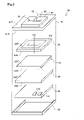
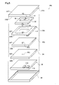
- FIG. 3 is an exploded perspective view showing the internal configuration of the coil unit
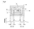
- FIG. 4 is an explanatory diagram showing the shape and arrangement position of the first heat sink in plan view
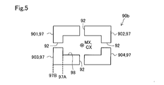
- FIG. 5 is an explanatory diagram showing the shape of the first heat sink in another form 1 of the first embodiment
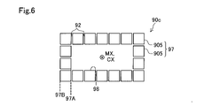
- FIG. 6 is an explanatory diagram showing the shape of the first heat sink in another form 2 of the first embodiment
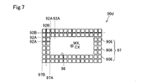
- FIG. 7 is an explanatory diagram showing the shape of the first heat sink in another form 3 of the first embodiment
- FIG. 8 is an exploded perspective view showing the internal configuration of the coil unit of the second embodiment
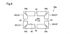
- FIG. 9 is an explanatory diagram showing the configuration of the heat dissipation connection part in another form 1 of the second embodiment
- FIG. 10 is an explanatory diagram showing the configuration of the heat dissipation connection part in another form 2 of the second embodiment
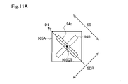
- FIG. 11A is an explanatory diagram showing the shape and arrangement position of the heat dissipation connection
- FIG. 11B is an explanatory diagram showing the configuration of the heat dissipation connection part in another form 3 of the second embodiment
- FIG. 11C is an explanatory diagram showing the shape of the heat dissipation connection part in another form 3 of the second embodiment
- FIG. 12 is an explanatory diagram showing the configuration of the heat dissipation connection part in another form 4 of the second embodiment
- FIG. 13 is an exploded perspective view showing the internal configuration of the coil unit of the third embodiment
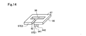
- FIG. 14 is an explanatory diagram showing the configuration of the first heat radiation plate and the heat radiation connection part in another form
- 15A and 15B are explanatory diagrams showing the arrangement positions of the heat dissipation connection portions of another form of the coil unit.
- FIG. 1 shows a contactless power supply system 300 including the coil unit 80 of this embodiment.
- Contactless power supply system 300 includes power transmitter 100 installed on road RS and power receiver 205 mounted on vehicle 200 .
- Contactless power supply system 300 is a system capable of supplying power from power transmitter 100 to power receiver 205 of vehicle 200 in a contactless manner.
- the coil unit 80 is provided in the power transmitter 100 .
- the power transmitter 100 includes a power transmission resonance circuit 110, a power transmission circuit 120, and a power supply circuit .
- the power transmission resonance circuit 110, the power transmission circuit 120, and the power supply circuit 130 are embedded inside the road RS.
- a plurality of power transmission resonance circuits 110 and power transmission circuits 120 may be provided, and for example, they may be arranged continuously along the extending direction of the road RS along which the vehicle 200 travels.
- the power transmission resonance circuit 110, the power transmission circuit 120, and the power supply circuit 130 do not necessarily have to be embedded inside the road RS.
- Power transmission circuit 120 and power supply circuit 130 are preferably provided near power transmission resonance circuit 110 .
- the power supply circuit 130 supplies, for example, AC power from an AC power supply such as a system power supply to the power transmission circuit 120 via a power cable.
- Power transmission circuit 120 is an AC conversion circuit having a rectifier circuit, an inverter circuit, a filter circuit, and the like. Power transmission circuit 120 converts AC power supplied from power supply circuit 130 into DC power, converts the DC power into high-frequency AC power that can be transmitted to power receiver 205 of vehicle 200 , and supplies the high-frequency AC power to power transmission resonance circuit 110 . .
- the power transmission resonance circuit 110 transmits the AC power induced in the power transmission coil 112 to the power reception resonance circuit 210 using the electromagnetic induction phenomenon.
- the power transmission resonance circuit 110 is, as shown in FIG. 2, an LC circuit in which a power transmission coil 112 and a first capacitor 116 functioning as a resonance capacitor are connected in series.
- the power transmission coil 112 and the first capacitor 116 may be connected in parallel.
- the power transmission coil 112 is included in the coil unit 80 of this embodiment.
- power transmitting coil 112 functions as a first coil for transmitting AC power to power receiving coil 212 of vehicle 200 .
- the power receiving coil 212 functions as a second coil.
- the vehicle 200 is, for example, a vehicle equipped with a drive motor such as an electric vehicle or a hybrid vehicle.
- Vehicle 200 includes a power receiver 205 and a battery 230, as shown in FIG.
- the power receiver 205 has a power receiver resonant circuit 210 and a power receiver circuit 220 .
- the power receiving resonance circuit 210 includes, as shown in FIG. 2, a power receiving coil 212 and a second capacitor 216 functioning as a resonance capacitor.
- Power receiving resonance circuit 210 is arranged, for example, on the bottom surface of vehicle 200 .
- the power receiving resonant circuit 210 receives AC power induced in the power transmitting resonant circuit 110 of the power transmitter 100 from the power receiving coil 212 .
- the power receiving circuit 220 converts the AC power output from the power receiving resonance circuit 210 into DC power.
- the power receiving circuit 220 includes, for example, a filter circuit, a rectifier circuit that converts AC power into DC power, and a power conversion circuit that converts the AC power into DC power suitable for charging the battery 230 .
- Battery 230 is, for example, a secondary battery that outputs DC power for driving a drive motor that is a drive source of vehicle 200 .
- the DC power output from power receiving circuit 220 can be used to charge battery 230 .
- the DC power from power receiving circuit 220 may be used to charge an auxiliary battery (not shown) or to drive a drive motor or auxiliary equipment.
- the coil unit 80 includes a substantially rectangular case including an upper surface cover 81 and a lower surface cover 86 provided with a first heat sink 90, a coil substrate 82 including a power transmission coil 112, a ferrite plate 83, a second heat sink 84, A substrate 85 is included.
- FIG. 1 illustrates the coil unit 80 as including the power transmission resonance circuit 110 and the power transmission circuit 120 of the power transmitter 100 for easy understanding of the technology, the coil unit 80 includes at least power transmission It is sufficient that the coil 112, the ferrite plate 83, and the first radiator plate 90 are included.
- Coil unit 80 may include, for example, power transmission resonant circuit 110, power transmission circuit 120, and any other members included in power supply circuit 130.
- the top cover 81 has non-conductivity and is made of a non-magnetic material such as resin.
- the top cover 81 has a substantially flat plate shape.
- Top surface 81T of top cover 81 is a surface of coil unit 80 that faces power receiving coil 212 of vehicle 200 (hereinafter also referred to as a “coil facing surface”).
- the lower surface 81B of the upper surface cover 81 covers the first surface 82T of the coil substrate 82 and protects the coil substrate 82 and the power transmission coil 112 from the outside air.
- the top cover 81 is embedded in the road RS in this embodiment, it may be exposed from the road RS.
- a first radiator plate 90 is provided on the top cover 81 .
- the first radiator plate 90 has a substantially flat plate-like external shape.
- the first radiator plate 90 is provided at a position facing the first surface 82T of the coil substrate 82 .
- “the first heat sink 90 faces the first surface 82T or the second surface 82B” means that the first heat sink 90 faces the first surface 82T or the second surface 82B while being in contact with the first surface 82T or the second surface 82B.
- the first radiator plate 90 is embedded in the top cover 81 by resin molding.
- the first radiator plate 90 is made of a nonmagnetic and highly thermally conductive material, and radiates heat generated in the power transmission coil 112 . From the viewpoint of reducing or preventing magnetic flux interlinking the first heat radiation plate 90, the first heat radiation plate 90 is preferably made of a material with low magnetic permeability.
- the first heat sink 90 is made of metal such as aluminum, an aluminum alloy, or copper, for example.
- the first heat sink 90 may be exposed on the top surface 81T of the top cover 81 .
- the first heat sink 90 may be exposed from the bottom surface 81B of the top cover 81 as long as it is not electrically connected to the power transmission coil 112 .
- the first radiator plate 90 may be attached to the upper surface cover 81 by, for example, welding or bonding with an adhesive, in addition to resin molding.
- the lower surface cover 86 is made of metal such as aluminum, aluminum alloy, or copper, for example.
- metal such as aluminum, aluminum alloy, or copper
- the lower surface cover 86 is made of metal such as aluminum, aluminum alloy, or copper, for example.
- the side surface of the case that accommodates the coil substrate 82, the ferrite plate 83, the second heat sink 84, and the substrate 85 is made of, for example, a metal material such as aluminum, an aluminum alloy, or copper, or a resin material. you can
- the side surfaces of the case may be made of the same material as the top cover 81 and the bottom cover 86, or may be made of a different material. By using a resin material for the side surface of the case, it is possible to reduce or prevent interruption of the magnetic flux generated from the power transmission coil 112 .
- the coil substrate 82 is a rigid type printed wiring board.
- the coil substrate 82 has a substantially rectangular external shape in plan view.
- a power transmission coil 112 is formed inside the coil substrate 82 .
- the power transmission coil 112 is a laminated coil formed by laminating a plurality of annular conductors surrounding the central axis CX.
- the power transmission coil 112 is provided with a hollow region containing no conductor at a position including the central axis CX.
- the power transmission coil 112 is insulated and not electrically connected to the first heat sink 90 .
- the power transmitting coil 112 has a first surface 82T as a coil surface facing the power receiving coil 212 when power is supplied to the power receiving coil 212, and a second surface 82B as a coil surface on the opposite side of the first surface 82T.
- the surface close to the coil facing surface is also called a first surface 82T
- the surface opposite to the first surface 82T of the coil substrate 82 is also called a second surface 82B.
- Power transmission coil 112 is not limited to a form provided on a printed wiring board.
- a conducting wire such as a magnet wire may be used for the power transmission coil 112.
- the power transmission coil 112 may be formed by resin-molding a coiled magnet wire.
- the power transmission coil 112 may be, for example, a spiral coil obtained by cutting a conductor into a spiral shape, or may be various coils such as a helical coil in which a conductor having a circular or rectangular cross section is spirally wound. good.
- the conducting wires may be formed of stranded wires.
- the ferrite plate 83 has a substantially rectangular external shape in plan view.
- the ferrite plate 83 has a coil mounting surface 83T for mounting the coil substrate 82, and a bottom surface 83B located on the back side of the coil mounting surface 83T.
- the coil mounting surface 83T is a surface arranged at a position closer to the coil facing surface than the bottom surface 83B.
- the ferrite plate 83 is arranged such that the coil mounting surface 83T faces the second surface 82B of the coil substrate 82 .
- the ferrite plate 83 may be provided in a state separated from the second surface 82B.
- the ferrite plate 83 may be provided with a through hole for inserting a wiring that electrically connects the power transmission coil 112 and the substrate 85 .
- the second radiator plate 84 has a substantially rectangular external shape in plan view.
- the second radiator plate 84 is made of metal such as aluminum, an aluminum alloy, or copper, for example.
- the second radiator plate 84 has a top surface 84T, which is a surface close to the coil facing surface, and a bottom surface 84B located on the back side of the top surface 84T.
- the second radiator plate 84 is arranged on the opposite side of the coil substrate 82 with the ferrite plate 83 interposed therebetween.
- the second radiator plate 84 is arranged at a position where the top surface 84T faces the bottom surface 83B of the ferrite plate 83 .
- the second radiator plate 84 is provided with the top surface 84T in contact with the bottom surface 83B of the ferrite plate 83 .
- the top surface 84T may be spaced apart from the bottom surface 83B of the ferrite plate 83.
- a cooling device using a coolant or the like may be provided between the ferrite plate 83 and the second radiator plate 84.
- the second radiator plate 84 may be provided with a through-hole for inserting a wiring that electrically connects the power transmission coil 112 and the substrate 85 .
- the substrate 85 is a wiring substrate arranged at a position facing the lower surface 84B of the second heat sink 84 .
- the first capacitor 116 included in the power transmission resonance circuit 110, the capacitor 124 of the filter circuit included in the power transmission circuit 120, and the like are mounted on the substrate 85 .
- the first capacitor 116 may be mounted on the coil substrate 82 .
- the first capacitor 116 and the substrate 85 may be provided outside the case or arranged outside the coil unit 80 .
- FIG. 4 shows the power transmission coil 112 and the first heat radiation plate 90 in plan view from the coil facing surface.
- FIG. 4 schematically shows the power transmission coil 112 and the first radiator plate 90 arranged on the first surface 82T of the power transmission coil 112, and the illustration of other members is omitted.
- the first radiator plate 90 includes a main body portion 97, an opening portion 98, and an insulating portion 92.
- the body portion 97 is a substantially flat plate-shaped member made of a nonmagnetic and highly thermally conductive material, and is a portion that dissipates heat generated in the power transmission coil 112 .
- the body portion 97 has an inner edge 97A surrounding the opening 98 and an outer edge 97B.
- the opening 98 is a through hole provided in the center of the main body 97 in plan view. As shown in FIG. 4 , opening 98 is arranged to include center axis CX of power transmission coil 112 .
- the insulating portion 92 functions as an electrical resistance to reduce or prevent eddy currents from flowing through the body portion 97 .
- an alternating current flows through power transmission coil 112
- magnetic flux is formed around power transmission coil 112 .
- the magnetic flux formed around power transmission coil 112 passes through the hollow portion of power transmission coil 112 , ferrite plate 83 , and the outer peripheral side of power transmission coil 112 .
- alternating current flows through power receiving coil 212 .
- magnetic flux is also formed around power receiving coil 212 .
- the power receiving coil 212 receives electric power from the power transmitting coil 112 in a contactless manner due to the magnetic flux that interlinks both the power transmitting coil 112 and the power receiving coil 212 .
- FIG. 4 schematically shows magnetic flux MX formed in the hollow portion of power transmitting coil 112 when power is supplied to power receiving coil 212 .
- electromagnetic induction when power is supplied from the power transmitting coil 112 to the power receiving coil 212 causes the magnetic flux MX to move in the direction opposite to the magnetic flux MX as indicated by the arrow EC in FIG.
- eddy currents that generate magnetic flux of
- the inductance of the power transmitting coil 112 decreases
- the coupling coefficient between the power transmitting coil 112 and the power receiving coil 212 decreases, and the power loss increases. power supply characteristics can be degraded.
- the cutout formed in the body portion 97 functions as the insulating portion 92 .
- a notch that divides the main body portion 97 from the inner edge 97A to the outer edge 97B functions as the insulating portion 92 .
- the size and shape of the notch can be arbitrarily set to the extent that the eddy current does not flow through the body portion 97 .
- the insulating portion 92 functions as an electrical resistance against eddy currents that may annularly flow in the main body portion 97 along the arrow EC, thereby reducing or preventing the occurrence of eddy currents in the main body portion 97 .
- the insulating portion 92 may be formed of an insulator connecting the inner edge 97A to the outer edge 97B of the main body portion 97 instead of the notch formed in the main body portion 97 .
- FIG. 4 conceptually shows an example of the magnitude of the magnetic flux density of the magnetic flux formed around the power transmitting coil 112 when power is supplied to the power receiving coil 212 .
- an example of the magnitude of the magnetic flux density at the broken line MD position including the central axis CX of the power transmission coil 112 is shown.
- the magnetic flux density increases near the inner peripheral end 112A of the power transmitting coil 112 and near the outer peripheral end 112B of the power transmitting coil 112 .
- the magnetic flux density is reduced at positions directly above the power transmission coil 112 from the inner peripheral end 112A to the outer peripheral end 112B of the power transmission coil 112, because the eddy current that can flow in the power transmission coil 112 itself, which is a conductor, tends to block the magnetic flux density.
- the body portion 97 is arranged at a position overlapping the power transmission coil 112 in plan view. Specifically, in plan view, outer edge 97B and inner edge 97A of main body portion 97 are arranged at positions included between inner peripheral end 112A and outer peripheral end 112B of power transmission coil 112 .
- the first heat sink 90 is arranged at a position directly above the power transmission coil 112 with a low magnetic flux density.
- the power transmission coil 112 is made of a conductor formed on a printed wiring board, eddy current is more likely to occur in the conductor of the power transmission coil 112 than in a coil made of twisted wires. Therefore, the magnetic flux density directly above the power transmission coil 112 can be made smaller. Therefore, the first radiator plate 90 can be arranged at a position where the magnetic flux density is lower.
- the first heat radiation plate 90 is arranged at a position facing the first surface 82T, which is the coil facing surface of the power transmission coil 112 .
- the first heat radiation plate 90 is generated in the first heat radiation plate 90 by the magnetic flux generated by the power transmission coil 112 when AC power is transmitted from the power transmission coil 112 to the power reception coil 212. It has an insulating portion 92 for reducing eddy currents.
- the coil unit 80 of the present embodiment by improving the heat dissipation performance of the power transmission coil 112 and reducing or preventing the generation of eddy current in the first heat radiation plate 90, the power transmission coil 112 to the power reception coil 212 is reduced. It is possible to reduce or prevent deterioration of power supply characteristics to.
- the coil unit 80 of this embodiment includes a top cover 81 for covering and protecting the first surface 82T, which is the surface facing the coil.
- the first heat sink 90 is provided at a position facing the first surface 82T of the top cover 81 . Therefore, the first heat radiation plate 90 absorbs the heat generated in the power transmission coil 112, and radiates heat from the coil facing surface to the space between the power transmission coil 112 and the power reception coil 212, such as the outside of the road RS. can do.
- the first radiator plate 90 includes the opening 98 and the main body 97 surrounding the opening 98 .
- the insulating portion 92 is a notch that divides from an inner edge 97A of the body portion 97 surrounding the opening 98 to an outer edge 97B of the body portion 97 . Therefore, the electrical resistance of the insulating portion 92 can be increased while simplifying the structure of the first heat radiation plate 90 as compared with a configuration in which the first heat radiation plate 90 is provided with an insulator.
- the opening 98 is arranged on the central axis CX of the power transmission coil 112, and the main body 97 is arranged at a position overlapping the power transmission coil 112 in plan view.
- the first radiator plate 90 contains a material with low magnetic permeability. Therefore, the magnetic flux interlinking with the first heat sink 90 can be further reduced or prevented.
- FIG. 5 illustrates the first radiator plate 90b included in the coil unit 80 as another form 1 of the first embodiment.
- the first heat sinks 90b, 90c, and 90d are schematically shown in plan view from the coil-facing surface.
- the shape of the first heat sink 90b is different from that of the first heat sink 90 shown in the first embodiment.
- Other configurations of the coil unit 80 are the same as those of the coil unit 80 of the first embodiment.
- the first radiator plate 90b has four insulating portions 92.
- the main body portion 97 is divided into four regions by providing four insulating portions 92 as notches that divide the inner edge 97A to the outer edge 97B of the first heat sink plate 90b.
- Each main body portion 97 divided by the insulating portion 92 is also called a "main body forming portion".
- the body portion 97 includes body forming portions 901-904.
- the coil unit 80 of the present embodiment four insulating portions 92 are provided, and the first radiator plate 90b is divided into a plurality of body forming portions 901-904. Therefore, by providing a plurality of insulating portions 92, it is possible to further reduce the eddy current flowing along the direction of generating the magnetic flux opposite to the magnetic flux MX in the first radiator plate 90b.
- FIG. 6 illustrates a first radiator plate 90c included in a coil unit 80 as another form 2 of the first embodiment.
- the first heat sink 90c is provided with a larger number of insulating portions 92 than the first heat sink 90b described above.
- 18 insulating portions 92 are provided and 18 body forming portions 905 are provided.
- the number of insulating parts 92 may be one as shown in the first embodiment, or may be any number of two or more.
- each main body forming portion 905 has a substantially square external shape in plan view.
- the shape of the body forming portion 905 can be any shape.
- the main body forming portion 905 preferably has a shape such as a shape in which the distance from the inner edge 97A to the outer edge 97B is small, for example. is preferably a shape that sufficiently reduces or prevents the
- FIG. 7 illustrates a first radiator plate 90d included in a coil unit 80 as another form 3 of the first embodiment.
- the first radiator plate 90d has more insulating portions 92 and body forming portions 906 than the first radiator plate 90c described above.
- two types of cutouts formed in the body portion 97 function as the insulating portion 92 .
- the first notch 92A that divides the inner edge 97A to the outer edge 97B of the first heat sink 90d intersects with the first notch 92A, It has a second notch 92B that divides from one outer edge 97B to the other outer edge 97B.
- the insulating portions 92 may be set in any shape, number, and arrangement, and the body forming portions 906 may be set in any shape, number, and arrangement.
- the coil unit 80b of the second embodiment differs from the coil unit 80 of the first embodiment in that the arrangement position of the first heat sink 90 is different and that a heat dissipation connection portion 94 is further provided. are different.
- the coil unit 80b has a top cover 81b instead of the top cover 81, a coil substrate 82b instead of the coil substrate 82, and a ferrite plate 83b instead of the ferrite plate 83, in the coil unit of the first embodiment. 80 is different.
- Other configurations of the coil unit 80b are the same as those of the coil unit 80 of the first embodiment.
- the first heat sink 90 is provided at a position facing the first surface 82T of the coil substrate 82, as in the first embodiment.
- the first heat sink 90 is embedded in the top cover 81 by resin molding. It is arranged between the substrate 82 .
- the shape and arrangement position of the first heat sink 90 are the same as those of the first heat sink 90 in the first embodiment.
- the top cover 81b is different from the top cover 81 of the first embodiment in that it does not have the first heat sink 90, and the rest of the structure is the same as the top cover 81.
- the first heat radiation plate 90 having the heat radiation connection portion 94 has the upper surface cover 81b, as in the first embodiment, from the viewpoint of facilitating the radiation of the heat of the power transmission coil 112 from the coil facing surface to the outside of the coil unit 80b. You can prepare for
- the coil substrate 82b has a through hole 822 for inserting the heat dissipation connection portion 94.
- Other configurations of the coil substrate 82b are the same as those of the coil substrate 82 in the first embodiment.
- the through hole 822 is provided within the area of the coil substrate 82 where the power transmission coil 112 is arranged.
- An insulator (not shown) is provided around the through-hole 822 to prevent electrical connection between the heat dissipation connection portion 94 and the power transmission coil 112 .
- the through-holes 822 may be arranged at various positions within the region where the power transmission coil 112 is arranged so as to avoid contact with the conductor of the power transmission coil 112 .
- the through hole 822 is formed from the viewpoint of avoiding electrical connection between the heat dissipation connection portion 94 and the power transmission coil 112. 112 conductors.
- the power transmitting coil 112 may have a bent shape to avoid the through hole 822 . Further, for example, when sufficient power transmission efficiency is obtained from the power transmission coil 112 to the power reception coil 212, the through hole 822 may be provided outside the area where the power transmission coil 112 is arranged.
- the ferrite plate 83b has a through-hole 832 for inserting the heat dissipation connection portion 94.
- the position and size of the through hole 832 are preferably set so as not to block the magnetic flux passing through the ferrite plate 83b.
- Other configurations of the ferrite plate 83b are the same as those of the ferrite plate 83 in the first embodiment.
- the heat dissipation connection part 94 is made of a non-magnetic and highly thermally conductive material.
- the heat dissipation connection part 94 is made of the same material as the first heat dissipation plate 90 .
- the heat dissipation connection portion 94 is made of a metal such as aluminum, an aluminum alloy, or copper. From the viewpoint of reducing or preventing the magnetic flux interlinking the heat dissipation connection part 94 and the first heat dissipation plate 90, the heat dissipation connection part 94 is preferably made of a material with low magnetic permeability.
- the heat dissipation connection part 94 and the first heat dissipation plate 90 may be integrally formed in the manufacturing process of the first heat dissipation plate 90, for example.
- the heat dissipation connection part 94 is a substantially cylindrical long member.
- the longitudinal direction of the heat dissipation connection portion 94 matches the stacking direction of the coil substrate 82b, the ferrite plate 83b, and the second heat dissipation plate 84 in the coil unit 80b.
- the heat dissipation connection part 94 connects the first heat dissipation plate 90 and the second heat dissipation plate 84 .
- the heat dissipation connection portion 94 is inserted through the through holes 822 and 832 and connected to the contacts 842 on the upper surface 84T of the second heat dissipation plate 84 .
- the heat dissipation connection part 94 can have any shape that connects the first heat dissipation plate 90 and the second heat dissipation plate 84 .
- the shape of the heat dissipation connection portion 94 may be a polygonal prism such as a square prism or a hexagonal prism, in addition to the cylindrical shape.
- the shape of the heat dissipation connection portion 94 is not limited to a columnar shape, and may be a polyhedron such as a rectangular parallelepiped or a cube, or a plate shape.
- the shape of the heat dissipation connection portion 94 is such that, for example, the heat dissipation connection portion 94 does not pass through the through-holes 822 and 832, bypasses the coil substrate 82b and the ferrite plate 83b from the outside, and passes through the coil substrate 82b and the ferrite plate 83b.
- the first heat sink 90 and the second heat sink 84 may be connected by avoiding contact with 83b.
- the heat dissipation connection part 94 transfers heat between the first heat dissipation plate 90 and the second heat dissipation plate 84 .
- the heat generated in the power transmission coil 112 is absorbed by the first radiator plate 90 .
- the heat of the first heat sink 90 is radiated to the second heat sink 84 via the heat sink connection portion 94 .
- the heat transferred to the second radiator plate 84 is radiated outside the coil unit 80b via the lower surface cover 86 .
- the heat dissipation connection part 94 is set to radiate the heat of the second heat dissipation plate 84 to the first heat dissipation plate 90 . good too.
- the coil unit 80b of the present embodiment further includes the heat radiation connecting portion 94 that connects the first heat radiation plate 90 and the second heat radiation plate 84 together. Therefore, it is possible to increase the number of heat dissipation paths for heat generated in the power transmission coil 112 in the coil unit 80b, and to improve the heat dissipation performance in the coil unit 80b.
- FIG. 9 illustrates a heat dissipation connection portion 94b provided in a coil unit 80b as another form 2 of the second embodiment.
- the first heat sinks 90b, 90c, and 90d are schematically shown in plan view from the coil substrate 82b, unlike FIG. 5 and the like.
- the shape and the like of the first heat radiation plate 90b shown in FIG. 9 are the same as those of the above-described first heat radiation plate 90b, so the description thereof is omitted.
- Other configurations of the coil unit 80b are the same as those of the coil unit 80b of the second embodiment.
- each of the plurality of main body forming portions 901 to 904 is provided with one heat dissipation connection portion 94b.
- the shape of the heat dissipation connection part 94b is a flat plate shape, and the surface direction thereof is arranged along the stacking direction of the coil substrate 82b, the ferrite plate 83b, and the second heat dissipation plate 84 in the coil unit 80b.
- each of the plurality of body forming portions 901 to 904 is provided with the heat dissipation connection portion 94b, so that heat dissipation paths for heat generated in the power transmission coil 112 in the coil unit 80b can be further increased. It is possible to further improve the heat dissipation performance in the coil unit 80b.
- one main body forming portion has one heat dissipation connection portion 94b, so that each of the main body forming portions 901 to 904 is connected to the second heat dissipation plate 84 via the heat dissipation connection portion 94b.
- FIG. 10 shows an example of the heat dissipation connection portion 94c.
- the shape and the like of the first heat sink 90c shown in FIG. 10 are the same as those of the first heat sink 90c described above, so description thereof will be omitted.
- each of the plurality of main body forming portions 905 is provided with one heat dissipation connection portion 94c.
- the shape of each of the heat dissipation connection portions 94c is flat and matched with each other.
- Each of the heat dissipation connection portions 94c has an elongated shape along the stacking direction in the coil unit 80b to the extent that the first heat dissipation plate 90b and the second heat dissipation plate 84 can be connected.
- each of the heat dissipation connection portions 94 c is arranged in such a direction that the plane direction thereof is radial around the central axis CX of the power transmission coil 112 .
- each of the heat dissipation connection portions 94c is parallel to the direction in which the magnetic flux generated from the power transmission coil 112 interlinks with the heat dissipation connection portions 94c.
- the shape of the heat dissipation connection portion 94c is not limited to a flat plate shape, and may be a polygonal prism such as a cube, a cylinder, a quadrangular prism, or a hexagonal prism. good.
- the shapes of the heat dissipation connection portions 94c provided in the plurality of main body forming portions 905 do not necessarily have to match each other, and may be different shapes.
- FIG. 11A shows an enlarged view of one main body forming portion 905A among the plurality of main body forming portions 905 included in the first radiator plate 90c shown in FIG.
- FIG. 11A shows the direction D1 of the magnetic flux generated on the second surface 82B side of the power transmission coil 112 among the magnetic fluxes generated around the power transmission coil 112 when power is supplied from the power transmission coil 112 to the power reception coil 212, and the plate-shaped heat dissipation device.
- a surface direction SD of the connecting portion 94c is conceptually shown.
- a heat dissipation connection portion 94R as a comparative example is further indicated by a dashed line.
- the heat dissipation connection portion 94R is arranged such that its planar direction SDR is perpendicular to the magnetic flux direction D1.
- Heat dissipation connection portion 94 ⁇ /b>R can block the magnetic flux generated from power transmission coil 112 because its surface direction is perpendicular to direction D ⁇ b>1 of the magnetic flux. Therefore, the heat dissipation connection portion 94R may reduce power transmission performance from the power transmission coil 112 to the power reception coil 212 .
- each of the plurality of heat dissipation connection portions 94c is arranged so that the surface direction SD of the heat dissipation connection portion 94c and the direction D1 of the magnetic flux are parallel to each other.
- 94R it is possible to reduce or suppress blocking of the magnetic flux generated by the power transmission coil 112 by the first radiator plate 90c. Therefore, according to the coil unit 80b of the present embodiment, it is possible to reduce or prevent deterioration of power transmission performance from the power transmitting coil 112 to the power receiving coil 212.
- the center 905CT of the body forming portion 905 is shown in FIG. 11A.
- the center 905CT means the center of the shape of the main body forming portion 905 in plan view.
- the center 905CT may be set at the center of gravity of the shape of the body forming portion 905, for example.
- the heat dissipation connection portion 94c is arranged in the center of each of the plurality of main body forming portions 905. As shown in FIG. Therefore, the heat radiation connecting portion 94c can efficiently absorb the heat of the main body forming portion 905, and can reduce or prevent variations in heat in the main body forming portion 905.
- the heat radiation connecting portion 94c is not limited to the center of the main body forming portion 905, and may be arranged at a position where the heat of the main body forming portion 905 can be efficiently absorbed in light of the shape of the main body forming portion 905 and the like.
- FIG. 11B Alternative form 3 of the second embodiment: 11B and 11C, a heat dissipation connection portion 940 provided in a coil unit 80b as another form 3 of the second embodiment will be described.
- the heat dissipation connection portion 940 is different in shape from the heat dissipation connection portion 94 exemplified in the second embodiment, and the rest of the configuration is the same as the heat dissipation connection portion 94 .
- the heat dissipation connection portion 940 includes a first connection portion 943 , a second connection portion 946 and an intermediate connection portion 944 .
- the through hole 822 provided in the coil substrate 82b has a shape corresponding to the shape of the first connection portion 943
- the through hole 832 provided in the ferrite plate 83b has a shape corresponding to the shape of the second connection portion 946. It has a shape corresponding to the shape.
- the heat dissipation connection portion 940 is formed by connecting a first connection portion 943, a second connection portion 946, and an intermediate connection portion 944 to each other.
- the first connection portion 943, the second connection portion 946, and the intermediate connection portion 944 may be connected, for example, by welding, and are made of a metal with high thermal conductivity such as copper or aluminum, or a heat conductive material such as alumina or aluminum nitride.
- the connection may be made by adhesion using an adhesive or the like to which ceramics with a high modulus is added as a filler.
- the heat dissipation connection portion 940 may be integrally formed by molding or the like.
- the shape of each portion of the first connection portion 943, the second connection portion 946, and the intermediate connection portion 944 may be changed by cutting a metal. may be formed.
- the first connection portion 943 is a portion of the heat radiation connection portion 940 that is arranged in the through hole 822 of the coil substrate 82b.
- the first connection portion 943 has a substantially flat plate-like external shape.
- the first connection portion 943 is arranged in a region of the coil substrate 82 where the power transmission coil 112 is arranged.
- the cross section perpendicular to the winding direction of the conductor in the power transmission coil 112 that is, the width direction of the conductor of the power transmission coil 112 becomes smaller by the cross-sectional integral of the first connection portion 943, and the electrical resistance of the power transmission coil 112 may increase.
- first connection portion 943 is arranged in the through hole 822 such that the plane direction thereof is parallel to the winding direction of the power transmission coil 112 .
- first connection portion 943 is arranged such that the cross-sectional area of first connection portion 943 corresponding to the width direction of power transmission coil 112 is the smallest in the region where power transmission coil 112 is arranged.
- the second connection portion 946 is a portion of the heat dissipation connection portion 940 that is arranged in the through hole 832 of the ferrite plate 83b.
- the second connection portion 946 has a substantially flat plate-like external shape.
- the second connection portion 946 is arranged such that its surface direction is parallel to the direction of the magnetic flux generated around the power transmission coil 112 . By configuring in this way, it is possible to reduce or suppress blocking of the magnetic flux generated by the power transmission coil 112 by the second connection portion 946 .
- the intermediate connection portion 944 is a member having a substantially flat plate-like external shape.
- the intermediate connection portion 944 is arranged between the coil substrate 82b and the ferrite plate 83b so that the plane direction thereof is parallel to the plane directions of the coil substrate 82b and the ferrite plate 83b.
- the intermediate connection portion 944 is used to connect the first connection portion 943 and the second connection portion 946 .
- the intermediate connection portion 944 may be omitted.
- the heat dissipation connection portion 940 provided in the coil unit 80b of the present embodiment has a shape in which the surface direction thereof is parallel to the winding direction of the power transmission coil 112 in the through hole 822, and In the through hole 832 of the ferrite plate 83b, the plane direction and the magnetic flux direction are parallel to each other.
- the coil unit 80b of this form while obtaining the heat dissipation performance of the heat dissipation connection part 940, it is possible to reduce or prevent an increase in the electrical resistance of the power transmission coil 112 at the position where the heat dissipation connection part 940 is arranged, It is possible to reduce or prevent the magnetic flux generated around the coil 112 from being cut off by the heat dissipation connection portion 940, and reduce or prevent a decrease in the efficiency of power transmission from the power transmitting coil 112 to the power receiving coil 212. .
- FIG. 12 illustrates a heat dissipation connection portion 94d provided in a coil unit 80b as another form 4 of the second embodiment.
- the configuration of the first heat sink 90d shown in FIG. 12 is the same as that of the first heat sink 90d described above, so description thereof will be omitted.
- each of the plurality of first heat radiation plates 90d is provided with a heat radiation connection portion 94d.
- the heat dissipation connection portion 94d is arranged in the center of each of the first heat dissipation plates 90d.
- the heat dissipation connection portion 94d may be provided for each first heat dissipation plate 90d, or may be provided only for one main body forming portion 906 out of the plurality of main body forming portions 906. FIG. In this manner, the shape, number, and arrangement of the heat dissipation connection portions 94d may be arbitrarily set according to the shape, number, and arrangement of the first heat dissipation plate 90d.
- the coil unit 80c of the third embodiment includes a first heat sink 90e instead of the first heat sink 90, and a ferrite plate 83c instead of the ferrite plate 83, It differs from the coil unit 80 of the first embodiment.
- Other configurations of the coil unit 80c are the same as those of the coil unit 80 of the first embodiment.
- the ferrite plate 83c is different from the ferrite plate 83 of the first embodiment in that it includes a first heat sink 90e, and is otherwise the same as the ferrite plate 83 of the first embodiment.
- the first heat sink 90 is embedded in the top cover 81 by resin molding.
- the present embodiment differs from the first embodiment in that the first heat radiation plate 90e is provided on the ferrite plate 83c. Further, in the first embodiment, an example in which the first heat radiation plate 90 is provided at a position facing the first surface 82T of the coil substrate 82 is shown. On the other hand, in this embodiment, as shown in FIG. 13, the first heat sink 90e is provided at a position facing the second surface 82B of the coil substrate 82, which is different from the first embodiment. do.
- the body portion 97 of the first heat radiation plate 90e includes four body forming portions 907.
- Each of the body forming portions 907 is fitted in a through hole of the ferrite plate 83c, and is arranged from the coil mounting surface 83T of the ferrite plate 83c to the bottom surface 83B.
- the main body forming portion 907 is in contact with the second heat sink 84 at a contact point 843 on the upper surface 84T of the second heat sink 84 . Thereby, the main body forming portion 907 transfers the heat generated in the power transmission coil 112 to the second heat radiation plate 84 .
- the heat of the second radiator plate 84 is radiated to the outside through the lower surface cover 86 .
- the four main body forming portions 907 are arranged apart from each other.
- the body forming portions 907 are separated from each other, so that the ferrite plate 83c between the body forming portions 907 functions as the insulating portion 92 .
- the main body forming portion 907 is set to have a size and an arrangement that can avoid interruption of the magnetic flux generated by the power transmission coil 112 and passing through the ferrite plate 83c.
- each of the main body forming portions 907 is arranged at a position overlapping the power transmission coil 112 in plan view. It is preferable that the main body forming portion 907 have a shape along the direction of the magnetic flux generated from the power transmission coil 112 .
- the plurality of main body forming portions 907 of the first radiator plate 90e are provided at positions facing the bottom surface 83B of the ferrite plate 83c. Therefore, the heat generated from the power transmission coil 112 can be directly radiated to the second radiator plate 84, and the heat radiation performance to the opposite side of the coil facing surface of the coil unit 80c can be improved.
- the plurality of heat dissipation connection portions 94 be arranged at positions close to each other. By arranging in this way, while the heat radiation performance of the coil unit 80b is improved by the plurality of heat radiation connecting portions 94, the magnetic flux generated in the power transmission coil 112 when power is supplied between the power transmission coil 112 and the power reception coil 212 heats the first heat radiation plate 90. eddy currents that can occur in
- FIG. 14 shows an example in which the first heat radiation plate 90 has two heat radiation connection portions 941 and 942, namely a first heat radiation connection portion 941 and a second heat radiation connection portion 942 .
- FIG. 14 shows an end portion 97E1 of the body portion 97 facing the insulating portion 92, which is a notch, and an end portion 97E2 opposite to the end portion 97E1 with the insulating portion 92 interposed therebetween.
- the first heat dissipation connection portion 941 and the second heat dissipation connection portion 942 are arranged so as to be close to each other at the end portion 97E1 of the body portion 97 .
- the closed circuit formed by the first heat dissipation plate 90, the second heat dissipation plate 84, and the heat dissipation connection portion 94 can be formed while improving the heat dissipation performance of the first heat dissipation plate 90 by the plurality of heat dissipation connection portions 941 and 942. It is possible to reduce the eddy current that can be generated in the first heat radiation plate 90 .
- the first heat sink 90 is provided at a position facing the first surface 82T of the coil substrate 82
- the first heat sink 90e is a ferrite plate.
- An example provided in 83c is shown.
- the first radiator plate 90 may be provided between the second surface 82B of the coil substrate 82 and the coil mounting surface 83T of the ferrite plate 83b.
- the configuration of the coil unit 80d shown in FIG. 15 differs from the configuration of the coil unit 80b of the second embodiment in that the arrangement position of the first heat sink 90, the shape of the through hole 832, and the shape of the through hole 822 are different. is not provided, and the rest of the configuration is the same as the coil unit 80b of the second embodiment.
- the through hole 832 has a shape corresponding to the shape of the heat dissipation connection portion 94c.
- the first radiator plate 90 is arranged at a position facing the second surface 82B of the coil substrate 82 .
- the main body portion 97 of the first heat sink 90 is arranged at a position overlapping the power transmission coil 112 in plan view.
- the first radiator plate 90 is arranged at a position directly below the power transmission coil 112 having a low magnetic flux density.
- the first heat radiation plate 90 can be arranged at a position where the magnetic flux density is lower even at the position facing the second surface 82B of the coil substrate 82 .
- the first heat dissipation plate 90 has a heat dissipation connection portion 94c.
- the heat dissipation connection portion 94c has the same shape as the heat dissipation connection portion 94c described above, and is arranged in the through hole 832 of the ferrite plate 83b such that the surface direction thereof is parallel to the direction of the magnetic flux generated from the power transmission coil 112. are placed in By configuring in this way, it is possible to reduce or prevent the magnetic flux generated from the power transmission coil 112 from being cut off by the heat dissipation connection portion 94c.
- the first radiator plate 90 is provided between the second surface 82B of the coil substrate 82 and the coil mounting surface 83T of the ferrite plate 83b. Therefore, the heat generated from the coil substrate 82 can be easily transferred to the second radiator plate 84, and the heat radiation performance to the opposite side of the coil facing surface of the coil unit 80d can be improved.
Landscapes
- Engineering & Computer Science (AREA)
- Power Engineering (AREA)
- Mechanical Engineering (AREA)
- Transportation (AREA)
- Computer Networks & Wireless Communication (AREA)
- Transformer Cooling (AREA)
- Charge And Discharge Circuits For Batteries Or The Like (AREA)
- Current-Collector Devices For Electrically Propelled Vehicles (AREA)
- Electric Propulsion And Braking For Vehicles (AREA)
- Coils Of Transformers For General Uses (AREA)
- Coils Or Transformers For Communication (AREA)
Abstract
コイルユニット(80)は、コイル載置面(83T)と、コイル載置面(83T)の裏側に位置する底面(83B)とを有するフェライト板(83)と、交流電力を送電または受電するための第一コイル(112)であって、第一コイル(112)とは異なる第二コイル(212)と対向させるための第一面(82T)と、第一面の反対側に位置し、コイル載置面(83T)と対向する位置に配置される第二面(82B)とを備える第一コイル(112)と、第一面(82T)または第二面(82B)と対向する位置に配置される第一放熱板(90)であって、交流電力の送電または受電の際に第一コイル(112)が発生させる磁束によって第一放熱板(90)に発生する渦電流を低減するための絶縁部(92)を有する第一放熱板(90)と、を備える。
Description
本出願は、2021年3月10日に出願された日本出願番号2021-038273号に基づくもので、ここにその記載内容を援用する。
本開示は、コイルユニットに関する。
フェライト板のコイル載置面側にコイルを配置し、フェライト板のコイル載置面とは反対側に位置する背面側に、コイル放熱用の金属板を備えるコイルユニットが知られている(例えば、特開2019-9161号公報)。
コイルユニットでは、コイルの温度上昇がコイルの送受電の性能に影響を与えることから、コイルの放熱性能をさらに向上させたいといった要望がある。
本開示は、上述の課題の少なくとも一部を解決するためになされたものであり、以下の形態又は適用例として実現することが可能である。
本開示の一形態によれば、コイルユニットが提供される。このコイルユニットは、コイル載置面と、前記コイル載置面の裏側に位置する底面とを有するフェライト板と、交流電力を送電または受電するための第一コイルであって、前記第一コイルとは異なる第二コイルと対向させるための第一面と、前記第一面の反対側に位置し、前記コイル載置面と対向する位置に配置される第二面とを備える第一コイルと、前記第一面または前記第二面と対向する位置に配置される第一放熱板であって、前記交流電力の送電または受電の際に前記第一コイルが発生させる磁束によって前記第一放熱板に発生する渦電流を低減するための絶縁部を有する第一放熱板と、を備える。
この形態のコイルユニットによれば、第二コイルと対向する第一コイルの第一面、または第一面の反対側に位置する第二面に、渦電流の発生を低減する絶縁部を有する第一放熱板を配置することができる。したがって、第一放熱板での渦電流の発生を低減または防止しつつ、第一コイルの放熱性能を向上させることができる。
本開示についての上記目的およびその他の目的、特徴や利点は、添付の図面を参照しながら下記の詳細な記述により、より明確になる。その図面は、
図1は、非接触給電システムの構成を示す説明図であり、
図2は、非接触給電システムの回路構成を示す説明図であり、
図3は、コイルユニットの内部構成を示す分解斜視図であり、
図4は、第一放熱板の形状および配置位置を平面視で示す説明図であり、
図5は、第1実施形態の他の形態1での第一放熱板の形状を示す説明図であり、
図6は、第1実施形態の他の形態2での第一放熱板の形状を示す説明図であり、
図7は、第1実施形態の他の形態3での第一放熱板の形状を示す説明図であり、
図8は、第2実施形態のコイルユニットの内部構成を示す分解斜視図であり、
図9は、第2実施形態の他の形態1での放熱接続部の構成を示す説明図であり、
図10は、第2実施形態の他の形態2での放熱接続部の構成を示す説明図であり、
図11Aは、放熱接続部の形状および配置位置を示す説明図であり、
図11Bは、第2実施形態の他の形態3での放熱接続部の構成を示す説明図であり、
図11Cは、第2実施形態の他の形態3での放熱接続部の形状を示す説明図であり、
図12は、第2実施形態の他の形態4での放熱接続部の構成を示す説明図であり、
図13は、第3実施形態のコイルユニットの内部構成を示す分解斜視図であり、
図14は、他の形態での第一放熱板および放熱接続部の構成を示す説明図であり、
図15は、他の形態のコイルユニットが有する放熱接続部の配置位置を示す説明図である。
A1.第1実施形態:
図1および図2を用いて本実施形態のコイルユニット80の構成について説明する。図1には、本実施形態のコイルユニット80を備える非接触給電システム300が示されている。非接触給電システム300は、道路RSに設置される送電器100と、車両200に搭載される受電器205とを含んでいる。非接触給電システム300は、送電器100から非接触で車両200の受電器205に電力を供給することが可能なシステムである。本実施形態では、コイルユニット80は、送電器100に備えられている。
図1および図2を用いて本実施形態のコイルユニット80の構成について説明する。図1には、本実施形態のコイルユニット80を備える非接触給電システム300が示されている。非接触給電システム300は、道路RSに設置される送電器100と、車両200に搭載される受電器205とを含んでいる。非接触給電システム300は、送電器100から非接触で車両200の受電器205に電力を供給することが可能なシステムである。本実施形態では、コイルユニット80は、送電器100に備えられている。
送電器100は、送電共振回路110と、送電回路120と、電源回路130とを備えている。本実施形態では、送電共振回路110と、送電回路120と、電源回路130とは、道路RSの内部に埋設されている。送電共振回路110および送電回路120は、複数を備えてよく、例えば、車両200の進行方向となる道路RSの延在方向に沿って連続的に配列して備えられてよい。送電共振回路110、送電回路120、ならびに電源回路130は、必ずしも道路RS内部に埋設される必要はなく、例えば、道路RS上において、車両200の走行の弊害とならない位置に備えられてよい。送電回路120および電源回路130は、送電共振回路110近傍に備えられることが好ましい。
電源回路130は、例えば、系統電源などの交流電源からの交流電力を、電源ケーブルを介して送電回路120に供給する。送電回路120は、整流回路、インバータ回路、ならびにフィルタ回路などを有する交流変換回路である。送電回路120は、電源回路130から供給される交流電力を直流電力に変換し、直流電力を車両200の受電器205へ送電可能な高周波の交流電力に変換して、送電共振回路110に供給する。
送電共振回路110は、電磁誘導現象を利用して送電コイル112に誘導された交流電力を受電共振回路210に送電する。送電共振回路110は、図2に示すように、送電コイル112と、共振コンデンサとして機能する第一コンデンサ116とが直列に接続されているLC回路である。送電コイル112と、第一コンデンサ116とは、並列に接続されていてもよい。
送電コイル112は、本実施形態のコイルユニット80に含まれている。本実施形態では、送電コイル112は、車両200の受電コイル212に、交流電力を送電するための第一コイルとして機能する。本実施形態では、受電コイル212は、第二コイルとして機能する。
車両200は、例えば、電気自動車やハイブリッド車等の駆動モータを搭載する車両で構成される。車両200は、図1に示すように、受電器205と、バッテリ230とを備えている。受電器205は、受電共振回路210と、受電回路220とを有している。
受電共振回路210は、図2に示すように、受電コイル212と、共振コンデンサとして機能する第二コンデンサ216とを含んでいる。受電共振回路210は、例えば、車両200の底面に配置されている。受電共振回路210は、送電器100の送電共振回路110に誘導された交流電力を受電コイル212から受電する。
受電回路220は、受電共振回路210から出力される交流電力を直流電力に変換する。受電回路220は、例えば、フィルタ回路と、交流電力を直流電力に変換する整流回路と、バッテリ230の充電に適した直流電力に変換する電力変換回路とを有している。バッテリ230は、例えば、車両200の駆動源である駆動モータを駆動するための直流電力を出力する二次電池である。受電回路220から出力される直流電力は、バッテリ230の充電に利用することができる。受電回路220からの直流電力は、図示しない補機バッテリの充電や、駆動モータや補機の駆動に利用されてよい。
図3を用いて、本実施形態のコイルユニット80の詳細について説明する。コイルユニット80は、第一放熱板90を備える上面カバー81および下面カバー86を含む略矩形状のケースと、送電コイル112を備えるコイル基板82と、フェライト板83と、第二放熱板84と、基板85とを含んでいる。なお、図1では、技術の理解を容易にするために、コイルユニット80は、送電器100の送電共振回路110および送電回路120を含むように図示されているが、コイルユニット80は、少なくとも送電コイル112、フェライト板83、第一放熱板90を含んでいればよい。コイルユニット80には、例えば、送電共振回路110、送電回路120、ならびに電源回路130に含まれるそれ以外の任意の部材が含まれてよい。
上面カバー81は、非導電性を有し、例えば、樹脂などの非磁性体によって形成されている。上面カバー81は、略平板形状を有している。上面カバー81の上面81Tは、コイルユニット80が有する面のうち、車両200の受電コイル212と対向する面(以下、「コイル対向面」とも呼ぶ。)である。上面カバー81の下面81Bは、コイル基板82の第一面82Tを覆っており、コイル基板82および送電コイル112を外気などから保護している。本実施形態では、上面カバー81は、道路RSに埋設されているが、道路RSから露出されていてもよい。上面カバー81には、第一放熱板90が備えられている。
第一放熱板90は、略平板状の外観形状を有している。第一放熱板90は、コイル基板82の第一面82Tと対向する位置に備えられている。本開示において、「第一放熱板90が第一面82Tまたは第二面82Bと対向する」とは、第一放熱板90が第一面82Tまたは第二面82Bと当接した状態で対向する状態、第一放熱板90が第一面82Tまたは第二面82Bから離間した状態で第一面82Tまたは第二面82Bと対向する状態、ならびに第一放熱板90と、第一面82Tまたは第二面82Bとの間に、第一放熱板90およびコイル基板82とは異なる部材が存在した状態で第一放熱板90が第一面82Tまたは第二面82Bと対向する状態を含む。本実施形態では、第一放熱板90は、樹脂モールドによって上面カバー81内に埋め込まれている。第一放熱板90は、非磁性かつ熱伝導性の高い材料で形成されており、送電コイル112に発生する熱を放熱する。第一放熱板90は、第一放熱板90を鎖交する磁束を低減または防止する観点から、透磁率が小さい材料であることが好ましい。第一放熱板90は、例えば、アルミニウム、アルミニウム合金、銅などの金属によって形成される。第一放熱板90は、上面カバー81の上面81Tで露出されていてもよい。第一放熱板90は、送電コイル112と電気的に接続されない限りにおいて、上面カバー81の下面81Bから露出されていてもよい。第一放熱板90は、樹脂モールドのほか、例えば溶接や接着剤による接着により上面カバー81に取り付けられてもよい。
下面カバー86は、例えば、アルミニウムやアルミニウム合金、銅などの金属によって形成されている。上面カバー81と、下面カバー86とが図示しない固定具によって嵌合することによって、コイル基板82と、フェライト板83と、第二放熱板84と、基板85とを収容するケースが形成される。ケース内には、下面カバー86から上面カバー81に向かって、基板85、第二放熱板84、フェライト板83、ならびにコイル基板82がこの順に積層されて備えられている。下面カバー86は、金属には限定されず、例えば、樹脂材料などであってよく、非磁性材で形成されていてもよい。なお、コイル基板82と、フェライト板83と、第二放熱板84と、基板85とを収容するケースの側面は、例えば、アルミニウムやアルミニウム合金、銅などの金属材料や、樹脂材料などで形成されてよい。ケースの側面は、上面カバー81や下面カバー86と同じ材料で形成されていてもよく、異なる材料で形成されていてもよい。ケースの側面を樹脂材料とすることにより、送電コイル112から発生する磁束が遮断されることを低減または防止することができる。
コイル基板82は、リジッドタイプのプリント配線板である。コイル基板82は、平面視で略矩形の外観形状を有している。コイル基板82の内部には、送電コイル112が形成されている。本実施形態では、送電コイル112は、中心軸CXの周囲を取り囲む環状の導体を複数積層して形成される積層コイルである。送電コイル112には、中心軸CXを含む位置に、導体を含まない中空領域が備えられている。送電コイル112は、第一放熱板90とは絶縁されており、電気的に接続されていない。
送電コイル112は、受電コイル212への給電時に受電コイル212と対向するコイル面としての第一面82Tと、第一面82Tの反対側のコイル面としての第二面82Bとを備えている。本開示では、コイル基板82においても、送電コイル112と同様に、コイル対向面に近い面を第一面82Tとも呼び、コイル基板82の第一面82Tの反対側の面を第二面82Bとも呼ぶことがある。送電コイル112は、プリント配線板に備えられる形態には限定されない。送電コイル112には、例えば、マグネットワイヤなどの導線が用いられてよく、この場合には、送電コイル112は、コイル状に巻き回されたマグネットワイヤが樹脂モールドされることによって形成されてもよい。送電コイル112は、例えば、導体を渦巻き状に切り出したスパイラルコイルであってもよく、横断面形状が円形や角形の導体がらせん状に巻き回されたヘリカルコイルなどの種々のコイルであってもよい。送電コイル112に導線が用いられる場合には、導線は、撚り線で形成されてもよい。
フェライト板83は、平面視で略矩形状の外観形状を有している。フェライト板83は、コイル基板82を載置するためのコイル載置面83Tと、コイル載置面83Tの裏側に位置する底面83Bとを備えている。コイル載置面83Tは、底面83Bよりもコイル対向面に近い位置に配置される面である。フェライト板83は、コイル載置面83Tがコイル基板82の第二面82Bと対向する状態で配置されている。本実施形態では、フェライト板83は、第二面82Bと当接する状態で備えられているが、フェライト板83は、第二面82Bから離間した状態で備えられていてもよい。フェライト板83には、送電コイル112と、基板85とを電気的に接続する配線を挿通するための貫通孔が設けられていてもよい。
第二放熱板84は、平面視で略矩形状の外観形状を有している。第二放熱板84は、例えば、アルミニウムやアルミニウム合金、銅などの金属によって形成されている。第二放熱板84は、コイル対向面に近い面である上面84Tと、上面84Tの裏側に位置する下面84Bとを有する。第二放熱板84は、フェライト板83を挟んだコイル基板82の逆側に配置されている。第二放熱板84は、上面84Tがフェライト板83の底面83Bと対向する位置に配置されている。本実施形態では、第二放熱板84は、上面84Tがフェライト板83の底面83Bと当接する状態で備えられている。上面84Tは、フェライト板83の底面83Bから離間されていてもよく、例えば、フェライト板83と、第二放熱板84との間に、冷媒などを利用した冷却装置が備えられてもよい。第二放熱板84には、送電コイル112と、基板85とを電気的に接続する配線を挿通するための貫通孔が設けられていてもよい。
基板85は、第二放熱板84の下面84Bと対向する位置に配置されている配線基板である。基板85には、例えば、送電共振回路110に含まれる第一コンデンサ116や、送電回路120に含まれるフィルタ回路のキャパシタ124などが搭載されている。なお、第一コンデンサ116は、コイル基板82に搭載されてもよい。第一コンデンサ116や基板85は、ケース外に備えられてよく、コイルユニット80外に配置されてもよい。
図4を用いて、第一放熱板90の形状について説明する。図4の上段には、送電コイル112と、第一放熱板90とが、コイル対向面からの平面視により示されている。図4には、送電コイル112と、送電コイル112の第一面82T上に配置される第一放熱板90とが模式的に示され、それ以外の部材の図示は省略されている。
図4に示すように、第一放熱板90は、本体部97と、開口部98と、絶縁部92と、を備えている。本体部97は、非磁性かつ熱伝導性の高い材料で形成される略平板状の部材であり、送電コイル112に発生する熱を放熱する部分である。本体部97は、開口部98を囲む内縁97Aと、外縁97Bとを有している。開口部98は、本体部97の平面視での中央に備えられている貫通孔である。図4に示すように、開口部98は、送電コイル112の中心軸CXを含むように配置されている。
図4を用いて、絶縁部92の機能の詳細について説明する。絶縁部92は、渦電流が本体部97に流れることを低減または防止するための電気抵抗として機能する。ここで、送電コイル112に交流電流が流れると、送電コイル112の周囲に磁束が形成される。送電コイル112の周囲に形成される磁束は、送電コイル112の中空部と、フェライト板83と、送電コイル112の外周側とを通る。送電コイル112の周囲に形成される磁束の一部が受電コイル212と鎖交すると、受電コイル212に交流電流が流れる。受電コイル212内に交流電流が流れると、受電コイル212周囲にも磁束が形成される。送電コイル112と、受電コイル212とのいずれにも鎖交する磁束によって、受電コイル212が送電コイル112から非接触で電力を受電する。
図4には、受電コイル212への給電時において送電コイル112の中空部に形成される磁束MXが模式的に示されている。ここで、送電コイル112上に導電体が配置される場合には、送電コイル112から受電コイル212への給電時の電磁誘導によって、図4に矢印ECで示すように、磁束MXとは逆向きの磁束を発生させる渦電流が発生することがある。渦電流が発生する場合には、例えば、送電コイル112のインダクタンスの低下、送電コイル112と受電コイル212との結合係数の低下、電力損失の増加などが発生し、送電コイル112から受電コイル212への給電特性が低下し得る。
本実施形態では、本体部97に形成される切欠きが絶縁部92として機能する。具体的には、図4に示すように、本体部97の内縁97Aから外縁97Bまでを分断する切欠きが絶縁部92として機能する。切欠きの大きさや形状は、渦電流が本体部97に流れない程度に、任意に設定することができる。これにより、絶縁部92は、矢印ECに沿って本体部97に環状に流れ得る渦電流に対する電気抵抗として機能し、本体部97に渦電流が発生することを低減または防止している。絶縁部92は、本体部97に形成される切欠きに代えて、本体部97の内縁97Aから外縁97Bまでを繋ぐ絶縁体で形成されてもよい。
図4を用いて、第一放熱板90の配置位置の詳細について説明する。図4の下部には、受電コイル212への給電時に、送電コイル112の周囲に形成される磁束の磁束密度の大きさの一例が概念的に示されている。具体的には、送電コイル112の中心軸CXを含む破線MD位置における磁束密度の大きさの一例が示されている。磁束密度は、送電コイル112の内周端112A近傍と、送電コイル112の外周端112B近傍とで大きくなる。磁束密度は、送電コイル112の内周端112Aから外周端112Bまでの送電コイル112の直上となる位置では、導体である送電コイル112自体に流れ得る渦電流によって遮断されやすいことから、小さくなる。本実施形態では、本体部97は、平面視で送電コイル112と重なる位置に配置されている。具体的には、平面視において、本体部97の外縁97Bおよび内縁97Aが、送電コイル112における内周端112Aから外周端112Bまでの間に含まれる位置に配置されている。この結果、第一放熱板90は、磁束密度の小さい送電コイル112の直上となる位置に配置される。
本実施形態では、送電コイル112は、プリント配線板に形成される導体で形成されているため、撚り線で形成されるコイルに比較して送電コイル112の導体に渦電流が発生しやすい。そのため、送電コイル112直上の磁束密度をより小さくすることができる。したがって、磁束密度がより低い位置に第一放熱板90を配置することができる。
以上、説明したように、本実施形態のコイルユニット80では、第一放熱板90が、送電コイル112のコイル対向面である第一面82Tと対向する位置に配置されている。送電コイル112のコイル対向面に第一放熱板90を備えることにより、コイルユニット80での送電コイル112の放熱性能を向上させることができる。また、本実施形態のコイルユニット80では、第一放熱板90は、送電コイル112から受電コイル212へ交流電力が送電される際に、送電コイル112が発生させる磁束によって第一放熱板90に発生する渦電流を低減するための絶縁部92を有している。そのため、第一放熱板90での渦電流の発生を低減または防止することができる。したがって、本実施形態のコイルユニット80によれば、送電コイル112の放熱性能を向上させるとともに、第一放熱板90での渦電流の発生を低減または防止することにより、送電コイル112から受電コイル212への給電特性が低下することを低減または防止することができる。
本実施形態のコイルユニット80は、コイル対向面となる第一面82Tを覆い、第一面82Tを保護するための上面カバー81を備えている。第一放熱板90は、上面カバー81における第一面82Tと対向する位置に備えられる。したがって、第一放熱板90は、送電コイル112に発生した熱を吸熱し、例えば、道路RSなどの外部などのように、送電コイル112と受電コイル212との間の空間にコイル対向面から放熱することができる。
本実施形態のコイルユニット80によれば、第一放熱板90は、開口部98と、開口部98を囲む本体部97と、を備えている。絶縁部92は、開口部98を囲む本体部97の内縁97Aから本体部97の外縁97Bまでを分断する切欠きである。したがって、第一放熱板90に絶縁体を備える形態に比較して第一放熱板90を簡易な構成にしつつ、絶縁部92の電気抵抗を大きくすることができる。
本実施形態のコイルユニット80によれば、開口部98は、送電コイル112の中心軸CX上に配置され、本体部97は、平面視で送電コイル112と重なる位置に配置される。第一放熱板90を、磁束密度の小さい送電コイル112の直上となる位置に配置することにより、送電コイル112から発生する磁束が第一放熱板90に鎖交することを低減し、渦電流の発生をより低減または防止することができる。
本実施形態のコイルユニット80によれば、第一放熱板90は、透磁率が小さい材料を含んでいる。したがって、第一放熱板90に鎖交する磁束をより低減または防止することができる。
A2.第1実施形態の他の形態1:
図5には、第1実施形態の他の形態1としてのコイルユニット80が備える第一放熱板90bが例示されている。図5から図7において、第一放熱板90b,90c,90dは、コイル対向面からの平面視により模式的に示されている。本実施形態のコイルユニット80では、第一放熱板90bの形状が、第1実施形態で示す第一放熱板90とは異なる。コイルユニット80のそれ以外の構成は第1実施形態のコイルユニット80と同様である。
図5には、第1実施形態の他の形態1としてのコイルユニット80が備える第一放熱板90bが例示されている。図5から図7において、第一放熱板90b,90c,90dは、コイル対向面からの平面視により模式的に示されている。本実施形態のコイルユニット80では、第一放熱板90bの形状が、第1実施形態で示す第一放熱板90とは異なる。コイルユニット80のそれ以外の構成は第1実施形態のコイルユニット80と同様である。
上記第1実施形態で示す第一放熱板90では、1つの絶縁部92を備える例を示した。これに対して、本実施形態では、図5に示すように、第一放熱板90bは4つの絶縁部92を備えている。第一放熱板90bの内縁97Aから外縁97Bまでを分断する切欠きとしての絶縁部92を4つ備えることにより、本体部97は、4つの領域に分割されている。絶縁部92によって分断されるそれぞれの本体部97を「本体形成部」とも呼ぶ。本実施形態では、本体部97は、本体形成部901~904を備えている。
本実施形態のコイルユニット80によれば、絶縁部92を4つ備え、第一放熱板90bを複数の本体形成部901~904に分割する。したがって、絶縁部92を複数備えることにより、第一放熱板90bにおいて磁束MXとは逆向きの磁束を発生させる方向に沿って流れる渦電流をより小さくすることができる。
A3.第1実施形態の他の形態2:
図6には、第1実施形態の他の形態2としてのコイルユニット80が備える第一放熱板90cが例示されている。本実施形態のコイルユニット80では、第一放熱板90cは、上述した第一放熱板90bよりもさらに多い数の絶縁部92が備えられている。図6の例では、18個の絶縁部92が備えられ、18個の本体形成部905が備えられている。このように、絶縁部92の数は、第1実施形態に示すように1つであってもよく、2以上の任意の数で備えられてもよい。
図6には、第1実施形態の他の形態2としてのコイルユニット80が備える第一放熱板90cが例示されている。本実施形態のコイルユニット80では、第一放熱板90cは、上述した第一放熱板90bよりもさらに多い数の絶縁部92が備えられている。図6の例では、18個の絶縁部92が備えられ、18個の本体形成部905が備えられている。このように、絶縁部92の数は、第1実施形態に示すように1つであってもよく、2以上の任意の数で備えられてもよい。
本実施形態では、本体形成部905は、それぞれ平面視で略正方形の外観形状を有している。上記各実施形態および本実施形態で示すように、本体形成部905の形状は、任意の形状とすることができる。本体形成部905は、例えば、内縁97Aから外縁97Bまでの距離が小さい形状など、送電コイル112に発生する磁束と鎖交しにくい形状であることが好ましく、第一放熱板90cに発生する渦電流を充分に低減または防止する形状であることが好ましい。
A4.第1実施形態の他の形態3:
図7には、第1実施形態の他の形態3としてのコイルユニット80が備える第一放熱板90dが例示されている。本実施形態のコイルユニット80では、第一放熱板90dは、上述した第一放熱板90cよりもさらに多い数の絶縁部92、ならびに本体形成部906を備えている。図7の例では、本体部97に形成される2種類の切欠きが絶縁部92として機能する。具体的には、上記各実施形態で示した切欠きと同様に、第一放熱板90dの内縁97Aから外縁97Bまでを分断する第一切欠き92Aと、この第一切欠き92Aと交差し、一方の外縁97Bから他方の外縁97Bまでを分断する第二切欠き92Bとを備えている。このように、絶縁部92は、任意の形状、数、配列で設定されてもよく、本体形成部906は、任意の形状、数、配列で設定されてもよい。
図7には、第1実施形態の他の形態3としてのコイルユニット80が備える第一放熱板90dが例示されている。本実施形態のコイルユニット80では、第一放熱板90dは、上述した第一放熱板90cよりもさらに多い数の絶縁部92、ならびに本体形成部906を備えている。図7の例では、本体部97に形成される2種類の切欠きが絶縁部92として機能する。具体的には、上記各実施形態で示した切欠きと同様に、第一放熱板90dの内縁97Aから外縁97Bまでを分断する第一切欠き92Aと、この第一切欠き92Aと交差し、一方の外縁97Bから他方の外縁97Bまでを分断する第二切欠き92Bとを備えている。このように、絶縁部92は、任意の形状、数、配列で設定されてもよく、本体形成部906は、任意の形状、数、配列で設定されてもよい。
B1.第2実施形態:
図8に示すように、第2実施形態のコイルユニット80bは、第一放熱板90の配置位置が異なる点と、さらに放熱接続部94を備える点とにおいて、第1実施形態のコイルユニット80とは相違する。コイルユニット80bは、上面カバー81に代えて上面カバー81bを備え、コイル基板82に代えてコイル基板82bを備え、フェライト板83に代えてフェライト板83bを備える点において、第1実施形態のコイルユニット80とは相違する。コイルユニット80bのそれ以外の構成は、第1実施形態のコイルユニット80と同様である。
図8に示すように、第2実施形態のコイルユニット80bは、第一放熱板90の配置位置が異なる点と、さらに放熱接続部94を備える点とにおいて、第1実施形態のコイルユニット80とは相違する。コイルユニット80bは、上面カバー81に代えて上面カバー81bを備え、コイル基板82に代えてコイル基板82bを備え、フェライト板83に代えてフェライト板83bを備える点において、第1実施形態のコイルユニット80とは相違する。コイルユニット80bのそれ以外の構成は、第1実施形態のコイルユニット80と同様である。
第一放熱板90は、第1実施形態と同様に、コイル基板82の第一面82Tと対向する位置に備えられている。第1実施形態では、第一放熱板90は、樹脂モールドによって、上面カバー81内に埋め込まれている例を示したが、本実施形態では、第一放熱板90は、上面カバー81bと、コイル基板82との間に配置されている。第一放熱板90の形状や平面視での配置位置は、第1実施形態での第一放熱板90と同様である。
上面カバー81bは、第一放熱板90を備えていない点において、第1実施形態の上面カバー81と相違し、それ以外の構成は上面カバー81と同様である。なお、放熱接続部94を備えた第一放熱板90は、送電コイル112の熱をコイル対向面からコイルユニット80bの外部に放出させやすくする観点から、第1実施形態と同様に、上面カバー81bに備えてもよい。
コイル基板82bは、放熱接続部94を挿通するための貫通孔822を備えている。コイル基板82bのその他の構成は、第1実施形態でのコイル基板82と同様である。本実施形態では、図8に示すように、貫通孔822は、コイル基板82における送電コイル112が配置される領域内に設けられている。貫通孔822の周囲には図示しない絶縁体が備えられ、放熱接続部94と、送電コイル112とが電気的に接続されないように構成されている。送電コイル112が配置される領域内に放熱接続部94を配置することにより、放熱接続部94が送電コイル112の周囲に発生する磁束を遮断することを低減または防止することができる。貫通孔822は、送電コイル112が配置される領域内において、送電コイル112の導体との接触を回避可能な種々の位置に配置されてよい。送電コイル112が例えば、渦巻き状の導体を有するスパイラルコイルである場合には、貫通孔822は、放熱接続部94と送電コイル112とが電気的に接続されることを回避する観点から、送電コイル112の導体間となる位置に設けられてよい。送電コイル112は、貫通孔822との接触を回避する観点から、貫通孔822を回避するように屈曲した形状とされてもよい。また、例えば、送電コイル112から受電コイル212への送電効率が充分に得られている場合には、貫通孔822は、送電コイル112が配置される領域外に設けられてもよい。
フェライト板83bは、放熱接続部94を挿通するための貫通孔832を備えている。貫通孔832の位置や大きさは、フェライト板83bを通る磁束を遮断しない程度で設定されることが好ましい。フェライト板83bのその他の構成は、第1実施形態でのフェライト板83と同様である。
放熱接続部94は、非磁性かつ熱伝導性の高い材料で形成されている。本実施形態では、放熱接続部94は、第一放熱板90と同じ材料で形成されている。具体的には、放熱接続部94は、アルミニウム、アルミニウム合金、銅などの金属によって形成されている。放熱接続部94は、放熱接続部94や第一放熱板90を鎖交する磁束を低減または防止する観点から、透磁率が小さい材料であることが好ましい。放熱接続部94と第一放熱板90とは、例えば、第一放熱板90の製造過程において一体的に形成されてもよい。
放熱接続部94は、略円柱状の長尺な部材である。放熱接続部94の長手方向は、コイルユニット80b内におけるコイル基板82b、フェライト板83b、第二放熱板84の積層方向と一致している。放熱接続部94は、第一放熱板90と、第二放熱板84とを連結している。本実施形態では、放熱接続部94は、貫通孔822と貫通孔832とに挿通され、第二放熱板84の上面84T上の接点842に接続されている。放熱接続部94は、第一放熱板90と、第二放熱板84とを接続する任意の形状とすることができる。放熱接続部94の形状は、円柱のほか、四角柱や六角柱などの多角柱であってもよい。放熱接続部94の形状は、柱状には限らず、直方体や立方体などの多面体や板状であってもよい。放熱接続部94の形状は、例えば、放熱接続部94は、貫通孔822および貫通孔832に挿通されることなく、コイル基板82bと、フェライト板83bの外側から迂回し、コイル基板82bおよびフェライト板83bとの接触を回避して、第一放熱板90と第二放熱板84とを接続してもよい。
放熱接続部94は、第一放熱板90と第二放熱板84との間で熱を移動させる。本実施形態では、送電コイル112に発生した熱は、第一放熱板90によって吸熱される。第一放熱板90の熱は、放熱接続部94を介して第二放熱板84に放熱される。第二放熱板84に移動した熱は、下面カバー86を介してコイルユニット80b外に放熱される。例えば、放熱接続部94を備える第一放熱板90が上面カバー81に備えられる場合には、放熱接続部94が第二放熱板84の熱を第一放熱板90に放熱させるように設定されてもよい。
以上、説明したように、本実施形態のコイルユニット80bは、さらに、第一放熱板90と、第二放熱板84とを連結する放熱接続部94を備えている。したがって、コイルユニット80b内における送電コイル112に発生する熱の放熱経路を増やすことができ、コイルユニット80b内の放熱性能を向上させることができる。
B2.第2実施形態の他の形態1:
図9には、第2実施形態の他の形態2としてのコイルユニット80bに備えられる放熱接続部94bが例示されている。図9、図10ならびに図12では、第一放熱板90b,90c,90dは、図5等とは異なり、コイル基板82bからの平面視によって模式的に示されている。図9に示す第一放熱板90bの形状等は、上述の第一放熱板90bと同様であるので説明を省略する。コイルユニット80bのそれ以外の構成は第2実施形態のコイルユニット80bと同様である。
図9には、第2実施形態の他の形態2としてのコイルユニット80bに備えられる放熱接続部94bが例示されている。図9、図10ならびに図12では、第一放熱板90b,90c,90dは、図5等とは異なり、コイル基板82bからの平面視によって模式的に示されている。図9に示す第一放熱板90bの形状等は、上述の第一放熱板90bと同様であるので説明を省略する。コイルユニット80bのそれ以外の構成は第2実施形態のコイルユニット80bと同様である。
図9に示すように、本実施形態では、放熱接続部94bは、複数の本体形成部901~904のそれぞれに一つずつ備えられている。放熱接続部94bの形状は、平板状であり、その面方向が、コイルユニット80b内におけるコイル基板82b、フェライト板83b、第二放熱板84の積層方向に沿って配置される。この形態のコイルユニット80bによれば、複数の本体形成部901~904のそれぞれに放熱接続部94bが備えられるので、コイルユニット80b内における送電コイル112に発生する熱の放熱経路をより増やすことができ、コイルユニット80b内の放熱性能をより向上させることができる。
本実施形態のコイルユニット80bによれば、一つの本体形成部に一つの放熱接続部94bを有することにより、本体形成部901~904のそれぞれは、放熱接続部94bを介した第二放熱板84との電気的な接続箇所は、1カ所のみとなる。そのため、本体形成部901~904のそれぞれと、第二放熱板84とでは、閉回路が形成されない。したがって、本実施形態のコイルユニット80bによれば、第一放熱板90bと、放熱接続部94bと、第二放熱板84とを流通する渦電流の発生を低減または防止することができる。
B3.第2実施形態の他の形態2:
図10および図11Aを用いて、第2実施形態の他の形態2としてのコイルユニット80bに備えられる放熱接続部94cの構成について説明する。図10には、放熱接続部94cの例が示されている。図10に示す第一放熱板90cの形状等は、上述の第一放熱板90cと同様であるので説明を省略する。
図10および図11Aを用いて、第2実施形態の他の形態2としてのコイルユニット80bに備えられる放熱接続部94cの構成について説明する。図10には、放熱接続部94cの例が示されている。図10に示す第一放熱板90cの形状等は、上述の第一放熱板90cと同様であるので説明を省略する。
図10に示すように、本実施形態では、放熱接続部94cは、複数の本体形成部905のそれぞれに一つずつ備えられている。本実施形態では、放熱接続部94cのそれぞれの形状は、平板状であり互いに一致している。放熱接続部94cのそれぞれは、第一放熱板90bと第二放熱板84とを連結可能な程度に、コイルユニット80b内の積層方向に沿って長尺な形状を有している。図10に示すように、放熱接続部94cのそれぞれは、その面方向が送電コイル112の中心軸CXを中心とする放射状となる向きで配置されている。換言すれば、放熱接続部94cのそれぞれの面方向は、送電コイル112から発生する磁束が放熱接続部94cに鎖交する向きと平行にされている。なお、放熱接続部94cの形状は、平板状に限らず、立方体や円柱、四角柱や六角柱などの多角柱であってもよく、直方体や立方体などの多面体などの任意の形状で設定されてよい。複数の本体形成部905に備えられる放熱接続部94cのそれぞれの形状は、必ずしも互いに一致させる必要はなく、互いに異なる形状であってもよい。
図11Aには、図10に示す第一放熱板90cに含まれる複数の本体形成部905のうち、一つの本体形成部905Aが拡大して示されている。図11Aには、送電コイル112から受電コイル212への給電時に送電コイル112の周囲に発生する磁束のうち、送電コイル112の第二面82B側に発生する磁束の向きD1と、平板状の放熱接続部94cの面方向SDとが概念的に示されている。
図11Aには、さらに、比較例としての放熱接続部94Rが破線により示されている。放熱接続部94Rは、その面方向SDRが磁束の向きD1に対して垂直になるように配置されている例を示している。放熱接続部94Rは、その面方向が磁束の向きD1に対して垂直であるため、送電コイル112から発生される磁束を遮断し得る。そのため、放熱接続部94Rは、送電コイル112から受電コイル212への送電性能を低下させ得る。これに対して、本実施形態では、複数の放熱接続部94cのそれぞれは、放熱接続部94cの面方向SDと、磁束の向きD1とが互いに平行となるように配置されるため、放熱接続部94Rと比較して、送電コイル112から発生される磁束が第一放熱板90cによって遮断されることを低減または抑制することができる。したがって、本実施形態のコイルユニット80bによれば、送電コイル112から受電コイル212への送電性能の低下を低減または防止することができる。
本体形成部905に対する放熱接続部94cの配置位置について説明する。図11Aには、本体形成部905の中央905CTが示されている。中央905CTとは、平面視における本体形成部905の形状の中心を意味する。中央905CTは、例えば、本体形成部905の形状の重心で設定されてもよい。
本実施形態のコイルユニット80bでは、図11Aに示すように、放熱接続部94cが、複数の本体形成部905のそれぞれにおいて、本体形成部905の中央に配置されている。したがって、放熱接続部94cは、本体形成部905の熱を効率良く吸熱し、本体形成部905での熱のばらつきを低減または防止することができる。なお、放熱接続部94cは、本体形成部905の中央には限らず、本体形成部905の形状等に照らして、本体形成部905の熱を効率良く吸熱できる位置に配置されてよい。
B4.第2実施形態の他の形態3:
図11Bおよび図11Cを用いて、第2実施形態の他の形態3としてのコイルユニット80bに備えられる放熱接続部940について説明する。図11Bに示すように、放熱接続部940は、第2実施形態で例示した放熱接続部94とは、その形状が異なり、それ以外の構成は、放熱接続部94と同様である。放熱接続部940は、第一接続部943と、第二接続部946と、中間接続部944とを備えている。本実施形態では、コイル基板82bに設けられる貫通孔822は、第一接続部943の形状に対応する形状を有しており、フェライト板83bに備えられる貫通孔832は、第二接続部946の形状に対応する形状を有している。
図11Bおよび図11Cを用いて、第2実施形態の他の形態3としてのコイルユニット80bに備えられる放熱接続部940について説明する。図11Bに示すように、放熱接続部940は、第2実施形態で例示した放熱接続部94とは、その形状が異なり、それ以外の構成は、放熱接続部94と同様である。放熱接続部940は、第一接続部943と、第二接続部946と、中間接続部944とを備えている。本実施形態では、コイル基板82bに設けられる貫通孔822は、第一接続部943の形状に対応する形状を有しており、フェライト板83bに備えられる貫通孔832は、第二接続部946の形状に対応する形状を有している。
図11Cに示すように、放熱接続部940は、第一接続部943と、第二接続部946と、中間接続部944とが互いに接続されることによって形成されている。第一接続部943と、第二接続部946と、中間接続部944とは、例えば、溶接によって接続されてよく、銅やアルミなどの熱伝導率の高い金属やアルミナや窒化アルミニウムなどの熱伝導率の高いセラミックスをフィラーとして添加した接着剤などを用いた接着により接続されてもよい。また、放熱接続部940は、成型などにより一体的に形成されてもよく、例えば、金属の切削によって第一接続部943と、第二接続部946と、中間接続部944との各部の形状が形成されてもよい。
図11Bに示すように、第一接続部943は、放熱接続部940のうち、コイル基板82bが有する貫通孔822内に配置される部分である。第一接続部943は、略平板状の外観形状を有している。第一接続部943は、コイル基板82における送電コイル112が配置される領域内に配置されている。ここで、送電コイル112が配置される領域内に第一接続部943が配置される場合には、送電コイル112における導体の巻き方向に対して垂直な断面、すなわち送電コイル112の導体の幅方向の断面積が、第一接続部943の断面積分だけ小さくなり、送電コイル112の電気抵抗が増加し得る。本実施形態では、第一接続部943は、その面方向が送電コイル112の巻き方向と平行な向きとなるように貫通孔822内に配置されている。換言すれば、第一接続部943は、送電コイル112が配置される領域内において、送電コイル112の幅方向に対応する第一接続部943の断面積が最も小さくなるように配置されている。このように構成することにより、第一接続部943が配置された位置での送電コイル112の電気抵抗が増加することを低減または防止することができる。
図11Bに示すように、第二接続部946は、放熱接続部940のうち、フェライト板83bが有する貫通孔832内に配置される部分である。第二接続部946は、略平板状の外観形状を有している。第二接続部946は、その面方向が、送電コイル112の周囲に発生する磁束の向きに平行となるように配置されている。このように構成することにより、送電コイル112から発生する磁束が第二接続部946によって遮断されることを低減または抑制することができる。
中間接続部944は、略平板状の外観形状を有する部材である。中間接続部944は、その面方向がコイル基板82bやフェライト板83bの面方向と平行になるように、コイル基板82bと、フェライト板83bとの間に配置されている。中間接続部944は、第一接続部943と、第二接続部946とを接続するために用いられる。例えば、第一接続部943と、第二接続部946とが互いに充分な強度で接続される場合などには、中間接続部944は省略されてもよい。
以上のように、本実施形態のコイルユニット80bに備えられる放熱接続部940は、貫通孔822内では、その面方向と、送電コイル112の巻き方向とが平行な向きとなる形状とされ、かつ、フェライト板83bの貫通孔832内では、その面方向と、磁束の向きとが互いに平行となる形状とされている。この形態のコイルユニット80bによれば、放熱接続部940による放熱性能を得つつ、放熱接続部940が配置された位置での送電コイル112の電気抵抗が増加することを低減または防止するとともに、送電コイル112の周囲に発生する磁束が放熱接続部940によって遮断されることを低減または抑制することができ、送電コイル112から受電コイル212への送電効率が低下することを低減または防止することができる。
B5.第2実施形態の他の形態4:
図12には、第2実施形態の他の形態4としてのコイルユニット80bに備えられる放熱接続部94dが例示されている。図12に示す第一放熱板90dの構成は、上述した第一放熱板90dと同様であるので説明を省略する。本実施形態のコイルユニット80bでは、複数の第一放熱板90dのそれぞれに放熱接続部94dが設けられている。放熱接続部94dは、第一放熱板90dのそれぞれの中央に配置されている。放熱接続部94dは、第一放熱板90dごとに一つずつ設けられるほか、複数の本体形成部906のうち一つの本体形成部906にのみ放熱接続部94dが設けられてもよい。このように、放熱接続部94dの形状、数、配列は、第一放熱板90dの形状、数、配列などに応じて任意に設定されてもよい。
図12には、第2実施形態の他の形態4としてのコイルユニット80bに備えられる放熱接続部94dが例示されている。図12に示す第一放熱板90dの構成は、上述した第一放熱板90dと同様であるので説明を省略する。本実施形態のコイルユニット80bでは、複数の第一放熱板90dのそれぞれに放熱接続部94dが設けられている。放熱接続部94dは、第一放熱板90dのそれぞれの中央に配置されている。放熱接続部94dは、第一放熱板90dごとに一つずつ設けられるほか、複数の本体形成部906のうち一つの本体形成部906にのみ放熱接続部94dが設けられてもよい。このように、放熱接続部94dの形状、数、配列は、第一放熱板90dの形状、数、配列などに応じて任意に設定されてもよい。
C.第3実施形態:
図13に示すように、第3実施形態のコイルユニット80cは、第一放熱板90に代えて第一放熱板90eを備える点と、フェライト板83に代えてフェライト板83cを備える点とにおいて、第1実施形態のコイルユニット80とは相違する。コイルユニット80cのそれ以外の構成は、第1実施形態のコイルユニット80と同様である。フェライト板83cは、第一放熱板90eを備える点において、第1実施形態でのフェライト板83とは相違し、それ以外の構成は、第1実施形態のフェライト板83と同様である。
図13に示すように、第3実施形態のコイルユニット80cは、第一放熱板90に代えて第一放熱板90eを備える点と、フェライト板83に代えてフェライト板83cを備える点とにおいて、第1実施形態のコイルユニット80とは相違する。コイルユニット80cのそれ以外の構成は、第1実施形態のコイルユニット80と同様である。フェライト板83cは、第一放熱板90eを備える点において、第1実施形態でのフェライト板83とは相違し、それ以外の構成は、第1実施形態のフェライト板83と同様である。
第1実施形態では、第一放熱板90が、樹脂モールドによって、上面カバー81内に埋め込まれている例を示した。これに対して、本実施形態では、図13に示すように、第一放熱板90eがフェライト板83cに備えられている点において第1実施形態とは相違する。また、第1実施形態では、第一放熱板90が、コイル基板82の第一面82Tと対向する位置に備えられる例を示した。これに対して、本実施形態では、第一放熱板90eは、図13に示すように、コイル基板82の第二面82Bと対向する位置に備えられている点において第1実施形態とは相違する。
第一放熱板90eの本体部97は、4つの本体形成部907を備えている。本体形成部907のそれぞれは、フェライト板83cの貫通孔に嵌合されており、フェライト板83cのコイル載置面83Tから底面83Bまでに至るように配置されている。本体形成部907は、第二放熱板84の上面84Tの接点843で第二放熱板84と当接している。これにより、本体形成部907は、送電コイル112に発生する熱を第二放熱板84に伝熱させる。第二放熱板84の熱は、下面カバー86から外部に放熱される。
本実施形態では、4つの本体形成部907は、互いに離間して配置されている。本実施形態では、本体形成部907が互いに離間されることによって、本体形成部907の間に存在するフェライト板83cが絶縁部92として機能する。本体形成部907は、送電コイル112から発生する磁束のうち、フェライト板83c内を通る磁束が遮断されることを回避することができる程度の大きさや配置で設定されることが好ましい。本実施形態では、本体形成部907のそれぞれは、平面視で送電コイル112と重なる位置に配置されている。本体形成部907は、送電コイル112から発生する磁束の向きに沿った形状であることが好ましい。
本実施形態のコイルユニット80cによれば、第一放熱板90eの複数の本体形成部907は、フェライト板83cにおける底面83Bと対向する位置に備えられる。したがって、送電コイル112から発生する熱を直接的に第二放熱板84に放熱することができ、コイルユニット80cのコイル対向面とは逆側への放熱性能を向上させることができる。
D.他の実施形態:
(D1)上記第2実施形態では、第一放熱板90ひとつあたりに一つの放熱接続部94が備えられる例を示した。これに対して、第一放熱板90ひとつあたりに、複数の放熱接続部94が備えられてもよい。ここで、複数の放熱接続部94によって、第一放熱板90と第二放熱板84とが連結される場合には、第一放熱板90と、第二放熱板84と、複数の放熱接続部94とによって閉回路が形成され得る。この場合において、複数の放熱接続部94は、互いに近接する位置に配置されることが好ましい。このように配置することにより、複数の放熱接続部94によりコイルユニット80bの放熱性能を向上しつつ、送電コイル112と受電コイル212との給電時に送電コイル112に発生する磁束によって第一放熱板90に発生し得る渦電流を小さくすることができる。
(D1)上記第2実施形態では、第一放熱板90ひとつあたりに一つの放熱接続部94が備えられる例を示した。これに対して、第一放熱板90ひとつあたりに、複数の放熱接続部94が備えられてもよい。ここで、複数の放熱接続部94によって、第一放熱板90と第二放熱板84とが連結される場合には、第一放熱板90と、第二放熱板84と、複数の放熱接続部94とによって閉回路が形成され得る。この場合において、複数の放熱接続部94は、互いに近接する位置に配置されることが好ましい。このように配置することにより、複数の放熱接続部94によりコイルユニット80bの放熱性能を向上しつつ、送電コイル112と受電コイル212との給電時に送電コイル112に発生する磁束によって第一放熱板90に発生し得る渦電流を小さくすることができる。
図14には、第一放熱板90が第一放熱接続部941と、第二放熱接続部942との二つの放熱接続部941,942を備える例が示されている。図14には、本体部97のうち、切欠きである絶縁部92に面する端部97E1と、絶縁部92を挟んで端部97E1とは反対側の端部97E2とが示されている。図14に示すように、第一放熱接続部941と、第二放熱接続部942とは、本体部97のうち端部97E1において互いに近接するように配置されている。したがって、複数の放熱接続部941,942により第一放熱板90の放熱性能を向上しつつ、第一放熱板90と、第二放熱板84と、放熱接続部94とで形成される閉回路を小さくすることができ、第一放熱板90に発生し得る渦電流を小さくすることができる。
(D2)上記各実施形態では、コイルユニット80が送電器100に備えられる例を示したが、これに対して、上記各実施形態のコイルユニット80は、送電器100のコイルユニット80とともに、または送電器100のコイルユニット80に代えて、受電器205に備えられてもよい。この場合において、受電コイル212が、第二コイルとして機能する送電コイル112からの交流電力を受電するための第一コイルとして機能する。
(D3)上記第1実施形態では、第一放熱板90がコイル基板82の第一面82Tと対向する位置に備えられる例を示し、上記第3実施形態では、第一放熱板90eがフェライト板83cに備えられる例を示した。これに対して、図15に示すように、第一放熱板90は、コイル基板82の第二面82Bと、フェライト板83bのコイル載置面83Tとの間に備えられてもよい。
図15に示すコイルユニット80dの構成は、第2実施形態のコイルユニット80bの構成とは、第一放熱板90の配置位置が異なる点と、貫通孔832の形状が異なる点と、貫通孔822が備えられない点において相違し、それ以外の構成は、第2実施形態のコイルユニット80bと同様である。貫通孔832は、放熱接続部94cの形状に対応する形状を有している。図15に示すように、本実施形態では、第一放熱板90の配置位置は、コイル基板82の第二面82Bと対向する位置に該当する。また、第一放熱板90の本体部97は、平面視で送電コイル112と重なる位置に配置されている。この結果、第一放熱板90は、磁束密度の小さい送電コイル112の直下となる位置に配置される。このように構成することにより、第一放熱板90を、コイル基板82の第二面82Bと対向する位置においても、磁束密度がより低い位置に配置することができる。
第一放熱板90は、放熱接続部94cを備えている。放熱接続部94cは、上述した放熱接続部94cと同様の形状を有しており、フェライト板83bの貫通孔832内において、その面方向が送電コイル112から発生する磁束の向きと平行になるように配置されている。このように構成することにより、送電コイル112から発生する磁束が放熱接続部94cによって遮断されることを低減または防止することができる。
この形態のコイルユニット80dによれば、第一放熱板90は、コイル基板82の第二面82Bと、フェライト板83bのコイル載置面83Tとの間に備えられている。したがって、コイル基板82から発生する熱を、第二放熱板84に伝熱しやすくすることができ、コイルユニット80dのコイル対向面とは逆側への放熱性能を向上させることができる。
本開示は、上述の実施形態や変形例に限られるものではなく、その趣旨を逸脱しない範囲において種々の構成で実現することができる。例えば、発明の概要の欄に記載した各形態中の技術的特徴に対応する実施形態、変形例中の技術的特徴は、上述の課題の一部又は全部を解決するために、あるいは、上述の効果の一部又は全部を達成するために、適宜、差し替えや、組み合わせを行うことが可能である。また、その技術的特徴が本明細書中に必須なものとして説明されていなければ、適宜、削除することが可能である。
Claims (12)
- コイルユニット(80,80b,80c,80d)であって、
コイル載置面(83T)と、前記コイル載置面の裏側に位置する底面(83B)とを有するフェライト板(83,83b,83c)と、
交流電力を送電または受電するための第一コイル(112,212)であって、前記第一コイルとは異なる第二コイル(212,112)と対向させるための第一面(82T)と、前記第一面の反対側に位置し、前記コイル載置面と対向する位置に配置される第二面(82B)とを備える第一コイルと、
前記第一面または前記第二面と対向する位置に配置される第一放熱板(90,90b,90c,90d,90e)であって、前記交流電力の送電または受電の際に前記第一コイルが発生させる磁束によって前記第一放熱板に発生する渦電流を低減するための絶縁部(92)を有する第一放熱板と、を備える、
コイルユニット。 - 請求項1に記載のコイルユニットであって、
さらに、前記第一面を覆い、前記第一面を保護するためのカバー(81,81b)を備え、
前記第一放熱板は、前記カバーにおける前記第一面と対向する位置に備えられる、
コイルユニット。 - 請求項1または請求項2に記載のコイルユニットであって、
前記第一放熱板は、開口部(98)と、前記開口部を囲む本体部(97)と、を備え、
前記絶縁部は、前記開口部を囲む前記本体部の内縁(97A)から前記本体部の外縁(97B)までを分断する切欠きである、
コイルユニット。 - 請求項3に記載のコイルユニットであって、
前記開口部は、前記第一コイルの中心軸(CX)上に配置され、
前記本体部は、平面視で前記第一コイルと重なる位置に配置される、
コイルユニット。 - 請求項3または請求項4に記載のコイルユニットであって、
前記本体部は、前記切欠きを複数備え、
さらに、前記本体部を形成するための複数の本体形成部(901~907)であって、複数の前記切欠きによって形成される複数の本体形成部、を備える、
コイルユニット。 - 請求項1から請求項5までのいずれか一項に記載のコイルユニットであって、
さらに、前記フェライト板を介した前記第一コイルの逆側であって、前記底面と対向する位置に配置される第二放熱板(84)と、
前記第一放熱板と、前記第二放熱板とを連結する放熱接続部(94,94b,94c,94d,940,941,942)を備える、
コイルユニット。 - 請求項5に従属する請求項6に記載のコイルユニットであって、
前記放熱接続部は、前記複数の本体形成部のそれぞれに一つずつ備えられる、
コイルユニット。 - 請求項7に記載のコイルユニットであって、
前記放熱接続部は、前記複数の本体形成部のそれぞれの中央(905CT)に配置される、
コイルユニット。 - 請求項6から請求項8までのいずれか一項に記載のコイルユニットであって、
前記放熱接続部は、前記放熱接続部と交差する前記磁束の向き(D1)に沿った形状である、
コイルユニット。 - 請求項6から請求項9までのいずれか一項に記載のコイルユニットであって、
前記第一放熱板と、前記第二放熱板と、前記放熱接続部とが閉回路を形成しない、
コイルユニット。 - 請求項5に記載のコイルユニットであって、
前記複数の本体形成部は、前記フェライト板における前記第二面と対向する位置に備えられる、
コイルユニット。 - 請求項1から請求項11までのいずれか一項に記載のコイルユニットであって、
前記第一放熱板は、透磁率が小さい材料を含む、
コイルユニット。
Applications Claiming Priority (2)
| Application Number | Priority Date | Filing Date | Title |
|---|---|---|---|
| JP2021038273A JP7452475B2 (ja) | 2021-03-10 | 2021-03-10 | コイルユニット |
| JP2021-038273 | 2021-03-10 |
Publications (1)
| Publication Number | Publication Date |
|---|---|
| WO2022190874A1 true WO2022190874A1 (ja) | 2022-09-15 |
Family
ID=83227736
Family Applications (1)
| Application Number | Title | Priority Date | Filing Date |
|---|---|---|---|
| PCT/JP2022/007452 Ceased WO2022190874A1 (ja) | 2021-03-10 | 2022-02-24 | コイルユニット |
Country Status (2)
| Country | Link |
|---|---|
| JP (1) | JP7452475B2 (ja) |
| WO (1) | WO2022190874A1 (ja) |
Cited By (2)
| Publication number | Priority date | Publication date | Assignee | Title |
|---|---|---|---|---|
| WO2024185606A1 (ja) * | 2023-03-08 | 2024-09-12 | 株式会社デンソー | コイルユニット |
| JP2024127756A (ja) * | 2023-03-08 | 2024-09-20 | 株式会社デンソー | コイルユニット |
Citations (1)
| Publication number | Priority date | Publication date | Assignee | Title |
|---|---|---|---|---|
| WO2020045661A1 (ja) * | 2018-08-30 | 2020-03-05 | 大日本印刷株式会社 | 電力伝送装置、送電装置及び受電装置並びに電力伝送システム |
Family Cites Families (4)
| Publication number | Priority date | Publication date | Assignee | Title |
|---|---|---|---|---|
| KR101629653B1 (ko) | 2015-04-02 | 2016-06-13 | 주식회사 아모그린텍 | 무선 충전용 방열유닛 및 이를 포함하는 무선전력 충전모듈 |
| JP6520838B2 (ja) | 2016-06-24 | 2019-05-29 | トヨタ自動車株式会社 | コイルユニット |
| JP2019134139A (ja) | 2018-02-02 | 2019-08-08 | トヨタ自動車株式会社 | コイルユニット |
| DE102018203556A1 (de) | 2018-03-08 | 2019-09-12 | Mahle International Gmbh | Induktionsladevorrichtung |
-
2021
- 2021-03-10 JP JP2021038273A patent/JP7452475B2/ja active Active
-
2022
- 2022-02-24 WO PCT/JP2022/007452 patent/WO2022190874A1/ja not_active Ceased
Patent Citations (1)
| Publication number | Priority date | Publication date | Assignee | Title |
|---|---|---|---|---|
| WO2020045661A1 (ja) * | 2018-08-30 | 2020-03-05 | 大日本印刷株式会社 | 電力伝送装置、送電装置及び受電装置並びに電力伝送システム |
Cited By (3)
| Publication number | Priority date | Publication date | Assignee | Title |
|---|---|---|---|---|
| WO2024185606A1 (ja) * | 2023-03-08 | 2024-09-12 | 株式会社デンソー | コイルユニット |
| JP2024127756A (ja) * | 2023-03-08 | 2024-09-20 | 株式会社デンソー | コイルユニット |
| JP7816390B2 (ja) | 2023-03-08 | 2026-02-18 | 株式会社デンソー | コイルユニット |
Also Published As
| Publication number | Publication date |
|---|---|
| JP2022138403A (ja) | 2022-09-26 |
| JP7452475B2 (ja) | 2024-03-19 |
Similar Documents
| Publication | Publication Date | Title |
|---|---|---|
| US8917511B2 (en) | Wireless power transfer system and power transmitting/receiving device with heat dissipation structure | |
| US10847310B2 (en) | Coil unit, and power transmitting device, power receiving device and wireless power transmission system using the coil unit | |
| JP6475684B2 (ja) | コイルユニット | |
| CN110419085B (zh) | 变压器 | |
| US11282639B2 (en) | Antenna device and electronic apparatus | |
| JP6234537B1 (ja) | 電力変換装置 | |
| US10840014B2 (en) | Coil unit, and power transmitting device, power receiving device and wireless power transmission system using the coil unit | |
| US10804709B2 (en) | Coil unit, and power transmitting device, power receiving device and wireless power transmission system using the coil unit | |
| WO2022190874A1 (ja) | コイルユニット | |
| JP2012231616A (ja) | 車載用電力変換装置 | |
| US20220139605A1 (en) | Planar transformer having heat sink | |
| US11876305B2 (en) | Electronic apparatus | |
| US20240062942A1 (en) | Coil device | |
| JP2000133536A (ja) | 給電カプラ装置、受電側カプラ及び送電側カプラ | |
| JP4386697B2 (ja) | 複合コアリアクトルおよび誘導受電回路 | |
| JP2019179904A (ja) | コイルユニット、ワイヤレス送電装置、ワイヤレス受電装置、ワイヤレス電力伝送システム | |
| JP2019071748A (ja) | 電力伝送ユニット | |
| WO2012102008A1 (ja) | 非接触給電システムに用いられるコイルユニット | |
| WO2019163930A1 (ja) | フェライト磁心、並びにそれを用いたコイル部品及び電子部品 | |
| CN118692787A (zh) | 线圈装置 | |
| JP2017034029A (ja) | 共振器 | |
| CN116259470A (zh) | 线圈装置 | |
| JP2020078245A (ja) | コイルユニット及びこれを用いた送電装置、受電装置並びにワイヤレス電力伝送システム | |
| JP2022052718A (ja) | 空気調和装置の室外機 | |
| JP7843732B2 (ja) | 電力変換装置 |
Legal Events
| Date | Code | Title | Description |
|---|---|---|---|
| 121 | Ep: the epo has been informed by wipo that ep was designated in this application |
Ref document number: 22766834 Country of ref document: EP Kind code of ref document: A1 |
|
| NENP | Non-entry into the national phase |
Ref country code: DE |
|
| 122 | Ep: pct application non-entry in european phase |
Ref document number: 22766834 Country of ref document: EP Kind code of ref document: A1 |