WO2022190824A1 - 表示装置および表示装置の制御方法 - Google Patents
表示装置および表示装置の制御方法 Download PDFInfo
- Publication number
- WO2022190824A1 WO2022190824A1 PCT/JP2022/006742 JP2022006742W WO2022190824A1 WO 2022190824 A1 WO2022190824 A1 WO 2022190824A1 JP 2022006742 W JP2022006742 W JP 2022006742W WO 2022190824 A1 WO2022190824 A1 WO 2022190824A1
- Authority
- WO
- WIPO (PCT)
- Prior art keywords
- display
- image
- imaging position
- ultrasonic
- screen
- Prior art date
- Legal status (The legal status is an assumption and is not a legal conclusion. Google has not performed a legal analysis and makes no representation as to the accuracy of the status listed.)
- Ceased
Links
Images


Classifications
-
- A—HUMAN NECESSITIES
- A61—MEDICAL OR VETERINARY SCIENCE; HYGIENE
- A61B—DIAGNOSIS; SURGERY; IDENTIFICATION
- A61B8/00—Diagnosis using ultrasonic, sonic or infrasonic waves
- A61B8/46—Ultrasonic, sonic or infrasonic diagnostic devices with special arrangements for interfacing with the operator or the patient
- A61B8/461—Displaying means of special interest
- A61B8/464—Displaying means of special interest involving a plurality of displays
-
- A—HUMAN NECESSITIES
- A61—MEDICAL OR VETERINARY SCIENCE; HYGIENE
- A61B—DIAGNOSIS; SURGERY; IDENTIFICATION
- A61B8/00—Diagnosis using ultrasonic, sonic or infrasonic waves
- A61B8/08—Clinical applications
- A61B8/0825—Clinical applications for diagnosis of the breast, e.g. mammography
-
- A—HUMAN NECESSITIES
- A61—MEDICAL OR VETERINARY SCIENCE; HYGIENE
- A61B—DIAGNOSIS; SURGERY; IDENTIFICATION
- A61B8/00—Diagnosis using ultrasonic, sonic or infrasonic waves
- A61B8/46—Ultrasonic, sonic or infrasonic diagnostic devices with special arrangements for interfacing with the operator or the patient
- A61B8/461—Displaying means of special interest
- A61B8/463—Displaying means of special interest characterised by displaying multiple images or images and diagnostic data on one display
-
- A—HUMAN NECESSITIES
- A61—MEDICAL OR VETERINARY SCIENCE; HYGIENE
- A61B—DIAGNOSIS; SURGERY; IDENTIFICATION
- A61B8/00—Diagnosis using ultrasonic, sonic or infrasonic waves
- A61B8/48—Diagnostic techniques
- A61B8/488—Diagnostic techniques involving Doppler signals
-
- G—PHYSICS
- G06—COMPUTING OR CALCULATING; COUNTING
- G06F—ELECTRIC DIGITAL DATA PROCESSING
- G06F3/00—Input arrangements for transferring data to be processed into a form capable of being handled by the computer; Output arrangements for transferring data from processing unit to output unit, e.g. interface arrangements
- G06F3/14—Digital output to display device ; Cooperation and interconnection of the display device with other functional units
- G06F3/1423—Digital output to display device ; Cooperation and interconnection of the display device with other functional units controlling a plurality of local displays, e.g. CRT and flat panel display
- G06F3/1446—Digital output to display device ; Cooperation and interconnection of the display device with other functional units controlling a plurality of local displays, e.g. CRT and flat panel display display composed of modules, e.g. video walls
-
- A—HUMAN NECESSITIES
- A61—MEDICAL OR VETERINARY SCIENCE; HYGIENE
- A61B—DIAGNOSIS; SURGERY; IDENTIFICATION
- A61B6/00—Apparatus or devices for radiation diagnosis; Apparatus or devices for radiation diagnosis combined with radiation therapy equipment
- A61B6/50—Apparatus or devices for radiation diagnosis; Apparatus or devices for radiation diagnosis combined with radiation therapy equipment specially adapted for specific body parts; specially adapted for specific clinical applications
- A61B6/502—Apparatus or devices for radiation diagnosis; Apparatus or devices for radiation diagnosis combined with radiation therapy equipment specially adapted for specific body parts; specially adapted for specific clinical applications for diagnosis of breast, i.e. mammography
-
- A—HUMAN NECESSITIES
- A61—MEDICAL OR VETERINARY SCIENCE; HYGIENE
- A61B—DIAGNOSIS; SURGERY; IDENTIFICATION
- A61B8/00—Diagnosis using ultrasonic, sonic or infrasonic waves
- A61B8/46—Ultrasonic, sonic or infrasonic diagnostic devices with special arrangements for interfacing with the operator or the patient
- A61B8/467—Ultrasonic, sonic or infrasonic diagnostic devices with special arrangements for interfacing with the operator or the patient characterised by special input means
- A61B8/468—Ultrasonic, sonic or infrasonic diagnostic devices with special arrangements for interfacing with the operator or the patient characterised by special input means allowing annotation or message recording
-
- A—HUMAN NECESSITIES
- A61—MEDICAL OR VETERINARY SCIENCE; HYGIENE
- A61B—DIAGNOSIS; SURGERY; IDENTIFICATION
- A61B8/00—Diagnosis using ultrasonic, sonic or infrasonic waves
- A61B8/52—Devices using data or image processing specially adapted for diagnosis using ultrasonic, sonic or infrasonic waves
- A61B8/5215—Devices using data or image processing specially adapted for diagnosis using ultrasonic, sonic or infrasonic waves involving processing of medical diagnostic data
- A61B8/5223—Devices using data or image processing specially adapted for diagnosis using ultrasonic, sonic or infrasonic waves involving processing of medical diagnostic data for extracting a diagnostic or physiological parameter from medical diagnostic data
-
- A—HUMAN NECESSITIES
- A61—MEDICAL OR VETERINARY SCIENCE; HYGIENE
- A61B—DIAGNOSIS; SURGERY; IDENTIFICATION
- A61B8/00—Diagnosis using ultrasonic, sonic or infrasonic waves
- A61B8/54—Control of the diagnostic device
-
- G—PHYSICS
- G16—INFORMATION AND COMMUNICATION TECHNOLOGY [ICT] SPECIALLY ADAPTED FOR SPECIFIC APPLICATION FIELDS
- G16H—HEALTHCARE INFORMATICS, i.e. INFORMATION AND COMMUNICATION TECHNOLOGY [ICT] SPECIALLY ADAPTED FOR THE HANDLING OR PROCESSING OF MEDICAL OR HEALTHCARE DATA
- G16H40/00—ICT specially adapted for the management or administration of healthcare resources or facilities; ICT specially adapted for the management or operation of medical equipment or devices
- G16H40/60—ICT specially adapted for the management or administration of healthcare resources or facilities; ICT specially adapted for the management or operation of medical equipment or devices for the operation of medical equipment or devices
Definitions
- the present invention relates to a display device used for interpretation of ultrasound images and a control method for the display device.
- an ultrasonic diagnostic apparatus is used to capture an ultrasonic image representing a tomogram of a subject, and the subject is diagnosed based on the captured ultrasonic image.
- a user such as a doctor may interpret a plurality of frames of ultrasound images displayed on a display device.
- techniques have been developed to classify and sort multi-frame ultrasound images.
- B-mode Brightness mode
- a color Doppler image related to the breast of a subject are captured as an ultrasound image
- multiple frames of ultrasound images are converted into a B-mode image and a color Doppler image. Classify and sort and display the ultrasound images based on the classification.
- ultrasound images are usually captured at a plurality of imaging positions. There is a problem that it takes a lot of effort to determine which imaging position each of the plurality of ultrasonic images obtained corresponds to, and the user's image reading efficiency is lowered.
- a display device comprises: one monitor forming one screen or a plurality of monitors adjacent to each other; and a plurality of display areas for displaying a plurality of ultrasound images on one screen.
- a memory that stores a plurality of display layouts, a schematic diagram selection unit that selects one of a plurality of schematic diagrams in which the breast of the subject is divided into a plurality of regions based on a user's designation, and a schematic diagram selection unit a display layout setting unit for setting a plurality of display areas of a display layout corresponding to the schematic diagram selected by the display layout setting unit on one screen; an imaging position reading unit for reading the imaging position of the ultrasonic image from the ultrasonic image; an image placement unit that places the ultrasonic image in the display area set by the display layout setting unit based on the imaging position read by the unit.
- the display layout setting section can set, on one screen, a plurality of display areas arranged at positions corresponding to the plurality of areas in the schematic diagram selected by the schematic diagram selecting section. Also, the display layout setting section can change a plurality of display areas already set on one screen based on the user's instruction.
- the display device includes a finding determination unit that determines the presence or absence of findings in the ultrasound image, and the display layout setting unit determines whether there is a finding by the finding determination unit and when it is determined that there is no finding.
- a plurality of display areas with different display layouts can be set on one screen.
- the display layout setting unit arranges the ultrasonic image captured in the latest examination performed on the same subject and the ultrasonic image captured in the past examination on the basis of the user's instruction.
- a plurality of display areas for displaying can be set on one screen.
- the display layout setting unit arranges an ultrasonic image captured in an examination performed on the same subject and an examination image acquired in an examination other than an ultrasonic examination, based on a user instruction.
- a plurality of display areas for displaying can also be set on one screen.
- the display layout setting unit selects a plurality of display areas corresponding to one breast from among a plurality of display areas corresponding to both the left and right breasts of the subject. By horizontally reversing the arrangement of the imaging positions corresponding to the set display areas, it is possible to set the display areas corresponding to the other breast.
- the display layout setting unit selects a plurality of display areas for displaying side by side a B-mode image and a color image captured in an ultrasonic examination performed on the same subject based on a user's instruction. It can be set on one screen.
- the imaging position reading unit can read the imaging position of the ultrasonic image by analyzing a schema image superimposed on the ultrasonic image and indicating the position of the ultrasonic probe with respect to the breast during imaging.
- the imaging position reading unit can also read the imaging position of the ultrasonic image based on the position of the ultrasonic probe written in the tag attached to the ultrasonic image.
- a control method for a display device includes: a plurality of display layouts having a plurality of display areas for displaying a plurality of ultrasound images on one screen formed by one or a plurality of monitors adjacent to each other; , one of a plurality of schematic diagrams in which the breast of the subject is divided into a plurality of regions is selected based on a user's instruction, and a plurality of display regions of a display layout corresponding to the selected schematic diagram are selected as one
- the ultrasonic image is set on the screen, the imaging position of the ultrasonic image is read from the ultrasonic image, and the ultrasonic image is arranged in the set display area based on the read imaging position.
- a plurality of display areas arranged at positions corresponding to the plurality of areas in the schematic diagram selected based on the user's instruction can be set on one screen.
- the presence or absence of findings in the ultrasonic image is determined, and when it is determined that there are findings and when it is determined that there are no findings, a plurality of display areas with different display layouts are divided into one. Can be set on screen.
- an ultrasonic image captured in the latest examination performed on the same subject and an ultrasonic image captured in the past examination are displayed.
- a plurality of display areas to be displayed side by side can be set on one screen.
- an ultrasonic image captured in an examination performed on the same subject and an examination image acquired in an examination other than an ultrasonic examination are displayed based on a user's instruction.
- a plurality of display areas to be displayed side by side can also be set on one screen.
- a plurality of display areas corresponding to one breast of the plurality of display areas corresponding to both the left and right breasts of the subject are displayed based on the read imaging position or the user's instruction.
- a plurality of display areas corresponding to the other breast can be set by setting and horizontally reversing the arrangement of the imaging positions corresponding to the set display areas.
- a plurality of display areas for displaying side by side a B-mode image and a color image captured in an ultrasonic examination performed on the same subject based on a user's instruction. can be set on one screen.
- the imaging position of the ultrasonic image can be read by analyzing the schema image superimposed on the ultrasonic image and indicating the position of the ultrasonic probe at the time of imaging with respect to the breast. Further, in the control method of the display device, it is also possible to read the imaging position of the ultrasonic image based on the position of the ultrasonic probe written in the tag attached to the ultrasonic image.
- the display device comprises one or a plurality of adjacent monitors forming one screen and a plurality of display layouts having a plurality of display areas for displaying a plurality of ultrasound images on one screen.
- a schematic diagram selection unit that selects one of a plurality of schematic diagrams in which the breast of the subject is divided into a plurality of regions based on a user's designation, and a schematic diagram selected by the schematic diagram selection unit
- a display layout setting unit that sets a plurality of display areas of a display layout corresponding to the display layout on one screen, an imaging position reading unit that reads the imaging position of the ultrasonic image from the ultrasonic image, and an imaging read by the imaging position reading unit Since the image arrangement unit arranges the ultrasonic image in the display area set by the display layout setting unit based on the position, the user's interpretation efficiency of the ultrasonic image can be improved.
- FIG. 1 is a block diagram showing the configuration of a display device according to Embodiment 1 of the present invention
- FIG. FIG. 3 is a diagram showing an example of a display layout according to Embodiment 1 of the present invention
- FIG. FIG. 2 is a diagram showing an example of an ultrasound image displayed on a monitor in Embodiment 1 of the present invention
- FIG. FIG. 4 is a diagram showing an example in which an ultrasound image is arranged in the display area of the display layout in Embodiment 1 of the present invention
- 4 is a flow chart showing the operation of the display device according to Embodiment 1 of the present invention
- FIG. 5 is a diagram showing another example of the display layout according to Embodiment 1 of the present invention
- FIG. 3 is a diagram showing an example of a display layout set by a user in Embodiment 1 of the present invention
- FIG. 10 is a diagram showing another example of the display layout set by the user in Embodiment 1 of the present invention
- FIG. FIG. 5 is a diagram showing an example of a display layout for displaying together an ultrasonic image captured in the latest examination and an ultrasonic image captured in a past examination in Embodiment 1 of the present invention
- FIG. 4 is a diagram showing an example of a display layout for displaying a mammogram and an ultrasound image together in Embodiment 1 of the present invention
- FIG. 4 is a diagram showing a state in which only the display area corresponding to the right breast in the display layout is set in Embodiment 1 of the present invention;
- FIG. 4 is a block diagram showing the configuration of a display device according to Embodiment 2 of the present invention;
- FIG. 10 is a diagram showing an example of a display layout when it is determined that there is a finding in Embodiment 2 of the present invention;
- FIG. 10 is a diagram showing another example of the display layout when it is determined that there is a finding in the second embodiment of the present invention;
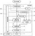
- FIG. 1 shows the configuration of a display device 1 according to Embodiment 1 of the present invention.
- the display device 1 includes a memory 11 and a schematic diagram selection section 12 , and a display layout setting section 13 is connected to the memory 11 and the schematic diagram selection section 12 .
- the display device 1 also includes an external communication circuit 10 connected to an external device (not shown), and the external communication circuit 10 is connected to a shooting position reading unit 14 .
- An image arrangement section 15 is connected to the display layout setting section 13 and the photographing position reading section 14 .
- a display control unit 16 and a monitor 17 are connected in sequence to the image layout unit 15 .
- a device control section 18 is connected to the external communication circuit 10 , memory 11 , schematic diagram selection section 12 , display layout setting section 13 , shooting position reading section 14 , image layout section 15 and display control section 16 .
- An input device 19 is connected to the device control section 18 .
- a processor 20 for the display device 1 is configured by the schematic diagram selection unit 12, the display layout setting unit 13, the shooting position reading unit 14, the image placement unit 15, the display control unit 16, and the device control unit 18.
- the display device 1 receives ultrasonic images from an external ultrasonic diagnostic device (not shown) or a server device (not shown) or the like, and is used for the user to interpret the received ultrasonic images.
- the memory 11 stores a plurality of display layouts each having a plurality of display areas for displaying a plurality of ultrasound images on one screen of the monitor 17 .
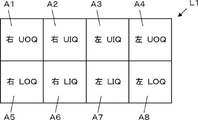
- the display layout L1 has eight display areas A1 to A8 for displaying ultrasound images.
- the four display areas A1, A2, A5, and A6 located on the left side of the eight display areas A1 to A8 correspond to areas obtained by dividing the right breast of the subject when viewed from the front into four areas centering on the nipple. do.
- the display area A1 corresponds to a so-called UOQ (Upper Outer Quadrant), which corresponds to an upper and outer area centered on the nipple, and the display area A2 corresponds to a so-called UIQ (Upper Inner Quadrant).
- the display area A5 corresponds to the lower and outer area around the nipple, which is called LOQ (Lower Outer Quadrant), and the display area A6 corresponds to the so-called LIQ (Lower Outer Quadrant).
- Inner Quadrant which corresponds to the lower and inner region centering on the nipple.
- the four display areas A3, A4, A7 and A8 located on the right side of the eight display areas A1 to A8 correspond to areas obtained by dividing the left breast of the subject when viewed from the front into four areas centering on the nipple. do. More specifically, the display area A3 corresponds to UIQ, the display area A4 corresponds to UOQ, the display area A7 corresponds to LIQ, and the display area A8 corresponds to LOQ.
- a plurality of schematic diagrams are known in which the breast of the subject is divided into a plurality of regions.
- a schematic diagram that divides the left and right breasts of the subject into four regions, UOQ, UIQ, LOQ, and LIQ, respectively, centering on the nipple, the left and right breasts of the subject, the central region where the nipple is located Schematic diagram of dividing the nipple into areas corresponding to the direction of 1 o'clock to 12 o'clock of the clock, and dividing the left and right breasts of the subject into concentric circles centered on the nipple when viewed from the front and side
- a schematic diagram or the like is known in which a plurality of contour lines are used to divide the nipple as the top when viewed from the top.
- the memory 11 stores a plurality of display layouts corresponding to a plurality of schematic diagrams of breasts, that is, a plurality of display layouts having a plurality of display areas corresponding to divided breast regions in a plurality of schematic diagrams of breasts.
- flash memory for example, flash memory, HDD (Hard Disc Drive), SSD (Solid State Drive), FD (Flexible Disc), MO disc (Magneto-Optical disc: magneto-optical disc), MT (Magnetic Tape), RAM (Random Access Memory), CD (Compact Disc), DVD (Digital Versatile Disc), SD card (Secure Digital A recording medium such as a secure digital card), a USB memory (Universal Serial Bus memory), or the like can be used.
- HDD Hard Disc Drive
- SSD Solid State Drive
- FD Fexible Disc
- MO disc Magnetic-Optical disc: magneto-optical disc
- MT Magnetic Tape
- RAM Random Access Memory
- CD Compact Disc
- DVD Digital Versatile Disc
- SD card Secure Digital
- USB memory Universal Serial Bus memory
- the schematic diagram selection unit 12 selects one of a plurality of types of schematic diagrams of the subject's breast based on the user's designation via the input device 19 . Information on the selected schematic diagram is sent to the display layout setting unit 13 .
- the display layout setting unit 13 sets a plurality of display areas of the display layout corresponding to the schematic diagram selected by the schematic diagram selection unit 12 from among the plurality of display layouts stored in the memory 11 to display the ultrasonic image on the monitor 17. Set as the display layout when displaying on one screen. Information on the plurality of display areas set by the display layout setting section 13 is sent to the image layout section 15 .
- the external communication circuit 10 communicates with an external device such as an external ultrasonic diagnostic device, a storage device, or a server device (not shown) to acquire an ultrasonic image from the external device.
- the external communication circuit 10 can perform so-called wired communication or wireless communication with an external device (not shown).
- the imaging position reading unit 14 reads the imaging position in the breast of the ultrasonic image acquired by the external communication circuit 10 from the ultrasonic image.
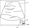
- the imaging position reading unit 14 acquires an ultrasonic image U as shown in FIG. 3, for example.
- a so-called schema image S is superimposed on the ultrasound image U to indicate the imaging position in the breast of the subject.
- a probe mark PM indicating is arranged.
- the schema image S in FIG. 3 represents the imaging position of the right breast of the subject because the projection P1 representing the side of the subject is arranged on the left side of the circular figure.
- the imaging position reading unit 14 performs image analysis on the schema image S on which the probe marks PM are arranged, and recognizes where the probe marks PM are arranged on the schema image S.
- the imaging position of the ultrasonic image U can be read.
- the imaging position reading unit 14 can also read the information stored in the DICOM tag to determine the imaging position of the ultrasonic image U. can be read.
- the image arrangement unit 15 automatically arranges the ultrasound images in the plurality of display areas set by the display layout setting unit 13 based on the imaging positions read by the imaging position reading unit 14, and arranges the ultrasonic images in the plurality of display areas.
- the arranged ultrasonic images are displayed on the monitor 17 .
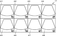
- the display layout setting unit 13 sets the eight display areas A1 to A8 of the display layout L1 shown in FIG. are arranged as shown in FIG. That is, an ultrasound image of the right breast captured at the UOQ imaging position is arranged in the display area A1, and an ultrasound image captured at the right breast UIQ imaging position is arranged in the display area A2, An ultrasound image of the right breast taken at the LOQ imaging position is arranged in the display area A5, and an ultrasound image of the right breast taken at the LIQ imaging position is arranged in the display area A6.
- an ultrasound image of the left breast captured at the UIQ imaging position is arranged in the display area A3, and an ultrasound image captured at the left breast UOQ imaging position is arranged in the display area A4,
- An ultrasound image of the left breast taken at the LIQ imaging position is arranged in the display area A7, and an ultrasound image of the left breast taken at the LOQ imaging position is arranged in the display area A8.
- the device control section 18 controls each section of the display device 1 according to a prerecorded program or the like. Under the control of the device control unit 18 , the display control unit 16 performs predetermined processing on the ultrasound image or the like and displays it on the monitor 17 .
- the monitor 17 performs various displays under the control of the display control unit 16.
- the monitor 17 includes, for example, a display device such as an LCD (Liquid Crystal Display) or an organic EL display (Organic Electroluminescence Display).
- the input device 19 is for the user to perform an input operation.
- the input device 19 is configured by, for example, a device such as a keyboard, mouse, trackball, touch pad, touch panel, or the like for a user to perform an input operation.
- the processor 20 having the schematic drawing selection unit 12, the display layout setting unit 13, the shooting position reading unit 14, the image placement unit 15, the display control unit 16 and the device control unit 18 is a CPU (Central Processing Unit). , and consists of a control program for causing the CPU to perform various processes, including FPGA (Field Programmable Gate Array), DSP (Digital Signal Processor), ASIC (Application Specific Integrated Circuit: application-specific integrated circuit), GPU (Graphics Processing Unit), other IC (Integrated Circuit), or may be configured by combining them .
- FPGA Field Programmable Gate Array
- DSP Digital Signal Processor
- ASIC Application Specific Integrated Circuit: application-specific integrated circuit
- GPU Graphics Processing Unit
- other IC Integrated Circuit
- the schematic diagram selection unit 12, the display layout setting unit 13, the photographing position reading unit 14, the image arrangement unit 15, the display control unit 16, and the device control unit 18 of the processor 20 are partially or wholly integrated into one CPU or the like. It can also be configured by integrating with.
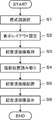
- step S1 when the user designates one of a plurality of types of schematic diagrams representing the breast of the subject via the input device 19, the schematic diagram selection unit 12 selects the schematic diagram designated by the user. do. For example, although not shown, a list of types of schematic diagrams is displayed on the monitor 17 , and the user can specify one of the types of schematic diagrams in the list via the input device 19 . Information on the schematic diagram selected in this manner is sent to the display layout setting unit 13 .
- step S2 the display layout setting unit 13 selects a plurality of display areas of the display layout corresponding to the type of schematic diagram selected in step S1 from among the plurality of display layouts stored in the memory 11, on the monitor 17. 1 screen above.
- the display layout setting unit 13 sets the display layout L1 shown in FIG. Two display areas A 1 to A 8 can be set on one screen of the monitor 17 .
- the display layout L1 includes four display areas A1, A2, A5 and A6 corresponding to four imaging positions of UOQ, UIQ, LOQ and LIQ of the right breast of the subject and UOQ and UIQ of the left breast of the subject. , LOQ and LIQ corresponding to the four imaging positions A3, A4, A7 and A8.
- the display layout setting unit 13 sets a plurality of display areas of the display layout corresponding to the schematic diagram of the breast on one screen of the monitor 17, the ultrasound images are displayed in the set display areas.
- the user can intuitively and easily grasp which ultrasound image corresponds to the imaging position.
- step S3 the imaging position reading unit 14 acquires an ultrasonic image U as shown in FIG.
- the imaging position reading unit 14 reads the imaging position of the ultrasonic image U from the ultrasonic image U obtained in step S3.
- the imaging position reading unit 14 performs image analysis on the schema image S on which the probe marks PM are arranged, and recognizes where the probe marks PM are arranged on the schema image S.
- the imaging position of the ultrasonic image U can be read.
- the imaging position reading unit 14 can also read the information stored in the DICOM tag to determine the imaging position of the ultrasonic image U. can be read.
- step S5 based on the display layout set in step S2 and the imaging position of the ultrasonic image read in step S4, the image layout unit 15 displays a display corresponding to the imaging position, as shown in FIG. Place the ultrasound image on the area.
- ultrasound images captured at corresponding imaging positions are arranged in eight display areas A1 to A8 of the display layout L1 shown in FIG.
- the user can save the trouble of arranging the ultrasonic images.
- the user can efficiently interpret ultrasound images.
- step S6 the image layout unit 15 causes the monitor 17 to display the ultrasound images laid out in the eight display areas A1 to A8 of the display layout L1 in step S5.
- the operation of the display device 1 according to the flowchart of FIG. 5 is completed.
- the display layout corresponding to the schematic diagram of the breast specified by the user is automatically set, the imaging position is read from the ultrasonic image, Since the ultrasonic images are automatically arranged in the display layout based on the imaging positions and displayed on the monitor 17, the user can intuitively grasp where the ultrasonic images corresponding to which imaging positions are arranged. It is possible to improve the efficiency of interpretation of ultrasound images. In addition, since the ultrasonic images at the imaging positions corresponding to the plurality of display areas of the display layout are automatically arranged, the user can save the trouble of arranging the ultrasonic images according to the display layout. can improve efficiency.
- the display layout L1 as shown in FIG. 2 has been described, as an example of the display layout stored in the memory 11, the left and right breasts of the subject are divided into a center area where the nipple is located and a center area around the nipple.
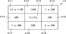
- the display layout L2 has nine display areas A11 to A19.
- the display area A11 corresponds to 10:00 or 11:00
- the display area A12 corresponds to 12:00
- the display area A13 corresponds to 1:00 or 2:00
- the display area A14 corresponds to 9:00.
- the display area A15 is the center area where the nipple is located, the display area A16 is the area corresponding to 3 o'clock on the clock, the display area A17 is the area corresponding to 7 o'clock or 8 o'clock on the clock, and the display area A18 is the area on the 6 o'clock clock.
- the corresponding area, display area A19, corresponds to 4 o'clock or 5 o'clock on the clock.
- the memory 11 stores the left and right breasts of the subject, when viewed from the front, are concentrically divided around the nipple, and when viewed from the side, a plurality of nipples are stored with the nipple as the top.
- a plurality of display layouts corresponding to schematic diagrams divided by contour lines are stored. Therefore, a display layout can be set according to the user's purpose or preference.
- the display layout setting unit 13 can change a plurality of consular areas already set on one screen of the monitor 17 based on the user's input operation via the input device 19 .
- the display layout setting unit 13 for example, based on the designation from the user, the number of display areas included in the display layout, the arrangement position of the display area corresponding to each shooting position, and the number of display areas arranged in the display area. You can set the magnification of the ultrasound image, etc.
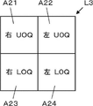
- the display layout setting unit 13 can set a display layout L3 having four display areas A21 to A24, as shown in FIG.
- the display area A21 of the display layout L3 corresponds to the right breast UOQ imaging position
- the display area A22 corresponds to the left breast UOQ imaging position
- the display area A23 corresponds to the right breast LOQ imaging position
- the display area A24 corresponds to the LOQ imaging position of the left breast.
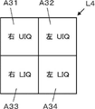
- the display layout setting unit 13 can also set four display areas A31 to A34 of the display layout L4 shown in FIG. 8 on one screen of the monitor 17, for example.
- the display area A31 corresponds to the UIQ imaging position for the right breast
- the display area A32 corresponds to the UIQ imaging position for the left breast
- the display area A33 corresponds to the LIQ imaging position for the right breast
- A34 corresponds to the LIQ imaging position of the left breast.
- the display layout setting unit 13 can also set the display areas A21 to A24 of the display layout L3 and the display areas A31 to A34 of the display layout L4 on one screen of the monitor 17, for example.
- the display areas A31 to A31 to A31 of the display layout L4 are displayed according to the user's instruction via the input device 19.
- An ultrasound image located at A 34 can be displayed on the monitor 17 .
- the user sequentially interprets the ultrasound images arranged in the display areas A21 to A24 of the display layout L3 and the ultrasound images displayed in the display areas A31 to A34 of the display layout L4, and reads the subject. diagnosis can be made.
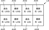
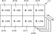
- the display layout setting unit 13 displays, for example, as shown in FIG. 9, an ultrasonic image captured in the latest examination of the subject and an ultrasonic image captured in the same subject in the past examination. It is also possible to set eight display areas A41 to A48 of the display layout L5 for displaying on one screen of the monitor 17. FIG. 9
- the display area A41 corresponds to the imaging position of the right breast UOQ imaged in the past examination
- the display area A42 corresponds to the imaging position of the right breast UOQ imaged in the latest examination
- the display area A43 corresponds to the UIQ imaging position of the right breast imaged in the past examination
- the display area A44 corresponds to the UIQ imaging position of the right breast imaged in the latest examination
- the display area A45 corresponds to the imaging position of the UIQ in the past examination.
- the display area A46 corresponds to the LOQ imaging position of the right breast imaged in the latest examination
- the display area A47 corresponds to the LOQ imaging position of the right breast imaged in the previous examination.
- the display area A48 corresponds to the LIQ imaging position of the right breast imaged in the latest examination.
- the display layout setting unit 13 sets the date and time of the past examination when the ultrasonic image was captured, which is arranged in the display layout L5, and the display area A41 to A41 of the display layout L5.
- the imaging position and the like of the ultrasonic image displayed in A49 can be set.
- a plurality of display areas are set on one screen of the monitor 17 for displaying the ultrasonic image captured in the latest examination of the same subject and the ultrasonic image captured in the past examination.
- the user can easily compare the latest test result of the subject with the past test result, and can improve the efficiency of interpreting the ultrasonic image.
- the display layout setting unit 13 displays, for example, an ultrasonic image taken by an ultrasonic examination and an examination image taken by an examination other than the ultrasonic examination on one screen of the monitor 17, as shown in FIG.
- Six display areas A51 to A56 of the display layout L6 for displaying can be set on one screen of the monitor 17.
- FIG. Display areas A51 to A56 in FIG. 10 are for displaying a so-called mammography image and an ultrasound image side by side on one screen.
- a display area A51 corresponds to a so-called MLO (Medio-lateral-Oblique) mammography image of the right breast
- a display area A52 corresponds to a so-called CC (Cranio-Caudal) mammography image of the right breast
- the display area A53 corresponds to the ultrasound image at the UOQ imaging position of the right breast
- the display area A54 corresponds to the ultrasound image at the UIQ imaging position of the right breast
- the area A55 corresponds to the ultrasound image of the right breast at the LOQ imaging position
- the display area A56 corresponds to the ultrasound image of the right breast at the LIQ imaging position.
- the display layout setting unit 13 can set a display layout for displaying so-called MRI (Magnetic Resonance Imaging) images or so-called CT (Computed Tomography) images instead of mammography images. .
- the display layout setting unit 13 sets a plurality of display areas for displaying a plurality of types of examination images taken in a plurality of types of examinations other than the ultrasonic examination together with the ultrasonic image. You can also set it on the screen.
- a plurality of display areas for displaying an ultrasonic image of the same subject taken in an ultrasonic examination and an examination image taken in an examination other than the ultrasonic examination are displayed on one screen of the monitor 17.
- the user can easily compare the ultrasonic image and the inspection image, and can improve the efficiency of interpretation of the ultrasonic image.
- the display layout setting unit 13 selects a plurality of display regions corresponding to one breast from among a plurality of display regions corresponding to both the left and right breasts of the subject.
- a plurality of display areas corresponding to the other breast are set by setting based on the imaging position read by 14 or an instruction from the user, and by horizontally reversing the arrangement of the imaging positions corresponding to the set plurality of display areas. can.
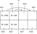
- corresponding shooting positions are set in the four display areas A61, A62, A65 and A66 located on the left side of the eight display areas A61 to A68.
- a display area A61 corresponds to the right breast UOQ imaging position
- a display area A62 corresponds to the right breast UIQ imaging position
- a display area A65 corresponds to the right breast LOQ imaging position.
- A66 corresponds to the LIQ imaging position of the right breast.
- the display layout setting unit 13 sets, for example, the imaging position of the UOQ of the left breast in the display area A64 arranged at a position symmetrical to the display area A61 with respect to the center line C, and The imaging position of the UIQ of the left breast is set in the display area A63 arranged in a position symmetrical to the display area A62 with respect to C, and arranged in a position symmetrical to the display area A65 with respect to the center line C.
- the left breast LOQ imaging position is set in the display area A68, and the left breast LIQ imaging position is set in the display area A67 arranged at a position symmetrical to the display area A66 with respect to the center line C. set.
- the display layout setting unit 13 can set the eight display areas A1 to A8 of the display layout L1 shown in FIG.
- the user's input operation can be simplified, and the efficiency can be improved.
- the user can actually interpret radiograms.
- the display layout setting section 13 can set, for example, a plurality of display areas for displaying a B-mode image and a color image on one screen of the monitor 17 .
- the user can easily compare a B-mode image and a color image captured at the same imaging position, thereby improving the efficiency of interpreting ultrasound images.
- the eight display areas A1 to A8 of the display layout L1 shown in FIG. 2 there may be cases where ultrasound images corresponding to some display areas are not captured.
- a display area in which the ultrasonic image is not arranged by the image arrangement unit 15 such a display area may be displayed as a blank when the ultrasonic image is displayed on the monitor 17, for example.
- the user can intuitively grasp the imaging positions of the ultrasonic images displayed in the eight display areas A1 to A8 of the display layout L1, thereby improving the interpretation efficiency.
- the user can intuitively grasp which positions of the subject's breast are being imaged and which positions are not being imaged.
- the display device 1 may have a plurality of monitors arranged adjacent to each other instead of having one monitor 17 .
- one screen is formed by a plurality of monitors adjacent to each other, and the display layout setting unit 13 arranges a plurality of display areas of the display layout corresponding to the schematic diagram selected by the schematic diagram selection unit 12 so that they are adjacent to each other.
- the display layout setting unit 13 arranges a plurality of display areas of the display layout corresponding to the schematic diagram selected by the schematic diagram selection unit 12 so that they are adjacent to each other.
- the schematic diagram selection unit 12 selects the schematic diagram designated by the user in step S1, but the schematic diagram is newly selected by the user. Alternatively, it is also possible to continue to select schematic views selected in past inspections. This saves the user the trouble of designating a schematic diagram.
- Embodiment 2 In Embodiment 1, a plurality of display areas with display layouts corresponding to the types of breast schematic diagrams specified by the user are set. A region can also be set.
- the term "finding" as used herein refers to a site suspected of having an abnormality such as a tumor in the breast of the subject.
- FIG. 12 shows the configuration of a display device 1A according to the second embodiment.
- a display device 1A according to the second embodiment is the same as the display device 1 according to the first embodiment shown in FIG.
- a processor 20A including a finding determination unit 21 is provided instead of the .
- the finding determination section 21 is connected to the display layout setting section 13 and the device control section 18A.
- the finding determination unit 21 acquires an ultrasonic image from an external ultrasonic diagnostic device (not shown) or an external server device (not shown) or the like via the external communication circuit 10, and determines whether or not there is a finding in the acquired ultrasonic image. It is.
- the finding determination unit 21 can determine the presence or absence of findings by performing image analysis on the ultrasound image and performing processing for recognizing findings included in the ultrasound image.
- the finding determination unit 21 can determine that there is a finding when a finding is recognized in the ultrasonic image, and can determine that there is no finding when the finding is not recognized in the ultrasonic image.
- the finding determination unit 21 can automatically recognize findings in ultrasonic images using, for example, a so-called CAD (Computer-Aided Diagnosis) system. Further, the finding determination unit 21 can automatically recognize findings in an ultrasonic image using a method such as so-called machine learning.
- CAD Computer-Aided Diagnosis
- the finding determination unit 21 determines whether the annotation and the measurement line Findings can also be recognized by extracting
- the finding determination unit 21 determines that there is a finding when a plurality of ultrasonic images captured at one imaging position are input from an external ultrasonic diagnostic apparatus (not shown) or an external server device (not shown). It can also be determined that there is no finding when at most one ultrasound image is input at one imaging position.
- a combination of a plurality of ultrasound images captured at one imaging position includes, for example, a B-mode image and an ultrasound image of a type other than the B-mode image, such as a so-called Doppler image and a so-called elasticity image.
- a plurality of ultrasonic images captured at one imaging position also includes a plurality of ultrasonic images obtained by imaging the same part of the subject with slightly shifted imaging positions.
- the finding determination unit 21 determines that there is a finding when an inspection image other than an ultrasonic image is input from an external inspection device (not shown) or an external server device (not shown) or the like. In some cases, it can be determined that there are no findings.
- the display layout setting unit 13 selects a plurality of display layouts corresponding to the schematic diagram of the breast selected by the schematic diagram selecting unit 12, as in the first embodiment. is set on one screen of the monitor 17 .
- the display layout setting unit 13 sets a plurality of display areas on one screen of the monitor 17 with display layouts different from those in the case where the findings determination unit 21 determines that there are findings, and that there are no findings. do.
- the display areas A71 to A78 can be set so as to switch between and display a plurality of ultrasonic images captured at this imaging position and inspection images other than the ultrasonic images according to the user's input operation.
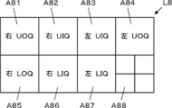
- the display layout setting unit 13 for example, as shown in FIG. 14, among the eight display areas A81 to A88 of the display layout L8, in the display area A88 corresponding to the imaging position where the finding is recognized,
- the display areas A81 to A88 can be set so that a plurality of captured ultrasonic images and inspection images other than the ultrasonic images are displayed side by side.
- the display layout setting unit 13 sets, for example, to arrange one representative ultrasound image in a display area corresponding to an imaging position where a finding is found.
- a plurality of display areas of the same first display layout are set on one screen of the monitor 17, and further, other ultrasonic images captured at the imaging position where the findings are recognized and inspection images other than the ultrasonic images
- the finding determination unit 21 determines the presence or absence of findings in the ultrasound image
- the display layout setting unit 13 performs different display depending on the presence or absence of findings. Since a plurality of layout display areas are set on one screen, the user can not only intuitively grasp which imaging position the ultrasonic images displayed on the monitor 17 are ultrasonic images, but also can identify findings. Since the ultrasonic image or inspection image included in the image can also be easily confirmed, the efficiency of radiogram interpretation can be further improved.
Landscapes
- Health & Medical Sciences (AREA)
- Life Sciences & Earth Sciences (AREA)
- Engineering & Computer Science (AREA)
- Physics & Mathematics (AREA)
- Medical Informatics (AREA)
- Animal Behavior & Ethology (AREA)
- Radiology & Medical Imaging (AREA)
- Nuclear Medicine, Radiotherapy & Molecular Imaging (AREA)
- Biomedical Technology (AREA)
- Heart & Thoracic Surgery (AREA)
- Biophysics (AREA)
- Molecular Biology (AREA)
- Surgery (AREA)
- Pathology (AREA)
- General Health & Medical Sciences (AREA)
- Public Health (AREA)
- Veterinary Medicine (AREA)
- Theoretical Computer Science (AREA)
- Multimedia (AREA)
- Human Computer Interaction (AREA)
- General Engineering & Computer Science (AREA)
- General Physics & Mathematics (AREA)
- Ultra Sonic Daignosis Equipment (AREA)
Abstract
Description
また、表示レイアウト設定部は、ユーザの指示に基づいて、既に1画面上に設定された複数の表示領域を変更することができる。
また、表示レイアウト設定部は、ユーザの指示に基づいて、同一の被検体に対して行われた検査において撮影された超音波画像と、超音波検査以外の検査により取得された検査画像とを並べて表示するための複数の表示領域を1画面上に設定することもできる。
また、表示レイアウト設定部は、ユーザの指示に基づいて、同一の被検体に対して行われた超音波検査において撮影されたBモード画像とカラー画像とを並べて表示するための複数の表示領域を1画面上に設定することができる。
撮影位置読み取り部は、超音波画像に付随するタグに書き込まれている超音波プローブの位置に基づいて超音波画像の撮影位置を読み取ることもできる。
また、表示装置の制御方法において、ユーザの指示に基づいて、既に1画面上に設定された複数の表示領域を変更することができる。
また、表示装置の制御方法において、ユーザの指示に基づいて、同一の被検体に対して行われた検査において撮影された超音波画像と、超音波検査以外の検査により取得された検査画像とを並べて表示するための複数の表示領域を1画面上に設定することもできる。
また、表示装置の制御方法において、ユーザの指示に基づいて、同一の被検体に対して行われた超音波検査において撮影されたBモード画像とカラー画像とを並べて表示するための複数の表示領域を1画面上に設定することができる。
また、表示装置の制御方法において、超音波画像に付随するタグに書き込まれている超音波プローブの位置に基づいて超音波画像の撮影位置を読み取ることもできる。
以下に記載する構成要件の説明は、本発明の代表的な実施態様に基づいてなされるが、本発明はそのような実施態様に限定されるものではない。
なお、本明細書において、「~」を用いて表される数値範囲は、「~」の前後に記載される数値を下限値および上限値として含む範囲を意味する。
本明細書において、「同一」、「同じ」は、技術分野で一般的に許容される誤差範囲を含むものとする。
図1に、本発明の実施の形態1に係る表示装置1の構成を示す。表示装置1は、メモリ11と模式図選択部12を備え、メモリ11および模式図選択部12に、表示レイアウト設定部13が接続されている。また、表示装置1は、図示しない外部の機器に接続される外部通信回路10を備えており、外部通信回路10に撮影位置読み取り部14が接続されている。また、表示レイアウト設定部13と撮影位置読み取り部14に、画像配置部15が接続されている。また、画像配置部15に、表示制御部16およびモニタ17が順次接続されている。
また、外部通信回路10、メモリ11、模式図選択部12、表示レイアウト設定部13、撮影位置読み取り部14、画像配置部15および表示制御部16に、装置制御部18が接続されている。また、装置制御部18に入力装置19が接続されている。
例えば図2に示すように、表示レイアウトL1は、超音波画像を表示するための8つの表示領域A1~A8を有している。8つの表示領域A1~A8のうち左側に位置する4つの表示領域A1、A2、A5およびA6は、正面から見た場合の被検体の右の乳房を、ニップルを中心として4分割した領域に相当する。より具体的には、表示領域A1は、いわゆるUOQ(Upper Outer Quadrant)と呼ばれる、ニップルを中心として上側且つ外側の領域に相当し、表示領域A2は、いわゆるUIQ(Upper Inner Quadrant)と呼ばれる、ニップルを中心として上側且つ内側の領域に相当し、表示領域A5は、いわゆるLOQ(Lower Outer Quadrant)と呼ばれる、ニップルを中心として下側且つ外側の領域に相当し、表示領域A6は、いわゆるLIQ(Lower Inner Quadrant)と呼ばれる、ニップルを中心として下側且つ内側の領域に相当する。
また、超音波画像UのDICOMタグに撮影位置に関する情報が格納されている場合には、撮影位置読み取り部14は、DICOMタグに格納された情報を読み取ることによっても、超音波画像Uの撮影位置を読み取ることができる。
表示制御部16は、装置制御部18の制御の下で、超音波画像等に所定の処理を施して、モニタ17に表示する。
これにより、図5のフローチャートに従う表示装置1の動作が終了する。
また、表示レイアウトの複数の表示領域に対応する撮影位置の超音波画像が自動的に配置されるため、ユーザは、超音波画像を表示レイアウトに従って配置する手間を省くことができ、これによっても読影効率を向上できる。
実施の形態1では、ユーザに指定された乳房の模式図の種類に対応する表示レイアウトの複数の表示領域が設定されているが、被検体の検査箇所における所見の有無を加味して複数の表示領域を設定することもできる。ここで、所見とは、被検体の乳房に腫瘤等の異常が発生している疑いのある箇所のことをいう。
実施の形態2に係る表示装置1Aは、図1に示す実施の形態1の表示装置1において、所見判定部21が追加され、装置制御部18の代わりに装置制御部18Aが備えられ、プロセッサ20の代わりに所見判定部21を含むプロセッサ20Aを備えたものである。所見判定部21は、表示レイアウト設定部13および装置制御部18Aに接続されている。
また、1つの撮影位置において撮影された複数の超音波画像には、撮影位置をわずかにずらして被検体の同一の部位を撮影した複数の超音波画像も含まれる。
表示レイアウト設定部13は、所見判定部21により所見なしの判定がなされた場合に、実施の形態1と同様に、模式図選択部12により選択された乳房の模式図に対応する表示レイアウトの複数の表示領域をモニタ17の1画面上に設定する。
Claims (20)
- 1画面を形成する1つまたは互いに隣接する複数のモニタと、
複数の超音波画像を前記1画面上に表示するための複数の表示領域を有する複数の表示レイアウトを記憶するメモリと、
被検体の乳房を複数の領域に区分けした複数の模式図のうち1つをユーザの指定に基づいて選択する模式図選択部と、
前記模式図選択部により選択された模式図に対応する表示レイアウトの複数の表示領域を前記1画面上に設定する表示レイアウト設定部と、
超音波画像から前記超音波画像の撮影位置を読み取る撮影位置読み取り部と、
前記撮影位置読み取り部により読み取られた撮影位置に基づいて、前記表示レイアウト設定部により設定された表示領域に前記超音波画像を配置する画像配置部とを備える
表示装置。 - 前記表示レイアウト設定部は、前記模式図選択部により選択された前記模式図における複数の領域に対応する位置に配置された複数の表示領域を前記1画面上に設定する請求項1に記載の表示装置。
- 前記表示レイアウト設定部は、ユーザの指示に基づいて、既に前記1画面上に設定された前記複数の表示領域を変更する請求項1または2に記載の表示装置。
- 超音波画像における所見の有無を判定する所見判定部を備え、
前記表示レイアウト設定部は、前記所見判定部により所見ありと判定された場合と、所見なしと判定された場合とにおいて、互いに異なる表示レイアウトの複数の表示領域を前記1画面上に設定する請求項1~3のいずれか一項に記載の表示装置。 - 前記表示レイアウト設定部は、ユーザの指示に基づいて、同一の被検体に対して行われた最新の検査において撮影された超音波画像と、過去の検査において撮影された超音波画像とを並べて表示するための複数の表示領域を前記1画面上に設定する請求項1~4のいずれか一項に記載の表示装置。
- 前記表示レイアウト設定部は、ユーザの指示に基づいて、同一の被検体に対して行われた検査において撮影された超音波画像と、超音波検査以外の検査により取得された検査画像とを並べて表示するための複数の表示領域を前記1画面上に設定する請求項1~4のいずれか一項に記載の表示装置。
- 前記表示レイアウト設定部は、被検体の左右両方の乳房に対応する複数の表示領域のうち、一方の乳房に対応する複数の表示領域を前記撮影位置読み取り部により読み取られた撮影位置またはユーザの指示に基づいて設定し、設定された複数の表示領域に対応する撮影位置の配置を左右反転させることにより、他方の乳房に対応する複数の表示領域を設定する請求項1~6のいずれか一項に記載の表示装置。
- 前記表示レイアウト設定部は、ユーザの指示に基づいて、同一の被検体に対して行われた超音波検査において撮影されたBモード画像とカラー画像とを並べて表示するための複数の表示領域を前記1画面上に設定する請求項1~7のいずれか一項に記載の表示装置。
- 前記撮影位置読み取り部は、前記超音波画像に重畳表示され且つ乳房に対する撮影時の超音波プローブの位置を示すシェーマ画像を解析することにより前記超音波画像の撮影位置を読み取る請求項1~8のいずれか一項に記載の表示装置。
- 前記撮影位置読み取り部は、前記超音波画像に付随するタグに書き込まれている超音波プローブの位置に基づいて前記超音波画像の撮影位置を読み取る請求項1~8のいずれか一項に記載の表示装置。
- 複数の超音波画像を1つまたは互いに隣接する複数のモニタにより形成される1画面上に表示するための複数の表示領域を有する複数の表示レイアウトがメモリに記憶され、
被検体の乳房を複数の領域に区分けした複数の模式図のうち1つをユーザの指示に基づいて選択し、
選択された模式図に対応する表示レイアウトの複数の表示領域を前記1画面上に設定し、
超音波画像から前記超音波画像の撮影位置を読み取り、
読み取られた撮影位置に基づいて、設定された表示領域に前記超音波画像を配置する
表示装置の制御方法。 - ユーザの指示に基づいて選択された前記模式図における複数の領域に対応する位置に配置された複数の表示領域を前記1画面上に設定する請求項11に記載の表示装置の制御方法。
- ユーザの指示に基づいて、既に前記1画面上に設定された前記複数の表示領域を変更する請求項11または12に記載の表示装置の制御方法。
- 超音波画像における所見の有無を判定し、
所見ありと判定された場合と、所見なしと判定された場合とにおいて、互いに異なる表示レイアウトの複数の表示領域を前記1画面上に設定する請求項11~13のいずれか一項に記載の表示装置の制御方法。 - ユーザの指示に基づいて、同一の被検体に対して行われた最新の検査において撮影された超音波画像と、過去の検査において撮影された超音波画像とを並べて表示するための複数の表示領域を前記1画面上に設定する請求項11~14のいずれか一項に記載の表示装置の制御方法。
- ユーザの指示に基づいて、同一の被検体に対して行われた検査において撮影された超音波画像と、超音波検査以外の検査により取得された検査画像とを並べて表示するための複数の表示領域を前記1画面上に設定する請求項11~14のいずれか一項に記載の表示装置の制御方法。
- 被検体の左右両方の乳房に対応する複数の表示領域のうち、一方の乳房に対応する複数の表示領域を、読み取られた撮影位置またはユーザの指示に基づいて設定し、設定された複数の表示領域に対応する撮影位置の配置を左右反転させることにより、他方の乳房に対応する複数の表示領域を設定する請求項11~16のいずれか一項に記載の表示装置の制御方法。
- ユーザの指示に基づいて、同一の被検体に対して行われた超音波検査において撮影されたBモード画像とカラー画像とを並べて表示する表示するための複数の表示領域を前記1画面上に設定する請求項11~17のいずれか一項に記載の表示装置の制御方法。
- 前記超音波画像に重畳表示され且つ乳房に対する撮影時の超音波プローブの位置を示すシェーマ画像を解析することにより前記超音波画像の撮影位置を読み取る請求項11~18のいずれか一項に記載の表示装置の制御方法。
- 前記超音波画像に付随するタグに書き込まれている超音波プローブの位置に基づいて前記超音波画像の撮影位置を読み取る請求項11~18のいずれか一項に記載の表示装置の制御方法。
Priority Applications (3)
| Application Number | Priority Date | Filing Date | Title |
|---|---|---|---|
| EP22766787.0A EP4306060A4 (en) | 2021-03-08 | 2022-02-18 | DISPLAY DEVICE AND DISPLAY DEVICE CONTROL METHOD |
| JP2023505259A JPWO2022190824A1 (ja) | 2021-03-08 | 2022-02-18 | |
| US18/461,294 US12336859B2 (en) | 2021-03-08 | 2023-09-05 | Display device and control method of display device |
Applications Claiming Priority (2)
| Application Number | Priority Date | Filing Date | Title |
|---|---|---|---|
| JP2021-036485 | 2021-03-08 | ||
| JP2021036485 | 2021-03-08 |
Related Child Applications (1)
| Application Number | Title | Priority Date | Filing Date |
|---|---|---|---|
| US18/461,294 Continuation US12336859B2 (en) | 2021-03-08 | 2023-09-05 | Display device and control method of display device |
Publications (1)
| Publication Number | Publication Date |
|---|---|
| WO2022190824A1 true WO2022190824A1 (ja) | 2022-09-15 |
Family
ID=83227696
Family Applications (1)
| Application Number | Title | Priority Date | Filing Date |
|---|---|---|---|
| PCT/JP2022/006742 Ceased WO2022190824A1 (ja) | 2021-03-08 | 2022-02-18 | 表示装置および表示装置の制御方法 |
Country Status (4)
| Country | Link |
|---|---|
| US (1) | US12336859B2 (ja) |
| EP (1) | EP4306060A4 (ja) |
| JP (1) | JPWO2022190824A1 (ja) |
| WO (1) | WO2022190824A1 (ja) |
Cited By (1)
| Publication number | Priority date | Publication date | Assignee | Title |
|---|---|---|---|---|
| WO2024181188A1 (ja) * | 2023-03-02 | 2024-09-06 | 富士フイルム株式会社 | 超音波診断装置および超音波診断装置の制御方法 |
Families Citing this family (1)
| Publication number | Priority date | Publication date | Assignee | Title |
|---|---|---|---|---|
| US12452356B2 (en) * | 2020-05-11 | 2025-10-21 | Sony Group Corporation | Communication apparatus, method, and program having a signal strength compass |
Citations (5)
| Publication number | Priority date | Publication date | Assignee | Title |
|---|---|---|---|---|
| JP2007236823A (ja) * | 2006-03-10 | 2007-09-20 | Toshiba Corp | 超音波診断装置 |
| JP2014014489A (ja) * | 2012-07-09 | 2014-01-30 | Toshiba Corp | 画像表示装置 |
| JP2015100661A (ja) | 2013-11-28 | 2015-06-04 | コニカミノルタ株式会社 | 医用画像システム及びプログラム |
| JP2017070608A (ja) * | 2015-10-09 | 2017-04-13 | コニカミノルタ株式会社 | 超音波画像診断装置 |
| JP2018027298A (ja) * | 2016-08-10 | 2018-02-22 | キヤノンメディカルシステムズ株式会社 | 医用処理装置、超音波診断装置および医用処理プログラム |
Family Cites Families (10)
| Publication number | Priority date | Publication date | Assignee | Title |
|---|---|---|---|---|
| US7615008B2 (en) * | 2000-11-24 | 2009-11-10 | U-Systems, Inc. | Processing and displaying breast ultrasound information |
| US7945083B2 (en) * | 2006-05-25 | 2011-05-17 | Carestream Health, Inc. | Method for supporting diagnostic workflow from a medical imaging apparatus |
| JP2008073304A (ja) * | 2006-09-22 | 2008-04-03 | Gifu Univ | 超音波乳房診断システム |
| US10603007B2 (en) * | 2009-11-27 | 2020-03-31 | Qview Medical, Inc. | Automated breast ultrasound equipment and methods using enhanced navigator aids |
| US20120014578A1 (en) * | 2010-07-19 | 2012-01-19 | Qview Medical, Inc. | Computer Aided Detection Of Abnormalities In Volumetric Breast Ultrasound Scans And User Interface |
| US11298104B2 (en) | 2016-08-10 | 2022-04-12 | Canon Medical Systems Corporation | Medical processing apparatus, ultrasound diagnostic apparatus, and medical processing method |
| JP6812193B2 (ja) * | 2016-10-07 | 2021-01-13 | キヤノン株式会社 | 画像表示システム、画像表示方法、及びプログラム |
| JP7066358B2 (ja) * | 2016-11-10 | 2022-05-13 | キヤノンメディカルシステムズ株式会社 | 超音波診断装置、医用画像処理装置、及び医用画像処理プログラム |
| JP6845071B2 (ja) * | 2017-04-12 | 2021-03-17 | 富士フイルム株式会社 | 自動レイアウト装置および自動レイアウト方法並びに自動レイアウトプログラム |
| WO2019190798A1 (en) * | 2018-03-25 | 2019-10-03 | Wang Shih Ping | Breast ultrasound scanning |
-
2022
- 2022-02-18 EP EP22766787.0A patent/EP4306060A4/en active Pending
- 2022-02-18 WO PCT/JP2022/006742 patent/WO2022190824A1/ja not_active Ceased
- 2022-02-18 JP JP2023505259A patent/JPWO2022190824A1/ja active Pending
-
2023
- 2023-09-05 US US18/461,294 patent/US12336859B2/en active Active
Patent Citations (5)
| Publication number | Priority date | Publication date | Assignee | Title |
|---|---|---|---|---|
| JP2007236823A (ja) * | 2006-03-10 | 2007-09-20 | Toshiba Corp | 超音波診断装置 |
| JP2014014489A (ja) * | 2012-07-09 | 2014-01-30 | Toshiba Corp | 画像表示装置 |
| JP2015100661A (ja) | 2013-11-28 | 2015-06-04 | コニカミノルタ株式会社 | 医用画像システム及びプログラム |
| JP2017070608A (ja) * | 2015-10-09 | 2017-04-13 | コニカミノルタ株式会社 | 超音波画像診断装置 |
| JP2018027298A (ja) * | 2016-08-10 | 2018-02-22 | キヤノンメディカルシステムズ株式会社 | 医用処理装置、超音波診断装置および医用処理プログラム |
Non-Patent Citations (1)
| Title |
|---|
| See also references of EP4306060A4 |
Cited By (1)
| Publication number | Priority date | Publication date | Assignee | Title |
|---|---|---|---|---|
| WO2024181188A1 (ja) * | 2023-03-02 | 2024-09-06 | 富士フイルム株式会社 | 超音波診断装置および超音波診断装置の制御方法 |
Also Published As
| Publication number | Publication date |
|---|---|
| JPWO2022190824A1 (ja) | 2022-09-15 |
| EP4306060A1 (en) | 2024-01-17 |
| US12336859B2 (en) | 2025-06-24 |
| US20230404532A1 (en) | 2023-12-21 |
| EP4306060A4 (en) | 2024-08-28 |
Similar Documents
| Publication | Publication Date | Title |
|---|---|---|
| US8907952B2 (en) | Reparametrized bull's eye plots | |
| US10984530B1 (en) | Enhanced medical images processing method and computing device | |
| US9168007B2 (en) | Computer-aided diagnostic apparatus | |
| CN101299966B (zh) | 图像解析装置及方法 | |
| US9380991B2 (en) | Computerized tomography (CT) method and CT system | |
| JP6302934B2 (ja) | コンピュータ支援による関心組織の特定 | |
| US11222728B2 (en) | Medical image display apparatus, medical image display method, and medical image display program | |
| US20080118138A1 (en) | Facilitating comparison of medical images | |
| US12336859B2 (en) | Display device and control method of display device | |
| US20230223124A1 (en) | Information processing apparatus, information processing method, and information processing program | |
| US20150150531A1 (en) | Medical Imaging System And Program | |
| CN111276221B (zh) | 椎骨影像信息的处理方法、显示方法及存储介质 | |
| JP6430500B2 (ja) | 腫瘍の奏効測定を支援するための方法 | |
| US7548639B2 (en) | Diagnosis assisting system and storage medium having diagnosis assisting program stored therein | |
| CN101010696A (zh) | 利用多形式可视化监测疾病发展和对治疗反应的系统和方法 | |
| US20200082931A1 (en) | Diagnostic support apparatus | |
| JP2012143368A (ja) | 医用画像表示装置及びプログラム | |
| US20210272278A1 (en) | Medical information processing system and medical information processing method | |
| US11295442B2 (en) | Medical information display apparatus displaying cavity region in brain image, medical information display method, and medical information display program | |
| EP3967221A1 (en) | Quantitative imaging of the heart muscle | |
| JP2023032238A (ja) | 医用画像表示装置 | |
| JP5533198B2 (ja) | 医用画像表示装置及びプログラム | |
| JP7626626B2 (ja) | 読影支援装置及び読影支援装置の作動方法 | |
| US20230317249A1 (en) | Medical support device, and operation method and operation program of medical support device | |
| JP2008289901A (ja) | コンピュータ支援診断装置 |
Legal Events
| Date | Code | Title | Description |
|---|---|---|---|
| 121 | Ep: the epo has been informed by wipo that ep was designated in this application |
Ref document number: 22766787 Country of ref document: EP Kind code of ref document: A1 |
|
| WWE | Wipo information: entry into national phase |
Ref document number: 2023505259 Country of ref document: JP |
|
| WWE | Wipo information: entry into national phase |
Ref document number: 2022766787 Country of ref document: EP |
|
| NENP | Non-entry into the national phase |
Ref country code: DE |
|
| ENP | Entry into the national phase |
Ref document number: 2022766787 Country of ref document: EP Effective date: 20231009 |