WO2022190627A1 - 流体回路デバイス及び細胞培養用デバイス - Google Patents
流体回路デバイス及び細胞培養用デバイス Download PDFInfo
- Publication number
- WO2022190627A1 WO2022190627A1 PCT/JP2022/001245 JP2022001245W WO2022190627A1 WO 2022190627 A1 WO2022190627 A1 WO 2022190627A1 JP 2022001245 W JP2022001245 W JP 2022001245W WO 2022190627 A1 WO2022190627 A1 WO 2022190627A1
- Authority
- WO
- WIPO (PCT)
- Prior art keywords
- pump
- block
- connection
- tube
- tank
- Prior art date
- Legal status (The legal status is an assumption and is not a legal conclusion. Google has not performed a legal analysis and makes no representation as to the accuracy of the status listed.)
- Ceased
Links
Images





Classifications
-
- C—CHEMISTRY; METALLURGY
- C12—BIOCHEMISTRY; BEER; SPIRITS; WINE; VINEGAR; MICROBIOLOGY; ENZYMOLOGY; MUTATION OR GENETIC ENGINEERING
- C12M—APPARATUS FOR ENZYMOLOGY OR MICROBIOLOGY; APPARATUS FOR CULTURING MICROORGANISMS FOR PRODUCING BIOMASS, FOR GROWING CELLS OR FOR OBTAINING FERMENTATION OR METABOLIC PRODUCTS, i.e. BIOREACTORS OR FERMENTERS
- C12M29/00—Means for introduction, extraction or recirculation of materials, e.g. pumps
- C12M29/18—External loop; Means for reintroduction of fermented biomass or liquid percolate
-
- C—CHEMISTRY; METALLURGY
- C12—BIOCHEMISTRY; BEER; SPIRITS; WINE; VINEGAR; MICROBIOLOGY; ENZYMOLOGY; MUTATION OR GENETIC ENGINEERING
- C12M—APPARATUS FOR ENZYMOLOGY OR MICROBIOLOGY; APPARATUS FOR CULTURING MICROORGANISMS FOR PRODUCING BIOMASS, FOR GROWING CELLS OR FOR OBTAINING FERMENTATION OR METABOLIC PRODUCTS, i.e. BIOREACTORS OR FERMENTERS
- C12M23/00—Constructional details, e.g. recesses, hinges
- C12M23/40—Manifolds; Distribution pieces
-
- C—CHEMISTRY; METALLURGY
- C12—BIOCHEMISTRY; BEER; SPIRITS; WINE; VINEGAR; MICROBIOLOGY; ENZYMOLOGY; MUTATION OR GENETIC ENGINEERING
- C12M—APPARATUS FOR ENZYMOLOGY OR MICROBIOLOGY; APPARATUS FOR CULTURING MICROORGANISMS FOR PRODUCING BIOMASS, FOR GROWING CELLS OR FOR OBTAINING FERMENTATION OR METABOLIC PRODUCTS, i.e. BIOREACTORS OR FERMENTERS
- C12M23/00—Constructional details, e.g. recesses, hinges
- C12M23/02—Form or structure of the vessel
- C12M23/16—Microfluidic devices; Capillary tubes
-
- C—CHEMISTRY; METALLURGY
- C12—BIOCHEMISTRY; BEER; SPIRITS; WINE; VINEGAR; MICROBIOLOGY; ENZYMOLOGY; MUTATION OR GENETIC ENGINEERING
- C12M—APPARATUS FOR ENZYMOLOGY OR MICROBIOLOGY; APPARATUS FOR CULTURING MICROORGANISMS FOR PRODUCING BIOMASS, FOR GROWING CELLS OR FOR OBTAINING FERMENTATION OR METABOLIC PRODUCTS, i.e. BIOREACTORS OR FERMENTERS
- C12M23/00—Constructional details, e.g. recesses, hinges
- C12M23/20—Material Coatings
-
- C—CHEMISTRY; METALLURGY
- C12—BIOCHEMISTRY; BEER; SPIRITS; WINE; VINEGAR; MICROBIOLOGY; ENZYMOLOGY; MUTATION OR GENETIC ENGINEERING
- C12M—APPARATUS FOR ENZYMOLOGY OR MICROBIOLOGY; APPARATUS FOR CULTURING MICROORGANISMS FOR PRODUCING BIOMASS, FOR GROWING CELLS OR FOR OBTAINING FERMENTATION OR METABOLIC PRODUCTS, i.e. BIOREACTORS OR FERMENTERS
- C12M23/00—Constructional details, e.g. recesses, hinges
- C12M23/42—Integrated assemblies, e.g. cassettes or cartridges
-
- C—CHEMISTRY; METALLURGY
- C12—BIOCHEMISTRY; BEER; SPIRITS; WINE; VINEGAR; MICROBIOLOGY; ENZYMOLOGY; MUTATION OR GENETIC ENGINEERING
- C12M—APPARATUS FOR ENZYMOLOGY OR MICROBIOLOGY; APPARATUS FOR CULTURING MICROORGANISMS FOR PRODUCING BIOMASS, FOR GROWING CELLS OR FOR OBTAINING FERMENTATION OR METABOLIC PRODUCTS, i.e. BIOREACTORS OR FERMENTERS
- C12M23/00—Constructional details, e.g. recesses, hinges
- C12M23/44—Multiple separable units; Modules
Definitions
- the present invention relates to fluid circuit devices and cell culture devices.
- the present invention claims priority based on Japanese Patent Application No. 2021-037414 filed in Japan on March 9, 2021, the content of which is incorporated herein.
- Patent Literature 1 discloses a cell culture device that includes a cell culture member including microchannels and a circulation device that circulates a culture solution in the microchannels of the cell culture member.
- the circulation device comprises a reservoir, a circulation pump, a pressure equalization mechanism, an air trap and a pressurization mechanism.
- a tube is connected to each part of the constituent elements of the circulation device.
- a circulation path is configured by connecting tubes to each part.
- Patent Literature 2 discloses a cell culture module that includes a holding member for mounting a cell culture carrier having a plurality of wells on its surface, and a lid member that covers the upper surface of the holding member.
- the upper surface of the holding member is formed with a first recess in which the cell culture carrier is accommodated.
- the holding member is formed with a culture solution supply channel, one end of which is open to the bottom surface of the first recess.
- a second concave portion corresponding to the size of the cell culture carrier is formed on the lower surface of the lid member.
- the lid member is formed with a cell injection/culture fluid discharge/cell recovery flow channel with one end open on the bottom surface of the second recess, and a culture fluid discharge flow channel with one end open on the side surface of the second recess. ing.
- Patent Document 1 since each part of the constituent elements of the circulation device is connected with a tube, the tube is complicatedly mixed up, resulting in tube connection error and leakage of the culture solution, or the tube is excessively long, resulting in unnecessary culture. Problems such as using the liquid may occur.
- Patent Document 2 since each flow path is formed in the holding member and the lid member, when the holding member and the lid member are reused from the viewpoint of cost, the supplied culture solution and cultured cells are discharged. Contamination may occur when secretions or the like adhere to the inside of the channel. Therefore, there is room for improvement in terms of cost reduction by reusing each member and suppression of contamination.
- an object of the present invention is to provide a fluid circuit device and a cell culture device capable of reducing costs and suppressing contamination.
- a fluid circuit device includes a block having a guide portion to which a pipe capable of circulating fluid sent from a pump is attachable and detachable, and the guide portion guides the pipe along the surface of the block. and/or a hole for guiding the pipe through the interior of the block.
- the pipes when the pipes are attached to the guide portion of the block, the pipes can be guided in at least one of the concave portion of the block and the inside of the block. Therefore, it is possible to prevent improper connection of pipes and leakage of fluid, and prevent excessive use of fluid due to excessive length of pipes.
- the block may be made of resin. According to this configuration, it is possible to reduce the weight as compared with the case where the block is made of metal.
- the pipe may be made of a material having lower drug adsorption than the block. According to this configuration, it is possible to prevent the drug from remaining in the pipe, so that it is possible to provide an optimal device for drug evaluation.
- the block may include a plurality of sub-blocks detachably divided from each other. According to this configuration, it is possible to make the block compact in units of a plurality of sub-blocks that constitute the block. In addition, even if the block is partially contaminated, only the contaminated sub-blocks among the multiple sub-blocks that make up the block can be discarded, and the rest can be reused, resulting in cost reduction. It is suitable for aiming at and suppressing contamination.
- the piping may include a plurality of tubes provided corresponding to the plurality of sub-blocks. According to this configuration, it is possible to make the piping compact in units of the plurality of tubes that constitute the piping. In addition, even if the piping is partially contaminated, only the contaminated tubes among the plurality of tubes that make up the piping can be discarded, and the rest can be reused, thereby reducing costs. Moreover, it is suitable for suppressing contamination.
- the plurality of tubes includes a pump connection tube connectable to the pump and a tank connection tube connectable to a tank that stores the fluid
- the plurality of sub-blocks include the A pump block having a pump-side guide section to which a pump connection tube is detachable; and a tank block detachably connected to the pump block and having a tank-side guide section to which the tank connection tube is detachable.
- the pump block may have a pump mounting portion on which the pump can be mounted
- the tank block may have a tank mounting portion on which the tank can be mounted.
- the tank can be mounted on the tank mounting portion while the pump is mounted on the pump mounting portion when the device is in use, and the pump and the tank can be removed when the device is not in use. Therefore, it is suitable for managing pumps and tanks.
- the plurality of tubes further includes a connection tube capable of connecting the pump connection tube and the tank connection tube, and the plurality of sub-blocks are connection guide portions to which the connection tube is detachable.
- the connection block is detachably connected to the pump block and the tank block.
- the pump connection tube and the tank connection tube can be directly connected or connected via a connecting tube, the degree of freedom in laying out the piping is improved.
- the pump block and the tank block can be directly connected or can be connected via a connecting block, which improves the degree of freedom in block layout.
- At least one of the plurality of sub-blocks includes a plurality of cassettes detachably connected to each other, and the pipe is provided corresponding to at least one of the plurality of cassettes. It may contain multiple tubes. According to this configuration, it is possible to make the sub-block compact in units of a plurality of cassettes. In addition, even if the sub-block is partially contaminated, only the contaminated cassettes among the plurality of cassettes constituting the sub-block can be discarded and the rest can be reused. In addition, when a plurality of tubes are provided corresponding to a plurality of cassettes, the plurality of tubes constituting the piping can be made compact. In addition, even if the piping is partially contaminated, only the contaminated tubes among the plurality of tubes that make up the piping can be discarded, and the rest can be reused.
- the fluid circuit device described above may further include a joint member provided at a portion of the plurality of sub-blocks connected to each other and detachably connected to the tube. According to this configuration, the tube can be easily attached and detached by the joint member, so that connection errors can be reduced and connection work can be made more efficient.
- a device for cell culture comprises a block having a guide portion to which a pipe capable of circulating a fluid for cell culture is detachable, and the guide portion guides the pipe along the surface of the block. At least one of a guiding recess and a hole guiding the pipe through the interior of the block.
- the pipes when the pipes are attached to the guide portion of the block, the pipes can be guided in at least one of the concave portion of the block and the inside of the block. Therefore, it is possible to prevent improper connection of pipes and leakage of fluid, and prevent excessive use of fluid due to excessive length of pipes.
- the blocks include a plurality of connection blocks detachably connected to each other, and the plurality of connection blocks have pipe connection systems different from each other according to the purpose of cell culture. good too. According to this configuration, since the piping connection system can be changed according to the purpose of cell culture, it is possible to provide the optimum device for cell culture.
- the block includes a supply cassette having a supply guide section to which a supply pipe capable of supplying the fluid to the culture chip capable of storing the fluid for cell culture is attachable and detachable,
- the supply cassette may be detachably connected to the top of the culture chip. According to this configuration, the supply cassette can be connected to the top of the culture chip when the device is in use, and the supply cassette can be removed when the device is not in use, which is suitable for managing the supply cassette.
- the connection work can be made more efficient.
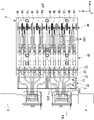
- FIG. 3 is an exploded perspective view of the block of the embodiment divided into a plurality of sub-blocks; It is a top view of a device for cell culture of an embodiment.
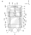
- FIG. 4 is a diagram including the IV-IV section of FIG. 3; 5 is an enlarged view of a pump block of the cell culture device shown in FIG. 4.
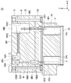
- FIG. 5 is an enlarged view of a tank block of the cell culture device shown in FIG. 4.
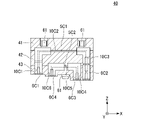
- FIG. 5 is an enlarged view of a connecting block of the cell culture device shown in FIG. 4.
- FIG. It is a top view of the device for cell culture of the 1st modification of embodiment. It is a top view of the device for cell culture of the 2nd modification of embodiment. It is a figure containing the cross section corresponded to FIG. 4 of the device for cell cultures of the 3rd modification of embodiment.
- FIG. 1 is a perspective view of a block 2 that constitutes a cell culture device 1 of an embodiment.
- FIG. 2 is an exploded perspective view of the block 2 of the embodiment divided into a plurality of sub-blocks 20, 30, 40.
- the cell culture device 1 includes a block 2 that is a block-shaped member.
- the block 2 is made of resin such as acrylonitrile, butadiene, styrene copolymer synthetic resin (ABS resin), polycarbonate (PC), or the like.
- an XYZ orthogonal coordinate system is set, and the positional relationship of each member will be explained with reference to this XYZ orthogonal coordinate system.
- a predetermined direction in the horizontal plane is the X direction
- a direction perpendicular to the X direction in the horizontal plane is the Y direction
- a direction perpendicular to the X and Y directions (that is, the vertical direction) is the Z direction.
- the arrow side in the drawing is the plus (+) side
- the opposite side to the arrow is the minus (-) side.
- the +Z side corresponds to the upper side in the vertical direction
- the -Z side corresponds to the lower side in the vertical direction.
- FIG. 3 is a top view of the cell culture device 1 of the embodiment.
- FIG. 4 is a diagram including the IV-IV section of FIG.
- the block 2 has a guide portion 10 to which a pipe 5 capable of circulating a liquid for cell culture sent from the pump 3 (hereinafter also referred to as "culture medium") can be attached and detached.
- the culture medium contains various agents for culturing cells.
- the guide portion 10 includes a concave portion 11 that guides the pipe 5 along the surface of the block 2 and a hole portion 12 that guides the pipe 5 through the inside of the block 2 .
- the concave portion 11 means a portion that guides the pipe 5 along the outer surface (surface) of the block 2 , such as a dent or groove that can be seen from the outside of the block 2 .
- the hole portion 12 means a portion that guides the pipe 5 through the internal space of the block 2 , such as a through hole or space that cannot be seen from the outside of the block 2 .
- the block 2 includes a plurality of (for example, three in this embodiment) sub-blocks 20, 30, and 40 that are detachably divided from each other.
- the three sub-blocks 20 , 30 , 40 are the pump block 20 , the tank block 30 and the connecting block 40 .
- the pump block 20 and the tank block 30 are detachably connected to each other by a fixing member 60 such as a lock pin.
- the connecting block 40 is detachably connected to the pump block 20 and the tank block 30 by means of an uneven structure 50 including concave and convex portions.
- the connection method using the fixing member is not limited to the above, and various methods such as screwing and fixing using a band can be adopted.
- FIG. 5 is an enlarged view of the pump block 20 of the cell culture device 1 shown in FIG.
- the pump block 20 has pump-side guide portions 10A1 to 10A8 (an example of guide portions) to which the pump connection tubes 5A1 to 5A5 constituting the pipe 5 are detachable.
- the pump block 20 has a pump mounting portion 21a on which the pump 3 can be mounted.
- two pump mounting portions 21a are provided with an interval in the Y direction.
- two pumps 3 can be mounted on the pump block 20 .
- the number of installed pumps 3 is not limited to the above, and can be changed according to required specifications.
- the pump block 20 includes a plurality of (eg, five in this embodiment) cassettes 21 to 25 detachably connected to each other.
- the five cassettes 21 to 25 constituting the pump block 20 are a first pump cassette 21, a second pump cassette 22, a third pump cassette 23, a fourth pump cassette 24 and a fifth pump cassette 25.
- the five cassettes 21 to 25 are arranged in the order of the first pump cassette 21, the second pump cassette 22, the third pump cassette 23, the fourth pump cassette 24, and the fifth pump cassette 25 from the -X side to the +X side. ing. It should be noted that the number of installed cassettes constituting the pump block 20 is not limited to the above, and can be changed according to the required specifications.
- the first pump cassette 21 is formed in a U shape that opens to the -X side when viewed from the Y direction.
- the first pump cassette 21 has a pump mounting portion 21a.
- the pump mounting portion 21 a is provided inside the U-shaped opening formed by the first pump cassette 21 .
- each of the second pump cassette 22, the third pump cassette 23, the fourth pump cassette 24, and the fifth pump cassette 25 has a rectangular parallelepiped shape having a long side in the Y direction and a short side in the Z direction. is formed in The second pump cassette 22, the third pump cassette 23, the fourth pump cassette 24, and the fifth pump cassette 25 have the same length in the Y direction.
- the first pump cassette 21 and the second pump cassette 22 are detachably connected to each other by fixing members 60 such as lock pins (two fixing members 60 on the +Z side are shown in FIG. 2).
- the second pump cassette 22 and the third pump cassette 23 are detachably connected to each other by a fixing member 60 such as a lock pin (the fixing member 60 on the -Y side is shown in FIG. 2).
- the third pump cassette 23 and the fifth pump cassette 25 are detachable from each other with a fixing member 60 such as a lock pin (the fixing member 60 on the -Y side is shown in FIG. 2) with the fourth pump cassette 24 sandwiched therebetween. It is connected.
- the first to fifth pump cassettes 21 to 25 are detachably connected to each other by fixing members 61 such as bolts.
- the connection method using the fixing member is not limited to the above, and various methods such as screwing and fixing using a band can be adopted.
- FIG. 6 is an enlarged view of the tank block 30 of the cell culture device 1 shown in FIG.
- the tank block 30 has tank-side guide portions 10B1 to 10B6 (an example of guide portions) to which the relay tubes 5B1 to 5B3 constituting the pipe 5 are detachable.
- the tank block 30 is formed in a rectangular parallelepiped shape having a long side in the Y direction and a short side in the X direction.
- the tank block 30 includes a plurality of (for example, three in this embodiment) cassettes 31 to 33 detachably connected to each other.
- the three cassettes 31 to 33 constituting the tank block 30 are a first tank cassette 31, a second tank cassette 32 and a third tank cassette 33.
- the three cassettes 31 to 33 are arranged in order of the first tank cassette 31, the second tank cassette 32, and the third tank cassette 33 from the +Z side to the -Z side.
- the number of cassettes that constitute the tank block 30 is not limited to the above, and can be changed according to the required specifications.
- the first tank cassette 31, the second tank cassette 32 and the third tank cassette 33 are each formed in a rectangular parallelepiped shape having a long side in the Y direction and a short side in the X direction.
- the first tank cassette 31 , the second tank cassette 32 , and the third tank cassette 33 have the same Y-direction length as the fifth pump cassette 25 .
- the second tank cassette 32 is thicker (length in the Z direction) than each of the first tank cassette 31 and the second tank cassette 32 .
- the first tank cassette 31 and the second tank cassette 32 are detachably connected to each other by a fixing member 60 such as a lock pin (the fixing member 60 on the -Y side is shown in FIG. 2).
- the second tank cassette 32 and the third tank cassette 33 are detachably connected to each other by a fixing member 60 such as a lock pin (the fixing member 60 on the -Y side is shown in FIG. 2).
- the second tank cassette 32 and the fifth pump cassette 25 are detachably connected to each other by a fixing member 60 such as a lock pin (the fixing member 60 on the -Y side is shown in FIG. 1).
- the first tank cassette 31 to the third tank cassette 33 are detachably connected to each other by fixing members 61 such as bolts.
- the connection method using the fixing member is not limited to the above, and various methods such as screwing and fixing using a band can be adopted.
- FIG. 7 is an enlarged view of the connection block 40 of the cell culture device 1 shown in FIG.
- the connection block 40 has connection guide portions 10C1 to 10C6 to which the connection tubes 5C1 to 5C2 are detachable.
- the connection block 40 is formed in a rectangular parallelepiped shape having a long side in the Y direction and a short side in the X direction.
- the connection block 40 and the tank block 30 have the same length in the Y direction.
- the connecting block 40 includes a plurality of (for example, three in this embodiment) cassettes 41 to 43 detachably connected to each other.
- the three cassettes 41 to 43 constituting the connecting block 40 are a first connecting cassette 41, a second connecting cassette 42 and a third connecting cassette 43.
- the three cassettes are arranged from the +Z side to the -Z side in the order of the first linked cassette 41, the second linked cassette 42, and the third linked cassette 43.
- the number of installed cassettes constituting the connection block 40 is not limited to the above, and can be changed according to the required specifications.
- the first connecting cassette 41, the second connecting cassette 42 and the third connecting cassette 43 are each formed in a rectangular parallelepiped shape having a long side in the Y direction and a short side in the X direction.
- the first connecting cassette 41, the second connecting cassette 42 and the third connecting cassette 43 have the same length in the Y direction as the third pump cassette 23, the fourth pump cassette 24 and the fifth pump cassette 25, respectively.
- the first connecting cassette 41 and the second connecting cassette 42 are connected to each other by fixing members 60 such as lock pins (in FIG. 2, three fixing members 60 are shown spaced apart in the Y direction on the ⁇ X side). Detachably connected.
- the second connecting cassette 42 and the third connecting cassette 43 are connected to each other by fixing members 60 such as lock pins (in FIG. 2, three fixing members 60 are shown spaced apart in the Y direction on the ⁇ X side). Detachably connected.
- the first connecting cassette 41 to the third connecting cassette 43 are detachably connected to each other by fixing members 61 such as bolts.
- the connection method using the fixing member is not limited to the above, and various methods such as screwing and fixing using a band can be adopted.
- the third connecting cassette 43 is detachably connected to the pump block 20 and the tank block 30 by means of an uneven structure 50 including recesses and protrusions.
- the concave-convex structure 50 includes a first concave portion 51 provided on the +X side and +Z side portion of the pump block 20, a second concave portion 52 provided on the ⁇ X side and +Z side portion of the tank block 30, A first convex portion 53 provided at a position corresponding to the first concave portion 51 in the third connecting cassette 43, and a second convex portion provided at a position corresponding to the second concave portion 52 in the third connecting cassette 43. a portion 54; It should be noted that the modes of the concave portions and convex portions that constitute the concave-convex structure 50 are not limited to the above, and can be changed according to the required specifications.
- the pipes 5 are arranged inside and outside the block 2 .
- the pipe 5 is made of a material having lower drug adsorption than the block 2 .
- the pipe 5 may be made of polyetheretherketone resin (PEEK resin) or fluororesin (for example, polytetrafluoroethylene, etc.).
- the piping 5 includes a plurality of tubes 5A1-5A5, 5B1-5B3, 5C1-5C2, 5D1-5D2 provided corresponding to the plurality of sub-blocks 20, 30, 40.
- the plurality of tubes 5A1 to 5A5, 5B1 to 5B3, 5C1 to 5C2, 5D1 to 5D2 include pump connection tubes 5A1 to 5A5 connectable to the pump 3, relay tubes 5B1 to 5B3 for relaying piping, and pump connection tubes. It includes connecting tubes 5C1 to 5C2 that can connect 5A1 to 5A5 and relay tubes 5B1 to 5B3, and tank connecting tubes 5D1 to 5D2 that can be connected to the tank 4 that stores the culture solution.
- a plurality of tubes 5A1-5A5, 5B1-5B3, 5C1-5C2, 5D1-5D2 correspond to at least one of a plurality of cassettes 21-25, 31-34, 41-43 constituting sub-blocks 20, 30, 40. is provided.
- a plurality of pump connection tubes 5A1 to 5A5 (in the example of FIG. 4, five for one pump 3) are provided.
- the pump connection tubes 5A1 to 5A5 are arranged downstream of the first pump connection tube 5A1 into which the culture solution sent from the pump 3 flows, and the first pump connection tube 5A1 in the direction W in which the culture solution flows in the pipe 5.
- 5A4 and a fifth pump connection tube 5A5 arranged downstream of the fourth pump connection tube 5A4.
- the number of tubes to be installed constituting the pump connection tubes 5A1 to 5A5 is not limited to the above, and can be changed according to required specifications.
- the first pump connection tube 5A1 extends from the +Z end of the pump 3 to the +Z side, and then extends to the +X side toward the vicinity of the +Z end of the -X end of the first pump cassette 21.
- the second pump connection tube 5A2 extends from the vicinity of the +X end of the first pump connection tube 5A1 toward the +X end of the second pump cassette 22 toward the +X side.
- a plurality of second pump connection tubes 5A2 (in the example of FIG. 3, six for one pump 3) are provided.
- the second pump connection tube 5A2 arranged on the outermost side in the Y direction among the six tubes in the top view of FIG. It extends and then extends to the +X side.
- the second pump connection tube 5A2 which is the second outermost in the Y direction among the six, is arranged from a portion inside the outermost second pump connection tube 5A2 in the Y direction in the pump 3. After extending to the +X side, it extends obliquely outward in the Y direction of the second pump cassette 22, and then extends to the +X side.
- the second pump connection tube 5A2 arranged innermost in the Y direction among the six tubes is arranged from a portion inside in the Y direction of the second outer second pump connection tube 5A2 in the pump 3. After extending to the +X side, it extends outward in the Y direction of the second pump cassette 22 with a gentler inclination than the second outer second pump connection tube 5A2, and then extends to the +X side.
- the third pump connection tube 5A3 extends inside the fifth pump cassette 25 from near the +Z end of the fifth pump cassette 25 to the -Z side.
- the fourth pump connection tube 5A4 extends inside the first pump cassette 21 toward the -X side from the vicinity of the -Z end of the +X end of the first pump cassette 21.
- the fifth pump connection tube 5A5 extends from the vicinity of the ⁇ X end of the first pump cassette 21 toward the ⁇ Z end toward the ⁇ X side, and then toward the ⁇ Z end of the pump 3 toward the +Z side. ing.
- a plurality (three in the example of FIG. 4) of the relay tubes 5B1 to 5B3 are provided.
- the relay tubes 5B1 to 5B3 are arranged downstream of the first relay tube 5B1 and the first relay tube 5B1 arranged downstream of the second pump connection tube 5A2 in the direction W in which the culture solution flows in the pipe 5. and a third relay tube 5B3 disposed downstream of the second relay tube 5B2.
- the number of tubes that constitute the relay tubes 5B1 to 5B3 is not limited to the above, and can be changed according to the required specifications.
- first relay tubes 5B1 for example, six in this embodiment corresponding to the second pump connection tubes 5A2 are provided.
- the first pump connection tube 5A1 extends inside the tank block 30 in the X direction.
- the first relay tube 5B1 extends from the -X side of the +Z end of the second tank cassette 32 to the +X side.
- the second relay tube 5B2 extends toward the one tank 4 from the downstream side of the +X end of the first relay tube 5B1 toward the ⁇ Z side.
- the third relay tube 5B3 is located at the +Z end of the second tank cassette 32 from the same Z direction position as the downstream end of the second relay tube 5B2, than the -X end of the first relay tube 5B1. It extends to the +Z side toward the X side portion.
- connection tubes 5C1 and 5C2 are arranged between the first connection tube 5C1 and the third relay tube 5B3, which are arranged between the first pump connection tube 5A1 and the first relay tube 5B1 in the direction W in which the culture solution flows in the pipe 5. and a second connecting tube 5C2 arranged between the third pump connecting tube 5A3.
- a plurality of first connection tubes 5C1 may be provided corresponding to the first pump connection tubes 5A1.
- the number of tubes constituting the connecting tubes 5C1 to 5C2 is not limited to the above, and can be changed according to required specifications.
- the first connection tube 5C1 extends in the X direction on the +Z end side of the second connection cassette 42.
- the second connection tube 5C2 extends in the X direction on the +Z end side of the third connection cassette 43.
- the X-direction length of the second connection tube 5C2 is smaller than the X-direction length of the first connection tube 5C1.
- the tank connection tubes 5D1 and 5D2 are a first tank connection tube 5D1 arranged downstream of the second relay tube 5B2 in the direction W in which the culture solution flows in the pipe 5, the first tank connection tube 5D1, and the third relay tube. and a second tank connection tube 5D2 arranged between 5B3.
- a plurality of first tank connection tubes 5D1 may be provided corresponding to one of the tanks 4 .
- a plurality of second tank connection tubes 5D2 may be provided corresponding to the other tank 4 (the tank 4 arranged on the -X side of the one tank 4).
- the number of tubes constituting the tank connection tubes 5D1 and 5D2 is not limited to the above, and can be changed according to required specifications.
- the first tank connection tube 5D1 extends from the vicinity of the -Z end of the second relay tube 5B2 toward the interior of one of the tanks 4 toward the -Z side.
- the second tank connection tube 5D2 extends from the inside of the other tank 4 toward the -X side inside the third tank cassette 33 toward the +Z side.
- the cell culture device 1 may include joint members 6 detachably connected to the tubes 5A1-5A5, 5B1-5B3, 5C1-5C2.
- the joint member 6 is made of a material having lower drug adsorption than the block 2 .
- the joint member 6 may be made of polyetheretherketone resin (PEEK resin), fluororesin (for example, polytetrafluoroethylene, etc.), fluororubber, or the like. good.
- the joint members 6 are provided at portions of the plurality of sub-blocks 20, 30, 40 that are connected to each other.
- the joint member 6 is provided at a portion where the plurality of cassettes 21-25, 31-34, 41-43 constituting the sub-blocks 20, 30, 40 are connected to each other.
- a plurality of joint members 6 are provided.
- the plurality of joint members 6 include joint tubes (an example of tubes).
- the plurality of joint members 6 are formed in various shapes such as a shape extending in one direction, an L shape, and a block shape.
- the plurality of joint members 6 includes a plurality of (five in the example of FIG. 4) pump joint tubes 6A1 to 6A5 detachably connected to the pump connection tubes 5A1 to 5A5, and the relay tubes 5B1 to 5B3.
- the five pump joint tubes 6A1 to 6A5 are a first pump joint tube 6A1 detachably connected to the +Z end side of the first pump cassette 21, and a second pump joint tube 6A1 from the second pump cassette 22 to the A second pump joint tube 6A2 detachably connected to the 4-pump cassette 24; a third pump joint tube 6A3 detachably connected to the fourth pump cassette 24 and the fifth pump cassette 25; A fourth pump joint tube 6A4 detachably connected from the second pump cassette 22 to the fifth pump cassette 25, and a fifth pump joint detachably connected to the -Z end side of the first pump cassette 21. and a tube 6A5.
- the number of tubes to be installed constituting the pump joint tubes 6A1 to 6A5 is not limited to the above, and can be changed according to required specifications.
- the first pump joint tube 6A1 extends in the X direction. 4, the first pump joint tube 6A1 has a -X end connected to the +X end of the first pump connection tube 5A1 and a +X end connected to the -X end of the second pump connection tube 5A2. .
- the second pump joint tube 6A2 is formed in an L shape in the cross-sectional view of FIG. 4, the second pump joint tube 6A2 has a ⁇ X end connected to the +X end of the second pump connection tube 5A2 and a +Z end arranged on the +Z end side of the third pump cassette 23. As shown in FIG. In addition, the second joint tube may include a plurality of joint tubes detachably connected to each other.
- the third pump joint tube 6A3 extends in the Z direction. 4, the third pump joint tube 6A3 has a ⁇ Z end connected to the +Z end of the third pump connection tube 5A3 and a +Z end arranged on the +Z end side of the fifth pump cassette 25. As shown in FIG.
- the fourth pump joint tube 6A4 is formed in an L shape. 4, the length of the fourth pump joint tube 6A4 in the X direction is greater than the length of the second pump joint tube 6A2 in the X direction. 4, the fourth pump joint tube 6A4 has a +Z end connected to the ⁇ Z end of the third pump connection tube 5A3 and a ⁇ X end connected to the +X end of the fourth pump connection tube 5A4. .
- the fourth pump joint tube 6A4 may include a plurality of joint tubes detachably connected to each other.
- the fifth pump joint tube 6A5 extends in the X direction parallel to the first pump joint tube 6A1.
- the fifth pump joint tube 6A5 has a +X end connected to the ⁇ X end of the fourth pump connection tube 5A4 and a ⁇ X end connected to the +X end of the fifth pump connection tube 5A5. .
- the four relay joint tubes 6B1 to 6B4 are a first relay joint tube 6B1 detachably connected to the -X end side of the first tank cassette 31 and the second tank cassette 32,
- the second relay joint tube 6B2 detachably connected from the first tank cassette 31 to the +X end side of the third tank cassette 33, and the -X end side of the second tank cassette 32 and the third tank cassette 33
- the third relay joint tube 6B3 detachably connected to the second tank cassette 31 and the -X end side of the first tank cassette 31 and the second tank cassette 32 can be attached to and detached from the -X side portion of the first relay joint tube 6B1.
- a fourth relay joint tube 6B4 connected to the .
- the number of tubes that constitute the relay joint tubes 6B1 to 6B4 is not limited to the above, and can be changed according to required specifications.
- the first relay joint tube 6B1 is formed in an L shape. 4, the first relay joint tube 6B1 has a +Z end arranged on the +Z end side of the first tank cassette 31 and a +X end connected to the -X end of the first relay tube 5B1.
- the second relay joint tube 6B2 is formed in a block shape extending in the Z direction.
- the second relay joint tube 6B2 is arranged on the -X end side connected to the +X end of the first relay tube 5B1 and the +X end side on the -Z end side of the third tank cassette 33-. It has a Z end (in other words, a ⁇ Z end connected to the +Z end of the first tank connection tube 5D1).
- the second relay joint tube 6B2 preferably includes a plurality of joint tubes detachably connected to each other.
- the third relay joint tube 6B3 extends in the Z direction. 4, the third relay joint tube 6B3 has a -Z end connected to the +Z end of the second tank connection tube 5D2 and a +Z end connected to the -Z end of the third relay tube 5B3.
- the fourth relay joint tube 6B4 extends in the Z direction.
- the fourth relay joint tube 6B4 is connected to the +Z end of the third relay tube 5B3, and the +Z end of the first tank cassette 31 is closer to the -Z end than the first relay joint tube 6B1. It has a +Z edge located on the X side.
- the four connecting joint tubes 6C1 to 6C4 are detachably connected from the first connecting cassette 41 to the -X end side of the third connecting cassette 43, the first connecting joint tube 6C1,
- the second connection joint tube 6C2 detachably connected from the first connection cassette 41 to the +X end side of the third connection cassette 43, and the +X end side of the second connection cassette 42 and the third connection cassette 43
- a detachably connected third connection joint tube 6C3 and a fourth connection joint tube 6C4 detachably connected to the -X end sides of the second connection cassette 42 and the third connection cassette 43 are included.
- the number of tubes that constitute the connecting joint tubes 6C1 to 6C4 is not limited to the above, and can be changed according to required specifications.
- the first connecting joint tube 6C1 is formed in an L shape as viewed in cross section in FIG. 4, the first connection joint tube 6C1 has a -Z end connected to the +Z end of the second pump joint tube 6A2 and a +X end connected to the -X end of the first connection tube 5C1.
- the first connection joint tube 6C1 may include a plurality of joint tubes detachably connected to each other.
- the second connecting joint tube 6C2 is formed in an L shape in the cross-sectional view of FIG. 4, the second connecting joint tube 6C2 has a ⁇ X end connected to the +X end of the first connecting tube 5C1 and a ⁇ Z end connected to the +Z end of the first relay joint tube 6B1.
- the second connection joint tube 6C2 may include a plurality of joint tubes detachably connected to each other.
- the third connection joint tube 6C3 is formed in an L shape.
- the Z-direction length of the third connection joint tube 6C3 is smaller than the Z-direction length of the second connection joint tube 6C2.
- the third connection joint tube 6C3 has a ⁇ Z end connected to the +Z end of the third relay tube 5B3 and a ⁇ X end connected to the +X end of the second connection tube 5C2.
- the fourth connection joint tube 6C4 is formed in an L shape as viewed in cross section in FIG. In the cross-sectional view of FIG. 4, the Z-direction length of the fourth connection joint tube 6C4 is smaller than the Z-direction length of the third connection joint tube 6C3. 4, the fourth connection joint tube 6C4 has a +X end connected to the -X end of the second connection tube 5C2 and a -Z end connected to the +Z end of the third pump joint tube 6A3.
- the guide portion 10 is provided at a portion of the block 2 corresponding to the pipe 5 and the joint member 6 . 4, the guide portion 10 includes pump-side guide portions 10A1 to 10A8 (see FIG. 5) provided in the pump block 20 and relay guide portions 10B1 to 10B6 (see FIG. 6) provided in the tank block 30. ), and connection guide portions 10C1 to 10C6 provided in the connection block 40 (see FIG. 7).
- the pump-side guide portions 10A1 to 10A8 include a first pump-side guide portion 10A1 to which the first pump joint tube 6A1 is detachable, and a second pump-side guide portion to which the second pump connection tube 5A2 is detachable.
- a portion 10A2 a third pump side guide portion 10A3 to which the second pump joint tube 6A2 is detachable, a fourth pump side guide portion 10A4 to which the third pump joint tube 6A3 is detachable, and a third pump connection tube 5A3.
- a sixth pump-side guide portion 10A6 to which the fourth pump joint tube 6A4 is detachable; a seventh pump-side guide portion 10A7 to which the fourth pump connection tube 5A4 is detachable; and an eighth pump-side guide portion 10A8 to which the 5-pump joint tube 6A5 is detachable.
- the number of guide portions that constitute the pump-side guide portions 10A1 to 10A8 is not limited to the above, and can be changed according to required specifications.
- the pump-side guide portions 10A1 to 10A8 include recesses 11 for guiding the pump joint tubes 6A1 to 6A5 and the pump connection tubes 5A1 to 5A5 along the surfaces of the pump cassettes 21 to 25, and the pump joint tubes 6A1 to 6A5 and the pump connection tubes 5A1. 5A5 through the interior of the pump cassettes 21-25.
- the first pump-side guide portion 10A1 includes a through hole extending in the Y direction when viewed from the X direction.
- the second pump-side guide portion 10A2 includes a rectangular concave portion 11 recessed from the +Z surface of the first pump cassette 21 toward the ⁇ Z side when viewed from the X direction.
- the third pump-side guide portion 10A3 includes a plurality of (in the example of FIG. 1, six holes spaced apart in the Y direction) circular through holes when viewed from the X direction. 5, the third pump-side guide portion 10A3 includes an L-shaped through hole penetrating from the second pump cassette 22 to the +Z end side of the fourth pump cassette 24. As shown in FIG.
- the fourth pump-side guide portion 10A4 is an opening that opens the +Z end side of the fourth pump cassette 24 and the fifth pump cassette 25 (in other words, the fourth pump cassette 24 and the fifth pump cassette 24). 25) containing grooves extending in the Z direction along the interface.
- the fifth pump-side guide portion 10A5 includes a groove extending in the Z direction along the ⁇ X end face (an example of the surface) of the fifth pump cassette 25.
- the sixth pump-side guide portion 10A6 includes an L-shaped through hole penetrating from the second pump cassette 22 to the fifth pump cassette 25 on the -Z end side.
- the seventh pump-side guide portion 10A7 includes a through-hole penetrating the inside of the -Z end side of the first pump cassette 21 in the X direction.
- the eighth pump-side guide portion 10A8 includes a through-hole extending in the Y direction parallel to the first pump-side guide portion 10A1 when viewed from the X direction.
- the relay guide portions 10B1 to 10B6 include a first relay guide portion 10B1 to which the first relay joint tube 6B1 is detachable, a second relay guide portion 10B2 to which the first relay tube 5B1 is detachable, A third relay guide portion 10B3 to which the second relay joint tube 6B2 is detachable, a fourth relay guide portion 10B4 to which the third relay joint tube 6B3 is detachable, and a fifth relay guide portion to which the third relay tube 5B3 is detachable. 10B5, and a sixth relay guide portion 10B6 to which the fourth relay joint tube 6B4 is detachable. It should be noted that the number of guide portions to be installed constituting the relay guide portions 10B1 to 10B6 is not limited to the above, and can be changed according to required specifications.
- the relay guide portions 10B1 to 10B6 include concave portions for guiding the relay joint tubes 6B1 to 6B4 and the relay tubes 5B1 to 5B3 along the surfaces of the tank cassettes 31 to 33, and guide the relay joint tubes 6B1 to 6B4 and the relay tubes 5B1 to 5B3 along the surfaces of the tank cassettes 31 to 33. and holes guiding through the interior of the cassettes 31-33.
- the first relay guide portion 10B1 includes an L-shaped opening that opens the inside of the first tank cassette 31 and the second tank cassette 32 on the -X end side.
- the second relay guide portion 10B2 includes a groove extending in the X direction along the +Z end surface (an example of the surface) of the second tank cassette 32.
- the third relay guide portion 10B3 includes a rectangular opening recessed from the +Z surface of the first tank cassette 31 toward the ⁇ Z side when viewed from the Z direction.
- the third relay guide portion 10B3 includes a through hole penetrating from the first tank cassette 31 to the +X end side of the third tank cassette 33 in the Z direction.
- the fourth relay guide portion 10B4 includes an opening that opens the inside of the -X end side of the second tank cassette 32 and the third tank cassette 33 in the Z direction.
- the fifth relay guide portion 10B5 includes an opening that opens the inside of the second tank cassette 32 on the -X end side in the Z direction.
- the sixth relay guide portion 10B6 opens in the Z direction on the -X side of the first relay guide portion 10B1 inside the -X end side of the first tank cassette 31 and the second tank cassette 32. including openings for
- connection guide portions 10C1 to 10C6 include a first connection guide portion 10C1 to which the first connection joint tube 6C1 is detachable, a second connection guide portion 10C2 to which the first connection tube 5C1 is detachable, A third connection guide portion 10C3 to which the second connection joint tube 6C2 is detachable, a fourth connection guide portion 10C4 to which the third connection joint tube 6C3 is detachable, and a fifth connection guide portion to which the second connection tube 5C2 is detachable. 10C5, and a sixth connection guide portion 10C6 to which the fourth connection joint tube 6C4 is detachable. It should be noted that the number of guide portions that constitute the connecting guide portions 10C1 to 10C6 is not limited to the above, and can be changed according to required specifications.
- connection guide portions 10C1 to 10C6 connect the connection joint tubes 6C1 to 6C4 and the connection tubes 5C1 to 5C2 with concave portions that guide the connection joint tubes 6C1 to 6C4 and the connection tubes 5C1 to 5C2 along the surfaces of the connection cassettes 41 to 43. and a hole guiding through the interior of the cassettes 41-43.
- the first connection guide portion 10C1 includes an L-shaped opening that opens the inside of the -X end side of the first connection cassette 41 to the third connection cassette 43.
- the second connection guide portion 10C2 includes a groove extending in the X direction along the +Z end surface (an example of the surface) of the second connection cassette 42.
- the third connection guide portion 10C3 includes an L-shaped opening that opens the inside of the first connection cassette 41 to the +X end side of the third connection cassette 43.
- the fourth connection guide portion 10C4 is an L-shaped opening on the -X side of the third connection guide portion 10C3 inside the +X end side of the second connection cassette 42 and the third connection cassette 43.
- the fifth connection guide portion 10C5 includes a groove extending in the X direction along the +Z end surface (an example of the surface) of the third connection cassette 43.
- the sixth connection guide portion 10C6 is located between the first connection guide portion 10C1 and the fifth connection guide portion 10C5 inside the -X end side of the second connection cassette 42 and the third connection cassette 43. includes an L-shaped opening that opens to the
- a supply cassette 34 may be attached to the tank block 30 as shown in FIG.
- the supply cassette 34 includes supply guide portions 10D1 to 10D2 (an example of the guide portion) to which the tank connection tubes 5D1 and 5D2 (an example of a supply pipe capable of supplying the culture solution) can be detachably attached to the culture chip 35 capable of storing the culture solution. ).
- the culture chip 35 has channels for culturing cells.
- the supply cassette 34 is detachably connected to the third tank cassette 33 .
- the supply cassette 34 is detachably connected to the top (+Z end) of the culture chip 35 .
- the supply cassette 34 has a tank mounting portion 34a on which the tank 4 can be mounted.
- a plurality (two in the example of FIG. 6) of the tank mounting portions 34a are provided inside the supply cassette 34 corresponding to a plurality of (two in the example of FIG. 6) of the tanks 4 .
- the number of installed tanks 4 is not limited to the above, and can be changed according to required specifications.
- the supply guide portions 10D1 and 10D2 are composed of a first supply guide portion 10D1 in which one supply pipe (first tank connection tube 5D1) is detachable, and a second supply guide portion 10D1 in which the other supply pipe (second tank connection tube 5D2) is detachable. and a supply guide portion 10D2. It should be noted that the number of guide portions that constitute the supply guide portions 10D1 and 10D2 is not limited to the above, and can be changed according to required specifications.
- the supply guide portions 10D1 and 10D2 include holes for guiding the tank connection tubes 5D1 and 5D2 through the inside of the supply cassette .
- the first supply guide portion 10D1 includes a through hole that opens in the Z direction on the +X end side of the wall portion of the supply cassette 34 on the +Z end side.
- the second supply guide portion 10D2 includes a through hole that opens in the Z direction on the ⁇ X end side of the +Z end side wall portion of the supply cassette 34 .
- the cell culture device 1 has different pipe connection systems 9A to 9F and 9G to 9L depending on the purpose of cell culture.
- the pipe connection systems 9A to 9F and 9G to 9L are composed of first pipe connection systems 9A to 9F connected to one pump 3, second pipe connection systems 9G to 9L connected to the other pump 3, including.
- the first pipe connection systems 9A to 9F are arranged on the -Y side of the block 2.
- the first piping connection system 9A-9F includes piping 5 through which the first culture solution flows (in the example of FIG. 3, six tubes 9A-9F extending from the pump 3 on the -Y side).
- the second pipe connection systems 9G to 9L are arranged on the +Y side of the block 2 .
- the second piping connection system 9G-9L includes piping 5 through which the second culture fluid flows (in the example of FIG. 3, six tubes 9G-9L extending from the +Y side pump 3).
- the second culture medium may be a different liquid than the first culture medium.
- connection order of the cassettes 21-25, 31-34, 41-43 and the sub-blocks 20, 30, 40, the mounting order of the pump 3 and the tank 4, and the tubes 5A1 5A5, 5B1 to 5B3, 5C1 to 5C2, 5D1 to 5D2, 6A1 to 6A5, 6B1 to 6A4, and 6C1 to 6C4 are not limited, and can be changed as necessary.
- the first pump connection tube 5A1, the first pump joint tube 6A1, the second pump connection tube 5A2, the second pump joint tube 6A2, the first connection joint tube 6C1, the first connection Tube 5C1, second connecting joint tube 6C2, first relay joint tube 6B1, first relay tube 5B1, second relay joint tube 6B2, second relay tube 5B2, first tank connection tube 5D1, one tank 4, culture chip 35 are connected in sequence.
- the other tank 4 Starting from the culture chip 35, the other tank 4, the second tank connection tube 5D2, the third relay tube 5B3, the third relay joint tube 6B3, the third relay tube 5B3, the fourth relay joint tube 6B4, the third connection Joint tube 6C3, second joint tube 5C2, fourth joint tube 6C4, third pump joint tube 6A3, third pump joint tube 5A3, fourth pump joint tube 6A4, fourth pump joint tube 5A4, fifth pump joint tube 6A5, the fifth pump connection tube 5A5, and the pump 3 are connected in this order.
- the culture solution in the other tank 4 is the second tank connection tube 5D2, the third relay tube 5B3, the third relay joint tube 6B3, the third relay tube 5B3, the fourth relay joint tube 6B4, and the third connection joint tube.
- each tube 5A1 to 5A5, 5B1 to 5B3, 5C1 to 5C2, 5D1 to 5D2, 6A1 to 6A5, 6B1 to 6A4, 6C1 to 6C4 forms a circulation path of the culture solution.
- a culture solution recovery unit for recovering the culture solution may be provided in the middle of the circulation path.
- the cell culture device 1 of the present embodiment includes the block 2 having the guide portion 10 to which the pipe 5 capable of circulating the culture solution is detachable. and a hole 12 for guiding the pipe 5 through the interior of the block 2 .
- the pipe 5 through which the culture solution flows is separated from the block 2, even if the pipe 5 is contaminated with the culture solution, it is possible to avoid contamination of the block 2. and the block 2 can be reused in terms of cost.
- contamination can be suppressed by removing the pipe 5 from the guide portion 10 of the block 2 and attaching an uncontaminated pipe 5 to the guide portion 10 . Therefore, cost reduction can be achieved and contamination can be suppressed.
- cytotoxicity caused by the culture solution remaining in the pipe 5 can be reduced.
- the pipes 5 when the pipes 5 are attached to the guide portion 10 of the block 2, the pipes 5 can be guided in at least one of the recessed portion 11 of the block 2 and the inside of the block 2, so that the pipes 5 are not complicated and confused. can be suppressed. Therefore, it is possible to prevent improper connection of the pipe 5 and leakage of the culture solution, and prevent excessive use of the culture solution due to excessive length of the pipe 5 .
- the block 2 includes a plurality of first pump cassettes 21 that are detachably connected to each other, and the plurality of first pump cassettes 21 are different pipe connection systems 9A to 9F according to the purpose of cell culture. , 9G to 9L. According to this configuration, since the pipe connection systems 9A to 9F and 9G to 9L can be changed according to the purpose of cell culture, it is possible to provide an optimal device for cell culture.
- the block 2 includes a supply cassette 34 having supply guide portions 10D1 to 10D2 to which supply tubes 5D1 and 5D2 capable of supplying culture fluid to a culture chip 35 capable of storing culture fluid are detachable,
- the supply cassette 34 is detachably connected to the top of the culture chip 35 .
- the supply cassette 34 can be connected to the top of the culture chip 35 when the device is used, and the supply cassette 34 can be removed when the device is not used, which is suitable for managing the supply cassette 34. is.
- connection work can be made more efficient.
- the block 2 is made of resin. With this configuration, the weight can be reduced as compared with the case where the block 2 is made of metal.
- the pipe 5 is made of a material with lower drug adsorption than the block 2 . According to this configuration, it is possible to prevent the drug from remaining in the pipe 5, so that it is possible to provide an optimal device for drug evaluation.
- the block 2 includes a plurality of sub-blocks 20, 30, 40 detachably divided. According to this configuration, the plurality of sub-blocks 20, 30, 40 constituting the block 2 can be made compact. In addition, even if the block 2 is partially contaminated, only the contaminated sub-blocks 20, 30, 40 constituting the block 2 should be discarded, and the rest should be reused. This is suitable for reducing costs and suppressing contamination.
- the pipe 5 includes a plurality of tubes 5A1-5A5, 5B1-5B3, 5C1-5C2, 5D1-5D2 provided corresponding to the plurality of sub-blocks 20, 30, 40.
- FIG. the plurality of tubes 5A1 to 5A5, 5B1 to 5B3, 5C1 to 5C2, and 5D1 to 5D2 constituting the pipe 5 can be made compact.
- the pipe 5 is partially contaminated, only the contaminated tubes 5A1 to 5A5, 5B1 to 5B3, 5C1 to 5C2, and 5D1 to 5D2 constituting the pipe 5 are discarded. However, since the remainder can be reused, it is suitable for cost reduction and suppression of contamination.
- the plurality of tubes 5A1 to 5A5, 5B1 to 5B3, 5C1 to 5C2, 5D1 to 5D2 are pump connection tubes 5A1 to 5A5 connectable to the pump 3, and relay tubes 5B1 to 5B3 for relaying piping.
- a plurality of sub-blocks 20, 30, and 40 are detachably connected to a pump block 20 having pump-side guide portions 10A1 to 10A8 to which pump connection tubes 5A1 to 5A5 can be attached and detached. and a tank block 30 having detachable relay guide portions 10B1 to 10B6 for the relay tubes 5B1 to 5B3.
- the pump block 20 has a pump mounting portion 21a on which the pump 3 can be mounted, and the supply cassette 34 has a tank mounting portion 34a on which the tank 4 can be mounted.
- the pump 3 is mounted on the pump mounting portion 21a and the tank 4 is mounted on the tank mounting portion 34a, and when the device is not used, the pump 3 and the tank 4 can be removed. . Therefore, it is suitable for managing the pump 3 and the tank 4 .
- the plurality of tubes 5A1 to 5A5, 5B1 to 5B3, 5C1 to 5C2, 5D1 to 5D2 include connection tubes 5C1 to 5C2 that can connect the pump connection tubes 5A1 to 5A5 and the relay tubes 5B1 to 5B3,
- the plurality of sub-blocks 20, 30, 40 includes a connection block 40 having connection guide portions 10C1-10C6 to which the connection tubes 5C1-5C2 are detachable. It may be connected as possible. According to this configuration, even if any of the pump connection tubes 5A1 to 5A5, the connection tubes 5C1 to 5C2, and the relay tubes 5B1 to 5B3 are contaminated, only the contaminated ones are discarded and the rest are reused. can do.
- the pump connection tubes 5A1 to 5A5 and the relay tubes 5B1 to 5B3 can be connected directly or can be connected via the connection tubes 5C1 to 5C2, so the degree of freedom in layout of the pipe 5 is improved. .
- the pump block 20 and the tank block 30 can be directly connected or connected via the connection block 40, the layout flexibility of the block 2 is improved.
- the plurality of sub-blocks 20, 30, 40 includes a plurality of cassettes 21-25, 31-34, 41-43 that are detachably connected to each other, and the pipe 5 connects the plurality of cassettes 21-25. , 31 to 34 and 41 to 43, including a plurality of tubes 5A1 to 5A5, 5B1 to 5B3, 5C1 to 5C2 and 5D1 to 5D2. According to this configuration, the plurality of cassettes 21-25, 31-34, 41-43 constituting the sub-blocks 20, 30, 40 can be made compact.
- the cell culture device 1 is provided in the portions connected to each other in the plurality of sub-blocks 20, 30, 40, and is provided for the tubes 5A1-5A5, 5B1-5B3, 5C1-5C2, 5D1-5D2. It has a joint member 6 that is detachably connected. According to this configuration, the tubes 5A1 to 5A5, 5B1 to 5B3, 5C1 to 5C2, and 5D1 to 5D2 can be easily attached and detached by the joint member 6, so connection errors can be reduced and connection work can be made more efficient. can.
- the cell culture device includes a block having a guide part to which a pipe capable of circulating a culture solution is detachable.
- the guide part includes a recess for guiding the pipe along the surface of the block, a hole guiding through the interior of the block, including but not limited to;
- the guide portion may have only a recess for guiding the pipe along the surface of the block, or may have only a hole for guiding the pipe through the inside of the block.
- the guide portion may include at least one of a recess that guides the pipe along the surface of the block and a hole that guides the pipe through the inside of the block.
- the aspect of the guide portion can be changed according to the required specifications.
- the block includes a plurality of first pump cassettes detachably connected to each other, and the plurality of first pump cassettes have different pipe connection systems depending on the purpose of cell culture.
- the plurality of first pump cassettes may have the same piping connection system as each other depending on the purpose of cell culture.
- the aspect of the piping connection system that a plurality of connection blocks have can be changed according to the required specifications.
- the block includes a supply cassette having a supply guide section to which a supply tube capable of supplying culture fluid can be detachably attached to the culture chip capable of storing the culture fluid, and the supply cassette is located above the culture chip.
- the supply cassette may be connected to the bottom of the culture chip.
- the connection mode of the supply cassette to the culture chip can be changed according to the required specifications.
- the block is made of resin, but it is not limited to this.
- the blocks may be made of metal.
- the block material can be changed according to the required specifications.
- the pipe is made of a material with lower drug adsorption than the block, but it is not limited to this.
- the pipe may be made of a material with higher drug adsorption than the block.
- the material of the piping can be changed according to the required specifications.
- the block includes a plurality of sub-blocks detachably divided into each other, but is not limited to this.
- a block may not contain multiple sub-blocks.
- a block may consist of a single block.
- the block aspect can be changed according to the required specifications.
- the piping includes a plurality of tubes provided corresponding to a plurality of sub-blocks, but is not limited to this.
- multiple tubes may not be provided corresponding to multiple sublocks.
- the piping mode can be changed according to the required specifications.
- the plurality of tubes includes a pump connection tube connectable to a pump and a relay tube for relaying piping, and the plurality of sub-blocks are pump-side guides to which the pump connection tubes are attachable and detachable. and a tank block detachably connected to the pump block and having a relay guide portion to which a relay tube is detachable, but not limited thereto.
- the plurality of tubes includes a tank connection tube connectable to the tank, the plurality of sub-blocks are detachably connected to the pump block, and the tank block has a tank-side guide section to which the tank connection tube is detachable.
- multiple sub-blocks may not include pump blocks and tank blocks.
- the aspect of sub-blocks can be changed according to the required specifications.
- the pump block has a pump mounting portion on which a pump can be mounted
- the supply cassette has a tank mounting portion on which a tank can be mounted
- the pump block may not have a pump mount.
- the supply cassette may not have a tank mount.
- aspects of the pump block and supply cassette can be varied according to required specifications.
- the plurality of tubes includes a connection tube that can connect the pump connection tube and the relay tube, and the plurality of sub-blocks includes a connection block having a connection guide section to which the connection tube can be attached and detached.
- the block is detachably connected to the pump block and the tank block, but is not limited to this.
- the plurality of tubes includes a connection tube that can connect the pump connection tube and the tank connection tube
- the plurality of sub-blocks includes a connection block having a connection guide section to which the connection tube can be attached and detached
- the connection block includes: It may be detachably connected to the pump block and the tank block.
- the connection block may not be connected to the pump block and tank block.
- the pump block and tank block may be detachably connected to each other without a connection block.
- the connection mode of each block can be changed according to required specifications.
- the plurality of sub-blocks includes a plurality of cassettes detachably connected to each other, and the piping includes a plurality of tubes provided corresponding to at least one of the plurality of cassettes.
- the plurality of tubes does not have to correspond to at least one of the plurality of cassettes.
- the piping mode can be changed according to the required specifications.
- the cell culture device includes a joint member that is provided at a portion of the plurality of sub-blocks that are connected to each other and that is detachably connected to the tube, but the present invention is not limited to this.
- the cell culture device may not have joint members.
- the tubes may be connected without a joint member.
- the tube connection mode can be changed according to the required specifications.
- connection block 140 is arranged above the pump block and the tank block (+Z side portion), but this is not the only option.
- connection block 140 may be positioned between pump block 120 and tank block 130 in the X direction.
- the layout of the connecting blocks can be changed according to the required specifications.
- the plurality of first pump cassettes have different pipe connection systems depending on the purpose of cell culture, but the present invention is not limited to this.
- a plurality of connection blocks 140, 240 may have different pipe connection systems 109A-109F, 209A-209F depending on the purpose of cell culture.
- the pipe connection systems 109A to 109F and 209A to 209F are the first pipe connection systems 109A to 109F (see FIG. 8) provided in the first connection block 140 and the second connection block 240 provided. and a second plumbing connection system 209A-209F.
- FIG. 8 a plurality of connection blocks 140, 240 may have different pipe connection systems 109A-109F, 209A-209F depending on the purpose of cell culture.
- the pipe connection systems 109A to 109F and 209A to 209F are the first pipe connection systems 109A to 109F (see FIG. 8) provided in the first connection block 140 and the second connection block 240 provided. and a second plumbing connection system 209A-209F.
- the culture medium flows through the pump block 120, the first connecting block 140 and the tank block 130. flow through the tubes 109A to 109F guided by the guide portions of the .
- the second connection block 240 is arranged between the pump block 120 and the tank block 130 as shown in FIG. flow through the tubes 209A to 209F guided by the guide portions of the .
- the second pipe connection systems 209A-209F intersect three-dimensionally inside the second connecting block 240.
- FIG. the aspect of the piping connection system can be changed according to the required specifications.
- the supply cassette has a tank mounting portion on which a tank can be mounted, but the present invention is not limited to this.
- the tank block 330 may have a tank mounting portion 334a on which the tank 4 can be mounted.
- the same reference numerals are given to the same configurations as in the above-described embodiment, and some of the pipe components are omitted.
- the tank block 330 may not have a supply cassette attached.
- the culture chip 35 may be attached to the bottom of the third tank cassette 33 .
- the arrangement of supply cassettes and culture chips can be changed according to required specifications.
- a cell culture device for culturing cells by circulating a cell culture liquid has been described, but the present invention is not limited to this.
- the present invention may be applied to other fluid circuit devices such as a liquid delivery device for circulating liquids other than those for cell culture, and an air delivery device for circulating gas.
- a fluid circuit device according to an aspect of the present invention includes a block having a guide portion to which a pipe capable of circulating fluid sent from a pump is attachable and detachable, and the guide portion guides the pipe along the surface of the block. and/or a hole for guiding the pipe through the interior of the block.
- the block since the pipe through which the fluid flows is separated from the block, even if the pipe is contaminated with the fluid, the block can be prevented from being contaminated, and the block can be saved in terms of cost. can be reused.
- contamination can be suppressed by removing the piping from the guide portion of the block and attaching uncontaminated piping to the guide portion. Therefore, cost reduction can be achieved and contamination can be suppressed.
- the pipes when the pipes are attached to the guide portion of the block, the pipes can be guided in at least one of the concave portion of the block and the inside of the block. Therefore, it is possible to prevent improper connection of pipes and leakage of fluid, and prevent excessive use of fluid due to excessive length of pipes.
- Relay guide part 10C1-10C6 ... Connection guide part 10D1 10D2... Supply guide portion 11... Recess 12... Hole 20, 120... Pump block (sub-block) 21-25... Pump cassette (cassette) 21a... Pump mounting part 30, 130, 330... Tank block (sub-block) 31 ⁇ 33... Tank cassette (cassette) 34... Supply cassette (cassette) 34a, 334a... Tank mounting part 35... Culture chip 40, 140, 240... Connection block 41-43... Connection cassette (cassette)
Landscapes
- Health & Medical Sciences (AREA)
- Chemical & Material Sciences (AREA)
- Wood Science & Technology (AREA)
- Organic Chemistry (AREA)
- Life Sciences & Earth Sciences (AREA)
- Engineering & Computer Science (AREA)
- Bioinformatics & Cheminformatics (AREA)
- Zoology (AREA)
- Biomedical Technology (AREA)
- Sustainable Development (AREA)
- Microbiology (AREA)
- Biotechnology (AREA)
- Biochemistry (AREA)
- General Engineering & Computer Science (AREA)
- General Health & Medical Sciences (AREA)
- Genetics & Genomics (AREA)
- Clinical Laboratory Science (AREA)
- Dispersion Chemistry (AREA)
- Immunology (AREA)
- Apparatus Associated With Microorganisms And Enzymes (AREA)
Priority Applications (4)
| Application Number | Priority Date | Filing Date | Title |
|---|---|---|---|
| JP2023505159A JPWO2022190627A1 (https=) | 2021-03-09 | 2022-01-14 | |
| EP22766595.7A EP4306632A1 (en) | 2021-03-09 | 2022-01-14 | Fluid circuit device and cell culture device |
| US18/547,088 US20240124823A1 (en) | 2021-03-09 | 2022-01-14 | Fluid circuit device and cell culture device |
| CN202280019655.6A CN116940664A (zh) | 2021-03-09 | 2022-01-14 | 流体回路器具及细胞培养用器具 |
Applications Claiming Priority (2)
| Application Number | Priority Date | Filing Date | Title |
|---|---|---|---|
| JP2021-037414 | 2021-03-09 | ||
| JP2021037414 | 2021-03-09 |
Publications (1)
| Publication Number | Publication Date |
|---|---|
| WO2022190627A1 true WO2022190627A1 (ja) | 2022-09-15 |
Family
ID=83226626
Family Applications (1)
| Application Number | Title | Priority Date | Filing Date |
|---|---|---|---|
| PCT/JP2022/001245 Ceased WO2022190627A1 (ja) | 2021-03-09 | 2022-01-14 | 流体回路デバイス及び細胞培養用デバイス |
Country Status (5)
| Country | Link |
|---|---|
| US (1) | US20240124823A1 (https=) |
| EP (1) | EP4306632A1 (https=) |
| JP (1) | JPWO2022190627A1 (https=) |
| CN (1) | CN116940664A (https=) |
| WO (1) | WO2022190627A1 (https=) |
Cited By (1)
| Publication number | Priority date | Publication date | Assignee | Title |
|---|---|---|---|---|
| WO2024150805A1 (ja) | 2023-01-12 | 2024-07-18 | 東京応化工業株式会社 | チューブ及び細胞培養用デバイス |
Citations (5)
| Publication number | Priority date | Publication date | Assignee | Title |
|---|---|---|---|---|
| JP2015123028A (ja) | 2013-12-27 | 2015-07-06 | コバレントマテリアル株式会社 | 細胞培養モジュール及び細胞培養方法 |
| JP2015186474A (ja) | 2014-03-13 | 2015-10-29 | アークレイ株式会社 | 細胞培養方法、細胞培養部材、及び細胞培養装置 |
| JP2018038339A (ja) * | 2016-09-08 | 2018-03-15 | 株式会社日立製作所 | 細胞分離装置および培養装置 |
| WO2018070264A1 (ja) * | 2016-10-13 | 2018-04-19 | パナソニックIpマネジメント株式会社 | 液体吐出装置と液体吐出装置を有する検査装置、液体吐出装置を有する細胞培養装置 |
| JP2021037414A (ja) | 2020-12-11 | 2021-03-11 | 株式会社三洋物産 | 遊技機 |
Family Cites Families (2)
| Publication number | Priority date | Publication date | Assignee | Title |
|---|---|---|---|---|
| US7919307B2 (en) * | 2005-05-09 | 2011-04-05 | Alpha Plan Gmbh | Supply system for cell culture module |
| CN103881911B (zh) * | 2014-03-25 | 2015-09-09 | 广州中国科学院先进技术研究所 | 一种细胞培养与实验装置 |
-
2022
- 2022-01-14 US US18/547,088 patent/US20240124823A1/en active Pending
- 2022-01-14 JP JP2023505159A patent/JPWO2022190627A1/ja active Pending
- 2022-01-14 CN CN202280019655.6A patent/CN116940664A/zh active Pending
- 2022-01-14 WO PCT/JP2022/001245 patent/WO2022190627A1/ja not_active Ceased
- 2022-01-14 EP EP22766595.7A patent/EP4306632A1/en active Pending
Patent Citations (5)
| Publication number | Priority date | Publication date | Assignee | Title |
|---|---|---|---|---|
| JP2015123028A (ja) | 2013-12-27 | 2015-07-06 | コバレントマテリアル株式会社 | 細胞培養モジュール及び細胞培養方法 |
| JP2015186474A (ja) | 2014-03-13 | 2015-10-29 | アークレイ株式会社 | 細胞培養方法、細胞培養部材、及び細胞培養装置 |
| JP2018038339A (ja) * | 2016-09-08 | 2018-03-15 | 株式会社日立製作所 | 細胞分離装置および培養装置 |
| WO2018070264A1 (ja) * | 2016-10-13 | 2018-04-19 | パナソニックIpマネジメント株式会社 | 液体吐出装置と液体吐出装置を有する検査装置、液体吐出装置を有する細胞培養装置 |
| JP2021037414A (ja) | 2020-12-11 | 2021-03-11 | 株式会社三洋物産 | 遊技機 |
Non-Patent Citations (1)
| Title |
|---|
| ANONYMOUS: "Shimadzu Corporation (SIMADZU)/Prominence Series/Liquid Chromatograph (HPLC) (new old) ", SKY SCIENCE CO., LTD., 1 December 2016 (2016-12-01), XP055965179, Retrieved from the Internet <URL:http://sky-go.com/old/島津製作所simadzuprominence> * |
Cited By (2)
| Publication number | Priority date | Publication date | Assignee | Title |
|---|---|---|---|---|
| WO2024150805A1 (ja) | 2023-01-12 | 2024-07-18 | 東京応化工業株式会社 | チューブ及び細胞培養用デバイス |
| EP4650430A1 (en) | 2023-01-12 | 2025-11-19 | Tokyo Ohka Kogyo Co., Ltd. | Tube and cell culture device |
Also Published As
| Publication number | Publication date |
|---|---|
| JPWO2022190627A1 (https=) | 2022-09-15 |
| EP4306632A1 (en) | 2024-01-17 |
| CN116940664A (zh) | 2023-10-24 |
| US20240124823A1 (en) | 2024-04-18 |
Similar Documents
| Publication | Publication Date | Title |
|---|---|---|
| TWI597186B (zh) | Liquid storage container | |
| US20200020549A1 (en) | Substrate Storage Container | |
| WO2022190627A1 (ja) | 流体回路デバイス及び細胞培養用デバイス | |
| US20050151801A1 (en) | Ink delivery system apparatus and method | |
| JP5456680B2 (ja) | インク供給システムのフィルタ | |
| JP4647665B2 (ja) | 塗布装置、分散液移動方法 | |
| JP5012109B2 (ja) | 中空糸膜モジュール | |
| EP1256452A1 (en) | Ink tank | |
| WO2005071368A2 (en) | Liquid level detection method and apparatus | |
| BRPI0818050B1 (pt) | método de conexão de um módulo de núcleo a uma impressora de jato de tinta e módulo de núcleo para uma impressora de jato de tinta | |
| WO2005070680A1 (en) | Replaceable ink container for inkjet printer | |
| US11745409B2 (en) | Storage device, ejection-material ejection device, and imprint apparatus | |
| US20050151810A1 (en) | Ink container installation and alignment feature | |
| US20250198822A1 (en) | Dust collection adapter | |
| US20050248646A1 (en) | HEPA filter printhead protection | |
| CN117042866A (zh) | 中空纤维膜组件和除湿加湿装置 | |
| CN118183068B (zh) | 一种清洁装置用水箱 | |
| CN118079177A (zh) | 呼气阀及呼吸机 | |
| CN1266435C (zh) | 流道分支装置 | |
| CN113524915A (zh) | 液体容纳容器 | |
| CN115291488A (zh) | 一种带有防断线连供墨盒的复印机 | |
| CN223112403U (zh) | 一种消泡工具 | |
| CN223586633U (zh) | 具有辅助控制功能的在线主动脱气装置 | |
| JP4741207B2 (ja) | ガスメータ | |
| US20250023068A1 (en) | Hollow fiber membrane cartridge assembly |
Legal Events
| Date | Code | Title | Description |
|---|---|---|---|
| 121 | Ep: the epo has been informed by wipo that ep was designated in this application |
Ref document number: 22766595 Country of ref document: EP Kind code of ref document: A1 |
|
| ENP | Entry into the national phase |
Ref document number: 2023505159 Country of ref document: JP Kind code of ref document: A |
|
| WWE | Wipo information: entry into national phase |
Ref document number: 18547088 Country of ref document: US |
|
| WWE | Wipo information: entry into national phase |
Ref document number: 202280019655.6 Country of ref document: CN |
|
| WWE | Wipo information: entry into national phase |
Ref document number: 2022766595 Country of ref document: EP |
|
| NENP | Non-entry into the national phase |
Ref country code: DE |
|
| ENP | Entry into the national phase |
Ref document number: 2022766595 Country of ref document: EP Effective date: 20231009 |