WO2022190232A1 - ガス絶縁開閉装置 - Google Patents
ガス絶縁開閉装置 Download PDFInfo
- Publication number
- WO2022190232A1 WO2022190232A1 PCT/JP2021/009426 JP2021009426W WO2022190232A1 WO 2022190232 A1 WO2022190232 A1 WO 2022190232A1 JP 2021009426 W JP2021009426 W JP 2021009426W WO 2022190232 A1 WO2022190232 A1 WO 2022190232A1
- Authority
- WO
- WIPO (PCT)
- Prior art keywords
- line
- main
- detachable
- bus
- inter
- Prior art date
- Legal status (The legal status is an assumption and is not a legal conclusion. Google has not performed a legal analysis and makes no representation as to the accuracy of the status listed.)
- Ceased
Links
Images





Classifications
-
- H—ELECTRICITY
- H02—GENERATION; CONVERSION OR DISTRIBUTION OF ELECTRIC POWER
- H02B—BOARDS, SUBSTATIONS OR SWITCHING ARRANGEMENTS FOR THE SUPPLY OR DISTRIBUTION OF ELECTRIC POWER
- H02B13/00—Arrangement of switchgear in which switches are enclosed in, or structurally associated with, a casing, e.g. cubicle
- H02B13/02—Arrangement of switchgear in which switches are enclosed in, or structurally associated with, a casing, e.g. cubicle with metal casing
- H02B13/035—Gas-insulated switchgear
- H02B13/045—Details of casing, e.g. gas tightness
Definitions
- the embodiment of the present invention relates to a gas insulated switchgear.
- Gas-insulated switchgear is used at power plants or substations.
- a gas-insulated switchgear has a pair of main busbars, a plurality of lines connected to the main busbars, inter-line terminals connecting the lines, and inter-bus terminals connecting the busbars.
- an accident such as a short circuit may occur on the main bus bar of the connection part of the line.
- Recovery work from an accident is carried out by stopping all or part of the gas-insulated switchgear and reducing the internal insulating gas to atmospheric pressure.
- a gas-insulated switchgear capable of minimizing the affected area and shortening the recovery time during recovery from an accident.
- JP 2013-183526 A JP-A-2002-142340 JP-A-6-133419
- the problem to be solved by the present invention is to provide a gas-insulated switchgear capable of shortening the restoration time.
- the gas-insulated switchgear of the embodiment has main busbars, lines, inter-line terminals, and inter-main-bus terminals.
- a line is connected to the main bus.
- Interline terminals are located between the main busbars of adjacent lines.
- the inter-main-bus terminals are arranged between adjacent main buses for each line. Of a pair of inter-line terminals adjacent to each other across a line and inter-main-bus terminals corresponding to the lines, any two are detachable devices, and the remaining one is a detachable bus.
- the attachment/detachment device includes an expandable container.
- the detachable busbar has a non-stretchable container.
- FIG. 3 is a front cross-sectional view taken along line III-III of FIG. 2; Sectional drawing of a detachable busbar.
- FIG. 2 is a cross-sectional view of a bellows-type attachment/detachment device; Sectional drawing of a 1st slide type
- FIG. 1 is a plan view of a gas-insulated switchgear according to an embodiment.
- the Z direction is the vertical direction and the +Z direction is the upward direction.
- the X and Y directions are horizontal.
- the Y direction is the extending direction of the main bus 2 and the direction in which the plurality of lines 10a to 10c are arranged.
- the +Y direction is the direction from the first line 10a to the third line 10c.
- the X direction is the extension direction of the line 10 and the direction in which the pair of main buses 2m and 2n are arranged.
- the +X direction is the direction from the first main bus line 2m to the second main bus line 2n.
- An electric circuit of a gas insulated switchgear (GIS) 1 is formed by a conductor and a tank covering the outer periphery of the conductor.
- the conductor is the electrical path inside the tank.
- An insulating gas such as SF6 is sealed inside the tank.
- the electrical paths of the gas-insulated switchgear 1 are separated into a plurality of gas sections by insulating spacers.
- the insulating spacer supports the conductor and partitions the interior of the tank in the axial direction of the conductor.
- the gas-insulated switchgear 1 has a main bus 2 (2m, 2n), lines 10 (10a, 10b, 10c), and inter-line terminals 5 (5a, 5b).
- the main bus line 2 extends in the Y direction.
- a pair of main busbars 2m and 2n are arranged at intervals in the X direction.
- the pair of main busbars 2m and 2n are a first main busbar 2m and a second main busbar 2n.
- Line 10 extends in the X direction.
- a plurality of lines 10a-10c are spaced apart in the Y direction.
- the plurality of lines 10a-10c are a first line 10a, a second line 10b and a third line 10c.
- FIG. 2 is a side view of a gas-insulated switchgear.
- Line 10 is connected to an external power cable or the like via cable head 18 .
- the line 10 is connected to the circuit breaker 8 via the line-side disconnector/grounding switch 13 and the instrument current transformer 11 .
- FIG. 3 is a front cross-sectional view taken along line III-III of FIG. 2.
- FIG. The inter-line terminal 5 enables electrical and mechanical attachment/detachment of the main bus bar 2 between the adjacent lines 10 .
- the inter-line terminals 5 are arranged on the main busbar 2 between adjacent lines 10, as shown in FIGS. Interline terminals 5 separate the main busbar 2 into a plurality of gas sections. A gas section for each line 10 and a gas section for inter-line terminals 5 are formed on the main bus 2 .
- the line-to-line terminal 5 includes a first line-to-line terminal 5a and a second line-to-line terminal 5b.
- the first inter-line terminal 5a is arranged between the first line 10a and the second line 10b.
- the second inter-line terminal 5b is arranged between the second line 10b and the third line 10c.
- the gas-insulated switchgear 1 further includes a disconnecting switch/grounding switch 3 (3m, 3n), a main-bus terminal 4, and a circuit breaker 8.
- the disconnecting switch/grounding switch 3 switches the electric circuit between the main bus 2 and the circuit breaker 8 and grounds the circuit in which no voltage is applied when the circuit is stopped.
- the disconnecting switch/earth switch 3 is formed integrally with the main bus bar 2 .
- a pair of disconnecting switches/grounding switches 3m, 3n are arranged corresponding to a pair of main buses 2m, 2n.
- the pair of disconnecting switch/earth switch 3m, 3n is a first disconnecting switch/earth switch 3m and a second disconnecting switch/earth switch 3n.
- the first disconnecting switch/earth switch 3m is formed integrally with the first main bus 2m.
- the second disconnecting switch/earth switch 3n is formed integrally with the second main bus 2n.
- the inter-main-bus terminal 4 enables electrical and mechanical attachment/detachment between the adjacent disconnecting switches/grounding switches 3 .
- the main inter-bus terminal 4 is arranged between the first disconnecting switch/earthing switch 3m and the second disconnecting switch/earthing switch 3n.
- the first disconnecting switch/earth switch 3m, the main bus terminal 4 and the second disconnecting switch/earth switch 3n are separated into different gas divisions.
- the second disconnecting switch/earth switch 3n is connected to the first disconnecting switch/earth switch 3m via the terminal 4 between the main bus lines.
- the first disconnecting switch/earth switch 3m is connected to the circuit breaker 8 via the instrument current transformer 7 .
- the circuit breaker 8 disconnects the electric circuit between the main bus 2 and the line 10 .
- Line 10 is connected to main bus 2 via circuit breaker 8 .
- the line-to-line terminal 5 and the main-bus line terminal 4 will be described in detail. As described above, the line-to-line terminals 5 and the main-bus line terminals 4 allow electrical and mechanical connection and disconnection of the electric lines.
- the inter-line terminal 5 and the inter-main-bus terminal 4 employ the detachable bus 30 shown in FIG. 4 or the detachable device 40-60 shown in FIGS.
- the detachable bus 30 and the detachable devices 40-60 have detachable conductors 39-69 and containers 31-61 that cover the detachable conductors 39-69.
- the detachable conductors 39-69 can be detached by disassembly and assembly.
- the container 31 of the detachable bus 30 is a tank that does not expand and contract along the axial direction of the detachable conductor 39 .
- the container 41-61 of the attachment/detachment device 40-60 can expand and contract along the axial direction of the attachment/detachment conductor 49-69.
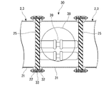
- FIG. 4 is a cross-sectional view of a detachable busbar. 4-7, the axial direction of the detachable conductors 39-69 may be simply referred to as the axial direction (first direction).
- the detachable busbar 30 is adopted as the interline terminal 5 or the main interbus terminal 4 .
- the interline terminals 5 are arranged on the main busbar 2 between adjacent lines 10 .
- the inter-main-bus terminal 4 is arranged between the disconnecting switches/grounding switches 3 adjacent to each other.
- the main bus 2 and the disconnecting switch/grounding switch 3, which are part of the electric circuit of the gas insulated switchgear 1 include a conductor (not shown), a tank 21, and an insulating spacer 25. have.
- the conductor is made of a metal material such as aluminum and is shaped like a round bar.
- the tank 21 is made of a metal material such as aluminum.
- An insulating gas is sealed inside the tank 21 .
- a flange 22 is formed at the end of the tank 21 .
- the insulating spacer 25 is made of an insulating material such as epoxy resin. The insulating spacer 25 supports the conductor and partitions the inside of the tank 21 in the extension direction of the conductor.
- the removable bus 30 has a removable conductor 39 and a container 31 .
- the container 31 is formed in a cylindrical shape from a metal material such as aluminum, and does not expand or contract in the axial direction.
- Flanges 32 are formed at both ends of the container 31 in the axial direction.
- the outer peripheral edge of the insulating spacer 25 is sandwiched between the flange 32 of the container 31 and the flange 22 of the tank 21 .
- the flange 32 , the insulating spacer 25 , and the flange 22 are fastened together (both-fastened) by fastening means 33 such as bolts passing through the three.
- the flange 32 of the container 31 is fixed to the flange 22 of the axially adjacent tank 21 with an insulating spacer 25 interposed therebetween.
- the inside of the container 31 is filled with an insulating gas.
- An openable and closable manhole 38 is formed in the axial center of the container 31 .
- the insulating spacers 25 are arranged at both ends of the detachable busbar 30 in the axial direction.
- the detachable bus 30 and the main bus 2 or the disconnector/grounding switch 3 adjacent to the detachable bus 30 are separated into different gas categories. For example, assume that an accident such as a short circuit occurs inside the main bus 2 on one side of the removable bus 30 . At this time, the insulating gas of the main bus 2 and the removable bus 30 on one side is reduced or atmospheric pressure, but the insulating gas of the main bus 2 on the other side may not be reduced or atmospheric pressure. A differential pressure acts on the insulating spacer 25 between the detachable busbar 30 and the main busbar 2 on the other side.
- the peripheral portion of the insulating spacer 25 is sandwiched between the flange 22 of the main busbar 2 and the flange 32 of the detachable busbar 30 and fastened together.
- the insulating spacer 25 supports the differential pressure of the insulating gas between the main bus 2 and the removable bus 30 .
- the detachable conductor 39 is made of a metal material such as aluminum.
- the detachable conductor 39 is supported by the insulating spacer 25 .
- the detachable conductor 39 is connected to a conductor (not shown) of the main bus 2 or the disconnecting switch/grounding switch 3 adjacent to the detachable bus 30 .
- the detachable conductor 39 can be disassembled in the axial direction.
- the detachable conductor 39 is disassembled starting from the central portion in the axial direction where the manhole 38 is arranged.
- the manhole 38 is opened.
- the detachable conductor 39 is decomposed inside the container 31 and taken out from the manhole 38 .
- the container 31 of the detachable bus 30 is separated from the tank 21 of the main bus 2 or the disconnector/grounding switch 3 in which the accident occurred.
- the main bus 2 or the disconnector/grounding switch 3 adjacent to both sides of the detachable bus 30 are electrically and mechanically separated.
- the attachment/detachment devices 40-60 may be the bellows type attachment/detachment device 40 shown in FIG. 5 or the slide type attachment/detachment devices 50, 60 shown in FIGS.
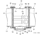
- FIG. 5 is a cross-sectional view of a bellows type attachment/detachment device.
- one axial side (left side of the paper surface) is defined as the r direction, and the other axial side (right side of the paper surface) is defined as the s direction.
- the bellows type attachment/detachment device 40 has an attachment/detachment conductor 49 , a bellows container 41 and a ring 45 .
- the ring 45 is made of a metal material such as aluminum.
- the ring 45 is arranged at the end of the bellows-type attaching/detaching device 40 in the s direction.
- the outer peripheral edge of the insulating spacer 25 is sandwiched between the ring 45 and the flange 22 of the tank 21 adjacent in the s direction.
- the ring 45 , the insulating spacer 25 and the flange 22 are fastened together (both tightened) by means of fastening means 46 such as bolts passing through the three.
- the ring 45 is fixed to the flanges 22 of the tanks 21 adjacent in the s direction with the insulating spacer 25 interposed therebetween.
- the insulating spacer 25 and the ring 45 support the differential pressure of the insulating gas between the tank 21 and the bellows container 41 adjacent in the s direction.
- the bellows container 41 is formed in a bellows shape from a metal material.
- the bellows container 41 can be expanded and contracted in the axial direction by bellows.
- the bellows container 41 has a flange-shaped first member 42r at an end (first end) in the r direction and a second flange-shaped member 42s at an end (second end) in the s direction.
- the outer peripheral edge of the insulating spacer 25 is sandwiched between the r-direction first member 42r and the flange 22 of the tank 21 adjacent in the r-direction.
- the first member 42r, the insulating spacer 25, and the flange 22 are fastened together (both fastened) by fastening means 43 such as bolts passing through the three.
- the first member 42r of the bellows container 41 is fixed to the flanges 22 of the tanks 21 adjacent in the r direction with the insulating spacer 25 interposed therebetween.
- the insulating spacer 25 supports the differential pressure of the insulating gas between the tank 21 and the bellows container 41 adjacent in the r direction.
- the s-direction second member 42 s of the bellows container 41 is attachable to and detachable from the ring 45 .
- An adjustment member 48 for adjusting the distance between the first member 42r and the second member 42s is arranged across the first member 42r and the second member 42s.
- the detachable conductor 49 is made of a metal material such as aluminum.
- the detachable conductor 49 is supported by the insulating spacer 25 .
- the detachable conductor 49 can be disassembled in the axial direction.
- the detachable conductor 49 is disassembled starting from the s-direction end where the gap between the second member 42 s and the ring 45 is formed.
- the second member 42s is removed from the ring 45 after the insulating gas in the bellows-type attaching/detaching device 40 is recovered.
- the bellows container 41 contracts in the r-direction.
- the detachable conductor 49 is decomposed inside the bellows container 41 and taken out through the gap between the second member 42 s and the ring 45 .
- the main busbar 2 or the disconnecting switch/grounding switch 3 adjacent to the bellows type attaching/detaching device 40 is electrically and mechanically separated.
- the slide type attaching/detaching devices 50 and 60 are the first slide type attaching/detaching device 50 shown in FIG. 6, the second slide type attaching/detaching device 60 shown in FIG. 7, or the like.
- FIG. 6 is a cross-sectional view of the first slide-type attachment/detachment device.
- the first slide-type attachment/detachment device 50 has an attachment/detachment conductor 59 , a slide container 51 and a ring 55 .
- the ring 55 is made of a metal material such as aluminum.
- the ring 55 is arranged at the end of the slide type attachment/detachment device 50 in the s direction.
- the outer peripheral edge of the insulating spacer 25 is sandwiched between the ring 55 and the flange 22 of the tank 21 adjacent in the s direction.
- the ring 55 , the insulating spacer 25 , and the flange 22 are fastened together (double-fastened) by fastening means 56 such as bolts passing through the three.
- the ring 55 is fixed to the flanges 22 of the tanks 21 adjacent in the s direction with the insulating spacer 25 interposed therebetween.
- the insulating spacer 25 and the ring 55 support the differential pressure of the insulating gas between the tank 21 and the slide container 51 adjacent in the s direction.
- the slide container 51 is made of a metal material such as aluminum.
- the slide container 51 has a plurality of coaxially arranged sleeves 51r and 51s.
- the radially adjacent sleeves 51r and 51s are in close contact with each other.
- the slide container 51 can be expanded and contracted in the axial direction by a plurality of sleeves 51r and 51s.
- the plurality of sleeves 51r and 51s has a first sleeve 51r in the r direction and a second sleeve 51s in the s direction.
- a first flange 52r is formed at the r-direction end of the first sleeve 51r.
- the outer peripheral edge of the insulating spacer 25 is sandwiched between the first flange 52 r and the flange 22 of the tank 21 .
- the first flange 52r, the insulating spacer 25, and the flange 22 are fastened together (both-fastened) by fastening means 53 such as bolts passing through the three.
- the first flange 52r of the slide container 51 is fixed to the flange 22 of the tank 21 adjacent in the r direction with the insulating spacer 25 interposed therebetween.
- the insulating spacer 25 supports the differential pressure of the insulating gas between the tank 21 and the slide container 51 adjacent in the r direction.
- a second flange 52s is formed at the end of the second sleeve 51s in the s direction.
- the second flange 52s is detachable with respect to the ring 55.
- An adjustment member 58 for adjusting the distance between the first flange 52r and the second flange 52s is arranged across the first flange 52r and the second flange 52s.
- the detachable conductor 59 is made of a metal material such as aluminum.
- the detachable conductor 59 is supported by the insulating spacer 25 .
- the detachable conductor 59 can be disassembled in the axial direction.
- the detachable conductor 59 is disassembled from the detachable connecting portion.
- the second flange 52s is removed from the ring 55 after the insulating gas in the first slide-type attaching/detaching device 50 is recovered.
- the slide container 51 contracts in the r-direction.
- the detachable conductor 59 is disassembled inside the slide container 51 and taken out through the gap between the second flange 52 s and the ring 55 .
- the main busbar 2 or the disconnecting switch/grounding switch 3 adjacent to both sides of the first slide-type attaching/detaching device 50 are separated electrically and mechanically.
- FIG. 7 is a cross-sectional view of the second slide-type attachment/detachment device.
- the second slide-type attachment/detachment device 60 has an attachment/detachment conductor 69 and a slide container 61 .
- the slide container 61 is made of a metal material such as aluminum.
- the slide container 61 has a plurality of coaxially arranged sleeves 61r and 61s.
- the plurality of sleeves 61r and 61s has a first sleeve 61r in the r direction and a second sleeve 61s in the s direction.
- a first flange 62r is formed at the r-direction end of the first sleeve 61r.
- the outer peripheral edge of the insulating spacer 25 is sandwiched between the first flange 62 r and the flange 22 of the tank 21 .
- the first flange 62r, the insulating spacer 25, and the flange 22 are fastened together (both-fastened) by fastening means 63 such as bolts passing through the three.
- the first flange 62r of the slide container 61 is fixed to the flange 22 of the tank 21 adjacent in the r direction with the insulating spacer 25 interposed therebetween.
- the insulating spacer 25 supports the differential pressure of the insulating gas between the tank 21 and the slide container 61 adjacent in the r direction.
- the s-direction end of the slide container 61 is formed in the same manner as the r-direction end.
- a second flange 62s is formed at the end of the second sleeve 61s in the s direction.
- the second flange 62s of the slide container 61 is fixed to the flange 22 of the tank 21 adjacent in the s direction with the insulating spacer 25 interposed therebetween.
- the insulating spacer 25 supports the differential pressure of the insulating gas between the tank 21 and the slide container 61 adjacent in the s direction.
- An adjusting member 68 for adjusting the distance between the first flange 62r and the second flange 62s is arranged across the first flange 62r and the second flange 62s.
- the detachable conductor 69 can be disassembled in the axial direction.
- the detachable conductor 69 can be disassembled starting from each connecting portion. For example, assume that an accident such as a short circuit occurs inside the main bus 2 in the r direction. At this time, the insulating gas in the tank 21 in the r direction and the slide container 61 is reduced to atmospheric pressure. The differential pressure of the insulating gas does not act on the insulating spacers 25 in the r direction. Even if the s-direction tank 21 is not decompressed or atmospheric pressure, the s-direction insulating spacer 25 supports the differential pressure of the insulating gas. The first sleeve 61r is removed from the insulating spacer 25 in the r direction.
- the slide container 61 contracts in the s direction.
- the detachable conductor 69 in the s direction is decomposed inside the slide container 61 and taken out from the gap between the insulating spacer 25 in the r direction and the first flange 62r.
- the above is reversed.
- the second sleeve 61s is removed from the insulating spacer 25 in the s direction.
- the slide container 61 contracts in the r direction.
- the detachable conductor 69 in the r direction is taken out from the gap between the insulating spacer 25 in the s direction and the second flange 62s.
- the main busbar 2 or the disconnecting switch/grounding switch 3 adjacent to both sides of the second slide-type attaching/detaching device 60 are separated electrically and mechanically.
- main bus 2 of the connection portion of the line 10 (hereinafter sometimes referred to as the main bus 2 of the line 10).
- the main bus 2 and the disconnecting switch/grounding switch 3 (hereinafter sometimes referred to as the main bus 2 and the like) at the location of the accident are removed from the gas insulated switchgear 1 .
- the operation of the main bus line 2 and the like is stopped.
- the insulating gas of the main bus line 2 and the like is reduced to the reduced pressure or the atmospheric pressure and recovered.
- the insulating gas of the inter-line terminals 5 and the inter-main-bus terminals 4 adjacent to the main bus 2 and the like is atmospheric pressure.
- the main busbars 2 and the like are electrically and mechanically separated from the gas-insulated switchgear 1 by the inter-line terminals 5 and the inter-main-busbar terminals 4 .
- the main bus 2 and the like are removed by moving in the X direction, Y direction or Z direction. Before the movement of the main generatrix 2 and the like, objects existing in the X direction, the Y direction or the Z direction of the main generatrix 2 and the like are removed in advance.
- the repaired main busbar 2 and the like are attached to the gas insulated switchgear 1 . Specifically, the procedure is reversed to the above.
- FIG. 4 The main bus 2 of the second line 10b where the accident occurred is adjacent to the main bus 2 of the first line 10a and the main bus 2 of the third line 10c via the detachable bus 30 .
- the container 31 (see FIG. 4) of the detachable busbar 30 is a tank that does not expand and contract in the axial direction.
- the attachment/detachment device 40-60 In the gas insulated switchgear 1 of the embodiment, of the pair of inter-line terminals 5 adjacent to each other with the line 10 interposed therebetween, one employs the attachment/detachment device 40-60, and the other employs the attachment/detachment bus 30.
- the detachable busbar 30 is employed for the first inter-line terminal 5a
- the detachable device 40-60 is employed for the second inter-line terminal 5b.
- the attachment/detachment device 40-60 may be employed for the first inter-line terminal 5a
- the attachment/detachment bus 30 may be employed for the second inter-line terminal 5b.
- the bellows type attachment/detachment device 40 is employed as the attachment/detachment device 40-60 will be described below.
- Fig. 8 is an explanatory diagram of the attachment/detachment work of the main busbar, etc.
- the detachable conductor 39 of the detachable bus 30 of the first inter-line terminal 5a is disassembled and taken out.
- the container 31 of the detachable busbar 30 is separated from the tank 21 of the main busbar 2 of the second line 10b.
- the bellows container 41 of the bellows type attachment/detachment device 40 for the second inter-line terminal 5b contracts in the +Y direction.
- the attachment/detachment conductor 49 of the bellows type attachment/detachment device 40 is disassembled and taken out.
- the main busbar 2 of the second line 10b and the like are electrically and mechanically separated from the gas-insulated switchgear 1. As shown in FIG.
- the operation of the main busbar 2 of the first line 10a and the main busbar 2 of the third line 10c is continued during the attaching/detaching work of the main busbar 2 of the second line 10b.
- the insulating gas inside both should not be reduced pressure or atmospheric pressure. As a result, the number of steps of the accident restoration work is reduced, the scope of influence of the work can be minimized, and the restoration time of the gas insulated switchgear 1 is shortened.
- the second main bus 2n of the line 10 is separated from the second main bus 2n of the adjacent line 10 by the inter-line terminal 5 .
- the bellows container 41 of the bellows type attachment/detachment device 40 for the terminal between main busbars 4 contracts in the -X direction.
- the attachment/detachment conductor 49 of the bellows type attachment/detachment device 40 is disassembled and taken out. Thereby, the second main bus 2n and the like are electrically and mechanically separated from the gas-insulated switchgear 1 .
- the second main bus 2n is arranged at the end in the +X direction. Since there is space in the +X direction of the second main bus 2n, it is possible to move the second main bus 2n and the like in the +X direction. As a result, higher safety can be ensured during the attachment/detachment work of the second main bus 2n and the like.
- the operation of the first main bus line 2m and the like is continued during the attaching/detaching work of the second main bus line 2n and the like.
- the insulating gas of the first main bus line 2m and the like is not reduced pressure or atmospheric pressure. As a result, the number of steps of the accident restoration work is reduced, the scope of influence of the work can be minimized, and the restoration time of the gas insulated switchgear 1 is shortened.
- the first main bus 2m of the line 10 is separated from the first main bus 2m of the adjacent line 10 by the inter-line terminal 5 .
- the first main busbars 2m and the like are separated from the adjacent second main busbars 2n and the like by inter-main-busbar terminals 4 .
- the first main bus line 2m and the like are separated from the -X direction objects such as the first main bus line 2m and the like.
- the first main bus 2m and the like are electrically and mechanically separated from the gas-insulated switchgear 1 .
- the insulating gas of the second main bus 2n and the like is not reduced pressure or atmospheric pressure. As a result, the number of steps of the accident restoration work is reduced, the scope of influence of the work can be minimized, and the restoration time of the gas insulated switchgear 1 is shortened.
- the detachable busbar 30 may be employed as the main interbusbar terminal 4.
- FIG. When an accident occurs in the second main bus line 2n, a pair of inter-line terminals 5 and main inter-bus line terminals 4 are attached and detached. In order to remove the second main bus 2n, etc., the line unit installed above the second main bus 2n, etc. is removed, and the +X direction space of the second main bus 2n, etc. is used to remove the second main bus 2n, etc. is possible.
- first main bus line 2m If an accident occurs on the first main bus line 2m, a pair of line inter-line terminals 5 and main bus line inter-terminals 4 will be attached and detached.
- the circuit breaker 8 and instrument current transformer 7 installed in the -X direction of the first main bus line 2m, etc. are removed, and the -X direction space of the first main bus line 2m, etc. is used. It is possible to remove the first main busbar 2m and the like.
- one of the pair of interline terminals 5 adjacent to each other with the line 10 interposed therebetween is the detachable device 40 - 60 and the other is the detachable bus 30 .
- the main inter-bus terminal 4 is a detachable device 40-60.
- both of the pair of inter-line terminals 5 may be the attachment/detachment devices 40 - 60
- the main inter-bus terminal 4 may be the attachment/detachment bus 30 . Even in this case, it is possible to attach and detach the main bus 2, etc. of the line where the accident occurred without reducing the insulating gas of the main bus 2, etc. of the adjacent line to atmospheric pressure.
- the disconnect busbar 30 is less costly than the disconnect devices 40-60.
- the detachable busbar 30 only for the inter-main-bus terminal 4, the cost of the gas insulated switchgear 1 can be reduced as compared with the case where all the terminals are detachable devices 40-60.
- the case where the bellows-type attaching/detaching device 40 shown in FIG. 5 is used as the attaching/detaching device 40-60 is taken as an example.
- the slide type attaching/detaching devices 50 and 60 shown in FIGS. 6 and 7 may be employed as the attaching/detaching devices 40-60.
- the slide type attachment/detachment devices 50 and 60 are the first slide type attachment/detachment device 50, the second slide type attachment/detachment device 60, or the like.
- the slide type attaching/detaching devices 50 and 60 are smaller than the bellows type attaching/detaching device 40 .
- the gas-insulated switchgear 1 is miniaturized.
- the slide type attachment/detachment devices 50 and 60 are easier to attach and detach than the bellows type attachment/detachment device 40, and the attachment and detachment work time is short.
- Employing the slide-type attaching/detaching devices 50 and 60 shortens the time taken to restore the gas-insulated switchgear 1 from an accident.
- Patterns 1-3 in Table 1 can be adopted for the combination of the removable busbar 30 and the removable device 40-60 employed for the first inter-line terminal 5a, the second inter-line terminal 5b, and the main inter-bus terminal 4.
- the gas-insulated switchgear 1 of the embodiment has the main busbar 2, the lines 10a-10c, the inter-line terminals 5, and the inter-main-bus terminals 4.
- Lines 10a-10c are connected to the main bus 2.
- FIG. Inter-line terminals 5 are arranged on the main bus 2 between adjacent lines 10 .
- the inter-main-bus terminals 4 are arranged between adjacent main buses 2 for each line 10 .
- Two of the pair of inter-line terminals 5a and 5b adjacent to each other with the line 10 interposed therebetween and the main inter-bus terminal 4 corresponding to the line 10 are detachable devices 40-60, and the remaining one is the detachable bus 30.
- the attachment/detachment device 40-60 comprises an expandable container 41-61.
- the detachable busbar 30 has a non-stretchable container 31 .
- the time required for attaching/detaching the inter-line terminal 5 itself is shortened, so the recovery time for the gas insulated switchgear 1 is shortened when the gas insulated switchgear 1 is recovered from an accident.
- the attachment/detachment device 40-60 may be a bellows attachment/detachment device 40.
- the bellows type attachment/detachment device 40 has an attachment/detachment conductor 49 , a ring 45 and a bellows container 41 .
- the ring 45 is fixed to adjacent tanks 21 in the s direction, which is the axial direction of the detachable conductor 49 , with the insulating spacer 25 interposed therebetween.
- the first member 42r is fixed to the adjacent tank 21 in the r direction with the insulating spacer 25 interposed therebetween.
- the second member 42 s can be attached to and detached from the ring 45 of the bellows container 41 .
- the bellows container 41 can be expanded and contracted in the axial direction by the bellows.
- the attachment/detachment device 40-60 may be the first slide attachment/detachment device 50.
- the first slide-type attachment/detachment device 50 has an attachment/detachment conductor 59 , a ring 55 , and a slide container 51 .
- the ring 55 is fixed to adjacent tanks 21 in the s direction, which is the axial direction of the detachable conductor 59 , with the insulating spacer 25 interposed therebetween.
- the first flange 52r of the slide container 51 is fixed to the adjacent tank 21 in the r direction with the insulating spacer 25 interposed therebetween.
- the second flange 52 s of the slide container 51 is detachable from the ring 55 .
- the slide container 51 can be extended and contracted to both sides in the axial direction by a plurality of sleeves 51r and 51s arranged coaxially.
- the attachment/detachment device 40 - 60 may be the second slide attachment/detachment device 60 .
- the second slide-type attachment/detachment device 60 has an attachment/detachment conductor 69 and a slide container 61 .
- the first flange 62r of the slide container 61 can be attached to and detached from the adjacent tank 21 in the r direction, which is the axial direction of the attachment/detachment conductor 69, with the insulating spacer 25 interposed therebetween.
- the second flange 62s of the slide container 61 can be attached to and detached from the tank 21 adjacent in the s direction with the insulating spacer 25 interposed therebetween.
- the container 61 can be expanded and contracted to both sides in the axial direction by a plurality of sleeves 61r and 61s arranged coaxially.
- the slide type attaching/detaching devices 50 and 60 are smaller than the bellows type attaching/detaching device 40, and the gas insulated switchgear 1 is miniaturized.
- the slide type attachment/detachment devices 50 and 60 are easier to attach and detach than the bellows type attachment/detachment device 40, and the attachment and detachment work time is short. Therefore, the recovery time of the gas insulated switchgear 1 during the accident recovery work is shortened.
- the bellows type attaching/detaching device 40, the first slide type attaching/detaching device 50 or the second slide type attaching/detaching device 60 is employed as the attachment/detachment device 40-60.
- other attachment/detachment devices that allow the container to expand and contract in the axial direction may be employed.
- any two of the pair of inter-line terminals 5a and 5b and inter-main-bus terminal 4 are the attachment/detachment devices 40-60, and the remaining one is the attachment/detachment bus 30. .
- the remaining one is the attachment/detachment bus 30.
- SYMBOLS 1 Gas insulated switchgear, 2, 2m, 2n... Main busbar, 4... Terminal between main busbars, 5, 5a, 5b... Terminal between lines, 10, 10a, 10b, 10c... Line, 21... Tank, 25... Insulation Spacer 30
- Detachable busbar 40 Detachable device (detachable device) 41 Accordion container (container) 42r First member (first end) 42s Second member (second end) 45... Ring, 49... Detachable conductor, 50... Slide type attaching/detaching device (attachment/detachment device), 51... Slide container (container), 51r... First sleeve (sleeve), 51s...
Landscapes
- Engineering & Computer Science (AREA)
- Power Engineering (AREA)
- Gas-Insulated Switchgears (AREA)
Abstract
実施形態のガス絶縁開閉装置は、主母線と、回線と、回線間端子と、主母線間端子と、を持つ。主母線には、回線が接続される。回線間端子は、隣り合う回線の間の主母線に配置される。主母線間端子は、回線ごとに、隣り合う主母線の間に配置される。回線を挟んで隣り合う一対の回線間端子および回線に対応する主母線間端子のうち、いずれか2つが着脱装置であり、残りの1つが着脱母線である。着脱装置は、伸縮可能な容器を備える。着脱母線は、伸縮しない容器を備える。
Description
本発明の実施形態は、ガス絶縁開閉装置に関する。
発電所または変電所などにおいてガス絶縁開閉装置が利用されている。ガス絶縁開閉装置は、一対の主母線と、主母線に接続される複数の回線と、回線間をつなぐ回線間端子と、母線間をつなぐ母線間端子と、を有する。回線の接続部分の主母線に、短絡等の事故が発生する可能性がある。事故からの復旧作業は、ガス絶縁開閉装置の全部または一部を停止させ、内部の絶縁ガスを減圧または大気圧として行われる。事故復旧作業時において、作業波及範囲の極小化および復旧時間を短縮することができるガス絶縁開閉装置が求められている。
本発明が解決しようとする課題は、復旧時間を短縮することができるガス絶縁開閉装置を提供することである。
実施形態のガス絶縁開閉装置は、主母線と、回線と、回線間端子と、主母線間端子と、を持つ。主母線には、回線が接続される。回線間端子は、隣り合う回線の主母線の間に配置される。主母線間端子は、回線ごとに、隣り合う主母線の間に配置される。回線を挟んで隣り合う一対の回線間端子および回線に対応する主母線間端子のうち、いずれか2つが着脱装置であり、残りの1つが着脱母線である。着脱装置は、伸縮可能な容器を備える。着脱母線は、伸縮しない容器を備える。
以下、実施形態のガス絶縁開閉装置を、図面を参照して説明する。
図1は、実施形態のガス絶縁開閉装置の平面図である。本願において、直交座標系のZ方向、X方向およびY方向が以下のように定義される。Z方向は鉛直方向であり、+Z方向は上方向である。X方向およびY方向は水平方向である。Y方向は、主母線2の延伸方向であり、複数の回線10a-10cが並ぶ方向である。+Y方向は、第1回線10aから第3回線10cに向かう方向である。X方向は、回線10の延伸方向であり、一対の主母線2m,2nが並ぶ方向である。+X方向は、第1主母線2mから第2主母線2nに向かう方向である。
図1は、実施形態のガス絶縁開閉装置の平面図である。本願において、直交座標系のZ方向、X方向およびY方向が以下のように定義される。Z方向は鉛直方向であり、+Z方向は上方向である。X方向およびY方向は水平方向である。Y方向は、主母線2の延伸方向であり、複数の回線10a-10cが並ぶ方向である。+Y方向は、第1回線10aから第3回線10cに向かう方向である。X方向は、回線10の延伸方向であり、一対の主母線2m,2nが並ぶ方向である。+X方向は、第1主母線2mから第2主母線2nに向かう方向である。
ガス絶縁開閉装置(Gas Insulated Switchgear:GIS)1の電路は、導体および導体の外周を覆うタンクにより形成される。導体は、タンク内の電路である。タンクの内部には、SF6等の絶縁ガスが封入される。ガス絶縁開閉装置1の電路は、絶縁スペーサにより複数のガス区分に分離される。絶縁スペーサは、導体を支持するとともに、タンクの内部を導体の軸方向に仕切る。
ガス絶縁開閉装置1は、主母線2(2m,2n)と、回線10(10a,10b,10c)と、回線間端子5(5a,5b)と、を有する。
ガス絶縁開閉装置1は、主母線2(2m,2n)と、回線10(10a,10b,10c)と、回線間端子5(5a,5b)と、を有する。
主母線2は、Y方向に伸びる。一対の主母線2m,2nが、X方向に間隔を置いて並ぶ。一対の主母線2m,2nは、第1主母線2mおよび第2主母線2nである。
回線10は、X方向に伸びる。複数の回線10a-10cが、Y方向に間隔を置いて並ぶ。複数の回線10a-10cは、第1回線10a、第2回線10bおよび第3回線10cである。
図2は、ガス絶縁開閉装置の側面図である。回線10は、ケーブルヘッド18を介して、外部の電力ケーブルなどに接続される。回線10は、回線側断路器・接地開閉器13および計器用変流器11を介して、遮断器8に接続される。
図2は、ガス絶縁開閉装置の側面図である。回線10は、ケーブルヘッド18を介して、外部の電力ケーブルなどに接続される。回線10は、回線側断路器・接地開閉器13および計器用変流器11を介して、遮断器8に接続される。
図3は、図2のIII-III線における正面断面図である。
回線間端子5は、隣り合う回線10の間において、主母線2の電気的および機械的な着脱を可能にするものである。回線間端子5は、図1および図3に示されるように、隣り合う回線10の間の主母線2に配置される。回線間端子5は、主母線2を複数のガス区分に分離する。主母線2には、回線10ごとのガス区分と、回線間端子5のガス区分とが形成される。回線間端子5は、第1回線間端子5aおよび第2回線間端子5bを含む。第1回線間端子5aは、第1回線10aと第2回線10bとの間に配置される。第2回線間端子5bは、第2回線10bと第3回線10cとの間に配置される。
回線間端子5は、隣り合う回線10の間において、主母線2の電気的および機械的な着脱を可能にするものである。回線間端子5は、図1および図3に示されるように、隣り合う回線10の間の主母線2に配置される。回線間端子5は、主母線2を複数のガス区分に分離する。主母線2には、回線10ごとのガス区分と、回線間端子5のガス区分とが形成される。回線間端子5は、第1回線間端子5aおよび第2回線間端子5bを含む。第1回線間端子5aは、第1回線10aと第2回線10bとの間に配置される。第2回線間端子5bは、第2回線10bと第3回線10cとの間に配置される。
図2に示されるように、ガス絶縁開閉装置1は、断路器・接地開閉器3(3m,3n)と、主母線間端子4と、遮断器8と、をさらに有する。
断路器・接地開閉器3は、主母線2と遮断器8との間の電路の開閉および停止時に無電圧となる回路の接地を行う。断路器・接地開閉器3は、主母線2と一体に形成される。一対の主母線2m,2nに対応して、一対の断路器・接地開閉器3m,3nが配置される。一対の断路器・接地開閉器3m,3nは、第1断路器・接地開閉器3mおよび第2断路器・接地開閉器3nである。第1断路器・接地開閉器3mは、第1主母線2mと一体に形成される。第2断路器・接地開閉器3nは、第2主母線2nと一体に形成される。
断路器・接地開閉器3は、主母線2と遮断器8との間の電路の開閉および停止時に無電圧となる回路の接地を行う。断路器・接地開閉器3は、主母線2と一体に形成される。一対の主母線2m,2nに対応して、一対の断路器・接地開閉器3m,3nが配置される。一対の断路器・接地開閉器3m,3nは、第1断路器・接地開閉器3mおよび第2断路器・接地開閉器3nである。第1断路器・接地開閉器3mは、第1主母線2mと一体に形成される。第2断路器・接地開閉器3nは、第2主母線2nと一体に形成される。
主母線間端子4は、隣り合う断路器・接地開閉器3の間の電気的および機械的な着脱を可能にするものである。主母線間端子4は、第1断路器・接地開閉器3mと第2断路器・接地開閉器3nとの間に配置される。第1断路器・接地開閉器3m、主母線間端子4および第2断路器・接地開閉器3nが、異なるガス区分に分離される。第2断路器・接地開閉器3nは、主母線間端子4を介して第1断路器・接地開閉器3mに接続される。第1断路器・接地開閉器3mは、計器用変流器7を介して遮断器8に接続される。
遮断器8は、主母線2と回線10との間の電路を断接する。回線10は、遮断器8を介して主母線2に接続される。
回線間端子5および主母線間端子4について詳細に説明する。
前述されたように、回線間端子5および主母線間端子4は、電路の電気的および機械的な着脱を可能にするものである。回線間端子5および主母線間端子4には、図4に示される着脱母線30または図5-7に示される着脱装置40-60などが採用される。着脱母線30および着脱装置40-60は、着脱導体39-69と、着脱導体39-69の外周を覆う容器31-61と、を有する。着脱導体39-69は、分解および組み立てにより着脱可能である。着脱母線30の容器31は、着脱導体39の軸方向に沿って伸縮しないタンクである。着脱装置40-60の容器41-61は、着脱導体49-69の軸方向に沿って伸縮可能である。
前述されたように、回線間端子5および主母線間端子4は、電路の電気的および機械的な着脱を可能にするものである。回線間端子5および主母線間端子4には、図4に示される着脱母線30または図5-7に示される着脱装置40-60などが採用される。着脱母線30および着脱装置40-60は、着脱導体39-69と、着脱導体39-69の外周を覆う容器31-61と、を有する。着脱導体39-69は、分解および組み立てにより着脱可能である。着脱母線30の容器31は、着脱導体39の軸方向に沿って伸縮しないタンクである。着脱装置40-60の容器41-61は、着脱導体49-69の軸方向に沿って伸縮可能である。
図4は、着脱母線の断面図である。図4-7では、着脱導体39-69の軸方向を単に軸方向(第1方向)と言う場合がある。
着脱母線30は、回線間端子5または主母線間端子4に採用される。前述されたように、回線間端子5は、隣り合う回線10の間の主母線2に配置される。主母線間端子4は、隣り合う断路器・接地開閉器3の間に配置される。図4に示されるように、ガス絶縁開閉装置1の電路の一部である主母線2および断路器・接地開閉器3は、導体(不図示)と、タンク21と、絶縁スペーサ25と、を有する。導体は、アルミニウム等の金属材料により、丸棒状に形成される。タンク21は、アルミニウム等の金属材料により形成される。タンク21の内部には絶縁ガスが封入される。タンク21の端部にはフランジ22が形成される。絶縁スペーサ25は、エポキシ樹脂等の絶縁材料により形成される。絶縁スペーサ25は、導体を支持するとともに、タンク21の内部を導体の延伸方向に仕切る。
着脱母線30は、回線間端子5または主母線間端子4に採用される。前述されたように、回線間端子5は、隣り合う回線10の間の主母線2に配置される。主母線間端子4は、隣り合う断路器・接地開閉器3の間に配置される。図4に示されるように、ガス絶縁開閉装置1の電路の一部である主母線2および断路器・接地開閉器3は、導体(不図示)と、タンク21と、絶縁スペーサ25と、を有する。導体は、アルミニウム等の金属材料により、丸棒状に形成される。タンク21は、アルミニウム等の金属材料により形成される。タンク21の内部には絶縁ガスが封入される。タンク21の端部にはフランジ22が形成される。絶縁スペーサ25は、エポキシ樹脂等の絶縁材料により形成される。絶縁スペーサ25は、導体を支持するとともに、タンク21の内部を導体の延伸方向に仕切る。
着脱母線30は、着脱導体39と、容器31と、を有する。
容器31は、アルミニウム等の金属材料により円筒状に形成され、軸方向に伸縮しない。容器31の軸方向の両端部にはフランジ32が形成される。容器31のフランジ32と、タンク21のフランジ22との間に、絶縁スペーサ25の外周縁部が挟み込まれる。フランジ32、絶縁スペーサ25およびフランジ22の三者を貫通するボルト等の締結手段33により、三者が共締め(両締め)される。容器31のフランジ32は、軸方向に隣り合うタンク21のフランジ22に対して絶縁スペーサ25を挟んで固定される。容器31の内部には絶縁ガスが充填される。容器31の軸方向の中央部には、開閉可能なマンホール38が形成される。
容器31は、アルミニウム等の金属材料により円筒状に形成され、軸方向に伸縮しない。容器31の軸方向の両端部にはフランジ32が形成される。容器31のフランジ32と、タンク21のフランジ22との間に、絶縁スペーサ25の外周縁部が挟み込まれる。フランジ32、絶縁スペーサ25およびフランジ22の三者を貫通するボルト等の締結手段33により、三者が共締め(両締め)される。容器31のフランジ32は、軸方向に隣り合うタンク21のフランジ22に対して絶縁スペーサ25を挟んで固定される。容器31の内部には絶縁ガスが充填される。容器31の軸方向の中央部には、開閉可能なマンホール38が形成される。
前述されたように、着脱母線30の軸方向の両端部に絶縁スペーサ25が配置される。着脱母線30と、着脱母線30に隣り合う主母線2または断路器・接地開閉器3とが、異なるガス区分に分離される。例えば、着脱母線30の一方側の主母線2の内部において短絡等の事故が発生したと仮定する。このとき、一方側の主母線2および着脱母線30の絶縁ガスは減圧または大気圧とされるが、他方側の主母線2の絶縁ガスは減圧または大気圧とされない場合がある。着脱母線30と他方側の主母線2との間の絶縁スペーサ25には、差圧が作用する。絶縁スペーサ25の周縁部は、主母線2のフランジ22と着脱母線30のフランジ32との間に挟まれて共締めされている。絶縁スペーサ25により、主母線2と着脱母線30との間の絶縁ガスの差圧が支持される。
着脱導体39は、アルミニウム等の金属材料により形成される。着脱導体39は、絶縁スペーサ25により支持される。着脱導体39は、着脱母線30に隣り合う主母線2または断路器・接地開閉器3の導体(不図示)に接続される。着脱導体39は、軸方向に分解可能である。着脱導体39は、マンホール38が配置される軸方向の中央部を起点にして分解される。
着脱母線30の絶縁ガスが大気圧とされた後、マンホール38が開放される。着脱導体39が容器31の内部で分解され、マンホール38から外部に取り出される。事故が発生した主母線2または断路器・接地開閉器3のタンク21から、着脱母線30の容器31が分離される。これにより、着脱母線30の両側に隣り合う主母線2または断路器・接地開閉器3が、電気的および機械的に分離される。
着脱装置40-60は、図5に示される蛇腹型着脱装置40または図6および7に示されるスライド型着脱装置50,60などである。
図5は、蛇腹型着脱装置の断面図である。図5-7において、軸方向の一方側(紙面の左側)をr方向とし、軸方向の他方側(紙面の右側)をs方向とする。蛇腹型着脱装置40は、着脱導体49と、蛇腹容器41と、リング45と、を有する。
図5は、蛇腹型着脱装置の断面図である。図5-7において、軸方向の一方側(紙面の左側)をr方向とし、軸方向の他方側(紙面の右側)をs方向とする。蛇腹型着脱装置40は、着脱導体49と、蛇腹容器41と、リング45と、を有する。
リング45は、アルミニウム等の金属材料により形成される。リング45は、蛇腹型着脱装置40のs方向の端部に配置される。リング45と、s方向に隣り合うタンク21のフランジ22との間に、絶縁スペーサ25の外周縁部が挟み込まれる。リング45、絶縁スペーサ25およびフランジ22の三者を貫通するボルト等の締結手段46により、三者が共締め(両締め)される。リング45は、s方向に隣り合うタンク21のフランジ22に対して絶縁スペーサ25を挟んで固定される。絶縁スペーサ25およびリング45により、s方向に隣り合うタンク21と蛇腹容器41との間の絶縁ガスの差圧が支持される。
蛇腹容器41は、金属材料により蛇腹状に形成される。蛇腹容器41は、蛇腹(ベローズ)により軸方向に伸縮可能である。蛇腹容器41は、r方向の端部(第1端部)にフランジ状の第1部材42rを有し、s方向の端部(第2端部)にフランジ状の第2部材42sを有する。r方向の第1部材42rと、r方向に隣り合うタンク21のフランジ22との間に、絶縁スペーサ25の外周縁部が挟み込まれる。第1部材42r、絶縁スペーサ25およびフランジ22の三者を貫通するボルト等の締結手段43により、三者が共締め(両締め)される。蛇腹容器41の第1部材42rは、r方向に隣り合うタンク21のフランジ22に対して絶縁スペーサ25を挟んで固定される。絶縁スペーサ25により、r方向に隣り合うタンク21と蛇腹容器41との間の絶縁ガスの差圧が支持される。
蛇腹容器41のs方向の第2部材42sは、リング45に対して着脱可能である。第1部材42rおよび第2部材42sに跨って、両者間の距離を調整する調整部材48が配置される。
着脱導体49は、アルミニウム等の金属材料により形成される。着脱導体49は、絶縁スペーサ25により支持される。着脱導体49は、軸方向に分解可能である。着脱導体49は、第2部材42sとリング45との隙間が形成されるs方向の端部を起点にして分解される。
蛇腹型着脱装置40の絶縁ガスが回収された後、第2部材42sがリング45から取り外される。調整部材48を使用して第2部材42sをr方向に移動させることにより、蛇腹容器41がr方向に収縮する。着脱導体49が蛇腹容器41の内部で分解され、第2部材42sとリング45との隙間を通って外部に取り出される。これにより、蛇腹型着脱装置40に隣り合う主母線2または断路器・接地開閉器3が、電気的および機械的に分離される。
スライド型着脱装置50,60は、図6に示される第1スライド型着脱装置50または図7に示される第2スライド型着脱装置60などである。
図6は、第1スライド型着脱装置の断面図である。第1スライド型着脱装置50は、着脱導体59と、スライド容器51と、リング55と、を有する。
図6は、第1スライド型着脱装置の断面図である。第1スライド型着脱装置50は、着脱導体59と、スライド容器51と、リング55と、を有する。
リング55は、アルミニウム等の金属材料により形成される。リング55は、スライド型着脱装置50のs方向の端部に配置される。リング55と、s方向に隣り合うタンク21のフランジ22との間に、絶縁スペーサ25の外周縁部が挟み込まれる。リング55、絶縁スペーサ25およびフランジ22の三者を貫通するボルト等の締結手段56により、三者が共締め(両締め)される。リング55は、s方向に隣り合うタンク21のフランジ22に対して絶縁スペーサ25を挟んで固定される。絶縁スペーサ25およびリング55により、s方向に隣り合うタンク21とスライド容器51との間の絶縁ガスの差圧が支持される。
スライド容器51は、アルミニウム等の金属材料により形成される。スライド容器51は、同軸状に配置された複数のスリーブ51r,51sを有する。径方向に隣り合うスリーブ51r,51sは、相互に密着する。スライド容器51は、複数のスリーブ51r,51sにより軸方向に伸縮可能である。複数のスリーブ51r,51sは、r方向の第1スリーブ51rと、s方向の第2スリーブ51sと、を有する。第1スリーブ51rのr方向の端部には第1フランジ52rが形成される。第1フランジ52rと、タンク21のフランジ22との間に、絶縁スペーサ25の外周縁部が挟み込まれる。第1フランジ52r、絶縁スペーサ25およびフランジ22の三者を貫通するボルト等の締結手段53により、三者が共締め(両締め)される。スライド容器51の第1フランジ52rは、r方向に隣り合うタンク21のフランジ22に対して絶縁スペーサ25を挟んで固定される。絶縁スペーサ25により、r方向に隣り合うタンク21とスライド容器51との間の絶縁ガスの差圧が支持される。
第2スリーブ51sのs方向の端部には第2フランジ52sが形成される。第2フランジ52sは、リング55に対して着脱可能である。第1フランジ52rおよび第2フランジ52sに跨って、両者間の距離を調整する調整部材58が配置される。
着脱導体59は、アルミニウム等の金属材料により形成される。着脱導体59は、絶縁スペーサ25により支持される。着脱導体59は、軸方向に分解可能である。着脱導体59は、着脱可能な接続部より分解される。
第1スライド型着脱装置50の絶縁ガスが回収された後、第2フランジ52sがリング55から取り外される。調整部材58を使用して第2スリーブ51sをr方向に移動させることにより、スライド容器51がr方向に収縮する。着脱導体59がスライド容器51の内部で分解され、第2フランジ52sとリング55との隙間を通って外部に取り出される。これにより、第1スライド型着脱装置50の両側に隣り合う主母線2または断路器・接地開閉器3が、電気的および機械的に分離される。
図7は、第2スライド型着脱装置の断面図である。第2スライド型着脱装置60は、着脱導体69と、スライド容器61と、を有する。
スライド容器61は、アルミニウム等の金属材料により形成される。スライド容器61は、同軸状に配置された複数のスリーブ61r,61sを有する。複数のスリーブ61r,61sは、r方向の第1スリーブ61rと、s方向の第2スリーブ61sと、を有する。第1スリーブ61rのr方向の端部には第1フランジ62rが形成される。第1フランジ62rと、タンク21のフランジ22との間に、絶縁スペーサ25の外周縁部が挟み込まれる。第1フランジ62r、絶縁スペーサ25およびフランジ22の三者を貫通するボルト等の締結手段63により、三者が共締め(両締め)される。スライド容器61の第1フランジ62rは、r方向に隣り合うタンク21のフランジ22に対して絶縁スペーサ25を挟んで固定される。絶縁スペーサ25により、r方向に隣り合うタンク21とスライド容器61との間の絶縁ガスの差圧が支持される。
スライド容器61のs方向の端部は、r方向の端部と同様に形成される。第2スリーブ61sのs方向の端部には第2フランジ62sが形成される。スライド容器61の第2フランジ62sは、s方向に隣り合うタンク21のフランジ22に対して絶縁スペーサ25を挟んで固定される。絶縁スペーサ25により、s方向に隣り合うタンク21とスライド容器61との間の絶縁ガスの差圧が支持される。
第1フランジ62rおよび第2フランジ62sに跨って、両者間の距離を調整する調整部材68が配置される。
第1フランジ62rおよび第2フランジ62sに跨って、両者間の距離を調整する調整部材68が配置される。
着脱導体69は、軸方向に分解可能である。着脱導体69は、それぞれの接続部を起点にして分解可能である。
例えば、r方向の主母線2の内部において短絡等の事故が発生したと仮定する。このとき、r方向のタンク21およびスライド容器61の絶縁ガスが減圧または大気圧とされる。r方向の絶縁スペーサ25には絶縁ガスの差圧が作用しない。s方向のタンク21が減圧または大気圧とされなくても、s方向の絶縁スペーサ25により絶縁ガスの差圧が支持される。第1スリーブ61rがr方向の絶縁スペーサ25から取り外される。調整部材68を使用して第1スリーブ61rをs方向に移動させることにより、スライド容器61がs方向に収縮する。s方向にある着脱導体69がスライド容器61の内部で分解され、r方向の絶縁スペーサ25と第1フランジ62rとの隙間から外部に取り出される。
例えば、r方向の主母線2の内部において短絡等の事故が発生したと仮定する。このとき、r方向のタンク21およびスライド容器61の絶縁ガスが減圧または大気圧とされる。r方向の絶縁スペーサ25には絶縁ガスの差圧が作用しない。s方向のタンク21が減圧または大気圧とされなくても、s方向の絶縁スペーサ25により絶縁ガスの差圧が支持される。第1スリーブ61rがr方向の絶縁スペーサ25から取り外される。調整部材68を使用して第1スリーブ61rをs方向に移動させることにより、スライド容器61がs方向に収縮する。s方向にある着脱導体69がスライド容器61の内部で分解され、r方向の絶縁スペーサ25と第1フランジ62rとの隙間から外部に取り出される。
s方向の主母線2の内部において短絡等の事故が発生した場合は、上記の逆である。第2スリーブ61sがs方向の絶縁スペーサ25から取り外される。第2スリーブ61sをr方向に移動させることにより、スライド容器61がr方向に収縮する。r方向にある着脱導体69は、s方向の絶縁スペーサ25と第2フランジ62sとの隙間から外部に取り出される。
以上により、第2スライド型着脱装置60の両側に隣り合う主母線2または断路器・接地開閉器3が、電気的および機械的に分離される。
以上により、第2スライド型着脱装置60の両側に隣り合う主母線2または断路器・接地開閉器3が、電気的および機械的に分離される。
ガス絶縁開閉装置1で短絡等の事故が発生した場合の作業方法とともに、ガス絶縁開閉装置1における着脱母線30および着脱装置40-60のレイアウトについて、図1および2を使用して説明する。
回線10の接続部分の主母線2(以下、回線10の主母線2と言う場合がある。)において事故が発生した場合を検討する。事故発生箇所の主母線2および断路器・接地開閉器3(以下、主母線2等と言う場合がある。)が、ガス絶縁開閉装置1から取り外される。具体的には、主母線2等の運転が停止される。主母線2等の絶縁ガスが減圧または大気圧とされて回収される。主母線2等に隣り合う回線間端子5および主母線間端子4の絶縁ガスは大気圧とする。回線間端子5および主母線間端子4により、主母線2等がガス絶縁開閉装置1から電気的および機械的に分離される。主母線2等は、X方向、Y方向またはZ方向に移動して取り外される。主母線2等の移動前に、主母線2等のX方向、Y方向またはZ方向に存在する物体を予め取り外しておく。
修復された主母線2等が、ガス絶縁開閉装置1に取り付けられる。具体的には、上記と逆の手順により実施される。
修復された主母線2等が、ガス絶縁開閉装置1に取り付けられる。具体的には、上記と逆の手順により実施される。
第2回線10bの主母線2において事故が発生した場合を検討する。第2回線10bを挟んで隣り合う一対の回線間端子5a,5bの両方が、着脱母線30であると仮定する。事故発生箇所である第2回線10bの主母線2は、着脱母線30を介して、第1回線10aの主母線2および第3回線10cの主母線2と隣り合う。前述されたように、着脱母線30の容器31(図4参照)は、軸方向に伸縮しないタンクである。第2回線10bの主母線2等の取り外しまたは取り付けの作業中に、隣り合う第1回線10aの主母線2および第3回線10cの主母線2に、不測の衝撃力が作用する可能性がある。第1回線10aの主母線2および第3回線10cの主母線2が運転中の場合には、両者の絶縁スペーサ25に絶縁ガスの差圧が作用している。差圧に加えて不測の衝撃力が作用すると、絶縁スペーサが破損する可能性がある。そのため、第2回線10bの主母線2等の着脱作業中に、第1回線10aの主母線2および第3回線10cの主母線2の運転を停止する。両者の絶縁ガスを減圧または大気圧として回収する。これにより、事故復旧作業の工程が増加し、ガス絶縁開閉装置1の作業波及範囲が大きくなり、復旧時間が長くなる。
実施形態のガス絶縁開閉装置1では、回線10を挟んで隣り合う一対の回線間端子5のうち、一方には着脱装置40-60が採用され、他方には着脱母線30が採用される。例えば、第2回線10bを挟んで隣り合う一対の回線間端子5a,5bのうち、第1回線間端子5aには着脱母線30が採用され、第2回線間端子5bには着脱装置40-60が採用される。これとは逆に、第1回線間端子5aに着脱装置40-60が採用され、第2回線間端子5bに着脱母線30が採用されてもよい。以下には、着脱装置40-60として蛇腹型着脱装置40が採用される場合を例として説明する。
図8は、主母線等の着脱作業の説明図である。前述されたように、第1回線間端子5aの着脱母線30の着脱導体39が分解されて取り出される。着脱母線30の容器31が、第2回線10bの主母線2のタンク21から分離される。一方、第2回線間端子5bの蛇腹型着脱装置40の蛇腹容器41が+Y方向に収縮する。蛇腹型着脱装置40の着脱導体49が分解されて取り出される。これにより、第2回線10bの主母線2等が、ガス絶縁開閉装置1から、電気的および機械的に分離される。
蛇腹型着脱装置40の蛇腹容器41が+Y方向に収縮しているので、第2回線10bの主母線2のタンク21と蛇腹容器41との間に空間が存在する。第2回線10bの主母線2等を+Y方向に移動させると、第2回線10bの主母線2等が、着脱母線30の容器31および蛇腹容器41の両方から離れる。この状態で、第2回線10bの主母線2等が取り出される。これにより、第2回線10bの主母線2等の着脱作業時にはより高い安全性を確保できる。特に、第2回線10bの主母線2等の取り外しを手作業で行うことにより、衝撃力の作用が抑制される。第2回線10bの主母線2等を取り付ける作業においても同様である。
第2回線10bの主母線2等の着脱作業中に、第1回線10aの主母線2および第3回線10cの主母線2の運転を継続する。両者の内部の絶縁ガスを減圧または大気圧としない。これにより、事故復旧作業の工程が減少し、作業波及範囲の極小化が可能となり、ガス絶縁開閉装置1の復旧時間が短くなる。
第3回線10cの主母線2に事故が発生した場合を検討する。
複数の回線10において、第3回線10cが+Y方向の端部に配置されている場合を検討する。第3回線10cの+Y方向には空間が存在するので、第3回線10cの主母線2等を+Y方向に移動させることが可能である。
複数の回線10において、第3回線10cが+Y方向の端部に配置されている場合を検討する。第3回線10cの+Y方向には空間が存在するので、第3回線10cの主母線2等を+Y方向に移動させることが可能である。
第3回線10cの+Y方向に他の回線が配置されている場合を検討する。実施形態のガス絶縁開閉装置1では、回線10を挟んで隣り合う一対の回線間端子5のうち、一方には着脱装置40-60が採用され、他方には着脱母線30が採用される。第3回線10cの-Y方向の第2回線間端子5bには蛇腹型着脱装置40等の着脱装置40-60が採用されているので、+Y方向の回線間端子92には着脱母線30が採用される。第2回線間端子5bと第2回線10bの主母線2等との間には空間が形成されるので、第3回線10cの主母線2等を-Y方向に移動させることが可能である。これにより、第3回線10cの主母線2等の着脱作業時にはより高い安全性を確保できる。
第1回線10aの主母線2に事故が発生した場合を検討する。
複数の回線10において、第1回線10aが-Y方向の端部に配置されている場合を検討する。第1回線10aの-Y方向には空間が存在するので、第1回線10aの主母線2等を-Y方向に移動させることが可能である。
複数の回線10において、第1回線10aが-Y方向の端部に配置されている場合を検討する。第1回線10aの-Y方向には空間が存在するので、第1回線10aの主母線2等を-Y方向に移動させることが可能である。
第1回線10aの-Y方向に他の回線が配置されている場合を検討する。実施形態のガス絶縁開閉装置1では、回線10を挟んで隣り合う一対の回線間端子5のうち、一方には着脱装置40-60が採用され、他方には着脱母線30が採用される。第1回線10aの+Y方向の第1回線間端子5aには着脱母線30が採用されているので、-Y方向の回線間端子91には蛇腹型着脱装置40等の着脱装置40-60が採用される。回線間端子91の-Y方向に配置される他の回線と回線間端子91との間には空間が形成されるので、第1回線10aの主母線2等を-Y方向に移動させることが可能である。これにより、第1回線10aの主母線2等の着脱作業時にはより高い安全性を確保できる。
実施形態のガス絶縁開閉装置1では、図2に示されるように、主母線間端子4として着脱装置40-60が採用される。以下には、着脱装置40-60として蛇腹型着脱装置40が採用される場合を例として説明する。
ある回線10の第2主母線2nにおいて事故が発生した場合を検討する。前述されたように、当該回線10の第2主母線2nが、回線間端子5により、隣り合う回線10の第2主母線2nから分離される。これに加えて、主母線間端子4の蛇腹型着脱装置40の蛇腹容器41が-X方向に収縮する。蛇腹型着脱装置40の着脱導体49が分解されて取り出される。これにより、第2主母線2n等が、ガス絶縁開閉装置1から電気的および機械的に分離される。
第2主母線2nは、+X方向の端部に配置されている。第2主母線2nの+X方向には空間が存在するので、第2主母線2n等を+X方向に移動させることが可能である。これにより、第2主母線2n等の着脱作業時にはより高い安全性を確保できる。第2主母線2n等の着脱作業中に、第1主母線2m等の運転を継続する。第1主母線2m等の絶縁ガスを減圧または大気圧としない。これにより、事故復旧作業の工程が減少し、作業波及範囲の極小化が可能となり、ガス絶縁開閉装置1の復旧時間が短くなる。
ある回線10の第1主母線2mにおいて事故が発生した場合を検討する。当該回線10の第1主母線2mが、回線間端子5により、隣り合う回線10の第1主母線2mから分離される。これに加えて、第1主母線2m等が、主母線間端子4により、隣り合う第2主母線2n等から分離される。さらに、第1主母線2m等が、第1主母線2m等の-X方向の物体から分離される。これにより、第1主母線2m等が、ガス絶縁開閉装置1から電気的および機械的に分離される。
主母線間端子4の蛇腹型着脱装置40の蛇腹容器41が-X方向に収縮しているので、第2主母線2n等と蛇腹容器41との間に空間が存在する。第1主母線2m等を+X方向に移動させることが可能である。第1主母線2m等の-X方向に設置の遮断器8および計器用変流器7を取り外し、第1主母線2m等の-X方向の空間を用いて、第1主母線2m等を取り外してもよい。これにより、第1主母線2m等の着脱作業時にはより高い安全性を確保できる。第1主母線2m等の着脱作業中に、第2主母線2n等の運転を継続する。第2主母線2n等の絶縁ガスを減圧または大気圧としない。これにより、事故復旧作業の工程が減少し、作業波及範囲の極小化が可能となり、ガス絶縁開閉装置1の復旧時間が短くなる。
回線10を挟んで隣り合う一対の回線間端子5が両者とも蛇腹型着脱装置40またはスライド型着脱装置50,60の場合は、主母線間端子4として着脱母線30が採用されてもよい。
第2主母線2nにおいて事故が発生した場合については、一対の回線間端子5および主母線間端子4の着脱作業を行う。第2主母線2n等を取り外すために第2主母線2n等の上部に設置の線路ユニットを取り外し、第2主母線2n等の+X方向の空間を用いて、第2主母線2n等を取り外すことが可能である。
第2主母線2nにおいて事故が発生した場合については、一対の回線間端子5および主母線間端子4の着脱作業を行う。第2主母線2n等を取り外すために第2主母線2n等の上部に設置の線路ユニットを取り外し、第2主母線2n等の+X方向の空間を用いて、第2主母線2n等を取り外すことが可能である。
第1主母線2mにおいて事故が発生した場合には、一対の回線間端子5および主母線間端子4の着脱作業を行う。第1主母線2m等を取り外すために第1主母線2m等の-X方向に設置の遮断器8および計器用変流器7を取り外し、第1主母線2m等の-X方向の空間を用いて、第1主母線2m等を取り外すことが可能である。
以上の実施形態では、回線10を挟んで隣り合う一対の回線間端子5のうち、一方が着脱装置40-60であり、他方が着脱母線30である。この場合、主母線間端子4は、着脱装置40-60である。これに対して、一対の回線間端子5の両方が着脱装置40-60であり、主母線間端子4が着脱母線30であってもよい。この場合でも、隣り合う回線の主母線2等の絶縁ガスを減圧または大気圧とすることなく、事故発生回線の主母線2等の着脱作業を行うことが可能である。一般に、着脱母線30は、着脱装置40-60に比べて低コストである。主母線間端子4のみを着脱母線30とすることにより、全ての端子を着脱装置40-60とする場合に比べて、ガス絶縁開閉装置1が低コスト化される。
以上の説明では、着脱装置40-60として、図5に示される蛇腹型着脱装置40を採用した場合を例にした。これに対して、着脱装置40-60として、図6および7に示されるスライド型着脱装置50,60が採用されてもよい。スライド型着脱装置50,60は、第1スライド型着脱装置50または第2スライド型着脱装置60などである。一般に、スライド型着脱装置50,60は、蛇腹型着脱装置40に比べて小型である。スライド型着脱装置50,60を採用することにより、ガス絶縁開閉装置1が小型化される。スライド型着脱装置50,60は、蛇腹型着脱装置40に比べて、着脱作業が簡単であり着脱作業時間が短い。スライド型着脱装置50,60を採用することにより、ガス絶縁開閉装置1の事故復旧作業時の復旧時間が短縮される。
第1回線間端子5a、第2回線間端子5bおよび主母線間端子4に採用される着脱母線30および着脱装置40-60の組み合わせにつき、表1のパターン1-3が採用可能である。

以上に詳述されたように、実施形態のガス絶縁開閉装置1は、主母線2と、回線10a-10cと、回線間端子5と、主母線間端子4と、を持つ。主母線2には、回線10a-10cが接続される。回線間端子5は、隣り合う回線10の間の主母線2に配置される。主母線間端子4は、回線10ごとに、隣り合う主母線2の間に配置される。回線10を挟んで隣り合う一対の回線間端子5a,5bおよび回線10に対応する主母線間端子4のうち、いずれか2つが着脱装置40-60であり、残りの1つが着脱母線30である。着脱装置40-60は、伸縮可能な容器41-61を備える。着脱母線30は、伸縮しない容器31を備える。
この構成により、隣り合う回線の主母線2等および同じ回線で隣り合う主母線2等の絶縁ガスを減圧または大気圧とすることなく、事故発生回線の主母線2等の着脱作業を行うことが可能になる。したがって、ガス絶縁開閉装置1の作業波及範囲の極小化が可能となり、事故復旧作業時の復旧時間が短縮される。一対の回線間端子5a,5bおよび主母線間端子4のうち、いずれか2つが着脱装置40-60であり、残りの1つが着脱母線30である。全部を着脱装置40-60とする場合に比べて、ガス絶縁開閉装置1が低コスト化および小型化される。全部を着脱装置40-60とする場合に比べて、回線間端子5自体の着脱作業の時間が短縮されるので、ガス絶縁開閉装置1の事故復旧作業時の復旧時間が短縮される。
着脱装置40-60は、蛇腹型着脱装置40であってもよい。蛇腹型着脱装置40は、着脱導体49と、リング45と、蛇腹容器41と、を有する。リング45は、着脱導体49の軸方向であるs方向に隣り合うタンク21に対して絶縁スペーサ25を挟んで固定される。蛇腹容器41は、r方向に隣り合うタンク21に対して絶縁スペーサ25を挟んで第1部材42rが固定される。蛇腹容器41は、リング45に対して第2部材42sが着脱可能である。蛇腹容器41は、蛇腹により軸方向に伸縮可能である。
蛇腹容器41をr方向に収縮させることにより、s方向に隣り合うタンク21との間に空間が形成される。これにより、隣り合う回線の主母線2等の絶縁ガスを減圧または大気圧とすることなく、事故発生回線の主母線2等の着脱作業を行うことが可能になる。
着脱装置40-60は、第1スライド型着脱装置50であってもよい。第1スライド型着脱装置50は、着脱導体59と、リング55と、スライド容器51と、を有する。リング55は、着脱導体59の軸方向であるs方向に隣り合うタンク21に対して絶縁スペーサ25を挟んで固定される。スライド容器51は、r方向に隣り合うタンク21に対して絶縁スペーサ25を挟んで第1フランジ52rが固定される。スライド容器51は、リング55に対して第2フランジ52sが着脱可能である。スライド容器51は、同軸状に配置された複数のスリーブ51r,51sにより軸方向の両側に伸縮可能である。
着脱装置40-60は、第2スライド型着脱装置60であってもよい。第2スライド型着脱装置60は、着脱導体69と、スライド容器61と、を有する。スライド容器61は、着脱導体69の軸方向であるr方向に隣り合うタンク21に対して絶縁スペーサ25を挟んで第1フランジ62rが着脱可能である。スライド容器61は、s方向に隣り合うタンク21に対して絶縁スペーサ25を挟んで第2フランジ62sが着脱可能である。容器61は、同軸状に配置された複数のスリーブ61r,61sにより軸方向の両側に伸縮可能である。
スライド容器51、61をr方向に収縮させることにより、s方向に隣り合うタンク21との間に空間が生まれる。これにより、隣り合う回線の主母線2等の絶縁ガスを減圧または大気圧とすることなく、事故発生回線の主母線2等の着脱作業を行うことが可能になる。スライド型着脱装置50、60は蛇腹型着脱装置40に比べて小型であり、ガス絶縁開閉装置1が小型化される。スライド型着脱装置50,60は、蛇腹型着脱装置40に比べて、着脱作業が簡単であり着脱作業時間が短い。したがって、ガス絶縁開閉装置1の事故復旧作業時の復旧時間が短縮される。
実施形態では、着脱装置40-60として、蛇腹型着脱装置40、第1スライド型着脱装置50または第2スライド型着脱装置60が採用された。これに対して、容器が軸方向に伸縮可能な他の着脱装置が採用されてもよい。
以上説明した少なくともひとつの実施形態によれば、一対の回線間端子5a,5bおよび主母線間端子4のうち、いずれか2つが着脱装置40-60であり、残りの1つが着脱母線30である。これにより、ガス絶縁開閉装置1の事故復旧作業時の復旧時間を短縮することができる。
本発明のいくつかの実施形態を説明したが、これらの実施形態は、例として提示したものであり、発明の範囲を限定することは意図していない。これら実施形態は、その他の様々な形態で実施されることが可能であり、発明の要旨を逸脱しない範囲で、種々の省略、置き換え、変更を行うことができる。これら実施形態やその変形は、発明の範囲や要旨に含まれると同様に、特許請求の範囲に記載された発明とその均等の範囲に含まれるものである。
1…ガス絶縁開閉装置、2,2m,2n…主母線、4…主母線間端子、5,5a,5b…回線間端子、10,10a,10b,10c…回線、21…タンク、25…絶縁スペーサ、30…着脱母線、40…蛇腹型着脱装置(着脱装置)、41…蛇腹容器(容器)、42r…第1部材(第1端部)、42s…第2部材(第2端部)、45…リング、49…着脱導体、50…スライド型着脱装置(着脱装置)、51…スライド容器(容器)、51r…第1スリーブ(スリーブ)、51s…第2スリーブ(スリーブ)、52r…第1フランジ(第1端部)、52s…第2フランジ(第2端部)、55…リング、59…着脱導体、60…スライド型着脱装置(着脱装置)、61…スライド容器(容器)、61r…第1スリーブ(スリーブ)、61s…第2スリーブ(スリーブ)、62r…第1フランジ(第1端部)、62s…第2フランジ(第2端部)、69…着脱導体。
Claims (4)
- 回線が接続される主母線と、
隣り合う前記回線の間の前記主母線に配置される回線間端子と、
前記回線ごとに、隣り合う前記主母線の間に配置される主母線間端子と、を有し、
前記回線を挟んで隣り合う一対の前記回線間端子および前記回線に対応する主母線間端子のうち、いずれか2つが伸縮可能な容器を備えた着脱装置であり、残りの1つが伸縮しない容器を備えた着脱母線である、
ガス絶縁開閉装置。 - 前記着脱装置は、
着脱導体と、
前記着脱導体の軸方向である第1方向の一方側に隣り合うタンクに対して絶縁スペーサを挟んで固定されるリングと、
前記第1方向の他方側に隣り合うタンクに対して絶縁スペーサを挟んで第1端部が固定され、前記リングに対して第2端部が着脱可能であり、蛇腹により前記第1方向に伸縮可能な前記容器と、
を有する、
請求項1に記載のガス絶縁開閉装置。 - 前記着脱装置は、
着脱導体と、
前記着脱導体の軸方向である第1方向の一方側に隣り合うタンクに対して絶縁スペーサを挟んで固定されるリングと、
前記第1方向の他方側に隣り合うタンクに対して絶縁スペーサを挟んで第1端部が固定され、前記リングに対して第2端部が着脱可能であり、同軸状に配置された複数のスリーブにより前記第1方向に伸縮可能な前記容器と、
を有する、
請求項1に記載のガス絶縁開閉装置。 - 前記着脱装置は、
着脱導体と、
前記着脱導体の軸方向である第1方向の一方側に隣り合うタンクに対して絶縁スペーサを挟んで第1端部が着脱可能であり、前記第1方向の他方側に隣り合うタンクに対して絶縁スペーサを挟んで第2端部が着脱可能であり、同軸状に配置された複数のスリーブにより前記第1方向の両側に伸縮可能な前記容器と、
を有する、
請求項1に記載のガス絶縁開閉装置。
Priority Applications (1)
| Application Number | Priority Date | Filing Date | Title |
|---|---|---|---|
| PCT/JP2021/009426 WO2022190232A1 (ja) | 2021-03-10 | 2021-03-10 | ガス絶縁開閉装置 |
Applications Claiming Priority (1)
| Application Number | Priority Date | Filing Date | Title |
|---|---|---|---|
| PCT/JP2021/009426 WO2022190232A1 (ja) | 2021-03-10 | 2021-03-10 | ガス絶縁開閉装置 |
Publications (1)
| Publication Number | Publication Date |
|---|---|
| WO2022190232A1 true WO2022190232A1 (ja) | 2022-09-15 |
Family
ID=83226392
Family Applications (1)
| Application Number | Title | Priority Date | Filing Date |
|---|---|---|---|
| PCT/JP2021/009426 Ceased WO2022190232A1 (ja) | 2021-03-10 | 2021-03-10 | ガス絶縁開閉装置 |
Country Status (1)
| Country | Link |
|---|---|
| WO (1) | WO2022190232A1 (ja) |
Citations (3)
| Publication number | Priority date | Publication date | Assignee | Title |
|---|---|---|---|---|
| JPS59106816A (ja) * | 1982-12-07 | 1984-06-20 | 住友電気工業株式会社 | パイプ接続構造 |
| JP2000312423A (ja) * | 1999-04-26 | 2000-11-07 | Toshiba Corp | ガス絶縁母線 |
| JP2007295669A (ja) * | 2006-04-21 | 2007-11-08 | Toshiba Corp | ガス絶縁開閉装置 |
-
2021
- 2021-03-10 WO PCT/JP2021/009426 patent/WO2022190232A1/ja not_active Ceased
Patent Citations (3)
| Publication number | Priority date | Publication date | Assignee | Title |
|---|---|---|---|---|
| JPS59106816A (ja) * | 1982-12-07 | 1984-06-20 | 住友電気工業株式会社 | パイプ接続構造 |
| JP2000312423A (ja) * | 1999-04-26 | 2000-11-07 | Toshiba Corp | ガス絶縁母線 |
| JP2007295669A (ja) * | 2006-04-21 | 2007-11-08 | Toshiba Corp | ガス絶縁開閉装置 |
Similar Documents
| Publication | Publication Date | Title |
|---|---|---|
| JP4512648B2 (ja) | スイッチギヤ | |
| JP4058907B2 (ja) | ガス絶縁開閉装置 | |
| JP2011041407A (ja) | スイッチギヤ及びスイッチギヤの操作方法 | |
| US4745522A (en) | Gas-insulated switchgear apparatus | |
| JPWO2009084111A1 (ja) | ガス絶縁開閉装置 | |
| JPH0770276B2 (ja) | ガス遮断器 | |
| CN102684101B (zh) | 用于开关设备的横向拆卸模块 | |
| EP1548779B1 (en) | Vacuum switchgear system | |
| JP2002051413A (ja) | 複合形ガス絶縁開閉装置 | |
| CN101013799B (zh) | 气体绝缘开关装置 | |
| JPWO2001024333A1 (ja) | ガス絶縁開閉装置 | |
| WO2022190232A1 (ja) | ガス絶縁開閉装置 | |
| JP5183794B2 (ja) | スイッチギヤ | |
| JP2005057944A (ja) | ガス絶縁開閉装置 | |
| JP2016082823A (ja) | ガス絶縁着脱母線装置 | |
| JP2022188802A (ja) | ガス絶縁開閉装置 | |
| JP7224567B1 (ja) | ガス絶縁機器 | |
| JP2018201291A (ja) | 三相一括型ガス遮断器 | |
| JP3243750B2 (ja) | 主回路開閉装置 | |
| JP5546425B2 (ja) | ガス絶縁開閉装置 | |
| JP4836770B2 (ja) | ガス絶縁開閉装置 | |
| EP4050634B1 (en) | Switching device for electric power distribution | |
| CN216451132U (zh) | 一种母线导体及气体绝缘金属封闭开关设备及电力系统 | |
| WO2004054057A1 (ja) | ガス絶縁スイッチギヤ | |
| EP4203212A1 (en) | Switchgear device and method of assembling thereof |
Legal Events
| Date | Code | Title | Description |
|---|---|---|---|
| 121 | Ep: the epo has been informed by wipo that ep was designated in this application |
Ref document number: 21930089 Country of ref document: EP Kind code of ref document: A1 |
|
| NENP | Non-entry into the national phase |
Ref country code: DE |
|
| 122 | Ep: pct application non-entry in european phase |
Ref document number: 21930089 Country of ref document: EP Kind code of ref document: A1 |
|
| NENP | Non-entry into the national phase |
Ref country code: JP |