WO2022190183A1 - 回転電機 - Google Patents
回転電機 Download PDFInfo
- Publication number
- WO2022190183A1 WO2022190183A1 PCT/JP2021/009083 JP2021009083W WO2022190183A1 WO 2022190183 A1 WO2022190183 A1 WO 2022190183A1 JP 2021009083 W JP2021009083 W JP 2021009083W WO 2022190183 A1 WO2022190183 A1 WO 2022190183A1
- Authority
- WO
- WIPO (PCT)
- Prior art keywords
- flow path
- coolant
- housing
- channel
- electric machine
- Prior art date
Links
- 239000003507 refrigerant Substances 0.000 claims abstract description 32
- 239000002826 coolant Substances 0.000 claims description 249
- 230000002093 peripheral effect Effects 0.000 claims description 64
- 230000007423 decrease Effects 0.000 claims description 16
- 238000001816 cooling Methods 0.000 description 31
- 238000010586 diagram Methods 0.000 description 16
- AFYPFACVUDMOHA-UHFFFAOYSA-N chlorotrifluoromethane Chemical compound FC(F)(F)Cl AFYPFACVUDMOHA-UHFFFAOYSA-N 0.000 description 15
- 230000000052 comparative effect Effects 0.000 description 15
- 230000000694 effects Effects 0.000 description 13
- 230000004048 modification Effects 0.000 description 13
- 238000012986 modification Methods 0.000 description 13
- 230000008859 change Effects 0.000 description 8
- 230000020169 heat generation Effects 0.000 description 8
- 238000010248 power generation Methods 0.000 description 5
- 230000008602 contraction Effects 0.000 description 3
- 239000000110 cooling liquid Substances 0.000 description 3
- 239000012530 fluid Substances 0.000 description 3
- 230000009467 reduction Effects 0.000 description 3
- 238000000926 separation method Methods 0.000 description 3
- 230000009471 action Effects 0.000 description 2
- 230000006978 adaptation Effects 0.000 description 2
- 230000015572 biosynthetic process Effects 0.000 description 2
- 230000006872 improvement Effects 0.000 description 2
- 238000000034 method Methods 0.000 description 2
- 239000002699 waste material Substances 0.000 description 2
- 239000003638 chemical reducing agent Substances 0.000 description 1
- 238000002485 combustion reaction Methods 0.000 description 1
- 239000000498 cooling water Substances 0.000 description 1
- 230000012447 hatching Effects 0.000 description 1
- 238000010438 heat treatment Methods 0.000 description 1
- 239000007788 liquid Substances 0.000 description 1
- 238000004088 simulation Methods 0.000 description 1
- 238000004804 winding Methods 0.000 description 1
Images


Classifications
-
- H—ELECTRICITY
- H02—GENERATION; CONVERSION OR DISTRIBUTION OF ELECTRIC POWER
- H02K—DYNAMO-ELECTRIC MACHINES
- H02K5/00—Casings; Enclosures; Supports
- H02K5/04—Casings or enclosures characterised by the shape, form or construction thereof
- H02K5/20—Casings or enclosures characterised by the shape, form or construction thereof with channels or ducts for flow of cooling medium
- H02K5/203—Casings or enclosures characterised by the shape, form or construction thereof with channels or ducts for flow of cooling medium specially adapted for liquids, e.g. cooling jackets
Definitions
- the present invention relates to a rotating electric machine having a housing having a coolant passage through which a coolant flows.
- WO2015/098328 when a passage for flowing a cooling liquid for cooling a rotating electric machine is formed in a housing, the passage is divided into a circumferential passage along the outer periphery of a cylindrical housing and a circumferential passage along each circumferential direction. and an oblique passage that connects the passages.
- the document describes that the width of the oblique passage should be the same as that of the circumferential passage in order to suppress an increase in pressure loss.
- the coolant flow path should be formed so as to cover substantially the entire peripheral surface of the housing. can be done.
- the arrangement of the inlet and outlet of the coolant may be restricted depending on the arrangement of other members constituting the drive unit, for example. That is, the coolant inlet and outlet may have to be spaced apart in the circumferential direction of the housing. In this case, depending on the angular range in which the inlet and outlet of the coolant are spaced apart, there will be a portion where there is no flow path for the coolant on the peripheral surface of the housing. For example, when the inlet and outlet of the coolant are shifted by 180 degrees in the circumferential direction of the housing, there is a portion with no coolant flow path over half the circumference at the end of the housing. If there is such a portion without the flow path, there arises a problem that the rotating electric machine is not sufficiently cooled.
- a rotating electric machine includes a cylindrical housing having a flow path through which a coolant flows, an inlet through which the coolant flows into the flow path, and an outlet through which the coolant flows out of the flow path, and the flow path is , is a rotating electric machine formed so as to spirally go around the peripheral surface of a housing.
- the flow path is formed along one end surface of the housing, and is formed such that the width along the peripheral surface increases from the inlet along the flow direction of the coolant.
- a second flow path formed along the other end face of the housing and formed such that the width along the peripheral surface decreases toward the outlet along the flow direction of the coolant.
- FIG. 1 is a schematic cross-sectional view of a drive unit.
- FIG. 2 is a perspective view of a housing to which the stator is fixed;
- FIG. 3 is a perspective view of an inner tube.
- FIG. 4 is a side view of the inner tube.
- FIG. 5 is a side view of the inner tube seen from another direction.
- FIG. 6 is an explanatory diagram showing the detailed configuration of the coolant channel.
- FIG. 7 is an explanatory diagram showing the configuration of a coolant channel of a comparative example.
- FIG. 8 is an explanatory diagram showing the inner surface temperature of an inner housing that employs a coolant channel of a comparative example.
- FIG. 9 is an explanatory diagram showing the inner surface temperature of the inner housing that employs the coolant channel according to this embodiment.
- FIG. 1 is a schematic cross-sectional view of a drive unit.
- FIG. 2 is a perspective view of a housing to which the stator is fixed;
- FIG. 3 is a
- FIG. 10 is an explanatory diagram showing the flow velocity of the coolant in the coolant channel according to this embodiment.
- FIG. 11 is a graph schematically showing changes in coolant flow velocity and temperature.
- FIG. 12 is an explanatory diagram showing the configuration of the coolant flow path of the entire rotary electric machine.
- FIG. 13 is an explanatory diagram showing the configuration of the coolant channel of the first modified example.
- FIG. 14 is an explanatory diagram showing the configuration of a coolant channel according to a second modified example.
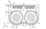
- FIG. 1 is a schematic cross-sectional view of the drive unit 100.
- the drive unit 100 is a unit for directly or indirectly controlling the driving of a vehicle (not shown) such as an electric vehicle or a hybrid vehicle using the rotating electric machine 11 .
- the direct drive control using the rotating electric machine 11 is, for example, a control mode that converts the torque generated by the rotating electric machine 11 into the driving force of the vehicle.
- Indirect drive control using the rotating electrical machine 11 is, for example, a control mode in which the rotating electrical machine 11 is used for power generation, and part or all of the power generated by this power generation is used to generate driving force for the vehicle.
- the drive unit 100 of the present embodiment is mounted on a so-called series hybrid electric vehicle. Therefore, the drive unit 100 directly and indirectly controls the drive of the vehicle.
- the drive unit 100 includes a rotating electrical machine 11 and an inverter 12 that controls the operation of the rotating electrical machine 11 inside the outer housing 10 . Further, the drive unit 100 is configured integrally with members (not shown) such as gears constituting a speed reducer and a rotation sensor in addition to the rotary electric machine 11 and the inverter 12 .
- the outer housing 10 is a housing that forms the outer shell of the drive unit 100 .
- the rotating electrical machine 11 , the inverter 12 , and the like are integrated as a drive unit 100 by being accommodated in the outer housing 10 .
- a channel (hereinafter referred to as a coolant channel) 14 is provided through which a coolant 13 for cooling heat generating elements such as the rotary electric machine 11 and the inverter 12 flows.
- the coolant 13 is a fluid such as liquid or gas used for cooling, and is, for example, cooling water, other cooling liquid, air, or the like.
- the coolant 13 cools each part housed in the outer housing 10 such as the rotating electric machine 11, the inverter 12, and other heating elements (not shown) by flowing through the coolant passage 14 and the like.
- the coolant 13 is a cooling liquid that circulates with a radiator (not shown).
- the rotating electric machine 11 is a motor generator that operates as a motor, a generator, or a motor and a generator.
- the rotating electric machine 11 can include two or more motors that operate as electric motors, generators, or motor-generators.
- the rotary electric machine 11 is composed of two motors, a first motor 20 and a second motor 25 . Therefore, the inverter 12 includes a first inverter 12 a that controls the first motor 20 and a second inverter 12 b that controls the second motor 25 .
- the first motor 20 is a drive motor (electric motor). Therefore, the vehicle in which the drive unit 100 is mounted converts the torque generated by the first motor 20 into driving force to run. Electric power for driving the first motor 20 is supplied from a battery (not shown).
- the first motor 20 has an inner housing 21 , a stator 22 and a rotor 23 .
- the inner housing 21 is a cylindrical member that fixes the stator 22 by a method such as shrink fitting.
- the inner housing 21 is cylindrical.
- the inner housing 21 includes therein a coolant channel 24 (see FIG. 2 and the like) that communicates with the coolant channel 14 of the outer housing 10 . That is, the coolant channel 24 is a channel (passage) through which the coolant 13 flows. Details of the structure of the inner housing 21 and the structure of the coolant channel 24 of the inner housing 21 (hereinafter referred to as the coolant channel 24 of the first motor 20) will be described later.
- the rotor 23 is attached to the outer housing 10 and inserted into the central portion of the stator 22 when the drive unit 100 is formed.
- the rotor 23 is rotatable with respect to the inner housing 21 and the stator 22 even after being inserted into the stator 22 .
- the stator 22 is at least one of the heat generating factors of the first motor 20 because the stator 22 is a unit through which current flows to control the first motor 20 .
- the second motor 25 is a power generation motor (generator).
- the second motor 25 is connected to an engine (internal combustion engine) (not shown) and driven by the engine.
- the power generated by the second motor 25 is accumulated in the battery that supplies power to the first motor 20 .
- the second motor 25 can consume power from the battery due to idling.
- the second motor 25 has a different application from the first motor 20, but has the same basic structure as the first motor 20.
- the second motor 25 includes an inner housing 26 , a stator 27 and a rotor 28 .
- the inner housing 26 is a cylindrical member that fixes the stator 27 by shrink fitting or the like, and has a cylindrical shape in this embodiment.
- the inner housing 26 has therein a coolant channel 29 (see FIG. 12) that communicates with the coolant channel 14 of the outer housing 10 . That is, the coolant channel 29 is a channel through which the coolant 13 flows.
- the coolant channel 29 of the inner housing 26 (hereinafter referred to as the coolant channel 29 of the second motor 25 ) has substantially the same basic structure as the coolant channel 24 of the inner housing 21 .
- the structure of the coolant channel 29 of the second motor 25 will be described later in detail together with the connecting structure of the first motor 20 and the second motor 25 .
- the rotor 28 is attached to the outer housing 10 and is rotatable even after being inserted into the stator 27 .
- the stator 27 is a unit through which current flows to control the second motor 25 , and thus is at least one of the heat generating factors of the second motor 25 .
- the inner housing 21 of the first motor 20 and the inner housing 26 of the second motor 25 are connected by a connecting pipe 30 to be integrated. Therefore, the inner housing 21 of the first motor 20 and the inner housing 26 of the second motor 25 as a whole constitute the inner housing of the rotary electric machine 11 . That is, the inner housing of rotating electric machine 11 includes a first housing and a second housing.
- the first housing is an inner housing 21 of the first motor 20 , accommodates a stator 22 as a first stator and a rotor 23 as a first rotor, and has a coolant channel 24 .
- the second housing is an inner housing 26 of the second motor 25 , accommodates a stator 27 as a second stator and a rotor 28 as a second rotor, and has a coolant channel 29 .
- the connecting pipe 30 integrates the inner housings 21 and 26 as described above, and also connects the coolant channel 24 of the first motor 20 and the coolant channel 29 of the second motor 25 .
- the coolant 13 flowing into the outer housing 10 cools the inverter 12 through the coolant flow path 14 and then flows into the coolant flow path 24 of the first motor 20 . After that, the coolant 13 flows through the coolant channel 24 of the first motor 20 and flows out to the connecting pipe 30 . Therefore, the connecting portion between the coolant channel 14 of the outer housing 10 and the first motor 20 is the inlet of the coolant 13 in the coolant channel 24 of the first motor 20 (hereinafter referred to as inlet ⁇ ).
- a connecting portion between the connecting pipe 30 and the first motor 20 is an outlet (hereinafter referred to as an outlet ⁇ ) of the coolant 13 in the coolant flow path 24 of the first motor 20 . That is, in the coolant channel 24 of the first motor 20 , the inlet ⁇ is an inlet for the coolant 13 and the outlet ⁇ is an outlet for the coolant 13 .
- the coolant 13 flows through the connecting pipe 30 into the coolant channel 29 of the second motor 25 , flows through the coolant channel 29 of the second motor 25 , and then flows out to the coolant channel 14 of the outer housing 10 . . Therefore, the connecting portion between the connecting pipe 30 and the second motor 25 is the inlet of the coolant 13 in the coolant flow path 29 of the second motor 25 (hereinafter referred to as inlet ⁇ ).
- a connecting portion between the coolant channel 14 of the outer housing 10 and the second motor 25 is an outlet (hereinafter referred to as an outlet ⁇ ) of the coolant 13 in the coolant channel 29 of the second motor 25 . That is, in the coolant channel 29 of the second motor 25 , the inlet ⁇ is an inlet for the coolant 13 and the outlet ⁇ is an outlet for the coolant 13 .
- the connecting pipe 30 linearly connects the outlet ⁇ of the inner housing 21 and the inlet ⁇ of the inner housing 26 without waste. Thereby, the connecting pipe 30 connects the coolant channel 24 of the first motor 20 and the coolant channel 29 of the second motor 25 .
- the rotation shafts of the first motor 20 and the second motor 25 are parallel.
- the direction of the rotation shafts of the first motor 20 and the second motor 25 is defined as the Z direction, and the X and Y directions are determined so as to constitute a right-handed system with respect to the Z direction.
- the coolant flow path 14 connected to the first motor 20 and the coolant flow path 14 connected to the second motor 25 are parallel in the vicinity of the connecting portion. do.
- the direction of connection of the coolant channel 14 to the first motor 20 and the second motor 25 is defined as the Y direction.
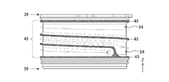
- FIG. 2 is a perspective view of the inner housing 21.
- FIG. 2 shows the inner housing 21 of the first motor 20, the inner housing 26 of the second motor 25 also has the same structure.
- the inner housing 21 of the first motor 20 has a double-tube structure consisting of an inner tube 31 and an outer tube 32. Between the inner tube 31 and the outer tube 32 is the first motor 20. are formed.
- the inner tube 31 is a generally cylindrical member and has a flange portion 33 at one end.
- a fastening portion 34 is provided on the flange portion 33 . Therefore, the flange portion 33 constitutes an attachment surface to the outer housing 10 .
- the flange portion 33 also functions as a positioning member for the outer tube 32 . That is, when the outer tube 32 is attached to the inner tube 31 by engagement, screwing, or other method, the end of the outer tube 32 hits the flange portion 33 of the inner tube 31 . Thereby, the relative positions of the inner tube 31 and the outer tube 32 in the Z direction are determined.
- the fastening portion 34 is a portion of the flange portion 33 that has screw holes for fastening the inner housing 21 to the outer housing 10 .
- the stator 22 is accommodated and fixed within the inner tube 31 .
- the peripheral surface in contact with the stator 22 is referred to as the inner peripheral surface
- the peripheral surface in contact with the outer tube 32 is referred to as the outer peripheral surface.
- the peripheral surface on the side of the outer peripheral surface of the inner tube 31 is called the inner peripheral surface
- the peripheral surface forming the outer periphery of the inner housing 21 is called the outer peripheral surface.
- the inner peripheral surface of the inner tube 31 on the positive side in the X direction is referred to as a right inner peripheral surface 36
- the inner peripheral surface on the negative side in the X direction is referred to as a left inner peripheral surface 37 . .
- the surface at the end of the inner housing 21 is called an end face.
- the end face on the Z direction positive side where the flange portion 33 of the inner tube 31 is provided is referred to as "one end face 38”
- the end face on the Z direction negative side is referred to as "the other end face 39”. It says.
- the outer tube 32 is attached to the outside of the inner tube 31 so as to cover the outer peripheral surface of the inner tube 31 . Also, when the outer tube 32 is attached to the inner tube 31 , the inner peripheral surface of the outer tube 32 contacts the outer peripheral surface of the inner tube 31 except for the portion where the refrigerant flow path 24 is formed. Therefore, the coolant channel 24 is kept watertight and airtight at least to the extent that the coolant 13 does not leak. Further, the outer tube 32 has a connecting tube 40 that connects with the coolant channel 14 of the outer housing 10 at the inlet ⁇ of the coolant 13 . The connecting pipe 40 is sometimes called a bulge.
- FIG. 3 is a perspective view of the inner tube 31.
- the inner tube 31 has a series of grooves 41 along its outer circumference. This groove portion 41 is formed so as to surround the outer peripheral surface of the inner pipe 31 .
- the adjacent groove portions 41 are separated by the wall portion 42 due to the winding or the like. Further, the wall portion 42 separates the one end surface 38 and the other end surface 39 from the groove portion 41 .
- Top portions 43 (ridge portions) of these wall portions 42 abut the inner peripheral surface of the outer tube 32 .
- FIG. 4 is a side view of the inner tube 31.
- FIG. 5 is a side view of the inner tube 31 viewed from another direction.
- the coolant flow path 24 is formed spirally around the outer peripheral surface of the inner tube 31 from the inlet ⁇ to the outlet ⁇ .
- the coolant flow path 24 is provided in substantially the entire range in which heat is generated due to the existence of the stator 22 (hereinafter referred to as a heat generation range 45) in the Z direction. Therefore, as indicated by the dashed arrow, when the coolant 13 flows through the coolant passage 24, at least the entire stator 22 is cooled.
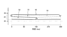
- FIG. 6 is an explanatory diagram showing the detailed configuration of the coolant channel 24.
- the position of the inlet ⁇ is used as a reference, and the position of the coolant flow path 24 along the outer peripheral surface is represented by an angle in a plane perpendicular to the Z direction (inside the XY plane).
- An angle representing a position in the coolant channel 24 is called an angular position.
- the angular positions of the inlet ⁇ and the outlet ⁇ of the coolant 13 in the coolant flow path 24 are separated, and the angular position of the inlet ⁇ is 0 degrees, whereas the outlet ⁇ is 900 degrees. Therefore, the angular positions of the entrance ⁇ and the exit ⁇ are separated by 180 degrees.
- the “separation” means the size of the inlet ⁇ and the outlet ⁇ , the range in which the coolant 13 at the positions of the inlet ⁇ and the outlet ⁇ cools the stator 22, etc. It means that the entrance ⁇ and the exit ⁇ are at substantially different angular positions.
- the structure of the coolant flow path 24, which will be described in detail below, is a structure for effectively cooling the stator 22 and the like accommodated therein even when the inlet ⁇ and the outlet ⁇ are separated. Therefore, if the cooling effect of a part or all of the stator 22 is enhanced by adopting the structure of the coolant channel 24, it can be said that the positions of the inlet ⁇ and the outlet ⁇ are substantially separated.
- the cooling performance improvement effect due to the structure of the coolant flow path 24 can be sufficiently expected, and when the separation is, for example, 45 degrees or more, cooling by the structure of the coolant flow path 24 can be expected.
- the performance improvement effect tends to be noticeable.
- the inlet ⁇ and the outlet ⁇ are separated from each other by, for example, 90 degrees or more, the effect of improving the cooling performance due to the structure of the refrigerant flow path 24 is particularly remarkable.
- the cooling effect is most likely to decrease when the inlet ⁇ and the outlet ⁇ are separated by 180 degrees. Therefore, adopting the structure of the coolant flow path 24 when the inlet ⁇ and the outlet ⁇ are separated by 180 degrees provides the most improved cooling effect.
- the coolant channel 24 includes a first channel 51 and a second channel 52 . Further, in the present embodiment, the coolant channel 24 includes a third channel 53 in addition to the first channel 51 and the second channel 52 .
- the first flow path 51 is formed along one end surface 38 of the inner housing 21 from the inlet ⁇ , and is formed so that the width along the peripheral surface increases along the direction of flow of the coolant 13. .
- the first flow path 51 is provided in a range around the peripheral surface of the inner housing 21 from the inlet ⁇ .
- the first flow path 51 is the portion of the coolant flow path 24 that is the first round from the inlet ⁇ , that is, the portion whose angular position is from 0 degrees to 360 degrees.
- the first flow path 51 is formed such that the wall portion 42 on the one end face 38 side and the top portion 43 thereof are parallel to the one end face 38 . Therefore, in a narrower sense, the first flow path 51 is formed along the one end surface 38 even if the positional relationship between the one end surface 38 and the wall portion 42 forming the first flow path 51 is considered.
- the flow direction of the coolant 13 in the coolant channel 24 is the direction along the coolant channel 24 from the inlet ⁇ to the outlet ⁇ .
- the positive direction (the direction from 0 degrees to 360 degrees) is the lower angular position with respect to the inlet ⁇ .
- “Width along the peripheral surface” refers to the length in the Z direction, that is, the distance between the wall portions 42 (especially the top portions 43) in the Z direction.
- the first flow path 51 is formed such that the width along the peripheral surface gradually increases as the angular position increases from 0 degree.
- this channel is defined as a reference channel 55 .
- a width along the peripheral surface of the reference flow path 55 is defined as a reference width.
- the first flow path 51 has a shape obtained by expanding the flow path having the reference width, that is, the reference flow path 55 in the direction of the one end surface 38 of the inner housing 21 (the positive side in the Z direction).
- the reference width which is the width of the reference flow path 55, is determined according to the pressure loss of the refrigerant 13 that allows the inlet ⁇ and the outlet ⁇ .
- the second flow path 52 is formed along the other end surface 39 of the inner housing 21, and is formed so that the width along the peripheral surface decreases toward the outlet ⁇ along the flow direction of the coolant 13. .
- the second flow path 52 is provided in a range extending around the peripheral surface of the inner housing 26 from the outlet ⁇ .
- Form along the other end surface 39 means that part or all of the last round of the coolant flow path 24 that surrounds the peripheral surface of the inner housing 21, which is closest to the other end surface 39, is included as a component. It means that in the present embodiment, the second flow path 52 is the last part of the coolant flow path 24 that reaches the outlet ⁇ , that is, the part whose angular position is from 540 degrees to 900 degrees. In particular, the second flow path 52 is formed such that the wall on the other end face 39 side and the top 43 thereof are parallel to the other end face 39 . Therefore, in a narrower sense, the second flow path 52 is formed along the other end surface 39 even when considering the positional relationship between the other end surface 39 and the wall portion 42 forming the second flow path 52 .
- the flow direction of the coolant 13 in the second flow path 52 is the direction along the outlet ⁇ from the angular position of 540 degrees. Then, as shown in FIG. 6, the second flow path 52 is formed such that the width along the peripheral surface gradually decreases as the angular position increases from the angular position of 540 degrees to the outlet ⁇ .
- the second flow path 52 has a shape obtained by expanding a reference flow path 55, which is a flow path having a reference width, toward the other end surface 39 of the inner housing 21 (in the negative direction in the Z direction).
- the third flow path 53 is provided between the first flow path 51 and the second flow path 52 and is a flow path for the coolant 13 that connects the first flow path 51 and the second flow path 52 .
- the width of the third flow path 53 along the peripheral surface is uniform. Further, the width of the third flow path 53 is formed so as to be narrower than the width of the widest portion of the first flow path 51 and narrower than the width of the widest portion of the second flow path 52 .
- the third flow path 53 is located at an angular position of 360 degrees to 540 degrees.
- the width of the third channel 53 is equal to the reference width, which is the width of the reference channel 55 .
- the structure of the third flow path 53 contributes to suppressing the pressure loss of the refrigerant 13, especially minimizing the pressure loss.
- the boundary between the first flow path 51 and the third flow path 53 and the boundary between the second flow path 52 and the third flow path 53 are formed by straight lines along the circumferential direction of the inner housing 21 .
- the boundary between the first flow path 51 and the second flow path 52 is also formed by a straight line along the circumferential direction of the inner housing 21 . This straight line corresponds to the wall portion 42 when forming the reference channel 55 . Forming the boundaries of the first flow path 51, the second flow path 52, and/or the third flow path 53 with straight lines in this way is generally based on the reference flow path 55, so that the pressure of the refrigerant 13 can be reduced. This is to reduce loss and improve cooling performance.
- FIG. 7 is an explanatory diagram showing the configuration of the coolant channel 60 of the comparative example.
- the configuration of the inner housing 21 other than the coolant flow path 60 such as the angular positions of the inlet ⁇ and the outlet ⁇ of the coolant 13, is the same as that of the inner housing 21 of the present embodiment.
- the coolant channel 60 of the comparative example is configured so as to circulate around the peripheral surface of the inner housing 21 with parallel channels 61 and inclined channels 62 .
- the parallel flow path 61 is a flow path for the coolant 13 and is parallel to the one end face 38 and the other end face 39 .
- the width along the circumferential surface of the parallel flow path 61 is uniform.
- the inclined flow path 62 is a flow path for the coolant 13 that is provided at a connection portion of the parallel flow path 61 and is formed to be inclined with respect to the parallel flow path 61 . Also, the width of the inclined channel 62 in the direction perpendicular to the direction of flow of the coolant 13 is the same as that of the parallel channel 61 .
- FIG. 8 is an explanatory diagram showing the inner surface temperature of the inner housing 21 that employs the coolant channel 60 of the comparative example.
- FIG. 8(A) represents the temperature distribution of the left inner peripheral surface 37 when the refrigerant flow path 60 of the comparative example is employed.
- FIG. 8B shows the temperature distribution of the right inner peripheral surface 36 when the coolant channel 60 of the comparative example is employed.
- FIG. 9 is an explanatory diagram showing the inner surface temperature of the inner housing 21 that employs the coolant channel 24 of this embodiment.
- FIG. 9(A) represents the temperature distribution of the left inner peripheral surface 37 when the refrigerant flow path 24 of this embodiment is employed.
- FIG. 9(B) shows the temperature distribution of the right inner peripheral surface 36 when the refrigerant flow path 24 of this embodiment is employed.
- the coolant flow path 24 can sufficiently cool the first motor 20 .
- the refrigerant flow path 24 can sufficiently cool the first motor 20 without generating the high temperature portion 66 because the refrigerant flow path 24 includes at least the first flow path 51 and the second flow path. This is because the path 52 is provided.
- the first flow path 51 has a structure in which the width gradually increases from the inlet ⁇ . Therefore, the coolant flow path 24 has a structure in which the flow path non-formed portion 65 is not generated at the end portion of the heat generation range 45 on the side of at least one end face 38 by providing the first flow path 51 .
- the second flow path 52 has a structure in which the width gradually decreases toward the outlet ⁇ . Therefore, the coolant flow path 24 has a structure in which the flow path non-formed portion 65 does not occur at least at the end of the heat generation range 45 on the other end face 39 side by including the second flow path 52 .
- the coolant channel 24 has a structure in which substantially the entire heat generation range 45 is cooled by the coolant 13 without generating the channel non-forming portion 65 by including the first channel 51 and the second channel 52 . ing.
- the refrigerant flow path 24 according to the present embodiment allows almost the entire heat generation range 45 to flow. can be cooled by a cooling medium 13 that Therefore, the coolant flow path 24 according to this embodiment can sufficiently cool the first motor 20 .
- FIG. 10 is an explanatory diagram showing the flow velocity of the coolant 13 in the coolant channel 24 according to this embodiment.
- a portion with a higher concentration black
- a portion with a lower concentration white
- the white band at an angular position of 90-odd degrees is a mere missing part of the data due to the setting of the simulation, and does not indicate that the flow velocity of the refrigerant 13 is low.
- the width along the circumferential direction of the connecting portion sharply decreases. It becomes a rapid contraction portion 71 that does.
- the connection portion between these is a rapidly expanding portion 72 in which the width along the circumferential direction is rapidly expanded. becomes.
- the velocity (flow velocity) of the fluid locally significantly decreases in these parts, resulting in a large pressure loss.
- the structure of the first flow path 51 and the second flow path 52 prevents local and significant speed reduction in the vicinity of the rapidly contracting portion 71 and the rapidly expanding portion 72 .
- pressure loss in the rapidly contracting portion 71 and the rapidly expanding portion 72 is suppressed, and sufficient cooling performance is realized including the rapidly contracting portion 71 and the rapidly expanding portion 72.
- the coolant 13 flows through the first flow path 51 from the inlet ⁇ , gradually extending over a long distance. slows down. Therefore, even in the first flow path 51 whose width is increased with respect to the reference flow path 55, the coolant 13 diffuses almost to every corner. For example, as shown in FIG. 10 , the coolant 13 easily diffuses to the corners of the sharply contracted portion 71 at the end of the first flow path 51 . As a result, the structure of the first flow path 51 sufficiently cools the portion of the heat generation range 45 on the one end face 38 side.
- the coolant 13 is slowed down by passing through the first flow path 51 and reaches the rapid contraction portion 71 in a highly diffusible state.
- the coolant 13 can flow into the third flow path 53 without large energy loss at the rapid contraction portion 71 . That is, the coolant channel 24 reduces the pressure loss in the rapidly contracting portion 71 due to the structure of the first channel 51 .
- the second flow path 52 is formed so that the width gradually decreases. , gradually increasing in speed over long distances. Therefore, even in the second flow path 52 whose width is increased with respect to the reference flow path 55, the coolant 13 is diffused almost to every corner. For example, as shown in FIG. 10, the coolant 13 easily diffuses to the corners of the rapidly expanding portion 72 at the beginning of the second flow path 52 . As a result, the structure of the second flow path 52 sufficiently cools the portion of the heat generation range 45 on the side of the other end surface 39 . In particular, since the coolant channel 24 is formed in a spiral shape, the flow direction of the coolant 13 in the rapidly expanding portion 72 is inclined toward the other end face 39 side.
- the coolant 13 flowing from the third flow path 53 flows in the direction of the wall portion 42 parallel to the other end face 39 .
- the coolant 13 is likely to diffuse even to the corner portions of the rapidly expanding portion 72 .
- the refrigerant 13 is easily diffused in the rapidly expanding portion 72 as well, thereby suppressing local speed reduction and pressure loss in or near the rapidly expanding portion 72 .
- the refrigerant flow path 24 has a structure in which the pressure loss of the refrigerant 13 is suppressed by the first flow path 51 and the second flow path 52. It is notable to the extent that it provides better pressure drop control than flow path 60 . That is, when the pressure loss of the refrigerant 13 is compared, the pressure loss of the refrigerant 13 at the outlet ⁇ of the refrigerant flow path 24 according to the present embodiment is smaller than the pressure loss of the refrigerant 13 at the outlet ⁇ of the refrigerant flow path 60 of the comparative example. .
- FIG. 11 is a graph schematically showing changes in the flow velocity and temperature of the coolant 13.
- FIG. 11 in the coolant channel 24 , the velocity of the coolant 13 is low and the temperature is high in the vicinity of the rapidly expanding portion 72 .
- the rapidly expanding portion 72 and the vicinity thereof are the most severe environment with respect to the cooling performance of the first motor 20, and tend to reach high temperatures.
- FIG. 9 even the portion corresponding to the rapidly expanding portion 72 does not reach a significantly high temperature, and the entire right inner peripheral surface 36 and left inner peripheral surface 37 in contact with the stator 22 are the refrigerant flow paths. 24 is fully cooled.
- FIG. 12 is an explanatory diagram showing the configuration of the coolant flow path of the entire rotary electric machine 11.
- the coolant flow path 24 of the first motor 20 extends from the inlet ⁇ in the positive Z direction in a so-called right-handed (right-handed) spiral to reach the outlet ⁇ .
- the coolant flow path 29 of the second motor 25 extends from the inlet ⁇ in the negative direction in the Z direction in a so-called left-handed (left-handed) spiral to reach the outlet ⁇ .
- the coolant flow path 24 of the first motor 20 and the coolant flow path 29 of the second motor 25 have different helicities (or chiralities), and are oppositely wound spirals.
- the coolant of the first motor 20 can be supplied without needlessly long connecting pipes.
- the flow path 24 and the coolant flow path 29 of the second motor 25 can be connected linearly and at the shortest distance by the connecting pipe 30 . Therefore, the first motor 20 and the second motor 25 are arranged in a space-saving manner, and a compact rotating electric machine 11 is provided.
- each mounting surface of the first motor 20 and the second motor 25 to the outer housing 10 can be easily fixed. This makes it easier to arrange the first motor 20 and the second motor 25 in a space-saving manner than when the respective mounting surfaces are uneven.
- the coolant channel 29 of the second motor 25 is formed in a reverse-wound spiral with respect to the coolant channel 24 of the first motor 20. 24.
- the inner housing 26 of the second motor 25 is formed of an inner tube 81 and an outer tube 82 like the inner housing 21 of the first motor 20 .
- a coolant channel 29 of the second motor 25 is formed on the outer peripheral surface of the inner tube 81 .
- the end face on the Z-direction positive side where the flange portion is provided is one end face 83
- the end face on the Z-direction negative side is the other end face 84 .
- the coolant channel 29 of the second motor 25 includes a first channel 91 and a second channel 92 .
- the coolant channel 29 of the second motor 25 further includes a third channel 93 .
- the first flow path 91 is formed along one end surface 83 of the inner housing 26 and is formed so that the width along the peripheral surface increases along the direction of flow of the coolant 13 .
- the second flow path 92 is formed along the other end face 84 of the inner housing 26 from the inlet ⁇ , and is formed such that the width along the peripheral surface decreases from the inlet ⁇ to the outlet ⁇ along the flow direction of the coolant 13. be done.
- the third flow path 93 is formed between the first flow path 91 and the second flow path 92 so as to have a uniform width along the peripheral surface, and connects the first flow path 91 and the second flow path 92. . That is, the coolant channel 29 of the second motor 25 is formed in the same manner as the coolant channel 24 of the first motor 20 except that it is reversely wound.
- the coolant flow path 14 of the outer housing 10 is preferably formed, for example, as shown in FIG.
- the coolant flow path 14 of the outer housing 10 connects the respective parts constituting the drive unit 100 by substantially the shortest route.
- the coolant flow path 14 of the outer housing 10 is formed in this way, the inlet and outlet of the coolant to each motor constituting the rotating electric machine are separated from each other.
- the inlet and outlet of the coolant flow path in each motor constituting the rotating electric machine are spaced apart by approximately 180 degrees. This is as indicated by the inlet ⁇ and the outlet ⁇ of the coolant channel 24 of the first motor 20 and the inlet ⁇ and the outlet ⁇ of the coolant channel 29 of the second motor 25 in FIG.
- the inlet ⁇ and the outlet ⁇ of the coolant flow path 24 of the first motor 20 should not be spaced apart so as not to substantially generate the flow path non-forming portion 65. is desirable.
- the second motor 25 is also the same. That is, considering only the cooling performance for each motor that constitutes the rotating electrical machine, it is desirable that the inlet and outlet of the coolant flow path are not substantially separated from each other. However, when considering the cooling performance of the first motor 20 and/or the second motor 25 alone in this way, the refrigerant flow path 14 of the outer housing 10 becomes redundant, resulting in the disadvantage that the drive unit 100 cannot be configured compactly.
- the structure of the coolant channel 24 and the coolant channel 29 of the present embodiment and the connecting structure thereof enable the drive unit 100 to be formed as compact as possible with respect to the channel of the coolant 13. , which is the best structure for maximizing the cooling performance of the first motor 20 and the second motor 25 .
- the coolant flow path 24 of the first motor 20 includes the first flow path 51 and the second flow path 52 as well as the third flow path 53 connecting them.
- the refrigerant channel 29 of the second motor 25 is similar to this, and in addition to the first channel 91 and the second channel 92, it has a third channel 93 connecting them.
- the third flow paths 53 and 93 may be omitted in consideration of cooling performance, pressure loss, and the like. Also in this case, the same effect as the refrigerant flow path 24 or the like according to the above-described embodiment can be obtained.
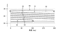
- FIG. 13 is an explanatory diagram showing the configuration of the coolant channel 95 of the first modified example.
- the coolant channel 95 of the modified example is a coolant channel in which the third channel 53 in the coolant channel 24 of the first motor 20 is omitted and the first channel 51 and the second channel 52 are directly connected.
- a range of angular positions from 0 degrees (inlet ⁇ ) to 360 degrees or 180 degrees is formed along one end face 38 and along the flow direction of the coolant 13 . This is the range formed so that the width along the . Therefore, in the coolant channel 85 of the modified example, the first channel 51 is in the range from 0 degrees to 360 degrees or 180 degrees.
- the coolant channel 85 of the modified example a range of angular positions from 180 degrees or 360 degrees to 540 degrees (outlet ⁇ ) is formed along the other end face 39 and along the flow direction of the coolant 13. It is a range formed so that the width along the peripheral surface decreases toward the outlet ⁇ . Therefore, in the refrigerant channel 85, the second channel 52 is in the range from 180 degrees or 360 degrees to 540 degrees (outlet ⁇ ).
- the range of angular positions from 180 degrees to 360 degrees satisfies the conditions for the first flow path 51 by being integrated with the first flow path 51 as described above, and is integrated with the second flow path 52.
- the conditions for the second flow path 52 are satisfied by.
- the range of angular positions from 180 degrees to 360 degrees can belong to either the first channel 51 or the second channel 52 .
- the width along the circumferential direction is wider than that of the reference flow path 55, it is different from the third flow paths 53 and 93. FIG. Therefore, the range of angular positions from 180 degrees to 360 degrees belongs to either one or both of the first channel 51 and the second channel 52 .
- the coolant channel 24 of the first motor 20 has the third channel 53 and the coolant channel 29 of the second motor 25 has the third channel 93 .
- These third flow paths 53 and 93 are provided over the half circumferences of the inner housings 21 and 26 .
- the number of turns of the third flow passages 53 and 93 can be arbitrarily changed by adaptation according to the permissible pressure loss (hereinafter referred to as permissible pressure loss) and the dimensions of the inlets ⁇ and ⁇ and the outlets ⁇ and ⁇ . can do.
- FIG. 14 is an explanatory diagram showing the configuration of the coolant channel 96 according to the second modified example.
- the permissible pressure loss is large and a relatively large pressure loss is permissible
- the number of turns of the third flow paths 53, 93 can be increased.
- the allowable pressure loss is small and only a relatively small pressure loss can be allowed
- the number of turns of the third flow paths 53, 93 can be reduced (see FIG. 13).
- changing the number of turns of the third flow paths 53 and 93 is synonymous with changing the number of turns of the refrigerant flow paths 24 and 29 .
- the number of turns of the third flow paths 53, 93 correlates with the width of the third flow paths 53, 93 and the spiral angle (pitch) formed by the third flow paths 53, 93 and the refrigerant flow paths 24, 29. , and by determining one of these, the other parameters are automatically determined. Therefore, instead of changing the number of turns of the third flow paths 53 and 93 as in the second modification, the width of the third flow paths 53 and 93, or the third flow paths 53 and 93 and the coolant flow path 24 , 29 may be varied. Also, the allowable pressure loss is determined by adaptation according to the dimensions of the stators 22 and 27, for example.
- the rotary electric machine 11 includes the inner housing 21 (26) that is a cylindrical housing.
- the inner housing 21 (26) which is a cylindrical housing, includes a coolant channel 24 (29) through which the coolant 13 flows and an inlet ⁇ ( ⁇ ) through which the coolant 13 flows into the coolant channel 24 (29). and an outlet ⁇ ( ⁇ ) through which the coolant 13 flows out from the coolant channel 24 (29).
- the coolant channel 24 is formed so as to spirally surround the peripheral surface of the inner housing 21 (26).
- the coolant flow path 24 (29) is formed along one end surface 38 (83) of the inner housing 21 (26), along the flow direction of the coolant 13 from the inlet ⁇ ( ⁇ ), A first flow path 51 (91) formed to increase in width along the peripheral surface and a first flow path 51 (91) formed along the other end surface 39 (84) of the inner housing 21 (26) and through which the coolant 13 flows.
- a second flow path 52 (92) formed so that the width along the peripheral surface decreases toward the outlet ⁇ ( ⁇ ) along the direction.
- the coolant flow path 24 (29) becomes the first flow path 51 (91) and the second flow path 52 ( 92), even when the inlet ⁇ ( ⁇ ) and the outlet ⁇ ( ⁇ ) of the coolant 13 are spaced apart, substantially no channel non-forming portion 65 is generated.
- the first flow path 51 (91) and the second flow path 52 (92) suppress a local decrease in speed and an increase in pressure loss of the refrigerant 13, and have a structure in which sufficient cooling performance can be obtained almost entirely. It has become.
- substantially the entire heat generation range 45 flows through the refrigerant flow path 24 (29) by the first flow path 51 (91) and the second flow path 52 (92). It can be cooled by coolant 13 . Therefore, in the rotary electric machine 11 in which the coolant flow path 24 (29) having the first flow path 51 (91) and the second flow path 52 (92) is formed, the cooling performance is improved, and the necessary cooling performance can be obtained. .
- the inlet ⁇ ( ⁇ ) and the outlet ⁇ ( ⁇ ) of the coolant 13 are provided at positions spaced apart in the circumferential direction of the inner housing 21 (26). Therefore, the effect of improving the cooling property is particularly remarkable.
- the coolant flow path 24 (29) is positioned between the first flow path 51 (91) and the second flow path 52 (92) as a third flow path having a uniform width.
- a path 53 (93) is provided.
- the uniform width of the third flow path 53 (93) reduces the speed reduction and pressure loss of the coolant 13 flowing through the coolant flow path 24 (29). Therefore, by including the third flow path 53 (93) in the refrigerant flow path 24 (29), it becomes easier to obtain a necessary and sufficient cooling effect while satisfying the allowable pressure loss condition.
- the width of the third flow path 53 (93) is narrower than the width of the widest portion of the first flow path 51 (91), and the width of the second flow path 52 Narrower than the width at the widest part of (92).
- the reference flow path 55 is a flow path that connects the inlet ⁇ ( ⁇ ) and the outlet ⁇ ( ⁇ ) with a uniform width determined according to the permissible pressure loss of the coolant 13.
- the first flow path 51 (91) has a shape obtained by expanding the reference flow path 55 toward one end surface 38 (83) of the inner housing 21 (26).
- the second flow path 52 (92) has a shape extending the reference flow path 55 toward the other end surface 39 (84) of the inner housing 21 (26).
- the first flow path 51 (91) and the second flow path 52 (92) move the reference flow path 55 toward the one end surface 38 (83) and the other end surface 38 (84). It has a shape expanded to each. Therefore, in the coolant flow path 24 (29), the flow path non-formation portion 65 generated when forming the reference flow path 55 is the first flow path 51 (91) and the second flow path 52 (92). ). As a result, the rotating electric machine 11 is cooled more reliably.
- the boundary between the first flow path 51 (91) and the third flow path 53 (93), the second flow path 52 (92) and the third flow path 53 ( 93) is formed by a straight line along the circumferential direction of the inner housing 21 (26).
- the third flow path 53 (93) becomes a flow path conforming to the reference flow path 55 in general.
- the pressure loss of the coolant 13 in the third flow path 53 (93) is reduced, and the cooling performance is further enhanced.
- the first flow path 51 (91) is provided in a range from the inlet ⁇ ( ⁇ ) to the circumference of the inner housing 21 (26).
- the second flow path 52 (92) is provided in a range extending from the outlet ⁇ ( ⁇ ) around the peripheral surface of the inner housing 21 (26).
- the range of one round from the inlet ⁇ ( ⁇ ) and the range of one round from the outlet ⁇ ( ⁇ ) are particularly prone to the occurrence of flow path non-formed portions 65 . Therefore, the first flow path 51 (91) is provided in the range of at least one turn from the inlet ⁇ ( ⁇ ), and the second flow path 52 (92) is provided in the range of at least one turn from the outlet ⁇ ( ⁇ ). , the cooling performance of the rotary electric machine 11 is likely to be improved.
- the first flow path 51 (91) may be provided beyond the range of one round from the inlet ⁇ ( ⁇ ), and the second flow path 52 (92) may be provided in the range of one round from the outlet ⁇ ( ⁇ ). may be provided.
- the third flow path 53 (93) is not provided as shown in FIG. 13, the first flow path 51 (91) and/or the second flow path 52 (92) , may not be provided in the entire range of one round.
- the inner housing 21 has the inner housing 21 as the first housing, the inner housing 26 as the second housing, and the connecting pipe 30.
- An inner housing 21 that is a first housing accommodates a stator 22 that is a first stator and a rotor 23 that is a first rotor, and has coolant flow paths 24 .
- the inner housing 26 that is the second housing accommodates the stator 27 that is the second stator and the rotor 28 that is the second rotor, and has coolant flow paths 29 .
- the connecting pipe 30 linearly connects the outlet ⁇ of the inner housing 21, which is the first housing, and the inlet ⁇ of the inner housing 26, which is the second housing, without waste. Therefore, the rotary electric machine 11 containing two motors can be compactly configured while maintaining the cooling performance thereof. Secondarily, the cost of the rotary electric machine 11 is reduced.
- the coolant channel 29 of the inner housing 26 that is the second housing is formed in a reverse spiral shape with respect to the coolant channel 24 of the inner housing 21 that is the first housing. It is In this way, when the two connected coolant flow paths 24 and 29 are formed in a reverse spiral shape, the rotating electric machine 11 containing two motors can be particularly compactly configured while maintaining cooling performance thereof.
- the first motor 20 may be a motor for power generation
- the second motor 25 may be a motor for driving
- both the first motor 20 and the second motor 25 may be drive motors
- both the first motor 20 and the second motor 25 may be power generation motors
- the rotary electric machine 11 may be configured to include only one of the first motor 20 and the second motor 25 .
- the coolant channel 24 is formed by the groove 41 provided on the outer peripheral surface of the inner tube 31, but instead, by providing a similar groove on the inner peripheral surface of the outer tube 32, the coolant A channel 24 can be formed.
- the coolant channel 24 may be formed by providing grooves on both the outer peripheral surface of the inner tube 31 and the inner peripheral surface of the outer tube 32 . The same applies to the coolant channel 29 as well.
- the width of the first flow path 51 smoothly increases, and the width of the second flow path 52 smoothly decreases.
- the widths of the first channel 51 and the second channel 52 may change stepwise, for example. Even when the widths of the first flow path 51 and the second flow path 52 change stepwise, the same effect as in the above-described embodiment and the like can be obtained. However, it is preferable that the widths of the first flow path 51 and the second flow path 52 change as smoothly as possible as in the above embodiment. The same applies to the coolant channel 29 as well.
Landscapes
- Engineering & Computer Science (AREA)
- Power Engineering (AREA)
- Motor Or Generator Cooling System (AREA)
- Motor Or Generator Frames (AREA)
Abstract
Description
図2は、インナーハウジング21の斜視図である。図2では、第1モータ20のインナーハウジング21を示しているが、第2モータ25のインナーハウジング26もこれと同様の構造を有する。図2に示すように、第1モータ20のインナーハウジング21は、内管31と外管32とからなる二重管構造となっており、内管31と外管32の間に第1モータ20の冷媒流路24が形成される。
以下、上記のように構成される冷媒流路24の作用を、比較例の冷媒流路60と対比しながら説明する。
図12は、回転電機11全体の冷媒流路の構成を示す説明図である。図12に示すように、第1モータ20の冷媒流路24は、入口αからZ方向正方向に、いわゆる右巻き(右手巻き)の螺旋で延伸されて出口βに至る。これに対し、第2モータ25の冷媒流路29は、入口γからZ方向負方向に、いわゆる左巻き(左手巻き)の螺旋で延伸されて出口δに至る。すなわち、第1モータ20の冷媒流路24と第2モータ25の冷媒流路29は、ヘリシティ(あるいはカイラリティ)が異なり、互いに逆巻きの螺旋となっている。このように、第1モータ20の冷媒流路24と第2モータ25の冷媒流路29を互いに逆巻きの螺旋状に形成すると、無駄に長い接続管を設けなくても、第1モータ20の冷媒流路24と第2モータ25の冷媒流路29は、連結管30によって直線的に最短で接続され得る。このため、第1モータ20と第2モータ25は省スペースに配置され、コンパクトな回転電機11が提供される。また、第1モータ20の冷媒流路24と第2モータ25の冷媒流路29を互いに逆巻きの螺旋状に形成すると、アウターハウジング10に対する第1モータ20と第2モータ25の各取り付け面を容易に揃えることができ、各取り付け面が不揃いである場合よりも、第1モータ20と第2モータ25を省スペースに配置しやすい。
上記実施形態においては、第1モータ20の冷媒流路24は、第1流路51と第2流路52に加えて、これらを連結する第3流路53を備える。また、第2モータ25の冷媒流路29もこれと同様であり、第1流路91と第2流路92に加えて、これらを連結する第3流路93を備える。しかし、冷却性や圧力損失等を考慮して、第3流路53,93が省略される場合がある。この場合も、上記実施形態に係る冷媒流路24等と同様の効果が得られる。
上記実施形態においては、第1モータ20の冷媒流路24は第3流路53を備え、第2モータ25の冷媒流路29は第3流路93を備える。そして、これらの第3流路53,93は、インナーハウジング21,26の半周にわたって設けられている。しかし、第3流路53,93の巻数は、許容される圧力損失(以下、許容圧力損失という)や入口α,γ、出口β,δの各寸法等に応じて、適合により、任意に変更することができる。
Claims (9)
- 冷媒が流通する流路と、前記冷媒が前記流路に流入する入口と、前記冷媒が前記流路から流出する出口と、を有する筒状のハウジングを備え、前記流路が、前記ハウジングの周面を螺旋状に周回するように形成された回転電機であって、
前記流路が、
前記ハウジングの一方の端面に沿って形成され、かつ、前記入口から前記冷媒の流通方向に沿って、前記周面に沿った幅が拡大するように形成された第1流路と、
前記ハウジングの他方の端面に沿って形成され、かつ、前記冷媒の流通方向に沿って前記出口にかけて、前記周面に沿った幅が縮小するように形成された第2流路と、
を備える、
回転電機。 - 請求項1に記載の回転電機であって、
前記入口と前記出口が、前記ハウジングの周方向において離間した位置に設けられている、
回転電機。 - 請求項1または2に記載の回転電機であって、
前記流路が、前記第1流路と前記第2流路の間に、幅が均一な第3流路を備える、
回転電機。 - 請求項3に記載の回転電機であって、
前記第3流路の幅は、前記第1流路の最も広い部分における幅よりも狭く、かつ、前記第2流路の最も広い部分における幅よりも狭い、
回転電機。 - 請求項1~4のいずれか1項に記載の回転電機であって、
前記入口と前記出口を、許容する前記冷媒の圧力損失に応じて定まる均一な幅で連結する流路を基準流路とするときに、
前記第1流路は、前記基準流路を、前記ハウジングの前記一方の端面の方向に拡張した形状を有し、
前記第2流路は、前記基準流路を、前記ハウジングの前記他方の端面の方向に拡張した形状を有する、
回転電機。 - 請求項3または4に記載の回転電機であって、
前記第1流路と前記第3流路の境界、及び、前記第2流路と前記第3流路の境界は、前記ハウジングの周方向に沿った直線で形成されている、
回転電機。 - 請求項1~6のいずれか1項に記載の回転電機であって、
前記第1流路は、前記入口から、前記ハウジングの周面を一周する範囲に設けられ、
前記第2流路は、前記出口から、前記ハウジングの周面を一周する範囲に設けられている、
回転電機。 - 請求項1~7のいずれか1項に記載の回転電機であって、
前記ハウジングは、
第1固定子及び第1回転子を収容し、かつ、前記流路を有する第1ハウジングと、
第2固定子及び第2回転子を収容し、かつ、前記流路を有する第2ハウジングと、
前記第1ハウジングの前記出口と前記第2ハウジングの前記入口とを直線的に連結する連結管と、
を有する、
回転電機。 - 請求項8に記載の回転電機であって、
前記第2ハウジングの前記流路は、前記第1ハウジングの前記流路に対して逆巻きの螺旋状に形成されている、
回転電機。
Priority Applications (7)
| Application Number | Priority Date | Filing Date | Title |
|---|---|---|---|
| EP21929432.9A EP4307535A4 (en) | 2021-03-08 | 2021-03-08 | ROTATING ELECTRIC MACHINE |
| CN202180095311.9A CN116941165A (zh) | 2021-03-08 | 2021-03-08 | 旋转电机 |
| US18/280,601 US20240039361A1 (en) | 2021-03-08 | 2021-03-08 | Rotating electrical machine |
| PCT/JP2021/009083 WO2022190183A1 (ja) | 2021-03-08 | 2021-03-08 | 回転電機 |
| JP2023504900A JPWO2022190183A1 (ja) | 2021-03-08 | 2021-03-08 | |
| BR112023017847A BR112023017847A2 (pt) | 2021-03-08 | 2021-03-08 | Máquina elétrica rotativa |
| MX2023010336A MX2023010336A (es) | 2021-03-08 | 2021-03-08 | Maquina electrica rotativa. |
Applications Claiming Priority (1)
| Application Number | Priority Date | Filing Date | Title |
|---|---|---|---|
| PCT/JP2021/009083 WO2022190183A1 (ja) | 2021-03-08 | 2021-03-08 | 回転電機 |
Publications (1)
| Publication Number | Publication Date |
|---|---|
| WO2022190183A1 true WO2022190183A1 (ja) | 2022-09-15 |
Family
ID=83227509
Family Applications (1)
| Application Number | Title | Priority Date | Filing Date |
|---|---|---|---|
| PCT/JP2021/009083 WO2022190183A1 (ja) | 2021-03-08 | 2021-03-08 | 回転電機 |
Country Status (7)
| Country | Link |
|---|---|
| US (1) | US20240039361A1 (ja) |
| EP (1) | EP4307535A4 (ja) |
| JP (1) | JPWO2022190183A1 (ja) |
| CN (1) | CN116941165A (ja) |
| BR (1) | BR112023017847A2 (ja) |
| MX (1) | MX2023010336A (ja) |
| WO (1) | WO2022190183A1 (ja) |
Citations (4)
| Publication number | Priority date | Publication date | Assignee | Title |
|---|---|---|---|---|
| JP2014505821A (ja) * | 2010-12-14 | 2014-03-06 | アルフレット ケルヒャー ゲゼルシャフト ミット ベシュレンクテル ハフツング ウント コンパニー コマンディトゲゼルシャフト | 高圧洗浄機のためのモータポンプユニット及び高圧洗浄機 |
| WO2015098328A1 (ja) | 2013-12-27 | 2015-07-02 | 日立オートモティブシステムズ株式会社 | 回転電機 |
| WO2019022116A1 (ja) * | 2017-07-28 | 2019-01-31 | 日本電産トーソク株式会社 | モータ |
| WO2019022123A1 (ja) * | 2017-07-28 | 2019-01-31 | 日本電産トーソク株式会社 | モータ |
Family Cites Families (9)
| Publication number | Priority date | Publication date | Assignee | Title |
|---|---|---|---|---|
| US9331551B2 (en) * | 2011-02-18 | 2016-05-03 | Honda Motor Co., Ltd. | Case of electric rotating machine |
| JP2014087248A (ja) * | 2012-10-26 | 2014-05-12 | Toshiba Corp | 液冷式の回転電機および回転電機システム |
| JP5978954B2 (ja) * | 2012-11-26 | 2016-08-24 | 三菱自動車工業株式会社 | 回転電機装置 |
| DE102014102632A1 (de) * | 2013-03-04 | 2014-09-04 | Remy Technologies Llc | Flüssigkeitsgekühlte rotierende elektrische Maschine mit Kühlmantel mit bidirektionalem Strom |
| DE102016217361A1 (de) * | 2016-09-12 | 2018-03-15 | Volkswagen Aktiengesellschaft | Rotatorische Elektromaschine |
| FR3070558B1 (fr) * | 2017-08-24 | 2020-06-12 | IFP Energies Nouvelles | Machine electrique avec dispositif de refroidissement comprenant un canal partiellement subdivise |
| JP6852810B2 (ja) * | 2017-11-17 | 2021-03-31 | アイシン・エィ・ダブリュ株式会社 | 車両用駆動装置 |
| CN110957842B (zh) * | 2018-09-27 | 2023-10-20 | 株式会社电装 | 旋转电机 |
| JP6749438B2 (ja) * | 2019-02-20 | 2020-09-02 | 三菱電機株式会社 | 回転電機 |
-
2021
- 2021-03-08 BR BR112023017847A patent/BR112023017847A2/pt unknown
- 2021-03-08 MX MX2023010336A patent/MX2023010336A/es unknown
- 2021-03-08 EP EP21929432.9A patent/EP4307535A4/en active Pending
- 2021-03-08 WO PCT/JP2021/009083 patent/WO2022190183A1/ja active Application Filing
- 2021-03-08 US US18/280,601 patent/US20240039361A1/en active Pending
- 2021-03-08 CN CN202180095311.9A patent/CN116941165A/zh active Pending
- 2021-03-08 JP JP2023504900A patent/JPWO2022190183A1/ja active Pending
Patent Citations (4)
| Publication number | Priority date | Publication date | Assignee | Title |
|---|---|---|---|---|
| JP2014505821A (ja) * | 2010-12-14 | 2014-03-06 | アルフレット ケルヒャー ゲゼルシャフト ミット ベシュレンクテル ハフツング ウント コンパニー コマンディトゲゼルシャフト | 高圧洗浄機のためのモータポンプユニット及び高圧洗浄機 |
| WO2015098328A1 (ja) | 2013-12-27 | 2015-07-02 | 日立オートモティブシステムズ株式会社 | 回転電機 |
| WO2019022116A1 (ja) * | 2017-07-28 | 2019-01-31 | 日本電産トーソク株式会社 | モータ |
| WO2019022123A1 (ja) * | 2017-07-28 | 2019-01-31 | 日本電産トーソク株式会社 | モータ |
Also Published As
| Publication number | Publication date |
|---|---|
| JPWO2022190183A1 (ja) | 2022-09-15 |
| BR112023017847A2 (pt) | 2023-10-10 |
| MX2023010336A (es) | 2023-09-13 |
| US20240039361A1 (en) | 2024-02-01 |
| EP4307535A4 (en) | 2024-05-29 |
| EP4307535A1 (en) | 2024-01-17 |
| CN116941165A (zh) | 2023-10-24 |
Similar Documents
| Publication | Publication Date | Title |
|---|---|---|
| US6909210B1 (en) | Cooling system for dynamoelectric machine | |
| JP6314158B2 (ja) | 回転電機 | |
| JP3289698B2 (ja) | 回転電機 | |
| JP2000102216A (ja) | 液冷式非同期電気機械 | |
| WO2009122597A1 (ja) | 駆動装置 | |
| JP5146363B2 (ja) | 電動機 | |
| US11577600B2 (en) | Motor, motor cooling system, and electric vehicle | |
| JP4935839B2 (ja) | モータのハウジング構造 | |
| JP2007325436A (ja) | 全閉形液冷電動機 | |
| US11283331B2 (en) | Rotating electric machine | |
| JP2009195082A (ja) | ステータの冷却構造 | |
| WO2022190183A1 (ja) | 回転電機 | |
| US20230336048A1 (en) | Cooling jacket and motor | |
| JP2020058219A (ja) | 回転電機 | |
| AU2014322794B2 (en) | An electric or hybrid vehicle using motor-generator having shaft with centrifugal fan blades for cooling | |
| JP2010206994A (ja) | 電動機 | |
| JP4501667B2 (ja) | 車両駆動装置 | |
| JP7484547B2 (ja) | 車両用駆動装置 | |
| JP5626085B2 (ja) | ハイブリッド建設機械 | |
| CN112436654A (zh) | 具有冷却功能的电机壳体和电机 | |
| WO2020202705A1 (ja) | 制御弁 | |
| JP5565745B2 (ja) | モータハウジング構造 | |
| JP7241096B2 (ja) | モータ、及びインバータ一体型回転電機 | |
| CN220732450U (zh) | 电机及车辆用动力系统 | |
| JP2008144742A (ja) | スクリュー形過給機の冷却構造 |
Legal Events
| Date | Code | Title | Description |
|---|---|---|---|
| 121 | Ep: the epo has been informed by wipo that ep was designated in this application |
Ref document number: 21929432 Country of ref document: EP Kind code of ref document: A1 |
|
| WWE | Wipo information: entry into national phase |
Ref document number: 2301005486 Country of ref document: TH Ref document number: MX/A/2023/010336 Country of ref document: MX |
|
| WWE | Wipo information: entry into national phase |
Ref document number: 2023504900 Country of ref document: JP |
|
| WWE | Wipo information: entry into national phase |
Ref document number: 202180095311.9 Country of ref document: CN Ref document number: 18280601 Country of ref document: US |
|
| REG | Reference to national code |
Ref country code: BR Ref legal event code: B01A Ref document number: 112023017847 Country of ref document: BR |
|
| WWE | Wipo information: entry into national phase |
Ref document number: 2021929432 Country of ref document: EP |
|
| ENP | Entry into the national phase |
Ref document number: 112023017847 Country of ref document: BR Kind code of ref document: A2 Effective date: 20230901 |
|
| NENP | Non-entry into the national phase |
Ref country code: DE |
|
| ENP | Entry into the national phase |
Ref document number: 2021929432 Country of ref document: EP Effective date: 20231009 |