WO2022186110A1 - 機械学習システム、認識器、学習方法、及びプログラム - Google Patents
機械学習システム、認識器、学習方法、及びプログラム Download PDFInfo
- Publication number
- WO2022186110A1 WO2022186110A1 PCT/JP2022/008167 JP2022008167W WO2022186110A1 WO 2022186110 A1 WO2022186110 A1 WO 2022186110A1 JP 2022008167 W JP2022008167 W JP 2022008167W WO 2022186110 A1 WO2022186110 A1 WO 2022186110A1
- Authority
- WO
- WIPO (PCT)
- Prior art keywords
- image
- graphic
- learning
- synthesized
- machine learning
- Prior art date
- Legal status (The legal status is an assumption and is not a legal conclusion. Google has not performed a legal analysis and makes no representation as to the accuracy of the status listed.)
- Ceased
Links
Images




Classifications
-
- G—PHYSICS
- G06—COMPUTING OR CALCULATING; COUNTING
- G06V—IMAGE OR VIDEO RECOGNITION OR UNDERSTANDING
- G06V10/00—Arrangements for image or video recognition or understanding
- G06V10/70—Arrangements for image or video recognition or understanding using pattern recognition or machine learning
- G06V10/77—Processing image or video features in feature spaces; using data integration or data reduction, e.g. principal component analysis [PCA] or independent component analysis [ICA] or self-organising maps [SOM]; Blind source separation
- G06V10/774—Generating sets of training patterns; Bootstrap methods, e.g. bagging or boosting
-
- A—HUMAN NECESSITIES
- A61—MEDICAL OR VETERINARY SCIENCE; HYGIENE
- A61B—DIAGNOSIS; SURGERY; IDENTIFICATION
- A61B8/00—Diagnosis using ultrasonic, sonic or infrasonic waves
- A61B8/13—Tomography
- A61B8/14—Echo-tomography
-
- G—PHYSICS
- G06—COMPUTING OR CALCULATING; COUNTING
- G06N—COMPUTING ARRANGEMENTS BASED ON SPECIFIC COMPUTATIONAL MODELS
- G06N3/00—Computing arrangements based on biological models
- G06N3/02—Neural networks
- G06N3/04—Architecture, e.g. interconnection topology
- G06N3/0464—Convolutional networks [CNN, ConvNet]
-
- G—PHYSICS
- G06—COMPUTING OR CALCULATING; COUNTING
- G06N—COMPUTING ARRANGEMENTS BASED ON SPECIFIC COMPUTATIONAL MODELS
- G06N3/00—Computing arrangements based on biological models
- G06N3/02—Neural networks
- G06N3/08—Learning methods
- G06N3/084—Backpropagation, e.g. using gradient descent
-
- G—PHYSICS
- G06—COMPUTING OR CALCULATING; COUNTING
- G06N—COMPUTING ARRANGEMENTS BASED ON SPECIFIC COMPUTATIONAL MODELS
- G06N3/00—Computing arrangements based on biological models
- G06N3/02—Neural networks
- G06N3/08—Learning methods
- G06N3/09—Supervised learning
-
- G—PHYSICS
- G06—COMPUTING OR CALCULATING; COUNTING
- G06T—IMAGE DATA PROCESSING OR GENERATION, IN GENERAL
- G06T1/00—General purpose image data processing
-
- G—PHYSICS
- G06—COMPUTING OR CALCULATING; COUNTING
- G06T—IMAGE DATA PROCESSING OR GENERATION, IN GENERAL
- G06T5/00—Image enhancement or restoration
- G06T5/50—Image enhancement or restoration using two or more images, e.g. averaging or subtraction
-
- G—PHYSICS
- G06—COMPUTING OR CALCULATING; COUNTING
- G06T—IMAGE DATA PROCESSING OR GENERATION, IN GENERAL
- G06T7/00—Image analysis
- G06T7/0002—Inspection of images, e.g. flaw detection
- G06T7/0012—Biomedical image inspection
-
- G—PHYSICS
- G06—COMPUTING OR CALCULATING; COUNTING
- G06V—IMAGE OR VIDEO RECOGNITION OR UNDERSTANDING
- G06V10/00—Arrangements for image or video recognition or understanding
- G06V10/94—Hardware or software architectures specially adapted for image or video understanding
- G06V10/945—User interactive design; Environments; Toolboxes
-
- G—PHYSICS
- G16—INFORMATION AND COMMUNICATION TECHNOLOGY [ICT] SPECIALLY ADAPTED FOR SPECIFIC APPLICATION FIELDS
- G16H—HEALTHCARE INFORMATICS, i.e. INFORMATION AND COMMUNICATION TECHNOLOGY [ICT] SPECIALLY ADAPTED FOR THE HANDLING OR PROCESSING OF MEDICAL OR HEALTHCARE DATA
- G16H30/00—ICT specially adapted for the handling or processing of medical images
- G16H30/40—ICT specially adapted for the handling or processing of medical images for processing medical images, e.g. editing
-
- G—PHYSICS
- G16—INFORMATION AND COMMUNICATION TECHNOLOGY [ICT] SPECIALLY ADAPTED FOR SPECIFIC APPLICATION FIELDS
- G16H—HEALTHCARE INFORMATICS, i.e. INFORMATION AND COMMUNICATION TECHNOLOGY [ICT] SPECIALLY ADAPTED FOR THE HANDLING OR PROCESSING OF MEDICAL OR HEALTHCARE DATA
- G16H50/00—ICT specially adapted for medical diagnosis, medical simulation or medical data mining; ICT specially adapted for detecting, monitoring or modelling epidemics or pandemics
- G16H50/20—ICT specially adapted for medical diagnosis, medical simulation or medical data mining; ICT specially adapted for detecting, monitoring or modelling epidemics or pandemics for computer-aided diagnosis, e.g. based on medical expert systems
-
- G—PHYSICS
- G16—INFORMATION AND COMMUNICATION TECHNOLOGY [ICT] SPECIALLY ADAPTED FOR SPECIFIC APPLICATION FIELDS
- G16H—HEALTHCARE INFORMATICS, i.e. INFORMATION AND COMMUNICATION TECHNOLOGY [ICT] SPECIALLY ADAPTED FOR THE HANDLING OR PROCESSING OF MEDICAL OR HEALTHCARE DATA
- G16H50/00—ICT specially adapted for medical diagnosis, medical simulation or medical data mining; ICT specially adapted for detecting, monitoring or modelling epidemics or pandemics
- G16H50/30—ICT specially adapted for medical diagnosis, medical simulation or medical data mining; ICT specially adapted for detecting, monitoring or modelling epidemics or pandemics for calculating health indices; for individual health risk assessment
-
- G—PHYSICS
- G16—INFORMATION AND COMMUNICATION TECHNOLOGY [ICT] SPECIALLY ADAPTED FOR SPECIFIC APPLICATION FIELDS
- G16H—HEALTHCARE INFORMATICS, i.e. INFORMATION AND COMMUNICATION TECHNOLOGY [ICT] SPECIALLY ADAPTED FOR THE HANDLING OR PROCESSING OF MEDICAL OR HEALTHCARE DATA
- G16H50/00—ICT specially adapted for medical diagnosis, medical simulation or medical data mining; ICT specially adapted for detecting, monitoring or modelling epidemics or pandemics
- G16H50/70—ICT specially adapted for medical diagnosis, medical simulation or medical data mining; ICT specially adapted for detecting, monitoring or modelling epidemics or pandemics for mining of medical data, e.g. analysing previous cases of other patients
-
- G—PHYSICS
- G06—COMPUTING OR CALCULATING; COUNTING
- G06T—IMAGE DATA PROCESSING OR GENERATION, IN GENERAL
- G06T2207/00—Indexing scheme for image analysis or image enhancement
- G06T2207/10—Image acquisition modality
- G06T2207/10132—Ultrasound image
-
- G—PHYSICS
- G06—COMPUTING OR CALCULATING; COUNTING
- G06T—IMAGE DATA PROCESSING OR GENERATION, IN GENERAL
- G06T2207/00—Indexing scheme for image analysis or image enhancement
- G06T2207/20—Special algorithmic details
- G06T2207/20081—Training; Learning
-
- G—PHYSICS
- G06—COMPUTING OR CALCULATING; COUNTING
- G06T—IMAGE DATA PROCESSING OR GENERATION, IN GENERAL
- G06T2207/00—Indexing scheme for image analysis or image enhancement
- G06T2207/20—Special algorithmic details
- G06T2207/20084—Artificial neural networks [ANN]
-
- G—PHYSICS
- G06—COMPUTING OR CALCULATING; COUNTING
- G06T—IMAGE DATA PROCESSING OR GENERATION, IN GENERAL
- G06T2207/00—Indexing scheme for image analysis or image enhancement
- G06T2207/20—Special algorithmic details
- G06T2207/20092—Interactive image processing based on input by user
- G06T2207/20104—Interactive definition of region of interest [ROI]
-
- G—PHYSICS
- G06—COMPUTING OR CALCULATING; COUNTING
- G06T—IMAGE DATA PROCESSING OR GENERATION, IN GENERAL
- G06T2207/00—Indexing scheme for image analysis or image enhancement
- G06T2207/20—Special algorithmic details
- G06T2207/20212—Image combination
-
- G—PHYSICS
- G06—COMPUTING OR CALCULATING; COUNTING
- G06T—IMAGE DATA PROCESSING OR GENERATION, IN GENERAL
- G06T2207/00—Indexing scheme for image analysis or image enhancement
- G06T2207/30—Subject of image; Context of image processing
- G06T2207/30004—Biomedical image processing
- G06T2207/30096—Tumor; Lesion
-
- G—PHYSICS
- G06—COMPUTING OR CALCULATING; COUNTING
- G06V—IMAGE OR VIDEO RECOGNITION OR UNDERSTANDING
- G06V10/00—Arrangements for image or video recognition or understanding
- G06V10/70—Arrangements for image or video recognition or understanding using pattern recognition or machine learning
- G06V10/82—Arrangements for image or video recognition or understanding using pattern recognition or machine learning using neural networks
-
- G—PHYSICS
- G06—COMPUTING OR CALCULATING; COUNTING
- G06V—IMAGE OR VIDEO RECOGNITION OR UNDERSTANDING
- G06V2201/00—Indexing scheme relating to image or video recognition or understanding
- G06V2201/03—Recognition of patterns in medical or anatomical images
Definitions
- the present invention relates to a machine learning system, recognizer, learning method, and program, and more particularly to a machine learning system, recognizer, learning method, and program for medical images on which graphics are superimposed.
- Non-Patent Document 1 In recent years, machine learning using deep learning has enabled highly accurate automatic recognition (Non-Patent Document 1). This technology is also applied to ultrasonic diagnostic equipment, and various information can be recognized from ultrasonic images using a recognizer trained by deep learning, and can be presented to the user.
- supervised learning In deep learning, supervised learning is known, in which learning is performed using learning data and correct data that indicates the correct answer of the learning data.
- Patent Document 1 describes a learning data generation system that generates learning data used for machine learning.
- a medical image for example, an ultrasound image
- machine learning is performed by a recognizer using correct data having information indicating the position and type of an organ, and a recognizer that has performed machine learning is used as a recognizer. It is considered to present the position and type of the organ to the user.
- Medical images are often displayed in such a way that a figure specified by the user is superimposed on the obtained medical image.
- the figure specified by the user is, for example, a rectangle enclosing the position of the organ in the medical image, an arrow indicating the region of interest, a circle, a triangle, or a line indicating the length of the organ in the medical image. be.
- a recognizer If a recognizer is subjected to machine learning using such medical images synthesized by superimposing figures as learning data, the recognizer learns by recognizing the figure as a feature. may not be recognized. In addition, if the recognizer is machine-learned using medical images with no synthesized figures as training data, the medical images with synthesized figures will not be learned because the medical images with synthesized figures are not trained. It may not be recognized properly.
- Patent Document 1 does not mention using the synthesized image as learning data for a recognizer that recognizes the attention area and type of the image.
- the present invention has been made in view of such circumstances, and its purpose is to provide a machine learning system, learning method, and program that can easily learn a large number of synthesized medical images.
- a machine learning system which is one aspect of the present invention for achieving the above object, includes an image database storing a plurality of medical images, a graphic database storing graphics to be superimposed on the medical images, a processor, A machine learning system comprising a learning model, wherein the processor performs a selection reception process for accepting a selection of a medical image stored in an image database and a selection of a figure stored in a figure database, and a selected medical image. Then, a figure synthesis process of synthesizing figures to generate a synthesized image, and a learning process of making a learning model perform learning using the synthesized image are performed.
- a medical image stored in the image database and a graphic stored in the graphic database are selected, and a composite image is generated from the medical image and the graphic.
- the learning model is trained using the synthesized image, a large amount of synthesized medical images can be learned more efficiently and easily.
- the medical image received in the selection receiving process is used at least twice, the first time is the medical image that has not been subjected to the graphic synthesis process, and the second time is the medical image that has been subjected to the graphic synthesis process.
- the learning model since the learning model is trained using the medical image on which the graphic synthesis processing has not been performed and the synthesized image on which the graphic synthesis processing has been performed, the learning model can be learned more efficiently.
- the processor performs a size reception process for receiving the size of the figure to be synthesized in the figure synthesis process, and in the figure synthesis process, the figure is synthesized with the medical image based on the size accepted in the size reception process.
- the graphic database stores at least one of the maximum and minimum sizes of the graphic and area information that can be combined with the medical image in association with the graphic.
- the image database stores information about the region of interest in association with the medical image, and in the figure synthesizing process, the information about the region of interest is used to perform synthesis so that at least part of the figure overlaps the region of interest. .
- the figure is synthesized so as to be superimposed on the attention area, it is possible to appropriately learn to distinguish between the figure and the attention area, and to allow the learning model to efficiently recognize the attention area. .
- the image database stores information about the region of interest in association with the medical image, and in the figure synthesizing process, the information about the region of interest is used to synthesize the figure outside the region of interest.
- the distinction between the figure and the attention area can be appropriately learned, and the learning model can efficiently recognize the attention area (and type). can be done.
- multiple synthetic images are generated by changing the position and size of the selected figure, and in the learning process, the learning model is trained using the multiple synthetic images.
- composite images can be generated more efficiently and easily.
- the medical image is an image obtained from an ultrasound diagnostic device.
- a recognizer which is another aspect of the present invention, is trained by the machine learning system described above and recognizes a region of interest from a medical image to which a figure is added.
- a learning method which is another aspect of the present invention, is a machine learning system comprising an image database storing a plurality of medical images, a graphics database storing graphics to be superimposed on the medical images, a processor, and a learning model.
- the processor performs a selection receiving step of receiving a selection of a medical image stored in an image database and a selection of a figure stored in a figure database;
- a figure synthesizing process of synthesizing and generating a synthetic image, and a learning process of making a learning model perform learning using the synthetic image are performed.
- a program according to another aspect of the present invention provides a machine learning system comprising an image database storing a plurality of medical images, a graphics database storing graphics to be superimposed on the medical images, a processor, and a learning model.
- a program for executing the learning method used comprising: a selection receiving step of receiving a selection of a medical image stored in an image database and a selection of a figure stored in a figure database; and a selected medical image. and a figure synthesizing step of synthesizing figures to generate a synthesized image, and a learning step of causing a learning model to perform learning using the synthesized image.
- a medical image stored in an image database and a graphic stored in a graphic database are selected, a composite image is generated from the medical image and the graphic, and a learning model is generated using the composite image. Since the learning is performed at the same time, it is possible to learn a large number of synthesized medical images more efficiently and easily.
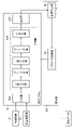
- FIG. 1 is a block diagram showing an example of the configuration of a machine learning system.
- FIG. 2 is a block diagram showing main functions implemented by a processor in a machine learning system.
- FIG. 3 is a diagram for explaining a specific data flow of the machine learning system.
- FIG. 4 is a diagram showing an example of an ultrasound image.
- FIG. 5 is a diagram showing a specific example of the storage configuration of the image database.
- FIG. 6 is a diagram showing a specific example of the storage configuration of the graphics database.
- FIG. 7 is a diagram showing an example of a synthesized image synthesized by the figure synthesizing unit.
- FIG. 8 is a diagram showing an example of a synthesized image synthesized by the figure synthesizing unit.
- FIG. 1 is a block diagram showing an example of the configuration of a machine learning system.
- FIG. 2 is a block diagram showing main functions implemented by a processor in a machine learning system.
- FIG. 3 is a diagram for explaining a
- FIG. 9 is a diagram showing an example of a synthesized image synthesized by the figure synthesizing unit.
- FIG. 10 is a diagram showing an example of a synthesized image synthesized by the graphic synthesizing unit.
- FIG. 11 is a functional block diagram showing main functions of the learning section and the learning model.
- FIG. 12 is a flow diagram illustrating a learning method performed using a machine learning system.
- FIG. 13 is a diagram illustrating a specific data flow of the machine learning system 10 of this embodiment.
- FIG. 14 is a functional block diagram showing main functions of the learning section and the learning model.
- FIG. 15 is a flow diagram illustrating a learning method performed using a machine learning system.
- FIG. 16 is a diagram conceptually explaining an example of learning data.
- FIG. 17 is a schematic diagram showing the overall configuration of an ultrasonic endoscope system.
- FIG. 18 is a block diagram illustrating an embodiment of an ultrasound processor.
- FIG. 1 is a block diagram showing an example of the configuration of the machine learning system of this embodiment.
- the machine learning system 10 is configured by a personal computer or workstation.
- the machine learning system 10 includes a communication unit 12, an image database (described as image DB in the figure) 14, a graphic database (described as graphic DB in the figure) 16, an operation unit 20, a processor 22, a RAM (random access memory) 24, and a ROM. (Read Only Memory) 26 , display unit 28 , and learning model 30 .
- Each unit is connected via a bus 32 .
- an example of being connected to the bus 32 has been described, but the example of the machine learning system 10 is not limited to this.
- part or all of the machine learning system 10 may be connected via a network.
- the network includes various communication networks such as LAN (Local Area Network), WAN (Wide Area Network), and the Internet.
- LAN Local Area Network
- WAN Wide Area Network
- the Internet the machine learning system 10 will be described in this example, the present invention is also applicable to machine learning devices.
- the communication unit 12 is an interface that performs wired or wireless communication processing with an external device and exchanges information with the external device.
- the ROM 26 permanently holds programs such as the computer's boot program and BIOS (Basic Input/Output System), data, and so on.
- BIOS Basic Input/Output System
- the RAM 24 temporarily holds programs, data, and the like loaded from the ROM 26 and a separately connected storage device, and has a work area used by the processor 22 to perform various processes.
- the operation unit 20 is an input interface that receives various operational inputs to the machine learning system 10 .
- the operating unit 20 uses a keyboard, mouse, or the like that is wired or wirelessly connected to the computer.
- the processor 22 is composed of a CPU (Central Processing Unit). Various programs stored in the ROM 26 or a hard disk device (not shown) are read, and various processes are executed. RAM 24 is used as a work area for processor 22 . Also, the RAM 24 is used as a storage unit that temporarily stores the read programs and various data. The machine learning system 10 may configure the processor 22 with a GPU (Graphics Processing Unit).
- CPU Central Processing Unit
- ROM 26 Various programs stored in the ROM 26 or a hard disk device (not shown) are read, and various processes are executed.
- RAM 24 is used as a work area for processor 22 . Also, the RAM 24 is used as a storage unit that temporarily stores the read programs and various data.
- the machine learning system 10 may configure the processor 22 with a GPU (Graphics Processing Unit).
- the display unit 28 is an output interface that displays necessary information for the machine learning system 10 .
- Various monitors such as a liquid crystal monitor connectable to a computer are used for the display unit 28 .
- the image database 14 is a database in which multiple medical images are stored.
- a medical image is, for example, an ultrasound image acquired by an ultrasound endoscope system described below.
- the figure database 16 is a database in which a plurality of types of figures are stored.
- a graphic is a graphic used as an aid for diagnosis (or observation) of a region of interest when a doctor observes an ultrasound image, for example.
- the image database 14 and the graphic database 16 are composed of recording media or the cloud. A detailed description of the image database 14 and the graphic database 16 will be given later.
- the learning model 30 is composed of a CNN (Convolutional Neural Network), and machine learning is performed to recognize the position and type of the attention area from the medical image.
- the learning model 30 outputs at least one of the position of the attention area and the type of the attention area as an estimation result.
- the learning model 30 installed in the machine learning system 10 is unlearned, and the machine learning system 10 causes the learning model 30 to perform machine learning to estimate the position of the attention area and the type of the attention area.
- the attention area is, for example, an organ, a lesion, or the like, and is an area that a doctor pays attention to when observing a medical image.
- the type of the attention area is specifically an organ name, a lesion name, a lesion level, etc., and is a classification of the attention area.
- machine learning system 10 may be configured with a plurality of personal computers.
- FIG. 2 is a block diagram showing the main functions that the processor 22 implements in the machine learning system 10.
- the processor 22 mainly includes a selection section 22A, a graphic synthesis section 22B, and a learning section 22C.
- the selection unit 22A performs selection acceptance processing and accepts selection of medical images stored in the image database 14 .
- the selection unit 22A also accepts selection of a graphic stored in the graphic database 16 .
- the user selects a medical image stored in the image database 14 and a figure stored in the figure database 16 via the operation unit 20, and the selection unit 22A receives the selection.
- the selection unit 22A also performs a size reception process and receives the size of the figure to be synthesized in the figure synthesis process.
- the selection unit 22A also accepts selection of the size of the figure to be combined together with acceptance of the selection of the figure.
- the figure synthesizing unit 22B performs figure synthesizing processing to synthesize the selected medical image and figure to generate a synthesized image.
- the figure synthesizing unit 22B superimposes a figure on a medical image to generate a synthesized image in various ways.
- the figure synthesizing unit 22B can superimpose a figure on the region of interest of the medical image and synthesize them to generate a synthesized image.
- the figure synthesizing unit 22B can generate a synthesized image by superimposing and synthesizing figures so as to exclude the attention area of the medical image.
- the figure synthesizing unit 22B can superimpose and synthesize a figure on a medical image (randomly) regardless of the region of interest.
- the figure synthesizing unit 22B can use, for example, a random number table to determine the position where the figure is to be superimposed, and randomly superimpose the figure on the medical image for synthesis.
- the selection unit 22A accepts the size of the figure, the figure is combined with the medical image based on the size accepted in the size acceptance process.
- the graphic synthesizing unit 22B may generate a plurality of synthesized images by changing the position and size of the selected graphic. That is, the graphic synthesizing unit 22B may change the superimposed position of the selected graphic in the medical image or the size of the selected graphic to generate a plurality of variations of the composite image. This makes it possible to easily generate more learning data.
- the figure synthesizing unit 22B determines the synthesizing mode of the synthetic image by user's designation or automatically, and generates the synthetic image.
- the learning unit 22C performs learning processing and makes the learning model 30 perform learning using the synthesized image. Specifically, the learning unit 22C optimizes the parameters of the learning model 30 based on the error between the estimation result output by the learning model 30 after receiving the synthetic image and the correct data. A detailed description of the learning unit 22C will be given later.
- FIG. 3 is a diagram explaining the specific data flow of the machine learning system 10.
- FIG. 3 an ultrasound image is used as an example of a medical image.
- the selection unit 22A selects the ultrasound image P1 from the image database 14 according to the user's selection. For example, the user selects the ultrasonic image P1 via the operation unit 20. FIG. In addition, the selection unit 22A selects one or a plurality of graphics Q from the graphics database 16 according to the user's selection. Specific examples of the image database 14 and the graphic database 16 will be described below.
- FIG. 4 is a diagram showing an example of an ultrasound image P1 stored in the image database 14.
- FIG. 4 is a diagram showing an example of an ultrasound image P1 stored in the image database 14.
- the ultrasound image P1 has a region of interest showing an organ or lesion. Specifically, the ultrasound image P1 has an attention area T1, an attention area T2, an attention area T3, and an attention area T4.
- the attention area T1 is the image of the organ A
- the attention area T2 is the image of the organ B
- the attention area T3 is the lesion C image
- the attention area T4 is the lesion D image.
- FIG. 5 is a diagram showing a specific example of the storage configuration of the image database 14. As shown in FIG.
- the image database 14 stores a plurality of ultrasound images P. Each ultrasonic image P is assigned an image ID.
- the image ID of the ultrasound image P1 is 001.
- the positions of the regions of interest T1 to T4 of the ultrasonic image P1 are stored in XY coordinates in association with the image ID of the ultrasonic image P1.
- the size of each of the attention areas T1 to T4 is stored in terms of the number of pixels.
- the types of the attention areas T1 to T4 are shown. Note that some or all of the position of the attention area, the size of the attention area, and the type of the attention area stored in the image database 14 in association with the image ID are used in the learning model 30 described later. is used as correct data F in machine learning corresponding to the estimation result output by .
- the image database 14 similarly stores a plurality of ultrasonic images P in addition to the ultrasonic image P1.
- FIG. 6 is a diagram showing a specific example of the storage configuration of the graphic database 16. As shown in FIG.
- the graphic ID, the graphic, the minimum value of the graphic, the maximum value of the graphic, and the area that can be combined are associated and registered.
- the arrow has a graphic ID of 001, a minimum graphic value of 32 px, and a maximum graphic value of 512 px, and the area that can be synthesized is the entire ultrasonic image.
- the line has a graphic ID of 002, a minimum graphic value of 8 px and a maximum graphic value of 960 px, and the area that can be synthesized is within the attention area of the ultrasonic image.
- the rectangle has a graphic ID 003, a minimum graphic value of 64 px and a maximum graphic value of 256 px, and the area that can be combined is the entire area.
- the circle indicates the figure ID 004, the minimum figure value is 16px, the maximum figure value is 256px, and the area that can be combined is the entire area.
- a triangle has a figure ID of 005, a minimum figure value of 128 px, and a maximum figure value of 512 px.
- the graphic database 16 stores graphics other than the graphics described above.
- the ultrasonic image P1 selected by the selection unit 22A and the selected figure Q are input to the figure synthesizing unit 22B.
- the graphic synthesizing unit 22B generates a composite image C from the ultrasonic image P1 and the graphic Q.
- FIG. A specific example of the composite image C will be described below.
- FIG. 7 to 10 are diagrams showing examples of synthesized images synthesized by the graphic synthesizing unit 22B.
- an ultrasound image P1, a figure (arrow) Q1, and a figure (line) Q2 are selected and combined to generate a composite image C1.
- the graphic Q1 is superimposed in the vicinity of the attention area T3 so as to point to the attention area. It is also, in the synthesized image C1, based on the information (X2, Y2) regarding the position of the attention area T2 and/or the information (Z2px) regarding the size of the attention area, a figure Q2 is superimposed so as to indicate both ends of the attention area T2. It is In this way, the synthesized image C1 is generated by superimposing the graphic Q1 and the graphic Q2 on the ultrasonic image P1 so that the doctor actually observes the ultrasonic image P1.
- an ultrasound image P1 and a figure (rectangle) Q3 are selected, and a synthesized image C2 is generated by synthesizing them.
- the figure Q3 is superimposed so that the attention areas T3 and T4 are included in the rectangle, and , a part of the figure Q3 crosses the attention area T1 and the attention area T2.
- the composite image C2 is generated by superimposing the graphic Q3 on the ultrasound image P1 so that the doctor can attach the composite image C1 as an aid when observing the regions of interest T3 and T4.
- an ultrasound image P1 and a graphic (rectangle) Q5 are selected, and a composite image C3 is generated by combining them.
- the superimposition position is determined using a random number table or the like, and the figure Q5 is randomly superimposed.
- the doctor indicates a region of interest (for example, surrounds the region of interest with a rectangle or indicates the region of interest with an arrow), but in the case shown in FIG.
- Graphic Q5 is superimposed independently of T4.
- the graphic Q5 is superimposed on the ultrasound image P1 in a manner different from the way the doctor attaches the graphic (regardless of the position of the region of interest).
- an ultrasonic image P1 a figure (arrow) Q6, a figure (line) Q7, a figure (line) Q8 and a figure (arrow) Q9 are selected, and by synthesizing these, a synthesized image C4 is obtained. generated.
- the graphic Q6 and the graphic Q8 are superimposed so as to exclude the attention areas T1-T4 based on the information (see FIG. 5) on the positions and/or sizes of the attention areas T1-T4.
- the graphic Q7 and the graphic Q9 are randomly arranged.
- the figures Q6 to Q9 are randomly superimposed on the synthesized image C4, and the figures Q6 to Q9 are displayed in a different form from the case where the doctor attaches figures to the ultrasound image (irrespective of the position of the region of interest). is superimposed on the ultrasonic image P1.
- the synthesized image C synthesized by the graphic synthesizing unit 22B is input to the learning model 30. Further, the position of the attention area and the type of the attention area of the ultrasonic image P1 selected by the selection unit 22A are input as correct data F to the learning unit 22C. Machine learning of the learning model 30 by the learning unit 22C will be described below.
- FIG. 11 is a functional block diagram showing main functions of the learning unit 22C and the learning model 30.
- FIG. 22 C of learning parts are provided with the error calculation part 54 and the parameter update part 56.
- FIG. Further, the correct answer data F is input to the learning section 22C.
- the learning model 30 is a recognizer that recognizes the position of the attention area in the ultrasound image P and the type of the attention area.
- the learning model 30 has a multiple layer structure and holds multiple weight parameters.
- the learning model 30 changes from an unlearned model to a learned model by updating the weight parameter from the initial value to the optimum value.
- This learning model 30 comprises an input layer 52A, an intermediate layer 52B, and an output layer 52C.
- the input layer 52A, the intermediate layer 52B, and the output layer 52C each have a structure in which a plurality of "nodes" are connected by "edges.”
- a composite image C to be learned is input to the input layer 52A.
- the intermediate layer 52B is a layer that extracts features from the image input from the input layer 52A.
- the intermediate layer 52B has multiple sets of convolutional layers and pooling layers, and a fully connected layer.
- the convolution layer performs a filtered convolution operation on nearby nodes in the previous layer to obtain a feature map.
- the pooling layer reduces the feature map output from the convolution layer to a new feature map.
- a fully connected layer connects all of the nodes of the immediately preceding layer (here the pooling layer).
- the convolution layer plays a role of feature extraction such as edge extraction from an image, and the pooling layer plays a role of providing robustness so that the extracted features are not affected by translation or the like.
- the intermediate layer 52B is not limited to the case where the convolution layer and the pooling layer are set as one set, but also includes the case where the convolution layers are continuous and the normalization layer.
- the output layer 52C is a layer that outputs recognition results of the position and type of the region of interest in the ultrasonic image P based on the features extracted by the intermediate layer 52B.
- the trained learning model 30 outputs the recognition result of the position and type of the attention area.
- Arbitrary initial values are set for the coefficients of the filters applied to each convolutional layer of the learning model 30 before learning, the offset value, and the weight of the connection with the next layer in the fully connected layer.
- the error calculation unit 54 acquires the recognition result output from the output layer 52C of the learning model 30 and the correct data F for the input image, and calculates the error between them. Error calculation methods include, for example, softmax cross entropy, or MSE: Mean Squared Error.
- the correct data F of the input image (composite image C1) is, for example, data indicating the positions and types of the attention areas T1 to T4.
- the parameter updating unit 56 adjusts the weight parameters of the learning model 30 by error backpropagation based on the error calculated by the error calculating unit 54.
- This parameter adjustment process is repeated, and learning is repeated until the difference between the output of the learning model 30 and the correct data F becomes small.
- the learning unit 22C optimizes each parameter of the learning model 30 using at least the synthetic image C1 and the data set of the correct data F.
- a mini-batch method may be used in which a fixed number of data sets are extracted, learning is batch-processed using the extracted data sets, and this is repeated.
- Each step of the learning method is performed by the processor 22 executing a program.
- FIG. 12 is a flow diagram explaining a learning method performed using the machine learning system 10.
- the selection unit 22A receives selection of an ultrasonic image (medical image) (selection receiving step: step S10). For example, the user confirms the ultrasound image displayed on the display unit 28 and selects the ultrasound image via the operation unit 20 .
- the selection unit 22A accepts selection of a figure (selection step: step S11). For example, the user confirms the graphics displayed on the display unit 28 and selects the graphics via the operation unit 20 . In this case, the size of the selected figure may also be selected, and the figure may be superimposed and synthesized according to the selected size.
- the graphic synthesizing unit 22B synthesizes the selected ultrasonic image and the selected graphic to generate a synthesized image (graphic synthesizing step: step S12).
- the learning unit 22C causes the learning model 30 to perform machine learning using the synthesized image (learning step: step S13).
- a medical image stored in the image database 14 and a figure stored in the figure database 16 are selected, and a composite image is generated from the medical image and the figure. be done.
- the learning model 30 is trained using the synthesized image, so that a large number of synthesized medical images can be learned efficiently and easily.
- the selected ultrasound images are used for machine learning at least twice.
- the first ultrasound image with no synthesized graphics and the second ultrasound image with synthesized graphics are used for machine learning.
- FIG. 13 is a diagram explaining the specific data flow of the machine learning system 10 of this embodiment.
- symbol is attached
- the synthetic image C and the ultrasound image P1 are input to the learning model 30 .
- the learning model 30 outputs an estimation result for each input image.
- the learning model 30 receives the synthesized image C and outputs the estimation result, and receives the ultrasonic image P1 and outputs the estimation result.
- FIG. 14 is a functional block diagram showing main functions of the learning unit 22C and the learning model 30 of this embodiment. 11 are given the same reference numerals, and description thereof will be omitted.
- machine learning is performed using the composite image C1 and the ultrasound image P1.
- the composite image C1 and the ultrasound image P1 are input to the input layer 52A.
- the learning model 30 outputs an estimation result for the synthetic image C1.
- the ultrasonic image P1 is input, the learning model 30 outputs an estimation result for the ultrasonic image P1.
- the error between the estimation result and the correct data F is calculated, and the parameters are updated by the parameter updating unit 56 based on the error.
- the ultrasonic image P1 is input to the learning model 30, and the position and type of the attention area are estimated and output from the output layer 52C.
- the error between the estimation result and the correct data is calculated, and the parameters are updated by the parameter updating unit 56 based on the error.
- the correct data F is data indicating the position and type of the attention area of the ultrasonic image P1, it can be used in common in the machine learning of the composite image C1 and the ultrasonic image P1.
- FIG. 15 is a flow chart explaining a learning method performed using the machine learning system 10.
- the selection unit 22A accepts selection of an ultrasound image (step S20).
- the selection unit 22A accepts selection of a figure (step S21).
- the graphic synthesizing unit 22B synthesizes the selected ultrasonic image and the selected graphic to generate a synthesized image (step S22).
- the learning unit 22C causes the learning model 30 to perform machine learning using the synthesized image. (Step S23). After that, the learning unit 22C causes the learning model 30 to perform machine learning using the ultrasound images that have not been synthesized (step S24).
- machine learning is performed using a synthesized image and an ultrasound image in which graphics are not synthesized. How to use synthetic images and ultrasound images for machine learning will be described below.
- FIG. 16 is a diagram conceptually explaining an example of learning data of the present invention.
- FIG. 16(A) shows learning data used in the first embodiment.
- the first embodiment since synthetic images are used as training data, mini-batches made up of synthetic images are prepared.
- training data for A batch 80, B batch 82, C batch 84, D batch 86, and E batch 88 are prepared, and each batch is composed of, for example, 200 synthesized images. be. Therefore, in one epoch, the A batch 80, the B batch 82, the C batch 84, the D batch 86, and the E batch 88 are all input to the learning model 30, and machine learning is performed.
- FIG. 16(B) shows learning data used in the second embodiment.
- mini-batches each composed of synthesized images and ultrasound images are prepared.
- batch A 80, batch a 90, batch B 82, batch b 92, batch C 84, batch c 94, batch D 86, batch d 96, batch E 88, batch e 98 training data is prepared.
- Each of the A batch 80, B batch 82, C batch 84, D batch 86, and E batch 88 is composed of, for example, 200 composite images.
- each of the a-batch 90, b-batch 92, c-batch 94, d-batch 96, and e-batch 98 is composed of, for example, 200 ultrasound images.
- the same ultrasonic image is used for the A batch 80 and the a batch 90 .
- the ultrasound images used for the synthesized images that make up the A batch 80 make up the a batch 90, and the same applies to the other batches.
- the learning model 30 goes through A batch 80, a batch 90, B batch 82, b batch 92, C batch 84, c batch 94, D batch 86, d batch 96, E batch 88, and e batch 98. , and machine learning is performed.
- FIG. 16(C) shows another example of learning data used in the second embodiment.
- a first epoch composed of A batch 80, B batch 82, C batch 84, D batch 86, and E batch 88, and a batch 90, b batch 92, and c batch.
- a second epoch consisting of 94, d-batch 96, and e-batch 98 is performed. Note that the same ultrasonic image is used for the A batch 80 and the a batch 90, as described with reference to FIG. 16B.
- the combined image and the uncombined ultrasound image are used as learning data. Learning of the learning model 30 to recognize can be performed more effectively.
- a recognizer composed of a trained model machine-learned by the machine-learning system 10 described above will be described. This recognizer is installed in an ultrasonic endoscope system.
- FIG. 17 is a schematic diagram showing the overall configuration of an ultrasonic endoscope system (ultrasonic diagnostic apparatus) including a learning model 30 (learned model) for which machine learning has been completed by the above-described machine learning system 10 as a recognizer 206. be.
- a learning model 30 learned model
- the ultrasonic endoscope system 102 includes an ultrasonic scope 110, an ultrasonic processor device 112 that generates ultrasonic images, and an endoscope processor device 114 that generates endoscopic images. , a light source device 116 for supplying illumination light for illuminating the inside of the body cavity to the ultrasound scope 110, and a monitor 118 for displaying ultrasound images and endoscopic images.
- the ultrasonic scope 110 includes an insertion section 120 to be inserted into the body cavity of the subject, a hand operation section 122 connected to the proximal end of the insertion section 120 and operated by the operator, and one end of the hand operation section 122. and a universal cord 124 to which is connected.
- the other end of the universal cord 124 is connected to an ultrasonic connector 126 connected to the ultrasonic processor device 112 , an endoscope connector 128 connected to the endoscope processor device 114 , and a light source device 116 .
- a light source connector 130 is provided.
- the ultrasound scope 110 is detachably connected to the ultrasound processor device 112, the endoscope processor device 114 and the light source device 116 via these connectors 126, 128 and 130, respectively. Further, an air/water supply tube 132 and a suction tube 134 are connected to the light source connector 130 .
- the monitor 118 receives each video signal generated by the ultrasound processor device 112 and the endoscope processor device 114 and displays an ultrasound image and an endoscopic image.
- the display of the ultrasonic image and the endoscopic image it is possible to display only one of the images on the monitor 118 by appropriately switching between them, or to display both images at the same time.
- the hand operation unit 122 is provided with an air/water supply button 136 and a suction button 138 side by side, as well as a pair of angle knobs 142 and a treatment instrument insertion port 144 .
- the insertion portion 120 has a distal end, a proximal end, and a longitudinal axis 120a, and includes, in order from the distal end side, a distal portion main body 150 made of a hard member, and a bending portion connected to the proximal end side of the distal portion main body 150. 152, and an elongated flexible flexible portion 154 that connects between the base end side of the bending portion 152 and the distal end side of the hand operation portion 122.
- the distal end portion main body 150 is provided on the distal end side of the insertion portion 120 in the direction of the longitudinal axis 120a.
- the bending portion 152 is remotely operated to bend by rotating a pair of angle knobs 142 provided on the hand operation portion 122 . This allows the tip body 150 to be oriented in a desired direction.
- An ultrasonic probe 162 and a bag-like balloon 164 covering the ultrasonic probe 162 are attached to the tip body 150 .
- the balloon 164 can be inflated or deflated by being supplied with water from the water supply tank 170 or by sucking the water in the balloon 164 with the suction pump 172 .
- the balloon 164 is inflated until it abuts against the inner wall of the body cavity in order to prevent attenuation of ultrasonic waves and ultrasonic echoes (echo signals) during ultrasonic observation.
- an endoscope observation section (not shown) having an observation section having an objective lens, an imaging device, and the like, and an illumination section is attached to the distal end body 150 .
- the endoscope observation section is provided behind the ultrasonic probe 162 (on the side of the hand operation section 122).
- FIG. 18 is a block diagram showing an embodiment of an ultrasound processor.
- the ultrasound processor device 112 shown in FIG. 18 recognizes the position and type of the region of interest in the ultrasound image based on the sequentially acquired time-series ultrasound images, and notifies the user of information indicating the recognition result. It is.
- the ultrasound processor device 112 shown in FIG. 18 is composed of a transmission/reception unit 200, an image generation unit 202, a CPU (Central Processing Unit) 204, a recognizer 206, a display control unit 210, and a memory 212. Implemented by one or more processors. Note that the recognizer 206 is loaded with the learning model 30 trained by the above-described machine learning system 10 while holding the parameters as they are.
- the CPU 204 operates based on various programs including the ultrasonic image processing program according to the present invention stored in the memory 212, and controls the transmission/reception unit 200, the image generation unit 202, the recognizer 206, and the display control unit 210. and functions as part of each of these units.
- the transmitting/receiving unit 200 and the image generating unit 202 sequentially acquire time-series ultrasound images.
- a transmission unit of the transmission/reception unit 200 generates a plurality of drive signals to be applied to a plurality of ultrasonic transducers of the ultrasonic probe 162 of the ultrasonic scope 110, and based on a transmission delay pattern selected by a scanning control unit (not shown). to apply the plurality of drive signals to the plurality of ultrasonic transducers by giving respective delay times to the plurality of drive signals.
- the receiving unit of the transmitting/receiving unit 200 amplifies a plurality of detection signals respectively output from the plurality of ultrasonic transducers of the ultrasonic probe 162, converts the analog detection signals into digital detection signals (also known as RF (Radio Frequency) data). ). This RF data is input to the image generator 202 .
- the image generation unit 202 Based on the reception delay pattern selected by the scanning control unit, the image generation unit 202 gives a delay time to each of the plurality of detection signals represented by the RF data, and adds the detection signals to obtain a reception focus. process.
- This reception focusing process forms sound ray data in which the focus of the ultrasonic echo is narrowed down.
- the image generation unit 202 further corrects attenuation due to distance according to the depth of the reflection position of the ultrasonic wave by STC (Sensitivity Timegain Control) for the sound ray data, and then performs envelope detection processing using a low-pass filter or the like.
- Envelope data for one frame, preferably a plurality of frames, is stored in a cine memory (not shown).
- the image generating unit 202 performs preprocessing such as log (logarithmic) compression and gain adjustment on the envelope data stored in the cine memory to generate a B-mode image.
- the transmitting/receiving unit 200 and the image generating unit 202 sequentially acquire time-series B-mode images (hereinafter referred to as "ultrasound images").
- the recognizer 206 performs a process of recognizing information about the position of a region of interest in the ultrasonic image based on the ultrasonic image, and classifies the region of interest into one of a plurality of classes (types) based on the ultrasonic image. It performs the process of classifying into The recognizer 206 is composed of a trained model, and machine learning is performed by the machine learning system 10 described above.
- the regions of interest in this example are various organs in the ultrasound image (B-mode image tomographic image), such as the pancreas, main pancreatic duct, spleen, splenic vein, splenic artery, gallbladder, and the like.
- the recognizer 206 recognizes the position of the attention area for each input ultrasound image, outputs information about the position, and recognizes the attention area as one of a plurality of classes. and output information indicating the recognized class (class information).
- the position of the attention area can be, for example, the center position of a rectangle surrounding the attention area.
- the class information is information indicating the type of organ in this example.
- the display control unit 210 includes a first display control unit 210A that displays time-series ultrasound images on the monitor 118, which is a display unit, and a second display control unit 210B that causes the monitor 118 to display information about the attention area. ing.
- the first display control unit 210A causes the monitor 118 to display the ultrasound images sequentially acquired by the transmission/reception unit 200 and the image generation unit 202 .
- a moving image showing an ultrasonic tomographic image is displayed on the monitor 118 .
- the first display control unit 210A performs reception processing for receiving a phrase command from the hand operation unit 122 of the ultrasonic scope 110. For example, when the freeze button of the hand operation unit 122 is operated and a freeze instruction is received, the monitor 118 The sequential display of the ultrasonic images displayed in 1 is switched to the fixed display of one ultrasonic image (current ultrasonic image).
- the second display control unit 210B superimposes and displays the class information indicating the classification of the attention area recognized by the recognizer 206 at the position of the attention area of the ultrasound image displayed on the monitor 118 .
- the relative position of the class information with respect to the attention area is also fixed while the ultrasonic image displayed on the monitor 118 is fixedly displayed as a still image.
- the learning model 30 machine-learned by the machine-learning system 10 is used as the recognizer 206 .
- the recognizer 206 it is possible to accurately recognize the region of interest appearing in the ultrasonic image.
- the hardware structure of the processing unit (for example, the selection unit 22A, the graphic synthesis unit 22B, and the learning unit 22C) (processing unit) that executes various processes includes various processors ( processor).
- processors processors
- the circuit configuration can be changed after manufacturing such as CPU (Central Processing Unit), which is a general-purpose processor that executes software (program) and functions as various processing units, FPGA (Field Programmable Gate Array), etc.
- Programmable Logic Device which is a processor, ASIC (Application Specific Integrated Circuit), etc. be
- One processing unit may be composed of one of these various processors, or composed of two or more processors of the same type or different types (for example, a plurality of FPGAs, or a combination of a CPU and an FPGA).
- a plurality of processing units may be configured by one processor.
- a processor functions as multiple processing units.
- SoC System On Chip
- SoC System On Chip
- the hardware structure of these various processors is, more specifically, an electrical circuit that combines circuit elements such as semiconductor elements.
- machine learning system 12 communication unit 14: image database 16: graphic database 20: operation unit 22: processor 22A: selection unit 22B: graphic synthesis unit 22C: learning unit 24: RAM 26: ROM 28: display unit 30: learning model 32: bus
Landscapes
- Engineering & Computer Science (AREA)
- Health & Medical Sciences (AREA)
- Theoretical Computer Science (AREA)
- Physics & Mathematics (AREA)
- General Health & Medical Sciences (AREA)
- Medical Informatics (AREA)
- General Physics & Mathematics (AREA)
- Public Health (AREA)
- Biomedical Technology (AREA)
- Software Systems (AREA)
- Evolutionary Computation (AREA)
- Data Mining & Analysis (AREA)
- Artificial Intelligence (AREA)
- Computing Systems (AREA)
- Life Sciences & Earth Sciences (AREA)
- Databases & Information Systems (AREA)
- Computer Vision & Pattern Recognition (AREA)
- Radiology & Medical Imaging (AREA)
- Nuclear Medicine, Radiotherapy & Molecular Imaging (AREA)
- Primary Health Care (AREA)
- Molecular Biology (AREA)
- Biophysics (AREA)
- Epidemiology (AREA)
- Multimedia (AREA)
- Computational Linguistics (AREA)
- Mathematical Physics (AREA)
- General Engineering & Computer Science (AREA)
- Pathology (AREA)
- Quality & Reliability (AREA)
- Heart & Thoracic Surgery (AREA)
- Surgery (AREA)
- Animal Behavior & Ethology (AREA)
- Veterinary Medicine (AREA)
- Image Analysis (AREA)
- Ultra Sonic Daignosis Equipment (AREA)
- Image Processing (AREA)
Priority Applications (2)
| Application Number | Priority Date | Filing Date | Title |
|---|---|---|---|
| JP2023503803A JP7803922B2 (ja) | 2021-03-01 | 2022-02-28 | 機械学習システム、学習方法、学習済みモデル、プログラム及び記録媒体 |
| US18/457,374 US12511879B2 (en) | 2021-03-01 | 2023-08-29 | Machine learning system, recognizer, learning method, and program |
Applications Claiming Priority (2)
| Application Number | Priority Date | Filing Date | Title |
|---|---|---|---|
| JP2021031699 | 2021-03-01 | ||
| JP2021-031699 | 2021-03-01 |
Related Child Applications (1)
| Application Number | Title | Priority Date | Filing Date |
|---|---|---|---|
| US18/457,374 Continuation US12511879B2 (en) | 2021-03-01 | 2023-08-29 | Machine learning system, recognizer, learning method, and program |
Publications (1)
| Publication Number | Publication Date |
|---|---|
| WO2022186110A1 true WO2022186110A1 (ja) | 2022-09-09 |
Family
ID=83153756
Family Applications (1)
| Application Number | Title | Priority Date | Filing Date |
|---|---|---|---|
| PCT/JP2022/008167 Ceased WO2022186110A1 (ja) | 2021-03-01 | 2022-02-28 | 機械学習システム、認識器、学習方法、及びプログラム |
Country Status (3)
| Country | Link |
|---|---|
| US (1) | US12511879B2 (https=) |
| JP (1) | JP7803922B2 (https=) |
| WO (1) | WO2022186110A1 (https=) |
Cited By (1)
| Publication number | Priority date | Publication date | Assignee | Title |
|---|---|---|---|---|
| JP7592789B1 (ja) | 2023-06-22 | 2024-12-02 | ジーイー・プレシジョン・ヘルスケア・エルエルシー | 学習済みモデルの生産方法、超音波診断装置及び、学習済みモデルを生産する装置 |
Families Citing this family (1)
| Publication number | Priority date | Publication date | Assignee | Title |
|---|---|---|---|---|
| US20240000511A1 (en) * | 2022-07-01 | 2024-01-04 | Peter Andrew Flaherty | Visually positioned surgery |
Citations (5)
| Publication number | Priority date | Publication date | Assignee | Title |
|---|---|---|---|---|
| WO2016157499A1 (ja) * | 2015-04-02 | 2016-10-06 | 株式会社日立製作所 | 画像処理装置、物体検知装置、画像処理方法 |
| JP2019087078A (ja) * | 2017-11-08 | 2019-06-06 | オムロン株式会社 | データ生成装置、データ生成方法及びデータ生成プログラム |
| WO2020075531A1 (ja) * | 2018-10-10 | 2020-04-16 | 株式会社島津製作所 | 画像作成装置、画像作成方法および学習済みモデルの作成方法 |
| JP2021005266A (ja) * | 2019-06-27 | 2021-01-14 | 株式会社Screenホールディングス | 画像判別モデル構築方法、画像判別モデル、および画像判別方法 |
| JP2021013685A (ja) * | 2019-07-16 | 2021-02-12 | 富士フイルム株式会社 | 放射線画像処理装置、方法およびプログラム |
Family Cites Families (5)
| Publication number | Priority date | Publication date | Assignee | Title |
|---|---|---|---|---|
| US10964017B2 (en) * | 2018-11-15 | 2021-03-30 | General Electric Company | Deep learning for arterial analysis and assessment |
| KR102258776B1 (ko) * | 2019-05-20 | 2021-05-31 | 주식회사 힐세리온 | 인공지능형 초음파 지방간 자동 진단 장치 및 이를 이용한 원격 의료 진단 방법 |
| JP7313192B2 (ja) | 2019-05-27 | 2023-07-24 | キヤノンメディカルシステムズ株式会社 | 診断支援装置、及び、x線ct装置 |
| CN110728674B (zh) * | 2019-10-21 | 2022-04-05 | 清华大学 | 图像处理方法及装置、电子设备和计算机可读存储介质 |
| CN111341419A (zh) * | 2020-02-19 | 2020-06-26 | 京东方科技集团股份有限公司 | 医学图像的处理方法、装置、系统、控制系统及存储介质 |
-
2022
- 2022-02-28 WO PCT/JP2022/008167 patent/WO2022186110A1/ja not_active Ceased
- 2022-02-28 JP JP2023503803A patent/JP7803922B2/ja active Active
-
2023
- 2023-08-29 US US18/457,374 patent/US12511879B2/en active Active
Patent Citations (5)
| Publication number | Priority date | Publication date | Assignee | Title |
|---|---|---|---|---|
| WO2016157499A1 (ja) * | 2015-04-02 | 2016-10-06 | 株式会社日立製作所 | 画像処理装置、物体検知装置、画像処理方法 |
| JP2019087078A (ja) * | 2017-11-08 | 2019-06-06 | オムロン株式会社 | データ生成装置、データ生成方法及びデータ生成プログラム |
| WO2020075531A1 (ja) * | 2018-10-10 | 2020-04-16 | 株式会社島津製作所 | 画像作成装置、画像作成方法および学習済みモデルの作成方法 |
| JP2021005266A (ja) * | 2019-06-27 | 2021-01-14 | 株式会社Screenホールディングス | 画像判別モデル構築方法、画像判別モデル、および画像判別方法 |
| JP2021013685A (ja) * | 2019-07-16 | 2021-02-12 | 富士フイルム株式会社 | 放射線画像処理装置、方法およびプログラム |
Non-Patent Citations (1)
| Title |
|---|
| MAHAPATRA SMRUTI; BALAMURUGAN MANISH; CHUNG KATHRYN; KUPPOOR VENKAT; CURRY ELI; AGHABAGLOU FARIBA; PARVEZ KAOVASIA TARANA; ACORD M: "Automatic detection of cotton balls during brain surgery: where deep learning meets ultrasound imaging to tackle foreign objects", PROGRESS IN BIOMEDICAL OPTICS AND IMAGING, SPIE - INTERNATIONAL SOCIETY FOR OPTICAL ENGINEERING, BELLINGHAM, WA, US, vol. 11602, 26 February 2021 (2021-02-26), BELLINGHAM, WA, US , pages 116021C - 116021C-8, XP060139893, ISSN: 1605-7422, ISBN: 978-1-5106-0027-0, DOI: 10.1117/12.2580887 * |
Cited By (2)
| Publication number | Priority date | Publication date | Assignee | Title |
|---|---|---|---|---|
| JP7592789B1 (ja) | 2023-06-22 | 2024-12-02 | ジーイー・プレシジョン・ヘルスケア・エルエルシー | 学習済みモデルの生産方法、超音波診断装置及び、学習済みモデルを生産する装置 |
| JP2025002440A (ja) * | 2023-06-22 | 2025-01-09 | ジーイー・プレシジョン・ヘルスケア・エルエルシー | 学習済みモデルの生産方法、超音波診断装置及び、学習済みモデルを生産する装置 |
Also Published As
| Publication number | Publication date |
|---|---|
| JP7803922B2 (ja) | 2026-01-21 |
| US12511879B2 (en) | 2025-12-30 |
| US20230410482A1 (en) | 2023-12-21 |
| JPWO2022186110A1 (https=) | 2022-09-09 |
Similar Documents
| Publication | Publication Date | Title |
|---|---|---|
| US11436729B2 (en) | Medical image processing apparatus | |
| CN111035408B (zh) | 用于超声探头定位反馈的增强的可视化的方法和系统 | |
| US9161741B2 (en) | Ultrasonic image processing apparatus, ultrasonic diagnostic apparatus, and ultrasonic image processing method | |
| US9173632B2 (en) | Ultrasonic diagnosis system and image data display control program | |
| JP7218425B2 (ja) | 超音波内視鏡システムおよび超音波内視鏡システムの作動方法 | |
| JP5486432B2 (ja) | 画像処理装置、その作動方法およびプログラム | |
| US11883241B2 (en) | Medical image diagnostic apparatus, ultrasonic diagnostic apparatus, medical imaging system, and imaging control method | |
| US12558068B2 (en) | Medical image processing apparatus, endoscope system, medical image processing method, and medical image processing program | |
| US20220358750A1 (en) | Learning device, depth information acquisition device, endoscope system, learning method, and program | |
| US12511879B2 (en) | Machine learning system, recognizer, learning method, and program | |
| WO2017104627A1 (ja) | 超音波観測装置、超音波観測装置の作動方法および超音波観測装置の作動プログラム | |
| JP7158596B2 (ja) | 超音波内視鏡システムおよび超音波内視鏡システムの作動方法 | |
| US12548283B2 (en) | Medical image processing apparatus, method, and program | |
| JP7292184B2 (ja) | 学習装置、学習方法および学習済みモデル | |
| US20120095341A1 (en) | Ultrasonic image processing apparatus and ultrasonic image processing method | |
| CN121337397A (zh) | 一种基于心脏表面的超声成像系统、方法、介质及产品 | |
| JP7190316B2 (ja) | 超音波診断装置、超音波撮像プログラム、及び超音波撮像方法 | |
| JP2004209277A (ja) | 超音波画像診断装置 | |
| JP6530660B2 (ja) | 超音波観測装置、超音波観測装置の作動方法および超音波観測装置の作動プログラム | |
| US12608859B2 (en) | Moving image processing apparatus, moving image processing method and program, and moving image display system for displaying information related to an object in the moving image | |
| WO2022234742A1 (ja) | 表示処理装置、方法及びプログラム | |
| WO2022239529A1 (ja) | 医療画像処理装置、医療画像処理方法、及びプログラム | |
| JP7662394B2 (ja) | 超音波診断装置、医用画像処理装置、およびプログラム | |
| JP2026074293A (ja) | 内視鏡システム及び内視鏡システムの作動方法、プログラム、並びに記録媒体 | |
| WO2022239530A1 (ja) | 画像処理装置、画像処理システム、画像処理方法、及び画像処理プログラム |
Legal Events
| Date | Code | Title | Description |
|---|---|---|---|
| 121 | Ep: the epo has been informed by wipo that ep was designated in this application |
Ref document number: 22763166 Country of ref document: EP Kind code of ref document: A1 |
|
| WWE | Wipo information: entry into national phase |
Ref document number: 2023503803 Country of ref document: JP |
|
| NENP | Non-entry into the national phase |
Ref country code: DE |
|
| 122 | Ep: pct application non-entry in european phase |
Ref document number: 22763166 Country of ref document: EP Kind code of ref document: A1 |