WO2022185490A1 - 情報処理装置、通信装置、情報処理方法及びプログラム - Google Patents
情報処理装置、通信装置、情報処理方法及びプログラム Download PDFInfo
- Publication number
- WO2022185490A1 WO2022185490A1 PCT/JP2021/008519 JP2021008519W WO2022185490A1 WO 2022185490 A1 WO2022185490 A1 WO 2022185490A1 JP 2021008519 W JP2021008519 W JP 2021008519W WO 2022185490 A1 WO2022185490 A1 WO 2022185490A1
- Authority
- WO
- WIPO (PCT)
- Prior art keywords
- traffic flow
- management information
- flow management
- data frame
- information
- Prior art date
- Legal status (The legal status is an assumption and is not a legal conclusion. Google has not performed a legal analysis and makes no representation as to the accuracy of the status listed.)
- Ceased
Links
Images




Classifications
-
- H—ELECTRICITY
- H04—ELECTRIC COMMUNICATION TECHNIQUE
- H04L—TRANSMISSION OF DIGITAL INFORMATION, e.g. TELEGRAPHIC COMMUNICATION
- H04L47/00—Traffic control in data switching networks
- H04L47/50—Queue scheduling
- H04L47/56—Queue scheduling implementing delay-aware scheduling
-
- H—ELECTRICITY
- H04—ELECTRIC COMMUNICATION TECHNIQUE
- H04L—TRANSMISSION OF DIGITAL INFORMATION, e.g. TELEGRAPHIC COMMUNICATION
- H04L47/00—Traffic control in data switching networks
- H04L47/10—Flow control; Congestion control
- H04L47/28—Flow control; Congestion control in relation to timing considerations
Definitions
- the embodiments of the present invention relate to information processing devices, communication devices, information processing methods, and programs.
- Non-Patent Document 1 discloses a non-instantaneous interruption redundancy switching technique. Ethernet (registered trademark) is generally used for the network.
- Non-Patent Document 1 in a one-to-one transmission/reception configuration, a device that performs non-instantaneous interruption processing (hereinafter referred to as a non-instantaneous interruption device) located at a transmission source site Duplicates the user data frame to be transmitted given from the user terminal at the site. This duplicated frame is transferred from the uninterrupted device through two different routes of the relay network, and reaches the uninterrupted device located at the destination site. The uninterrupted device at the destination site selects one of the identical frames arriving from the two routes and transfers it to the user terminal at the destination site.
- a non-instantaneous interruption device located at a transmission source site
- This duplicated frame is transferred from the uninterrupted device through two different routes of the relay network, and reaches the uninterrupted device located at the destination site.
- the uninterrupted device at the destination site selects one of the identical frames arriving from the two routes and transfers it to the user terminal at the destination site.
- the uninterruptible device at the source gives a sequence number to the frames to be duplicated as traffic flow management information.
- the destination hitless device holds the sequence number of the next frame to be processed in the form of an expected number.
- the destination uninterruptible device waits until the frame with the expected number arrives.
- one-to-n (n ⁇ 2) configuration that is, communication between multiple locations where there are multiple receiving sides
- the route is similarly made redundant for high reliability, and failures can occur. For example, a network service that switches paths without instantaneous interruption by an uninterrupted device is required.
- hitless device A when hitless device A receives a mixture of user data frames addressed to user terminal B and user data frames addressed to user terminal C from user terminal A, hitless device A receives the mixed user data Allocate a sequence number to the frame and send it to the network.
- the uninterruptible device A associates a pair of uninterrupted devices as one traffic flow, assigns a sequence number to each, and transmits it to the network.
- a frame destined for user terminal B is received only by uninterruptible device B, and a frame destined for user terminal C is received by a network switch arranged in the network through MAC address learning in the network switch. It is designed to be received only by the hitless device C.
- the uninterruptible device will also receive data frames addressed to other devices. For this reason, the uninterrupted device needs to reserve more communication resources than necessary, which are the sequence numbers of data frames in a plurality of traffic flows, which leads to an increase in device cost.
- the present invention it is possible to continuously secure resources for communications that should be originally communicated even during flooding without securing communication resources for a non-instantaneous interruption device more than necessary, while waiting for new communications during flooding. It is intended to provide a technique that makes it possible to shorten the time.
- an information processing apparatus in a communication apparatus and includes traffic flow management information necessary for transferring data consisting of multiple frames from a source terminal to a destination terminal.
- is an information processing apparatus that performs management processing of and includes an identification unit, a recording unit, a determination unit, and an extension unit.
- the identifying unit identifies a traffic flow associated with the received data frame based on identification information included in the received data frame.
- the recording unit determines whether or not the number of already recorded traffic flow management information is equal to or greater than a threshold. , calculating and recording the scheduled release time of the traffic flow management information to be newly recorded.
- the determination unit determines whether a traffic flow associated with the received data frame has already been recorded.
- the extension unit sets the scheduled opening time of the traffic flow management information of the traffic flow to the time when the traffic flow management information of the traffic flow is recorded for the first time. is extended according to the determination result of
- FIG. 1 is a block diagram showing an example of a schematic configuration of a communication system to which an embodiment of an information processing apparatus of the invention is applied.
- FIG. 2 is a block diagram showing an example of the functional configuration of a non-instantaneous interruption device having a traffic flow management information processing section as an information processing device according to one embodiment of the present invention.
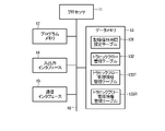
- FIG. 3 is a diagram illustrating an example of a hardware configuration of an uninterrupted device;
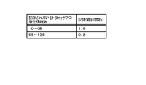
- FIG. 4 is a schematic diagram showing an example of the contents of a record retention time setting table provided in the uninterrupted device.
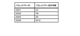
- FIG. 5 is a schematic diagram showing an example of the contents of a traffic flow management table provided in the hitless device.
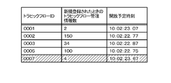
- FIG. 6 is a schematic diagram showing an example of the contents of a traffic flow management information management table provided in the uninterrupted device.
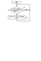
- FIG. 7 is a flow chart showing an example of the processing operation of the traffic flow management information registration process in the traffic flow management information processing section.
- FIG. 8 is a schematic diagram showing an example of the contents of a traffic flow management table when new traffic flow management information is registered.
- FIG. 9 is a schematic diagram showing an example of the contents of the traffic flow management information management table when new traffic flow management information is registered.
- FIG. 10 is a schematic diagram showing an example of the contents of the traffic flow management information management table when the traffic flow management information is extended.
- FIG. 11 is a flow chart showing an example of the processing operation of the traffic flow management information release processing in the traffic flow management information processing unit.
- a communication system multiplexes signals between multiple uninterruptible devices through redundant paths including multiple relay paths.
- the number of relay routes is 2
- the number of uninterruptible devices on the transmitting side is 1
- the number of uninterrupted devices on the receiving side is 2.
- FIG. 1 is a block diagram showing an example of a schematic configuration of a communication system to which an embodiment of an information processing apparatus of the invention is applied.
- the communication system includes a first uninterruptible device UA1 as a communication device on the transmission side, a second uninterruptible device UA2 and a third uninterrupted device UA3 as communication devices on the receiving side, and a device provided between them. and two relay routes, a first relay route RR1 and a second relay route RR2.
- the first uninterruptible device UA1, the second uninterrupted device UA2, and the third uninterrupted device UA3 are referred to as uninterrupted device UA when there is no particular need to distinguish them.
- a relay route RR when there is no particular need to distinguish between the two relay routes RR1 and RR2, they are referred to as a relay route RR.
- the first relay route RR1 is part of the first relay network NW1
- the second relay route RR2 is part of the second relay network NW2 (not shown).
- the relay network NW may be, for example, an Ethernet network.
- a network switch NWSW is arranged in each relay network NW.
- a first user terminal UT1 is connected to the first uninterruptible device UA1, a second user terminal UT2 is connected to the second uninterrupted device UA2, and a third user terminal UT3 is connected to the third uninterrupted device UA3. is connected.
- a user data frame UF to be transmitted to the second user terminal UT2, which is the destination, and a user data frame UF to be transmitted to the third user terminal UT3, which is the destination, are mixed from the first user terminal UT1 which is the transmission source. , is input to the first uninterruptible device UA1.
- the user data frame UF to the second user terminal UT2 is hatched so that the user data frame UF to the second user terminal UT2 and the user data frame UF to the third user terminal UT3 It is shown to be distinguished from the data frame UF.
- the user data frame UF is, for example, a signal including a header and data payload.
- the first uninterruptible device UA1 on the transmitting side assigns a sequence number indicating the sequence to the input user data frame UF, duplicates it according to the number of relay routes RR, and sends it to each relay route RR. do.
- the first uninterruptible device UA1 associates the pair of uninterrupted devices as one traffic flow and assigns a sequence number to each. That is, the first uninterruptible device UA1 assigns sequence numbers 1, 2, . Sequence numbers of 1, 2, . . .
- the network switch NWSW of the relay network NW including each relay route RR has learned the MAC addresses of the destination second uninterruptible device UA2, third uninterrupted device UA3, and the like. Based on this MAC address learning information, the network switch NWSW transfers the user data frame UF addressed to the user terminal B among the user data frames UF transmitted from the first uninterruptible device UA1 to the second uninterrupted device UA2. and the user data frame UF addressed to the user terminal C to the relay route to the third uninterruptible device UA3.
- the second uninterruptible device UA2 on the receiving side receives the user data frame UF via each relay route RR and outputs it to the second user terminal UT2. For example, the second uninterruptible device UA2 determines the first-arriving user data frame UF based on the sequence number assigned to each received user data frame UF, and extracts the sequence number from the first-arriving user data frame UF. Delete and output to the second user terminal UT2. The second uninterruptible device UA2 discards the later-arriving user data frame UF to which the same sequence number is assigned.
- the third uninterruptible device UA3 on the receiving side receives the user data frame UF via each relay route RR, deletes the sequence number from the first-arriving user data frame UF, and Output to UT3.
- the third uninterruptible device UA3 discards the later-arriving user data frame UF to which the same sequence number is assigned.
- FIG. 2 is a block diagram showing an example of the functional configuration of the uninterruptible device UA.
- the first uninterruptible device UA1, the second uninterrupted device UA2, and the third uninterrupted device UA3 can have the same configuration. That is, FIG. 1 shows an example in which the first uninterruptible device UA1 is a communication device on the transmission side, and the second uninterruptible device UA2 and the third uninterrupted device UA3 are communication devices on the receiving side. It may be in a different mode.
- the second uninterruptible device UA2 is a transmission side communication device
- the first uninterruptible device UA1 and the third uninterrupted device UA3 are reception side communication devices
- user data from the second user terminal UT2 is It is also possible to send the frame UF to the first user terminal UT1 and to the third user terminal UT3.
- the configuration related to transmission and the configuration related to reception may be separated and formed separately as a transmitting device and a receiving device.
- solid-line arrows indicate the flow of user data frames UF
- dotted-line arrows indicate the flow of control signals.
- the uninterruptible device UA includes a reception buffer 101, a frame reading function unit 102, a traffic flow management information processing unit 103, a resource management function unit 104, and a flow management information insertion function as functional components related to transmission. It includes a unit 105 , a frame duplication function unit 106 , and transmission buffers 1071 and 1072 .
- the uninterruptible device UA also includes reception buffers 1081 and 1082, frame reading function units 1091 and 1092, a traffic flow management information processing unit 110, a resource management function unit 111, and a frame selection function unit 112 as functional components related to reception. , a flow management information deletion function unit 113 and a transmission buffer 114 .
- the hitless device UA includes a user port UP, a first relay port RP1 and a second relay port RP2.
- the two relay ports RP1 and RP2 will be referred to as relay ports RP when there is no particular need to distinguish between them.
- the user port UP receives a user data frame UF input via the user route UR from the first user terminal UT1 as a transmission source, and also receives a user data frame UF as a transmission destination via the user route UR.
- This is a port for transmitting a user data frame UF to be output to one user terminal UT1.
- the first relay port RP1 is a port for transmitting the user data frame UF to the first relay route RR1 and for receiving the user data frame UF from the first relay route RR1.
- the second relay port RP2 is a port for transmitting the user data frame UF to the second relay route RR2 and for receiving the user data frame UF from the second relay route RR2.
- the reception buffer 101 stores the user data frame UF input from the first user terminal UT1 via the user route UR and received at the user port UP.
- the frame reading function unit 102 reads out the user data frame UF stored in the reception buffer 101, acquires a set of source information and destination information from the frame, and sends it to the traffic flow management information processing unit 103.
- the frame reading function unit 102 also supplies the read user data frame UF to the flow management information insertion function unit 105 .
- the traffic flow management information processing unit 103 is an information processing device according to one embodiment of the present invention that manages traffic flow management information required for transferring user data frames UF from the source to the destination.
- the traffic flow management information processing section 103 has a flow identification function section 1031 , a flow record determination function section 1032 , a flow management information recording function section 1033 and a record retention time extension function section 1034 .
- a set of transmission source information and transmission destination information of the user data frame UF sent from the frame reading function unit 102 is input to the flow identification function unit 1031 .
- the flow identification function unit 1031 identifies a traffic flow from a set of source information and destination information of an input frame.
- the flow identification function section 1031 sends the identification result to the flow record determination function section 1032 .
- the flow record determination function unit 1032 determines whether the traffic flow management information of the traffic flow identified by the flow identification function unit 1031 has already been recorded.
- the flow record determination function unit 1032 sends the determination result to the flow management information recording function unit 1033 and the record retention time extension function unit 1034 .
- the flow management information recording function unit 1033 associates and records the traffic flow ID and the scheduled release time for the traffic flow that the flow recording determination function unit 1032 determines to be unrecorded. At this time, the flow management information recording function unit 1033 determines an appropriate value from a plurality of recording retention times based on the magnitude relationship between the number of recorded management information and the threshold, and calculates the scheduled release time. The flow management information recording function unit 1033 then records the calculated scheduled release time for the corresponding traffic flow. Flow management information recording function section 1033 also outputs a traffic flow ID indicating the traffic flow of the identified user data frame UF to resource management function section 104 . Furthermore, the flow management information recording function unit 1033 requests the resource management function unit 104 to delete the traffic flow management information whose scheduled release time has passed.
- the record retention time extension function unit 1034 extends the scheduled opening time of the corresponding traffic flow.
- the resource management function unit 104 records and manages the issuance status of sequence numbers, which are traffic flow management information, for the traffic flow IDs of the traffic flows recorded by the flow management information recording function unit 1033 .
- the resource management function unit 104 issues a sequence number that identifies the order of the user data frames UF in the traffic flow. Specifically, the resource management function unit 104 assigns the sequence number following the traffic flow ID corresponding to the user data frame UF received by the user port UP as the sequence number of the corresponding user data frame UF. Further, in accordance with a request from the flow management information recording function unit 1033, the resource management function unit 104 deletes sequence numbers of recorded and managed traffic flows whose release scheduled time has passed.
- the flow management information insertion function unit 105 inserts the sequence number issued by the resource management function unit 104 into the user data frame UF read by the frame reading function unit 102 . For example, the flow management information insertion function unit 105 adds the sequence number to the header of the user data frame UF or part of the payload. The flow management information insertion function unit 105 inputs the user data frame UF with the sequence number inserted to the frame duplication function unit 106 .
- the frame replication function unit 106 replicates the user data frame UF input by the flow management information insertion function unit 105 according to the number of redundant paths, that is, according to the number of relay ports of the uninterruptible device UA. do.
- the frame duplication function unit 106 causes the flow management information insertion function unit 105 to perform a sequence so that there are two user data frames UF. Duplicate one numbered user data frame UF.
- the frame replication function unit 106 supplies the user data frames UF to which the two sequence numbers are assigned to the transmission buffers 1071 and 1072 one by one.
- the transmission buffer 1071 stores the user data frame UF supplied from the frame duplication function unit 106 . Then, the transmission buffer 1071 sends the stored user data frame UF to the first relay port RP1 so that it passes through the first relay route RR1 of the two relay routes RR to the receiver side. to the uninterruptible device UA.
- the transmission buffer 1072 stores the user data frame UF input from the frame duplication function unit 106 . Then, the transmission buffer 1072 sends the stored user data frame UF to the second relay port RP2, thereby sending it to the uninterruptible device UA on the receiving side via the second relay route RR2.
- the reception buffer 1081 stores the user data frame UF received at the first relay port RP1 and input from the uninterruptible device UA on the transmission side via the first relay route RR1.
- the frame reading function unit 1091 reads the user data frame UF stored in the reception buffer 1081, acquires a pair of source information and destination information from the frame, and sends it to the traffic flow management information processing unit 110. Also, the frame reading function unit 1091 supplies the read user data frame UF to the frame selection function unit 112 .
- the reception buffer 1082 stores the user data frame UF received at the second relay port RP2 and input from the uninterruptible device UA on the transmission side via the second relay route RR2.
- the frame reading function unit 1092 reads out the user data frame UF stored in the reception buffer 1082, acquires a set of source information and destination information from the frame, and sends it to the traffic flow management information processing unit 110. Also, the frame reading function unit 1092 supplies the read user data frame UF to the frame selection function unit 112 .
- the traffic flow management information processing unit 110 manages traffic flow management information necessary for transferring the user data frame UF from the source to the destination.
- the traffic flow management information processing section 110 has a flow identification function section 1101 , a flow record determination function section 1102 , a flow management information recording function section 1103 and a record retention time extension function section 1104 .
- the set of source information and destination information of the user data frame UF sent from each of the frame reading function units 1091 and 1092 are both input to the flow identification function unit 1031 . It is possible that the user data frame UF from one of the relay routes RR may be delayed or not delivered due to the delay of the relay route RR, one-way disconnection, or the like.
- the flow identification function unit 1101 identifies a traffic flow from a set of source information and destination information of the user data frame UF input from the frame reading function unit 1091 and/or 1092 . Furthermore, the flow identification function unit 1101 also identifies the sequence number of the user data frame UF. The flow identification function unit 1101 sends the identification result to the flow record determination function unit 1102 .
- the flow record determination function unit 1102 determines whether the traffic flow management information of the traffic flow identified by the flow identification function unit 1101 has already been recorded.
- the flow record determination function unit 1102 sends the determination result to the flow management information recording function unit 1103 and the record retention time extension function unit 1104 .
- the flow management information recording function unit 1103 records an unrecorded traffic flow in association with the traffic flow ID and the scheduled opening time. At this time, the flow management information recording function unit 1103 determines an appropriate value from a plurality of recording retention times based on the magnitude relationship with respect to the threshold of the number of recorded management information, and calculates the scheduled opening time. The flow management information recording function unit 1103 then records the calculated scheduled release time for the corresponding traffic flow. Flow management information recording function section 1103 also outputs a traffic flow ID indicating the traffic flow of the identified user data frame UF to resource management function section 111 . Furthermore, the flow management information recording function unit 1103 requests the resource management function unit 111 to delete the traffic flow management information whose scheduled release time has passed.
- the record retention time extension function unit 1104 extends the scheduled release time of the corresponding traffic flow.
- the resource management function unit 111 records and manages the reception status of the sequence number, which is traffic flow management information, for the traffic flow ID of each traffic flow recorded by the flow management information recording function unit 1103 .
- the resource management function unit 111 sends the reception status of the sequence number to the frame selection function unit 112 in accordance with the request from the frame selection function unit 112 .
- the resource management function unit 111 deletes the sequence numbers of the recorded and managed traffic flows whose release scheduled time has passed.
- the resource management function unit 111 manages the buffer provided in the frame selection function unit 112 for each traffic flow. For example, among the user data frames UF buffered in the buffer of the frame selection function unit 112, the resource management function unit 111 discards frames of traffic flows corresponding to traffic flow management information deleted after the scheduled release time.
- the frame selection function unit 112 selects a frame to be sent to the user terminal UT from the user data frame UF received from each relay route RR and the sequence number.
- the frame selection function unit 112 has a buffer for buffering user data frames UF coming from a plurality of relay routes RR supplied from the frame reading function units 1091 and 1092 for each traffic flow.
- the frame selection function unit 112 selects the user data frames UF supplied from the frame reading function units 1091 and 1092 for each traffic flow.
- the user data frame UF found is selected and buffered in a buffer.
- the user data frame UF that arrives later is discarded without being buffered.
- the frame selection function unit 112 aligns the frames in sequence number order and stores them. For each traffic flow, the frame selection function unit 112 supplies the user data frames UF aligned in sequence to the flow management information deletion function unit 113 when a predetermined amount of user data frames UF are accumulated in the buffer. Also, in response to an instruction from the resource management function unit 111, the frame selection function unit 112 deletes from the buffer the user data frame UF of the traffic flow corresponding to the traffic flow management information deleted after the scheduled release time.
- the flow management information deletion function unit 113 deletes the sequence number, which is the traffic flow management information attached thereto, from the user data frame UF supplied from the frame selection function unit 112 .
- the flow management information deletion function unit 113 supplies the user data frame UF from which the sequence number has been deleted to the transmission buffer 114 .
- the transmission buffer 114 stores the user data frame UF supplied from the flow management information deletion function unit 113. Then, the transmission buffer 114 transmits the stored user data frame UF to the user port UP, thereby transmitting it to the user terminal UT on the receiving side via the user route UR.
- FIG. 3 is a diagram showing an example of the hardware configuration of the uninterruptible device UA.
- the uninterruptible device UA can be configured by a computer as shown in FIG.
- the uninterrupted device UA has a hardware processor 11 such as a CPU (Central Processing Unit).
- a program memory 12 In the uninterruptible device UA, a program memory 12 , a data memory 13 , an input/output interface 14 and a communication interface 15 are connected to the processor 11 via a bus 16 .
- the processor 11 may include a plurality of CPUs.
- the program memory 12 is a non-temporary tangible computer-readable storage medium, for example, a non-volatile memory such as a HDD (Hard Disk Drive) or SSD (Solid State Drive) that can be written and read at any time, and a non-volatile memory such as a ROM. It is used in combination with a static memory.
- the program memory 12 stores programs necessary for the processor 11 to execute various control processes according to this embodiment. That is, the frame reading function unit 102, the traffic flow management information processing unit 103, the resource management function unit 104, the flow management information insertion function unit 105, the frame replication function unit 106, and the frame reading function units 1091 and 1092 shown in FIG.
- the traffic flow management information processing unit 110 reads the programs stored in the program memory 12 by the processor 11. It may be realized by causing the Some or all of these processing functions may be implemented in various other forms, including integrated circuits such as Application Specific Integrated Circuits (ASICs) or field-programmable gate arrays (FPGAs). May be.
- ASICs Application Specific Integrated Circuits
- FPGAs field-programmable gate arrays
- the data memory 13 is used as a tangible computer-readable storage medium, for example, by combining the above nonvolatile memory and a volatile memory such as RAM (Random Access Memory).
- This data memory 13 is used to store various data acquired and created in the process of performing various processes. That is, in the data memory 13, an area for storing various data is appropriately secured in the process of performing various processes. For example, in the data memory 13, areas are reserved for functioning as the receive buffers 101, 1081, 1082 and the transmit buffers 1071, 1072, 114 shown in FIG. Further, the data memory 13 has an area for storing the record retention time setting table 131, an area for storing the traffic flow management table 132, and two traffic flow management information management tables 133T and 133R. area can be reserved. Details of each table will be described later.
- the input/output interface 14 is the user port UP shown in FIG. 2, and can be connected to the user terminal UT via the user path UR.
- the communication interface 15 is the relay ports RP1 and RP2 shown in FIG. 2, and can be connected to the communication interface 15 of another uninterruptible device UA via the relay routes RR1 and RR2.
- the communication interface 15 may include not only a port but also a communication module corresponding to the communication medium, communication method, and communication protocol of the relay route RR.
- the record holding time setting table 131 is a table describing the holding time of each traffic flow management information recorded in the traffic flow management information management tables 133T and 133R by the flow management information recording function units 1033 and 1103.
- FIG. FIG. 4 is a schematic diagram showing an example of the contents of the recording retention time setting table 131.
- the record retention time setting table 131 describes the retention time in association with the number of recorded traffic flow management information.
- the number of recorded traffic flow management information is the number of traffic flow management information already recorded in the traffic flow management information management tables 133T and 133R at the time of recording the traffic flow management information of a new traffic flow. is. In the example of FIG.
- the record retention time setting table 131 uses the number of traffic flow management information of 65 as a threshold value, and if it is less than 65, i.e., 64 or less, the retention time is 1.0 second, and if it is 65 or more, the retention time is 0.0 second. 2 seconds is stated.
- the traffic flow management table 132 is a table for managing the traffic flows identified by the flow identification function units 1031 and 1101.
- FIG. 5 is a schematic diagram showing an example of the contents of the traffic flow management table 132.
- a new record is registered in the traffic flow management table 132 each time the flow identification function units 1031 and 1101 identify a new traffic flow.
- Each record includes a traffic flow ID, which is a unique ID for identifying a traffic flow, and traffic flow identification information, which is information for identifying a traffic flow.
- the traffic flow identification information may be, for example, a set of MAC addresses of the destination and source user terminals UT included in the user data frame UF identified by the flow identification function units 1031 and 1101 .
- the traffic flow management information management tables 133T and 133R are tables for managing traffic flow management information.
- FIG. 6 is a schematic diagram showing an example of the contents of the traffic flow management information management tables 133T and 133R.
- Each record includes a traffic flow ID, the number of traffic flow management information when newly registered, and the scheduled opening time.
- the number of newly registered traffic flow management information is the number of traffic flow management information already registered in the resource management function units 104 and 111 at the time when the record is newly registered.
- the number of traffic flow management information already registered in the resource management function units 104 and 111 at the time of newly registering this record means the number of traffic flow management information already registered in the traffic flow management information management tables 133T and 133R at that time. It can be rephrased as the number of records in The scheduled release time is the time obtained by adding the record retention time based on the record retention time setting table 131 to the current time, which is the time when the record is newly registered in the traffic flow management information management tables 133T and 133R.
- the uninterruptible device UA When the uninterruptible device UA is configured by a computer as shown in FIG. 3, the processor 11 executes a program stored in the program memory 12 to operate as each functional unit of the uninterrupted device UA. can be done.
- the transmission processing operation which is the operation on the transmission side of the hitless device UA, will be described.
- the processor 11 functions as a frame reading function unit 102, acquires a set of source information and destination information from the input frame, and stores the information in the data memory 13. Store in temporary storage area.
- the source information is, for example, the MAC address of the source user terminal UT
- the destination information is, for example, the MAC address of the destination user terminal UT.
- the processor 11 then executes the function of the traffic flow management information processing section 103 based on the set of source information and destination information stored in the temporary storage area of the data memory 13 .
- FIG. 7 is a flow chart showing an example of a processing operation of traffic flow management information registration processing in the traffic flow management information processing section 103.
- the program memory 12 stores a program necessary for executing the control processing shown in this flowchart. can work.
- step S11 If it is determined in step S11 that the pair of source information and destination information has been received (YES in step S11), the processor 11 transmits the received pair of source information and destination information to the user port UP. Identify the traffic flow of the input user data frame UF (step S12).
- the processor 11 determines whether or not the identified traffic flow has been recorded in the traffic flow management table 132 (step S13). For example, the processor 11 can make this judgment by judging whether traffic flow identification information corresponding to the identified traffic flow is registered in the traffic flow management table 132 .
- Traffic flow identification information is, for example, a set of MAC addresses of destination and source user terminals UT.
- step S13 if it is determined that the identified traffic flow has not been recorded in the traffic flow management table 132 (NO in step S13), the processor 11 issues a new traffic flow ID, and the traffic flow management table 132 , a new traffic flow record is registered (step S14).
- FIG. 8 is a schematic diagram showing an example of the contents of the traffic flow management table 132 when new traffic flow management information is registered.
- the contents of the traffic flow management table 132 are shown in FIG. 5, when a traffic flow whose traffic flow identification information is A5 is newly identified, in this step S14, as shown hatched in FIG. A record with a traffic flow ID of 0007 is newly registered.
- the processor 11 executes the function of the flow recording determination function unit 1032. do. That is, the processor 11 determines whether or not the traffic flow management information management table 133T has a record of the traffic flow management information of the traffic flow identified in step S13 (step S15). For example, the processor 11 makes this determination by determining whether or not a record having a traffic flow ID of traffic flow identification information corresponding to the identified traffic flow is recorded in the traffic flow management information management table 133T. can be done.
- step S15 the processor 11 performs the function of the flow management information recording function unit 1033. That is, the processor 11 determines whether or not the number of records registered in the traffic flow management information management table 133T has reached the predetermined upper limit of the number of registrations of traffic flow management information (step S16). When determining that the upper limit of the number of registered traffic flow management information has been reached (YES in step S16), the processor 11 advances the control process to step S11. In other words, if records have been recorded up to the upper limit of the number of traffic flow management information, no more traffic flow recordings can be made. Frame UF will be discarded.
- step S16 determines whether the upper limit of the number of registered traffic flow management information has been reached (NO in step S16).
- the processor 11 registers the traffic flow recorded in the resource management function unit 104.
- the number of management information is counted (step S17). This can be done by counting the number of records recorded in the traffic flow management information management table 133T. For example, in the situation shown in FIG. 6, when a traffic flow is newly identified, 4 is counted as the number of recorded traffic flow management information.
- the processor 11 newly registers a record of traffic flow management information in the traffic flow management information management table 133T based on the counted number of traffic flow management information (step S18).
- FIG. 9 is a schematic diagram showing an example of the contents of the traffic flow management information management table 133T when new traffic flow management information is registered.
- the processor 11 records a new record having a traffic flow ID of 0007 newly registered in the traffic flow management table 132 in the traffic flow management information management table 133T.
- the processor 11 registers 4, which is the counted number of recorded traffic flow management information, as the number of newly registered traffic flow management information.
- the processor 11 also calculates the scheduled opening time and registers it.
- the processor 11 obtains this scheduled opening time as follows.
- the processor 11 acquires an appropriate value of the record retention time depending on whether the record retention time corresponding to the counted number of recorded traffic flow management information is equal to or greater than a threshold.
- the processor 11 acquires the record retention time of 1 second from the record retention time setting table 131 when the number of recorded traffic flow management information is less than the threshold value of 65, and 0.2 second when the number is 65 or more. Then, the processor 11 calculates a value obtained by adding the current time to the acquired record holding time as the scheduled release time. For example, if the current time is 10:01:22:67, in the example of FIG. , 10:01:23:67 is recorded as the scheduled opening time.
- the processor 11 outputs the traffic flow ID indicating the traffic flow of the input user data frame UF to the resource management function unit 104 (step S19). Specifically, the processor 11 temporarily stores the traffic flow ID of the user data frame UF to be transmitted in the data memory 13 .
- step S15 if it is determined in step S15 that the record of the traffic flow management information has already been recorded (YES in step S15), the processor 11 functions as the record retention time extension function unit 1034 and performs the following. to extend the scheduled release time of the corresponding traffic flow. That is, the processor 11 determines whether or not the traffic flow management information count at the time of new registration in the record corresponding to the traffic flow is a threshold value or more, 65 or more in this example (step S20).
- step S20 If it is determined that the number of traffic flow management information at the time of new registration is equal to or greater than the threshold (YES in step S20), the processor 11 sets the current time to 0.2, which is the short record retention time in the record retention time setting table 131. The time to which the second has been added is recorded in the record of the corresponding traffic flow as the scheduled opening time to be extended (step S21). After that, the processor 11 advances the control process to step S19.
- the processor 11 sets the current time to 1 second, which is the long record retention time in the record retention time setting table 131. is recorded in the record of the corresponding traffic flow as the scheduled release time to be extended (step S22). After that, the processor 11 advances the control process to step S19.
- FIG. 10 is a schematic diagram showing an example of the contents of the traffic flow management information management table 133T when the traffic flow management information is extended.
- the current time is 10:02:22:67 one minute after 10:01:22:67 shown in FIG.
- the traffic flows with traffic flow IDs 0001, 0002, 0003, 0005, and 0007 each receive a user data frame UF many times, and each time the user data frame UF is input, the scheduled opening time is extended. Then, if a user data frame UF of a traffic flow with a traffic flow ID of 0007, which is hatched in FIG. One second of the holding time is added, and 10:02:23:67 is recorded as the scheduled opening time.
- the processor 11 executes the processing operation of the traffic flow management information release processing in parallel with the processing operation of the traffic flow management information registration processing in the traffic flow management information processing unit 103 as described above.
- FIG. 11 is a flow chart showing an example of the processing operation of the traffic flow management information release processing in this traffic flow management information processing section.
- the program memory 12 stores a program necessary for executing the control processing shown in this flowchart. can work.
- the processor 11 functions as the flow management information recording function unit 1033 and determines whether or not there is traffic flow management information whose current time exceeds the scheduled release time among the traffic flow management information managed by the resource management function unit 104. (Step S31). This can be done by determining whether or not there is traffic flow management information whose current time exceeds the scheduled opening time among the records of traffic flow management information registered in the traffic flow management information management table 133T. When determining that there is no traffic flow management information whose current time exceeds the scheduled release time (NO in step S31), the processor 11 executes the processing operation of step S31 again.
- step S31 If it is determined in step S31 that there is traffic flow management information whose current time exceeds the scheduled release time (YES in step S31), the processor 11 sends the traffic flow management information from the resource management function unit 104. Delete (step S32). Also at this time, the processor 11 deletes the record of the traffic flow management information from the traffic flow management information management table 133T. For example, assume that the current time is 10:02:22:76 in the traffic flow management information management table 133T shown in FIG. At this time, if the user data frame UF of the traffic flow indicated by the traffic flow ID of 0005 has not been input, the processor 11 deletes the record of the traffic flow management information from the traffic flow management information management table 133T. At this time, the record of the corresponding traffic flow ID may be deleted from the traffic flow management table 132 as well. After that, the control process proceeds to step S31.
- the processor 11 updates the traffic flow management information management table 133T.
- the processor 11 then functions as the resource management function unit 104 and confirms the traffic flow ID of the user data frame UF to be transmitted temporarily stored in the data memory 13 . Then, the processor 11 issues a sequence number following the assigned sequence number for that traffic flow ID as a sequence number for the user data frame UF to be transmitted input to the user port UP. The processor 11 can store the issued sequence number in the data memory 13 in association with each traffic flow ID. The processor 11 can determine the sequence number to be issued based on the retained sequence number.
- the processor 11 functions as the flow management information insertion function unit 105 and inserts this sequence number into the user data frame UF input to the user port UP. Then, the processor 11 functions as the frame duplication function unit 106 to duplicate the user data frame UF in which the sequence number is inserted, and send the duplicated user data frame UF to the two relay ports RP. A user data frame UF is transmitted from the relay port RP to the uninterruptible device UA on the receiving side via each relay route RR. After that, the processor 11 ends the transmission processing operation and prepares for the input of the next user data frame UF.
- the processor 11 When a user data frame UF is received by one of the relay ports RP, the processor 11 functions as the frame reading function unit 1091 or 1092, acquires a pair of source information and destination information from the input frame, and reads the data. It is stored in the temporary storage area of the memory 13 .
- the source information is, for example, the MAC address of the source user terminal UT
- the destination information is, for example, the MAC address of the destination user terminal UT.
- the processor 11 also obtains a sequence number from the input user data frame UF and stores it in the temporary storage area of the data memory 13 .
- the processor 11 executes the function as the traffic flow management information processing section 110 based on the set of source information and destination information stored in the temporary storage area of the data memory 13 . That is, the processor 11 executes the processing operations of the traffic flow management information registration processing and the traffic flow management information release processing as described above with reference to FIGS. 7 and 11.
- FIG. 1 illustrates the processing operations of the traffic flow management information registration processing and the traffic flow management information release processing as described above with reference to FIGS. 7 and 11.
- the processor 11 functions as the flow identification function unit 1101 to identify the traffic flow, functions as the flow record determination function unit 1102, and updates the traffic flow management table 132 and the traffic flow management information management table 133R. go.
- the processor 11 calculates the scheduled release time using a short or long record retention time depending on whether or not the number of traffic flow management information in the traffic flow management information management table 133R at that time is equal to or greater than the threshold. Then, the processor 11 newly registers a record of the traffic flow management information in the traffic flow management information management table 133R, and causes the resource management function unit 111 to newly record the traffic flow management information. Then, the processor 11 updates the registered contents of the records already registered in the traffic flow management information management table 133R.
- the processor 11 also outputs the traffic flow ID and sequence number of the user data frame UF received at the relay port RP1 or RP2 input from the traffic flow management information processing section 110 . Furthermore, the processor 11 causes the resource management function unit 111 to delete the traffic flow management information whose scheduled release time has passed, and deletes the corresponding traffic flow management information record from the traffic flow management information management table 133R.
- Traffic flow management information is a communication resource that the uninterruptible device UA learns.
- Resources learned during flooding are highly likely to be redundant resources, and resources learned when flooding is not occurring are highly likely to be communication resources that should be communicated. Therefore, in this embodiment, focusing on the fact that the number of learned resources increases during flooding, the number of traffic flow management information, which is the number of arriving resources when learning each resource, is monitored, and according to the number, Change the aging time, that is, the scheduled opening time. Therefore, a threshold is set for the number of resources, and when learning each resource, if the number of arriving resources is smaller than the threshold, the aging time is set long, and if it is greater than the threshold, the aging time is set short.
- the processor 11 identifies the traffic flow of the received user data frames UF. If the traffic flow management information count at the time of new registration of the traffic flow recorded in the traffic flow management information management table 133R is equal to or greater than the threshold value, the processor 11 has a high possibility that flooding has occurred. Therefore, a short record holding time is added to the recorded scheduled release time of the resource to update the scheduled release time. Also, if the number of traffic flow management information items at the time of new registration is less than the threshold, the processor 11 adds a long recording time to the recorded scheduled release time to update the scheduled release time.
- the processor 11 then functions as the resource management function unit 111 to record and manage the sequence number reception status for the traffic flow ID of the user data frame UF input from the traffic flow management information processing unit 110 .
- the processor 11 also functions as a frame selection function unit 112, and selects a frame to be sent to the user terminal UT from the user data frame UF received from each relay route RR and the sequence number. Specifically, the processor 11 selects the first-arriving user data frame UF for each traffic flow from the traffic flow ID and the sequence number, buffers it in a buffer, and stores the last-arriving user data frame UF in the buffer. UF discards it without buffering it.
- the processor 11 buffers the first-arriving user data frame UF in the buffer, the processor 11 arranges and stores the frames in sequence number order. Then, the processor 11 functions as the flow management information deletion function unit 113, and for each traffic flow, at the stage when a predetermined amount of user data frames UF are accumulated in the buffer, the user data frames UF arranged in the sequence order are sequenced. Delete number. Thereafter, the processor 11 sends the user data frame UF with its sequence number deleted to the user port UP, thereby transmitting it from the user port UP to the user terminal UT on the receiving side via the user route UR.
- the processor 11 functions as the frame selection function unit 112, and if there is traffic flow management information for which the scheduled release time has passed, deletes the user data frame UF of the corresponding traffic flow from the buffer.
- Traffic flow management information processing units 103 and 110 which are information processing devices that perform management processing for a certain sequence number, include flow identification function units 1031 and 1101 that are identification units, and flow management information recording function units 1033 and 1103 that are records. , flow record determination function units 1032 and 1102 as determination units, and record retention time extension function units 1034 and 1104 as extension units.
- Flow identification function units 1031 and 1101 identify a traffic flow linked to the user data frame UF based on identification information included in the received user data frame UF, and flow management information recording function units 1033 and 1103 identify the traffic flow.
- flow management information recording function units 1033 and 1103 identify the traffic flow.
- the flow recording determination function units 1032 and 1102 determine whether the traffic flow linked to the received user data frame UF has already been recorded, and determine that the user data frame UF linked to the recorded traffic flow has been received.
- the record retention time extension function units 1034 and 1104 set the scheduled release time of the traffic flow management information for the traffic flow according to the determination result when the traffic flow management information for the traffic flow was first recorded. Extend.
- the flow management information recording function units 1033 and 1103 have a plurality of recording retention times selected according to the determination result as the recording retention time setting table 131, and the recording retention time selected according to the determination result. By adding the current time to , the scheduled opening time is calculated. Similarly, the recording retention time extension function units 1034 and 1104 extend the scheduled opening time to the time calculated by adding the current time to the recording retention time selected according to the determination result.
- the scheduled opening time can be easily determined based on the current time.
- the record retention time when the number of already recorded traffic flow management information is equal to or greater than the threshold is the record retention time when the number of already recorded traffic flow management information is less than the threshold.
- the flow management information recording function units 1033 and 1103 send the corresponding traffic flow management information to the resource management function units 104 and 111 of the uninterrupted device UA. request the removal of
- the flow management information recording function units 1033 and 1103 delete the record containing the scheduled release time recorded for the traffic flow management information that has reached the scheduled release time from the traffic flow management information management tables 133T and 133R. .
- the traffic flow management information management tables 133T and 133R record the number of traffic flow management information when newly registered. Since it is an attribute for doing, there is no need to limit it to that. For example, instead of the value of the traffic flow management information count itself, it may be separately determined whether the traffic flow management information count is equal to or greater than the traffic flow threshold, and the determination result may be recorded.
- traffic flow management information processing section 103 on the transmission side and the traffic flow management information processing section 110 on the reception side share the traffic flow management table 132, separate traffic flow management tables may be used. good. In order to secure the capacity of the traffic flow management table 132, records of old traffic flow IDs may be deleted periodically.
- the traffic flow management information processing unit 103 on the transmission side does not process traffic flow management information like the traffic flow management information processing unit 110 on the reception side, and only performs the traffic flow ID management function.
- the traffic flow management information processing section 103 since flooding does not occur on the transmission side, the traffic flow management information processing section 103 only has the function of identifying the traffic flow of the user data frame UF and outputting the traffic flow ID to the resource management function section 104. Also good.
- the method described in each embodiment can be executed by a computer (computer) as a program (software means), such as a magnetic disk (floppy (registered trademark) disk, hard disk, etc.), an optical disk (CD-ROM, DVD, MO etc.), a recording medium such as a semiconductor memory (ROM, RAM, flash memory, etc.), or may be transmitted and distributed via a communication medium.
- the programs stored on the medium also include a setting program for configuring software means (including not only execution programs but also tables and data structures) to be executed by the computer.
- a computer that realizes this apparatus reads a program recorded on a recording medium, and optionally constructs software means by a setting program, and executes the above-described processes by controlling the operation of the software means.
- the term "recording medium” as used herein is not limited to those for distribution, and includes storage media such as magnetic disks, semiconductor memories, etc. provided in computers or devices connected via a network.
- the present invention is not limited to the above embodiments, and can be modified in various ways without departing from the gist of the invention at the implementation stage.
- each embodiment may be implemented in combination as much as possible, and in that case, the combined effect can be obtained.
- the above-described embodiments include inventions at various stages, and various inventions can be extracted by appropriately combining a plurality of disclosed constituent elements.
- Traffic flow management information management table NW NW1, NW2... relay network NWSW... network switch RP, RP1, RP2... relay port RR, RR1, RR2... relay path UA, UA1, UA2, UA3... uninterrupted device UF... user data Frame UP... User port UR... User route UT, UT1, UT2, UT3... User terminal
Landscapes
- Engineering & Computer Science (AREA)
- Computer Networks & Wireless Communication (AREA)
- Signal Processing (AREA)
- Data Exchanges In Wide-Area Networks (AREA)
Abstract
一実施形態に係る情報処理装置は、通信装置内に設けられ、送信元端末から送信先端末へ複数フレームでなるデータの転送に必要となるトラヒックフロー管理情報の管理処理を行う。受信したデータフレームが含む識別情報に基づいて識別部が識別した当該データフレームに紐づくトラヒックフローのトラヒックフロー管理情報を通信装置に新たに記録する際、記録部は、既に記録されているトラヒックフロー管理情報の数が閾値以上であるかを判定し、判定結果に応じて、そのトラヒックフロー管理情報の開放予定時刻を算出して記録する。記録済みのトラヒックフローに紐づくデータフレームを受信したと判定部が判定した際、延長部は、当該トラヒックフローのトラヒックフロー管理情報の開放予定時刻を、当該トラヒックフローについて最初にトラヒックフロー管理情報を記録したときの判定結果に応じて延長する。
Description
この発明の実施形態は、情報処理装置、通信装置、情報処理方法及びプログラムに関する。
冗長切替に伴う通信断時間の短いネットワークサービスを求めるユーザが一定数存在する。この通信断時間の短いネットワークサービスを提供する技術として、例えば非特許文献1は、無瞬断冗長切替技術を開示している。ネットワークは一般にイーサネット(登録商標)が用いられる。
この非特許文献1に開示された技術では、送受1対1の構成において、送信元拠点に配置された無瞬断処理を行う装置(以下、無瞬断装置と称する。)にて、送信元拠点のユーザ端末から与えられる送信対象のユーザデータフレームを複製する。この複製されたフレームが、無瞬断装置から中継ネットワークの異なる2経路でそれぞれ転送されて、宛先拠点に配置された無瞬断装置に届く。宛先拠点の無瞬断装置では、2経路から届く同一フレームのうち一方を選択し、宛先拠点のユーザ端末に転送する。
各中継ネットワークでどこまでフレームが送信及び受信したかを管理するため、送信元の無瞬断装置では、複製するフレームに、トラヒックフロー管理情報としてシーケンス番号を付与する。宛先の無瞬断装置では、次に処理すべきフレームのシーケンス番号を期待番号という形で保持する。宛先の無瞬断装置は、期待番号と異なる番号のフレームが到着した際は、期待番号のフレームが到着するまで待つ。これにより、フレームの順序に飛びが無い通信を実現できる。
坂上他,"二重化されたイーサネットの無瞬断切り替えに関する検討および評価",信学技報,vol.113,no.6,CS2013-1,pp.1-5,2013年4月
送受1対1構成だけでなく、1対n(n≧2)の構成、すなわち、受信側が複数となる多拠点間の通信においても、同様に、高信頼化のため経路を冗長化し、障害時等には無瞬断装置により無瞬断で経路を切り替えるネットワークサービスが求められる。
例えば、無瞬断装置Aにおいて、ユーザ端末Aからユーザ端末B宛のユーザデータフレームとユーザ端末C宛のユーザデータフレームとが混じって受信されたとき、無瞬断装置Aは、混じったユーザデータフレームに対してシーケンス番号を割り振ってネットワークに送信する。或いは、無瞬断装置Aは、無瞬断装置のペアを一つのトラヒックフローとして対応付けし、それぞれにシーケンス番号を付与して、ネットワークに送信する。イーサネットを用いたネットワークでは、ネットワーク内に配置されたネットワークスイッチにより、ネットワークスイッチでのMACアドレス学習によって、ユーザ端末B宛のフレームは無瞬断装置Bのみに受信され、ユーザ端末C宛のフレームは無瞬断装置Cのみに受信されるようになっている。
しかし、例えばネットワークスイッチのMACアドレス学習情報がフラッシュされて(消されて)フラッディングが発生した場合、無瞬断装置には他装置宛のデータフレームも受信されてしまう。そのため、無瞬断装置では、複数のトラヒックフローにおけるデータフレームのシーケンス番号である通信リソースを必要以上に確保しておく必要があり、これにより、装置コストの上昇を招いていた。
フラッディング時にも本来の通信のリソースを確保するために、リソースのエージング時間(開放するまでの時間)を長くすることが考えられる。しかしながら、そのようにすると、フラッディング中に全てのリソースが割り当てられてしまった場合に、フラッディング終了後も不要なリソースがエージングで開放されるまで割り当て続けられるため、新規の通信にリソースを割り当てることができず、通信開始までに時間を要することとなる。
この発明は、無瞬断装置の通信リソースを必要以上に確保することなしに、フラッディング時においても本来通信すべき通信のリソースは継続して確保可能とし、一方で、フラッディング時における新規通信の待ち時間を短くすることを可能とする技術を提供しようとするものである。
上記課題を解決するために、この発明の一態様に係る情報処理装置は、通信装置内に設けられ、送信元端末から送信先端末へ複数フレームでなるデータの転送に必要となるトラヒックフロー管理情報の管理処理を行う情報処理装置であって、識別部と、記録部と、判定部と、延長部と、を備える。識別部は、受信したデータフレームが含む識別情報に基づいて、当該データフレームに紐づくトラヒックフローを識別する。記録部は、前記トラヒックフローのトラヒックフロー管理情報を前記通信装置に新たに記録する際、既に記録されている前記トラヒックフロー管理情報の数が閾値以上であるかを判定し、判定結果に応じて、前記新たに記録する前記トラヒックフロー管理情報の開放予定時刻を算出して記録する。判定部は、前記受信したデータフレームに紐づくトラヒックフローが既に記録されているかを判定する。延長部は、記録済みのトラヒックフローに紐づくデータフレームを受信した際、当該トラヒックフローの前記トラヒックフロー管理情報の前記開放予定時刻を、当該トラヒックフローについて最初に前記トラヒックフロー管理情報を記録したときの前記判定結果に応じて延長する。
この発明の一態様によれば、無瞬断装置の通信リソースを必要以上に確保することなしに、フラッディング時においても本来通信すべき通信のリソースは継続して確保可能とし、一方で、フラッディング時における新規通信の待ち時間を短くすることを可能とする技術を提供することができる。
以下、図面を参照して、この発明に係わる一実施形態を説明する。
通信システムは、複数の中継経路を含む冗長経路により多数の無瞬断装置間で信号を多重通信する。以下、図面及び説明の簡略化のために、中継経路の数が2であり、送信側の無瞬断装置の数が1、受信側の無瞬断装置の数が2である場合を例に説明するが、この発明はそれに限定するものではない。
(構成)
図1は、この発明の情報処理装置の一実施形態が適用される通信システムの概略構成の一例を示すブロック図である。
通信システムは、送信側の通信装置となる第1無瞬断装置UA1と、受信側の通信装置となる第2無瞬断装置UA2及び第3無瞬断装置UA3と、それらの間に設けられた2つの中継経路である第1中継経路RR1及び第2中継経路RR2と、を含む。以下、第1無瞬断装置UA1、第2無瞬断装置UA2及び第3無瞬断装置UA3を特に区別する必要がない場合は、無瞬断装置UAと記す。同様に、2つの中継経路RR1,RR2を特に区別する必要がない場合は、中継経路RRと記す。
図1は、この発明の情報処理装置の一実施形態が適用される通信システムの概略構成の一例を示すブロック図である。
通信システムは、送信側の通信装置となる第1無瞬断装置UA1と、受信側の通信装置となる第2無瞬断装置UA2及び第3無瞬断装置UA3と、それらの間に設けられた2つの中継経路である第1中継経路RR1及び第2中継経路RR2と、を含む。以下、第1無瞬断装置UA1、第2無瞬断装置UA2及び第3無瞬断装置UA3を特に区別する必要がない場合は、無瞬断装置UAと記す。同様に、2つの中継経路RR1,RR2を特に区別する必要がない場合は、中継経路RRと記す。
第1中継経路RR1は、第1中継ネットワークNW1の一部であり、第2中継経路RR2は、第2中継ネットワークNW2(図示せず)の一部である。以下、2つの中継ネットワークNW1,NW2を特に区別する必要がない場合は、中継ネットワークNWと記す。中継ネットワークNWは、例えばイーサネット網であって良い。各中継ネットワークNW内には、ネットワークスイッチNWSWが配置される。
第1無瞬断装置UA1には第1ユーザ端末UT1が接続され、第2無瞬断装置UA2には第2ユーザ端末UT2が接続され、第3無瞬断装置UA3には第3ユーザ端末UT3が接続されている。送信元となる第1ユーザ端末UT1からは、宛先となる第2ユーザ端末UT2へ送信するべきユーザデータフレームUFと、宛先となる第3ユーザ端末UT3へ送信するべきユーザデータフレームUFとが混じって、第1無瞬断装置UA1に入力される。図1では、ユーザデータフレームUFの内、第2ユーザ端末UT2へのユーザデータフレームUFにはハッチングを付すことで、第2ユーザ端末UT2へのユーザデータフレームUFと第3ユーザ端末UT3へのユーザデータフレームUFとを区別して示している。なお、ユーザデータフレームUFは、例えば、ヘッダとデータペイロードとを含む信号である。
送信側となる第1無瞬断装置UA1は、入力されたユーザデータフレームUFに、その順番を表すシーケンス番号を付与し、中継経路RRの数に応じて複製して、各中継経路RRに送出する。このとき、第1無瞬断装置UA1は、無瞬断装置のペアを一つのトラヒックフローとして対応付けし、それぞれにシーケンス番号を付与する。すなわち、第1無瞬断装置UA1は、第1無瞬断装置UA1と第2無瞬断装置UA2のペアにおいて、1,2,…とシーケンス番号を付与し、第1無瞬断装置UA1と第3無瞬断装置UA3のペアにおいても、1,2,…とシーケンス番号を付与する。
各中継経路RRを含む中継ネットワークNWのネットワークスイッチNWSWは、宛先となる第2無瞬断装置UA2、第3無瞬断装置UA3、等のMACアドレスを学習している。このMACアドレス学習情報に基づいて、ネットワークスイッチNWSWは、第1無瞬断装置UA1から送信されてきたユーザデータフレームUFの内、ユーザ端末B宛のユーザデータフレームUFを第2無瞬断装置UA2への中継経路に、ユーザ端末C宛のユーザデータフレームUFを第3無瞬断装置UA3への中継経路に、それぞれ送信する。
受信側となる第2無瞬断装置UA2は、各中継経路RRを経由したユーザデータフレームUFを受信し、第2ユーザ端末UT2に出力する。例えば、第2無瞬断装置UA2は、受信した各ユーザデータフレームUFに付与されているシーケンス番号に基づいて、先着したユーザデータフレームUFを判別し、その先着したユーザデータフレームUFからシーケンス番号を削除して、第2ユーザ端末UT2に出力する。第2無瞬断装置UA2は、同一シーケンス番号が付与された後着のユーザデータフレームUFについては、それを廃棄する。
同様にして、受信側となる第3無瞬断装置UA3は、各中継経路RRを経由したユーザデータフレームUFを受信し、先着したユーザデータフレームUFからシーケンス番号を削除して、第3ユーザ端末UT3に出力する。第3無瞬断装置UA3は、同一シーケンス番号が付与された後着のユーザデータフレームUFについては、それを廃棄する。
図2は、無瞬断装置UAの機能構成の一例を示すブロック図である。
第1無瞬断装置UA1、第2無瞬断装置UA2及び第3無瞬断装置UA3は、同一の構成を採ることができる。すなわち、図1では、第1無瞬断装置UA1が送信側の通信装置、第2無瞬断装置UA2及び第3無瞬断装置UA3が受信側の通信装置となる例を示しているが、異なる態様であっても良い。例えば、第2無瞬断装置UA2が送信側の通信装置、第1無瞬断装置UA1及び第3無瞬断装置UA3が受信側の通信装置となって、第2ユーザ端末UT2からのユーザデータフレームUFを、第1ユーザ端末UT1及び第3ユーザ端末UT3に送信することも可能である。また、図2の無瞬断装置UAの構成の内、送信に係わる構成と受信に係わる構成とを分けて、送信装置と受信装置として別体に形成しても良いことは勿論である。なお、図2において、実線の矢印はユーザデータフレームUFの流れを示し、点線の矢印は制御信号の流れを示している。
第1無瞬断装置UA1、第2無瞬断装置UA2及び第3無瞬断装置UA3は、同一の構成を採ることができる。すなわち、図1では、第1無瞬断装置UA1が送信側の通信装置、第2無瞬断装置UA2及び第3無瞬断装置UA3が受信側の通信装置となる例を示しているが、異なる態様であっても良い。例えば、第2無瞬断装置UA2が送信側の通信装置、第1無瞬断装置UA1及び第3無瞬断装置UA3が受信側の通信装置となって、第2ユーザ端末UT2からのユーザデータフレームUFを、第1ユーザ端末UT1及び第3ユーザ端末UT3に送信することも可能である。また、図2の無瞬断装置UAの構成の内、送信に係わる構成と受信に係わる構成とを分けて、送信装置と受信装置として別体に形成しても良いことは勿論である。なお、図2において、実線の矢印はユーザデータフレームUFの流れを示し、点線の矢印は制御信号の流れを示している。
図2の例では、無瞬断装置UAは、送信に係わる機能構成部として、受信バッファ101、フレーム読取機能部102、トラヒックフロー管理情報処理部103、リソース管理機能部104、フロー管理情報挿入機能部105、フレーム複製機能部106、及び、送信バッファ1071,1072を含む。また、無瞬断装置UAは、受信に係わる機能構成部として、受信バッファ1081,1082、フレーム読取機能部1091,1092、トラヒックフロー管理情報処理部110、リソース管理機能部111、フレーム選択機能部112、フロー管理情報削除機能部113、及び、送信バッファ114を含む。さらに、無瞬断装置UAは、ユーザポートUPと、第1中継ポートRP1及び第2中継ポートRP2と、を含む。以下、2つの中継ポートRP1,RP2を特に区別する必要がない場合は、中継ポートRPと記す。
ここで、ユーザポートUPは、送信元となる第1ユーザ端末UT1からユーザ経路URを経由して入力されるユーザデータフレームUFを受信し、また、ユーザ経路URを経由して送信先となる第1ユーザ端末UT1に出力するユーザデータフレームUFを送信するためのポートである。第1中継ポートRP1は、第1中継経路RR1へユーザデータフレームUFを送信し、また、第1中継経路RR1からユーザデータフレームUFを受信するためのポートである。第2中継ポートRP2は、第2中継経路RR2へユーザデータフレームUFを送信し、また、第2中継経路RR2からユーザデータフレームUFを受信するためのポートである。
受信バッファ101は、ユーザポートUPで受信した、第1ユーザ端末UT1からユーザ経路URを経由して入力されるユーザデータフレームUFを格納する。
フレーム読取機能部102は、受信バッファ101に格納されたユーザデータフレームUFを読み出し、そのフレームから送信元情報と送信先情報の組を取得し、トラヒックフロー管理情報処理部103に送付する。また、フレーム読取機能部102は、読み出したユーザデータフレームUFをフロー管理情報挿入機能部105に供給する。
トラヒックフロー管理情報処理部103は、送信元から送信先へのユーザデータフレームUFの転送に必要となるトラヒックフロー管理情報の管理処理を行う、この発明の一実施形態に係る情報処理装置である。トラヒックフロー管理情報処理部103は、フロー識別機能部1031、フロー記録判定機能部1032、フロー管理情報記録機能部1033及び記録保持時間延長機能部1034を有する。フレーム読取機能部102から送付されたユーザデータフレームUFの送信元情報と送信先情報の組は、フロー識別機能部1031に入力される。
フロー識別機能部1031は、入力されたフレームの送信元情報と送信先情報の組からトラヒックフローを識別する。フロー識別機能部1031は、識別結果を、フロー記録判定機能部1032に送付する。
フロー記録判定機能部1032は、フロー識別機能部1031によって識別されたトラヒックフローのトラヒックフロー管理情報が既に記録済みであるかどうか判定する。フロー記録判定機能部1032は、判定結果をフロー管理情報記録機能部1033及び記録保持時間延長機能部1034に送付する。
フロー管理情報記録機能部1033は、フロー記録判定機能部1032が未記録であると判定したトラヒックフローに対して、トラヒックフローIDと開放予定時刻を紐づけて記録する。このとき、フロー管理情報記録機能部1033は、記録している管理情報数の閾値に対する大小関係に基づいて、複数の記録保持時間から、適切な値を判定して、開放予定時刻を算出する。そして、フロー管理情報記録機能部1033は、該当するトラヒックフローに対してさらに、この算出した開放予定時刻を記録する。また、フロー管理情報記録機能部1033は、識別したユーザデータフレームUFのトラヒックフローを示すトラヒックフローIDをリソース管理機能部104に出力する。さらに、フロー管理情報記録機能部1033は、開放予定時刻を過ぎたトラヒックフロー管理情報の削除をリソース管理機能部104に要請する。
記録保持時間延長機能部1034は、フロー記録判定機能部1032による判定結果がトラヒックフロー管理情報が既に記録済みであることを示す場合、該当するトラヒックフローの開放予定時刻を延長する。
リソース管理機能部104は、フロー管理情報記録機能部1033が記録したトラヒックフローのトラヒックフローIDに対して、トラヒックフロー管理情報であるシーケンス番号の払い出し状況を記録及び管理する。リソース管理機能部104は、フロー管理情報挿入機能部105からの要請に従い、トラヒックフローにおけるユーザデータフレームUFの順序を識別するシーケンス番号を払い出す。具体的には、リソース管理機能部104は、ユーザポートUPが受信したユーザデータフレームUFに対応するトラヒックフローIDに続くシーケンス番号を、該当するユーザデータフレームUFのシーケンス番号として払い出す。また、リソース管理機能部104は、フロー管理情報記録機能部1033からの要請に従い、記録及び管理しているトラヒックフローのシーケンス番号の内、開放予定時刻を過ぎたものを削除する。
フロー管理情報挿入機能部105は、フレーム読取機能部102が読み取ったユーザデータフレームUFに、リソース管理機能部104が払い出したシーケンス番号を挿入する。例えば、フロー管理情報挿入機能部105は、シーケンス番号をユーザデータフレームUFのヘッダ或いはペイロードの一部に追加する。フロー管理情報挿入機能部105は、シーケンス番号を挿入したユーザデータフレームUFをフレーム複製機能部106に入力する。
フレーム複製機能部106は、フロー管理情報挿入機能部105によって入力されたユーザデータフレームUFを、冗長経路の数に応じて、つまり、無瞬断装置UAが有する中継ポートの数に応じて、複製する。本実施形態では、無瞬断装置UAは中継ポートRPを2つ有しているので、フレーム複製機能部106は、ユーザデータフレームUFが2つとなるように、フロー管理情報挿入機能部105によってシーケンス番号が付与されたユーザデータフレームUFを1つ複製する。フレーム複製機能部106は、この2つのシーケンス番号が付与されたユーザデータフレームUFを、送信バッファ1071及び1072に1つずつ供給する。
送信バッファ1071は、フレーム複製機能部106から供給されたユーザデータフレームUFを格納する。そして、送信バッファ1071は、この格納したユーザデータフレームUFを第1中継ポートRP1へ送出することで、それを冗長経路つまり2つの中継経路RRの内の第1中継経路RR1を経由して受信側の無瞬断装置UAに送信する。
送信バッファ1072は、フレーム複製機能部106から入力されたユーザデータフレームUFを格納する。そして、送信バッファ1072は、この格納したユーザデータフレームUFを第2中継ポートRP2へ送出することで、それを第2中継経路RR2を経由して受信側の無瞬断装置UAに送信する。
また、受信バッファ1081は、第1中継ポートRP1で受信した、送信側の無瞬断装置UAから第1中継経路RR1を経由して入力されるユーザデータフレームUFを格納する。
フレーム読取機能部1091は、受信バッファ1081に格納されたユーザデータフレームUFを読み出し、そのフレームから送信元情報と送信先情報の組を取得し、トラヒックフロー管理情報処理部110に送付する。また、フレーム読取機能部1091は、読み出したユーザデータフレームUFをフレーム選択機能部112に供給する。
受信バッファ1082は、第2中継ポートRP2で受信した、送信側の無瞬断装置UAから第2中継経路RR2を経由して入力されるユーザデータフレームUFを格納する。
フレーム読取機能部1092は、受信バッファ1082に格納されたユーザデータフレームUFを読み出し、そのフレームから送信元情報と送信先情報の組を取得し、トラヒックフロー管理情報処理部110に送付する。また、フレーム読取機能部1092は、読み出したユーザデータフレームUFをフレーム選択機能部112に供給する。
トラヒックフロー管理情報処理部110は、送信元から送信先へのユーザデータフレームUFの転送に必要となるトラヒックフロー管理情報の管理処理を行う。トラヒックフロー管理情報処理部110は、フロー識別機能部1101、フロー記録判定機能部1102、フロー管理情報記録機能部1103及び記録保持時間延長機能部1104を有する。フレーム読取機能部1091,1092それぞれから送付されたユーザデータフレームUFの送信元情報と送信先情報の組は、共にフロー識別機能部1031に入力される。なお、中継経路RRの遅延や片経路断等によって、一方の中継経路RRからのユーザデータフレームUFが遅延したり、届かなかったりすることがあり得る。
フロー識別機能部1101は、フレーム読取機能部1091及び/または1092から入力されたユーザデータフレームUFの送信元情報と送信先情報の組から、トラヒックフローを識別する。さらに、フロー識別機能部1101は、ユーザデータフレームUFのシーケンス番号も識別する。フロー識別機能部1101は、識別結果を、フロー記録判定機能部1102に送付する。
フロー記録判定機能部1102は、フロー識別機能部1101によって識別されたトラヒックフローのトラヒックフロー管理情報が既に記録済みであるかどうか判定する。フロー記録判定機能部1102は、判定結果をフロー管理情報記録機能部1103及び記録保持時間延長機能部1104に送付する。
フロー管理情報記録機能部1103は、未記録のトラヒックフローに対して、トラヒックフローIDと開放予定時刻を紐づけて記録する。このとき、フロー管理情報記録機能部1103は、記録している管理情報数の閾値に対する大小関係に基づいて、複数の記録保持時間から、適切な値を判定して、開放予定時刻を算出する。そして、フロー管理情報記録機能部1103は、該当するトラヒックフローに対してさらに、この算出した開放予定時刻を記録する。また、フロー管理情報記録機能部1103は、識別したユーザデータフレームUFのトラヒックフローを示すトラヒックフローIDをリソース管理機能部111に出力する。さらに、フロー管理情報記録機能部1103は、開放予定時刻を過ぎたトラヒックフロー管理情報の削除をリソース管理機能部111に要請する。
記録保持時間延長機能部1104は、フロー記録判定機能部1102による判定結果がトラヒックフロー管理情報が既に記録済みであることを示す場合、該当するトラヒックフローの開放予定時刻を延長する。
リソース管理機能部111は、フロー管理情報記録機能部1103が記録したそれぞれのトラヒックフローのトラヒックフローIDに対して、トラヒックフロー管理情報であるシーケンス番号の受信状況を記録及び管理する。リソース管理機能部111は、フレーム選択機能部112からの要請に従い、シーケンス番号の受信状況をフレーム選択機能部112に送付する。また、リソース管理機能部111は、フロー管理情報記録機能部1103からの要請に従い、記録及び管理しているトラヒックフローのシーケンス番号の内、開放予定時刻を過ぎたものを削除する。さらに、リソース管理機能部111は、フレーム選択機能部112が備えるバッファをトラヒックフロー毎に管理する。例えば、リソース管理機能部111は、フレーム選択機能部112のバッファにバッファリングされたユーザデータフレームUFの内、開放予定時刻を過ぎて削除されるトラヒックフロー管理情報に該当するトラヒックフローのフレームを廃棄させる。
フレーム選択機能部112は、それぞれの中継経路RRから受信したユーザデータフレームUFとシーケンス番号とから、ユーザ端末UTに送付すべきフレームを選択する。ここで、フレーム選択機能部112は、フレーム読取機能部1091,1092から供給される、複数の中継経路RRからくるユーザデータフレームUFをトラヒックフロー毎にバッファリングするためのバッファを備える。フレーム選択機能部112は、リソース管理機能部111から入力されるトラヒックフローIDとシーケンス番号とから、各トラヒックフローについて、フレーム読取機能部1091,1092から供給されるユーザデータフレームUFの内、先着であったユーザデータフレームUFを選択して、バッファにバッファリングする。後着となったユーザデータフレームUFは、バッファリングせずに、それを廃棄する。フレーム選択機能部112は、先着のユーザデータフレームUFをバッファにバッファリングする際、フレームをシーケンス番号順に揃えて格納する。フレーム選択機能部112は、各トラヒックフローについて、所定量のユーザデータフレームUFがバッファに蓄積された段階で、シーケンス順に揃えられたユーザデータフレームUFをフロー管理情報削除機能部113に供給する。また、フレーム選択機能部112は、リソース管理機能部111からの指示に応じて、開放予定時刻を過ぎて削除されるトラヒックフロー管理情報に該当するトラヒックフローのユーザデータフレームUFをバッファから削除する。
フロー管理情報削除機能部113は、フレーム選択機能部112から供給された、ユーザデータフレームUFから、それに付与されているトラヒックフロー管理情報であるシーケンス番号を削除する。フロー管理情報削除機能部113は、このシーケンス番号を削除したユーザデータフレームUFを、送信バッファ114に供給する。
送信バッファ114は、フロー管理情報削除機能部113から供給されたユーザデータフレームUFを格納する。そして、送信バッファ114は、この格納したユーザデータフレームUFをユーザポートUPへ送出することで、それをユーザ経路URを経由して受信側となるユーザ端末UTに送信する。
図3は、無瞬断装置UAのハードウェア構成の一例を示す図である。
無瞬断装置UAは、図3に示すように、コンピュータにより構成されることができる。無瞬断装置UAは、CPU(Central Processing Unit)等のハードウェアプロセッサ11を有する。そして、無瞬断装置UAでは、このプロセッサ11に対し、プログラムメモリ12と、データメモリ13と、入出力インタフェース14と、通信インタフェース15とが、バス16を介して接続される。なお、CPUは、マルチコア及びマルチスレッドのものを用いることで、同時に複数の情報処理を実行することができる。また、プロセッサ11は、複数のCPUを備えていても良い。
無瞬断装置UAは、図3に示すように、コンピュータにより構成されることができる。無瞬断装置UAは、CPU(Central Processing Unit)等のハードウェアプロセッサ11を有する。そして、無瞬断装置UAでは、このプロセッサ11に対し、プログラムメモリ12と、データメモリ13と、入出力インタフェース14と、通信インタフェース15とが、バス16を介して接続される。なお、CPUは、マルチコア及びマルチスレッドのものを用いることで、同時に複数の情報処理を実行することができる。また、プロセッサ11は、複数のCPUを備えていても良い。
プログラムメモリ12は、非一時的な有形のコンピュータ可読記憶媒体として、例えば、HDD(Hard Disk Drive)またはSSD(Solid State Drive)等の随時書込み及び読出しが可能な不揮発性メモリと、ROM等の不揮発性メモリとが組み合わせて使用されたものである。このプログラムメモリ12には、プロセッサ11が本実施形態に係る各種制御処理を実行するために必要なプログラムが格納されている。すなわち、図2に示した上記のフレーム読取機能部102、トラヒックフロー管理情報処理部103、リソース管理機能部104、フロー管理情報挿入機能部105、フレーム複製機能部106、フレーム読取機能部1091,1092、トラヒックフロー管理情報処理部110、リソース管理機能部111、フレーム選択機能部112、及び、フロー管理情報削除機能部113は、何れも、プログラムメモリ12に格納されたプログラムを上記プロセッサ11により読み出させて実行させることにより実現されて良い。なお、これらの処理機能部の一部または全部は、特定用途向け集積回路(ASIC:Application Specific Integrated Circuit)またはFPGA(field-programmable gate array)などの集積回路を含む、他の多様な形式によって実現されても良い。
データメモリ13は、有形のコンピュータ可読記憶媒体として、例えば、上記の不揮発性メモリと、RAM(Random Access Memory)等の揮発性メモリとが組み合わせて使用されたものである。このデータメモリ13は、各種処理が行われる過程で取得及び作成された各種データが記憶されるために用いられる。すなわち、データメモリ13には、各種処理が行われる過程で、適宜、各種データを記憶するための領域が確保される。例えば、データメモリ13には、図2に示した上記の受信バッファ101,1081,1082及び送信バッファ1071,1072,114として機能する領域が確保される。さらに、データメモリ13には、記録保持時間設定テーブル131を記憶するための領域、トラヒックフロー管理テーブル132を記憶するための領域、及び、2つのトラヒックフロー管理情報管理テーブル133T,133Rを記憶するための領域が確保されることができる。各テーブルの詳細は後述する。
入出力インタフェース14は、図2に示した上記のユーザポートUPであり、ユーザ経路URを経由してユーザ端末UTが接続され得る。
通信インタフェース15は、図2に示した上記の中継ポートRP1,RP2であり、中継経路RR1,RR2を経由して、他の無瞬断装置UAの通信インタフェース15と接続され得る。通信インタフェース15は、ポートだけでなく、中継経路RRの通信媒体、通信方法、通信規約に応じた通信モジュールを含んでも良い。
ここで、上記したデータメモリ13に記憶されるテーブルについて説明する。
記録保持時間設定テーブル131は、フロー管理情報記録機能部1033,1103がトラヒックフロー管理情報管理テーブル133T,133Rに記録する、各トラヒックフロー管理情報の保持時間を記載したテーブルである。図4は、この記録保持時間設定テーブル131の記載内容の一例を示す模式図である。記録保持時間設定テーブル131は、保持時間を、記録されているトラヒックフロー管理情報数に対応付けて記載している。記録されているトラヒックフロー管理情報数とは、新しいトラヒックフローのトラヒックフロー管理情報を記録する際に、その時点に既にトラヒックフロー管理情報管理テーブル133T,133Rに記録されているトラヒックフロー管理情報の数である。図4の例では、記録保持時間設定テーブル131は、トラヒックフロー管理情報数65を閾値として、65未満つまり64以下であれば保持時間は1.0秒、65以上であれば保持時間は0.2秒を記載している。
記録保持時間設定テーブル131は、フロー管理情報記録機能部1033,1103がトラヒックフロー管理情報管理テーブル133T,133Rに記録する、各トラヒックフロー管理情報の保持時間を記載したテーブルである。図4は、この記録保持時間設定テーブル131の記載内容の一例を示す模式図である。記録保持時間設定テーブル131は、保持時間を、記録されているトラヒックフロー管理情報数に対応付けて記載している。記録されているトラヒックフロー管理情報数とは、新しいトラヒックフローのトラヒックフロー管理情報を記録する際に、その時点に既にトラヒックフロー管理情報管理テーブル133T,133Rに記録されているトラヒックフロー管理情報の数である。図4の例では、記録保持時間設定テーブル131は、トラヒックフロー管理情報数65を閾値として、65未満つまり64以下であれば保持時間は1.0秒、65以上であれば保持時間は0.2秒を記載している。
トラヒックフロー管理テーブル132は、フロー識別機能部1031,1101が識別したトラヒックフローを管理するためのテーブルである。図5は、このトラヒックフロー管理テーブル132の記載内容の一例を示す模式図である。トラヒックフロー管理テーブル132は、フロー識別機能部1031,1101が新しいトラヒックフローを識別する毎に、レコードが新規登録されていく。各レコードは、トラヒックフローを特定するための一意のIDであるトラヒックフローIDと、トラヒックフローを識別する情報であるトラヒックフロー識別情報と、を含む。トラヒックフロー識別情報は、例えば、フロー識別機能部1031,1101が識別したユーザデータフレームUFに含まれる送信先及び送信元のユーザ端末UTのMACアドレスの組とするなどが考えられる。
トラヒックフロー管理情報管理テーブル133T,133Rは、トラヒックフロー管理情報を管理するためのテーブルである。図6は、このトラヒックフロー管理情報管理テーブル133T,133Rの記載内容の一例を示す模式図である。トラヒックフロー管理情報管理テーブル133T,133Rは、フロー管理情報記録機能部1033,1103が新しいトラヒックフローと判定する毎に、トラヒックフロー管理情報を管理するための情報を記載したレコードが新規登録されていく。各レコードは、トラヒックフローIDと、新規登録されたときのトラヒックフロー管理情報数と、開放予定時刻と、を含む。新規登録されたときのトラヒックフロー管理情報数は、当該レコードを新規登録するその時点に、既にリソース管理機能部104,111に登録されているトラヒックフロー管理情報の数である。この当該レコードを新規登録するその時点に、既にリソース管理機能部104,111に登録されているトラヒックフロー管理情報の数とは、その時点にトラヒックフロー管理情報管理テーブル133T,133Rに既に登録されているレコードの数と言い換えることができる。開放予定時刻は、トラヒックフロー管理情報管理テーブル133T,133Rへのレコードの新規登録時点の時刻である現在時刻に、記録保持時間設定テーブル131に基づく記録保持時間を加算した時刻となる。
(動作)
次に、無瞬断装置UAの動作を説明する。
無瞬断装置UAを図3に示したようなコンピュータにより構成した場合、プロセッサ11は、プログラムメモリ12に格納されたプログラムを実行することで、無瞬断装置UAの各機能部として動作することができる。
次に、無瞬断装置UAの動作を説明する。
無瞬断装置UAを図3に示したようなコンピュータにより構成した場合、プロセッサ11は、プログラムメモリ12に格納されたプログラムを実行することで、無瞬断装置UAの各機能部として動作することができる。
まず、無瞬断装置UAの送信側の動作である送信処理動作を説明する。
プロセッサ11は、ユーザポートUPにユーザデータフレームUFが入力されると、フレーム読取機能部102として機能して、入力されたフレームから送信元情報と送信先情報の組を取得し、データメモリ13の一時記憶領域に記憶する。送信元情報は、例えば、送信元のユーザ端末UTのMACアドレスであり、送信先情報は、例えば、送信先のユーザ端末UTのMACアドレスである。
プロセッサ11は、ユーザポートUPにユーザデータフレームUFが入力されると、フレーム読取機能部102として機能して、入力されたフレームから送信元情報と送信先情報の組を取得し、データメモリ13の一時記憶領域に記憶する。送信元情報は、例えば、送信元のユーザ端末UTのMACアドレスであり、送信先情報は、例えば、送信先のユーザ端末UTのMACアドレスである。
そして、プロセッサ11は、このデータメモリ13の一時記憶領域に記憶した送信元情報と送信先情報の組に基づいて、トラヒックフロー管理情報処理部103としての機能を実行する。
図7は、トラヒックフロー管理情報処理部103におけるトラヒックフロー管理情報登録処理の処理動作の一例を示すフローチャートである。プログラムメモリ12には、このフローチャートに示した制御処理を実行するために必要なプログラムが格納されており、プロセッサ11がそのプログラムを実行することで、プロセッサ11は、トラヒックフロー管理情報処理部103として動作することができる。
プロセッサ11は、フロー識別機能部1031として機能して、フレーム読取機能部102からの送信元情報と送信先情報の組を受信したか否か、つまり、一時記憶部に送信元情報と送信先情報の組が記憶されたか否か判断する(ステップS11)。送信元情報と送信先情報の組を受信していないと判断した場合(ステップS11でNO)には、プロセッサ11は、再度、このステップS11の処理動作を実行する。こうして、プロセッサ11は、送信元情報と送信先情報の組を受信するのを待つ。
上記ステップS11において送信元情報と送信先情報の組を受信したと判断した場合(ステップS11でYES)には、プロセッサ11は、受信した送信元情報と送信先情報の組から、ユーザポートUPに入力されたユーザデータフレームUFのトラヒックフローを識別する(ステップS12)。
そして、プロセッサ11は、識別したトラヒックフローがトラヒックフロー管理テーブル132に記録済みであるか否か判断する(ステップS13)。例えば、プロセッサ11は、この判断を、トラヒックフロー管理テーブル132に、識別したトラヒックフローに該当するトラヒックフロー識別情報が登録されているか否か判断することで行うことができる。トラヒックフロー識別情報は、例えば、送信先及び送信元のユーザ端末UTのMACアドレスの組である。
ここで、識別したトラヒックフローがトラヒックフロー管理テーブル132に記録済みではないと判断した場合(ステップS13でNO)には、プロセッサ11は、新しいトラヒックフローIDを発番して、トラヒックフロー管理テーブル132に、トラヒックフローのレコードを新規登録する(ステップS14)。
図8は、トラヒックフロー管理情報新規登録時におけるトラヒックフロー管理テーブル132の記載内容の一例を示す模式図である。トラヒックフロー管理テーブル132の記載内容が図5に示した状況において、トラヒックフロー識別情報がA5であるトラヒックフローが新たに識別された場合、このステップS14において、図8にハッチングして示すように、トラヒックフローIDが0007のレコードが新規登録される。
次に、或いは、上記ステップS13において識別したトラヒックフローがトラヒックフロー管理テーブル132に記録済みであると判断した場合(ステップS13でYES)、プロセッサ11は、フロー記録判定機能部1032としての機能を実行する。すなわち、プロセッサ11は、トラヒックフロー管理情報管理テーブル133Tに、上記ステップS13において識別したトラヒックフローのトラヒックフロー管理情報についてのレコードが記録済みであるか否か判断する(ステップS15)。例えば、プロセッサ11は、この判断を、識別したトラヒックフローに該当するトラヒックフロー識別情報のトラヒックフローIDを持つレコードが、トラヒックフロー管理情報管理テーブル133Tに記録されているか否か判断することで行うことができる。
トラヒックフロー管理情報についてのレコードが記録済みでないと判断した場合(ステップS15のNO)には、プロセッサ11は、フロー管理情報記録機能部1033としての機能を実行する。すなわち、プロセッサ11は、トラヒックフロー管理情報管理テーブル133Tに登録済みのレコード数が、予め決められているトラヒックフロー管理情報の登録数の上限に到達済みであるか否か判断する(ステップS16)。トラヒックフロー管理情報の登録数の上限に到達済みであると判断した場合(ステップS16のYES)には、プロセッサ11は、制御処理を上記ステップS11に進める。すなわち、トラヒックフロー管理情報数の上限にまでレコードを記録してしまっている場合は、それ以上はトラヒックフローの記録ができないため、この後のシーケンス番号の割り当てなどができず、入力されたユーザデータフレームUFは廃棄されることになる。
これに対して、上記ステップS16においてトラヒックフロー管理情報の登録数の上限に到達済みでないと判断した場合(ステップS16のNO)には、プロセッサ11は、リソース管理機能部104に記録済みのトラヒックフロー管理情報の数をカウントする(ステップS17)。これは、トラヒックフロー管理情報管理テーブル133Tに記録済みのレコード数をカウントすることにより行うことができる。例えば、図6に示した状況において、トラヒックフローが新たに識別された場合、記録済みトラヒックフロー管理情報数として4がカウントされる。
プロセッサ11は、カウントされたトラヒックフロー管理情報数に基づいて、トラヒックフロー管理情報管理テーブル133Tにトラヒックフロー管理情報のレコードを新規登録する(ステップS18)。
図9は、トラヒックフロー管理情報新規登録時におけるトラヒックフロー管理情報管理テーブル133Tの記載内容の一例を示す模式図である。同図にハッチングを付して示すように、プロセッサ11は、トラヒックフロー管理テーブル132に新規登録した0007のトラヒックフローIDを持つ新規レコードをトラヒックフロー管理情報管理テーブル133Tに記録する。このとき、プロセッサ11は、カウントした記録済みトラヒックフロー管理情報数である4を、新規登録されたときのトラヒックフロー管理情報数として登録する。また、プロセッサ11は、開放予定時刻を演算して、それを登録する。プロセッサ11は、この開放予定時刻を、次のようにして求める。プロセッサ11は、カウントした記録済みトラヒックフロー管理情報数に対応する記録保持時間が、閾値以上であるか否かにより、記録保持時間の適切な値を取得する。すなわち、プロセッサ11は、記録保持時間設定テーブル131より、記録済みトラヒックフロー管理情報数が閾値である65未満であれば1秒、65以上であれば0.2秒の記録保持時間を取得する。そして、プロセッサ11は、この取得した記録保持時間に現在時刻を加算した値を開放予定時刻として算出する。例えば、現在時刻が10時01分22秒67であるとすると、図9の例では、プロセッサ11は、記録済みトラヒックフロー管理情報数である4に対応する記録保持時間の1秒を加算して、10時01分23秒67を開放予定時刻として記録する。
その後、プロセッサ11は、入力されたユーザデータフレームUFのトラヒックフローを示すトラヒックフローIDをリソース管理機能部104に出力する(ステップS19)。具体的には、プロセッサ11は、送信対象のユーザデータフレームUFのトラヒックフローIDを、データメモリ13に一時記憶する。
一方、上記ステップS15においてトラヒックフロー管理情報についてのレコードが記録済みであると判断した場合(ステップS15のYES)には、プロセッサ11は、記録保持時間延長機能部1034として機能し、以下のようにして該当するトラヒックフローの開放予定時刻を延長する。すなわち、プロセッサ11は、当該トラヒックフローに対応するレコードの、新規登録されたときのトラヒックフロー管理情報数が、閾値以上、この例では65以上であるか否か判断する(ステップS20)。
新規登録されたときのトラヒックフロー管理情報数が閾値以上であると判断した場合(ステップS20のYES)、プロセッサ11は、現在時刻に記録保持時間設定テーブル131における短い記録保持時間である0.2秒を加算した時刻を、延長する開放予定時刻として、該当するトラヒックフローのレコードに記録する(ステップS21)。その後、プロセッサ11は、制御処理を上記ステップS19に進める。
また、新規登録されたときのトラヒックフロー管理情報数が閾値以上でないと判断した場合(ステップS20のNO)、プロセッサ11は、現在時刻に記録保持時間設定テーブル131における長い記録保持時間である1秒を加算した時刻を、延長する開放予定時刻として、該当するトラヒックフローのレコードに記録する(ステップS22)。その後、プロセッサ11は、制御処理を上記ステップS19に進める。
図10は、トラヒックフロー管理情報延長時におけるトラヒックフロー管理情報管理テーブル133Tの記載内容の一例を示す模式図である。ここでは、現在時刻が、図9に示す10時01分22秒67から1分後の10時02分22秒67であるとする。この場合、トラヒックフローIDが0001,0002,0003,0005及び0007のトラヒックフローは、それぞれ、幾度もユーザデータフレームUFが入力され、その入力の度に、開放予定時刻が延長されている。そして、図10にハッチングして示すトラヒックフローIDが0007のトラヒックフローのユーザデータフレームUFが入力されたとすると、プロセッサ11は、新規登録されたときのトラヒックフロー管理情報数である4に対応する記録保持時間の1秒を加算して、10時02分23秒67を開放予定時刻として記録する。
また、プロセッサ11は、以上のようなトラヒックフロー管理情報処理部103におけるトラヒックフロー管理情報登録処理の処理動作と並行して、トラヒックフロー管理情報開放処理の処理動作を実行する。図11は、このトラヒックフロー管理情報処理部におけるトラヒックフロー管理情報開放処理の処理動作の一例を示すフローチャートである。プログラムメモリ12には、このフローチャートに示した制御処理を実行するために必要なプログラムが格納されており、プロセッサ11がそのプログラムを実行することで、プロセッサ11は、トラヒックフロー管理情報処理部103として動作することができる。
プロセッサ11は、フロー管理情報記録機能部1033として機能して、リソース管理機能部104が管理するトラヒックフロー管理情報の内、現在時刻が開放予定時刻を越えるトラヒックフロー管理情報が有るか否か判断する(ステップS31)。これは、トラヒックフロー管理情報管理テーブル133Tに登録されたトラヒックフロー管理情報のレコードの内、現在時刻が開放予定時刻を越えるトラヒックフロー管理情報が有るか否か判断することにより行うことができる。現在時刻が開放予定時刻を越えるトラヒックフロー管理情報が無いと判断した場合(ステップS31でNO)には、プロセッサ11は、再度、このステップS31の処理動作を実行する。
そして、上記ステップS31において現在時刻が開放予定時刻を越えるトラヒックフロー管理情報が有ったと判断した場合(ステップS31でYES)には、プロセッサ11は、当該トラヒックフロー管理情報をリソース管理機能部104から削除する(ステップS32)。またこのとき、プロセッサ11は、当該トラヒックフロー管理情報のレコードをトラヒックフロー管理情報管理テーブル133Tから削除する。例えば、図10に示すトラヒックフロー管理情報管理テーブル133Tにおいて、現在時刻が10時02分22秒76になったとする。このとき、0005のトラヒックフローIDで示されるトラヒックフローのユーザデータフレームUFが入力されていないと、プロセッサ11は、当該トラヒックフロー管理情報のレコードをトラヒックフロー管理情報管理テーブル133Tから削除する。なおこのとき、トラヒックフロー管理テーブル132からも、該当するトラヒックフローIDのレコードを削除するようにしても良い。その後、制御処理を上記ステップS31に進める。
以上のようにして、プロセッサ11は、トラヒックフロー管理情報管理テーブル133Tを更新していく。
そして、プロセッサ11は、リソース管理機能部104として機能して、データメモリ13に一時記憶されている送信対象のユーザデータフレームUFのトラヒックフローIDを確認する。そして、プロセッサ11は、そのトラヒックフローIDについて払い出し済みのシーケンス番号に続くシーケンス番号を、ユーザポートUPに入力された送信対象のユーザデータフレームUFについてのシーケンス番号として払い出す。プロセッサ11は、各トラヒックフローIDに紐付けて、払い出し済みのシーケンス番号をデータメモリ13に保持しておくことができる。プロセッサ11は、この保持しているシーケンス番号に基づいて、払い出すシーケンス番号を決定することができる。
次に、プロセッサ11は、フロー管理情報挿入機能部105として機能して、ユーザポートUPに入力されたユーザデータフレームUFに、このシーケンス番号を挿入する。そして、プロセッサ11は、フレーム複製機能部106として機能して、シーケンス番号が挿入されたユーザデータフレームUFを複製し、2つの中継ポートRPへ、複製したユーザデータフレームUFを送出することで、各中継ポートRPから各中継経路RRを経由して受信側の無瞬断装置UAへユーザデータフレームUFを送信する。その後、プロセッサ11は、送信処理動作を終了し、次のユーザデータフレームUFの入力に備える。
次に、無瞬断装置UAの受信側の動作である受信処理動作を説明する。
ユーザデータフレームUFを何れかの中継ポートRPで受信すると、プロセッサ11は、フレーム読取機能部1091又は1092として機能して、入力されたフレームから送信元情報と送信先情報の組を取得し、データメモリ13の一時記憶領域に記憶する。送信元情報は、例えば、送信元のユーザ端末UTのMACアドレスであり、送信先情報は、例えば、送信先のユーザ端末UTのMACアドレスである。さらに、プロセッサ11は、入力されたユーザデータフレームUFからシーケンス番号も取得し、データメモリ13の一時記憶領域に記憶する。
ユーザデータフレームUFを何れかの中継ポートRPで受信すると、プロセッサ11は、フレーム読取機能部1091又は1092として機能して、入力されたフレームから送信元情報と送信先情報の組を取得し、データメモリ13の一時記憶領域に記憶する。送信元情報は、例えば、送信元のユーザ端末UTのMACアドレスであり、送信先情報は、例えば、送信先のユーザ端末UTのMACアドレスである。さらに、プロセッサ11は、入力されたユーザデータフレームUFからシーケンス番号も取得し、データメモリ13の一時記憶領域に記憶する。
そして、プロセッサ11は、このデータメモリ13の一時記憶領域に記憶した送信元情報と送信先情報の組に基づいて、トラヒックフロー管理情報処理部110としての機能を実行する。即ち、プロセッサ11は、図7及び図11を参照して前述したような、トラヒックフロー管理情報登録処理及びトラヒックフロー管理情報開放処理の処理動作を実行する。
すなわち、プロセッサ11は、フロー識別機能部1101として機能して、トラヒックフローを識別し、フロー記録判定機能部1102として機能して、トラヒックフロー管理テーブル132及びトラヒックフロー管理情報管理テーブル133Rを更新していく。特に、プロセッサ11は、その時点でのトラヒックフロー管理情報管理テーブル133Rのトラヒックフロー管理情報数が閾値以上か否かに応じた短いまたは長い記録保持時間を用いて、開放予定時刻を算出する。そして、プロセッサ11は、トラヒックフロー管理情報についてのレコードをトラヒックフロー管理情報管理テーブル133Rに新規登録すると共に、リソース管理機能部111にトラヒックフロー管理情報を新規に記録させる。そして、プロセッサ11は、トラヒックフロー管理情報管理テーブル133Rに登録済みのレコードの登録内容の更新していく。また、プロセッサ11は、トラヒックフロー管理情報処理部110から入力される中継ポートRP1またはRP2で受信したユーザデータフレームUFのトラヒックフローID及びシーケンス番号を出力する。さらに、プロセッサ11は、リソース管理機能部111に、開放予定時刻を過ぎたトラヒックフロー管理情報を削除させると共に、該当するトラヒックフロー管理情報のレコードをトラヒックフロー管理情報管理テーブル133Rから削除する。
トラヒックフロー管理情報は、無瞬断装置UAが学習する通信リソースである。フラッディング時に学習したリソースは余分なリソースである可能性が高く、フラッディングが発生していないときに学習したリソースは本来通信すべき通信のリソースである可能性が高い。そこで、本実施形態では、フラッディング中は学習されるリソース数が増えることに着目し、各リソースを学習する際の、到着するリソース数であるトラヒックフロー管理情報数をモニタリングし、その数に応じてエージング時間、つまり開放予定時刻を変更する。そのために、リソース数に対して閾値を設け、各リソースを学習する際に、到着するリソース数が閾値より小さい場合はエージング時間を長く、閾値以上大きい場合は、エージング時間を短く設定する。
具体的には、プロセッサ11は、受信したユーザデータフレームUFのトラヒックフローを識別する。そして、プロセッサ11は、トラヒックフロー管理情報管理テーブル133Rに記録されている当該トラヒックフローの、新規登録されたときのトラヒックフロー管理情報数が閾値以上の場合、フラッディングが発生している可能性が高いことから、記録されているリソースの開放予定時刻に短い記録保持時間を加算して、開放予定時刻を更新する。また、新規登録されたときのトラヒックフロー管理情報数が閾値未満の場合は、プロセッサ11は、記録されている開放予定時刻に長い記録時間を加算して、開放予定時刻を更新する。
このように、閾値以上となった場合にはフラッディングが発生している可能性が高いことから短いエージング時間を適用することで、フラッディング終了後、速やかに、不要なリソースが開放されるため、新規通信の開始時間は短くすることができる。一方で、本来通信すべき通信のリソースに対するエージング時間は、閾値未満の際の長いエージング時間が適用されることから、不必要なリソース開放が行われることがなく、本来通信すべき通信を阻害されることもない。よって、フラッディング時においても通信すべき通信を継続することと、新規通信の待ち時間を短くすることとが両立できる。
そして、プロセッサ11は、リソース管理機能部111として機能して、トラヒックフロー管理情報処理部110から入力されるユーザデータフレームUFのトラヒックフローIDに対して、シーケンス番号の受信状況を記録及び管理する。また、プロセッサ11は、フレーム選択機能部112として機能し、それぞれの中継経路RRから受信したユーザデータフレームUFとシーケンス番号とから、ユーザ端末UTに送付すべきフレームを選択する。具体的には、プロセッサ11は、トラヒックフローIDとシーケンス番号とから、各トラヒックフローについて、先着であったユーザデータフレームUFを選択して、バッファにバッファリングし、後着となったユーザデータフレームUFは、バッファリングせずに、それを廃棄する。なお、中継経路RRの遅延や片経路断等によって、一方の中継経路RRからのユーザデータフレームUFのみが届き、他方の中継経路RRからのユーザデータフレームUFは届かない場合があり得る。プロセッサ11は、先着のユーザデータフレームUFをバッファにバッファリングする際、フレームをシーケンス番号順に揃えて格納する。そして、プロセッサ11は、フロー管理情報削除機能部113として機能して、各トラヒックフローについて、所定量のユーザデータフレームUFがバッファに蓄積された段階で、シーケンス順に揃えられたユーザデータフレームUFからシーケンス番号を削除する。その後、プロセッサ11は、そのシーケンス番号を削除したユーザデータフレームUFをユーザポートUPへ送出することで、ユーザポートUPからユーザ経路URを経由して受信側のユーザ端末UTへ、それを送信する。
また、プロセッサ11は、フレーム選択機能部112として機能して、開放予定時刻を過ぎていたトラヒックフロー管理情報が有れば、それに該当するトラヒックフローのユーザデータフレームUFをバッファから削除する。
以上のように、通信装置である無瞬断装置UA内に設けられ、送信元のユーザ端末UTから送信先のユーザ端末UTへ複数フレームでなるユーザデータの転送に必要となるトラヒックフロー管理情報であるシーケンス番号の管理処理を行う情報処理装置であるトラヒックフロー管理情報処理部103,110は、識別部であるフロー識別機能部1031,1101と、記録であるフロー管理情報記録機能部1033,1103と、判定部であるフロー記録判定機能部1032,1102と、延長部である記録保持時間延長機能部1034,1104と、を備える。フロー識別機能部1031,1101は、受信したユーザデータフレームUFが含む識別情報に基づいて、当該ユーザデータフレームUFに紐づくトラヒックフローを識別し、フロー管理情報記録機能部1033,1103は、トラヒックフローのトラヒックフロー管理情報を無瞬断装置UAのリソース管理機能部104,111に新たに記録する際、既に記録されているトラヒックフロー管理情報の数が閾値以上であるかを判定し、判定結果に応じて、新たに記録するトラヒックフロー管理情報の開放予定時刻を算出して、トラヒックフロー管理情報管理テーブル133T,133Rに記録する。そして、フロー記録判定機能部1032,1102により、受信したユーザデータフレームUFに紐づくトラヒックフローが既に記録されているかを判定し、記録済みのトラヒックフローに紐づくユーザデータフレームUFを受信したと判定した際には、記録保持時間延長機能部1034,1104は、当該トラヒックフローのトラヒックフロー管理情報の開放予定時刻を、当該トラヒックフローについて最初にトラヒックフロー管理情報を記録したときの判定結果に応じて延長する。
これにより、無瞬断装置UAが学習する通信リソースであるトラヒックフロー管理情報を必要以上に確保することなしに、フラッディング時においても本来通信すべき通信のリソースは継続して確保可能とし、一方で、不要な通信リソースは速やかに開放されることで、フラッディング時における新規通信の待ち時間を短くすることも可能となる。
また、フロー管理情報記録機能部1033,1103は、判定結果に応じて選択される複数の記録保持時間を記録保持時間設定テーブル131として有しており、判定結果に応じて選択される記録保持時間に現在時刻を加算することで、開放予定時刻を算出する。同様に記録保持時間延長機能部1034,1104は、判定結果に応じて選択される記録保持時間に現在時刻を加算することで算出した時刻に、開放予定時刻を延長する。
よって、現在時刻に基づいて容易に開放予定時刻を決定することができる。
なお、判定結果が、既に記録されているトラヒックフロー管理情報の数が閾値以上であるときの記録保持時間は、既に記録されているトラヒックフロー管理情報の数が閾値未満であるときの記録保持時間よりも短い。
よって、閾値以上となった場合にはフラッディングが発生している可能性が高いことから短いエージング時間を適用することで、フラッディング終了後、速やかに、不要なリソースが開放されるため、新規通信の開始時間は短くすることができる。一方で、本来通信すべき通信のリソースに対するエージング時間は、閾値未満の際の長いエージング時間が適用されることから、不必要なリソース開放が行われることがなく、本来通信すべき通信を阻害されることもない。よって、フラッディング時においても通信すべき通信を継続することと、新規通信の待ち時間を短くすることとが両立できる。
また、フロー管理情報記録機能部1033,1103は、開放予定時刻に到達したトラヒックフロー管理情報が有れば、無瞬断装置UAのリソース管理機能部104,111に対して該当するトラヒックフロー管理情報の削除を要請する。
よって、開放予定時刻に到達したトラヒックフロー管理情報を速やかに削除して、不必要なリソース開放を実施することができる。
またこのとき、フロー管理情報記録機能部1033,1103は、トラヒックフロー管理情報管理テーブル133T,133Rから、開放予定時刻に到達したトラヒックフロー管理情報について記録している開放予定時刻を含むレコードを削除する。
よって、不必要となったレコードを速やかに削除して、新たなトラヒックフロー管理情報の管理用の領域を確保することができる。
[他の実施形態]
上記一実施形態では、トラヒックフロー管理情報管理テーブル133T,133Rにおいて、新規登録されたときのトラヒックフロー管理情報数を記録しておくものとしたが、これはリソース学習時にフラッディング中であるかを判別するための属性であるため、それに限定する必要はない。例えば、トラヒックフロー管理情報数の値そのものではなく、トラヒックフロー管理情報数がトラヒックフローの閾値に対して閾値以上かどうかを別途判定し、その判定結果を記録するようにしても良い。
上記一実施形態では、トラヒックフロー管理情報管理テーブル133T,133Rにおいて、新規登録されたときのトラヒックフロー管理情報数を記録しておくものとしたが、これはリソース学習時にフラッディング中であるかを判別するための属性であるため、それに限定する必要はない。例えば、トラヒックフロー管理情報数の値そのものではなく、トラヒックフロー管理情報数がトラヒックフローの閾値に対して閾値以上かどうかを別途判定し、その判定結果を記録するようにしても良い。
また、送信側のトラヒックフロー管理情報処理部103と受信側のトラヒックフロー管理情報処理部110とで、トラヒックフロー管理テーブル132を共用しているが、それぞれ別々のトラヒックフロー管理テーブルを使用しても良い。なお、トラヒックフロー管理テーブル132の容量確保のため、定期的に、古いトラヒックフローIDのレコードを削除するようにしても良い。
また、送信側のトラヒックフロー管理情報処理部103においては、受信側のトラヒックフロー管理情報処理部110のようなトラヒックフロー管理情報についての処理は行わず、単にトラヒックフローIDの管理機能のみ行うようにしても良い。すなわち、送信側では、フラッディングが発生しないので、トラヒックフロー管理情報処理部103は、ユーザデータフレームUFのトラヒックフローを識別してリソース管理機能部104にトラヒックフローIDを出力する機能だけを有するものとしても良い。
なお、記録保持時間設定テーブル131における記録されているトラヒックフロー管理情報数及び記録保持時間、図7及び図11のフローチャートに示した処理手順、などは一例であり、これに限定するものではないことは言うまでもない。
各実施形態に記載した手法は、計算機(コンピュータ)に実行させることができるプログラム(ソフトウェア手段)として、例えば磁気ディスク(フロッピー(登録商標)ディスク、ハードディスク等)、光ディスク(CD-ROM、DVD、MO等)、半導体メモリ(ROM、RAM、フラッシュメモリ等)等の記録媒体に格納し、また通信媒体により伝送して頒布することもできる。なお、媒体側に格納されるプログラムには、計算機に実行させるソフトウェア手段(実行プログラムのみならずテーブル、データ構造も含む)を計算機内に構成させる設定プログラムをも含む。本装置を実現する計算機は、記録媒体に記録されたプログラムを読み込み、また場合により設定プログラムによりソフトウェア手段を構築し、このソフトウェア手段によって動作が制御されることにより上述した処理を実行する。なお、本明細書でいう記録媒体は、頒布用に限らず、計算機内部或いはネットワークを介して接続される機器に設けられた磁気ディスク、半導体メモリ等の記憶媒体を含むものである。
要するに、この発明は上記実施形態に限定されるものではなく、実施段階ではその要旨を逸脱しない範囲で種々に変形することが可能である。また、各実施形態は可能な限り適宜組み合わせて実施してもよく、その場合、組み合わせた効果が得られる。さらに、上記実施形態には種々の段階の発明が含まれており、開示される複数の構成要件における適当な組み合わせにより種々の発明が抽出され得る。
11…プロセッサ
12…プログラムメモリ
13…データメモリ
14…入出力インタフェース
15…通信インタフェース
101,1081,1082…受信バッファ
102…フレーム読取機能部
103,110…トラヒックフロー管理情報処理部
1031,1101…フロー識別機能部
1032,1102…フロー記録判定機能部
1033,1103…フロー管理情報記録機能部
1034,1104…記録保持時間延長機能部
104,111…リソース管理機能部
105…フロー管理情報挿入機能部
106…フレーム複製機能部
1071,1072,114…送信バッファ
1091,1092…フレーム読取機能部
112…フレーム選択機能部
113…フロー管理情報削除機能部
131…記録保持時間設定テーブル
132…トラヒックフロー管理テーブル
133T,133R…トラヒックフロー管理情報管理テーブル
NW,NW1,NW2…中継ネットワーク
NWSW…ネットワークスイッチ
RP,RP1,RP2…中継ポート
RR,RR1,RR2…中継経路
UA,UA1,UA2,UA3…無瞬断装置
UF…ユーザデータフレーム
UP…ユーザポート
UR…ユーザ経路
UT,UT1,UT2,UT3…ユーザ端末
12…プログラムメモリ
13…データメモリ
14…入出力インタフェース
15…通信インタフェース
101,1081,1082…受信バッファ
102…フレーム読取機能部
103,110…トラヒックフロー管理情報処理部
1031,1101…フロー識別機能部
1032,1102…フロー記録判定機能部
1033,1103…フロー管理情報記録機能部
1034,1104…記録保持時間延長機能部
104,111…リソース管理機能部
105…フロー管理情報挿入機能部
106…フレーム複製機能部
1071,1072,114…送信バッファ
1091,1092…フレーム読取機能部
112…フレーム選択機能部
113…フロー管理情報削除機能部
131…記録保持時間設定テーブル
132…トラヒックフロー管理テーブル
133T,133R…トラヒックフロー管理情報管理テーブル
NW,NW1,NW2…中継ネットワーク
NWSW…ネットワークスイッチ
RP,RP1,RP2…中継ポート
RR,RR1,RR2…中継経路
UA,UA1,UA2,UA3…無瞬断装置
UF…ユーザデータフレーム
UP…ユーザポート
UR…ユーザ経路
UT,UT1,UT2,UT3…ユーザ端末
Claims (8)
- 通信装置内に設けられ、送信元端末から送信先端末へ複数フレームでなるデータの転送に必要となるトラヒックフロー管理情報の管理処理を行う情報処理装置であって、
受信したデータフレームが含む識別情報に基づいて、当該データフレームに紐づくトラヒックフローを識別する識別部と、
前記トラヒックフローのトラヒックフロー管理情報を前記通信装置に新たに記録する際、既に記録されている前記トラヒックフロー管理情報の数が閾値以上であるかを判定し、判定結果に応じて、前記新たに記録する前記トラヒックフロー管理情報の開放予定時刻を算出して記録する記録部と、
前記受信したデータフレームに紐づくトラヒックフローが既に記録されているかを判定する判定部と、
記録済みのトラヒックフローに紐づくデータフレームを受信した際、当該トラヒックフローの前記トラヒックフロー管理情報の前記開放予定時刻を、当該トラヒックフローについて最初に前記トラヒックフロー管理情報を記録したときの前記判定結果に応じて延長する延長部と、
を備える、情報処理装置。 - 前記記録部は、
前記判定結果に応じて選択される複数の記録保持時間を有し、
前記判定結果に応じて選択される前記記録保持時間に現在時刻を加算することで、前記開放予定時刻を算出し、
前記延長部は、前記判定結果に応じて選択される前記記録保持時間に現在時刻を加算することで算出した時刻に、前記開放予定時刻を延長する、
請求項1に記載の情報処理装置。 - 前記判定結果が、前記既に記録されている前記トラヒックフロー管理情報の数が前記閾値以上であるときの前記記録保持時間は、前記既に記録されている前記トラヒックフロー管理情報の数が前記閾値未満であるときの前記記録保持時間よりも短い、請求項2に記載の情報処理装置。
- 前記記録部は、前記開放予定時刻に到達した前記トラヒックフロー管理情報が有れば、前記通信装置に対して該当する前記トラヒックフロー管理情報の削除を要請する、請求項1乃至3の何れかに記載の情報処理装置。
- 前記記録部は、前記開放予定時刻に到達した前記トラヒックフロー管理情報について記録している前記開放予定時刻を削除する、請求項4に記載の情報処理装置。
- 請求項1乃至5の何れかに記載の情報処理装置と、
前記トラヒックフローの前記トラヒックフロー管理情報を記録及び管理する管理部と、
前記トラヒックフロー管理情報に基づいて、前記受信したデータフレームの中から前記トラヒックフローのデータフレームを選択する選択部と、
前記選択されたデータフレームから前記識別情報を削除して、前記送信先端末へ出力する削除部と、
を備える通信装置。 - 通信装置内に設けられ、送信元端末から送信先端末へ複数フレームでなるデータの転送に必要となるトラヒックフロー管理情報の管理処理を行う情報処理装置における情報処理方法であって、
前記情報処理装置が、受信したデータフレームが含む識別情報に基づいて、当該データフレームに紐づくトラヒックフローを識別することと、
前記情報処理装置が、前記トラヒックフローのトラヒックフロー管理情報を前記通信装置に新たに記録する際、既に記録されている前記トラヒックフロー管理情報の数が閾値以上であるかを判定し、判定結果に応じて、前記新たに記録する前記トラヒックフロー管理情報の開放予定時刻を算出して記録することと、
前記情報処理装置が、前記受信したデータフレームに紐づくトラヒックフローが既に記録されているかを判定することと、
前記情報処理装置が、記録済みのトラヒックフローに紐づくデータフレームを受信した際、当該トラヒックフローの前記トラヒックフロー管理情報の前記開放予定時刻を、当該トラヒックフローについて最初に前記トラヒックフロー管理情報を記録したときの前記判定結果に応じて延長する記ことと、
を備える、情報処理方法。 - 請求項1乃至5の何れかに記載の情報処理装置の前記各部としてプロセッサを機能させるプログラム。
Priority Applications (3)
| Application Number | Priority Date | Filing Date | Title |
|---|---|---|---|
| PCT/JP2021/008519 WO2022185490A1 (ja) | 2021-03-04 | 2021-03-04 | 情報処理装置、通信装置、情報処理方法及びプログラム |
| JP2023503293A JP7521683B2 (ja) | 2021-03-04 | 2021-03-04 | 情報処理装置、通信装置、情報処理方法及びプログラム |
| US18/276,883 US12199882B2 (en) | 2021-03-04 | 2021-03-04 | Information processing apparatus, communication apparatus, information processing method and program |
Applications Claiming Priority (1)
| Application Number | Priority Date | Filing Date | Title |
|---|---|---|---|
| PCT/JP2021/008519 WO2022185490A1 (ja) | 2021-03-04 | 2021-03-04 | 情報処理装置、通信装置、情報処理方法及びプログラム |
Publications (1)
| Publication Number | Publication Date |
|---|---|
| WO2022185490A1 true WO2022185490A1 (ja) | 2022-09-09 |
Family
ID=83154093
Family Applications (1)
| Application Number | Title | Priority Date | Filing Date |
|---|---|---|---|
| PCT/JP2021/008519 Ceased WO2022185490A1 (ja) | 2021-03-04 | 2021-03-04 | 情報処理装置、通信装置、情報処理方法及びプログラム |
Country Status (3)
| Country | Link |
|---|---|
| US (1) | US12199882B2 (ja) |
| JP (1) | JP7521683B2 (ja) |
| WO (1) | WO2022185490A1 (ja) |
Citations (3)
| Publication number | Priority date | Publication date | Assignee | Title |
|---|---|---|---|---|
| JP2012178665A (ja) * | 2011-02-25 | 2012-09-13 | Nippon Telegr & Teleph Corp <Ntt> | 無瞬断パケット伝送装置および無瞬断パケット伝送方法 |
| JP2015099963A (ja) * | 2013-11-18 | 2015-05-28 | 株式会社日立製作所 | 伝送装置及びシステム及び方法 |
| JP2015231210A (ja) * | 2014-06-06 | 2015-12-21 | 株式会社日立製作所 | パケット転送装置およびパケット転送方法 |
Family Cites Families (5)
| Publication number | Priority date | Publication date | Assignee | Title |
|---|---|---|---|---|
| US9971328B2 (en) * | 2016-01-27 | 2018-05-15 | Michael Anthony Kaminski | Flow control center sensing pressure by barometric sensor and emit sensed pressure signal |
| US11284300B2 (en) * | 2016-12-30 | 2022-03-22 | Comcast Cable Communications, Llc | Efficiently managing network traffic |
| EP4482074A3 (en) * | 2019-02-14 | 2025-04-02 | Ofinno, LLC | Uplink transmission with uplink grant processing prioritization |
| EP4029311A4 (en) * | 2019-09-12 | 2023-10-11 | Telefonaktiebolaget LM Ericsson (publ.) | METHOD AND DEVICE FOR FLOW CONTROL |
| US12028254B2 (en) * | 2022-01-31 | 2024-07-02 | Avago Technologies International Sales Pte. Limited | Systems for and methods of flow table management |
-
2021
- 2021-03-04 US US18/276,883 patent/US12199882B2/en active Active
- 2021-03-04 JP JP2023503293A patent/JP7521683B2/ja active Active
- 2021-03-04 WO PCT/JP2021/008519 patent/WO2022185490A1/ja not_active Ceased
Patent Citations (3)
| Publication number | Priority date | Publication date | Assignee | Title |
|---|---|---|---|---|
| JP2012178665A (ja) * | 2011-02-25 | 2012-09-13 | Nippon Telegr & Teleph Corp <Ntt> | 無瞬断パケット伝送装置および無瞬断パケット伝送方法 |
| JP2015099963A (ja) * | 2013-11-18 | 2015-05-28 | 株式会社日立製作所 | 伝送装置及びシステム及び方法 |
| JP2015231210A (ja) * | 2014-06-06 | 2015-12-21 | 株式会社日立製作所 | パケット転送装置およびパケット転送方法 |
Also Published As
| Publication number | Publication date |
|---|---|
| JPWO2022185490A1 (ja) | 2022-09-09 |
| US12199882B2 (en) | 2025-01-14 |
| JP7521683B2 (ja) | 2024-07-24 |
| US20240129254A1 (en) | 2024-04-18 |
Similar Documents
| Publication | Publication Date | Title |
|---|---|---|
| CN101189837B (zh) | 分组环网络系统、分组转发方法和节点 | |
| US11184800B2 (en) | Steering rule provision method for traffic distribution in network and network entity performing the same | |
| JP5883743B2 (ja) | パケット通信網における通信途絶時間短縮方法 | |
| US10826823B2 (en) | Centralized label-based software defined network | |
| JP5742486B2 (ja) | 通信装置及びパケット振分方法 | |
| CN103609063B (zh) | 协议无关组播最后一跳路由器发现的方法及设备 | |
| WO2009074105A1 (fr) | Procédé de détection d'état de liaison et système associé | |
| CN113489640B (zh) | 报文转发方法、装置及网关系统 | |
| JP4547314B2 (ja) | 故障復旧方法および管理ノードならびに通信ノード | |
| US11616661B2 (en) | Transfer device and transfer method | |
| JP7521683B2 (ja) | 情報処理装置、通信装置、情報処理方法及びプログラム | |
| CN114826952A (zh) | 一种用于oam检测的信息处理方法、装置和节点设备 | |
| JP2015154124A (ja) | 通信システムおよび通信装置 | |
| JP2009089389A (ja) | トラフィック管理リソースの利用可能性をノードに通知する方法、装置及びシステム並びにトンネルをセットアップする方法及び装置 | |
| CN118413492A (zh) | 一种端到端双通道存储io处理方法 | |
| JP7294420B2 (ja) | パケット転送システム、および、パケット転送方法 | |
| JP7327638B2 (ja) | 通信システム、送信装置、受信装置、通信方法及びプログラム | |
| WO2021240701A1 (ja) | 通信装置、通信システム、通信方法およびプログラム | |
| JP7589802B2 (ja) | 通信システム、受信装置及び通信方法 | |
| JP7616355B2 (ja) | 通信システム、送信装置及び通信方法 | |
| JP7502083B2 (ja) | 通信システム及び通信制御方法 | |
| JP2017212487A (ja) | Ipフラグメント装置、ipデフラグメント装置、ipフラグメントパケット通信システム、ipフラグメントパケット送信方法、ipフラグメントパケットのデフラグメント方法、ipフラグメントパケットの通信方法及びプログラム | |
| WO2026073954A1 (en) | Method and device for estimating a reliability of a communication network | |
| JP3905903B2 (ja) | パケット転送装置、方法、およびプログラム | |
| WO2022254710A1 (ja) | 通信装置、通信システム、通信方法及び通信プログラム |
Legal Events
| Date | Code | Title | Description |
|---|---|---|---|
| ENP | Entry into the national phase |
Ref document number: 2023503293 Country of ref document: JP Kind code of ref document: A |
|
| WWE | Wipo information: entry into national phase |
Ref document number: 18276883 Country of ref document: US |
|
| NENP | Non-entry into the national phase |
Ref country code: DE |
|
| 122 | Ep: pct application non-entry in european phase |
Ref document number: 21929063 Country of ref document: EP Kind code of ref document: A1 |