WO2022181733A1 - 植物栽培システム - Google Patents
植物栽培システム Download PDFInfo
- Publication number
- WO2022181733A1 WO2022181733A1 PCT/JP2022/007757 JP2022007757W WO2022181733A1 WO 2022181733 A1 WO2022181733 A1 WO 2022181733A1 JP 2022007757 W JP2022007757 W JP 2022007757W WO 2022181733 A1 WO2022181733 A1 WO 2022181733A1
- Authority
- WO
- WIPO (PCT)
- Prior art keywords
- wavelength conversion
- light
- plant cultivation
- film
- cultivation system
- Prior art date
- Legal status (The legal status is an assumption and is not a legal conclusion. Google has not performed a legal analysis and makes no representation as to the accuracy of the status listed.)
- Ceased
Links
Images



Classifications
-
- A—HUMAN NECESSITIES
- A01—AGRICULTURE; FORESTRY; ANIMAL HUSBANDRY; HUNTING; TRAPPING; FISHING
- A01G—HORTICULTURE; CULTIVATION OF VEGETABLES, FLOWERS, RICE, FRUIT, VINES, HOPS OR SEAWEED; FORESTRY; WATERING
- A01G7/00—Botany in general
-
- A—HUMAN NECESSITIES
- A01—AGRICULTURE; FORESTRY; ANIMAL HUSBANDRY; HUNTING; TRAPPING; FISHING
- A01G—HORTICULTURE; CULTIVATION OF VEGETABLES, FLOWERS, RICE, FRUIT, VINES, HOPS OR SEAWEED; FORESTRY; WATERING
- A01G9/00—Cultivation in receptacles, forcing-frames or greenhouses; Edging for beds, lawn or the like
- A01G9/20—Forcing-frames; Lights, i.e. glass panels covering the forcing-frames
Definitions
- the present invention relates to a plant cultivation system.
- Patent Documents 1 to 3 describe techniques for promoting the growth of plants using light.
- An LED device dedicated to plant factories that focuses on wavelengths suitable for promoting plant growth.
- an LED device for lighting designed so that the chlorophyll present in plants can efficiently absorb the light necessary for photosynthesis. are on sale.
- Such a dedicated LED device has its emission spectrum optimized in advance so as to increase the proportion of red wavelength components in the emitted light compared to a general LED device.
- LED devices for lighting dedicated to plant factories cannot be adjusted. I had to change the type.
- dedicated LED devices are very expensive compared to general LED devices.
- toning LED device that can adjust the emission spectrum within a certain range. .
- LED devices are more expensive and are not widely adopted in general plant factories.
- Patent Document 3 discloses a light-emitting diode for plant cultivation detachably covered with a fluorescent member molded from a translucent base material containing a blue phosphor and a red phosphor. According to this light-emitting diode, it is possible to change the peak wavelength of light to a desired one without replacing the entire light source. , requires attachment and detachment to and from each light-emitting diode. Therefore, even if this light-emitting diode is used, the work is very troublesome as in the case of the wavelength conversion film.
- a fluorescent net irradiated with sunlight emits red fluorescence. That is, the fluorescent emitting material converts the wavelength of light by absorbing the energy of sunlight and emitting fluorescent light of a different color than the incident light.
- the fluorescent emitting material converts the wavelength of light by absorbing the energy of sunlight and emitting fluorescent light of a different color than the incident light.
- Patent Document 2 discloses a plant cultivation unit that promotes the growth of plants by increasing the amount of light that hits the plants by using a material with high light reflectance for the plant cultivation table on which the plant support for planting plants is placed. Although disclosed, there is no disclosure of the use of emission spectra suitable for growing plants.
- the present invention has been made in view of the above circumstances, and an object thereof is to provide a plant cultivation system that facilitates operations associated with using a light source with an emission spectrum suitable for growing plants. .
- a plant cultivation system is characterized by the following (1) to (12).
- a plant cultivation system including a cultivation unit main body defining a cultivation space for cultivating plants and a lighting device having a light source main body, a light guide mechanism that is connected to the lighting device and guides light emitted from the light source main body into the cultivation space; a wavelength conversion mechanism disposed between the light source main body and the light incident end of the light guide mechanism for absorbing incident light and emitting wavelength-converted light;
- a plant cultivation system comprising:
- the light guide mechanism has a light guide plate arranged such that at least a main part of the light exit surface faces the cultivation space;
- the wavelength conversion mechanism is arranged at a position adjacent to the incident side end face of the light guide plate, The plant cultivation system according to (1) above.
- the wavelength conversion mechanism includes a wavelength conversion film having a planar shape formed in accordance with the shape and size of the light incident end of the light guide mechanism.
- the wavelength conversion mechanism includes a film support mechanism that detachably supports the wavelength conversion film at a predetermined position adjacent to the light incident end of the light guide mechanism.
- a wavelength conversion device comprising a light-transmitting flat plate having the same shape and size as the wavelength conversion film and the wavelength conversion film superimposed on each other,
- the film support mechanism has a groove engageable with at least one of both side edges in the width direction of the wavelength conversion device, and moves the wavelength conversion device along the longitudinal direction intersecting the width direction. and a guide member that allows at least one of movement along the width direction,
- the plant cultivation system according to (4) above.
- a rectangular frame having the same shape and size as the wavelength conversion film and having an opening at a portion other than the peripheral edge of the wavelength conversion film is superimposed on the wavelength conversion film, and the peripheral edge of the wavelength conversion film is the rectangular frame. Equipped with a wavelength conversion device fixed to a frame, The film support mechanism has a groove that can be engaged with at least one of both side edges in the width direction of the rectangular frame of the wavelength conversion device, and the length direction of the wavelength conversion device intersects with the width direction.
- a guide member that allows at least one of movement along and movement along the width direction, The plant cultivation system according to (4) above.
- the film support mechanism includes an engaging member capable of engaging and fixing one longitudinal end of the wavelength conversion film formed in a ribbon shape to a predetermined portion, and a longitudinal direction of the wavelength conversion film. a tensioning member that applies longitudinal tension to the other end of the The plant cultivation system according to (4) above.
- the light guide mechanism includes one or more optical fibers having one end disposed within the cultivation space and the other end disposed outside the cultivation space;
- the wavelength conversion mechanism is arranged at a position adjacent to the incident side end face of the optical fiber, and has a wavelength conversion film having a planar shape and size equivalent to the shape and size of the incident side end face of the optical fiber,
- the plant cultivation system according to (1) above.
- the wavelength conversion mechanism includes a wavelength conversion film containing an inorganic phosphor.
- the wavelength conversion mechanism includes multiple types of wavelength conversion films connected to each other.
- the plant cultivation system according to any one of (1) to (9) above.
- (11) comprising a film switching mechanism that switchably holds the plurality of types of wavelength conversion films;
- the cultivation unit main body includes a plurality of the cultivation spaces and an air conditioning unit; the air conditioning unit controls at least one of temperature and humidity in the plurality of cultivation spaces;
- the plant cultivation system according to any one of (1) to (11) above.
- the wavelength conversion mechanism used to obtain light having an emission spectrum suitable for growing plants is arranged between the light source main body and the light incident end of the light guide mechanism. Therefore, the wavelength can be switched by operating this wavelength conversion mechanism. Therefore, for example, work such as attaching and detaching the fluorescent members to and from the individual light source bodies becomes unnecessary, and it becomes easy for a worker or the like who manages the cultivation apparatus to switch the configuration and characteristics of the wavelength conversion mechanism. Furthermore, since the wavelength conversion mechanism is arranged between the light source main body and the light incident end of the light guide mechanism, the cross-sectional area of the optical path required for the wavelength conversion mechanism is reduced, and the area of the wavelength conversion film, etc. is reduced. become smaller. Therefore, the component cost of the wavelength conversion mechanism can be reduced.
- the plant cultivation system having the configuration (2) above by increasing the area of the light emitting surface of the light guide plate, a sufficient amount of light necessary for growing plants is emitted over a wide area in the cultivation space. It becomes possible to Moreover, since the wavelength conversion mechanism is arranged at a position adjacent to the incident side end surface of the light guide plate, the cross-sectional area of the optical path required for the wavelength conversion mechanism is reduced, and the area of the wavelength conversion film and the like is reduced. Therefore, the component cost of the wavelength conversion mechanism can be reduced.
- the plant cultivation system having the configuration (3) above it is easy to attach and detach the wavelength conversion film as needed, and by switching the type of the wavelength conversion film, there is a difference in the type of plant and a change in the growth situation. This facilitates the operation of changing the emission spectrum in accordance with .
- the wavelength conversion film has a planar shape formed in accordance with the shape and size of the light incident end of the light guide mechanism, the required area is reduced and the cost of parts is reduced. can be reduced, and replacement work becomes easier.
- the plant cultivation system having the configuration (5) above it is possible to easily attach and detach the wavelength conversion device.
- the emission spectrum can be changed by a simple operation of attaching and detaching and replacing them by the operator.
- the plant cultivation system having the configuration (6) above it is possible to easily attach and detach the wavelength conversion device.
- the emission spectrum can be changed by a simple operation of attaching and detaching and replacing them by the operator.
- the wavelength conversion film can be arranged at a predetermined portion and fixed while maintaining a predetermined planar shape, or can be easily removed and replaced. Therefore, if a plurality of types of wavelength conversion films having different characteristics are prepared in advance, the emission spectrum can be changed by a simple operation of removing and exchanging them by the operator.
- the plant cultivation system having the configuration of (8) above, by arranging the one end side of the optical fiber at a predetermined position in the cultivation space, a sufficient concentration of the plant can be obtained in a location in the cultivation space where the plant is present. It becomes easy to irradiate bright light.
- the wavelength conversion film has a planar shape equivalent to the shape and size of the incident side end surface of the optical fiber, the area is reduced, and the cost of parts can be reduced.
- the area of the wavelength conversion film is small, the attaching/detaching operation is facilitated.
- the wavelength conversion film performs wavelength conversion using an inorganic phosphor, so the durability against irradiation light is greatly improved compared to the case where an organic dye is used. Therefore, even when the wavelength conversion film is arranged near the light source main body, deterioration of characteristics is unlikely to occur over a long period of time.
- the wavelength conversion mechanism includes a plurality of types of wavelength conversion films connected to each other. By changing the type of conversion film, it is possible to switch to a desired emission color.
- the plant cultivation system having the configuration (11) above since it includes a film switching mechanism that switchably holds a plurality of types of wavelength conversion films, the plurality of types of wavelength conversion films can be automatically switched to obtain a desired emission color. automatically switched.
- the air conditioning unit and the plurality of cultivation spaces are connected to form a closed system, and air is not exchanged with the outside.
- the amount of cultivation can be increased while easily maintaining the air environment.
- the plant cultivation system of the present invention it is possible to facilitate the work associated with using a light source with an emission spectrum suitable for growing plants.
- FIG. 1 is a vertical cross-sectional view showing the internal structure of the main parts of the plant cultivation system according to the embodiment of the present invention.
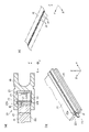
- 2(a) is a longitudinal sectional view showing the main part of the lighting device
- FIG. 2(b) is a perspective view showing the main part of the lighting device
- FIG. 2(c) is a perspective view showing the vicinity of the light source main body of the lighting device.
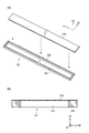
- 3(a) and 3(b) are an exploded perspective view and a longitudinal sectional view, respectively, showing Configuration Example-1 of the wavelength conversion mechanism.
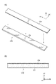
- 4(a) and 4(b) are an exploded perspective view and a vertical cross-sectional view, respectively, showing Configuration Example-2 of the wavelength conversion mechanism.
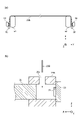
- FIG. 5(a) and 5(b) are a plan view and a longitudinal sectional view, respectively, showing a structure for supporting the wavelength conversion film in Configuration Example-3 of the wavelength conversion mechanism.
- FIG. 6 is a plan view showing a structure in which a plurality of types of wavelength conversion films are switched by a reel winding method in Configuration Example-4 of the wavelength conversion mechanism.
- FIG. 7 is a diagram showing an example of automatic switching of a plurality of types of wavelength conversion films in the configuration example of the wavelength conversion mechanism shown in FIG.
- FIG. 8 is a diagram showing an example in which two types of wavelength conversion films are overlapped and used in the configuration example-4 of the wavelength conversion mechanism shown in FIG. FIG.
- FIG. 9 is a vertical cross-sectional view showing a structure in which a plurality of types of wavelength conversion films are switched by a slide method in Configuration Example-5 of the wavelength conversion mechanism.
- FIG. 10 is a plan view showing a structure in which a plurality of types of wavelength conversion films are switched by a belt system in Configuration Example-6 of the wavelength conversion mechanism.
- FIG. 11(a) is a plan view showing the main part of the illumination device in Configuration Example-7
- FIG. 11(b) is a front view showing an example of the appearance of the wavelength conversion mechanism.
- FIG. 12 is a graph showing an example of characteristic curves of the wavelength conversion film in the embodiment.
- FIG. 13 is a longitudinal sectional view showing an outline of a plant cultivation system in another embodiment of the invention.
- FIG. 14 is a longitudinal sectional view showing an outline of a plant cultivation system in another embodiment of the invention.
- FIG. 15 is a graph showing examples of spectra before and after insertion of the wavelength conversion film.
- FIG. 1 shows the internal structure of the main part of the plant cultivation system 10 according to the embodiment of the present invention.
- the plant cultivation system 10 shown in FIG. 1 can be used, for example, by installing it indoors in a building and using it as a cultivation apparatus such as a plant factory.
- a plurality of plant cultivation systems 10 having the same structure are prepared and arranged in layers in the vertical direction, or as described later with reference to FIG.
- the cultivation room 11 is formed in a rectangular parallelepiped shape, for example, and a closed space 12 is formed inside. That is, air circulation is blocked inside and outside the cultivation room 11 so that the environment in the closed space 12 can be maintained in a state different from the outside air. Therefore, the bottom surface, side wall surfaces, ceiling surface, and the like of the cultivation chamber 11 are surrounded by a material having a certain degree of heat insulation and airtightness, and are isolated from the outside space.
- the cultivation room 11 may be an open space.
- a plant cultivation system 10A in which the cultivation room 11 is an open space will be described later with reference to FIG. 13 .
- a cultivation container 13 is installed inside the closed space 12 , and a plant 14 is cultivated in this cultivation container 13 .
- an air conditioner 15 is installed inside the enclosed space 12 to enable temperature control within the enclosed space 12 .
- a moisture permeable membrane 16 is installed at the boundary between the inside and outside of the cultivation room 11 .
- This moisture-permeable film 16 blocks air circulation, but has a dehumidifying function for expelling the moisture inside to the outside by utilizing the humidity gradient between the inside and the outside.
- a blower 17 is also installed in the closed space 12 .
- the method for dehumidifying the closed space 12 is not limited to the moisture permeable membrane 16 and the air blower 17 .
- a lighting device 20 capable of irradiating the light necessary for growing the plants 14 is arranged above the plants 14 .
- the light source main body 21 of the lighting device 20 is arranged outside the cultivation room 11 , and the wide surface of the thin light guide plate 22 optically connected to the light source main body 21 is positioned near the ceiling of the closed space 12 . are placed. That is, the light emitted from the light source main body 21 is incident on one side end 22a (edge, incident side end face) of the light guide plate 22, propagates while repeating reflection inside the light guide plate 22, and reaches the bottom of the light guide plate 22. The light is emitted downward while diffusing from the surface 22b, and the plant 14 is irradiated with the light.
- the light source body 21 is an LED (light emitting diode) device that emits white, blue, or ultraviolet light.
- a wavelength conversion mechanism 23 is installed between them. Further, as will be described later, the wavelength conversion mechanism 23 of this embodiment is configured to be easily detachable and replaceable so that spectrum adjustment can be performed as required.
- a carbon dioxide supply facility 30 is installed near the light source main body 21 .
- This carbon dioxide supply facility 30 includes an adsorbent 31 , a pipe 32 , an electromagnetic valve 33 , a pipe 34 and an electromagnetic valve 35 .
- the adsorbent 31 can adsorb only carbon dioxide (CO 2 ) from the supplied air when the temperature is low.
- the adsorbent 31 can release the adsorbed carbon dioxide when the temperature is high.
- waste heat from the light source main body 21 is used to control the adsorption/desorption operation of carbon dioxide in the adsorbent 31 .
- the solenoid valve 35 the carbon dioxide released by the adsorbent 31 can be introduced into the closed space 12 via the pipe 34 .
- the carbon dioxide supply equipment 30 supplies the amount of carbon dioxide that is consumed by photosynthesis during the growth of the plant 14, thereby maintaining the carbon dioxide concentration in the closed space 12 in a state suitable for the growth of the plant 14. be able to.
- the method of supplying carbon dioxide is not limited to the method using the carbon dioxide supply equipment 30, and for example, a cylinder storing carbon dioxide may be used.
- the carbon dioxide supply facility 30 can supply carbon dioxide extracted from the atmosphere using the adsorbent 31, so there is no need to prepare a large facility such as a cylinder.
- FIGS. 2(a) to 2(c) A configuration example of the illumination device 20 is shown in FIGS. 2(a) to 2(c).
- 2(a) and 2(b) show the main part of the lighting device 20, and
- FIG. 2(c) shows the vicinity of the light source main body 21 in the lighting device 20.
- a thin plate-like circuit board 25 is fixed substantially in the center of the opening of the heat sink 26 , and the light source main body 21 is installed on this circuit board 25 .
- the circuit board 25 is an electrically insulating substrate on which a circuit pattern is formed.
- the actual light source main body 21 is composed of a large number of LED elements arranged in a line on a circuit board 25 as shown in FIG. 2(c). Each LED element can emit blue, ultraviolet, or white light in the X-axis direction.
- the light guide plate 22 is sandwiched between heat sinks 26 at its upper and lower sides with its side end portion 22a facing the light emitting surface of the light source main body 21 with a gap therebetween. Fixed.
- the light guide plate 22 has a uniform thickness in the Z-axis direction over its entirety, and the dimension d1 in the thickness direction is, for example, several mm to 30 mm.
- a heat sink 26 supports the wavelength conversion mechanism 23, which is elongated in a ribbon shape, so as to be slidable in the Y-axis direction through guide grooves 26a and 26b. Therefore, the operator can insert the wavelength conversion mechanism 23 from the front side of the heat sink 26 along the guide grooves 26a and 26b to attach it, or remove the wavelength conversion mechanism 23 by pulling it out from the front side.
- the wavelength conversion mechanism 23 can be easily attached and detached without opening the closed space 12.
- the effective thickness dimension d2 is equivalent to the side end portion 22a of the light guide plate 22.
- the distance L1 between the side end portion 22a of the light guide plate 22 and the wavelength conversion mechanism 23 can be changed as required, as long as an appropriate air layer can be formed in this portion.
- the surface of the wavelength conversion mechanism 23, the surface of the side end portion 22a of the light guide plate 22, and the light exit surface of the light source main body 21 are arranged substantially parallel.
- a distance L2 between the wavelength conversion mechanism 23 and the light emitting surface of the light source main body 21 is appropriately determined so that the intensity of incident light in the wavelength conversion mechanism 23 does not become too large. That is, if the intensity of incident light in the wavelength conversion mechanism 23 becomes excessive, the material of the wavelength conversion mechanism 23 is likely to deteriorate. is desirable.
- FIGS. 3(a) and 3(b) Configuration Example-1 of the wavelength conversion mechanism 23 is shown in FIGS. 3(a) and 3(b).
- FIG. 3(a) shows an exploded state
- FIG. 3(b) shows a cross-sectional structure.
- the wavelength conversion mechanism 23 shown in FIGS. 3(a) and 3(b) includes a ribbon-like (elongated shape) wavelength conversion film 23a and an elongated rectangular support frame 23b in the thickness direction (A3 direction). , and attached in the vicinity of the four sides of the outline of the shape of the support frame 23b, that is, at the portion of the frame.
- the thickness of the wavelength conversion film 23a is, for example, about 100 [ ⁇ m].
- the area of the wavelength conversion film 23a is, for example, five times or less the light emitting area of the light source main body 21 .
- the support frame 23b is formed in a thin flat plate shape using a material such as resin having a certain degree of rigidity, and an opening 23c is formed except for the portion of the frame (periphery). Therefore, light can pass through the support frame 23b at the location of the opening 23c (the central portion other than the peripheral portion). Moreover, since the support frame 23b has rigidity, the wavelength conversion film 23a integrated with the support frame 23b can be supported so as to always maintain its planar shape without bending.
- the wavelength conversion mechanism 23 shown in FIGS. 3(a) and 3(b) can always maintain a planar shape, it can be used as a solid wavelength conversion device that is easy to handle.
- an operator holds one end in the longitudinal direction (A1 direction) of the wavelength conversion mechanism 23 by hand and guides it from the front side of the Y-axis shown in FIGS. It is easy to insert the wavelength conversion mechanism 23 into the grooves 26a and 26b in the longitudinal direction and pull it out toward the front.
- the intervals L1 and L2 shown in FIG. 2(a) can always be maintained in a proper state.
- the wavelength conversion mechanism 23 may be slid in the width direction (longitudinal direction) to attach and detach from the heat sink 26 .
- a slit is provided to open the bottom of the guide groove 26a in the upper wall of the heat sink 26 shown in FIGS.
- the operator grips one end of the wavelength conversion mechanism 23 in the width direction (direction A2) and pulls the guide groove from the slit located above the Z axis shown in FIGS.
- the wavelength conversion mechanism 23 is inserted downward or pulled upward along the width direction at the location 26b. Even when the wavelength conversion mechanism 23 is moved along the vertical direction in this way, the attachment/detachment work can be easily performed.
- FIGS. 4(a) and 4(b) Configuration Example-2 of the wavelength conversion mechanism 23 is shown in FIGS. 4(a) and 4(b).
- FIG. 4(a) shows an exploded state
- FIG. 4(b) shows a cross-sectional structure.
- the wavelength conversion mechanism 23A shown in FIGS. 4(a) and 4(b) has a ribbon-like elongated wavelength conversion film 23a and an elongated rectangular thin acrylic plate 23d in the thickness direction (A3 direction). are stacked on top of each other, and the stacked opposing surfaces are attached to each other to be integrated.
- the thickness of the wavelength conversion film 23a is, for example, about 100 [ ⁇ m].
- the wavelength conversion film 23a and the acrylic plate 23d do not necessarily need to be adhered together to form a single body. and may be superimposed on each other.
- the acrylic plate 23d is colorless and transparent and transmits light, the light incident on the surface can be directly guided to the opposing surface of the wavelength conversion film 23a. Moreover, since the acrylic plate 23d has a certain degree of rigidity, the wavelength conversion film 23a can be supported so as to always maintain its planar shape.
- the wavelength conversion mechanism 23A shown in FIGS. 4(a) and 4(b) can also be used as an easy-to-handle solid wavelength conversion device.
- an operator holds one end in the longitudinal direction (A1 direction) of the wavelength conversion mechanism 23A by hand and guides it from the front side of the Y-axis shown in FIGS. It is easy to insert the wavelength conversion mechanism 23A into the grooves 26a and 26b in the longitudinal direction and pull it out toward the front.
- the intervals L1 and L2 shown in FIG. 2(a) can always be maintained in a proper state.
- the wavelength conversion mechanism 23A may be slid in the width direction (longitudinal direction) to attach and detach from the heat sink 26.
- a slit is provided to open the bottom of the guide groove 26a in the upper wall of the heat sink 26 shown in FIGS.
- the operator grips one end of the wavelength conversion mechanism 23A in the width direction (direction A2) and pulls the guide groove from the slit located above the Z axis shown in FIGS.
- the wavelength conversion mechanism 23A is inserted downward or pulled upward along the width direction at the location 26b. Even when the wavelength conversion mechanism 23A is moved along the vertical direction in this way, the attachment/detachment work can be easily performed.
- FIG. 5(a) shows the structure for supporting the wavelength conversion film 23B in the configuration example-3 of the wavelength conversion mechanism 23, and FIG. 5(b) shows the cross-sectional structure.
- a single ribbon-shaped wavelength conversion film 23B is used as the wavelength conversion mechanism 23 as it is.
- the wavelength conversion film 23B has a small thickness and is easily bent as it is, it is necessary to devise ways to maintain the planar shape in order to use it as the wavelength conversion mechanism 23 .
- Projections 53 and 54 are formed on the film guide members 51 and 52, respectively.
- the elastic member may be attached to only one of the two film guide members 51 and 52.
- one end of the wavelength conversion film 23B may be fixed to the heat sink 26B via a spring or the like so that longitudinal tension is generated.
- a winding mechanism such as a tape measure, may be connected to one end of the wavelength conversion film 23B to apply tension.
- the heat sink 26B is formed with an opening 26c at the top. Accordingly, the operator holds both ends of the wavelength conversion film 23B by hand, inserts the entire wavelength conversion film 23B from above into the space inside the heat sink 26B, and arranges and fixes the wavelength conversion film 23B at a predetermined position. be able to.
- the engagement terminals 55 and 56 can be removed from the projections 53 and 54, and the wavelength conversion film 23B can be removed by lifting the wavelength conversion film 23B upward.
- this single wavelength conversion film 23B is shown in FIG. 2(a). It can be attached and detached by inserting and pulling out along the guide grooves 26a and 26b.
- FIGS. 6 to 8 show a structure in which a plurality of types of wavelength conversion films 23g1, 23g2, 23g3, and 23g4 included in the wavelength conversion mechanism 23B1 are switched by a reel winding method.
- the single ribbon-shaped wavelength conversion film 23B is used as the wavelength conversion mechanism 23 as it is.
- the wavelength conversion mechanism 23B1 shown in FIG. 6 has a plurality of types of wavelength conversion films 23g1, 23g2, 23g3, and 23g4 containing different types of phosphors, as shown in FIG.
- the wavelength conversion mechanism 23B1 includes, for example, ribbon-like wavelength conversion films 23g1, 23g2, 23g3, and 23g4 that are adjusted to absorb light from a blue LED and emit light in pink, red, orange, and yellow, respectively. They are connected to each other in the longitudinal direction (Y-axis direction) with a colorless film containing no body interposed therebetween.
- a plurality of types of wavelength conversion films 23g1, 23g2, 23g3, and 23g4 may be connected to each other without sandwiching a colorless film.
- the wavelength conversion mechanism 23B1 is used while wound on the reel 71A.
- the wavelength conversion mechanism 23B1 is inserted in the Z-axis direction into the opening 26c (see FIG. 5B) of the heat sink 26B by an operator with one end pulled out from the reel 71A.
- One end of the wavelength conversion mechanism 23B1 is wound around the reel 71B.
- the wavelength conversion mechanism 23B1 is tensioned by holding portions 73A and 73B via film guide members 72A and 72B provided in the vicinity of both ends of the heat sink 26B in the Y-axis direction, respectively, so that the plane shape is maintained without bending.
- the holding portions 73A and 73B are arranged near the film guide members 72A and 72B, respectively, and adjust the rotation direction, rotation speed, and rotation amount of the reels 71A and 71B according to instructions from a control device (not shown), for example.
- the wavelength conversion mechanism 23B1 rotates the reels 71A and 71B according to instructions from the control device, and positions the desired wavelength conversion films 23g1, 23g2, 23g3, and 23g4 between the light source body 21 and the light guide plate 22. , can be automatically switched to the desired emission color.
- two wavelength conversion mechanisms 23B1 wound around two reels 71 are prepared, and as shown in FIG. may be used.
- FIG. 8 by adding a set of film guide members 72A, 72B and holding portions 73A, 73B in FIG. can be done.
- FIG. 9 shows a structure in which a plurality of types of wavelength conversion films 23g5, 23g6, 23g7, and 23g8 included in the wavelength conversion mechanism 23B2 are switched by a sliding method.
- a wavelength conversion mechanism 23B2 shown in FIG. 9 has a plurality of types of wavelength conversion films 23g5, 23g6, 23g7, and 23g8 with mutually different colors.
- the wavelength conversion mechanism 23B2 is formed by ribbon-shaped wavelength conversion films 23g1, 23g2, 23g3, and 23g4 formed in, for example, colorless, pink, blue, and yellow, and connected to each other in the lateral direction (Z-axis direction). be.
- the wavelength conversion mechanism 23B2 is inserted into the heat sink 26C so as to be slidable in the vertical direction (Z direction).
- the heat sink 26C has openings formed in the upper and lower portions thereof, and a pair of driving rollers 75, 75 and a pair of driving rollers 76, 76 are provided in each opening.
- the wavelength conversion mechanism 23B2 is inserted into the opening of the heat sink 26C, and tension is applied by driving rollers 75, 75 and 76, 76 between the light source main body 21 and the light guide plate 22, so that the wavelength conversion mechanism 23B2 is formed into a planar shape without bending. is maintained.
- the driving rollers 75, 75 and 76, 76 are adjusted in rotation direction, rotation speed, and rotation amount, for example, according to instructions from a control device (not shown).
- drive rollers 75, 75 and 76, 76 rotate according to instructions from the control device, and desired wavelength conversion films 23g5, 23g6, 23g7, 23g8 are formed between the light source main body 21 and the light guide plate 22. By positioning the , it is possible to automatically switch to the desired emission color. Either one of the driving rollers 75, 75 may be driven while the other rotates freely, or either one of the driving rollers 76, 76 may be driven while the other rotates freely. Further, when the wavelength conversion mechanism 23B2 is formed of a material and a size that are hard to bend and easy to maintain the planar shape, one of the driving rollers 75, 75 and 76, 76 is driven, and the rest are free. May rotate.
- the wavelength conversion mechanism 23B2 shown in FIG. 9 by preparing two wavelength conversion mechanisms 23B2, two types of wavelength conversion films may be overlapped and used. Further, for example, the emission color may be adjusted by adjusting the position in the Z direction between the light source body 21 and the light guide plate 22 of the connecting portion of the two types of wavelength conversion films 23g6 and 23g7.
- FIG. 10 shows a structure in which a plurality of types of wavelength conversion films 23g10, 23g11, 23g12, 23g13, 23g14, and 23g15 included in the wavelength conversion mechanism 23B3 are switched by a belt type.
- the wavelength conversion mechanism 23B3 shown in FIG. 10 has multiple types of wavelength conversion films 23g10, 23g11, 23g12, 23g13, 23g14, and 23g15 of mutually different colors.
- the ribbon-shaped wavelength conversion films 23g10, 23g11, 23g12, 23g13, and 23g14 are adjusted so as to emit green, red, pink, blue, and yellow light, for example, in the lateral direction (Z-axis direction). are connected to each other.
- a wavelength conversion film 23g10 and a wavelength conversion film 23g14 are connected by a colorless wavelength conversion film 23g15 to form an endless belt.
- the wavelength conversion mechanism 23B3 is inserted in the Y direction through the upper and lower openings of the heat sink 26C, and tension is applied between the light source main body 21 and the light guide plate 22 by drive rollers 75, 75 and 76, 76. , the planar shape is maintained without bending. As described above, the driving rollers 75, 75 and 76, 76 are adjusted in rotation direction, rotation speed, and rotation amount according to instructions from a control device (not shown), for example.
- a film guide member may be provided at the edge of the heat sink 26C, for example.
- wavelength conversion mechanism 23B3 In the wavelength conversion mechanism 23B3, drive rollers 75, 75 and 76, 76 rotate according to instructions from the control device, and desired wavelength conversion films 23g10, 23g11, 23g12, 23g13 are formed between the light source main body 21 and the light guide plate 22. , 23g14 and 23g15 can be automatically switched to a desired emission color. Further, for example, the emission color may be adjusted by adjusting the position in the Z direction between the light source body 21 and the light guide plate 22 of the connecting portion of the two types of wavelength conversion films 23g12 and 23g13.
- FIG. 11(a) shows the main part of the illumination device 20B in configuration example-7
- FIG. 11(b) shows an example of the appearance of the wavelength conversion mechanism.
- the illumination device 20B shown in FIG. 11(a) includes a large number of optical fibers 61 as a light guiding mechanism for guiding the light from each LED element of the light source body 21 into the closed space 12. That is, the ends of the optical fibers 61 on the light incident side are individually arranged at positions facing each of the large number of LED elements of the light source main body 21 .
- a wavelength conversion mechanism 23C is arranged between each optical fiber 61 and the light source main body 21 .
- this wavelength conversion mechanism 23C is composed of an acrylic plate 23f and a large number of wavelength conversion films 23e attached on the surface thereof.
- Each wavelength conversion film 23 e is formed according to the position, shape and size of the light emitting surface of each LED element of the light source body 21 and the position, shape and size of the light incident end of each optical fiber 61 . Therefore, each wavelength conversion film 23e has a very small area. Thereby, the component cost of the wavelength conversion mechanism 23C can be effectively reduced.
- each wavelength conversion film 23e is formed in a shape close to a circle. It may be appropriately determined according to the shape and size of the light incident end. It is also possible to bundle optical fibers and apply a wavelength conversion film to guide the wavelength-converted light through the optical fibers.
- FIG. 12 shows an example of the characteristic curve of the wavelength conversion film in this embodiment.
- the horizontal axis represents the wavelength of light [nm]
- the vertical axis represents the light radiation intensity [mW/m 2 ] for each wavelength.
- each film has a thickness of 100 [ ⁇ m].
- Each of these films also has dispersed inorganic phosphors having desired emission properties to provide wavelength conversion functionality. As shown in FIG. 2(a), the wavelength conversion mechanism 23 is exposed to a high-intensity light environment in the vicinity of the light source body 21 for a long period of time. High durability against light is required. Therefore, it is desirable to use inorganic phosphors for each film rather than using less durable organic dyes.
- a wavelength conversion film that can be used for the wavelength conversion mechanism 23 can be configured by selecting any one of the above three types of films or by combining a plurality of them.
- the following seven types of wavelength conversion films (1) to (7) were constructed, and the characteristics of each of these films were measured. The results are shown in FIG. 7 as characteristic curves C1-C7. (1) yellow only (2) orange only (3) red only (4) red + yellow combination (5) yellow + red combination (6) yellow + orange combination (7) orange + yellow combination
- the seven types of wavelength conversion films (1) to (7) above have characteristic curves C1 to C7 different from each other as shown in FIG. It can absorb energy of short wavelength components and emit light of relatively long wavelengths (generally red) with different spectra.
- the wavelength conversion mechanism 23 is arranged between the light source main body 21 and the light incident end of the wavelength conversion mechanism 23. Therefore, by operating this wavelength conversion mechanism 23, the wavelength can be switched. Therefore, for example, work such as attaching and detaching the fluorescent member to and from each light source body is not required, and it becomes easy for a worker or the like who manages the cultivation apparatus to switch the configuration and characteristics of the wavelength conversion mechanism 23 . Moreover, since the light source main body 21 of the lighting device 20 is arranged outside the cultivation room 11 , it is possible to prevent the heat generation of the light source main body 21 from affecting the temperature inside the closed space 12 .
- the energy required for temperature control when operating a cultivation apparatus such as a plant factory can be greatly reduced.
- the wavelength conversion mechanism 23 it is not necessary to mount a plurality of LED chips on the light source main body 21 to provide a color-tuning function, so a relatively inexpensive LED lamp can be employed.
- the wavelength conversion mechanism 23 when the wavelength conversion mechanism 23 is arranged in a state facing the side end portion 22a of the light guide plate 22, the side end portion 22a and the light source main body 21 are separated from each other. Since the area of the portion facing is small, the area required for the wavelength conversion film 23a of the wavelength conversion mechanism 23 is extremely small, and a ribbon-like wavelength conversion film with low component cost can be adopted.
- the wavelength conversion mechanism 23 is also arranged outside the cultivation room 11, it becomes easier for the operator to attach/detach and replace the wavelength conversion mechanism 23. That is, since there is no need to open the closed space 12, the wavelength conversion mechanism 23 can be easily replaced without adversely affecting the environment within the closed space 12. Moreover, since the wavelength conversion mechanism 23 itself is small, the replacement work is easy. Therefore, it becomes easy to adjust the spectrum of the light given to the plant according to the difference in the variety of each plant and the difference in the growing season. Moreover, the heat generated in the wavelength conversion film 23a along with the wavelength conversion can be discharged to the outside as it is.
- the distribution of light emitted from the light guide plate 22 into the closed space 12 is less likely to be uneven in illuminance. That is, compared with the distribution of light emitted from the light source main body 21 composed of a large number of LED elements, the light generated by the phosphor on the wavelength conversion film has a more uniform intensity distribution.
- ⁇ Plant Cultivation System with Open Cultivation Room> 13 mainly differs from the plant cultivation system 10 shown in FIG. 1 in that the cultivation chamber 11A is an open space 12A.
- 10 A of plant cultivation systems are equipped with the cultivation shelf 40 which consists of several shelves which comprise 11 A of cultivation rooms, and one or several cultivation racks 40 are arrange
- Identical or equivalent members to those shown in FIG. 1 are denoted by identical or similar reference numerals, and overlapping descriptions are omitted.
- the cultivation shelf 40 has a plurality of vertically arranged shelf plates 41 and a plurality of support plates 42 that support the sides of each shelf plate 41 .
- a cultivation container 13 is fixed to each shelf board 41 except for the uppermost shelf, and a plant 14 is cultivated in the cultivation container 13 .
- FIG. 8 shows the cultivation shelf 40 having a three-stage configuration, the number of stages of the cultivation shelf 40 is not limited to three, and may be one, two, or four or more.
- two light guide plates 22 are arranged so as to face each other, and a lighting device 20 incorporating a wavelength conversion mechanism 23 is attached to each end of the two light guide plates 22. ing.
- the lighting device 20 is attached to the support plate 42 inside the cultivation room 11A.
- two light guide plates 22 are arranged facing each other in the same manner as in the uppermost stage, and the lighting devices 20 at the respective ends of the two light guide plates 22 are arranged outside the cultivation room 11A on the support plate 42. It is attached.
- the lighting devices 20 attached to the left and right light guide plates 22 are attached to the left and right support plates 42 outside the cultivation room 11A, respectively.
- the illumination device 20 attached to the central light guide plate 22 is arranged above the plant 14 and fixed to, for example, the lower surface of the shelf plate 41 directly above.
- the same effect as the plant cultivation system 10 can be obtained in the plant cultivation system 10A in which the cultivation chamber 11A has the open space 12A. Since the wavelength conversion mechanism 23 is arranged between the light source main body 21 and the light incident end of the wavelength conversion mechanism 23, the wavelength can be switched by operating the wavelength conversion mechanism 23. FIG. Therefore, it becomes easy for an operator or the like who manages the cultivation apparatus to switch the configuration and characteristics of the wavelength conversion mechanism 23 .
- FIG. 13 shows an example in which the arrangement of the light guide plate 22 and the lighting device 20 is different for each of the upper, middle, and lower cultivation chambers 11A of the cultivation shelf 40, but the arrangement of the light guide plate 22 and the lighting device 20 is It is not limited to the illustrated one.
- the arrangement of the light guide plate 22 and the lighting device 20 is appropriately determined according to the number of plants 14 arranged in the cultivation container 13, workability, and the like.
- FIG. 13 shows an example in which two or three light guide plates 22 are continuously arranged in the left-right direction
- the number of light guide plates 22 is not limited to these, and the size of the cultivation room 11A, etc. determined as appropriate.
- the plant cultivation system 10A shown in FIG. 13 shows an example in which the cultivation rack 40 is arranged inside the building 1, the cultivation rack 40 is not necessarily installed inside the building 1 where air circulation is blocked inside and outside. It does not have to be placed.
- the cultivation shelf 40 may be arranged inside a greenhouse or the like, or may be arranged outdoors.
- a plant cultivation system 10B shown in FIG. 14 includes four cultivation chambers 11B, air conditioning units 48, and air conditioning pipes 49.
- Each cultivation room 11B has a configuration similar to that of the cultivation room 11 shown in FIG.
- Each cultivation room 11B is connected to each other by an air conditioning pipe 49 and to an air conditioning unit 48 .
- the air conditioning unit 48 has an air conditioner 15B for temperature and humidity control, a moisture permeable membrane 16B, and an air blower 17B for circulating temperature and humidity controlled air.
- the air conditioning unit 48 is closed with no exchange of air with the outside air.
- each cultivation room 11B The temperature and humidity of each cultivation room 11B are controlled by circulating the air whose temperature and humidity are controlled by the air conditioning unit 48 in the air conditioning pipe 49 and in the closed space 12 inside each cultivation room 11B using the blower 17B. .
- the air-conditioning unit 48, the air-conditioning pipe 49, and each cultivation room 11B are connected to each other to form a closed system, and there is no exchange of air with the outside.
- the air conditioning unit 48 and the air conditioning piping 49 are also made of heat insulating material and isolated from the outside space. With this configuration, a plurality of cultivation chambers 11B can be air-conditioned with a single air conditioner and moisture-permeable membrane. It is possible to increase the cultivation amount while easily maintaining the air environment by avoiding rising.
- FIG. 9 shows an example in which four cultivation chambers 11B are connected in the Y direction.
- the performance of the air conditioner, the dehumidifying membrane, and the blower can be appropriately selected according to the capacity required for air conditioning.
- This solution was applied on a PET film having a thickness of 188 ⁇ m with an applicator and air-dried to prepare a wavelength conversion film having a PVB resin layer with a red phosphor dispersed therein and a thickness of about 100 ⁇ m.
- This wavelength conversion film was cut into a piece having a width of 9 mm and a length of 40 cm to obtain a ribbon-like wavelength conversion film.
- a blue LED bar was prepared by mounting 88 surface-mounted blue LEDs (product number “67-21S/NB3C-D4555B4L12835Z15/2T” manufactured by Cree) on a mounting substrate having a width of 9 mm and a length of 288 mm.
- This blue LED bar was attached to an aluminum frame (manufactured by MISUMI Co., Ltd., 20 mm square, single groove, groove width 6 mm) as a heat sink with a heat-conducting double-sided tape to obtain an LED light source.
- the light guide plate is used by inserting the light entrance part (width 300 mm, thickness 8 mm) of a light guide plate (manufactured by Delplus Co., Ltd.) of size 300 ⁇ 600 ⁇ 8 mm into the groove (opening 8 mm) of the aluminum frame. An LED light source unit was obtained.
- a characteristic curve Cb indicates the spectrum of blue light from the LED (before the wavelength conversion film is inserted), and a characteristic curve Cr indicates the spectrum after the wavelength conversion film is inserted. As described above, it was confirmed that the blue light emitted from the LED can be easily converted into the red light suitable for plant growth by using a very simple and small-area wavelength conversion film.
- a plant cultivation system including a cultivation unit body (cultivation chamber 11) defining a cultivation space (closed space 12) for cultivating plants, and a lighting device (20) having a light source body (21) ) and a light guide mechanism (light guide plate 22 or optical fiber 61) that is connected to the lighting device and guides the light emitted from the light source main body into the cultivation space; a wavelength conversion mechanism (23, 23B1, 23B2, 23B3) arranged between the light source main body and the light incident end of the light guide mechanism for absorbing incident light and emitting wavelength-converted light;
- a plant cultivation system comprising:
- the light guide mechanism has a light guide plate (22) arranged such that at least a main portion of the light exit surface faces the cultivation space,
- the wavelength conversion mechanism is arranged at a position adjacent to the incident side end face (22a) of the light guide plate,
- the plant cultivation system according to [1] above.
- the wavelength conversion mechanism (23) includes wavelength conversion films (23a, 23e) having a planar shape formed in accordance with the shape and size of the light incident end of the light guide mechanism, The plant cultivation system according to the above [1] or [2].
- the wavelength conversion mechanism (23) includes a film support mechanism (guide grooves 26a and 26b, a support frame) that detachably supports the wavelength conversion film at a predetermined position adjacent to the light incident end of the light guide mechanism. 23b, or acrylic plates 23d, 23f), The plant cultivation system according to [3] above.
- a wavelength conversion device constructed by overlapping a translucent flat plate (acrylic plate 23d) having the same shape and size as the wavelength conversion film and the wavelength conversion film.
- the film support mechanism has grooves (guide grooves 26a and 26b) that can be engaged with at least one of both side edges in the width direction of the wavelength conversion device, and the width direction and the width direction of the wavelength conversion device.
- a guide member heat sink 26 that allows at least one of movement along the intersecting longitudinal direction and movement along the width direction, The plant cultivation system according to [4] above.
- the film support mechanism has grooves (guide grooves 26a, 26b) that can be engaged with at least one of both side edges in the width direction of the rectangular frame of the wavelength conversion device, and the wavelength conversion device,
- a guide member (heat sink 26) that allows at least one of movement along the longitudinal direction intersecting the width direction and movement along the width direction,
- the film supporting mechanism includes engaging members (engaging terminals 55, 56), and tension imparting members (film guide members 51 and 52) that apply tension in the longitudinal direction to the other end of the wavelength conversion film in the longitudinal direction.
- engaging members engaging terminals 55, 56
- tension imparting members film guide members 51 and 52
- the light guide mechanism includes one or more optical fibers (61) having one end arranged inside the cultivation space and the other end arranged outside the cultivation space,
- the wavelength conversion mechanism (23C) has a wavelength conversion film (23e) arranged adjacent to the incident side end face of the optical fiber and having a planar shape equivalent to the shape and size of the incident side end face of the optical fiber.
- the wavelength conversion mechanism includes a wavelength conversion film containing an inorganic phosphor.
- the plant cultivation system according to any one of [1] to [8] above.
- the wavelength conversion mechanism (23B1, 23B2, 23B3) includes a plurality of types of wavelength conversion films connected to each other.
- the plant cultivation system according to any one of [1] to [9] above.
- a film switching mechanism (film guide members 72A, 72B, holding portions 73A, 73B, drive rollers 75, 75 and 76, 76) that switchably holds the plurality of types of wavelength conversion films,
- the plant cultivation system according to [10] above.
- the cultivation unit main body (the plurality of cultivation chambers 11B, the air conditioning units 48, the air conditioning pipes 49) includes a plurality of the cultivation spaces (closed spaces 12) and an air conditioning unit (48), the air conditioning unit controls at least one of temperature and humidity in the plurality of cultivation spaces;
- the plant cultivation system according to any one of [1] to [11] above.
- Japanese Patent Application Laid-Open No. 2011-200204 discloses a plant-growing lighting device that uses a human sensor to switch to red lighting during plant cultivation and white lighting during work.
- this plant-growing lighting device requires a red light-emitting diode, and a control unit for switching between the white light-emitting diode and the red light-emitting diode, which increases the cost. Become.
- the plant cultivation systems 10 and 10A have a wavelength conversion mechanism, the light is converted into white light when observing the growth state of the plant with a camera or visually, and is converted into red light during cultivation. It can be suitably used for the purpose.
- the indoor illumination light can be easily converted into a desired color.
- the plant cultivation system of the present invention can be used, for example, to cultivate plants in an artificially adjusted closed space.
- Reference Signs List 10 10A, 10B Plant cultivation system 11, 11B Cultivation chamber 12 Closed space 13 Cultivation container 14 Plant 15, 15B Air conditioner 16, 16B Moisture permeable membrane 17, 17B Blower 20
- Lighting device 21 Light source body 22
Landscapes
- Life Sciences & Earth Sciences (AREA)
- Environmental Sciences (AREA)
- Biodiversity & Conservation Biology (AREA)
- Botany (AREA)
- Ecology (AREA)
- Forests & Forestry (AREA)
- Cultivation Of Plants (AREA)
Abstract
植物栽培システム(10)は、植物を栽培するための栽培空間(12)を画成する栽培ユニット本体(11)と、光源本体(21)を有する照明装置(20)とを含む。光源本体の光を、導光機構(導光板22)を用いて栽培空間(12)の内部に導く。光源本体と導光機構の光入射端との間の空間に波長変換機構(23)を配置して植物に照射する光のスペクトルを調整する。
Description
本発明は、植物栽培システムに関する。
近年、完全人工光型の植物工場が注目されている。植物工場等の栽培装置において、植物の育成に必要な光、温度、水分、二酸化炭素などの環境条件を人工的に操作することにより、狭い空間であっても効率よく植物を育成することが容易になる。完全人工光型の植物工場では、光源として、発光効率やコストの観点からLED(発光ダイオード)デバイスが多用される傾向がある。光を活用して植物の生育を促進するための技術として、特許文献1~3に記載されたものがある。
植物を栽培する際に利用する光については、植物育成の促進に適した波長が存在することが知られている。植物育成の促進に適した波長に着目した植物工場専用のLEDデバイス、すなわち、植物に存在する葉緑素(クロロフィル)が光合成に必要な光を効率よく吸収できるように設計された、照明用のLEDデバイスが販売されている。このような専用のLEDデバイスは、一般的なLEDデバイスに比べて、発光光に含まれる赤色の波長成分の割合を増やすように事前に発光スペクトルを最適化してある。
しかしながら、植物工場専用の照明用LEDデバイスは発光スペクトルの調整ができないので、植物の種類の違いや育成状況などに応じて発光スペクトルの変更が必要になった場合には、LEDデバイス自体の交換によりその種類を変えなければならなかった。しかも、このような専用のLEDデバイスは、一般的なLEDデバイスと比較して非常に高価である。また、1台のLEDデバイスに発光スペクトルの異なる複数のLEDチップを実装し、それぞれの駆動条件を制御することで、ある程度の範囲で発光スペクトルを調整できる調色型のLEDデバイスも販売されている。しかしながら、このようなLEDデバイスはさらに高価であり、一般的な植物工場にはあまり採用されていない。
これに対し、光の波長変換機能を有するフィルムが提案されている。したがって、一般照明用の安価なLEDデバイスと、波長変換フィルムとを組み合わせることで、植物の育成に適した発光スペクトルを有する光源を比較的安価に実現することが可能である。しかし、例えばLEDデバイスの外周面に沿って波長変換フィルムを巻き付けるように貼り付ける場合には、その作業に非常に手間がかかる。さらに、植物工場で栽培する植物の育成状況に合わせて、あるいは栽培する植物の種類の違いに合わせて照明光の発光スペクトルを変更したい場合がある。しかし、波長変換フィルムを巻きつけたLEDデバイスの発光スペクトルを調整するためには、植物工場の稼働中に波長変換フィルムの貼り付け及び取り外しの作業を何回も繰り返すことが予想される。
特許文献3には、青色蛍光体と赤色蛍光体を含有する透光性基材材料により成形された蛍光部材で脱着可能に覆われた植物栽培用発光ダイオードを開示する。この発光ダイオードによれば、光源全体を交換することなく所望する光のピーク波長に変更可能であるが、蛍光部材が、発光ダイオードの砲弾型部分にかぶさるキャップ形状であり、波長変換の際には、個々の発光ダイオードへの着脱が必要となる。よって、この発光ダイオードを用いても、上記波長変換フィルムと同様に、その作業に非常に手間がかかる。
特許文献1に示された例では、太陽光が照射された蛍光放射性ネットが赤色の蛍光を放射する。つまり、蛍光放射性の材料が太陽光のエネルギーを吸収して入射光とは色の異なる蛍光光を発することにより、光の波長を変換する。しかし、特許文献1においては、光の波長を変換するために、蛍光放射性ネットを農地に敷いたり、農作物を覆ったりする作業が必要となり、手間がかかる。
特許文献2は、植物を植える植物支持体を載置する植物栽培台に、光の反射率が高い素材を用いることにより、植物にあたる光の量を増やして植物の生育を促進する植物栽培ユニットを開示するが、植物の育成に適した発光スペクトルの利用については開示がない。
本発明は、上記の状況に鑑みてなされたものであり、その目的は、植物の育成に適した発光スペクトルの光源を利用することに伴う作業を容易に行える植物栽培システムを提供することである。
前述した目的を達成するために、本発明に係る植物栽培システムは、下記(1)~(12)を特徴としている。
(1) 植物を栽培するための栽培空間を画成する栽培ユニット本体と、光源本体を有する照明装置とを含む植物栽培システムであって、
前記照明装置に接続され、前記光源本体から出射される光を前記栽培空間内に導く導光機構と、
前記光源本体と前記導光機構の光入射端との間に配置され、入射光を吸収して波長変換された光を出射する波長変換機構と、
を備える植物栽培システム。
(1) 植物を栽培するための栽培空間を画成する栽培ユニット本体と、光源本体を有する照明装置とを含む植物栽培システムであって、
前記照明装置に接続され、前記光源本体から出射される光を前記栽培空間内に導く導光機構と、
前記光源本体と前記導光機構の光入射端との間に配置され、入射光を吸収して波長変換された光を出射する波長変換機構と、
を備える植物栽培システム。
(2) 前記導光機構は、光出射面の少なくとも主要部位が前記栽培空間内に対向する状態で配置された導光板を有し、
前記波長変換機構は前記導光板の入射側端面に隣接する位置に配置される、
上記(1)に記載の植物栽培システム。
前記波長変換機構は前記導光板の入射側端面に隣接する位置に配置される、
上記(1)に記載の植物栽培システム。
(3) 前記波長変換機構は、前記導光機構の光入射端の形状及び大きさに合わせて形成された平面形状を有する波長変換フィルムを含む、
上記(1)又は(2)に記載の植物栽培システム。
上記(1)又は(2)に記載の植物栽培システム。
(4) 前記波長変換機構は、前記波長変換フィルムを前記導光機構の光入射端と隣接する所定位置に対して着脱自在に支持するフィルム支持機構を含む、
上記(3)に記載の植物栽培システム。
上記(3)に記載の植物栽培システム。
(5) 前記波長変換フィルムと同等の形状及び大きさを有する透光性の平板と、前記波長変換フィルムとを面で重ね合わせて構成した波長変換デバイスを備え、
前記フィルム支持機構は、前記波長変換デバイスの幅方向の両側端部のうち少なくともいずれか一方と係合可能な溝部を有し、前記波長変換デバイスの、前記幅方向と交わる長手方向に沿った移動及び前記幅方向に沿った移動の少なくともいずれか一方を許容する案内部材を備える、
上記(4)に記載の植物栽培システム。
前記フィルム支持機構は、前記波長変換デバイスの幅方向の両側端部のうち少なくともいずれか一方と係合可能な溝部を有し、前記波長変換デバイスの、前記幅方向と交わる長手方向に沿った移動及び前記幅方向に沿った移動の少なくともいずれか一方を許容する案内部材を備える、
上記(4)に記載の植物栽培システム。
(6) 前記波長変換フィルムと同等の形状及び大きさを有しその周縁部以外の部位が開口した形状の矩形枠と前記波長変換フィルムとを重ねて、前記波長変換フィルムの周縁部を前記矩形枠に固定して構成した波長変換デバイスを備え、
前記フィルム支持機構は、前記波長変換デバイスにおける前記矩形枠の幅方向の両側端部のうち少なくともいずれか一方と係合可能な溝部を有し、前記波長変換デバイスの、前記幅方向と交わる長手方向に沿った移動及び前記幅方向に沿った移動の少なくともいずれか一方を許容する案内部材を備える、
上記(4)に記載の植物栽培システム。
前記フィルム支持機構は、前記波長変換デバイスにおける前記矩形枠の幅方向の両側端部のうち少なくともいずれか一方と係合可能な溝部を有し、前記波長変換デバイスの、前記幅方向と交わる長手方向に沿った移動及び前記幅方向に沿った移動の少なくともいずれか一方を許容する案内部材を備える、
上記(4)に記載の植物栽培システム。
(7) 前記フィルム支持機構は、リボン状に形成される前記波長変換フィルムの長手方向の一方の端部を所定部位に係合して固定可能な係合部材と、前記波長変換フィルムの長手方向の他方の端部に対して長手方向の張力を与える張力付与部材とを備える、
上記(4)に記載の植物栽培システム。
上記(4)に記載の植物栽培システム。
(8) 前記導光機構は、一端側が前記栽培空間内に配置され他端側が前記栽培空間の外側に配置された1つ以上の光ファイバを含み、
前記波長変換機構は、前記光ファイバの入射側端面に隣接する位置に配置され、前記光ファイバの入射側端面の形状及び大きさと同等の平面形状を有する波長変換フィルムを有する、
上記(1)に記載の植物栽培システム。
前記波長変換機構は、前記光ファイバの入射側端面に隣接する位置に配置され、前記光ファイバの入射側端面の形状及び大きさと同等の平面形状を有する波長変換フィルムを有する、
上記(1)に記載の植物栽培システム。
(9) 前記波長変換機構は、無機蛍光体を含む波長変換フィルムを備える、
上記(1)乃至(8)のいずれか一に記載の植物栽培システム。
上記(1)乃至(8)のいずれか一に記載の植物栽培システム。
(10) 前記波長変換機構は、互いに接続された複数種類の波長変換フィルムを備える、
上記(1)乃至(9)のいずれか一に記載の植物栽培システム。
上記(1)乃至(9)のいずれか一に記載の植物栽培システム。
(11) 前記複数種類の波長変換フィルムを切替可能に保持するフィルム切替機構を備える、
上記(10)に記載の植物栽培システム。
上記(10)に記載の植物栽培システム。
(12) 前記栽培ユニット本体は、複数の前記栽培空間と、空調ユニットと、を備え、
前記空調ユニットが、前記複数の栽培空間内の温度及び湿度の少なくともいずれか一方を制御する、
上記(1)乃至(11)のいずれか一に記載の植物栽培システム。
前記空調ユニットが、前記複数の栽培空間内の温度及び湿度の少なくともいずれか一方を制御する、
上記(1)乃至(11)のいずれか一に記載の植物栽培システム。
上記(1)の構成の植物栽培システムによれば、植物の育成に適した発光スペクトルの光を得るために利用される波長変換機構が光源本体と導光機構の光入射端との間に配置されているので、この波長変換機構を操作することにより波長を切り替えられる。よって、例えば蛍光部材を個々の光源本体に着脱するような作業が不要となり、栽培装置を管理する作業者等が波長変換機構の構成や特性を切り替えるように操作することが容易となる。更に、波長変換機構が光源本体と導光機構の光入射端との間に配置されていることから、波長変換機構に必要とされる光路の断面積が小さくなり、波長変換フィルム等の面積も小さくなる。したがって、波長変換機構の部品コストを低減できる。
上記(2)の構成の植物栽培システムによれば、導光板の光出射面の面積を大きくすることで、栽培空間内の広い範囲に亘り、植物の育成に必要な十分な光量の光を照射することが可能になる。しかも、波長変換機構が導光板の入射側端面に隣接する位置に配置されているので、波長変換機構に必要とされる光路の断面積が小さくなり、波長変換フィルム等の面積が小さくなる。したがって、波長変換機構の部品コストを低減できる。
上記(3)の構成の植物栽培システムによれば、波長変換フィルムを必要に応じて着脱することが容易であり、波長変換フィルムの種類を切り替えることにより、植物の種類の違いや育成状況の変化に合わせて発光スペクトルを変更する操作が容易になる。
上記(4)の構成の植物栽培システムによれば、波長変換フィルムは導光機構の光入射端の形状及び大きさに合わせて形成された平面形状を有するので必要な面積が小さくなり、部品コストを低減でき、交換の作業も容易になる。
上記(5)の構成の植物栽培システムによれば、波長変換デバイスの着脱を容易に行うことができる。また、それぞれ特性が異なる複数種類の波長変換デバイスを予め用意しておけば、それらを作業者が着脱し交換するだけの簡単な操作により、発光スペクトルの変更ができる。
上記(6)の構成の植物栽培システムによれば、波長変換デバイスの着脱を容易に行うことができる。また、それぞれ特性が異なる複数種類の波長変換デバイスを予め用意しておけば、それらを作業者が着脱し交換するだけの簡単な操作により、発光スペクトルの変更ができる。
上記(7)の構成の植物栽培システムによれば、前記波長変換フィルムを所定の部位に配置して所定の平面形状を維持した状態で固定したり、取り外して交換することが容易になる。したがって、それぞれ特性が異なる複数種類の前記波長変換フィルムを予め用意しておけば、それらを作業者が着脱し交換するだけの簡単な操作により、発光スペクトルの変更ができる。
上記(8)の構成の植物栽培システムによれば、前記光ファイバの一端側を前記栽培空間内の所定位置に配置することで、前記栽培空間内の植物が存在する箇所に集中的に十分な明るさの光を照射することが容易になる。また、前記波長変換フィルムは前記光ファイバの入射側端面の形状及び大きさと同等の平面形状であるため、その面積が小さくなり部品コストの低減が可能になる。また、前記波長変換フィルムの面積が小さいので、その着脱操作が容易になる。
上記(9)の構成の植物栽培システムによれば、前記波長変換フィルムが無機蛍光体により波長変換を行うので、有機色素を利用する場合と比べると照射光に対する耐久性が大幅に改善される。したがって、前記波長変換フィルムを前記光源本体の近傍に配置した場合でも長期間に亘って特性の劣化が生じにくい。
上記(10)の構成の植物栽培システムによれば、波長変換機構が、互いに接続された複数種類の波長変換フィルムを備えるので、光源本体と導光機構の光入射端との間に配置する波長変換フィルムの種類を変更することで、所望の発光色に切り替えられる。
上記(11)の構成の植物栽培システムによれば、複数種類の波長変換フィルムを切替可能に保持するフィルム切替機構を備えるので、複数種類の波長変換フィルムを自動で切り替えて、所望の発光色に自動で切り替えられる。
上記(12)の構成の植物栽培システムによれば、前記空調ユニットと前記複数の栽培空間とが連結して閉鎖系を構成し、外部との空気のやり取りを行うことがないので、栽培空間内の空気環境を容易に維持しつつ、栽培量を増やすことができる。
本発明の植物栽培システムによれば、植物の育成に適した発光スペクトルの光源を利用することに伴う作業を容易化できる。
以上、本発明について簡潔に説明した。更に、以下に説明される発明を実施するための最良の形態を添付の図面を参照して通読することにより、本発明の詳細は更に明確化されるであろう。
本発明に関する具体的な実施の形態について、各図を参照しながら以下に説明する。
<植物栽培システムの構成>
本発明の実施形態における植物栽培システム10の主要部の内部構造を図1に示す。
<植物栽培システムの構成>
本発明の実施形態における植物栽培システム10の主要部の内部構造を図1に示す。
図1に示した植物栽培システム10は、例えば建物の屋内に設置して植物工場等の栽培装置として使用するために利用できる。また、植物栽培システム10が比較的小型の場合には、同じ構造の複数の植物栽培システム10を用意して、これらを縦方向に積層して配置したり、図14を参照して後述するように、横方向に複数並べて配置して同時に使用することも想定できる。
図1の植物栽培システム10においては、栽培室11が例えば直方体形状に形成され、その内部に閉鎖空間12が形成されている。すなわち、閉鎖空間12内の環境を外気とは異なる状態に維持できるように、栽培室11の内外で空気の流通が阻止される。したがって、栽培室11の底面、各側壁面、天井面などがある程度の断熱性及び気密性を有する材料で囲まれて外部の空間と隔離されている。植物栽培システム10においては、栽培室11が閉鎖空間12である例を示すが、栽培室11は開放された空間であってもよい。栽培室11が開放された空間である植物栽培システム10Aについては、図13を参照して後述する。
閉鎖空間12の内部に栽培容器13が設置されており、この栽培容器13の中で植物14が栽培される。図1の例では、閉鎖空間12内の温度調節を可能にするために、エアコン15が閉鎖空間12の内部に設置されている。また、栽培室11の内外の境界箇所に透湿膜16が設置してある。この透湿膜16は、空気の流通は阻止するが、内外の湿度勾配を利用して内側の水分を外側に排出するための除湿機能を備えている。また、送風機17が閉鎖空間12内に設置されている。尚、閉鎖空間12内の除湿を行う方式は、透湿膜16及び送風機17に限定されない。
一方、植物14の育成に必要な光を照射可能な照明装置20が植物14の上方に配置されている。実際には、照明装置20の光源本体21は栽培室11の外側に配置されており、光学的に光源本体21と接続された薄板状の導光板22の広い面が閉鎖空間12の天井付近に配置されている。つまり、光源本体21の発光光は、導光板22の一方の側端部22a(エッジ、入射側側端面)に入射し、導光板22の内部で反射を繰り返しながら伝搬し、導光板22の下方の面22bから拡散しながら下方に向けて出射され、植物14に照射される。
また、光源本体21は白色又は青色、もしくは紫外で発光するLED(発光ダイオード)デバイスであり、植物14に照射する光の波長のスペクトル調整を可能にするために、光源本体21と導光板22との間に波長変換機構23が設置してある。また、後述するように本実施形態の波長変換機構23は、必要に応じてスペクトル調整ができるように着脱や交換が容易にできるように構成してある。
また、光源本体21の近傍に二酸化炭素供給設備30が設置してある。この二酸化炭素供給設備30は、吸着剤31、配管32、電磁弁33、配管34、及び電磁弁35を含んでいる。電磁弁33を開くことにより、配管32を介して大気を吸着剤31の箇所に供給することができる。吸着剤31は、供給された大気中から二酸化炭素(CO2)だけを温度が低いときに吸着することができる。また、吸着剤31は吸着した二酸化炭素を温度が高いときに放出することができる。本実施形態では、吸着剤31における二酸化炭素の吸着/放出の動作を制御するために、光源本体21からの廃熱を利用している。電磁弁35を開くことにより、吸着剤31が放出した二酸化炭素を配管34を経由して閉鎖空間12の内部に導入することができる。
すなわち、植物14の育成時に光合成に伴って消費される分の二酸化炭素を二酸化炭素供給設備30から供給することで、閉鎖空間12内の二酸化炭素濃度を植物14の育成に適した状態に維持することができる。二酸化炭素の供給方式は、二酸化炭素供給設備30による方式に限定されず、例えば、二酸化炭素を蓄積したボンベを用いてもよい。本実施形態では、二酸化炭素供給設備30によって、吸着剤31を利用して大気中から取り出した二酸化炭素を供給できるので、ボンベのような大型の設備を特別に用意する必要がない。
<照明装置の構成>
照明装置20の構成例を図2(a)~図2(c)に示す。図2(a)及び図2(b)は照明装置20の主要部を表し、図2(c)は照明装置20における光源本体21の近傍を表している。
照明装置20の構成例を図2(a)~図2(c)に示す。図2(a)及び図2(b)は照明装置20の主要部を表し、図2(c)は照明装置20における光源本体21の近傍を表している。
図2(a)に示した例では、ヒートシンク26の開口した箇所の略中央に薄板状の回路基板25が固定してあり、この回路基板25上に光源本体21が設置されている。回路基板25は、電気絶縁性の基板上に回路パターンが形成されたものである。実際の光源本体21は、図2(c)に示すように回路基板25上に一列に並べて配置された多数のLED素子で構成されている。各LED素子は、青色、紫外又は白色の光をX軸方向に向けて出射するように発光できる。
図2(a)、図2(b)に示すように、導光板22はその側端部22aが間隔を空けて光源本体21の光出射面と対向する状態で、上下をヒートシンク26で挟まれ固定されている。導光板22は全体に亘ってZ軸方向の厚みが均一であり、厚み方向寸法d1は例えば数mm~30mm程度である。
ヒートシンク26上には、導光板22の側端部22aと光源本体21との間の上下に、波長変換機構23を装着するために必要な案内溝26a、26bが形成してある。すなわち、この例ではリボン状に細長く形成された波長変換機構23をヒートシンク26が案内溝26a、26bでY軸方向にスライド可能な状態で支持している。したがって、作業者は波長変換機構23をヒートシンク26の手前側から案内溝26a、26bに沿って差し込んで装着したり、手前側に波長変換機構23を引き抜いて取り外すことができる。特に、導光板22の側端部22aは栽培室11の外側の空間に存在しているので、閉鎖空間12を開放することなく波長変換機構23を容易に着脱できる。
波長変換機構23におけるZ軸方向の幅は案内溝26a、26bの分だけ導光板22よりも大きいが、有効な厚み方向寸法d2は、導光板22の側端部22aと同等である。導光板22の側端部22aと波長変換機構23との間の間隔L1は、この部分に適当な空気層が形成できる状態であればよいので、必要に応じて変更できる。波長変換機構23の面、導光板22の側端部22aの面、及び光源本体21の光出射面は略平行に配置してある。波長変換機構23と、光源本体21の光出射面との間の間隔L2は、波長変換機構23における入射光強度が大きくなりすぎないように適宜決定される。すなわち、波長変換機構23における入射光強度が過大になると、波長変換機構23の材料が劣化しやすくなるので、適度な間隔L2を形成して光源本体21の光出射面からある程度の距離を離すことが望ましい。
<波長変換機構の構成例-1>
波長変換機構23の構成例-1を図3(a)、及び図3(b)に示す。図3(a)は分解した状態を示し、図3(b)は断面構造を示している。
波長変換機構23の構成例-1を図3(a)、及び図3(b)に示す。図3(a)は分解した状態を示し、図3(b)は断面構造を示している。
図3(a)及び図3(b)に示した波長変換機構23は、リボン状(細長い形状)の波長変換フィルム23aと、細長い矩形形状の支持枠23bとをそれらの厚み方向(A3方向)に重ねて、支持枠23bの形状における輪郭の4つの辺の近傍、すなわち枠の箇所で貼り付けて一体化してある。波長変換フィルム23aの厚みは、例えば100[μm]程度である。波長変換フィルム23aの面積は、一例として、光源本体21の発光面積の5倍以下である。
支持枠23bは、ある程度の剛性を有する樹脂などの材料を用いて薄い平板形状に構成してあり、枠の箇所(周縁部)を除いて開口部23cが形成されている。したがって、開口部23cの箇所(周縁部以外の部位である中央部)では光が支持枠23bを通過することができる。また、支持枠23bが剛性を有しているので、支持枠23bと一体化された波長変換フィルム23aが撓むこと無く常時平面形状を維持するように支持することができる。
つまり、図3(a)及び図3(b)に示した波長変換機構23は常時平面形状を維持できるので、取り扱いが容易な固体の波長変換デバイスとして利用することができる。一例として、作業者が波長変換機構23の長手方向(A1方向)の一方の端部を手で把持すると共に、図2(a)、図2(b)に示したY軸の手前側から案内溝26a、26bの箇所に波長変換機構23を長手方向に向かって差し込んだり、手前側に引き抜いたりする作業が容易である。また、図2(a)に示した間隔L1、L2を適正な状態に常時維持できる。
また、他の例として、波長変換機構23を幅方向(縦方向)にスライドさせてヒートシンク26に脱着してもよい。この場合、図2(a)、図2(b)に示すヒートシンク26の上壁における案内溝26aの底部をヒートシンク26の上面に開放させたスリットを設けておく。作業者は、波長変換機構23の幅方向(A2方向)の一方の端部を把持すると共に、図2(a)、図2(b)に示したZ軸の上側に位置するスリットから案内溝26bの箇所に波長変換機構23を幅方向に沿って、下側に向かって差し込んだり、上側に引き抜いたりする。このように波長変換機構23を縦方向に沿って移動する場合にも、脱着作業を容易に行うことができる。
<波長変換機構の構成例-2>
波長変換機構23の構成例-2を図4(a)、及び図4(b)に示す。図4(a)は分解した状態を示し、図4(b)は断面構造を示している。
波長変換機構23の構成例-2を図4(a)、及び図4(b)に示す。図4(a)は分解した状態を示し、図4(b)は断面構造を示している。
図4(a)及び図4(b)に示した波長変換機構23Aは、リボン状の細長い形状の波長変換フィルム23aと、細長い矩形形状の薄いアクリル板23dとをそれらの厚み方向(A3方向)に重ね、重ねた対向面同士を貼り付けて一体化してある。波長変換フィルム23aの厚みは、例えば100[μm]程度である。波長変換フィルム23aとアクリル板23dは必ずしも貼り付けて一体化されている必要はなく、界面に空気層が介在するように端部のみをテープで固定した状態で、波長変換フィルム23aとアクリル板23dとを面で重ね合わせて構成しても良い。
アクリル板23dは無色透明であり、光を透過するので、表面に入射した光をそのまま対向する波長変換フィルム23aの面に導くことができる。また、アクリル板23dがある程度の剛性を有しているので、波長変換フィルム23aが平面形状を常時維持するように支持することができる。
したがって、図4(a)及び図4(b)に示した波長変換機構23Aについても、取り扱いが容易な固体の波長変換デバイスとして利用することができる。一例として、作業者が波長変換機構23Aの長手方向(A1方向)の一方の端部を手で把持すると共に、図2(a)、図2(b)に示したY軸の手前側から案内溝26a、26bの箇所に波長変換機構23Aを長手方向に向かって差し込んだり、手前側に引き抜いたりする作業が容易である。また、図2(a)に示した間隔L1、L2を適正な状態に常時維持できる。
また、他の例として、波長変換機構23Aを幅方向(縦方向)にスライドさせてヒートシンク26に脱着してもよい。この場合、図2(a)、図2(b)に示すヒートシンク26の上壁における案内溝26aの底部をヒートシンク26の上面に開放させたスリットを設けておく。作業者は、波長変換機構23Aの幅方向(A2方向)の一方の端部を把持すると共に、図2(a)、図2(b)に示したZ軸の上側に位置するスリットから案内溝26bの箇所に波長変換機構23Aを幅方向に沿って、下側に向かって差し込んだり、上側に引き抜いたりする。このように波長変換機構23Aを縦方向に沿って移動する場合にも、脱着作業を容易に行うことができる。
<波長変換機構の構成例-3>
波長変換機構23の構成例-3において波長変換フィルム23Bを支持する構造を図5(a)に示し、断面構造を図5(b)に示す。
波長変換機構23の構成例-3において波長変換フィルム23Bを支持する構造を図5(a)に示し、断面構造を図5(b)に示す。
図5(a)、図5(b)に示した例では、単体のリボン形状の波長変換フィルム23Bをそのまま波長変換機構23として使用している。但し、波長変換フィルム23Bは厚みが小さくそのままでは撓みやすいので、波長変換機構23として使用するためには平面形状を維持するための工夫が必要になる。
そこで、波長変換フィルム23Bの長手方向(Y軸方向)の両端の間に張力をかけて撓みを生じさせずに装着できるように構成してある。すなわち、図5(a)の例では、ヒートシンク26B(図5(b)参照)のY軸方向の両端近傍に弾性を有するフィルムガイド部材51、52を配置して、Y軸方向に張力が発生するように構成してある。
各フィルムガイド部材51、及び52には、それぞれ突起部53、及び54が形成してある。波長変換フィルム23Bの一端側に取り付けた係合端子55が突起部53と係合し、波長変換フィルム23Bの他端側に取り付けた係合端子56が突起部54と係合することにより、波長変換フィルム23Bが照明装置20のヒートシンク26B上に固定される。
なお、2つのフィルムガイド部材51、52の一方だけに弾性部材を取り付けておいてもよい。また、波長変換フィルム23Bの一方の端部をスプリングなどを介してヒートシンク26Bに固定し長手方向の張力が生じるように構成してもよい。また、例えば巻き尺のように巻き取り機構を波長変換フィルム23Bの一方の端部に連結して張力を与えるように構成してもよい。
図5(b)に示すように、ヒートシンク26Bには上部に開口部26cが形成されている。したがって、作業者は波長変換フィルム23Bの両端を手で把持して、波長変換フィルム23Bの全体を上方からヒートシンク26Bの内側の空間に差し込み、所定の位置に波長変換フィルム23Bを配置して固定することができる。また、波長変換フィルム23Bを取り外す場合には、係合端子55、56を突起部53、54から外して波長変換フィルム23Bを上方に持ち上げることで抜き取ることができる。
なお、単体のリボン形状の波長変換フィルム23Bが撓みにくく、平面形状を維持しやすい材料・大きさで形成されている場合には、この単体の波長変換フィルム23Bを、図2(a)に示す案内溝26a、26bに沿って差し込んだり引き抜いたりして、着脱できる。
<波長変換機構の構成例-4>
波長変換機構23の構成例-4において、波長変換機構23B1に含まれる複数種類の波長変換フィルム23g1、23g2、23g3、23g4を、リール巻取方式で切り替える構造を図6から図8に示す。
波長変換機構23の構成例-4において、波長変換機構23B1に含まれる複数種類の波長変換フィルム23g1、23g2、23g3、23g4を、リール巻取方式で切り替える構造を図6から図8に示す。
図5(a)、図5(b)に示した例では、単体のリボン形状の波長変換フィルム23Bをそのまま波長変換機構23として使用していた。これに対し、図6に示した波長変換機構23B1は、図7に示すように、互いに異なる種類の蛍光体を含有した複数種類の波長変換フィルム23g1、23g2、23g3、23g4を有する。波長変換機構23B1は、例えば、青色LEDからの光を吸収し、ピンク色、赤色、橙色、黄色に発光するようそれぞれ調整された、リボン状の波長変換フィルム23g1、23g2、23g3、23g4が、蛍光体を含まない無色フィルムを挟んで長手方向(Y軸方向)に互いに接続されて構成される。複数種類の波長変換フィルム23g1、23g2、23g3、23g4は、無色フィルムを挟まずに、互いに接続されてもよい。波長変換機構23B1は、リール71Aに巻かれた状態で使用される。
波長変換機構23B1は、図6に示すように、作業者によって、リール71Aから一端が引き出された状態で、ヒートシンク26Bの開口部26c(図5(b)参照)にZ軸方向に差し込まれる。波長変換機構23B1は、引き出された一端がリール71Bに巻き取られる。波長変換機構23B1は、ヒートシンク26BのY軸方向の両端近傍にそれぞれ設けられたフィルムガイド部材72A、72Bを介して保持部73A、73Bによって張力が付与されて、撓みを生じることなく平面形状が維持されている。保持部73A、73Bは、それぞれフィルムガイド部材72A、72Bの近傍に配置され、例えば図示しない制御装置の指示に応じて、リール71A、71Bの回転方向、回転速度、及び回転量を調整する。
波長変換機構23B1は、制御装置の指示に応じてリール71A、71Bが回転し、光源本体21と導光板22との間に、所望の波長変換フィルム23g1、23g2、23g3、23g4を位置させることにより、自動で所望の発光色に切り替えることができる。
また、2つのリール71にそれぞれ巻かれた2つの波長変換機構23B1を用意し、図8に示すように、2種類の波長変換フィルム23g1と、波長変換フィルム23g2又は波長変換フィルム23g3とを重ねて使用してもよい。例えば、図8の例では、図6においてフィルムガイド部材72A、72B及び保持部73A、73Bのセットを追加することにより、2種類の波長変換フィルムを重ねて、自動交換できる波長の種類を増やすことができる。
<波長変換機構の構成例-5>
波長変換機構23の構成例-5において、波長変換機構23B2に含まれる複数種類の波長変換フィルム23g5、23g6、23g7、23g8を、スライド方式で切り替える構造を図9に示す。
波長変換機構23の構成例-5において、波長変換機構23B2に含まれる複数種類の波長変換フィルム23g5、23g6、23g7、23g8を、スライド方式で切り替える構造を図9に示す。
図9に示す波長変換機構23B2は、互いに異なる色の複数種類の波長変換フィルム23g5、23g6、23g7、23g8を有する。波長変換機構23B2は、リボン状の波長変換フィルム23g1、23g2、23g3、23g4が、例えば、無色、ピンク色、青色、黄色に形成され、短手方向(Z軸方向)に互いに接続されて構成される。
波長変換機構23B2は、ヒートシンク26Cに、上下方向(Z方向)にスライド可能に差し込まれる。ヒートシンク26Cは、上部及び下部に開口部がそれぞれ形成され、各開口部には、一対の駆動ローラ75,75及び一対の駆動ローラ76,76がそれぞれ設けられる。
波長変換機構23B2は、ヒートシンク26Cの開口部に差し込まれ、光源本体21と導光板22との間において、駆動ローラ75,75及び76,76によって張力が付与されて、撓みを生じることなく平面形状が維持されている。駆動ローラ75,75及び76,76は、例えば図示しない制御装置の指示に応じて、回転方向、回転速度、及び回転量が調整される。
波長変換機構23B2は、制御装置の指示に応じて駆動ローラ75,75及び76,76が回転し、光源本体21と導光板22との間に、所望の波長変換フィルム23g5、23g6、23g7、23g8を位置させることにより、自動で所望の発光色に切り替えることができる。尚、駆動ローラ75,75のうちいずれか一方が駆動され他方は自由回転してもよく、駆動ローラ76,76のうちいずれか一方が駆動され他方は自由回転してもよい。また、波長変換機構23B2が撓みにくく、平面形状を維持しやすい材料・大きさで形成されている場合には、駆動ローラ75,75及び76,76のうちいずれか一が駆動され、残りは自由回転してもよい。
図9に示した波長変換機構23B2についても、図8に示した例と同様に、2つの波長変換機構23B2を用意することで、2種類の波長変換フィルムを重ねて使用してもよい。また、例えば2種類の波長変換フィルム23g6、23g7の接続部の、光源本体21と導光板22との間におけるZ方向の位置を調整することで、発光色を調整してもよい。
<波長変換機構の構成例-6>
波長変換機構23の構成例-6において、波長変換機構23B3に含まれる複数種類の波長変換フィルム23g10、23g11、23g12、23g13、23g14、23g15を、ベルト式で切り替える構造を図10に示す。
波長変換機構23の構成例-6において、波長変換機構23B3に含まれる複数種類の波長変換フィルム23g10、23g11、23g12、23g13、23g14、23g15を、ベルト式で切り替える構造を図10に示す。
図10に示す波長変換機構23B3は、互いに異なる色の複数種類の波長変換フィルム23g10、23g11、23g12、23g13、23g14、23g15を有する。波長変換機構23B3は、リボン状の波長変換フィルム23g10、23g11、23g12、23g13、23g14が、例えば、緑色、赤色、ピンク色、青色、黄色に発光するよう調整されて短手方向(Z軸方向)に互いに接続されて構成される。また波長変換機構23B3は、波長変換フィルム23g10と波長変換フィルム23g14とが、無色の波長変換フィルム23g15によって接続され、無端ベルトを構成する。
波長変換機構23B3は、ヒートシンク26Cの上下の開口部を通って、Y方向に差し込まれ、光源本体21と導光板22との間において、駆動ローラ75,75及び76,76によって張力が付与されて、撓みを生じることなく平面形状が維持されている。駆動ローラ75,75及び76,76は、前述の通り、例えば図示しない制御装置の指示に応じて、回転方向、回転速度、及び回転量が調整される。尚、ヒートシンク26Cの例えばエッジにフィルムガイド部材が設けられてもよい。
波長変換機構23B3は、制御装置の指示に応じて駆動ローラ75,75及び76,76が回転し、光源本体21と導光板22との間に、所望の波長変換フィルム23g10、23g11、23g12、23g13、23g14、23g15を位置させることにより、自動で所望の発光色に切り替えることができる。また、例えば2種類の波長変換フィルム23g12、23g13の接続部の、光源本体21と導光板22との間におけるZ方向の位置を調整することで、発光色を調整してもよい。
<波長変換機構の構成例-7>
構成例-7における照明装置20Bの主要部を図11(a)に示し、波長変換機構の外観の例を図11(b)に示す。
構成例-7における照明装置20Bの主要部を図11(a)に示し、波長変換機構の外観の例を図11(b)に示す。
図11(a)に示した照明装置20Bは、光源本体21の各LED素子からの光を閉鎖空間12内に導くための導光機構として、多数の光ファイバ61を備えている。すなわち、光源本体21の多数のLED素子のそれぞれと対向する位置に光ファイバ61の光入射側の端部が個別に配置してある。
また、各光ファイバ61と光源本体21との間に波長変換機構23Cが配置してある。この波長変換機構23Cは、図11(a)に示すようにアクリル板23fとその表面上に貼り付けた多数の波長変換フィルム23eとで構成されている。各波長変換フィルム23eは、光源本体21の各LED素子における発光面の位置、形状、及び大きさと、各光ファイバ61の光入射端の位置、形状、及び大きさとに合わせて形成してある。そのため、各波長変換フィルム23eは面積が非常に小さくなっている。これにより、波長変換機構23Cの部品コストを効果的に低減できる。
なお、図11(b)に示した例では、各波長変換フィルム23eが円形に近い形状に形成してあるが、この形状は各LED素子における発光面の形状及び大きさと、各光ファイバ61の光入射端の形状及び大きさとに合わせて適宜決定すればよい。また光ファイバーを束ねた状態にし、波長変換フィルムを適用して波長変換した光を光ファイバーで導光することもできる。
<波長変換フィルムの特性>
本実施形態における波長変換フィルムの特性カーブの例を図12に示す。図12において横軸は光の波長[nm]、縦軸は波長毎の光放射強度[mW/m2]を表している。
本実施形態における波長変換フィルムの特性カーブの例を図12に示す。図12において横軸は光の波長[nm]、縦軸は波長毎の光放射強度[mW/m2]を表している。
本実施形態では、基本的な波長変換フィルムとして黄色、橙色、赤色の3種類のフィルムを用意した。厚みはいずれのフィルムも100[μm]である。また、これらのフィルムの各々は、波長変換機能を持たせるために所望の発光特性を有する無機蛍光体を分散してある。なお、図2(a)に示したように波長変換機構23は光源本体21の近傍で強度の大きい光の環境に長期間に亘ってさらされるので、波長変換機構23に採用する波長変換フィルムは光に対する高い耐久性を必要とされる。したがって、各フィルムを耐久性の低い有機色素を使用するよりも、無機蛍光体を使用することが望ましい。
上記の3種類のフィルムのいずれか1つを選択するか、又は複数の組み合わせにより、波長変換機構23に利用可能な波長変換フィルムを構成できる。本実施形態では、以下の(1)~(7)の7種類の波長変換フィルムを構成し、これらのそれぞれについて特性の測定を実施した。その結果が特性カーブC1~C7として図7に示されている。
(1)黄色のみ
(2)橙色のみ
(3)赤色のみ
(4)赤色+黄色の組み合わせ
(5)黄色+赤色の組み合わせ
(6)黄色+橙色の組み合わせ
(7)橙色+黄色の組み合わせ
(1)黄色のみ
(2)橙色のみ
(3)赤色のみ
(4)赤色+黄色の組み合わせ
(5)黄色+赤色の組み合わせ
(6)黄色+橙色の組み合わせ
(7)橙色+黄色の組み合わせ
上記(1)~(7)の7種類の波長変換フィルムは図12に示すように互いに異なる特性カーブC1~C7を有しており、青色LEDや白色LEDが出射する光に含まれている比較的波長の短い成分のエネルギーを吸収して、互いにスペクトルの異なる比較的長い波長(一般的に赤色系)の光を出射することができる。
したがって、図1に示した植物栽培システム10のような植物工場の場合には、上記(1)~(7)のような複数種類の波長変換フィルムを波長変換機構23の交換により予め用意した複数の波長変換機構23の中から選択的に切り替えることができる。したがって、各植物の品種の違いや育成時期(苗の時、成長した時等)の違いに合わせて調整された適切な光を与えることが可能になる。また波長変換フィルムを挿入しない場合は、光源に用いたLEDの発光光をそのまま用いることができる。
<植物栽培システムの利点>
図1に示した植物栽培システム10においては、波長変換機構23が光源本体21と波長変換機構23の光入射端との間に配置されているので、この波長変換機構23を操作することにより波長を切り替えられる。よって、例えば蛍光部材を個々の光源本体に着脱するような作業が不要となり、栽培装置を管理する作業者等が波長変換機構23の構成や特性を切り替えるように操作することが容易となる。また、照明装置20の光源本体21が栽培室11の外側に配置されているので、光源本体21の発熱が閉鎖空間12内部の温度に影響することを防止できる。そのため、植物工場等の栽培装置を稼働させる際の温度調節に必要なエネルギーを大幅に低減できる。また、波長変換機構23を用いることにより、光源本体21に複数のLEDチップを実装し調色機能をもたせる必要がないため、比較的安価なLEDランプを採用可能になる。
図1に示した植物栽培システム10においては、波長変換機構23が光源本体21と波長変換機構23の光入射端との間に配置されているので、この波長変換機構23を操作することにより波長を切り替えられる。よって、例えば蛍光部材を個々の光源本体に着脱するような作業が不要となり、栽培装置を管理する作業者等が波長変換機構23の構成や特性を切り替えるように操作することが容易となる。また、照明装置20の光源本体21が栽培室11の外側に配置されているので、光源本体21の発熱が閉鎖空間12内部の温度に影響することを防止できる。そのため、植物工場等の栽培装置を稼働させる際の温度調節に必要なエネルギーを大幅に低減できる。また、波長変換機構23を用いることにより、光源本体21に複数のLEDチップを実装し調色機能をもたせる必要がないため、比較的安価なLEDランプを採用可能になる。
更に、例えば図2(a)、図2(b)に示すように導光板22の側端部22aと対向する状態で波長変換機構23を配置する場合には、側端部22aと光源本体21とが対向する箇所の面積が小さいので、波長変換機構23の波長変換フィルム23aに必要とされる面積が非常に小さくなり、部品コストの安いリボン状の波長変換フィルムを採用できる。
また、波長変換機構23も栽培室11の外側に配置されているので、作業者が波長変換機構23の着脱や交換を行う作業が容易になる。つまり、閉鎖空間12を開く必要がないので、閉鎖空間12内の環境に悪影響を与えることなく容易に波長変換機構23を交換できる。しかも、波長変換機構23自体が小型であるため、交換作業は容易である。そのため、各植物の品種の違いや育成時期の違いに合わせて、植物に与える光のスペクトルを調整することが容易になる。また、波長変換フィルム23a内で波長変換に伴って発生する熱もそのまま外部に排出することができる。
また、光源本体21で発生した光を波長変換機構23で変換してから導光板22に導くので、導光板22が閉鎖空間12内に出射する光の分布に照度ムラが生じにくくなる。すなわち、多数のLED素子で構成される光源本体21から出射される光の分布状態と比べると、波長変換フィルム上の蛍光体で発生する光の方が均一な強度分布になる。
<栽培室が開放された空間を有する植物栽培システム>
図13の植物栽培システム10Aは、図1に示した植物栽培システム10と比較して、栽培室11Aが開放された空間12Aである点が主に異なる。植物栽培システム10Aは、栽培室11Aを構成する複数の棚からなる栽培棚40を備え、1又は複数の栽培棚40が、比較的広い内部空間を有する建物1内に配置される。建物1は、内部の環境を外気とは異なる状態に維持できるように、内外で空気の流通が阻止される。図1に示した部材と同一又は同等の部材には、同一又は類似の符号を付し、重複する説明は省略する。
図13の植物栽培システム10Aは、図1に示した植物栽培システム10と比較して、栽培室11Aが開放された空間12Aである点が主に異なる。植物栽培システム10Aは、栽培室11Aを構成する複数の棚からなる栽培棚40を備え、1又は複数の栽培棚40が、比較的広い内部空間を有する建物1内に配置される。建物1は、内部の環境を外気とは異なる状態に維持できるように、内外で空気の流通が阻止される。図1に示した部材と同一又は同等の部材には、同一又は類似の符号を付し、重複する説明は省略する。
栽培棚40は、鉛直方向に配設された複数の棚板41と、各棚板41の側方を支持する複数の支持板42と、を有する。最上段を除く各棚板41には、栽培容器13が固定され、栽培容器13の中で植物14が栽培される。尚、図8では、3段構成の栽培棚40を示すが、栽培棚40の段数は3段に限定されず、1段、2段又は4段以上であってもよい。
上段の栽培室11Aの上方には、2枚の導光板22が対向するように配置され、2枚の導光板22の各端部に、波長変換機構23が組み込まれた照明装置20が取り付けられている。この照明装置20は、支持板42の栽培室11A内側に取り付けられる。
中段の栽培室11Aの上方には、最上段と同様に2枚の導光板22が対向配置され、2枚の導光板22の各端部の照明装置20が支持板42の栽培室11A外側に取り付けられる。
下段の栽培室11Aの上方には、各端部に照明装置20が取り付けられた3枚の導光板22が、紙面の左右方向に連続して配置されている。左右側の導光板22に取り付けられた各照明装置20は、左右の支持板42の栽培室11A外側にそれぞれ取り付けられる。中央の導光板22に取り付けられた照明装置20は、植物14の上方に配置され、直上の棚板41の例えば下面に固定される。
以上説明したように、栽培室11Aが開放された空間12Aを有する植物栽培システム10Aにおいても、植物栽培システム10と同様の効果が得られる。波長変換機構23が光源本体21と波長変換機構23の光入射端との間に配置されているので、この波長変換機構23を操作することにより波長を切り替えられる。よって、栽培装置を管理する作業者等が波長変換機構23の構成や特性を切り替えるように操作することが容易となる。
尚、図13では、栽培棚40の上段、中段、下段の栽培室11A毎に、導光板22及び照明装置20の配置が異なる例を示したが、導光板22及び照明装置20の配置は、図示のものに限定されない。導光板22及び照明装置20の配置は、栽培容器13内に配置される植物14の数や、作業性等によって適宜決定される。
また、図13では、2枚又は3枚の導光板22が左右方向に連続して配置された例を示したが、導光板22の数はこれらに限定されず、栽培室11Aの広さ等に応じて適宜決定される。
さらに、図13に示した植物栽培システム10Aは、栽培棚40が建物1内に配置された例を示したが、栽培棚40は、必ずしも、内外で空気の流通が阻止された建物1内に配置されなくてもよい。栽培棚40は、温室等の内部に配置されてもよいし、屋外に配置されてもよい。
<複数の栽培ユニットを連結した植物栽培システム>
上記実施形態では、単一の栽培室11を備えた植物栽培システム10について説明したが、栽培室11を複数連結して使用することで栽培量を増やすことができる。
上記実施形態では、単一の栽培室11を備えた植物栽培システム10について説明したが、栽培室11を複数連結して使用することで栽培量を増やすことができる。
図14に示す植物栽培システム10Bは、4つの栽培室11Bと、空調ユニット48と、空調配管49と、を備える。各栽培室11Bは、図1に示した栽培室11と同様の構成を有するが、エアコン15、透湿膜16、及び送風機17が設置されていない点が異なる。各栽培室11Bは、空調配管49によって互いに連結され、かつ、空調ユニット48と連結される。
空調ユニット48は、温度湿度制御のためのエアコン15B、透湿膜16B、及び、温度、湿度制御した空気を循環させるための送風機17Bが内部に設置されている。空調ユニット48は、外気との空気のやり取りはなく閉鎖されている。
空調ユニット48で温度、湿度制御した空気を、送風機17Bを用いて、空調配管49内及び各栽培室11B内部の閉鎖空間12内に循環させることで、各栽培室11Bの温度、湿度を制御する。空調ユニット48、空調配管49、及び各栽培室11Bは、互いに連結されて閉鎖系を構成しており、外部との空気のやり取りはない。
また、各栽培室11Bに加え、空調ユニット48及び空調配管49も、断熱性のある材料で構成され外部の空間と隔離されている。この構成により、複数の栽培室11Bを1台のエアコン、透湿膜で空調制御することができ、熱源となる光源本体21は閉鎖系の外部に出ているため、各閉鎖空間12内の温度上昇を避けて容易に空気環境を維持しつつ、栽培量を増やすことができる。
尚、図9では、栽培室11BをY方向に4つ連結した例を示しているが、さらにZ方向に連結して多段式とし、4列×4段とするなど、栽培室11Bの連結数を適宜設定可能である。また、エアコン、除湿膜、送風機の性能は、空調に必要な能力に合わせて適宜選定できる。
以下、実施例を挙げて、本発明をより具体的に説明するが、本発明をかかる実施例に示すものに限定することを意図したものではない。なお、以下の説明において「部」および「%」は、特に断りがない限り質量基準である。
(リボン状波長変換フィルムの作製)
ポリビニールブチラール(PVB)樹脂(株式会社クラレ製 商品名「Mowital B60T」)の濃度が20wt%となるようにエタノールを加えて遊星撹拌装置を用いて溶解させた。この溶液にPVB樹脂100質量部に対して60質量部の赤色蛍光体(三菱ケミカル株式会社製 品番「BR3/639A」)を加えさらに撹拌した。この溶液を厚さ188μm厚のPETフィルム上にアプリケータで塗工し、風乾させることで赤色蛍光体を分散したPVB樹脂層の厚みが約100μmである波長変換フィルムを作製した。この波長変換フィルムを巾9mm、長さ40cmに切り出し、リボン状波長変換フィルムを得た。
ポリビニールブチラール(PVB)樹脂(株式会社クラレ製 商品名「Mowital B60T」)の濃度が20wt%となるようにエタノールを加えて遊星撹拌装置を用いて溶解させた。この溶液にPVB樹脂100質量部に対して60質量部の赤色蛍光体(三菱ケミカル株式会社製 品番「BR3/639A」)を加えさらに撹拌した。この溶液を厚さ188μm厚のPETフィルム上にアプリケータで塗工し、風乾させることで赤色蛍光体を分散したPVB樹脂層の厚みが約100μmである波長変換フィルムを作製した。この波長変換フィルムを巾9mm、長さ40cmに切り出し、リボン状波長変換フィルムを得た。
(LED、ヒートシンク、導光板の準備)
表面実装型青色LED(クリー社製、品番「67-21S/NB3C-D4555B4L12835Z15/2T」)を、巾9mm、長さ288mmの実装基板上に88個実装した青色LEDバーを作製した。この青色LEDバーを、ヒートシンクとしてのアルミフレーム(株式会社ミスミ製、20mm角、一列溝、溝幅6mm)に熱伝導両面テープで貼り付けてLED光源とした。サイズ300×600×8mmの一灯入光型の導光板(株式会社デルプラス製)の入光部(幅300mm、厚み8mm)をアルミフレームの溝(開口部8mm)に差し込むことで導光板を用いたLED光源ユニットを得た。
表面実装型青色LED(クリー社製、品番「67-21S/NB3C-D4555B4L12835Z15/2T」)を、巾9mm、長さ288mmの実装基板上に88個実装した青色LEDバーを作製した。この青色LEDバーを、ヒートシンクとしてのアルミフレーム(株式会社ミスミ製、20mm角、一列溝、溝幅6mm)に熱伝導両面テープで貼り付けてLED光源とした。サイズ300×600×8mmの一灯入光型の導光板(株式会社デルプラス製)の入光部(幅300mm、厚み8mm)をアルミフレームの溝(開口部8mm)に差し込むことで導光板を用いたLED光源ユニットを得た。
(波長変換前後のスペクトル、PPFD値の測定)
導光板が植物14の上方を覆うように、垂直壁の挿入開口に導光板が挿入され、垂直壁と対向する位置に設けた支持部材に、LED光源ユニット取付側と反対側の辺が支持されて、導光板が仮固定され、LEDバーを62V×0.5Aの条件で点灯させた。この時導光板下部における発光スペクトルをハンディ式の分光放射照度計(UPRtek社製、PG200N)を用いて測定した。
その後、アルミフレームの端部からLEDと導光板端部の隙間に図2(b)に示す様にリボン状波長変換フィルムを挿入した。波長変換フィルム挿入前後のスペクトルを図15に示す。特性カーブCbがLEDからの青色光(波長変換フィルム挿入前)のスペクトルを示し、特性カーブCrが波長変換フィルム挿入後のスペクトルを示す。このように、非常に簡便且つ小面積の波長変換フィルムにより、LEDからの青色光を植物育成に好適な赤色光に容易に変換可能であることが確認された。
導光板が植物14の上方を覆うように、垂直壁の挿入開口に導光板が挿入され、垂直壁と対向する位置に設けた支持部材に、LED光源ユニット取付側と反対側の辺が支持されて、導光板が仮固定され、LEDバーを62V×0.5Aの条件で点灯させた。この時導光板下部における発光スペクトルをハンディ式の分光放射照度計(UPRtek社製、PG200N)を用いて測定した。
その後、アルミフレームの端部からLEDと導光板端部の隙間に図2(b)に示す様にリボン状波長変換フィルムを挿入した。波長変換フィルム挿入前後のスペクトルを図15に示す。特性カーブCbがLEDからの青色光(波長変換フィルム挿入前)のスペクトルを示し、特性カーブCrが波長変換フィルム挿入後のスペクトルを示す。このように、非常に簡便且つ小面積の波長変換フィルムにより、LEDからの青色光を植物育成に好適な赤色光に容易に変換可能であることが確認された。
<補足説明1>
ここで、上述した本発明に係る植物栽培システムの実施形態の特徴をそれぞれ以下[1]~[12]に簡潔に纏めて列記する。
[1] 植物を栽培するための栽培空間(閉鎖空間12)を画成する栽培ユニット本体(栽培室11)と、光源本体(21)を有する照明装置(20)とを含む植物栽培システム(10)であって、
前記照明装置に接続され、前記光源本体から出射される光を前記栽培空間内に導く導光機構(導光板22、又は光ファイバ61)と、
前記光源本体と前記導光機構の光入射端との間に配置され、入射光を吸収して波長変換された光を出射する波長変換機構(23,23B1,23B2,23B3)と、
を備える植物栽培システム。
ここで、上述した本発明に係る植物栽培システムの実施形態の特徴をそれぞれ以下[1]~[12]に簡潔に纏めて列記する。
[1] 植物を栽培するための栽培空間(閉鎖空間12)を画成する栽培ユニット本体(栽培室11)と、光源本体(21)を有する照明装置(20)とを含む植物栽培システム(10)であって、
前記照明装置に接続され、前記光源本体から出射される光を前記栽培空間内に導く導光機構(導光板22、又は光ファイバ61)と、
前記光源本体と前記導光機構の光入射端との間に配置され、入射光を吸収して波長変換された光を出射する波長変換機構(23,23B1,23B2,23B3)と、
を備える植物栽培システム。
[2] 前記導光機構は、光出射面の少なくとも主要部位が前記栽培空間内に対向する状態で配置された導光板(22)を有し、
前記波長変換機構は前記導光板の入射側端面(22a)に隣接する位置に配置される、
上記[1]に記載の植物栽培システム。
前記波長変換機構は前記導光板の入射側端面(22a)に隣接する位置に配置される、
上記[1]に記載の植物栽培システム。
[3] 前記波長変換機構(23)は、前記導光機構の光入射端の形状及び大きさに合わせて形成された平面形状を有する波長変換フィルム(23a、23e)を含む、
上記[1]又は[2]に記載の植物栽培システム。
上記[1]又は[2]に記載の植物栽培システム。
[4] 前記波長変換機構(23)は、前記波長変換フィルムを前記導光機構の光入射端と隣接する所定位置に対して着脱自在に支持するフィルム支持機構(案内溝26a、26b、支持枠23b、又はアクリル板23d、23f)を含む、
上記[3]に記載の植物栽培システム。
上記[3]に記載の植物栽培システム。
[5] 前記波長変換フィルムと同等の形状及び大きさを有する透光性の平板(アクリル板23d)と、前記波長変換フィルムとを面で重ね合わせて構成した波長変換デバイス(波長変換機構23A)を備え、
前記フィルム支持機構は、前記波長変換デバイスの幅方向の両側端部のうち少なくともいずれか一方と係合可能な溝部(案内溝26a、26b)を有し、前記波長変換デバイスの、前記幅方向と交わる長手方向に沿った移動及び前記幅方向に沿った移動の少なくともいずれか一方を許容する案内部材(ヒートシンク26)を備える、
上記[4]に記載の植物栽培システム。
前記フィルム支持機構は、前記波長変換デバイスの幅方向の両側端部のうち少なくともいずれか一方と係合可能な溝部(案内溝26a、26b)を有し、前記波長変換デバイスの、前記幅方向と交わる長手方向に沿った移動及び前記幅方向に沿った移動の少なくともいずれか一方を許容する案内部材(ヒートシンク26)を備える、
上記[4]に記載の植物栽培システム。
[6] 前記波長変換フィルムと同等の形状及び大きさを有しその周縁部以外の部位が開口した形状の矩形枠(支持枠23b)と前記波長変換フィルム(23a)とを重ねて、前記波長変換フィルムの周縁部を前記矩形枠に固定して構成した波長変換デバイス(波長変換機構23)を備え、
前記フィルム支持機構は、前記波長変換デバイスにおける前記矩形枠の幅方向の両側端部のうち少なくともいずれか一方と係合可能な溝部(案内溝26a、26b)を有し、前記波長変換デバイスの、前記幅方向と交わる長手方向に沿った移動及び前記幅方向に沿った移動の少なくともいずれか一方を許容する案内部材(ヒートシンク26)を備える、
上記[4]に記載の植物栽培システム。
前記フィルム支持機構は、前記波長変換デバイスにおける前記矩形枠の幅方向の両側端部のうち少なくともいずれか一方と係合可能な溝部(案内溝26a、26b)を有し、前記波長変換デバイスの、前記幅方向と交わる長手方向に沿った移動及び前記幅方向に沿った移動の少なくともいずれか一方を許容する案内部材(ヒートシンク26)を備える、
上記[4]に記載の植物栽培システム。
[7] 前記フィルム支持機構は、リボン状に形成される前記波長変換フィルム(23B)の長手方向の一方の端部を所定部位に係合して固定可能な係合部材(係合端子55、56)と、前記波長変換フィルムの長手方向の他方の端部に対して長手方向の張力を与える張力付与部材(フィルムガイド部材51、52)とを備える、
上記[4]に記載の植物栽培システム。
上記[4]に記載の植物栽培システム。
[8] 前記導光機構は、一端側が前記栽培空間内に配置され他端側が前記栽培空間の外側に配置された1つ以上の光ファイバ(61)を含み、
前記波長変換機構(23C)は、前記光ファイバの入射側端面に隣接する位置に配置され、前記光ファイバの入射側端面の形状及び大きさと同等の平面形状を有する波長変換フィルム(23e)を有する、
上記[1]に記載の植物栽培システム。
前記波長変換機構(23C)は、前記光ファイバの入射側端面に隣接する位置に配置され、前記光ファイバの入射側端面の形状及び大きさと同等の平面形状を有する波長変換フィルム(23e)を有する、
上記[1]に記載の植物栽培システム。
[9] 前記波長変換機構は、無機蛍光体を含む波長変換フィルムを備える、
上記[1]乃至[8]のいずれか一に記載の植物栽培システム。
上記[1]乃至[8]のいずれか一に記載の植物栽培システム。
[10] 前記波長変換機構(23B1,23B2,23B3)は、互いに接続された複数種類の波長変換フィルムを備える、
上記[1]乃至[9]のいずれか一に記載の植物栽培システム。
上記[1]乃至[9]のいずれか一に記載の植物栽培システム。
[11] 前記複数種類の波長変換フィルムを切替可能に保持するフィルム切替機構(フィルムガイド部材72A、72B、保持部73A、73B、駆動ローラ75,75及び76,76)を備える、
上記[10]に記載の植物栽培システム。
上記[10]に記載の植物栽培システム。
[12] 前記栽培ユニット本体(複数の栽培室11B、空調ユニット48、空調配管49)は、複数の前記栽培空間(閉鎖空間12)と、空調ユニット(48)と、を備え、
前記空調ユニットが、前記複数の栽培空間内の温度及び湿度の少なくともいずれか一方を制御する、
上記[1]乃至[11]のいずれか一に記載の植物栽培システム。
前記空調ユニットが、前記複数の栽培空間内の温度及び湿度の少なくともいずれか一方を制御する、
上記[1]乃至[11]のいずれか一に記載の植物栽培システム。
以上、図面を参照しながら各種の実施の形態について説明したが、本発明はかかる例に限定されないことは言うまでもない。当業者であれば、特許請求の範囲に記載された範疇内において、各種の変更例又は修正例に想到し得ることは明らかであり、それらについても当然に本発明の技術的範囲に属するものと了解される。また、発明の趣旨を逸脱しない範囲において、上記実施の形態における各構成要素を任意に組み合わせてもよい。例えば、図6から図10を参照して、複数種類の波長変換フィルムを自動で切り替える例を示したが、手動で切り替えてもよい。
<補足説明2>
上述した植物栽培システム10、10Aが有する波長変換機構は、下記の点でも好適に活用できる。
上述した植物栽培システム10、10Aが有する波長変換機構は、下記の点でも好適に活用できる。
植物工場等の栽培装置においては、作業者が、葉の色を観察し、植物が順調かつ健康に生育しているかを判断する。しかし、植物の生育を優先して、例えば赤色の光を用いる場合、例えば葉の一部が枯れたりチップバーンが発生していても、赤色光の下では作業者による観察が困難な場合がある。また、作業者が長時間、赤色光の元で作業をすると、気分が悪くなる場合がある。
そのため、最近では多少植物の生育を犠牲にしても、光源に白色LEDランプを採用するケースが増えてきている。白色LEDランプは安価であることも、このケースが増えている理由の一つである。
一方、例えば特開2011-200204号公報には、人感センサーを用いて植物栽培時は赤色照明に、作業時は白色照明に切り替える植物育成用照明装置が開示されている。しかし、この植物育成用照明装置は、白色用発光ダイオードに加え、赤色用発光ダイオード、及び、白色用発光ダイオードと赤色用発光ダイオードとの切替御制御する制御部を必要とするため、コストが高くなる。
これに対し、植物栽培システム10、10Aにおいては、波長変換機構を有するので、カメラや目視で植物の生育状態を観察する際には白色光へ変換し、栽培時は赤色光に変換する、という目的にも好適に活用できる。
<補足説明3>
上述した植物栽培システム10、10Aが有する波長変換機構は、下記のように、栽培用途以外にも好適に活用できる。
上述した植物栽培システム10、10Aが有する波長変換機構は、下記のように、栽培用途以外にも好適に活用できる。
近年、養鶏や養豚、ヒラメなど魚類の養殖において、室内の照明の光色を変えることで生育を向上させる研究がなされている(例えば、[2022年2月10日検索],インターネット<URL:https://www.nhk.jp/p/ohayou/ts/QLP4RZ8ZY3/blog/bl/pzvl7wDPqn/bp/pGl2mg1LwK/>参照)。
植物栽培システム10、10Aが備える波長変換機構を、上記のような養殖等を行う室内の照明に適用することで、室内の照明光を所望の色に容易に変換できる。
なお、本出願は、2021年2月24日出願の日本特許出願(特願2021-027575)に基づくものであり、その内容は本出願の中に参照として援用される。
本発明によれば、植物工場等の栽培装置の稼働に必要なエネルギーの低減を可能にすると共に、植物の育成に適した発光スペクトルの光源を利用することに伴う様々なコストの増大を抑制可能である。したがって、本発明の植物栽培システムは、例えば人工的に調整された閉空間で植物を栽培するために利用可能である。
10、10A、10B 植物栽培システム
11、11B 栽培室
12 閉鎖空間
13 栽培容器
14 植物
15、15B エアコン
16、16B 透湿膜
17、17B 送風機
20 照明装置
21 光源本体
22 導光板
23,23A,23C、23B1,23B2,23B3 波長変換機構
23B 波長変換フィルム
23a,23e 波長変換フィルム
23b 支持枠
23c 開口部
23d,23f アクリル板
25 回路基板
26 ヒートシンク
26a,26b 案内溝
26c 開口部
30 二酸化炭素供給設備
31 吸着剤
32,34 配管
33,35 電磁弁
48 空調ユニット
49 空調配管
51,52 フィルムガイド部材
53,54 突起部
55,56 係合端子
61 光ファイバ
C1~C7,Cb,Cr 特性カーブ
d1,d2 厚み方向寸法
L1,L2 間隔
11、11B 栽培室
12 閉鎖空間
13 栽培容器
14 植物
15、15B エアコン
16、16B 透湿膜
17、17B 送風機
20 照明装置
21 光源本体
22 導光板
23,23A,23C、23B1,23B2,23B3 波長変換機構
23B 波長変換フィルム
23a,23e 波長変換フィルム
23b 支持枠
23c 開口部
23d,23f アクリル板
25 回路基板
26 ヒートシンク
26a,26b 案内溝
26c 開口部
30 二酸化炭素供給設備
31 吸着剤
32,34 配管
33,35 電磁弁
48 空調ユニット
49 空調配管
51,52 フィルムガイド部材
53,54 突起部
55,56 係合端子
61 光ファイバ
C1~C7,Cb,Cr 特性カーブ
d1,d2 厚み方向寸法
L1,L2 間隔
Claims (12)
- 植物を栽培するための栽培空間を画成する栽培ユニット本体と、光源本体を有する照明装置とを含む植物栽培システムであって、
前記照明装置に接続され、前記光源本体から出射される光を前記栽培空間内に導く導光機構と、
前記光源本体と前記導光機構の光入射端との間に配置され、入射光を吸収して波長変換された光を出射する波長変換機構と、
を備える植物栽培システム。 - 前記導光機構は、光出射面の少なくとも主要部位が前記栽培空間内に対向する状態で配置された導光板を有し、
前記波長変換機構は前記導光板の入射側端面に隣接する位置に配置される、
請求項1に記載の植物栽培システム。 - 前記波長変換機構は、前記導光機構の光入射端の形状及び大きさに合わせて形成された平面形状を有する波長変換フィルムを含む、
請求項1又は請求項2に記載の植物栽培システム。 - 前記波長変換機構は、前記波長変換フィルムを前記導光機構の光入射端と隣接する所定位置に対して着脱自在に支持するフィルム支持機構を含む、
請求項3に記載の植物栽培システム。 - 前記波長変換フィルムと同等の形状及び大きさを有する透光性の平板と、前記波長変換フィルムとを面で重ね合わせて構成した波長変換デバイスを備え、
前記フィルム支持機構は、前記波長変換デバイスの幅方向の両側端部のうち少なくともいずれか一方と係合可能な溝部を有し、前記波長変換デバイスの、前記幅方向と交わる長手方向に沿った移動及び前記幅方向に沿った移動の少なくともいずれか一方を許容する案内部材を備える、
請求項4に記載の植物栽培システム。 - 前記波長変換フィルムと同等の形状及び大きさを有しその周縁部以外の部位が開口した形状の矩形枠と前記波長変換フィルムとを重ねて、前記波長変換フィルムの周縁部を前記矩形枠に固定して構成した波長変換デバイスを備え、
前記フィルム支持機構は、前記波長変換デバイスにおける前記矩形枠の幅方向の両側端部のうち少なくともいずれか一方と係合可能な溝部を有し、前記波長変換デバイスの、前記幅方向と交わる長手方向に沿った移動及び前記幅方向に沿った移動の少なくともいずれか一方を許容する案内部材を備える、
請求項4に記載の植物栽培システム。 - 前記フィルム支持機構は、リボン状に形成される前記波長変換フィルムの長手方向の一方の端部を所定部位に係合して固定可能な係合部材と、前記波長変換フィルムの長手方向の他方の端部に対して長手方向の張力を与える張力付与部材とを備える、
請求項4に記載の植物栽培システム。 - 前記導光機構は、一端側が前記栽培空間内に配置され他端側が前記栽培空間の外側に配置された1つ以上の光ファイバを含み、
前記波長変換機構は、前記光ファイバの入射側端面に隣接する位置に配置され、前記光ファイバの入射側端面の形状及び大きさと同等の平面形状を有する波長変換フィルムを有する、
請求項1に記載の植物栽培システム。 - 前記波長変換機構は、無機蛍光体を含む波長変換フィルムを備える、
請求項1乃至請求項8のいずれか1項に記載の植物栽培システム。 - 前記波長変換機構は、互いに接続された複数種類の波長変換フィルムを備える、
請求項1乃至請求項9のいずれか1項に記載の植物栽培システム。 - 前記複数種類の波長変換フィルムを切替可能に保持するフィルム切替機構を備える、
請求項10に記載の植物栽培システム。 - 前記栽培ユニット本体は、複数の前記栽培空間と、空調ユニットと、を備え、
前記空調ユニットが、前記複数の栽培空間内の温度及び湿度の少なくともいずれか一方を制御する、
請求項1乃至請求項11のいずれか1項に記載の植物栽培システム。
Applications Claiming Priority (2)
| Application Number | Priority Date | Filing Date | Title |
|---|---|---|---|
| JP2021-027575 | 2021-02-24 | ||
| JP2021027575 | 2021-02-24 |
Publications (1)
| Publication Number | Publication Date |
|---|---|
| WO2022181733A1 true WO2022181733A1 (ja) | 2022-09-01 |
Family
ID=83049118
Family Applications (2)
| Application Number | Title | Priority Date | Filing Date |
|---|---|---|---|
| PCT/JP2022/007758 Ceased WO2022181734A1 (ja) | 2021-02-24 | 2022-02-24 | 植物栽培システム |
| PCT/JP2022/007757 Ceased WO2022181733A1 (ja) | 2021-02-24 | 2022-02-24 | 植物栽培システム |
Family Applications Before (1)
| Application Number | Title | Priority Date | Filing Date |
|---|---|---|---|
| PCT/JP2022/007758 Ceased WO2022181734A1 (ja) | 2021-02-24 | 2022-02-24 | 植物栽培システム |
Country Status (1)
| Country | Link |
|---|---|
| WO (2) | WO2022181734A1 (ja) |
Citations (5)
| Publication number | Priority date | Publication date | Assignee | Title |
|---|---|---|---|---|
| JPS61183606A (ja) * | 1985-02-09 | 1986-08-16 | Hoya Corp | 色温度変換光源装置 |
| JPS63187836U (ja) * | 1987-05-28 | 1988-12-01 | ||
| JPH09282922A (ja) * | 1996-04-17 | 1997-10-31 | Matsushita Electric Works Ltd | カラーチェンジャ |
| JP2012009155A (ja) * | 2010-06-22 | 2012-01-12 | Asahi Rubber Inc | 波長変換カバー、波長変換カバーを用いた照明装置、及び波長変換カバーを用いた照明装置の照明色変換方法 |
| JP2020074767A (ja) * | 2018-11-07 | 2020-05-21 | 株式会社デンソー | 波長変換部材及び植物生産システム |
Family Cites Families (6)
| Publication number | Priority date | Publication date | Assignee | Title |
|---|---|---|---|---|
| JP2010178682A (ja) * | 2009-02-06 | 2010-08-19 | Nakahara Kodenshi Kenkyusho:Kk | 植物工場 |
| WO2013031400A1 (ja) * | 2011-08-26 | 2013-03-07 | コニカミノルタアドバンストレイヤー株式会社 | 照明装置および植物育成装置 |
| JP2015207481A (ja) * | 2014-04-22 | 2015-11-19 | ユーヴィックス株式会社 | 太陽光導光システム |
| JP2016042816A (ja) * | 2014-08-21 | 2016-04-04 | パナソニックIpマネジメント株式会社 | 植物育成装置 |
| JP2018007620A (ja) * | 2016-07-14 | 2018-01-18 | 株式会社小糸製作所 | 植物育成装置 |
| KR101795443B1 (ko) * | 2017-06-14 | 2017-11-09 | 주식회사 쉘파스페이스 | 양자점을 이용한 파장변환필름을 포함하는 태양광 변환 장치 및 이를 이용한 식물 재배 방법 |
-
2022
- 2022-02-24 WO PCT/JP2022/007758 patent/WO2022181734A1/ja not_active Ceased
- 2022-02-24 WO PCT/JP2022/007757 patent/WO2022181733A1/ja not_active Ceased
Patent Citations (5)
| Publication number | Priority date | Publication date | Assignee | Title |
|---|---|---|---|---|
| JPS61183606A (ja) * | 1985-02-09 | 1986-08-16 | Hoya Corp | 色温度変換光源装置 |
| JPS63187836U (ja) * | 1987-05-28 | 1988-12-01 | ||
| JPH09282922A (ja) * | 1996-04-17 | 1997-10-31 | Matsushita Electric Works Ltd | カラーチェンジャ |
| JP2012009155A (ja) * | 2010-06-22 | 2012-01-12 | Asahi Rubber Inc | 波長変換カバー、波長変換カバーを用いた照明装置、及び波長変換カバーを用いた照明装置の照明色変換方法 |
| JP2020074767A (ja) * | 2018-11-07 | 2020-05-21 | 株式会社デンソー | 波長変換部材及び植物生産システム |
Also Published As
| Publication number | Publication date |
|---|---|
| WO2022181734A1 (ja) | 2022-09-01 |
Similar Documents
| Publication | Publication Date | Title |
|---|---|---|
| CN103476243B (zh) | 光照装置、草莓栽培系统和草莓栽培方法 | |
| CN1245586C (zh) | 一种发光屏 | |
| JP5363985B2 (ja) | 植物発育装置 | |
| JP6156677B2 (ja) | 照明装置、植物栽培システムおよび植物栽培方法 | |
| EP3821698B1 (en) | Cultivation device and cultivation method for solanaceous seedlings | |
| US12302874B2 (en) | Habitat lighting assembly | |
| WO2012002022A1 (ja) | 発光装置及び栽培方法 | |
| CN1812708A (zh) | 苗生产装置及苗生产方法 | |
| WO2014192331A1 (ja) | 多段棚式植物育成装置及び植物育成システム | |
| KR20200089429A (ko) | Led 식물 성장램프 및 led 식물 성장램프가 장착된 수경재배기 | |
| JP2004049211A (ja) | 照明装置を搭載した植物培養装置およびこれに用いる照明装置 | |
| WO2013031400A1 (ja) | 照明装置および植物育成装置 | |
| WO2022181733A1 (ja) | 植物栽培システム | |
| US11606914B2 (en) | Fiber-optic sheet lighting | |
| KR101747608B1 (ko) | 식물재배용 엘이디 조명장치 | |
| JP2013500042A (ja) | 植物工場システム | |
| CN111837715A (zh) | 一种生态农业种植架 | |
| JP2016086783A (ja) | 照明システム | |
| KR101819585B1 (ko) | 파장 변경이 가능한 엘이디 조명장치를 구비한 식물재배기 | |
| RU136127U1 (ru) | Светодиодный облучатель для растениеводства | |
| JP2014117245A (ja) | 植物栽培用パネルおよび植物栽培用照明装置 | |
| JP2013158317A (ja) | 完全制御型植物工場における植物栽培装置及び植物栽培方法 | |
| JP3926911B2 (ja) | 苗貯蔵装置 | |
| JP4704241B2 (ja) | 植物育成装置 | |
| CN116171754B (zh) | 一种热致发光材料的应用方法 |
Legal Events
| Date | Code | Title | Description |
|---|---|---|---|
| 121 | Ep: the epo has been informed by wipo that ep was designated in this application |
Ref document number: 22759768 Country of ref document: EP Kind code of ref document: A1 |
|
| NENP | Non-entry into the national phase |
Ref country code: DE |
|
| 122 | Ep: pct application non-entry in european phase |
Ref document number: 22759768 Country of ref document: EP Kind code of ref document: A1 |
|
| NENP | Non-entry into the national phase |
Ref country code: JP |