WO2022181594A1 - 計算装置 - Google Patents
計算装置 Download PDFInfo
- Publication number
- WO2022181594A1 WO2022181594A1 PCT/JP2022/007183 JP2022007183W WO2022181594A1 WO 2022181594 A1 WO2022181594 A1 WO 2022181594A1 JP 2022007183 W JP2022007183 W JP 2022007183W WO 2022181594 A1 WO2022181594 A1 WO 2022181594A1
- Authority
- WO
- WIPO (PCT)
- Prior art keywords
- machining
- conditions
- unit
- calculation unit
- information
- Prior art date
- Legal status (The legal status is an assumption and is not a legal conclusion. Google has not performed a legal analysis and makes no representation as to the accuracy of the status listed.)
- Ceased
Links
Images




Classifications
-
- G—PHYSICS
- G05—CONTROLLING; REGULATING
- G05B—CONTROL OR REGULATING SYSTEMS IN GENERAL; FUNCTIONAL ELEMENTS OF SUCH SYSTEMS; MONITORING OR TESTING ARRANGEMENTS FOR SUCH SYSTEMS OR ELEMENTS
- G05B19/00—Program-control systems
- G05B19/02—Program-control systems electric
- G05B19/18—Numerical control [NC], i.e. automatically operating machines, in particular machine tools, e.g. in a manufacturing environment, so as to execute positioning, movement or co-ordinated operations by means of program data in numerical form
- G05B19/406—Numerical control [NC], i.e. automatically operating machines, in particular machine tools, e.g. in a manufacturing environment, so as to execute positioning, movement or co-ordinated operations by means of program data in numerical form characterised by monitoring or safety
- G05B19/4063—Monitoring general control system
-
- G—PHYSICS
- G05—CONTROLLING; REGULATING
- G05B—CONTROL OR REGULATING SYSTEMS IN GENERAL; FUNCTIONAL ELEMENTS OF SUCH SYSTEMS; MONITORING OR TESTING ARRANGEMENTS FOR SUCH SYSTEMS OR ELEMENTS
- G05B19/00—Program-control systems
- G05B19/02—Program-control systems electric
- G05B19/18—Numerical control [NC], i.e. automatically operating machines, in particular machine tools, e.g. in a manufacturing environment, so as to execute positioning, movement or co-ordinated operations by means of program data in numerical form
- G05B19/4097—Numerical control [NC], i.e. automatically operating machines, in particular machine tools, e.g. in a manufacturing environment, so as to execute positioning, movement or co-ordinated operations by means of program data in numerical form characterised by using design data to control NC machines, e.g. CAD/CAM
-
- G—PHYSICS
- G05—CONTROLLING; REGULATING
- G05B—CONTROL OR REGULATING SYSTEMS IN GENERAL; FUNCTIONAL ELEMENTS OF SUCH SYSTEMS; MONITORING OR TESTING ARRANGEMENTS FOR SUCH SYSTEMS OR ELEMENTS
- G05B19/00—Program-control systems
- G05B19/02—Program-control systems electric
- G05B19/18—Numerical control [NC], i.e. automatically operating machines, in particular machine tools, e.g. in a manufacturing environment, so as to execute positioning, movement or co-ordinated operations by means of program data in numerical form
- G05B19/4155—Numerical control [NC], i.e. automatically operating machines, in particular machine tools, e.g. in a manufacturing environment, so as to execute positioning, movement or co-ordinated operations by means of program data in numerical form characterised by program execution, i.e. part program or machine function execution, e.g. selection of a program
-
- G—PHYSICS
- G05—CONTROLLING; REGULATING
- G05B—CONTROL OR REGULATING SYSTEMS IN GENERAL; FUNCTIONAL ELEMENTS OF SUCH SYSTEMS; MONITORING OR TESTING ARRANGEMENTS FOR SUCH SYSTEMS OR ELEMENTS
- G05B2219/00—Program-control systems
- G05B2219/30—Nc systems
- G05B2219/35—Nc in input of data, input till input file format
- G05B2219/35349—Display part, programmed locus and tool path, traject, dynamic locus
-
- G—PHYSICS
- G05—CONTROLLING; REGULATING
- G05B—CONTROL OR REGULATING SYSTEMS IN GENERAL; FUNCTIONAL ELEMENTS OF SUCH SYSTEMS; MONITORING OR TESTING ARRANGEMENTS FOR SUCH SYSTEMS OR ELEMENTS
- G05B2219/00—Program-control systems
- G05B2219/30—Nc systems
- G05B2219/35—Nc in input of data, input till input file format
- G05B2219/35402—Calculate allowable machining capability from cutting conditions
Definitions
- the present invention relates to a computing device used in a machine tool, and more particularly to a computing device for calculating a machining state from machining conditions.
- trajectory information of a feed axis is provided for the purpose of allowing an operator to easily visually determine whether chips can be shredded by oscillating cutting.
- a part of the trajectory information is selected, and at least one adjacent trajectory out of the selected trajectory including the selected part and the trajectories before and after the selected trajectory is displayed with respect to the other trajectories. Relative highlighting is described.
- Patent Document 2 discloses a method for controlling the relative rotation of a cutting tool and a workpiece in order to enable the user to set the vibration conditions according to the relative rotation speed or vibration value of the cutting tool and the workpiece input from the machine tool.
- Input means for inputting a number or frequency
- selection means for displaying and selecting a combination of parameters determined from the input rotation speed or frequency
- setting means for setting each selected parameter in the control unit.
- JP 2019-185260 A Japanese Patent No. 6546707
- An object of the present disclosure is to enable a user to easily select and set optimum processing conditions without repeating trial and error.
- a computing device of the present disclosure is a computing device of a machine tool that performs machining while relatively rocking a cutting tool and a workpiece based on a machining program, and calculates machining conditions and rocking conditions.
- a machining condition acquisition unit that acquires a machining condition
- a machining condition calculation unit that calculates a machining condition from the machining conditions and the oscillation conditions acquired by the machining condition acquisition unit, the machining conditions and the oscillation conditions acquired by the machining condition acquisition unit, and a display unit for displaying the machining state calculated by the machining state calculation unit; and a machining condition newly acquired by the machining condition acquisition unit based on the result calculated by the machining condition calculation unit is reflected in the machining program. and a machining condition reflecting unit for causing the calculation to occur.
- the newly acquired machining conditions and rocking conditions are reflected in the machining program of the computing device based on the calculation result of the machining state calculated from the acquired machining conditions and rocking conditions. Therefore, in order to select the optimum conditions, the user does not need to input each parameter many times and perform a test run, and the selection and setting of the machining conditions and swing conditions can be easily performed without much effort. It became possible.
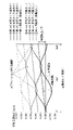
- FIG. 10 is a diagram showing a graph showing on the surface the path of the cutting tool in swing cutting
- FIG. 3 is a control block diagram of the computing device of the machine tool of the present disclosure
- FIG. 4 is a diagram showing numerical parameters used in each calculation unit in the machining state calculation unit of the present disclosure
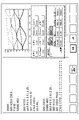
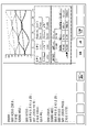
- FIG. 4 is a diagram showing a display example of a display unit in the computing device of the present disclosure
- FIG. 4 is a diagram showing an example of inputting parameters to the display unit of the computing device of the present disclosure
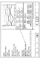
- FIG. 10 illustrates selecting a parameter to change on the display of the computing device of the present disclosure
- FIG. 5 is a diagram showing a display example after changing parameters on the display unit of the computing device of the present disclosure
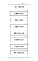
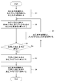
- FIG. 3 is a diagram showing a flow of one embodiment of the present disclosure;
- oscillating cutting As shown in FIG. 1, when the work is machined by rotating the work around the main shaft and sending the cutting tool in contact with the surface of the work in the feed direction, the chips generated during the machining of the work are shredded. For this reason, there is a technique called oscillating cutting that oscillates the cutting tool in the feed direction. Oscillating cutting causes a portion where the cutting in the previous rotation and the cutting in the current rotation overlap each time the spindle rotates. Due to this idling, chips are shredded, and obstacles such as entanglement of chips with the cutting tool can be avoided.
- Fig. 2 shows a graph showing the path of the cutting tool in the above swing cutting on the surface.
- the straight line shows the movement of the contact point between the cutting tool and the workpiece when there is no oscillation.
- the figure shows the movement of the contact point between the cutting tool and the workpiece when the cutting tool is oscillated in the feed direction.
- whiff occurs and chips are shredded. From the graph in FIG. 2 obtained by setting and changing the swing conditions, it can be confirmed whether the previous pass and the current pass intersect, that is, whether the chips are shredded. In the past, trial and error was required to set the path of the tool so that the chips were shredded.
- FIG. 3 is a block diagram of a computing device of a machine tool according to one embodiment of the present disclosure.
- the machine tool calculation device 1 of the present disclosure includes an input unit 11 , a machining block selection unit 12 , a machining condition acquisition unit 20 , a machining state calculation unit 30 , a machining condition reflection unit 40 and a display unit 50 .
- an input unit 11 a machining block selection unit 12 , a machining condition acquisition unit 20 , a machining state calculation unit 30 , a machining condition reflection unit 40 and a display unit 50 .
- the user can input related information for extracting machining conditions and swing conditions to the input unit 11, and select a program block of interest from the machining program of the machine tool by the machining block selection unit 12. can be done.
- the blocks selected by the machining block selection unit 12 include blocks selected by the user as described above and blocks for determining machining conditions and swing conditions related to the blocks selected by the user.
- Information input to the input unit 11 and information about program blocks selected by the processing block selection unit 12 are output to the processing condition acquisition unit 20 and input to the processing condition acquisition unit 20 .
- the machining condition acquisition unit 20 extracts and acquires the machining conditions and swing conditions from the information input from the input unit 11 and machining block selection unit 12 .
- the machining conditions and oscillation conditions acquired by the machining condition acquiring unit 20 include information for uniquely obtaining oscillation frequency, information for uniquely obtaining oscillation amplitude, tool feed rate (mm/min), workpiece diameter, (mm), cutting edge R (mm), tool relief angle (°), and the like.
- the information that uniquely determines the oscillation frequency includes an oscillation frequency multiplier I (multiplier) that indicates the oscillation frequency per rotation of the main shaft.
- the information that uniquely determines the oscillation amplitude includes A swing amplitude magnification factor K (times) is included that indicates the magnitude of the swing swing amplitude with respect to the size of the feed amount per rotation. Further, the feed rate of the tool can be obtained from the rotational speed S (1/min) of the spindle and the transfer amount F (mm/rev) each time. Information such as the above parameters related to the machining conditions and swing conditions extracted and acquired by the machining condition acquisition unit 20 is sent to the machining condition calculation unit 30 , the machining condition reflection unit 40 and the display unit 50 .
- the machining state calculation unit 30 includes a chip shredding determination unit 31, a chip length calculation unit 32, a surface roughness calculation unit 33, an oscillation frequency calculation unit 34, an oscillation amplitude calculation unit 35, A maximum velocity calculator 36 and a maximum acceleration calculator 37 are provided.
- the chip shredding determination unit 31 determines whether or not chips can be shredded from the oscillation frequency magnification I and the oscillation amplitude magnification K.
- the chip length calculator 32 calculates the chip length from the oscillation frequency magnification I and the workpiece diameter.
- the surface roughness calculator 33 calculates the surface roughness from the oscillation frequency magnification I, the oscillation amplitude magnification K, the transfer amount F each time, and the cutting edge R.
- the oscillation frequency calculator 34 calculates the oscillation frequency from the oscillation frequency magnification I and the spindle rotation speed S.
- the swing amplitude calculator 35 calculates the swing amplitude from the swing amplitude magnification K and the transfer amount F each time.
- the maximum speed calculator 36 calculates the maximum speed from the oscillation frequency magnification I, the oscillation amplitude magnification K, the spindle rotation speed S, and the transfer amount F each time.
- the maximum acceleration calculator 37 calculates the maximum acceleration from the oscillation frequency magnification I, the oscillation amplitude magnification K, the spindle rotation speed S, and the transfer amount F each time.
- information on whether chip shredding is possible is sent to the processing condition reflecting unit 40 and also sent to the display unit 50 .
- Numerical data such as chip length, surface roughness, oscillation frequency, oscillation amplitude, maximum velocity and maximum acceleration are sent to the display unit 50 . If the information on whether the chips can be shredded displayed on the display unit 50 is "No", that is, if the chips cannot be shredded appropriately, the user inputs the processing conditions and the swing conditions to the input unit 11.
- Related information for extracting can be newly input. Information newly input to the input unit 11 is sent to the processing condition acquisition unit, and new processing conditions and swing conditions are acquired.
- the machining condition reflection unit 40 reflects the new machining conditions and swing conditions acquired by the machining condition acquisition unit 20 in the blocks of the machining program selected by the machining block selection unit. Even if the information on whether the chips can be shredded displayed on the display unit 50 is "possible", the user can refer to the results (chip length, maximum speed, etc.) of the machining state calculation unit, , the relevant information for extracting the machining conditions and the swing conditions may be newly input and reflected in the blocks of the machining program selected by the machining block selection unit. In addition, it is also possible to inversely calculate rocking conditions for minimizing at least one part in the machining state calculation part 30 and reflect them in the machining condition acquisition part 20 .
- the rocking condition to be minimized is calculated from the selected part in the machining state calculation unit 30 and the relational expression between the machining condition and the rocking condition. At this time, it is also possible to calculate a rocking condition under which chips can be shredded and a selected portion in the machining state calculation unit 30 has a minimum value from a judgment formula for determining whether chips can be shredded.
- the display unit 50 displays the parameters related to the above-described machining conditions and swing conditions acquired by the machining condition acquisition unit 20, and data of the results of machining conditions calculated by the machining condition calculation unit 30.
- the display of machining state result data also includes a graphical display of vibrational motion.
- the user can enter each parameter related to the machining conditions and the swing conditions.
- a block can be specified from , and the specified program block becomes a block selected by the user in the machining block selection unit 12 .
- FIG. 5 shows a chip shredding determination unit 31, a chip length calculation unit 32, a surface roughness calculation unit 33, an oscillation frequency calculation unit 34, an oscillation amplitude calculation unit 35, and a maximum speed calculation unit of the machining state calculation unit 30.
- 36 and the maximum acceleration calculation unit 37 the oscillation frequency magnification I, the oscillation amplitude magnification K, the spindle rotation speed S, the transfer amount F, the workpiece diameter ⁇ , and the cutting edge R in the machining conditions and oscillation conditions, respectively.
- the parameters of the machining conditions and the swing conditions include information on the relief angle (°) and taper angle (°) of the tool.
- the oscillation frequency magnification I, oscillation amplitude K, transfer amount F and spindle rotation speed S are acquired from modal information.
- Modal information is information that, once set by the user, maintains a constant value unless it is set again.
- the cutting edge R and clearance angle are obtained from the modal tool information (T number).
- the workpiece diameter can be obtained from the X coordinate of the selected machining block, and the taper angle can be obtained from the start point and end point of the XZ coordinates of the selected machining block.
- FIG. 6 shows a display example of the display unit 50 in the computing device 1 of the machine tool, and the machining program is displayed on the left side.
- the user designates the dotted line (Z10.0.X17.0;) of the machining program in the machining block selection unit 12 (FIG. 3), and the block related to this line (G00.Z30.0 line from ; to Z10.0 X17.0;) is selected.
- machining conditions and rocking conditions for the blocks of the selected machining program are displayed. Specifically, a waveform diagram showing the path of the cutting tool in the block of the selected machining program is displayed in the upper part. Parameters (oscillation frequency I (times), oscillation amplitude K (times), transfer amount F (mm/rev), spindle speed (min ⁇ 1 ), workpiece ⁇ (mm), taper angle (°), cutting edge R (mm), clearance angle (°)).
- Estimated value of the machining result machined by the block of the selected machining program (whether chip shredding, chip length (mm), average Ra (mm), frequency (Hz), Amplitude (mm), maximum velocity (mm/min), maximum acceleration (mm/min 2 )) are displayed, and frequency (Hz), amplitude (mm), maximum velocity (mm/min), maximum acceleration (mm /min 2 ) below which the machine's operable upper limit is disclosed.
- the user can input the parameters related to the machining conditions and the swing conditions shown in the upper framed portion on the lower right side.
- “0.500” is input to change the oscillation frequency I (times)
- "1.500” is input to change the oscillation amplitude K (times)
- the values of these parameters are inserted into selected blocks of the machining program.
- the oscillation frequency I (double) and the oscillation amplitude K (double) are changed, the G8.5 command in the selected block of the machining program is reedited.
- the machining result calculated by reflecting the values of these parameters in the machining program is shown in the lower framed portion on the lower right side of FIG.
- parameters related to machining conditions and rocking conditions can be easily input in the framed portion on the lower right side of the display section 50 (FIG. 3).
- the parameters are immediately inserted into the selected block of the machining program and reflected in the machining program, and the calculation processing result is immediately displayed in the lower framed portion on the lower right side. Therefore, the user can efficiently change the parameters related to the machining conditions and the swing conditions to appropriate values while predicting the machining result of the calculation processing of the machining program.
- FIG. 8 shows a state in which machining conditions and rocking conditions are input and each part of the machining state calculator is derived.
- the frequency, amplitude, maximum velocity, and maximum acceleration of the machining result are all values below the upper limit values, and the chip shredding is determined as "O".
- the rocking condition for minimizing any one or more sections is reversely calculated and reflected in the machining condition acquisition section 20, one or more of the machining state calculation sections is selected. This time, select maximum acceleration and place the cursor.
- the minimum value setting button is pressed, as shown in FIG. 9, the swing conditions are set such that the maximum acceleration is minimized within the range where chip shredding occurs. That is, along with the maximum acceleration, the values of K, I, frequency, amplitude and maximum velocity have been changed. Since the swing conditions have been changed, the values of each part of the machining state are also updated, and the values of the chip length and average Ra are updated.
- the machining condition acquisition unit acquires machining conditions and swing conditions from the machining block selection unit (step S1). This is done by the user selecting a block from the machining program and selecting the resulting row.
- machining state calculation unit calculates the state result at that time from the acquired machining conditions and rocking conditions (step S2). The result is sent to step 3 below.
- step 3 it is determined whether or not the machining conditions and swing conditions acquired by the machining condition acquiring unit are appropriate based on the state result calculated in step 2 (step S3). If the result of step 3 is YES, that is, if it is determined that the machining conditions and swing conditions are appropriate, step 5 is performed. If the result of step 3 is NO, that is, if it is determined that the machining conditions and swing conditions are not appropriate, the process returns to step 2 via step 4.
- step 4 the machining condition acquisition unit acquires machining conditions and swing conditions from the input unit.
- the user inputs numerical values into the input section of the parameters related to the machining conditions and the swing conditions on the display section.
- step 2 the machining state calculation unit again calculates the state result at that time from the acquired machining conditions and swing conditions, and the calculation result is sent to the next step 3.
- the loop of steps 2, 3, and 4 is repeated until the result in step 3 is YES, that is, until it is determined that the machining conditions and swing conditions are appropriate.
- step 5 the machining program is re-edited by inserting the acquired machining conditions and rocking conditions into the machining program (step 5). Reflect it in the machining program (step 6). In other words, this allows the user to know again the result of determination as to whether the machining conditions and swing conditions are appropriate, and this flow ends.
- the machine tool calculation device of the present disclosure it is easy to input parameters related to the machining conditions and the oscillation conditions. Since the parameters and machining results (status) are displayed on one screen, the user can easily set the optimum machining conditions and oscillation conditions without repeating trial and error. It has a remarkable effect that it can be done.
- calculation device 11 input unit 12 machining block selection unit 20 machining condition acquisition unit 30 machining state calculation unit 31 chip shredding determination unit 32 chip length calculation unit 33 surface roughness calculation unit 34 oscillation frequency calculation unit 35 oscillation amplitude calculation Section 36 Maximum Speed Calculation Section 37 Maximum Acceleration Calculation Section 40 Machining Condition Reflection Section 50 Display Section
Landscapes
- Engineering & Computer Science (AREA)
- Human Computer Interaction (AREA)
- Manufacturing & Machinery (AREA)
- Physics & Mathematics (AREA)
- General Physics & Mathematics (AREA)
- Automation & Control Theory (AREA)
- Numerical Control (AREA)
Abstract
Description
表示部50で表示された切屑細断可否の情報が「可」であった場合でも、加工状態算出部の各結果(切屑長さ、最大速度、等)を参考に、ユーザは、入力部11に、加工条件及び揺動条件を抽出するための関連情報を新たに入力し、加工ブロック選択部が選択した加工プログラムのブロックに反映しても良い。
また、加工状態算出部30中のいずれか1つ以上の部を最小化する揺動条件を逆計算して加工条件取得部20に反映することもできる。加工状態算出部30中の選択された部と加工条件・揺動条件の関係式から最小化される揺動条件が算出される。このとき、さらに切屑細断の可否の判定式から切屑細断可かつ、加工状態算出部30中の選択された部が最小値となる揺動条件を算出してもよい。
11 入力部
12 加工ブロック選択部
20 加工条件取得部
30 加工状態算出部
31 切屑細断判定部
32 切屑長さ算出部
33 表面粗さ算出部
34 揺動周波数算出部
35 揺動振幅算出部
36 最大速度算出部
37 最大加速度算出部
40 加工条件反映部
50 表示部
Claims (14)
- 加工プログラムに基づいて、切削工具とワークを相対的に揺動させながら加工する工作機械の計算装置において、
加工条件及び揺動条件を取得する加工条件取得部と、
前記加工条件取得部で取得した加工条件及び揺動条件から加工状態を算出する加工状態算出部と、
前記加工条件取得部で取得した加工条件及び揺動条件、並びに、前記加工状態算出部で算出した加工状態を表示する表示部と、
前記加工条件取得部で取得した加工条件及び揺動条件を前記加工プログラムに反映させる加工条件反映部と、
を備える計算装置。 - 前記加工状態算出部は、
加工状態を決定した後に、決定した加工状態から加工条件を逆算出し、前記加工条件取得部に反映する機能を備える請求項1に記載の計算装置。 - 前記計算装置は、
ユーザが加工条件及び揺動条件を入力することができる入力部と、
前記加工プログラムから、記加工条件反映部で加工条件及び揺動条件を反映させるブロックが選択される加工ブロック選択部と、
を備え、
前記加工条件取得部は、前記入力部又は前記加工ブロック選択部から、加工条件及び揺動条件を取得する、請求項1又は2に記載の計算装置。 - 前記加工ブロック選択部で選択されるブロックは、前記加工プログラムからユーザが選択したブロック、又は、前記ユーザが選択したブロックに関係する加工条件及び揺動条件を決定するブロックである、請求項3に記載の計算装置。
- 前記加工状態算出部は、
切屑細断の可否を判定する切屑細断判定部と、
前記ワークの切屑の長さを算出する切屑長さ算出部と、
前記ワークの表面粗さを算出する表面粗さ算出部と、
前記切削工具と前記ワークの相対的な揺動における揺動周波数を算出する揺動周波数算出部と、
前記切削工具と前記ワークの相対的な揺動における揺動振幅を算出する揺動振幅算出部と、
前記切削工具と前記ワークの相対的な揺動における最大速度を算出する最大速度算出部と、
前記切削工具と前記ワークの相対的な揺動における最大加速度を算出する最大加速度算出部と、
のうちのいずれか1つ以上を備える請求項1~4のいずれかに記載の計算装置。 - 前記加工条件取得部から前記加工状態算出部の前記切屑細断判定部に、揺動周波数を一意に求められる情報、及び、揺動振幅を一意に求められる情報を含む情報が送出される請求項5に記載の計算装置。
- 前記加工条件取得部から前記加工状態算出部の前記切屑長さ算出部に、揺動周波数を一意に求められる情報、及び、ワーク径を含む情報が送出される請求項5に記載の計算装置。
- 前記加工条件取得部から前記加工状態算出部の前記表面粗さ算出部に、揺動周波数を一意に求められる情報、揺動振幅を一意に求められる情報、工具の送り速度、及び、刃先Rを含む情報が送出される請求項5に記載の計算装置。
- 前記加工条件取得部から前記加工状態算出部の前記揺動周波数算出部に、揺動周波数を一意に求められる情報を含む情報が送出される請求項5に記載の計算装置。
- 前記加工条件取得部から前記加工状態算出部の前記揺動振幅算出部に、揺動振幅を一意に求められる情報を含む情報が送出される請求項5に記載の計算装置。
- 前記加工条件取得部から前記加工状態算出部の前記最大速度算出部に、揺動周波数を一意に求められる情報、揺動振幅を一意に求められる情報、及び、工具の送り速度を含む情報が送出される請求項5に記載の計算装置。
- 前記加工条件取得部から前記加工状態算出部の前記最大加速度算出部に、揺動周波数を一意に求められる情報、揺動振幅を一意に求められる情報、及び、工具の送り速度を含む情報が送出される請求項5に記載の計算装置。
- 前記加工条件取得部から前記表示部に、揺動周波数を一意に求められる情報、及び、揺動振幅を一意に求められる情報を含む情報が送出され
前記表示部において、振動動作をグラフィカルに表示する、請求項1~12のいずれかに記載の計算装置。 - コンピュータに、加工プログラムに基づいて切削工具とワークを相対的に揺動させながら加工する工作機械における計算を実行させる計算プログラムであって、
前記コンピュータに
加工条件及び揺動条件を取得する加工条件取得ステップと、
前記加工条件取得ステップで取得した加工条件及び揺動条件から加工状態を算出する加工状態算出ステップと、
前記加工条件取得ステップで取得した加工条件及び揺動条件、並びに、前記加工状態算出ステップで算出した加工状態を表示する表示ステップと、
前記加工条件取得ステップで取得した加工条件及び揺動条件を、前記加工プログラムに反映させる加工条件反映ステップと、
を実行させる計算プログラム。
Priority Applications (4)
| Application Number | Priority Date | Filing Date | Title |
|---|---|---|---|
| DE112022000213.1T DE112022000213T5 (de) | 2021-02-26 | 2022-02-22 | Computer |
| JP2023502425A JP7633369B2 (ja) | 2021-02-26 | 2022-02-22 | 計算装置 |
| CN202280015745.8A CN116897321A (zh) | 2021-02-26 | 2022-02-22 | 计算装置 |
| US18/256,874 US20240019837A1 (en) | 2021-02-26 | 2022-02-22 | Computer |
Applications Claiming Priority (2)
| Application Number | Priority Date | Filing Date | Title |
|---|---|---|---|
| JP2021030527 | 2021-02-26 | ||
| JP2021-030527 | 2021-02-26 |
Publications (1)
| Publication Number | Publication Date |
|---|---|
| WO2022181594A1 true WO2022181594A1 (ja) | 2022-09-01 |
Family
ID=83048178
Family Applications (1)
| Application Number | Title | Priority Date | Filing Date |
|---|---|---|---|
| PCT/JP2022/007183 Ceased WO2022181594A1 (ja) | 2021-02-26 | 2022-02-22 | 計算装置 |
Country Status (5)
| Country | Link |
|---|---|
| US (1) | US20240019837A1 (ja) |
| JP (1) | JP7633369B2 (ja) |
| CN (1) | CN116897321A (ja) |
| DE (1) | DE112022000213T5 (ja) |
| WO (1) | WO2022181594A1 (ja) |
Cited By (8)
| Publication number | Priority date | Publication date | Assignee | Title |
|---|---|---|---|---|
| JP2023000009A (ja) * | 2021-06-17 | 2023-01-04 | スター精密株式会社 | 工作機械のための振動切削条件設定装置 |
| JP7252426B1 (ja) * | 2022-09-30 | 2023-04-04 | ファナック株式会社 | 工作機械の制御装置及び工作機械の表示装置 |
| JPWO2024062544A1 (ja) * | 2022-09-21 | 2024-03-28 | ||
| WO2024062607A1 (ja) * | 2022-09-22 | 2024-03-28 | ファナック株式会社 | 工作機械の制御装置 |
| WO2024105842A1 (ja) * | 2022-11-17 | 2024-05-23 | ファナック株式会社 | 工作機械の制御装置 |
| WO2024232102A1 (ja) * | 2023-05-11 | 2024-11-14 | ファナック株式会社 | 工作機械の表示装置及び制御システム |
| WO2024232099A1 (ja) * | 2023-05-11 | 2024-11-14 | ファナック株式会社 | 計算装置 |
| JP7710621B1 (ja) * | 2024-05-27 | 2025-07-18 | 三菱電機株式会社 | 設定支援装置、数値制御装置、設定支援方法およびプログラム |
Citations (2)
| Publication number | Priority date | Publication date | Assignee | Title |
|---|---|---|---|---|
| JPH07227720A (ja) * | 1993-12-24 | 1995-08-29 | Toyota Motor Corp | 放電加工方法 |
| JP6546707B2 (ja) * | 2016-12-22 | 2019-07-17 | シチズン時計株式会社 | 工作機械およびその制御装置 |
Family Cites Families (7)
| Publication number | Priority date | Publication date | Assignee | Title |
|---|---|---|---|---|
| EP3213848B1 (en) * | 2014-10-28 | 2024-09-18 | Mitsubishi Electric Corporation | Numerical control device |
| JP6721307B2 (ja) * | 2015-09-16 | 2020-07-15 | ファナック株式会社 | 複数軸を備えた工作機械の制御装置 |
| JP6625914B2 (ja) * | 2016-03-17 | 2019-12-25 | ファナック株式会社 | 機械学習装置、レーザ加工システムおよび機械学習方法 |
| JP6708690B2 (ja) * | 2018-04-05 | 2020-06-10 | ファナック株式会社 | 表示装置 |
| JP6802212B2 (ja) * | 2018-04-24 | 2020-12-16 | ファナック株式会社 | 表示装置 |
| JP6735317B2 (ja) * | 2018-06-21 | 2020-08-05 | Dmg森精機株式会社 | 工作機械、制御方法、および制御プログラム |
| JP7227720B2 (ja) * | 2018-09-06 | 2023-02-22 | 日立Astemo株式会社 | 車両制御装置、車両制御方法、及び車両制御システム |
-
2022
- 2022-02-22 DE DE112022000213.1T patent/DE112022000213T5/de active Pending
- 2022-02-22 JP JP2023502425A patent/JP7633369B2/ja active Active
- 2022-02-22 US US18/256,874 patent/US20240019837A1/en active Pending
- 2022-02-22 CN CN202280015745.8A patent/CN116897321A/zh active Pending
- 2022-02-22 WO PCT/JP2022/007183 patent/WO2022181594A1/ja not_active Ceased
Patent Citations (2)
| Publication number | Priority date | Publication date | Assignee | Title |
|---|---|---|---|---|
| JPH07227720A (ja) * | 1993-12-24 | 1995-08-29 | Toyota Motor Corp | 放電加工方法 |
| JP6546707B2 (ja) * | 2016-12-22 | 2019-07-17 | シチズン時計株式会社 | 工作機械およびその制御装置 |
Cited By (12)
| Publication number | Priority date | Publication date | Assignee | Title |
|---|---|---|---|---|
| JP2023000009A (ja) * | 2021-06-17 | 2023-01-04 | スター精密株式会社 | 工作機械のための振動切削条件設定装置 |
| JP7755126B2 (ja) | 2021-06-17 | 2025-10-16 | スター精密株式会社 | 工作機械のための振動切削条件設定装置 |
| JPWO2024062544A1 (ja) * | 2022-09-21 | 2024-03-28 | ||
| WO2024062544A1 (ja) * | 2022-09-21 | 2024-03-28 | ファナック株式会社 | 工作機械の表示装置 |
| WO2024062607A1 (ja) * | 2022-09-22 | 2024-03-28 | ファナック株式会社 | 工作機械の制御装置 |
| JPWO2024062607A1 (ja) * | 2022-09-22 | 2024-03-28 | ||
| JP7252426B1 (ja) * | 2022-09-30 | 2023-04-04 | ファナック株式会社 | 工作機械の制御装置及び工作機械の表示装置 |
| WO2024069951A1 (ja) * | 2022-09-30 | 2024-04-04 | ファナック株式会社 | 工作機械の制御装置及び工作機械の表示装置 |
| WO2024105842A1 (ja) * | 2022-11-17 | 2024-05-23 | ファナック株式会社 | 工作機械の制御装置 |
| WO2024232102A1 (ja) * | 2023-05-11 | 2024-11-14 | ファナック株式会社 | 工作機械の表示装置及び制御システム |
| WO2024232099A1 (ja) * | 2023-05-11 | 2024-11-14 | ファナック株式会社 | 計算装置 |
| JP7710621B1 (ja) * | 2024-05-27 | 2025-07-18 | 三菱電機株式会社 | 設定支援装置、数値制御装置、設定支援方法およびプログラム |
Also Published As
| Publication number | Publication date |
|---|---|
| CN116897321A (zh) | 2023-10-17 |
| DE112022000213T5 (de) | 2023-08-17 |
| JP7633369B2 (ja) | 2025-02-19 |
| JPWO2022181594A1 (ja) | 2022-09-01 |
| US20240019837A1 (en) | 2024-01-18 |
Similar Documents
| Publication | Publication Date | Title |
|---|---|---|
| WO2022181594A1 (ja) | 計算装置 | |
| JP6744815B2 (ja) | 工作機械の制御装置および工作機械 | |
| JP6843313B1 (ja) | 制御システム | |
| JP7620034B2 (ja) | 表示装置及びコンピュータプログラム | |
| JP7444697B2 (ja) | 数値制御装置、制御プログラム及び制御方法 | |
| CN104227497A (zh) | 旋转切削工具的实时设定转速的方法和控制装置 | |
| TW201619726A (zh) | 數値控制裝置 | |
| CN108604089A (zh) | 加工状态显示装置 | |
| JP7252426B1 (ja) | 工作機械の制御装置及び工作機械の表示装置 | |
| CN112130524A (zh) | 数值控制装置、程序记录介质以及控制方法 | |
| WO2015037143A1 (ja) | 工具経路評価方法、工具経路生成方法、及び工具経路生成装置 | |
| JP2021066005A (ja) | 数値制御装置、プログラム及び制御方法 | |
| JP6499707B2 (ja) | シミュレーション装置、プログラム生成装置、制御装置およびコンピュータの表示方法 | |
| JP4639058B2 (ja) | ねじ切り加工装置 | |
| WO2024062544A1 (ja) | 工作機械の表示装置 | |
| JP7410187B2 (ja) | 工作機械の制御装置 | |
| CN111240264B (zh) | 数值控制装置、程序记录介质以及控制方法 | |
| JP7039772B1 (ja) | 表示装置、工作機械、および表示方法 | |
| JP7131454B2 (ja) | 数値制御装置、工作機械、制御プログラム、及び記憶媒体 | |
| CN121175631A (zh) | 机床的显示装置 | |
| JP7799048B2 (ja) | 工作機械の制御装置 | |
| JP7827878B2 (ja) | 工作機械の制御装置及び工作機械の表示装置 | |
| JP2002205243A (ja) | 回転工具による加工方法 | |
| CN120282849A (zh) | 机床的控制装置 | |
| CN121039588A (zh) | 机床的显示装置以及程序 |
Legal Events
| Date | Code | Title | Description |
|---|---|---|---|
| 121 | Ep: the epo has been informed by wipo that ep was designated in this application |
Ref document number: 22759630 Country of ref document: EP Kind code of ref document: A1 |
|
| ENP | Entry into the national phase |
Ref document number: 2023502425 Country of ref document: JP Kind code of ref document: A |
|
| WWE | Wipo information: entry into national phase |
Ref document number: 18256874 Country of ref document: US |
|
| WWE | Wipo information: entry into national phase |
Ref document number: 202280015745.8 Country of ref document: CN |
|
| 122 | Ep: pct application non-entry in european phase |
Ref document number: 22759630 Country of ref document: EP Kind code of ref document: A1 |