WO2022181525A1 - 通信システムおよび通信端末 - Google Patents
通信システムおよび通信端末 Download PDFInfo
- Publication number
- WO2022181525A1 WO2022181525A1 PCT/JP2022/006883 JP2022006883W WO2022181525A1 WO 2022181525 A1 WO2022181525 A1 WO 2022181525A1 JP 2022006883 W JP2022006883 W JP 2022006883W WO 2022181525 A1 WO2022181525 A1 WO 2022181525A1
- Authority
- WO
- WIPO (PCT)
- Prior art keywords
- base station
- multicast
- communication
- leg
- data
- Prior art date
Links
- 238000004891 communication Methods 0.000 title claims abstract description 249
- 238000005516 engineering process Methods 0.000 claims abstract description 13
- 230000005540 biological transmission Effects 0.000 claims description 136
- 230000010354 integration Effects 0.000 claims 1
- 230000011664 signaling Effects 0.000 description 69
- 238000010586 diagram Methods 0.000 description 58
- 238000012545 processing Methods 0.000 description 51
- 238000000034 method Methods 0.000 description 34
- 230000001960 triggered effect Effects 0.000 description 24
- 230000004048 modification Effects 0.000 description 21
- 238000012986 modification Methods 0.000 description 21
- 238000007726 management method Methods 0.000 description 14
- 230000008569 process Effects 0.000 description 14
- 230000004044 response Effects 0.000 description 13
- 238000007792 addition Methods 0.000 description 11
- 238000005259 measurement Methods 0.000 description 11
- 230000015654 memory Effects 0.000 description 11
- 230000006870 function Effects 0.000 description 10
- 230000000694 effects Effects 0.000 description 9
- 238000012937 correction Methods 0.000 description 7
- 238000012217 deletion Methods 0.000 description 7
- 230000037430 deletion Effects 0.000 description 7
- 238000013468 resource allocation Methods 0.000 description 7
- 101100465000 Mus musculus Prag1 gene Proteins 0.000 description 6
- 230000008859 change Effects 0.000 description 6
- 238000006243 chemical reaction Methods 0.000 description 6
- 238000013146 percutaneous coronary intervention Methods 0.000 description 6
- 238000012546 transfer Methods 0.000 description 5
- 101150096310 SIB1 gene Proteins 0.000 description 3
- 239000000969 carrier Substances 0.000 description 3
- 230000009849 deactivation Effects 0.000 description 3
- 230000007812 deficiency Effects 0.000 description 3
- 238000013461 design Methods 0.000 description 3
- 230000007774 longterm Effects 0.000 description 3
- 239000011159 matrix material Substances 0.000 description 3
- 230000006978 adaptation Effects 0.000 description 2
- 230000002776 aggregation Effects 0.000 description 2
- 238000004220 aggregation Methods 0.000 description 2
- 230000008901 benefit Effects 0.000 description 2
- 230000006866 deterioration Effects 0.000 description 2
- 230000009977 dual effect Effects 0.000 description 2
- 230000007257 malfunction Effects 0.000 description 2
- 238000010295 mobile communication Methods 0.000 description 2
- 230000000737 periodic effect Effects 0.000 description 2
- 238000000926 separation method Methods 0.000 description 2
- 230000001360 synchronised effect Effects 0.000 description 2
- 241001229889 Metis Species 0.000 description 1
- 230000004913 activation Effects 0.000 description 1
- 238000004364 calculation method Methods 0.000 description 1
- 230000001413 cellular effect Effects 0.000 description 1
- 238000012508 change request Methods 0.000 description 1
- 230000006835 compression Effects 0.000 description 1
- 238000007906 compression Methods 0.000 description 1
- 125000004122 cyclic group Chemical group 0.000 description 1
- 238000013523 data management Methods 0.000 description 1
- 230000000977 initiatory effect Effects 0.000 description 1
- 208000018910 keratinopathic ichthyosis Diseases 0.000 description 1
- 230000008520 organization Effects 0.000 description 1
- 230000002085 persistent effect Effects 0.000 description 1
- 230000010076 replication Effects 0.000 description 1
- 239000004065 semiconductor Substances 0.000 description 1
- 238000010408 sweeping Methods 0.000 description 1
- 208000037918 transfusion-transmitted disease Diseases 0.000 description 1
- 238000012384 transportation and delivery Methods 0.000 description 1
- 230000005641 tunneling Effects 0.000 description 1
Images


Classifications
-
- H—ELECTRICITY
- H04—ELECTRIC COMMUNICATION TECHNIQUE
- H04W—WIRELESS COMMUNICATION NETWORKS
- H04W36/00—Hand-off or reselection arrangements
- H04W36/06—Reselecting a communication resource in the serving access point
-
- H—ELECTRICITY
- H04—ELECTRIC COMMUNICATION TECHNIQUE
- H04W—WIRELESS COMMUNICATION NETWORKS
- H04W28/00—Network traffic management; Network resource management
- H04W28/02—Traffic management, e.g. flow control or congestion control
- H04W28/04—Error control
-
- H—ELECTRICITY
- H04—ELECTRIC COMMUNICATION TECHNIQUE
- H04L—TRANSMISSION OF DIGITAL INFORMATION, e.g. TELEGRAPHIC COMMUNICATION
- H04L1/00—Arrangements for detecting or preventing errors in the information received
- H04L1/12—Arrangements for detecting or preventing errors in the information received by using return channel
- H04L1/16—Arrangements for detecting or preventing errors in the information received by using return channel in which the return channel carries supervisory signals, e.g. repetition request signals
- H04L1/18—Automatic repetition systems, e.g. Van Duuren systems
- H04L1/1812—Hybrid protocols; Hybrid automatic repeat request [HARQ]
- H04L1/1819—Hybrid protocols; Hybrid automatic repeat request [HARQ] with retransmission of additional or different redundancy
-
- H—ELECTRICITY
- H04—ELECTRIC COMMUNICATION TECHNIQUE
- H04L—TRANSMISSION OF DIGITAL INFORMATION, e.g. TELEGRAPHIC COMMUNICATION
- H04L1/00—Arrangements for detecting or preventing errors in the information received
- H04L1/12—Arrangements for detecting or preventing errors in the information received by using return channel
- H04L1/16—Arrangements for detecting or preventing errors in the information received by using return channel in which the return channel carries supervisory signals, e.g. repetition request signals
- H04L1/18—Automatic repetition systems, e.g. Van Duuren systems
- H04L1/1829—Arrangements specially adapted for the receiver end
- H04L1/1848—Time-out mechanisms
-
- H—ELECTRICITY
- H04—ELECTRIC COMMUNICATION TECHNIQUE
- H04L—TRANSMISSION OF DIGITAL INFORMATION, e.g. TELEGRAPHIC COMMUNICATION
- H04L1/00—Arrangements for detecting or preventing errors in the information received
- H04L1/12—Arrangements for detecting or preventing errors in the information received by using return channel
- H04L1/16—Arrangements for detecting or preventing errors in the information received by using return channel in which the return channel carries supervisory signals, e.g. repetition request signals
- H04L1/18—Automatic repetition systems, e.g. Van Duuren systems
- H04L1/1867—Arrangements specially adapted for the transmitter end
- H04L1/188—Time-out mechanisms
-
- H—ELECTRICITY
- H04—ELECTRIC COMMUNICATION TECHNIQUE
- H04L—TRANSMISSION OF DIGITAL INFORMATION, e.g. TELEGRAPHIC COMMUNICATION
- H04L1/00—Arrangements for detecting or preventing errors in the information received
- H04L1/12—Arrangements for detecting or preventing errors in the information received by using return channel
- H04L1/16—Arrangements for detecting or preventing errors in the information received by using return channel in which the return channel carries supervisory signals, e.g. repetition request signals
- H04L1/18—Automatic repetition systems, e.g. Van Duuren systems
- H04L1/1867—Arrangements specially adapted for the transmitter end
- H04L1/1887—Scheduling and prioritising arrangements
-
- H—ELECTRICITY
- H04—ELECTRIC COMMUNICATION TECHNIQUE
- H04W—WIRELESS COMMUNICATION NETWORKS
- H04W24/00—Supervisory, monitoring or testing arrangements
- H04W24/10—Scheduling measurement reports ; Arrangements for measurement reports
-
- H—ELECTRICITY
- H04—ELECTRIC COMMUNICATION TECHNIQUE
- H04W—WIRELESS COMMUNICATION NETWORKS
- H04W28/00—Network traffic management; Network resource management
- H04W28/02—Traffic management, e.g. flow control or congestion control
- H04W28/0231—Traffic management, e.g. flow control or congestion control based on communication conditions
-
- H—ELECTRICITY
- H04—ELECTRIC COMMUNICATION TECHNIQUE
- H04W—WIRELESS COMMUNICATION NETWORKS
- H04W4/00—Services specially adapted for wireless communication networks; Facilities therefor
- H04W4/06—Selective distribution of broadcast services, e.g. multimedia broadcast multicast service [MBMS]; Services to user groups; One-way selective calling services
-
- H—ELECTRICITY
- H04—ELECTRIC COMMUNICATION TECHNIQUE
- H04W—WIRELESS COMMUNICATION NETWORKS
- H04W84/00—Network topologies
- H04W84/02—Hierarchically pre-organised networks, e.g. paging networks, cellular networks, WLAN [Wireless Local Area Network] or WLL [Wireless Local Loop]
- H04W84/04—Large scale networks; Deep hierarchical networks
- H04W84/042—Public Land Mobile systems, e.g. cellular systems
- H04W84/047—Public Land Mobile systems, e.g. cellular systems using dedicated repeater stations
-
- H—ELECTRICITY
- H04—ELECTRIC COMMUNICATION TECHNIQUE
- H04W—WIRELESS COMMUNICATION NETWORKS
- H04W88/00—Devices specially adapted for wireless communication networks, e.g. terminals, base stations or access point devices
- H04W88/08—Access point devices
- H04W88/085—Access point devices with remote components
-
- H—ELECTRICITY
- H04—ELECTRIC COMMUNICATION TECHNIQUE
- H04L—TRANSMISSION OF DIGITAL INFORMATION, e.g. TELEGRAPHIC COMMUNICATION
- H04L1/00—Arrangements for detecting or preventing errors in the information received
- H04L2001/0092—Error control systems characterised by the topology of the transmission link
- H04L2001/0096—Channel splitting in point-to-point links
-
- H—ELECTRICITY
- H04—ELECTRIC COMMUNICATION TECHNIQUE
- H04W—WIRELESS COMMUNICATION NETWORKS
- H04W36/00—Hand-off or reselection arrangements
- H04W36/0005—Control or signalling for completing the hand-off
- H04W36/0055—Transmission or use of information for re-establishing the radio link
- H04W36/0058—Transmission of hand-off measurement information, e.g. measurement reports
Definitions
- This disclosure relates to wireless communication technology.
- LTE Long Term Evolution
- SAE System Architecture Evolution
- OFDM Orthogonal Frequency Division Multiplexing
- SC-FDMA Single Carrier Frequency Division Multiple Access
- LTE does not include circuit switching and is only a packet communication method.
- FIG. 1 is an explanatory diagram showing the structure of a radio frame used in an LTE communication system.
- one radio frame is 10 ms.
- a radio frame is divided into 10 equally sized subframes.
- a subframe is divided into two equal-sized slots.
- a downlink synchronization signal is included in the first and sixth subframes of each radio frame.
- Synchronization signals include a primary synchronization signal (P-SS) and a secondary synchronization signal (S-SS).
- Non-Patent Document 1 (Chapter 5) describes the decisions made by 3GPP regarding the channel configuration in the LTE system. It is assumed that CSG (Closed Subscriber Group) cells also use the same channel configuration as non-CSG cells.
- a physical broadcast channel is a communication terminal device such as a base station device (hereinafter sometimes simply referred to as a "base station”) to a mobile terminal device (hereinafter sometimes simply referred to as a “mobile terminal”). (hereinafter sometimes simply referred to as "communication terminal”).
- a BCH transport block is mapped to 4 subframes in a 40 ms interval. There is no explicit signaling of 40ms timing.
- PCFICH Physical Control Format Indicator Channel
- the PCFICH notifies the communication terminal from the base station of the number of OFDM (Orthogonal Frequency Division Multiplexing) symbols used for PDCCHs.
- PCFICH is transmitted every subframe.
- a Physical Downlink Control Channel is a channel for downlink transmission from a base station to a communication terminal.
- PDCCH includes resource allocation information for a downlink shared channel (DL-SCH), which is one of the transport channels described later, and paging channel (PCH), which is one of the transport channels described later. ) and HARQ (Hybrid Automatic Repeat ReQuest) information on DL-SCH.
- DL-SCH downlink shared channel
- PCH paging channel
- HARQ Hybrid Automatic Repeat ReQuest
- PDCCH carries an uplink scheduling grant.
- the PDCCH carries Ack (Acknowledgment)/Nack (Negative Acknowledgment), which are response signals to uplink transmission.
- PDCCH is also called L1/L2 control signal.
- a physical downlink shared channel is a channel for downlink transmission from a base station to a communication terminal.
- a downlink shared channel (DL-SCH), which is a transport channel, and a PCH, which is a transport channel, are mapped to the PDSCH.
- a Physical Multicast Channel is a channel for downlink transmission from a base station to a communication terminal.
- a multicast channel (Multicast Channel: MCH), which is a transport channel, is mapped to PMCH.
- a physical uplink control channel is a channel for uplink transmission from a communication terminal to a base station.
- PUCCH carries Ack/Nack, which is a response signal for downlink transmission.
- PUCCH carries CSI (Channel State Information).
- CSI is composed of RI (Rank Indicator), PMI (Precoding Matrix Indicator), and CQI (Channel Quality Indicator) reports.
- RI is rank information of a channel matrix in MIMO.
- PMI is precoding weight matrix information used in MIMO.
- CQI is quality information indicating the quality of received data or communication channel quality.
- PUCCH also carries a scheduling request (SR).
- SR scheduling request
- a physical uplink shared channel is a channel for uplink transmission from a communication terminal to a base station.
- An uplink shared channel (UL-SCH), which is one of transport channels, is mapped to the PUSCH.
- a Physical Hybrid ARQ Indicator Channel is a channel for downlink transmission from a base station to a communication terminal.
- PHICH carries Ack/Nack, which is a response signal to uplink transmission.
- a physical random access channel is a channel for uplink transmission from a communication terminal to a base station. PRACH carries a random access preamble.
- a downlink reference signal (reference signal: RS) is a symbol known as an LTE communication system.
- the following five types of downlink reference signals are defined.
- Cell-specific reference signal (CRS), MBSFN reference signal (MBSFN reference signal), data demodulation reference signal (DM-RS) which is UE-specific reference signal (UE-specific reference signal) , Positioning Reference Signal (PRS), Channel State Information Reference Signal (CSI-RS).
- RSRP reference signal received power
- the uplink reference signal is also a symbol known as an LTE communication system.
- the following two types of uplink reference signals are defined. They are a data demodulation reference signal (DM-RS) and a sounding reference signal (SRS).
- DM-RS data demodulation reference signal
- SRS sounding reference signal
- Non-Patent Document 1 (Chapter 5) will be explained.
- the broadcast channel (BCH) is broadcast over the entire coverage of the base station (cell).
- BCH is mapped to a Physical Broadcast Channel (PBCH).
- PBCH Physical Broadcast Channel
- HARQ Hybrid ARQ
- DL-SCH downlink shared channel
- the DL-SCH can be broadcast to the entire coverage of the base station (cell).
- DL-SCH supports dynamic or semi-static resource allocation.
- Semi-static resource allocation is also called persistent scheduling.
- DL-SCH supports discontinuous reception (DRX) of communication terminals in order to reduce the power consumption of communication terminals.
- the DL-SCH is mapped onto a physical downlink shared channel (PDSCH).
- PDSCH physical downlink shared channel
- a paging channel supports DRX of a communication terminal in order to enable low power consumption of the communication terminal.
- the PCH is required to be broadcast to the entire coverage of the base station (cell).
- the PCH is dynamically mapped to a physical resource such as a Physical Downlink Shared Channel (PDSCH) that can be used for traffic.
- PDSCH Physical Downlink Shared Channel
- a multicast channel is used for broadcasting to the entire coverage of a base station (cell).
- the MCH supports SFN combining of MBMS (Multimedia Broadcast Multicast Service) services (MTCH and MCCH) in multi-cell transmission.
- MCH supports semi-static resource allocation.
- MCH is mapped to PMCH.
- HARQ Hybrid ARQ
- PUSCH physical uplink shared channel
- RACH random access channel
- PRACH Physical Random Access Channel
- HARQ is a technique for improving the communication quality of a transmission line by combining automatic repeat request (ARQ) and error correction (Forward Error Correction).
- ARQ automatic repeat request
- FEC Correction Forward Error Correction
- HARQ has the advantage that error correction functions effectively by retransmission even for a transmission path whose communication quality changes. In particular, it is possible to further improve the quality by combining the reception result of the initial transmission and the reception result of the retransmission at the time of retransmission.
- BCCH broadcast control channel
- BCH broadcast channel
- DL-SCH downlink shared channel
- a paging control channel is a downlink channel for transmitting changes in paging information and system information.
- PCCH is used when the network does not know the cell location of the communication terminal.
- a logical channel, PCCH is mapped to a transport channel, a paging channel (PCH).
- a common control channel is a channel for transmission control information between a communication terminal and a base station. CCCH is used when the communication terminal does not have an RRC connection with the network.
- CCCH is mapped to a downlink shared channel (DL-SCH), which is a transport channel.
- DL-SCH downlink shared channel
- UL-SCH uplink shared channel
- a multicast control channel is a downlink channel for one-to-many transmission.
- MCCH is used for transmission of MBMS control information for one or several MTCHs from the network to communication terminals.
- MCCH is used only for communication terminals that are receiving MBMS.
- MCCH is mapped to a multicast channel (MCH), which is a transport channel.
- a dedicated control channel is a channel that transmits dedicated control information between a communication terminal and a network on a one-to-one basis.
- DCCH is used when the communication terminal is in an RRC connection.
- DCCH is mapped to an uplink shared channel (UL-SCH) in uplink, and mapped to a downlink shared channel (DL-SCH) in downlink.
- UL-SCH uplink shared channel
- DL-SCH downlink shared channel
- a dedicated traffic channel is a one-to-one communication channel to a dedicated communication terminal for transmitting user information.
- DTCH exists in both uplink and downlink.
- the DTCH is mapped to an uplink shared channel (UL-SCH) in uplink, and mapped to a downlink shared channel (DL-SCH) in downlink.
- UL-SCH uplink shared channel
- DL-SCH downlink shared channel
- a multicast traffic channel is a downlink channel for transmitting traffic data from a network to communication terminals.
- MTCH is a channel used only by communication terminals that are receiving MBMS.
- MTCH is mapped to a multicast channel (MCH).
- CGI is a Cell Global Identifier.
- ECGI is an E-UTRAN Cell Global Identifier.
- LTE Long Term Evolution Advanced
- UMTS Universal Mobile Telecommunication System
- CSG Cell Subscriber Group
- Communication terminal location tracking is performed in units of areas consisting of one or more cells. Position tracking is performed to track the position of the communication terminal even in a standby state and to call the communication terminal, in other words, to enable the communication terminal to receive a call.
- the area for position tracking of this communication terminal is called a tracking area.
- LTE-A Long Term Evolution Advanced
- CA Carrier Aggregation
- the UE When CA is configured, the UE, which is a communication terminal, has a network (Network: NW) and only one RRC connection. In an RRC connection, one serving cell provides NAS mobility information and security inputs. This cell is called a primary cell (PCell).
- PCell In the downlink, the carrier corresponding to the PCell is the downlink primary component carrier (DL PCC).
- DL PCC downlink primary component carrier
- UPC uplink primary component carrier
- a secondary cell is configured together with the PCell to form a set of serving cells.
- the carrier corresponding to the SCell is the Downlink Secondary Component Carrier (DL SCC).
- the carrier corresponding to the SCell is the uplink secondary component carrier (UL SCC).
- a serving cell set consisting of one PCell and one or more SCells is configured for one UE.
- LTE-A new technologies in LTE-A include technology that supports wider bands (wider bandwidth extension) and coordinated multiple point transmission and reception (CoMP) technology.
- CoMP under consideration for LTE-A in 3GPP is described in Non-Patent Document 1.
- small-scale base station devices small-scale base station devices
- technologies such as installing a large number of small eNBs and configuring a large number of small cells to improve frequency utilization efficiency and increase communication capacity are being studied.
- DC dual connectivity
- eNBs that perform dual connectivity (DC)
- MeNB master eNB
- SeNB secondary eNB
- the volume of mobile network traffic is on the rise, and communication speeds are also increasing. Once full-scale operation of LTE and LTE-A is started, it is expected that the communication speed will be further increased.
- 5G 5th generation radio access system
- METIS a 5th generation radio access system
- the 5G radio access system Compared to the LTE system, the 5G radio access system has 1000 times the system capacity, 100 times the data transmission speed, 1/10th the data processing delay, and 100 times the number of simultaneous connections of communication terminals. As a requirement, it is necessary to further reduce power consumption and reduce the cost of the device.
- the NR system is being studied based on the LTE and LTE-A systems, but the following changes and additions have been made to the LTE and LTE-A systems.
- OFDM is used in the downlink direction
- OFDM is used in the uplink direction
- DFT-s-OFDM DFT-spread-OFDM
- NR In NR, cell coverage is ensured by forming a narrow beam-shaped transmission/reception range (beamforming) and changing the direction of the beam (beam sweeping).
- Various subcarrier intervals that is, various numerologies are supported in the NR frame configuration.
- one subframe is 1 millisecond and one slot is composed of 14 symbols regardless of numerology.
- the number of slots included in one subframe is one in numerology with a subcarrier interval of 15 kHz, and increases in proportion to the subcarrier interval in other numerologies (Non-Patent Document 13 (3GPP TS38.211 )reference).
- the downlink synchronization signal in NR is transmitted from the base station as a synchronization signal burst (hereinafter sometimes referred to as an SS burst) with a predetermined period and a predetermined duration.
- the SS burst is composed of synchronization signal blocks (Synchronization Signal Blocks: hereinafter sometimes referred to as SS blocks) for each beam of the base station.
- the base station transmits the SS block of each beam by changing the beam within the duration of the SS burst.
- the SS block consists of P-SS, S-SS and PBCH.
- phase tracking reference signal a phase tracking reference signal (PTRS) as a downlink reference signal for NR.
- the PTRS is added to the uplink reference signal as well as the downlink.
- SFI Slot Format Indication
- BWP Bandwidth Part
- SL Side Link
- EPS Evolved Packet System
- 3GPP is considering several new technologies. For example, multicast using NR is under study. In multicast using NR, for example, a reliable multicast method, dynamic switching between point-to-multipoint (PTM) transmission and point-to-point (PTP) transmission is being studied. (See Non-Patent Documents 24, 25, and 26).
- PTM point-to-multipoint
- PTP point-to-point
- a PDCP (Packet Data Convergence Protocol) status report may be used in switching between the PTM leg and the PTP leg.
- sending a PDCP status report from the UE to the base station requires an indication from the base station.
- the UE transmits a PDCP status report to the base station in response to an instruction such as DRB (Data Radio Bearer) modification from the base station (see Non-Patent Documents 19 and 27). Therefore, for example, if the UE fails to receive some PDCP PDUs (Protocol Data Units) consisting of multicast data, the UE cannot send a PDCP status report to the base station, resulting in A problem arises that the situation of lack of multicast data cannot be resolved.
- PDCP PDUs Protocol Data Units
- one object of the present disclosure is to realize a communication system that can quickly ensure reliability in multicast.
- a communication system includes a base station compatible with New Radio Access Technology and a communication terminal capable of performing multicast communication with the base station.
- Reception status information which is information about status, is transmitted to the communicating base station, and the base station controls retransmission of data to the communication terminal based on the reception status information.
- FIG. 2 is an explanatory diagram showing the configuration of a radio frame used in an LTE communication system
- 1 is a block diagram showing the overall configuration of an LTE-based communication system 200 under discussion in 3GPP
- FIG. 1 is a block diagram showing the overall configuration of an NR-based communication system 210 under discussion in 3GPP
- FIG. 3 is a block diagram of DC with eNB and gNB connecting to EPC
- FIG. 4 is a block diagram of DC by gNB connected to NG core
- FIG. 4 is a block diagram of DC by eNB and gNB connecting to NG core
- FIG. 4 is a block diagram of DC by eNB and gNB connecting to NG core
- 3 is a block diagram showing the configuration of mobile terminal 202 shown in FIG. 2.
- FIG. 3 is a block diagram showing the configuration of base station 203 shown in FIG. 2.
- FIG. It is a block diagram which shows the structure of MME. It is a block diagram which shows the structure of a 5GC part.
- FIG. 2 is a flowchart showing an overview from cell search to standby operation performed by a communication terminal (UE) in an LTE-based communication system;
- FIG. 1 is a diagram showing an example of a cell configuration in an NR system;
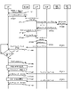
- FIG. FIG. 4 is a sequence diagram showing operations of switching from a PTM leg to a PTP leg and from a PTP leg to a PTM leg in multicast transmission, according to Embodiment 1;
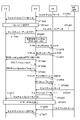
- FIG. 10 is a sequence diagram showing another example of the operation of switching from the PTM leg to the PTP leg and from the PTP leg to the PTM leg in multicast transmission, according to the first embodiment
- FIG. 4 is a sequence diagram showing multicast operations in which a PTM leg and a PTP leg are used simultaneously, according to the first embodiment
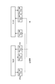
- FIG. 4 is a configuration diagram of a PDCP entity and an RLC entity used in multicast using a PTM leg and/or a PTP leg, regarding Modification 1 of Embodiment 1
- FIG. 10 is a diagram showing another example of configurations of a PDCP entity and an RLC entity used in multicast using a PTM leg and/or a PTP leg, in Modification 1 of Embodiment 1;
- FIG. 10 is a diagram showing another example of configurations of a PDCP entity and an RLC entity used in multicast using a PTM leg and/or a PTP leg, in Modification 1 of Embodiment 1;
- FIG. 10 is a diagram showing a multicast architecture in DC for Embodiment 2;
- FIG. 10 is a diagram showing another example of multicast architecture in DC for Embodiment 2;
- FIG. 10 is a diagram showing another example of multicast architecture in DC for Embodiment 2;
- FIG. 10 is a diagram showing another example of multicast architecture in DC for Embodiment 2;
- FIG. 10 is a sequence diagram showing a setting operation of a multicast bearer configuration in DC regarding Embodiment 2;
- FIG. 12 is a diagram showing a multicast architecture in a base station with a CU/DU separated configuration, regarding Embodiment 3;
- FIG. 12 is a diagram showing another example of multicast architecture in a base station with a CU/DU separated configuration, regarding Embodiment 3;
- FIG. 12 is a diagram showing another example of multicast architecture in a base station with a CU/DU separated configuration, regarding Embodiment 3;
- FIG. 10 is a connection diagram in multicast from base stations constituting IAB in Embodiment 4;
- FIG. 10 is a protocol stack diagram in multicast from base stations that configure the IAB in Embodiment 4;
- FIG. 12 is a diagram showing another example of connection in multicast from base stations that configure IAB in Embodiment 4;
- FIG. 2 is a block diagram showing the overall configuration of an LTE-based communication system 200 under discussion in 3GPP.
- the radio access network is called E-UTRAN (Evolved Universal Terrestrial Radio Access Network) 201 .
- a mobile terminal device hereinafter referred to as “user equipment (UE)”
- UE user equipment
- base station E-UTRAN NodeB: eNB
- communication terminal equipment includes not only mobile terminal equipment such as mobile phone terminal equipment, but also non-moving devices such as sensors.
- communication terminal device may be simply referred to as “communication terminal”.
- a control protocol for the mobile terminal 202 such as RRC (Radio Resource Control), and a user plane (hereinafter sometimes referred to as U-Plane), such as PDCP (Packet Data Convergence Protocol), RLC (Radio Link Control), MAC (Medium Access Control) and PHY (Physical layer) terminate at the base station 203, the E-UTRAN is composed of one or more base stations 203.
- RRC Radio Resource Control
- U-Plane user plane
- PDCP Packet Data Convergence Protocol
- RLC Radio Link Control
- MAC Medium Access Control
- PHY Physical layer
- a control protocol RRC Radio Resource Control
- RRC Radio Resource Control
- the states of the base station 203 and mobile terminal 202 in RRC include RRC_IDLE and RRC_CONNECTED.
- RRC_IDLE PLMN (Public Land Mobile Network) selection, system information (SI) notification, paging, cell re-selection, mobility, etc. are performed.
- RRC_CONNECTED the mobile terminal has an RRC connection and can send and receive data to and from the network. Also, in RRC_CONNECTED, handover (HO), measurement of neighboring cells (measurement), etc. are performed.
- the base station 203 is composed of one or more eNBs 207.
- EPC Evolved Packet Core
- EPS Evolved Packet System
- the EPC, which is the core network, and the E-UTRAN 201, which is the radio access network, may be collectively referred to as a “network”.
- the eNB 207 is a Mobility Management Entity (MME), or an S-GW (Serving Gateway), or an MME/S-GW section including the MME and S-GW (hereinafter sometimes referred to as "MME section") 204 and Control information is communicated between the eNB 207 and the MME unit 204 via the S1 interface.
- MME Mobility Management Entity
- S-GW Serving Gateway
- MME/S-GW section including the MME and S-GW
- Control information is communicated between the eNB 207 and the MME unit 204 via the S1 interface.
- a plurality of MME units 204 may be connected to one eNB 207 .
- the eNBs 207 are connected by an X2 interface, and control information is communicated between the eNBs 207 .
- the MME unit 204 is a higher-level device, specifically a higher-level node, and controls connection between the eNB 207, which is a base station, and the mobile terminal (UE) 202.
- the MME unit 204 constitutes an EPC, which is a core network.
- Base station 203 constitutes E-UTRAN 201 .
- the base station 203 may configure one cell or multiple cells. Each cell has a predetermined range as coverage, which is a range in which mobile terminal 202 can be communicated with, and wirelessly communicates with mobile terminal 202 within the coverage. When one base station 203 constitutes a plurality of cells, each cell is configured to be able to communicate with the mobile terminal 202 .
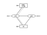
- FIG. 3 is a block diagram showing the overall configuration of a 5G communication system 210 under discussion in 3GPP.
- the radio access network is called NG-RAN (Next Generation Radio Access Network) 211 .
- the UE 202 is capable of wireless communication with an NR base station device (hereinafter referred to as "NR base station (NG-RAN NodeB: gNB)") 213, and transmits and receives signals by wireless communication.
- NR base station (NG-RAN NodeB: gNB) Next Generation Radio Access Network
- the core network is called 5G Core (5GC).
- 5GC 5G Core
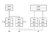
- Control protocols for UE 202 such as RRC (Radio Resource Control), user plane (hereinafter sometimes referred to as U-Plane), such as SDAP (Service Data Adaptation Protocol), PDCP (Packet Data Convergence Protocol), RLC (Radio Link Control), MAC (Medium Access Control), and PHY (Physical layer) terminate at the NR base station 213, the NG-RAN is configured by one or more NR base stations 213.
- RRC Radio Resource Control
- U-Plane user plane
- SDAP Service Data Adaptation Protocol
- PDCP Packet Data Convergence Protocol
- RLC Radio Link Control
- MAC Medium Access Control
- PHY Physical layer
- the function of the control protocol RRC (Radio Resource Control) between the UE 202 and the NR base station 213 is the same as in LTE.
- the states of the NR base station 213 and the UE 202 in RRC include RRC_IDLE, RRC_CONNECTED, and RRC_INACTIVE.
- RRC_IDLE and RRC_CONNECTED are the same as in the LTE system.
- RRC_INACTIVE maintains the connection between the 5G core and the NR base station 213, while system information (System Information: SI) is broadcast, paging, cell re-selection, mobility, etc. are performed. .
- SI System Information
- gNB 217 has access and mobility management function (AMF), session management function (SMF), or user plane function (UPF), or AMF/SMF/UPF including AMF, SMF and UPF section (hereinafter sometimes referred to as “5GC section”) 214 via an NG interface.
- AMF access and mobility management function
- SMF session management function
- UPF user plane function
- AMF/SMF/UPF including AMF, SMF and UPF section hereinafter sometimes referred to as “5GC section” 214 via an NG interface.
- AMF access and mobility management function
- SMF session management function
- UPF user plane function
- AMF/SMF/UPF including AMF, SMF and UPF section hereinafter sometimes referred to as “5GC section” 214 via an NG interface.
- Control information and/or user data are communicated between the gNB 217 and the 5GC unit 214 .
- the NG interface is a generic term for the N2 interface between gNB 217 and AMF, the
- the 5GC unit 214 is a host device, specifically a host node, and distributes paging signals to one or more base stations 203 and/or base stations 213 .
- the 5GC unit 214 performs mobility control in the idle state (Idle State).
- the 5GC unit 214 manages the tracking area list when the mobile terminal 202 is in the standby state, inactive state, and in the active state.
- the 5GC unit 214 initiates the paging protocol by sending a paging message to the cell belonging to the Tracking Area in which the mobile terminal 202 is registered.
- each cell is configured to be able to communicate with UE 202 .
- the gNB 217 may be divided into a central unit (hereinafter referred to as CU) 218 and a distributed unit (hereinafter referred to as DU) 219.
- CU central unit
- DU distributed unit
- One CU 218 is configured in gNB 217 .
- One or more DUs 219 are configured in gNBs 217 .
- CU 218 is connected to DU 219 by an F1 interface, and control information and/or user data are communicated between CU 218 and DU 219 .
- the 5G communication system may include the Unified Data Management (UDM) function and Policy Control Function (PCF) described in Non-Patent Document 21 (3GPP TS23.501).
- UDM and/or PCF may be included in 5GC section 214 in FIG.
- a location management function described in Non-Patent Document 32 (3GPP TS38.305) may be provided.
- the LMF may be connected to the base station via the AMF as disclosed in Non-Patent Document 33 (3GPP TS23.273).
- the non-3GPP interworking function (N3IWF) described in Non-Patent Document 21 (3GPP TS23.501) may be included.
- the N3IWF may terminate an access network (AN) with the UE in non-3GPP access with the UE.
- AN access network
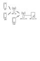
- FIG. 4 is a diagram showing the configuration of DC by eNB and gNB connected to EPC.
- solid lines indicate U-Plane connections
- dashed lines indicate C-Plane connections.
- the eNB 223-1 is the master base station and the gNB 224-2 is the secondary base station (this DC configuration is sometimes referred to as EN-DC).
- FIG. 4 shows an example in which the U-Plane connection between the MME unit 204 and the gNB 224-2 is performed via the eNB 223-1, but even if it is performed directly between the MME unit 204 and the gNB 224-2 good.
- FIG. 5 is a diagram showing the configuration of DC by gNBs connected to the NG core.
- solid lines indicate U-Plane connections
- dashed lines indicate C-Plane connections.
- gNB 224-1 is the master base station
- gNB 224-2 is the secondary base station (this DC configuration may be referred to as NR-DC).
- FIG. 5 shows an example in which the U-Plane connection between the 5GC unit 214 and the gNB224-2 is performed via the gNB224-1. good.
- FIG. 6 is a diagram showing the configuration of DC by eNB and gNB connected to the NG core.
- solid lines indicate U-Plane connections
- dashed lines indicate C-Plane connections.
- the eNB 226-1 is the master base station and the gNB 224-2 is the secondary base station (this DC configuration may be referred to as NG-EN-DC).
- FIG. 6 shows an example in which the U-Plane connection between the 5GC unit 214 and the gNB224-2 is performed via the eNB226-1. good.
- FIG. 7 is a diagram showing another configuration of DC by eNB and gNB connected to the NG core.
- solid lines indicate U-Plane connections
- dashed lines indicate C-Plane connections.
- gNB 224-1 is the master base station
- eNB 226-2 is the secondary base station (this DC configuration may be referred to as NE-DC).
- FIG. 7 shows an example in which the U-Plane connection between the 5GC unit 214 and the eNB 226-2 is performed via the gNB 224-1. good.
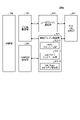
- FIG. 8 is a block diagram showing the configuration of mobile terminal 202 shown in FIG. Transmission processing of the mobile terminal 202 shown in FIG. 8 will be described.
- control data from the protocol processing unit 301 and user data from the application unit 302 are saved in the transmission data buffer unit 303 .
- the data stored in the transmission data buffer unit 303 is transferred to the encoder unit 304 and subjected to encoding processing such as error correction.
- the data encoded by the encoder section 304 is modulated by the modulation section 305 . Precoding in MIMO may be performed in modulation section 305 .
- the modulated data After being converted into a baseband signal, the modulated data is output to frequency conversion section 306 and converted into a radio transmission frequency. Thereafter, transmission signals are transmitted to base station 203 from antennas 307-1 to 307-4.
- FIG. 8 illustrates the case where the number of antennas is four, but the number of antennas is not limited to four.
- the reception processing of the mobile terminal 202 is executed as follows. Radio signals from base station 203 are received by antennas 307-1 to 307-4. The received signal is converted from a radio reception frequency to a baseband signal by frequency conversion section 306 , and demodulated by demodulation section 308 . Weight calculation and multiplication processing may be performed in the demodulator 308 . The demodulated data is passed to the decoder section 309 and subjected to decoding processing such as error correction. Of the decoded data, control data is passed to protocol processing section 301 and user data is passed to application section 302 . A series of processing of mobile terminal 202 is controlled by control unit 310 .
- the control unit 310 is connected to each of the units 301 to 309, though omitted in FIG.
- the control unit 310 is implemented by, for example, a processing circuit including a processor and memory. That is, the control unit 310 is realized by the processor executing a program describing a series of processes of the mobile terminal 202 . A program describing a series of processes of the mobile terminal 202 is stored in the memory. Examples of memory are nonvolatile or volatile semiconductor memories such as RAM (Random Access Memory), ROM (Read Only Memory), flash memory, and the like.
- the control unit 310 may be realized by a dedicated processing circuit such as FPGA (Field Programmable Gate Array), ASIC (Application Specific Integrated Circuit), DSP (Digital Signal Processor). In FIG. 8, the number of antennas used for transmission and the number of antennas used for reception by mobile terminal 202 may be the same or different.
- FIG. 9 is a block diagram showing the configuration of base station 203 shown in FIG. Transmission processing of the base station 203 shown in FIG. 9 will be described.
- EPC communication section 401 transmits and receives data between base station 203 and EPC (MME section 204, etc.).
- the 5GC communication unit 412 transmits and receives data between the base station 203 and 5GC (5GC unit 214, etc.).
- the other base station communication unit 402 transmits and receives data to and from another base station.
- EPC communication unit 401, 5GC communication unit 412, and other base station communication unit 402 exchange information with protocol processing unit 403, respectively. Control data from protocol processing section 403 , and user data and control data from EPC communication section 401 , 5GC communication section 412 , and other base station communication section 402 are saved in transmission data buffer section 404 .
- the data stored in the transmission data buffer unit 404 is passed to the encoder unit 405 and subjected to encoding processing such as error correction. There may be data that is directly output from transmission data buffer section 404 to modulation section 406 without being subjected to encoding processing.
- the encoded data is subjected to modulation processing in modulation section 406 . Precoding in MIMO may be performed in modulation section 406 .
- the modulated data is output to frequency conversion section 407 and converted into a radio transmission frequency.
- a transmission signal is then transmitted to one or more mobile terminals 202 from antennas 408-1 to 408-4.
- FIG. 9 illustrates the case where the number of antennas is four, but the number of antennas is not limited to four.
- the reception processing of the base station 203 is executed as follows. Radio signals from one or more mobile terminals 202 are received by antenna 408 . The received signal is converted from a radio reception frequency to a baseband signal by frequency conversion section 407 and demodulated by demodulation section 409 . The demodulated data is passed to the decoder section 410 and subjected to decoding processing such as error correction. Of the decoded data, control data is passed to protocol processing unit 403, 5GC communication unit 412, EPC communication unit 401, or other base station communication unit 402, and user data is passed to 5GC communication unit 412, EPC communication unit 401, or other base station communication unit. It is passed to the station communication unit 402 .
- control unit 411 A series of processes of the base station 203 are controlled by the control unit 411 . Therefore, the control unit 411 is connected to each of the units 401 to 410 and 412, though omitted in FIG. Like the control unit 310 of the mobile terminal 202 described above, the control unit 411 is realized by a processing circuit including a processor and memory, or by a dedicated processing circuit such as FPGA, ASIC, or DSP. In FIG. 9, the number of antennas used for transmission and the number of antennas used for reception by the base station 203 may be the same or different.
- FIG. 9 is a block diagram showing the configuration of the base station 203
- the base station 213 may also have the same configuration. 8 and 9, the number of antennas of mobile terminal 202 and the number of antennas of base station 203 may be the same or different.
- FIG. 10 is a block diagram showing the configuration of the MME.
- FIG. 10 shows the configuration of MME 204a included in MME section 204 shown in FIG.
- the PDN GW communication unit 501 transmits and receives data between the MME 204a and the PDN GW (Packet Data Network Gate Way).
- a base station communication unit 502 transmits and receives data via the S1 interface between the MME 204 a and the base station 203 . If the data received from the PDN GW is user data, the user data is passed from the PDN GW communication unit 501 to the base station communication unit 502 via the user plane communication unit 503 and then to one or more base stations 203 sent. When the data received from the base station 203 is user data, the user data is passed from the base station communication unit 502 to the PDN GW communication unit 501 via the user plane communication unit 503 and transmitted to the PDN GW.
- PDN GW Packet Data Network Gate Way
- control data is passed from the PDN GW communication unit 501 to the control plane control unit 505.
- control data is passed from the base station communication section 502 to the control plane control section 505 .
- the HeNBGW communication unit 504 transmits and receives data between the MME 204a and the HeNB GW (Home-eNB Gate Way). Control data received by the HeNBGW communication unit 504 from the HeNB GW is passed to the control plane control unit 505 . The HeNBGW communication unit 504 transmits control data input from the control plane control unit 505 to the HeNB GW.
- the control plane control unit 505 includes a NAS security unit 505-1, an SAE bearer control unit 505-2, an idle state (Idle State) mobility management unit 505-3, and the like, and a control plane (hereinafter referred to as C-Plane). in some cases).
- the NAS security unit 505-1 performs NAS (Non-Access Stratum) message security and the like.
- the SAE bearer control unit 505-2 manages SAE (System Architecture Evolution) bearers.
- the idle state mobility management unit 505-3 manages mobility in the standby state (idle state: LTE-IDLE state, or simply called idle), generates and controls paging signals in the standby state, Adds, deletes, updates, searches, manages the tracking area list, etc. of the tracking areas of one or more mobile terminals 202 .
- the MME 204a distributes paging signals to one or more base stations 203.
- the MME 204a also performs mobility control in the idle state.
- the MME 204a manages the tracking area list when the mobile terminal 202 is in a standby state and in an active state.
- the MME 204a initiates the paging protocol by sending a paging message to a cell belonging to the Tracking Area in which the mobile terminal 202 is registered.
- Management of the CSG, CSG ID, and whitelist of the eNB 207 connected to the MME 204a may be performed by the idle state mobility manager 505-3.
- control unit 506 is connected to each of the units 501 to 505, although omitted in FIG.
- control unit 506 is implemented by a processing circuit including a processor and memory, or by a dedicated processing circuit such as FPGA, ASIC, or DSP.
- FIG. 11 is a block diagram showing the configuration of the 5GC section.
- FIG. 11 shows the configuration of the 5GC section 214 shown in FIG. 3 described above.
- FIG. 11 shows a case where the 5GC section 214 shown in FIG. 5 includes an AMF configuration, an SMF configuration, and a UPF configuration.
- the Data Network communication unit 521 transmits and receives data between the 5GC unit 214 and the Data Network.
- the base station communication unit 522 transmits and receives data via the S1 interface between the 5GC unit 214 and the base station 203 and/or the NG interface between the 5GC unit 214 and the base station 213 .
- the user data is passed from the Data Network communication unit 521 to the base station communication unit 522 via the user plane communication unit 523, and is sent to one or more base stations 203 and/or transmitted to base station 213 .
- the user data is passed from the base station communication unit 522 to the data network communication unit 521 via the user plane communication unit 523, and transferred to the data network. sent to.
- control data When the data received from the Data Network is control data, the control data is passed from the Data Network communication section 521 to the session management section 527 via the user plane communication section 523 .
- the session manager 527 passes control data to the control plane controller 525 . If the data received from base station 203 and/or base station 213 is control data, the control data is passed from base station communication section 522 to control plane control section 525 .
- the control plane controller 525 passes control data to the session manager 527 .
- the control plane control unit 525 includes a NAS security unit 525-1, a PDU session control unit 525-2, an idle state (Idle State) mobility management unit 525-3, etc., and is a control plane (hereinafter also referred to as C-Plane). existing).
- the NAS security unit 525-1 performs NAS (Non-Access Stratum) message security and the like.
- the PDU session control unit 525-2 manages the PDU session between the mobile terminal 202 and the 5GC unit 214, and the like.
- the idle state mobility management unit 525-3 manages mobility in the standby state (idle state: RRC_IDLE state, or simply called idle), generates and controls paging signals in the standby state, Adds, deletes, updates, searches, manages the tracking area list, etc. of the tracking areas of one or more mobile terminals 202 .
- control unit 526 A series of processes of the 5GC unit 214 are controlled by the control unit 526 . Therefore, the control unit 526 is connected to each of the units 521 to 523, 525 and 527, although omitted in FIG. Like the control unit 310 of the mobile terminal 202 described above, the control unit 526 is implemented by a processing circuit including a processor and memory, or by a dedicated processing circuit such as FPGA, ASIC, or DSP.
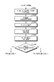
- FIG. 12 is a flowchart showing an overview from cell search to standby operation performed by a communication terminal (UE) in an LTE communication system.
- UE communication terminal
- FIG. 12 is a flowchart showing an overview from cell search to standby operation performed by a communication terminal (UE) in an LTE communication system.
- step ST601 slot timing, frame Synchronize timing.
- a combination of P-SS and S-SS is called a Synchronization Signal (SS).
- the synchronization signal (SS) is assigned a synchronization code corresponding to the PCI assigned to each cell on a one-to-one basis.
- the communication terminal synchronizes using these 504 PCIs and detects (specifies) the PCI of the synchronized cell.
- the communication terminal transmits a cell-specific reference signal (RS), which is a reference signal (RS) transmitted from the base station to each cell, for the next synchronized cell. ) and measure the RS received power (Reference Signal Received Power: RSRP).
- RS Cell-specific reference signal
- RSRP Reference Signal Received Power
- a code corresponding to PCI on a one-to-one basis is used for the reference signal (RS). It can be separated from other cells by correlating with that code.
- step ST603 the communication terminal selects the cell with the best RS reception quality, for example, the cell with the highest RS reception power, that is, the best cell, from among the one or more cells detected up to step ST602. select.
- the communication terminal receives the PBCH of the best cell and obtains BCCH, which is broadcast information.
- MIB Master Information Block
- DL downlink
- dl-bandwidth transmission bandwidth configuration
- SFN System Frame Number
- SIB1 includes information on access to the cell, information on cell selection, and scheduling information on other SIBs (SIBk; an integer of k ⁇ 2). SIB1 also includes a tracking area code (TAC).
- TAC tracking area code
- step ST606 the communication terminal compares the TAC of SIB1 received in step ST605 with the TAC portion of the tracking area identifier (TAI) in the tracking area list already held by the communication terminal.
- a tracking area list is also called a TAI list.
- TAI is identification information for identifying a tracking area, and is composed of MCC (Mobile Country Code), MNC (Mobile Network Code), and TAC (Tracking Area Code).
- MCC Mobile Country Code
- MNC Mobile Network Code
- TAC Track Area Code
- MCC Mobile Country Code
- MNC Mobile Network Code
- TAC Track Area Code
- step ST606 if the TAC received in step ST605 is the same as the TAC included in the tracking area list, the communication terminal enters standby operation in that cell.
- the communication terminal sends a TAU (Tracking Area Update) to the core network (Core Network, EPC) including the MME etc. through the cell. Request a change of tracking area to do so.
- TAU Track Area Update
- the example shown in FIG. 12 shows an example of the operation from cell search to standby in the LTE system, but in the NR system, the best beam may be selected in addition to the best cell in step ST603.
- beam information for example, a beam identifier may be obtained in step ST604.
- scheduling information of Remaining Minimum SI (RMSI) may be acquired in step ST604.
- the RMSI may be received in step ST605.
- a device constituting the core network (hereinafter sometimes referred to as “core network side device") is based on the identification number (UE-ID etc.) of the communication terminal sent from the communication terminal together with the TAU request signal. Update area list.
- the core network device transmits the updated tracking area list to the communication terminal.
- the communication terminal rewrites (updates) the TAC list held by the communication terminal based on the received tracking area list. After that, the communication terminal enters standby operation in the cell.
- cells configured by eNBs have relatively wide coverage.
- cells are configured to cover an area with relatively wide coverage of multiple cells configured by multiple eNBs.
- a cell configured by an eNB When converted to small cells, a cell configured by an eNB has a narrower coverage than the coverage of a cell configured by a conventional eNB. Therefore, as in the past, in order to cover a certain area, a large number of eNBs made into smaller cells are required compared to conventional eNBs.
- a cell with relatively large coverage such as a cell composed of conventional eNBs
- a macro cell such as a cell composed of conventional eNBs
- an eNB that constitutes a macro cell will be referred to as a “macro eNB”.
- a cell with relatively small coverage such as a cell made into a small cell
- an eNB that constitutes the small cell is referred to as a "small eNB”.
- a macro eNB may be, for example, a "Wide Area Base Station" described in Non-Patent Document 7.
- a small eNB may be, for example, a low power node, a local area node, a hotspot, or the like.
- the small eNB is a pico eNB that constitutes a pico cell, a femto eNB that constitutes a femto cell, HeNB, RRH (Remote Radio Head), RRU (Remote Radio Unit), RRE (Remote Radio Equipment) or RN (Relay Node).
- the small eNB may be a "Local Area Base Station" or a "Home Base Station" described in Non-Patent Document 7.
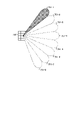
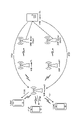
- FIG. 13 shows an example of a cell configuration in NR.
- narrow beams are formed and transmitted in different directions.
- base station 750 transmits and receives to and from mobile terminals using beam 751-1 at a given time. At other times, base station 750 transmits to and receives from mobile terminals using beam 751-2. Similarly, the base station 750 uses one or more of the beams 751-3 to 751-8 to transmit and receive with the mobile terminal. In this manner, base station 750 constitutes a wide-area cell.
- FIG. 13 shows an example in which the number of beams used by the base station 750 is eight, the number of beams may be different from eight. Also, in the example shown in FIG. 13, the number of beams used simultaneously by the base station 750 is one, but a plurality of beams may be used.
- SL Side Link
- D2D Device to Device
- V2V Vehicle to Vehicle
- the Physical sidelink broadcast channel (PSBCH) carries system and synchronization related information and is transmitted from the UE.
- the physical sidelink discovery channel (PSDCH) carries sidelink discovery messages from the UE.
- a physical sidelink control channel (PSCCH) carries control information from the UE for sidelink communication and V2X sidelink communication.
- the physical sidelink shared channel (PSSCH) carries data from the UE for sidelink communication and V2X sidelink communication.
- a physical sidelink feedback channel (PSFCH) carries HARQ feedback on the sidelink from the UE that received the PSSCH transmission to the UE that transmitted the PSSCH.
- a sidelink broadcast channel (SL-BCH: Sidelink broadcast channel) has a predetermined transport format and is mapped to a physical channel PSBCH.
- the Sidelink Discovery Channel has periodic broadcast transmissions of fixed size and predetermined format.
- SL-DCH also supports both UE autonomous resource selection and eNB scheduled resource allocation. There is a collision risk with UE automatic resource selection, and there is no collision when the UE is allocated dedicated resources by the eNB.
- SL-DCH also supports HARQ combining, but not HARQ feedback.
- SL-DCH is mapped to PSDCH, which is a physical channel.
- a sidelink shared channel supports broadcast transmission.
- SL-SCH supports both UE autonomous resource selection and eNB scheduled resource allocation. There is a collision risk with UE automatic resource selection, and there is no collision when the UE is allocated dedicated resources by the eNB.
- SL-SCH also supports HARQ combining, but not HARQ feedback.
- SL-SCH also supports dynamic link adaptation by varying transmit power, modulation and coding.
- SL-SCH is mapped to PSSCH which is a physical channel.
- a sidelink broadcast control channel (SBCCH: Sidelink Broadcast Control Channel) is a sidelink channel for reporting sidelink system information from one UE to another UE.
- SBCCH is mapped to SL-BCH, which is a transport channel.
- a sidelink traffic channel is a one-to-many sidelink traffic channel for transmitting user information from one UE to another UE.
- STCH is only used by UEs with sidelink communication capability and UEs with V2X sidelink communication capability.
- Point-to-point communication between UEs with two sidelink communication capabilities is also realized with STCH.
- STCH is mapped to SL-SCH which is a transport channel.
- a sidelink control channel is a sidelink control channel for transmitting control information from one UE to another UE.
- SCCH is mapped to SL-SCH which is a transport channel.
- V2X communication in NR is being studied based on the LTE system and the LTE-A system, the following changes and additions have been made from the LTE system and the LTE-A system.
- PC5-S signaling is implemented to establish a link for implementing SL, or PC5 communication.
- the link is implemented at the V2X layer and is also referred to as a layer 2 link.
- RRC signaling in SL communication is also called PC5 RRC signaling.
- PC5 RRC signaling it has been proposed to notify UE capabilities between UEs that perform PC5 communication, and to notify AS layer settings for performing V2X communication using PC5 communication.
- PTM Point to Multipoint
- PTP Point to Point
- a common PDCP entity may be used in PTM and PTP.
- PTM and PTP may have different legs (RLC, Logical Channel Combination).
- RLC Logical Channel Combination
- the PTM leg and the PTP leg may be used while being dynamically switched.
- a PDCP status report may be used in switching between the PTM leg and the PTP leg.
- the base station may use the PDCP status report sent from the UE to determine PTM/PTP switching for the UE.
- the base station may use the report to resend PDCP PDUs containing multicast data to the UE.
- sending a PDCP status report from the UE to the base station requires an instruction from the base station.
- the UE transmits a PDCP status report to the base station in response to an instruction such as DRB modification from the base station (see Non-Patent Documents 19 and 27). Therefore, for example, when the UE fails to receive some PDCP PDUs consisting of multicast data, the UE cannot send a PDCP status report to the base station, resulting in a missing multicast data situation in the UE. does not solve the problem.
- This embodiment discloses a method for solving such problems.
- the UE notifies the base station of information regarding the multicast reception status.
- the UE may be able to autonomously send the notification to the base station.
- a PDCP status report (see Non-Patent Document 27 (TS38.323)) may be used for the notification.
- PRACH may be used for the notification, or RRC signaling may be used.
- the base station uses the information received from the UE to switch between PTM/PTP.
- the base station may perform PTM/PTP switching without using the information.
- the base station notifies the UE of information regarding PTM/PTP switching.
- the notification may use RRC signaling, MAC signaling, or L1/L2 signaling.
- the base station may not notify the information. That is, the base station may implicitly switch between PTM/PTP.
- a UE may be able to receive PTM and PTP simultaneously. This enables, for example, rapid PTM/PTP switching in a communication system.
- a PDCP status report is used to notify information about the multicast reception status from the UE to the base station.
- the UE may autonomously send PDCP status reports.
- the UE may perform autonomous PDCP status report transmission in multicast.
- the UE may determine whether it is multicast or not.
- the UE may use the Logical Channel Identifier, the QoS Flow Identifier, or the Bearer Identifier for the determination.
- a bearer identifier As an example of determination using a bearer identifier, a multicast bearer identifier (MRB-ID) may be used.
- MMB-ID multicast bearer identifier
- the following (1) to (5) are disclosed as conditions for the UE to transmit a PDCP status report.
- the UE periodically transmits a PDCP status report to the base station.
- the base station may use the periodic reports to keep track of the multicast data reception status at the UEs. This enables, for example, the base station to continuously monitor the reception status of the UE, thereby enabling stable multicast communication.
- the period in (1) above may be predetermined by the standard, or may be determined by the base station and notified to the UE.
- the base station may perform the notification using RRC signaling, for example, RRC reconfiguration (RRCReconfiguration).
- RRC signaling may be, for example, RRC signaling used for setting up multicast. This allows, for example, signaling from the base station to be reduced.
- MAC signaling may be used, or L1/L2 signaling may be used. This enables, for example, rapid notification from the base station to the UE.
- the AMF may determine the period. AMF may notify the UE of the period. AMF may notify the period using, for example, NAS signaling. This allows, for example, the AMF to inform the UE of a lot of information.
- the UE may transmit the PDCP status report triggered by the expiration of the timer used in the PDCP layer.
- the timer may be, for example, a timer used for reordering (t-reordering described in Non-Patent Document 27).
- the base station may perform PTM/PTP switching, retransmit PDCP PDUs, or perform both of the above. This allows for example a fast retransmission from the base station after a PDCP layer reception loss at the UE.
- a timer may be newly provided for PDCP status report transmission.
- the timer may be started, for example, when PDCP PDUs arrive out of order.
- the timer value may be shorter than t-reordering, for example.
- the UE may send a PDCP status report to the base station upon expiration of a timer for PDCP status report transmission.
- the base station can send missing PDCP PDUs to the UE before t-reordering expires, and as a result, the UE can transfer the reordered multicast data to the upper layer.
- the number of missing PDCP PDUs may be used, or the number of missing PDCP SDUs (Service Data Units) may be used.
- the UE may transmit a PDCP status report to the base station when the number of missing PDCP PDUs is greater than or equal to a predetermined value.
- the number of consecutive missing points may be used.
- the aforementioned PDCP PDU may be, for example, a PDCP PDU related to multicast.
- the base station may use the report to perform PTM/PTP switching, retransmit PDCP PDUs, or both. This enables, for example, batch retransmission of missing multicast data from the base station to the UE, and as a result, efficient multicast retransmission becomes possible.
- the missing rate of PDCP PDUs may be used.
- the UE may, for example, calculate the PDCP PDU missing rate in a PDCP SN (Sequence Number) within a predetermined range, or in a COUNT value within a predetermined range (see Non-Patent Document 27 (TS38.323))) PDCP SDU missing rate may be calculated.
- the UE may send a PDCP status report to the base station if the missing rate is greater than or equal to a predetermined value.
- the base station may use the report to perform PTM/PTP switching, retransmit PDCP PDUs, or both. This allows, for example, the base station to quickly resend missing multicast data to the UE, thereby ensuring multicast reliability.
- the UE may transmit a PDCP status report when the RLC status PDU (see Non-Patent Document 28 (TS38.322)) transmission conditions are met.
- the RLC layer of the UE may notify the PDCP layer that the RLC status PDU transmission conditions have been met, and may instruct the notification of the PDCP status report to the base station.
- a UE may send both RLC status PDUs and PDCP status reports.
- the UE may send PDCP status reports instead of sending RLC status PDUs.
- the base station may use the report to perform PTM/PTP switching, retransmit PDCP PDUs, or both. This allows, for example, the UE to quickly send a PDCP status report to the base station, resulting in fast retransmission from the base station to the UE.
- the UE may transmit the PDCP status report triggered by the expiration of the timer used in the RLC layer.
- the timer may be, for example, a timer used for reassembly in the RLC layer (t-reassembly described in Non-Patent Document 28).
- the UE's RLC layer may notify the PDCP layer of the expiration of the timer or may instruct the PDCP status report to be sent to the base station.
- the base station may use the report to perform PTM/PTP switching, retransmit PDCP PDUs, or both. This allows for example a fast retransmission from the base station after a PDCP layer reception loss at the UE.
- a new timer may be provided in (3) above.
- the timer may be triggered, for example, by RLC PDUs arriving out of order.
- the timer value may be, for example, shorter than the t-reassembly above.
- the UE may send a PDCP status report to the base station upon expiration of the timer.
- the base station can send missing PDCP PDUs to the UE before t-reassembly expires, and as a result, the UE can transfer the reassembled multicast data to the upper layer.
- the number of missing RLC PDUs may be used. For example, when the number of missing RLC PDUs is greater than or equal to a predetermined value, the UE may transmit a PDCP status report to the base station. As another example, the number of continuous omissions may be used instead of the number of omissions described above.
- the RLC PDU may be, for example, an RLC PDU related to multicast.
- the base station may use the report to perform PTM/PTP switching, retransmit PDCP PDUs, or both. This enables, for example, batch retransmission of missing multicast data from the base station to the UE, and as a result, efficient multicast retransmission becomes possible.
- the RLC PDU missing rate may be used.
- the UE may, for example, calculate the RLC PDU missing rate for RLC SNs (Sequence Numbers) within a predetermined range.
- the UE may send a PDCP status report to the base station if the missing rate is greater than or equal to a predetermined value.
- the base station may use the report to perform PTM/PTP switching, retransmit PDCP PDUs, or both. This allows, for example, the base station to quickly resend missing multicast data to the UE, thereby ensuring multicast reliability.
- the RLC entity used for condition determination in (3) above may be an RLC-AM (Acknowledged Mode) entity. This makes it possible, for example, to avoid complexity in the communication system.
- the RLC entity may be an RLC-UM (Unacknowledged Mode) entity. As a result, for example, multicast reliability can be ensured with a small amount of processing.
- the RLC entity used for condition determination in (3) above may be the RLC entity used for PTM communication. This makes it possible, for example, to quickly switch from PTM to PTP.
- the RLC entity may be an RLC entity used for PTP communication. This makes it possible, for example, to quickly switch from PTP to PTM.
- the RLC entity may be both an RLC entity used for PTM communication and an RLC entity used for PTP communication. This makes it possible, for example, to quickly switch from PTM to PTP and from PTP to PTM.
- the RLC entity used for condition determination in (3) above may be the RLC entity of the active communication path. This allows, for example, a fast PDCP status report transmission from the UE to the base station. As another example, the RLC entity may be an inactive RLC entity. This allows, for example, the UE to request the base station to retransmit data waiting for retransmission in an inactive RLC entity, thereby ensuring reliability.
- the base station may configure the leg for the UE.
- the configuration may include information about the type of leg (eg, PTM leg, PTP leg), and may include information about the default operating state (eg, active, deactivated).
- the configuration may be done using RRC signaling, for example.
- the base station may send the UE a notification regarding the operation (activation) and/or deactivation (deactivation) of the leg.
- the notification may include information identifying the leg of the UE, information regarding leg operation and/or deactivation, or a combination of both.
- the notification may include information regarding which leg to operate.
- the UE may use the notification to activate or deactivate the leg.
- the UE may use information about which leg to operate to activate that leg or deactivate other legs.
- the UE may use information about which leg to operate to initiate operation of that leg while operating other legs.
- the UE may deactivate the leg using information about the leg to deactivate.
- the UE may activate or deactivate other legs using the information about the deactivated leg.
- the base station may make the notification using RRC signaling, MAC signaling, or L1/L2 signaling. This allows, for example, rapid switching of legs.
- the UE may transmit a PDCP status report to the base station when the number of HARQ retransmissions in the UE exceeds a predetermined number or is greater than a predetermined number.
- the predetermined number of times may be one time, or may be multiple times.
- the HARQ layer of the UE may notify the PDCP layer that HARQ retransmissions have exceeded a predetermined number of times or greater than a predetermined number of times, and may instruct the transmission of a PDCP status report.
- the base station may use the report to perform PTM/PTP switching, retransmit PDCP PDUs, or both. This enables, for example, batch retransmission of missing multicast data from the base station to the UE, and as a result, efficient multicast retransmission becomes possible.
- the UE sends a PDCP status report to the base station when the number of HARQ retransmissions in the UE exceeds a predetermined number of times or is greater than a predetermined number of times within a predetermined period of time.
- a timer may be provided that represents a predetermined period of time. This allows, for example, the base station to quickly resend missing multicast data to the UE, thereby ensuring multicast reliability.
- the UE when the number of HARQ retransmissions exceeded a predetermined number of times or more during a predetermined number of transport block transmissions, the UE sends a PDCP status report to the base station. may be sent. As a result, for example, the same effect as described above can be obtained.
- the predetermined value, range, number of times, and/or period in (1) to (4) above may be predetermined by the standard, or may be determined by the base station and notified to the UE.
- the base station may perform the notification using RRC signaling, for example, RRC reconfiguration (RRCReconfiguration).
- RRC signaling may be, for example, RRC signaling used for setting up multicast. This allows, for example, signaling from the base station to be reduced.
- MAC signaling may be used, or L1/L2 signaling may be used. This enables, for example, rapid notification from the base station to the UE.
- the UE may transmit the PDCP status report using the PTM leg. This allows, for example, the UE to quickly notify the base station of the report.
- the base station may individually allocate uplink PUCCH time and/or frequency and code sequence resources to UEs using the PTM leg.
- the resources assigned to the UE may be for SR or HARQ feedback.
- the UE may use the resource to send an SR to the base station.
- the base station may use the SR as a trigger to notify the UE of an uplink grant.
- the UE may use the uplink grant to send a PDCP status report to the base station.
- the resources individually allocated from the base station to the UE may be different for each UE. This makes it possible to prevent collisions with other UEs in uplink PUCCH transmission, for example.
- the base station may configure the resource using, for example, RRC dedicated signaling.
- the UE may perform the transmission using the PTP leg. This makes it possible, for example, to avoid complexity in the communication system. In this case, there may be no uplink RLC layer transmission on the UE's PTM leg. This makes it possible to reduce the circuit scale in the UE, for example.
- the UE may transmit PDCP status reports using the active leg. This enables, for example, the UE to quickly notify the base station.
- the UE may transmit PDCP status reports using the inactive leg.
- the UE may temporarily activate an inactive leg. This enables, for example, the UE to perform multicast reception and PDCP status report transmission in parallel, thereby making it possible to improve the efficiency of the communication system.
- the UE may deactivate the leg again after finishing the transmission. This allows, for example, the power consumption of the UE to be reduced.
- the UE may transmit the PDCP status report using a leg different from the leg used for condition determination in (1) to (4) above. This makes it possible to avoid deterioration of the communication environment occurring in the leg used for condition determination, for example, and as a result, it is possible to improve the reliability of transmission of the PDCP status report.
- the UE may include information about the number of PDCP PDU reception deficiencies, may include information about the number of continuous reception deficiencies of PDCP PCUs, and may include information about the timing at which the continuous reception deficiencies occur. It may be included, or information on the reception loss rate of PDCP PDUs may be included. This enables, for example, the base station to quickly grasp the information.
- the UE may include a multicast PTM/PTP switching request in the PDCP status report.
- the request may include information indicating the presence or absence of leg switching, may include information about the leg to be activated, may include information about the leg to be stopped, or may include the above-mentioned plurality of Combinations may also be included.
- the base station may or may not perform multicast PTM/PTP switching using the information. As a result, for example, the base station can quickly perform PTM/PTP switching, and as a result, reliability of multicast communication can be improved.
- the UE may notify the PDCP status report including information identifying multicast (eg, multicast identifier, logical channel identifier related to multicast, identifier of radio bearer used for multicast, eg, MRB-ID).
- information identifying multicast eg, multicast identifier, logical channel identifier related to multicast, identifier of radio bearer used for multicast, eg, MRB-ID. This allows, for example, a base station to quickly identify multicasts.
- a predetermined range may be provided for logical channel identifiers for multicast, for example, logical channel identifiers assigned to PTM legs.
- the range may differ from the range of assignable logical channel identifiers for dedicated channels. As a result, for example, in a UE that receives multicast, it is possible to prevent the logical channel identifier assigned to the PTM leg from being duplicated with the logical channel identifiers of other dedicated channels.
- a RACH may be provided for notification of the information.
- the PRACH preamble in the RACH may be different from the PRACH preamble used for connection initiation with the base station and the PRACH preamble used for system information request.
- a predetermined range may be provided as a PRACH preamble for notification of information on multicast reception status from the UE to the base station.
- the base station may use the PRACH preamble from the UE to determine the RACH type. This enables, for example, the base station to quickly determine the type of RACH.
- the base station may individually allocate the PRACH preamble to the UE.
- the assignment from the base station to the UE may, for example, be made from within the predetermined ranges mentioned above.
- the assignment from the base station to the UE may be done using RRC signaling, for example.
- the UE may use the preamble to transmit the PRACH to the base station. This makes it possible, for example, to prevent PRACH collisions between the UE and other UEs, and as a result, the UE can notify the information quickly.
- the conditions for the UE to transmit the RACH for this notification may be the same as the conditions for transmitting the PDCP status report.
- an effect similar to that of transmitting a PDCP status report can be obtained.
- the reception quality from the base station at the UE may be below or below a predetermined value.
- the UE may use the SS block, CSI-RS, PDCCH related to multicast, or multicast data to measure reception quality.
- the UE may use SINR (Signal to Interference plus Noise Ratio), SNR (Signal to Noise Ratio), or BLER (Block Error Rate) as the reception quality, BER (Bit Error Rate) (or BER conversion value) may be used, RSRP (Reference Signal Received Power), or RSRQ (Reference Signal Received Quality) may be used.
- the predetermined value may be defined in advance by a standard, or may be determined by the base station and notified or notified to the UE.
- the base station may perform multicast PTM/PTP switching, or may retransmit multicast.
- the UE can quickly notify the base station of the deterioration of reception quality, and as a result, can quickly ensure the reliability of multicast.
- the UE may include information about the multicast retransmission request, information about the multicast data to be retransmitted, or information identifying the multicast. Information similar to the PDCP status report described above may be included.
- the base station may use the information to identify multicast data that needs to be retransmitted. This allows, for example, the base station to quickly perform multicast retransmissions.
- the UE may include this information in Msg3 in random access processing and transmit it to the base station.
- the random access process may be, for example, a random access process performed in four steps. This allows, for example, the UE to send more information to the base station.
- the UE may include this information in MsgA in random access processing and transmit it to the base station.
- the random access process may be, for example, a random access process performed in two steps. This enables, for example, the UE to quickly notify the base station of the information.
- the base station may notify the UE of the PTP/PTM switching instruction by including it in Msg4 or MsgB. This makes it possible, for example, to reduce the amount of signaling between the base station and the UE.
- Msg4 or MsgB may not be transmitted from the base station to the UE on the RACH for this notification. This allows, for example, the RACH procedure for the notification to be completed quickly.
- the UE may notify the base station of the information using RRC signaling. This allows, for example, the UE to notify the base station of a lot of information.
- RRC signaling existing signaling, for example, signaling used for measurement reporting described in Non-Patent Document 19 (TS38.331) may be used. As another example, new signaling may be provided.
- the conditions for the UE to transmit the RRC signaling may be the same as the conditions for transmitting the PDCP status report described above. By this means, for example, an effect similar to that of transmitting a PDCP status report can be obtained.
- condition for transmitting the RACH may be the same as the condition for transmitting the RACH described above. As a result, for example, an effect similar to that of transmitting the RACH can be obtained.
- condition may be an event that triggers measurement (see Non-Patent Document 19 (TS38.331)).
- An existing event may be used as the event. This allows, for example, to avoid design complexity in communication systems.
- a new event may be set up.
- the new event may be, for example, the above-described occurrence of a condition for transmitting a PDCP status report, may be the same as the above-described condition for transmitting a RACH, or the above-described (1) to ( Condition 5) may occur.
- the new event may be used as the event that triggers the measurement.
- the base station may set a measurement event triggered by this event to the UE.
- the setting from the base station to the UE may be performed using measurement request signaling or may be performed using multicast setting signaling, for example.
- the UE may make a measurement report to the base station with the occurrence of the event as a trigger. This enables, for example, flexible condition setting.
- the UE may include information about the multicast retransmission request, information about the multicast data to be resent, or information identifying the multicast in the RRC signaling.
- the information may include, for example, information about the radio bearer used for transmission of the multicast data, information about the logical channel, or information about the QoS flow of the multicast data.
- information on PDCP PDUs related to retransmission may be included, information on RLC PDUs related to retransmission may be included, or information combining a plurality of the above may be included.
- the base station may use the information to identify multicast data that needs to be retransmitted. This allows, for example, the base station to quickly perform multicast retransmissions.
- the signaling disclosed above may be used in combination. Which signaling is used may be switched.
- the type of RLC entity used for multicast transmission/reception may be used to switch the signaling to be used.
- a PDCP status report may be used when using RLC-AM
- a RACH may be used when using RLC-UM. This can, for example, allow greater flexibility in the communication system and avoid complexity in the design of the communication system.
- the base station decides to switch between PTM/PTP.
- the base station may make this decision using the information about the multicast reception status received from the UE, or may make the decision without using this information.
- the base station may autonomously decide to switch.
- the base station may use HARQ-NACK from the UE (eg, triggered by receiving HARQ-NACK from the UE a predetermined number of times or more), or use the PTP leg.
- the switching may be determined using the information of the PDCP SN sent to the UE that receives the PDCP SN and the information of the PDCP SN sent to the other UE in the PTM (for example, triggered by the fact that the difference between the PDCP SNs of the two disappears) . This allows the base station, for example, to select the optimum leg according to the communication environment with the UE, thereby improving efficiency in the communication system.
- PTM/PTP switching is performed between the base station and the UE.
- the base station may request the UE to switch PTM/PTP.
- the request from the base station to the UE may be made using RRC signaling, MAC signaling or L1/L2 signaling.
- the UE uses this signaling to switch between PTM/PTP legs for receiving operations. This makes it possible, for example, to reduce power consumption in the UE.
- the base station may send the request using the leg currently used for multicast transmission to the UE. This allows, for example, the base station to quickly notify the UE of the request.
- the request may include information about the UE switching legs (eg, C-RNTI: Cell Radio Network Temporary Identifier). This makes it possible, for example, to easily identify the UE that should switch legs even if the request is sent on the PTM leg.
- the request may include information about the multicast switching leg (eg, identifier of the multicast, information about the bearer used for transmitting the multicast, information about the logical channel used for transmitting the multicast). This allows, for example, the UE to quickly identify multicasts for leg switching.
- the request may include information about the leg switching destination, information about the leg switching source, or information identifying the leg switching (e.g., PTM to PTP switching, PTP to PTM) may be included. This allows, for example, the UE to quickly identify the leg after switching.
- Switching from the PTP leg to the PTM leg may be similar to the above, e.g., the UE may send a PDCP status report to the base station, the RACH may be used, RRC signaling, For example, a measurement report may be sent.
- RLC status PDU may be sent from the UE to the base station, MAC signaling may be sent, and L1/L2 signaling may be sent.
- the base station may decide to switch from the PTP leg to the PTM leg. For example, the base station may decide to switch using the above notification from the UE, or the base station may autonomously decide. As an example of determination in the base station, it may be that t-reordering expiration in the UE does not occur for a predetermined period of time, or the PDCP SN sent to the UE receiving using the PTP leg and the PDCP sent to the other UE using the PTM If there is no SN difference, it may be set. As a result, for example, the base station can quickly determine the switching and improve communication efficiency in multicast.
- FIG. 14 is a sequence diagram showing the operation of switching from the PTM leg to the PTP leg and from the PTP leg to the PTM leg in multicast transmission from the base station to the UE.
- FIG. 14 shows an example in which the UE notifies the status of multicast reception using a PDCP status report.
- FIG. 14 shows an example in which the notification is triggered by the expiration of the t-reordering timer.
- the base station instructs the UE to set multicast.
- the base station may make this notification using, for example, RRC reconfiguration (see Non-Patent Document 19 (TS38.331)).
- the indication from the base station to the UE may include target multicast information (e.g., multicast identifier, identifier of radio bearer to use for multicast transmission), and may include information about PTM leg and/or PTP leg configuration.
- Information may be included, information on notification from the UE to the base station, e.g., the method of the notification (e.g., PDCP status report, RACH, RRC signaling), may be included, conditions for the notification Information (eg, information on (1) to (5) above) may be included, and information on configuration of uplink transmission from the UE may be included.
- the information on PTM leg and/or PTP leg configuration may include information on logical channels (e.g., logical channel identifier), may include information on RLC layer configuration, or may include information on MAC layer configuration.
- Information may be included, and information about the PHY layer may be included.
- the information about the uplink transmission configuration from the UE may include, for example, information about the time and/or frequency of the uplink PUCCH and the code sequence resource. The UE may use the notification to configure multicast reception.
- step ST1417 shown in FIG. 14 the UE notifies that multicast setting has been completed.
- the UE may do this notification using, for example, RRC Reconfiguration Complete (see Non-Patent Document 19 (TS38.331)).
- the base station requests multicast distribution from AMF.
- the request may include information identifying the UE, and may include information identifying the multicast.
- the AMF requests multicast delivery to the multicast/broadcast SMF (MB-SMF) (see Non-Patent Document 24 (see TR23.757)).
- MB-SMF multicast/broadcast SMF
- session information related to multicast distribution is modified (Modification) between MB-SMF and multicast/broadcast UPF (MB-UPF) (see Non-Patent Document 24 (TR23.757)).
- MB-SMF notifies AMF of a response to the multicast distribution request.
- the AMF notifies the base station of the response to the multicast distribution request.
- step ST1429 shown in FIG. 14 the base station notifies the AMF of a response to the change of session information related to multicast distribution.
- AMF notifies SMF of a response to the change of session information.
- the processing of Nsmf_PDUSession_Update may be used.
- the SMF uses the notification to determine that UPF may not be used, and notifies the AMF.
- the notification may include the session management context.
- the MB-UPF transmits multicast data to the base station.
- the base station transmits multicast data to UEs.
- Multicast data transmission in step ST1435 is performed using the PTM leg.
- step ST1437 shown in FIG. 14 the UE checks whether the t-reordering timer has expired. If the timer has not expired, continue to receive multicast data. When the timer expires, the process of step ST1439 is performed.
- step ST1439 shown in FIG. 14 the UE transmits a PDCP status report to the base station.
- the report may contain information about missing PDCP PDUs.
- the base station may use step ST1439 to determine whether to switch PTM/PTP. In the example shown in FIG. 14, the base station determines to switch from the PTM leg to the PTP leg for multicast communication to the UE.
- step ST1441 shown in FIG. 14 PTM/PTP switching is performed between the base station and the UE. That is, the base station switches the multicast transmission leg for the UE from the PTM leg to the PTP leg.
- the base station may or may not notify the UE of the switching.
- the base station may use RRC signaling, MAC signaling, or L1/L2 signaling for the notification.
- the base station may make this notification to the UE using the active leg, the PTM leg in the example of FIG.
- the notification using the PTM leg may include information about the UE, information specifying the multicast, and information indicating switching from the PTM leg to the PTP leg. may be
- the UE may use the notification as a trigger to switch the leg used for multicast reception from the PTM leg to the PTP leg.
- step ST1442 shown in FIG. 14 the base station retransmits the multicast data to the UE.
- the retransmission from the base station to the UE is done using the PTP leg.
- the data to be resent may be, for example, the missing PDCP PDU indicated by the information included in the PDCP status report transmitted in step ST1439.
- the MB-UPF transmits multicast data to the base station.
- the base station transmits multicast data to UEs. Multicast data transmission in step ST1445 is performed using the PTP leg.
- the base station determines to switch the multicast transmission leg for the UE from the PTP leg to the PTM leg.
- the base station for example, the PDCP PDU that is transmitted to the UE using the PTP leg is the same or earlier data than the PDCP PDU that is transmitted to the other UE using the PTM leg, i.e. , the PDCP SN (Sequence Number) of the PDCP PDU to be transmitted using the PTP leg may be greater than or equal to the PDCP SN of the PDCP PDU to be transmitted using the PTM leg.
- the base station may or may not notify the UE of the switching.
- the notification from the base station to the UE may be the same as in step ST1441.
- the UE may use the notification as a trigger to switch the leg used for multicast reception from the PTP leg to the PTM leg.
- the MB-UPF transmits multicast data to the base station.
- the base station transmits multicast data to UEs.
- Multicast data transmission in step ST1451 is performed using the PTM leg.
- FIG. 14 shows an example of transmitting a PDCP status report triggered by the expiration of the t-reordering timer
- the UE may transmit a PDCP status report triggered by the expiration of another timer.
- a new timer may be provided.
- the timer may be, for example, a shorter value than the t-reordering timer.
- the base station can transmit PDCP PDUs related to multicast data to the UE before t-reordering expires, and as a result, the UE can transfer the multicast data after reordering to the upper layer.
- FIG. 14 shows an example of sending a PDCP status report triggered by the expiration of the t-reordering timer, it may be triggered by other conditions. For example, a condition regarding the number of missing PDCP PDUs may be used, or a condition regarding the number of missing RLC PDUs may be used. This makes it possible, for example, to quickly retransmit missing multicast data from the base station to the UE.
- FIG. 15 is a sequence diagram showing another example of the operation of switching from the PTM leg to the PTP leg and from the PTP leg to the PTM leg in multicast transmission from the base station to the UE.
- FIG. 15 shows an example in which the UE notifies the status of multicast reception using PRACH.
- FIG. 15 shows an example in which the notification is triggered by the expiration of the t-reordering timer.
- the same step numbers are assigned to the processes common to those in FIG. 14, and the common description is omitted.
- Steps ST1415 to ST1437 shown in FIG. 15 are the same as in FIG.
- the base station may include, in the signal transmitted in step ST1415, information regarding the range of the PRACH preamble used for notification of information regarding the multicast reception status, or the UE may include information regarding the PRACH preamble used for notification of information regarding the multicast reception status. May contain information.
- the UE performs the process of step ST1539 when the t-reordering timer expires in step ST1437.
- the UE transmits PRACH to the base station.
- the preamble used for the PRACH may belong to a different range than the PRACH preamble for initial access and/or the PRACH preamble for SI (System Information) request.
- a PRACH preamble set by the base station may be used for notification of information on multicast reception status.
- the base station transmits a random access response (RAR) to the UE.
- the information on the uplink grant for Msg3 may be included in the RAR transmitted in step ST1541.
- the UE transmits Msg3 signaling for random access processing to the base station.
- the signaling of Msg3 may include information about a multicast retransmission request, may include information about multicast data to be resent, may include information identifying multicast, or may include information about missing PDCP PDUs may be included, and information regarding the request for PTM/PTP switching may be included.
- the base station transmits Msg4 signaling for random access processing to the UE.
- Steps ST1441 to ST1445 shown in FIG. 15 are the same as in FIG.
- steps ST1557 to ST1563 shown in FIG. 15 the same processing as steps ST1539 to ST1545 is performed.
- Steps ST1447 to ST1451 shown in FIG. 15 are the same as in FIG.
- FIG. 15 shows an example in which the PRACH is transmitted triggered by the expiration of the t-reordering timer, it may be triggered by the expiration of another timer.
- a new timer may be provided.
- the timer may be, for example, a shorter value than the t-reordering timer.
- the base station can transmit PDCP PDUs related to multicast data to the UE before t-reordering expires, and as a result, the UE can transfer the multicast data after reordering to the upper layer.
- FIG. 15 shows an example in which the PRACH is transmitted triggered by the expiration of the t-reordering timer
- other conditions may be used as a trigger.
- a condition regarding the number of missing PDCP PDUs may be used, or a condition regarding the number of missing RLC PDUs may be used. This makes it possible, for example, to quickly retransmit missing multicast data from the base station to the UE.
- steps ST1545 and ST1441 shown in FIG. 15 an example of performing Msg4 transmission from the base station to the UE and switching from the PTM leg to the PTP leg in different steps was shown, but they may be performed in the same step.
- the base station may decide to switch from the PTM leg to the PTP leg with the transmission of Msg3 in step ST1543 as a trigger, and may notify the UE including information on the switching in Msg4 in step ST1545.
- the same may be applied to steps ST1561, ST1563, and ST1447. This makes it possible, for example, to reduce the amount of signaling between the base station and the UE.
- steps ST1539 and ST1543 may be integrated as MsgA
- steps ST1541 and ST1545 may be integrated as MsgB.
- the base station may autonomously switch from the PTP leg to the PTM leg.
- the base station is triggered by the PDCP SN value of the PDCP PDU transmitted using the PTP leg being greater than or equal to the PDCP SN value of the PDCP PDU transmitted using the PTM leg to another UE. , a switch from the PTP leg to the PTM leg. This makes it possible to quickly switch from the PTP leg to the PTM leg and reduce the signaling between the base station and the UE.
- the case of using the multicast PTM leg and the PTP leg by switching is shown, but the PTM leg and the PTP leg may be used simultaneously.
- multicast retransmissions may be sent and received using the PTP leg. This can, for example, improve the efficiency of multicasting in a communication system.
- the base station may not send the request to the UE.
- a UE may be able to receive a multicast using either leg. This enables, for example, rapid PTM/PTP switching between the base station and the UE.
- the UE determines which leg of PTM/PTP to use using the PDCCH reception result related to the multicast data. For example, if the PDCCH is decodable using the multicast RNTI, the UE may receive the multicast data using the PTM leg, or if the PDCCH is decodable using the C-RNTI. , the UE may receive the multicast data using the PTP leg.
- the base station may transmit only multicast data for retransmission using the PTP leg. This allows, for example, increased efficiency in multicast transmissions.
- the base station may transmit using the PTP leg to UEs with poor propagation environment. This makes it possible, for example, to prevent the output of radio waves of excessive intensity to other UEs.
- FIG. 16 is a sequence diagram showing operations in which the PTM leg and the PTP leg are used simultaneously in multicast transmission from the base station to the UE.
- FIG. 16 shows an example in which the UE notifies the status of multicast reception using a PDCP status report.
- FIG. 16 shows an example in which the notification is triggered by the expiration of the t-reordering timer.
- the same step numbers are assigned to the processes common to those in FIG. 14, and the common description is omitted.
- Steps ST1415 to ST1433 shown in FIG. 16 are the same as in FIG.
- step ST1435 shown in FIG. 16 the base station transmits multicast data to UEs.
- the transmission is done using the PTM leg.
- the UE receives the data using the PTM leg.
- the UE determines to use the PTM leg because the PDCCH related to step ST1435 can be decoded using the multicast RNTI.
- Steps ST1437 to ST1439 shown in FIG. 16 are the same as in FIG.
- step ST1442 shown in FIG. 16 the base station resends the multicast data to the UE.
- the retransmission is done using the PTP leg.
- the UE receives the data using the PTP leg.
- the UE determines to use the PTP leg because the PDCCH related to step ST1442 can be decoded using the C-RNTI.
- Step ST1443 shown in FIG. 16 is the same as in FIG.
- step ST1645 shown in FIG. 16 the base station transmits multicast data to UEs.
- the transmission is done using the PTM leg.
- the UE receives the data using the PTM leg.
- the UE determines to use the PTM leg because the PDCCH related to step ST1645 can be decoded using the multicast RNTI.
- Step ST1449 shown in FIG. 16 is the same as in FIG.
- Step ST1451 shown in FIG. 16 is the same as step ST1645.
- FIG. 16 shows an example of sending a PDCP status report triggered by the expiration of the t-reordering timer, it may be triggered by the expiration of another timer.
- a new timer may be provided.
- the timer may be, for example, a shorter value than the t-reordering timer.
- the base station can transmit PDCP PDUs related to multicast data to the UE before t-reordering expires, and as a result, the UE can transfer the multicast data after reordering to the upper layer.
- FIG. 16 shows an example of sending a PDCP status report triggered by the expiration of the t-reordering timer, it may be triggered by other conditions. For example, a condition regarding the number of missing PDCP PDUs may be used, or a condition regarding the number of missing RLC PDUs may be used. This makes it possible, for example, to quickly retransmit missing multicast data from the base station to the UE.
- RACH may be used, or RRC signaling may be used. This makes it possible, for example, to avoid complexity in the communication system.
- Different carriers may be used and different BWPs may be used in the PTM leg and the PTP leg.
- the base station may configure different carriers or different BWPs for the UE as radio resources in the PTM leg and the PTP leg. This allows, for example, a UE to quickly distinguish between PTM and PTP legs.
- the first embodiment it is possible to notify the multicast reception status from the UE to the base station, and as a result, it is possible to improve the reliability of multicast.
- Modification 1 of the first embodiment discloses an RLC entity used for multicast transmission/reception in Embodiment 1.
- FIG. 1 is an RLC entity used for multicast transmission/reception in Embodiment 1.
- both the RLC-AM entity and the RLC-UM entity may be connected to the PDCP having the PTM leg and the PTP leg.
- two RLC-UM entities and one RLC-AM entity may be connected to one PDCP.
- the two RLC-UM entities may be one for transmission and one for reception.
- two RLC-UM entities may be for the PTM leg and one RLC-AM entity for the PTP leg.
- FIG. 17 is a diagram showing configurations of PDCP entities and RLC entities used in multicast using PTM legs and/or PTP legs.
- both the base station and the UE use two RLC-UM entities for the PTM leg and one RLC-AM entity for the PTP leg.
- the transmitting entity Of the two RLC entities in the PTM leg, one is the transmitting entity and one is the receiving entity.
- Both the base station and the UE have RLC-UM transmitting and receiving entities facing each other.
- Both the base station and the UE have RLC-AM entities facing each other for the PTP leg.
- one RLC-UM entity and one RLC-AM entity may be connected to one PDCP.
- the RLC-UM entity at the UE may be the receiving RLC-UM entity.
- the RLC-UM entity at the base station may be the RLC-UM entity for transmission.
- an RLC-UM entity may be for the PTM leg and an RLC-AM entity may be for the PTP leg. This allows, for example, the memory usage required for multicasting to be reduced in base stations and UEs.
- FIG. 18 is a diagram showing another example of configurations of PDCP entities and RLC entities used in multicast using PTM legs and/or PTP legs.
- both the base station and the UE use one RLC-UM entity for the PTM leg and one RLC-AM entity for the PTP leg.
- an RLC-UM entity is used for transmission.
- a receiving RLC-UM entity is used in the UE's PTM leg.
- a transmitting RLC-UM entity in the base station and a receiving RLC-UM entity in the UE face each other.
- Both the base station and the UE have RLC-AM entities facing each other for the PTP leg.
- three RLC-UM entities may be connected to one PDCP.
- the RLC-UM entity in the base station may be one for reception and two for transmission.
- one transmitting RLC-UM entity and one receiving RLC-UM entity may be for the PTP leg, or one receiving RLC-UM entity at the UE and one transmitting RLC-UM entity at the base station.
- One may be for the PTM leg. This eliminates the need for an RLC-AM entity, for example, and as a result, it is possible to reduce the amount of processing in the base station and the UE.
- FIG. 19 is a diagram showing another example of configurations of PDCP entities and RLC entities used in multicast using PTM legs and/or PTP legs.
- both the base station and the UE use one RLC-UM entity for the PTM leg and two RLC-UM entities for the PTP leg.
- an RLC-UM entity is used for transmission.
- a receiving RLC-UM entity is used in the UE's PTM leg.
- a transmitting RLC-UM entity in the base station and a receiving RLC-UM entity in the UE face each other.
- the two RLC-UM entities in the PTP leg one is a transmitting entity and one is a receiving entity.
- the transmitting and receiving entities of the RLC-UM entity are facing each other.
- the base station may notify the UE of the configuration regarding PDCP and/or RLC used for multicast.
- the configuration may include information on whether PTP legs and/or PTM legs are used, information on RLC entities in PTP legs and PTM legs, e.g. , the need for transmitting and/or receiving RLC-UM entities may be included.
- the configuration may include information on the number of bits of the PDCP SN, which will be described later.
- the UE may use the settings to configure the PDCP and/or RLC layers used for multicast reception. This allows, for example, greater flexibility in communication systems.
- the operation of PDCP in multicast may be determined by the mode of the connecting RLC entity.
- PDCP to which even one RLC-AM entity is connected may operate in the same way as PDCP in AM DRB.
- a PDCP with at least one RLC-AM entity connected in the UE may send a PDCP status report to the base station. This allows, for example, fast retransmission of multicasts from the base station to the UEs.
- PDCP to which even one RLC-UM entity is connected may operate in the same way as PDCP in UM DRB.
- a PDCP with at least one RLC-UM entity connected in the UE may not send a PDCP status report to the base station.
- the PDCP of the UE may notify information about the multicast reception status using PRACH disclosed in Embodiment 1, or may notify information about the multicast reception status using RRC signaling. good. This makes it possible to reduce the amount of processing used for PDCP in the UE, for example.
- PDCP operation in multicast it may be determined based on the type of RLC entity of the PTP leg. For example, PDCP using the RLC-AM entity for the PTP leg may operate similarly to PDCP in AM DRB. This makes it possible, for example, to improve reliability in multicast.
- the PDCP operation may be determined based on the type of RLC entity of the PTM leg. For example, PDCP using the RLC-UM entity for the PTM leg may operate similarly to PDCP in UM DRB. This makes it possible, for example, to reduce the amount of processing required for multicasting.
- the PDCP SN may be 18 bits. This makes it possible to expand the buffer capacity for reordering, for example, and as a result, it is possible to buffer reordering waiting data for a long time.
- the PDCP SN may be 12 bits.
- the PDCP header size can be reduced, and as a result, the throughput in multicast can be improved.
- the PDCP SN may be given another number of bits.
- PDCPSN may be 10 bits.
- padding in the PDCP header becomes unnecessary (see Non-Patent Document 27 (TS38.323)), and as a result, throughput in multicast can be improved.
- the number of bits of the PDCP SN may be determined by the base station and notified to the UE. This allows, for example, greater flexibility in communication systems.
- sublayers may be provided in PDCP.
- common operations in PDCP using the RLC-AM entity and PDCP using the RLC-UM entity may be provided in a common layer of the sublayers, or PDCP using the RLC-AM entity and the RLC-UM entity may be provided in a common layer.
- Individual layers of the sub-layers may be provided with different operations in the PDCP used.
- the functions provided in the common layer may be, for example, discarding duplicate PDCP PDUs, reordering, header compression, or integrity protection.
- the functionality provided in the individual layer may be, for example, the recognition of missing PDCPs or the generation of PDCP status reports.
- Different individual layers may be connected to different RLC entities in the UE and/or the base station. This makes it possible, for example, to avoid complexity in the design of the communication system.
- Modification 1 enables a flexible PDCP configuration based on the multicast configuration.
- Embodiment 2 Multicast with PTM and PTP legs may be used at the DC.
- the second embodiment discloses a solution to the above-mentioned problems.
- the communication system sets the PTM leg and the PTP leg to the same base station in DC.
- the base station may be, for example, a master base station (also called MN (Master Node)) or a secondary base station (also called SN (Secondary Node)).
- FIG. 20 is a diagram showing the multicast architecture in DC.
- the secondary base station has the SDAP layer and the PDCP layer, and the secondary base station (SN) has both the PTM leg and the PTP leg.
- the master base station may control multicast. This makes it possible to reduce the amount of processing in the secondary base station, for example.
- multicast control may be performed by the secondary base station. This makes it possible to reduce the amount of processing in the master base station, for example.
- the base station provided with the multicast PDCP layer and the base station provided with the RLC layer and below may be different.
- the multicast PDCP layer may be provided in the master base station, and the multicast RLC layer and below may be provided in the secondary base station.
- a multicast PDCP layer may be provided in the secondary base station, and layers other than the multicast RLC layer may be provided in the master base station. This can, for example, increase the flexibility of the communication system.
- FIG. 21 is a diagram showing another example of multicast architecture in DC.
- the master base station has the SDAP layer and the PDCP layer, and the secondary base station has both the PTM leg and the PTP leg.
- the master base station and MB-UPF may be connected to each other.
- a master base station may control multicast. This makes it possible to reduce the amount of processing in the secondary base station, for example.
- the PTM leg and the PTP leg may be located in different base stations.
- the PTM leg may be provided in the master base station and the PTP leg in the secondary base station, or the PTP leg may be provided in the master base station and the PTM leg may be provided in the secondary base station.
- a multicast PDCP layer may be provided in the master base station. This makes it possible, for example, to quickly perform RRC configuration from the master base station to the UE.
- FIG. 22 is a diagram showing another example of multicast architecture in DC.
- the master base station has an SDAP layer and a PDCP layer.
- a master base station has a PTM leg, and a secondary base station has a PTP leg.
- the master base station and MB-UPF may be connected to each other.
- a master base station may control multicast. This makes it possible to reduce the amount of processing in the secondary base station, for example.
- a multicast PDCP layer may be provided in the secondary base station. This makes it possible to reduce the amount of processing in the master base station, for example.
- FIG. 23 is a diagram showing another example of multicast architecture in DC.
- the secondary base station has an SDAP layer and a PDCP layer.
- a master base station has a PTM leg, and a secondary base station has a PTP leg.
- the secondary base station and MB-UPF may be connected to each other. This can, for example, reduce latency in multicast transmissions.
- a master base station may control multicast. This makes it possible to reduce the amount of processing in the secondary base station, for example.
- the base station may notify the UE of multicast bearer configuration settings.
- the base station may be, for example, a master base station.
- RRC signaling may be used for the notification.
- RRC reconfiguration signaling may be used.
- the setting may be establishment, addition, modification, switching, or deletion of a multicast bearer configuration.
- the addition of the bearer configuration may be, for example, the addition of a PTM leg and/or a PTP leg, the addition of a new bearer accompanying the addition of a new multicast channel, or the addition of a new multicast channel. It may be an addition to an existing bearer for such QoS flows.
- the change in bearer configuration may be, for example, a change in parameters related to the bearer configuration.
- Switching of the bearer configuration may be, for example, switching of a base station having a PTM/PTP leg, or switching of a base station having an SDAP layer and a PDCP layer.
- Deletion of the bearer configuration may be, for example, deletion of bearers related to multicast, deletion of PTM legs and/or PTP legs, or deletion of QoS flows related to multicast channels. .
- the signaling may include information on the type of configuration (eg, establishment, addition, change, switching, deletion), may include a combination of logical channel identifiers related to multicast, PTM/PTP Information about the type of leg may be included, a UE identifier in the PTM leg (eg, G-RNTI) may be included, or a UE identifier in the PTP leg (eg, C-RNTI) may be included.
- information on the cell group in which transmission/reception of each leg is performed for example, information indicating whether it is a master cell group or a secondary cell group may be included.
- the UE may use the information to switch multicast bearer configurations. This makes it possible, for example, to prevent misconfiguration of bearers by the UE, and as a result, it becomes possible to prevent multicast malfunction.
- the master base station may notify the secondary base station of the bearer configuration settings.
- the signaling may be, for example, Xn signaling.
- the Xn signaling may be, for example, an SN modification request (S-Node Modification Request) (see Non-Patent Document 30 (TS38.423)).
- the setting may be establishment, addition, modification, switching, or deletion of a multicast bearer configuration. As a result, for example, the secondary base station can quickly grasp the setting of the bearer configuration.
- FIG. 24 is a sequence diagram of the multicast bearer configuration setting operation.
- the master base station (MN) is equipped with a PTM leg.
- FIG. 24 shows an example in which a base station with a PTP leg switches from a master base station to a secondary base station (SN).
- SN secondary base station
- the same step numbers are assigned to the processes common to those in FIG. 14, and the common description is omitted.
- Steps ST1433 to ST1445 shown in FIG. 24 are the same as in FIG.
- step ST2447 shown in FIG. 24 the MN determines to switch the PTP leg from MN to SN.
- the conditions used for the determination may be, for example, the same as the conditions disclosed in Embodiment 1, or the switching may be determined using the notification from the UE disclosed in Embodiment 1.
- step ST2449 shown in FIG. 24 the MN notifies the SN of the switching of the route of the leg.
- the MN For this notification, for example, signaling of an SN change request (S-Node Modification Request) (see Non-Patent Document 30 (TS38.423)) may be used.
- step ST2451 SN notifies MN of a response to step ST2449. In the example shown in FIG. 24, an affirmative response to step ST2449 is notified.
- the MN notifies the UE of the PTP leg path switching.
- RRC reconfiguration signaling may be used.
- the notification may include information indicating that the route of the PTP leg is switched from the MN to the SN, and settings related to the PTP leg after switching to the SN (eg, RLC settings, MAC settings, PHY settings) may be included.
- the UE uses Step ST2455 as a trigger to reconfigure the PTP leg.
- the UE notifies the MN of the PDCP status report.
- the UE notifies the MN of the completion of RRC reconfiguration.
- the MN notifies the SN of the completion of RRC reconfiguration for the secondary base station in the UE.
- the MN notifies the SN of the sequence number status.
- step ST2467 shown in FIG. 24 multicast data is transmitted from MB-UPF to MN.
- step ST2469 the MN forwards the multicast data to the SN.
- step ST2471 the SN transmits multicast data to the UE. Multicast data transmission in step ST2471 is performed using the PTP leg.
- the leg transmitting multicast is switched from PTP to PTM.
- the switching may be performed in the same manner as the method disclosed in the first embodiment, for example.
- the MN has the same or earlier data in the PDCP PDU it sends to the UE using the PTP leg than the PDCP PDU it sends to another UE using the PTM leg, i.e.
- the switch may be determined when the PDCP SN (Sequence Number) of the PDCP PDU transmitted using the PTP leg is greater than or equal to the PDCP SN of the PDCP PDU transmitted using the PTM leg.
- the MN may notify the SN of the switch. The notification may be done using the Xn interface, for example.
- the SN may discard the multicast data accumulated in the buffer with this notification as a trigger. This makes it possible, for example, to reduce memory usage in the SN.
- the SN may inform the MN of information regarding multicast data that has been confirmed for transmission to the UE.
- the notification may contain information on the RLC SN that has already arrived, may contain information on the PDCP SN, or the NR-U sequence number disclosed in Non-Patent Document 31 (TS38.425) may include information about This allows, for example, the MN to quickly learn multicast data that has already been sent to the UE.
- the MN may notify the UE of the switch. The notification may be made by a method similar to step ST1441.
- multicast data is transmitted from MB-UPF to MN.
- the MN transmits multicast data to the UE. Multicast data transmission in step ST2477 is performed using the PTM leg.
- the base station may switch the multicast bearer configuration using the load status of its own base station, or may perform the switching using the downlink signal reception strength and/or reception quality reported by the UE. Alternatively, the switching may be performed using the reception strength and/or reception quality of the uplink signal from the UE.
- the master base station may notify the AMF of information about each cell of the secondary base station, for example, information about the coverage of each cell.
- the AMF may notify the MB-SMF of the information or request information on the multicast service area.
- the MB-SMF may notify the AMF of information regarding whether or not each cell of the secondary base station is within the multicast service area, or may notify information regarding the multicast service area.
- the AMF may use the information to determine whether each cell of the secondary base station is within multicast coverage.
- the AMF may notify the master base station of the determination result.
- the master base station may notify the secondary base station of information regarding whether multicast transmission is possible.
- the information regarding whether or not transmission is possible may be provided for each cell.
- the secondary base station may or may not perform multicast transmission using the information. This makes it possible, for example, to prevent multicast transmission outside the service area by the secondary base station.
- the determination may be made by the master base station.
- the master base station may use information about the multicast coverage area from the MB-SMF and/or coverage information in each cell of the secondary base station to make this determination.
- the master base station may notify the AMF of the determination result. This makes it possible, for example, to reduce the amount of processing in the AMF.
- multicasting becomes possible even in DC. Also, in the DC, it becomes possible to distribute the load by multicasting.
- Multicast transmission for switching between PTM/PTP may be performed in a base station with a CU/DU separation configuration.
- a PTM leg and a PTP leg may be provided in the same DU.
- FIG. 25 is a diagram showing a multicast architecture in a base station with a CU/DU split configuration.
- the same DU has a PTM leg and a PTP leg.
- the PTM leg and the PTP leg may be provided in different DUs. This allows, for example, load balancing in DUs by multicast.
- FIG. 26 is a diagram showing another example of multicast architecture in a base station with a CU/DU split configuration.
- DU#1 has a PTM leg and DU#2 has a PTP leg.
- the CU may notify the DU of information regarding multicast settings.
- the F1 interface may be used for the notification.
- the following (A) to (G) are disclosed as examples of the information.
- the above information (A) may include, for example, information indicating whether or not it is a multicast, or may include information for identifying a multicast, such as a multicast identifier.
- a DU can identify multiple multicasts.
- the information regarding (B) above may be, for example, the MRB-ID.
- the DU can identify the bearers required for multicast transmission.
- the information regarding (C) above may be, for example, 5QI (5G QoS Identifier) (see Non-Patent Document 21 (TS23.501)).
- the DU can perform optimal scheduling based on QoS.
- the information on (D) above may include information indicating whether it is a PTM leg or a PTP leg, and may include information on logical channels using the leg (eg, logical channel identifier).
- information about RLC used in the leg for example, information about the type of RLC entity, information about MAC, or information about the physical layer may be included.
- (D) above allows, for example, a DU to set up a leg for multicast transmission.
- the information regarding (E) described above may include, for example, information regarding the leg after switching.
- the DU can reduce the amount of processing in PTM/PTP switching.
- the information related to (F) above may include, for example, information about the conditions for switching from the PTM leg to the PTP leg, or information about the condition for switching from the PTP leg to the PTM leg.
- Information about the switching conditions for example, the information on the above-described (1) to (5) disclosed as the conditions for the UE to transmit the PDCP status report in Embodiment 1 may be included, or the above-described (1)
- Information regarding predetermined values, ranges, times, and/or durations in (4) may be included.
- the DU may use this information to switch between PTM/PTP legs.
- the DU can quickly switch between PTM/PTP.
- a DU may notify a CU of information on UEs that receive multicast.
- the F1 interface may be used for the notification.
- the following (a) to (e) are disclosed as examples of such information.
- the above (a) may include information about the number and/or identifiers of UEs performing multicast reception using the PTM leg.
- the CU can grasp the number of UEs using the PTM leg, and as a result, can quickly determine PTM/PTP switching.
- the above (b) may include information about the number and/or identifiers of UEs that perform multicast reception using the PTP leg.
- the CU can identify UEs using the PTP leg, and as a result, can quickly decide to switch from the PTP leg to the PTM leg.
- the above (c) may include information indicating that the PTM/PTP switching condition is satisfied, or information (eg, identifier) on the UE that has satisfied the PTM/PTP switching condition. Alternatively, information regarding the direction of the switch (eg, PTM leg to PTP leg, PTP leg to PTM leg) may be included.
- the CU can quickly grasp the UE to which PTM/PTP switching should or will be performed.
- the above (d) may include information on the number of PDCP PDUs for which acknowledgment with the UE has not been obtained, and information on the ratio of PDCP PDUs for which acknowledgment with the UE has not been obtained.
- it may contain information on the number of PDCP PDUs for which acknowledgment has not been obtained consecutively with the UE, or it may contain information on the expiration of the timer used in the PDCP layer, for example, the t-reordering timer.
- information on the number of RLC PDUs for which acknowledgment with the UE has not been obtained, or information on the ratio of RLC PDUs for which acknowledgment with the UE has not been obtained may be included However, it may contain information on the number of RLC PDUs for which acknowledgments have not been obtained consecutively with the UE, and may contain information on the expiration of timers used in the RLC layer, such as the t-reassembly timer.
- the CU may use the information to determine PTM/PTP switching. This eliminates the need for notification from the UE to the CU, for example, and as a result, the CU can quickly determine the switching.
- Multicast transmission that switches between PTM/PTP may be used in base stations in which the CU for the C-plane (CU-CP) and the CU for the U-plane (CU-UP) are separated.
- the same DU may be used for transmitting C-plane data and U-plane data.
- different DUs may be used for transmitting C-plane data and U-plane data. This makes it possible, for example, to reduce the load on the DU.
- a PTM leg and a PTP leg may be provided in the same DU. This makes it possible, for example, to avoid complexity in the control of the DU.
- PTM legs and PTP legs may be provided in different DUs. This makes it possible, for example, to reduce the load on the DU.
- FIG. 27 is a diagram showing another example of multicast architecture in a base station with a CU/DU split configuration.
- the CU of the base station is divided into CU-CP and CU-UP.
- DU#0 has a C-plane leg
- DU#1 has a U-plane PTM leg
- DU#2 has a PTP leg.
- the CU-CP may notify the CU-UP of information regarding multicast settings.
- the E1 interface may be used for the notification.
- the information may include, for example, the information (A) to (G) described above. As a result, for example, the same effect as described above can be obtained.
- the information may include information about the DU used, eg, the DU's identifier.
- the information about the DU may include, for example, information used in the PTM leg and information used in the PTP leg. This allows, for example, the CU-UP to quickly identify the DU.
- the CU-UP may notify the CU-CP of information on UEs that receive multicast.
- the E1 interface may be used for the notification.
- the information may include, for example, the information (a) to (e) described above. As a result, for example, the same effect as described above can be obtained.
- a 5G base station can support Integrated Access and Backhaul (IAB) (see Non-Patent Document 16 (TS38.300 V16.2.0)). That is, multicast may be performed using base stations that support IAB (hereinafter sometimes referred to as IAB base stations). However, how the multicast using the IAB base station is performed is not disclosed in the standards established so far, including the above Non-Patent Documents 1 to 33. Therefore, there arises a problem that the multicast using the IAB base station cannot be executed.
- IAB Integrated Access and Backhaul
- the CU and DU of the base station operating as the IAB donor are referred to as IAB donor CU and IAB donor DU, respectively.
- IAB donor DUs and/or IAB nodes perform multicast transmission to IAB nodes and/or UEs. All IAB donor DUs and IAB nodes may perform multicast transmissions.
- FIG. 28 is a connection diagram for multicast from the base stations that make up the IAB.
- an IAB donor CU and an IAB donor DU are connected by wire.
- the IAB donor DU multicasts to the IAB node and UE#3.
- Multicast transmissions from IAB donor DUs may be done using PTP or PTM.
- the IAB node performs multicast transmission to UE#1 and UE#2.
- Multicast transmissions from IAB nodes may be done using PTP or PTM.
- FIG. 29 is a protocol stack diagram in multicast transmitted from the base stations that make up the IAB to the UE.
- Each layer of L1, L2 and IP terminates between the IAB donor CU and the IAB donor DU. IP routing is done in the IAB donor DU.
- Each layer of PHY, MAC, RLC, BAP (Backhaul Adaption Protocol), and IP terminates between the IAB donor DU and the IAB node.
- Each layer of UDP (User Datagram Protocol) and GTP-U (GPRS Tunneling Protocol for User Plane) terminates between the IAB donor CU and the IAB node.
- PHY, MAC and RLC layers are terminated between the IAB node and the UE.
- PDCP and SDAP layers terminate between the IAB donor CU and the UE.
- the multicast transmission may use a PTM leg or a PTP leg.
- An IAB donor CU may decide which IAB donor DUs and/or IAB nodes to perform multicast transmissions.
- the IAB donor DU and/or the IAB node may have information regarding multicast transmission availability. The information may be included in the DU and/or the node's capabilities, for example.
- the IAB donor DU and/or IAB node may notify the IAB donor CU of the information.
- the IAB donor CU may use the information to determine which nodes should perform multicast transmissions.
- the IAB donor CU may configure the IAB donor DU and/or the IAB node for multicast transmission. This can, for example, increase the flexibility of the communication system.
- the multicast transmission may be, for example, a multicast transmission using the PTM leg. This allows avoiding the complexities of multicast in IAB, for example.
- An IAB donor DU and/or an IAB node to which no IAB node is connected under its control may perform multicast transmission.
- the multicast transmission may be, for example, a multicast using the PTP leg. This allows, for example, multicast transmissions to many UEs.
- the PTM leg and the PTP leg may pass through the same route. This makes it possible, for example, to avoid complexity in controlling multicast.
- the route through the multicast PTM leg and the route through the PTP leg may be different. This can, for example, improve the flexibility of the communication system and reduce the load on the IAB nodes.
- FIG. 30 is a diagram showing another example of connection in multicast from the base stations that make up the IAB.
- the IAB donor CU and IAB donor DU#1, and the IAB donor CU and IAB donor DU#2 are both connected by wire.
- Multicast data for PTM is transmitted from IAB donor DU#1 to IAB node#1.
- Multicast data for PTP is transmitted from IAB donor DU#2 to IAB node#2.
- Multicast data for PTM is transmitted from IAB node #1 to IAB node #3.
- Multicast data for PTP is transmitted from IAB node #2 to IAB node #3.
- IAB node #3 performs multicast transmission to UE#1 to UE#3.
- the IAB node #3 transmits multicast data for PTM to UE #1 and UE #2.
- IAB node #3 transmits multicast data for PTP to UE #3.
- Packet duplication may be used in multicast transmissions.
- packet duplication may be used in the configurations disclosed in the first to fourth embodiments.
- a UE may receive PDCP PDUs sent from both the PTM leg and the PTP leg. The UE may leave only PDCP PDUs that arrive earlier and discard PDCP PDUs with the same PDCP SN that arrive later.
- packet duplication using CA may be used.
- Different cells may be used for multicast transmission/reception using the PTM leg and multicast transmission/reception using the PTP leg. This allows, for example, frequency diversity to improve the reliability of multicast transmissions even when the same base station, DU and/or IAB node is used for the PTM and PTP legs.
- Multicast transmission using PTM and multicast transmission using PTP may be performed using different base stations, different DUs, or different IAB nodes. good. As a result, for example, a space diversity effect can be obtained in multicast, and as a result, reliability in multicast can be improved.
- a plurality of PTM legs may be provided. Multiple PTP legs may be provided.
- packet replication combined with DC and CA may be used.
- one PTM leg and one PTP leg may be provided for each of the master base station and the secondary base station, or one base station may be provided with a PTM leg and another base station may be provided with multiple PTP legs.
- UE-TX is the UE in which service data is generated. For example, if UE-TX is UE1 and UE-RX is UE2, service data is generated in UE2 and data is transmitted to UE1, then UE2 is UE-TX and UE1 is UE-
- the method of the present disclosure may be applied as RX. With this, similar effects can be obtained.
- a subframe is an example of a communication time unit in the fifth generation communication system.
- a subframe may be a scheduling unit.
- the processing described in units of subframes may be performed in units of TTIs, slots, subslots, or minislots.
- V2X Vehicle-to-everything
- SL communication used in various services such as proximity-based service, public safety, communication between wearable terminals, and communication between devices in factories.
Abstract
Description
図2は、3GPPにおいて議論されているLTE方式の通信システム200の全体的な構成を示すブロック図である。図2について説明する。無線アクセスネットワークは、E-UTRAN(Evolved Universal Terrestrial Radio Access Network)201と称される。通信端末装置である移動端末装置(以下「移動端末(User Equipment:UE)」という)202は、基地局装置(以下「基地局(E-UTRAN NodeB:eNB)」という)203と無線通信可能であり、無線通信で信号の送受信を行う。
本変形例1では、実施の形態1におけるマルチキャスト送受信に用いられるRLCエンティティについて開示する。
PTMレッグおよびPTPレッグを用いたマルチキャストが、DCにおいて用いられてもよい。
CU/DU分離構成の基地局において、PTM/PTPの切替えを行うマルチキャストの送信が行われてもよい。例えば、PTMレッグとPTPレッグが同じDUに設けられてもよい。
5G方式の基地局は、アクセス・バックホール統合(Integrated Access and Backhaul:IAB)(非特許文献16(TS38.300 V16.2.0)参照)をサポート可能である。すなわち、IABをサポートするする基地局(以下、IAB基地局と称する場合がある)を用いて、マルチキャストが行われてもよい。ところが、IAB基地局を用いたマルチキャストがどのように行われるかが、上記の非特許文献1~非特許文献33をはじめとする、これまでに策定済みの規格等では開示されていない。そのため、IAB基地局を用いたマルチキャストを実行できないという問題が生じる。
マルチキャスト送信において、パケット複製が用いられてもよい。例えば、実施の形態1~実施の形態4において開示した構成において、パケット複製が用いられてもよい。UEは、PTMレッグおよびPTPレッグの両方から送信されるPDCP PDUを受信してもよい。UEは、先に到着したPDCP PDUのみを残し、後から到着した同じPDCP SNのPDCP PDUを破棄してもよい。
Claims (14)
- New Radio Access Technologyに対応した基地局と、
前記基地局とマルチキャスト通信を行うことが可能な通信端末と、
を備え、
前記通信端末は、前記マルチキャスト通信を実行中に、データ受信状況に関する情報である受信状況情報を通信中の前記基地局へ送信し、
前記基地局は、前記受信状況情報に基づいて、前記通信端末へのデータの再送制御を行う、
ことを特徴とする通信システム。 - 前記基地局は、ポイントツーマルチポイント通信およびポイントツーポイント通信の一方または両方を使用して、データのマルチキャスト送信を行う、
ことを特徴とする請求項1に記載の通信システム。 - 前記基地局は、前記受信状況情報に基づいて、データの再送をポイントツーマルチポイント通信で行うか、ポイントツーポイント通信で行うかを決定する、
ことを特徴とする請求項1または2に記載の通信システム。 - 前記基地局は、データの初送時にポイントツーマルチポイント通信を使用し、データの再送時にポイントツーポイント通信を使用する、
ことを特徴とする請求項1から3のいずれか一つに記載の通信システム。 - 前記基地局は、データの再送が必要な状態の場合、データの再送および後続のデータの初送の両方において、ポイントツーポイント通信を使用する、
ことを特徴とする請求項1から3のいずれか一つに記載の通信システム。 - 前記基地局は、データの再送が必要な状態の場合、データの再送においてポイントツーポイント通信を使用し、後続のデータの初送においてポイントツーマルチポイント通信を使用する、
ことを特徴とする請求項1から3のいずれか一つに記載の通信システム。 - 前記通信端末は、2つの基地局に接続した状態であり、接続している2つの基地局のうちのいずれか一方がマルチキャスト送信したデータを受信する、
ことを特徴とする請求項1から6のいずれか一つに記載の通信システム。 - 前記基地局が中央ユニットと分散ユニットとで構成されている、
ことを特徴とする請求項1から7のいずれか一つに記載の通信システム。 - 前記基地局はアクセス・バックホール統合をサポートしている、
ことを特徴とする請求項1から8のいずれか一つに記載の通信システム。 - New Radio Access Technologyが適用された通信システムの基地局とマルチキャスト通信を行うことが可能な通信端末であって、
前記マルチキャスト通信を実行中に、データ受信状況に関する情報である受信状況情報を通信中の前記基地局へ送信する、
ことを特徴とする通信端末。 - 前記受信状況情報をPacket Data Convergence Protocolのステータスレポートで送信する、
ことを特徴とする請求項10に記載の通信端末。 - 前記受信状況情報を物理ランダムアクセスチャネルで送信する、
ことを特徴とする請求項10に記載の通信端末。 - 前記受信状況情報を周期的に送信する、
ことを特徴とする請求項10から12のいずれか一つに記載の通信端末。 - 予め定められた条件を満たした場合に前記受信状況情報を送信する、
ことを特徴とする請求項10から13のいずれか一つに記載の通信端末。
Priority Applications (4)
| Application Number | Priority Date | Filing Date | Title |
|---|---|---|---|
| EP22759561.8A EP4301004A1 (en) | 2021-02-25 | 2022-02-21 | Communication system and communication terminal |
| KR1020237027333A KR20230147066A (ko) | 2021-02-25 | 2022-02-21 | 통신 시스템 및 통신 단말 |
| JP2023502375A JPWO2022181525A1 (ja) | 2021-02-25 | 2022-02-21 | |
| CN202280015524.0A CN116868593A (zh) | 2021-02-25 | 2022-02-21 | 通信系统及通信终端 |
Applications Claiming Priority (2)
| Application Number | Priority Date | Filing Date | Title |
|---|---|---|---|
| JP2021-028743 | 2021-02-25 | ||
| JP2021028743 | 2021-02-25 |
Publications (1)
| Publication Number | Publication Date |
|---|---|
| WO2022181525A1 true WO2022181525A1 (ja) | 2022-09-01 |
Family
ID=83048032
Family Applications (1)
| Application Number | Title | Priority Date | Filing Date |
|---|---|---|---|
| PCT/JP2022/006883 WO2022181525A1 (ja) | 2021-02-25 | 2022-02-21 | 通信システムおよび通信端末 |
Country Status (5)
| Country | Link |
|---|---|
| EP (1) | EP4301004A1 (ja) |
| JP (1) | JPWO2022181525A1 (ja) |
| KR (1) | KR20230147066A (ja) |
| CN (1) | CN116868593A (ja) |
| WO (1) | WO2022181525A1 (ja) |
Citations (4)
| Publication number | Priority date | Publication date | Assignee | Title |
|---|---|---|---|---|
| JP2001308784A (ja) * | 2000-04-26 | 2001-11-02 | Nippon Telegr & Teleph Corp <Ntt> | マルチキャスト通信方法、並びに無線基地局装置及び無線端末局装置 |
| JP2013197909A (ja) * | 2012-03-21 | 2013-09-30 | Ricoh Co Ltd | 無線通信方法及び無線通信システム |
| US20190222970A1 (en) * | 2016-09-29 | 2019-07-18 | Huawei Technologies Co., Ltd. | Multicast Service Transmission Method and Device |
| US20200323024A1 (en) * | 2017-12-28 | 2020-10-08 | Huawei Technologies Co., Ltd. | Communication method and related product |
-
2022
- 2022-02-21 JP JP2023502375A patent/JPWO2022181525A1/ja active Pending
- 2022-02-21 WO PCT/JP2022/006883 patent/WO2022181525A1/ja active Application Filing
- 2022-02-21 CN CN202280015524.0A patent/CN116868593A/zh active Pending
- 2022-02-21 KR KR1020237027333A patent/KR20230147066A/ko unknown
- 2022-02-21 EP EP22759561.8A patent/EP4301004A1/en active Pending
Patent Citations (4)
| Publication number | Priority date | Publication date | Assignee | Title |
|---|---|---|---|---|
| JP2001308784A (ja) * | 2000-04-26 | 2001-11-02 | Nippon Telegr & Teleph Corp <Ntt> | マルチキャスト通信方法、並びに無線基地局装置及び無線端末局装置 |
| JP2013197909A (ja) * | 2012-03-21 | 2013-09-30 | Ricoh Co Ltd | 無線通信方法及び無線通信システム |
| US20190222970A1 (en) * | 2016-09-29 | 2019-07-18 | Huawei Technologies Co., Ltd. | Multicast Service Transmission Method and Device |
| US20200323024A1 (en) * | 2017-12-28 | 2020-10-08 | Huawei Technologies Co., Ltd. | Communication method and related product |
Non-Patent Citations (33)
| Title |
|---|
| "Scenarios, requirements and KPIs for 5G mobile and wireless system", ICT-317669-METIS/D1.1 |
| 3GPP R2-2009337 |
| 3GPP RP-172115 |
| 3GPP RP-201038 |
| 3GPP S1-083461 |
| 3GPP TR 23.703 |
| 3GPP TR 23.757 |
| 3GPP TR 23.799 |
| 3GPP TR 36.814 |
| 3GPP TR 36.912 |
| 3GPP TR 38.801 |
| 3GPP TR 38.802 |
| 3GPP TR 38.804 |
| 3GPP TR 38.912 |
| 3GPP TS 23.273 |
| 3GPP TS 23.287 |
| 3GPP TS 23.303 |
| 3GPP TS 23.501 |
| 3GPP TS 23.502 |
| 3GPP TS 36.300 |
| 3GPP TS 37.340 |
| 3GPP TS 38.211 |
| 3GPP TS 38.212 |
| 3GPP TS 38.213 |
| 3GPP TS 38.214 |
| 3GPP TS 38.300 |
| 3GPP TS 38.305 |
| 3GPP TS 38.321 |
| 3GPP TS 38.322 |
| 3GPP TS 38.323 |
| 3GPP TS 38.331 |
| 3GPP TS 38.423 |
| 3GPP TS 38.425 |
Also Published As
| Publication number | Publication date |
|---|---|
| JPWO2022181525A1 (ja) | 2022-09-01 |
| KR20230147066A (ko) | 2023-10-20 |
| EP4301004A1 (en) | 2024-01-03 |
| CN116868593A (zh) | 2023-10-10 |
Similar Documents
| Publication | Publication Date | Title |
|---|---|---|
| WO2020031884A1 (ja) | 通信システム、通信端末および基地局 | |
| JP2022185020A (ja) | 通信システム、セントラルユニット、およびユーザ装置 | |
| CN115996363A (zh) | 通信系统 | |
| WO2021044932A1 (ja) | 通信システム、通信端末およびネットワーク | |
| JP7420732B2 (ja) | ユーザ装置および通信システム | |
| WO2021106761A1 (ja) | 通信システム、通信端末および基地局 | |
| JP2023145753A (ja) | 通信システム、基地局および通信端末 | |
| WO2021161951A1 (ja) | 通信システムおよび通信端末 | |
| WO2022113875A1 (ja) | 通信システムおよび通信端末 | |
| WO2022030520A1 (ja) | 通信システムおよび通信端末 | |
| WO2023153336A1 (ja) | 通信システムおよび基地局 | |
| WO2022181525A1 (ja) | 通信システムおよび通信端末 | |
| US20240137826A1 (en) | Communication system and communication terminal | |
| WO2022210184A1 (ja) | 通信システムおよび基地局 | |
| WO2023054394A1 (ja) | 通信システム | |
| WO2022181526A1 (ja) | 通信システムおよび基地局 | |
| WO2023095804A1 (ja) | 通信システム | |
| WO2022255133A1 (ja) | 通信システムおよび基地局 | |
| WO2023013513A1 (ja) | 通信システム | |
| KR20240068652A (ko) | 통신 시스템 | |
| JP2024063188A (ja) | 通信システム、基地局およびユーザ装置 |
Legal Events
| Date | Code | Title | Description |
|---|---|---|---|
| 121 | Ep: the epo has been informed by wipo that ep was designated in this application |
Ref document number: 22759561 Country of ref document: EP Kind code of ref document: A1 |
|
| ENP | Entry into the national phase |
Ref document number: 2023502375 Country of ref document: JP Kind code of ref document: A |
|
| WWE | Wipo information: entry into national phase |
Ref document number: 18546668 Country of ref document: US |
|
| WWE | Wipo information: entry into national phase |
Ref document number: 202280015524.0 Country of ref document: CN |
|
| WWE | Wipo information: entry into national phase |
Ref document number: 2022759561 Country of ref document: EP |
|
| NENP | Non-entry into the national phase |
Ref country code: DE |
|
| ENP | Entry into the national phase |
Ref document number: 2022759561 Country of ref document: EP Effective date: 20230925 |