WO2022181316A1 - スピーカ用磁気回路及びスピーカ用ドライバ - Google Patents
スピーカ用磁気回路及びスピーカ用ドライバ Download PDFInfo
- Publication number
- WO2022181316A1 WO2022181316A1 PCT/JP2022/004953 JP2022004953W WO2022181316A1 WO 2022181316 A1 WO2022181316 A1 WO 2022181316A1 JP 2022004953 W JP2022004953 W JP 2022004953W WO 2022181316 A1 WO2022181316 A1 WO 2022181316A1
- Authority
- WO
- WIPO (PCT)
- Prior art keywords
- yoke
- axial direction
- magnet
- speaker
- magnetic circuit
- Prior art date
- Legal status (The legal status is an assumption and is not a legal conclusion. Google has not performed a legal analysis and makes no representation as to the accuracy of the status listed.)
- Ceased
Links
Images




Classifications
-
- H—ELECTRICITY
- H04—ELECTRIC COMMUNICATION TECHNIQUE
- H04R—LOUDSPEAKERS, MICROPHONES, GRAMOPHONE PICK-UPS OR LIKE ACOUSTIC ELECTROMECHANICAL TRANSDUCERS; ELECTRIC HEARING AIDS; PUBLIC ADDRESS SYSTEMS
- H04R9/00—Transducers of moving-coil, moving-strip, or moving-wire type
- H04R9/02—Details
- H04R9/025—Magnetic circuit
-
- H—ELECTRICITY
- H04—ELECTRIC COMMUNICATION TECHNIQUE
- H04R—LOUDSPEAKERS, MICROPHONES, GRAMOPHONE PICK-UPS OR LIKE ACOUSTIC ELECTROMECHANICAL TRANSDUCERS; ELECTRIC HEARING AIDS; PUBLIC ADDRESS SYSTEMS
- H04R7/00—Diaphragms for electromechanical transducers; Cones
- H04R7/16—Mounting or tensioning of diaphragms or cones
- H04R7/18—Mounting or tensioning of diaphragms or cones at the periphery
-
- H—ELECTRICITY
- H04—ELECTRIC COMMUNICATION TECHNIQUE
- H04R—LOUDSPEAKERS, MICROPHONES, GRAMOPHONE PICK-UPS OR LIKE ACOUSTIC ELECTROMECHANICAL TRANSDUCERS; ELECTRIC HEARING AIDS; PUBLIC ADDRESS SYSTEMS
- H04R9/00—Transducers of moving-coil, moving-strip, or moving-wire type
- H04R9/06—Loudspeakers
-
- H—ELECTRICITY
- H04—ELECTRIC COMMUNICATION TECHNIQUE
- H04R—LOUDSPEAKERS, MICROPHONES, GRAMOPHONE PICK-UPS OR LIKE ACOUSTIC ELECTROMECHANICAL TRANSDUCERS; ELECTRIC HEARING AIDS; PUBLIC ADDRESS SYSTEMS
- H04R7/00—Diaphragms for electromechanical transducers; Cones
- H04R7/02—Diaphragms for electromechanical transducers; Cones characterised by the construction
- H04R7/04—Plane diaphragms
Definitions
- the present disclosure relates to a speaker magnetic circuit and a speaker driver.
- An object of the present disclosure is to provide a speaker magnetic circuit and a speaker driver capable of securing magnetic flux density and adjusting frequency characteristics in an internal magnet type structure.
- a magnetic circuit for a speaker includes a yoke cover formed of a cylindrical magnetic body, a diaphragm attached to one end on one side in an axial direction, and a magnet disposed inside the yoke cover.
- a volume adjusting member formed of a cylindrical non-magnetic material and provided between the yoke cover and the magnet and having a first groove portion extending in the axial direction; It is provided on the other side in the axial direction and has a second groove formed at a position corresponding to the first groove, and the first groove and the second groove form a space on the one side in the axial direction inside the yoke cover.
- a yoke base forming a duct communicating with the space on the other side in the axial direction.
- the yoke cover is made of a tubular magnetic material, and the diaphragm is attached to one axial end of the yoke cover.
- a magnet is arranged inside the yoke cover, and a magnetic circuit is formed between the magnet and the yoke cover.
- a yoke base made of a magnetic material is provided on the other axial side of the magnet. Thereby, the magnetic flux density of the magnetic circuit can be improved.
- a volume adjusting member is provided between the yoke cover and the magnet.
- the volume adjusting member is made of a cylindrical non-magnetic material, and is formed with a first groove extending in the axial direction.
- a second groove is formed in the yoke base at a position corresponding to the first groove, and the first groove and the second groove constitute a duct. Since the space on one side of the magnet in the axial direction and the space on the other side in the axial direction are communicated by the duct, the air around the diaphragm can move to the outside of the yoke base through the duct when the diaphragm vibrates. , the damping of the frequency characteristics can be adjusted.
- first groove portion as used herein is not limited to a recessed portion formed by recessing a portion of the volume adjusting member, but is a concept that includes a wide range of slit-shaped portions.
- the volume adjustment member extends from one axial end of the yoke cover to the yoke base so as to fill a gap between the magnet and the yoke cover. It extends axially.
- the volume adjusting member extends to the yoke base in the axial direction, the inner volume of the yoke cover can be adjusted simply by changing the shape and size of the first groove. ) can be easily adjusted.
- the volume inside the yoke cover can be reduced by adjusting the size of the first groove portion of the volume adjusting member. As a result, it is possible to suppress the lowering of the lowest resonance frequency (F0).
- a magnetic circuit for a speaker is the first or second aspect, wherein the volume adjusting member is provided with a projection projecting from the other end in the axial direction toward the yoke base. , the yoke base is formed with an engagement recess that engages with the protrusion.
- the protrusion formed on the volume adjusting member engages with the engaging recess formed on the yoke base, so that the volume adjusting member and the yoke base are not fixed by means of adhesion or the like, and both are connected. Relative movement can be suppressed. As a result, the position of the first groove formed in the volume adjusting member and the second groove formed in the yoke base can be kept aligned.
- a magnetic circuit for a speaker is, in any one of the first to third aspects, provided with a yoke top made of a magnetic material and having a diameter smaller than that of the magnet, on one side in the axial direction of the magnet.
- the volume adjustment member includes an annular portion that is formed in an annular shape and that can support the yoke top from the radially outer side, and an annular portion that extends from the peripheral end portion of the annular portion toward the other side in the axial direction to support the magnet. and a side wall portion that can be supported from the radially outer side.
- the annular portion of the volume adjusting member supports the yoke top, and the side wall portion of the volume adjusting member supports the magnet, thereby suppressing deviation of the center axes of the yoke top and the magnet. That is, the yoke top and the magnet can be positioned by the volume adjusting member for adjusting the volume without providing a separate positioning member.
- a magnetic circuit for a speaker is, in the fourth aspect, wherein the yoke cover includes a top surface portion with which the annular portion of the volume adjustment member abuts, and an axial direction extending from the peripheral end portion of the top surface portion. and a side wall portion that extends from the outside in the radial direction to cover the volume adjusting member. A rising portion that protrudes to one side in the axial direction from the yoke top is formed.
- the volume adjustment member can be positioned by bringing the annular portion of the volume adjustment member into contact with the top surface portion of the yoke cover.
- a yoke top is inserted through the opening of the top surface, and a rising portion formed at the opening edge of the opening protrudes to one side in the axial direction from the yoke top.
- the lines of magnetic force pass obliquely from the yoke top to the rising portion, and the magnetic flux density of the magnetic circuit can be improved at the position of the coil arranged between the yoke top and the yoke cover.
- the yoke top and the yoke cover can be axially positioned by the volume adjusting member, the lines of magnetic force can flow in a desired direction.
- a speaker driver comprises the speaker magnetic circuit according to any one of the first to fifth aspects, a diaphragm provided at one axial end of the yoke cover, and a coil attached to and energized to vibrate the diaphragm.
- the speaker magnetic circuit and the speaker driver disclosed in the present disclosure it is possible to secure the magnetic flux density and adjust the frequency characteristics in the internal magnet type structure.
- FIG. 1 is an exploded perspective view of a speaker driver according to an embodiment
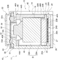
- FIG. 2 is a cross-sectional view showing the speaker driver cut along line 2-2 of FIG. 1
- FIG. 3 is a cross-sectional view showing the speaker driver cut along line 3-3 of FIG. 1
- FIG. FIG. 4 is a diagram for explaining a method of assembling the speaker driver according to the embodiment, and is a diagram showing a procedure for fitting the yoke top to the jig
- FIG. 4 is a diagram for explaining a method of assembling the speaker driver according to the embodiment, and is a diagram showing a procedure for attaching a yoke base
- FIG. 11 is an axial cross-sectional view showing a first modification of the volume adjusting member
- FIG. 11 is a cross-sectional view seen from the axial direction, showing a second modification of the volume adjusting member;
- Z shown in FIG. 1 indicates one axial direction of the speaker driver 10 .
- the Z direction side is referred to as one axial direction side.
- the side opposite to the Z direction is referred to as the other side in the axial direction.
- a speaker driver 10 (hereinafter referred to as "driver 10" as appropriate) of this embodiment includes a yoke cover 12, a volume adjustment member 14, a yoke top 16, a magnet 18, a yoke base 20, It includes a screen 22 , a metal plate 24 , a terminal 26 , a coil 28 , a diaphragm unit 30 and a lid member 32 .
- the yoke cover 12, the volume adjustment member 14, the yoke top 16, the magnet 18 and the yoke base 20 form a speaker magnetic circuit 11 (hereinafter referred to as "magnetic circuit 11" as appropriate).
- the driver 10 of the present embodiment is used, for example, in speakers mounted on earphones, headphones, and the like.
- the driver 10 of the present embodiment is, for example, a small driver with a diameter of about 4 mm.
- the yoke cover 12 is formed of a magnetic material in a cylindrical shape, and has a substantially cylindrical shape with both ends in the axial direction opened. Details of the yoke cover 12 will be described later.
- the volume adjustment member 14 is a cylindrical member arranged inside the yoke cover 12 and made of a non-magnetic material.
- the volume adjusting member 14 of the present embodiment is made of a metal member containing aluminum as a main component.
- the volume adjustment member 14 includes an annular portion 44 formed in a substantially annular shape, and a side wall portion 46 extending from the peripheral end portion of the annular portion 44 toward the other side in the axial direction (opposite side to the Z direction). consists of Details of the volume adjusting member 14 will be described later.
- the yoke top 16 and magnet 18 are arranged inside the volume adjusting member 14 .
- the magnet 18 is formed in a substantially cylindrical shape, and the magnet 18 of this embodiment is, for example, a neodymium magnet having an axial length of about 2 mm.
- a yoke top 16 is arranged on one side of the magnet 18 in the axial direction.
- the yoke top 16 is made of a magnetic material and is formed in a shape combining a truncated cone and a cylinder, and the truncated cone-shaped portion is in contact with the surface of the magnet 18 on one side in the axial direction.
- the axial length of the yoke top 16 is shorter than that of the magnet 18
- the outer diameter of the yoke top 16 is smaller than that of the magnet 18 .
- the magnet 18 is axially longer than the yoke top 16 and has a larger diameter than the yoke top 16 .
- a chamfered portion 16A is formed at one axial end of the yoke top 16 .
- a yoke base 20 is arranged on the other side of the magnet 18 in the axial direction.
- the yoke base 20 is made of a magnetic material and formed in a flat, substantially columnar shape, and the length in the axial direction of the yoke base 20 is about 0.6 mm.
- the yoke base 20 is formed to have a larger diameter than the magnet 18 and has an outer diameter approximately equal to that of the volume adjusting member 14 . Details of the yoke base 20 will be described later.
- a screen 22 is arranged on the other side of the yoke base 20 in the axial direction. As shown in FIG. 2, the screen 22 has a smaller diameter than the yoke base 20 and includes a substantially circular mesh member 22A and an annular support member 22B that supports the mesh member 22A.
- the mesh member 22A is a member in which a plurality of air vents are formed through which air communicates between the front side and the back side, and is formed of, for example, a film in which a large number of through holes are formed.
- the mesh member 22A may be formed of a member such as knitted fabric, nonwoven fabric, or urethane foam.
- a supporting member 22B of the screen 22 is formed of, for example, double-sided tape and attached to the metal plate 24 .
- the metal plate 24 is made of a non-magnetic material such as stainless steel and has a substantially flat plate shape with a diameter larger than that of the screen 22 .
- a peripheral wall portion 24A extends from the outer peripheral end portion of the metal plate 24 to one side in the axial direction.
- the peripheral wall portion 24A is fitted to the inner surface of the side wall portion 42 of the yoke cover 12 and is in contact with the yoke base 20, and the height of the peripheral wall portion 24A is greater than the thickness of the screen 22. is also higher. Therefore, a space is secured between the metal plate 24 and the yoke base 20 in which the screen 22 is arranged.
- a vent hole 24B is formed in the central portion of the metal plate 24, and the inside and outside of the driver 10 are communicated through this vent hole 24B.
- a terminal 26 is attached to the surface of the metal plate 24 on the other side in the axial direction.
- the terminal 26 is formed in a substantially disc shape, and a communication hole 26A communicating with the ventilation hole 24B of the metal plate 24 is formed in the center of the terminal 26 .
- An electrode 27 is provided on the other surface of the terminal 26 in the axial direction, and a lead wire (not shown) extending from a coil 28 is connected to the electrode 27 .
- a coil 28 and a diaphragm unit 30 are arranged on one side of the yoke cover 12 in the axial direction.
- the coil 28 is formed by winding an electric wire into a cylindrical shape, and the outer diameter of the coil 28 is smaller than that of the magnet 18 .
- the coil 28 is attached to the diaphragm unit 30 .
- the diaphragm unit 30 includes a support ring 31 and a diaphragm 33.
- the support ring 31 has a substantially annular shape and is sandwiched between the lid member 32 and the yoke cover 12 .
- a diaphragm 33 is attached to one side of the support ring 31 in the axial direction, and a coil 28 is fixed to the surface of the diaphragm 33 on the other side in the axial direction.
- the center portion of the diaphragm 33 is formed in a substantially planar shape, and an edge portion 33A that protrudes toward one side in the axial direction is formed on the outer peripheral portion of the diaphragm 33 .
- the coil 28 When the coil 28 is energized, the coil 28 moves in the axial direction, and the vibration plate 33 vibrates along with this movement.
- a lid member 32 is arranged on one side of the diaphragm unit 30 in the axial direction.
- the lid member 32 is made of a non-magnetic material such as stainless steel or aluminum and has a substantially cylindrical shape.
- An opening 32A is formed in the central portion of the lid member 32, and the sound generated by the vibration of the diaphragm 33 is output to the outside of the driver 10 through the opening 32A.
- Lid member 32 has a larger diameter on the other side in the axial direction than on the one side in the axial direction. is sandwiched between Furthermore, the other axial end of the lid member 32 is attached to the yoke cover 12 .
- the magnetic circuit 11 includes a yoke cover 12 , a volume adjusting member 14 , a yoke top 16 , a magnet 18 and a yoke base 20 .
- the yoke cover 12 includes a top surface portion 40 with which the annular portion 44 of the volume adjustment member 14 abuts, and a volume adjustment portion extending from the peripheral end portion of the top surface portion 40 to the other side in the axial direction. and a side wall portion 42 that covers the member 14 from the outside in the radial direction.
- An opening 40A is formed in the center of the top surface 40, and the tip of the yoke top 16 and the coil 28 are inserted through the opening 40A.
- the side wall portion 42 extends to the position of the terminal 26 in the axial direction, and the end surface of the side wall portion 42 on the other side in the axial direction substantially coincides with the end surface of the terminal 26 on the other side in the axial direction.
- An opening 42A is formed at the other end in the axial direction of the side wall 42, and parts such as the volume adjusting member 14, the magnet 18, the yoke base 20, the metal plate 24 and the terminal 26 are inserted through the opening 42A. It is arranged inside the cover 12 .
- the side wall portion 42 is formed with a notch portion 42B which is axially cut from one axial end portion of the yoke cover 12 to the other axial end portion thereof.
- the cutout portion 42B is formed continuously to the top surface portion 40, and a lead wire (not shown) connecting the terminal 26 and the coil 28 is passed through the cutout portion 42B.
- a rising portion 40B projecting to one side in the axial direction is formed at the opening edge of the opening portion 40A in the top surface portion 40 .
- the rising portion 40B is formed in a substantially arcuate shape when viewed from the axial direction, and is formed up to the front of the notch portion 42B formed in the side wall portion 42 . Further, as shown in FIG. 2, the rising portion 40B protrudes from the yoke top 16 toward one side in the axial direction. It has a configuration in which the lines of magnetic force are directed diagonally.
- the volume adjustment member 14 includes the annular portion 44 and the side wall portion 46 as described above.
- An opening 44A having a slightly larger diameter than the opening 40A of the yoke cover 12 is formed in the central portion of the annular portion 44, and the opening 44A communicates with the opening 40A of the yoke cover 12.
- a protrusion 44B protrudes radially inward from the inner peripheral surface of the annular portion 44, and the protrusion 44B makes the inner diameter of the other axial end of the opening 44A smaller than the inner diameter of the one axial end. It's becoming And this projection part 44B is comprised so that the yoke top 16 can be supported from the radial direction outer side.
- the side wall portion 46 extends from the peripheral end portion of the annular portion 44 to the other side in the axial direction, and is configured to be able to support the magnet 18 from the outside in the radial direction.
- the other axial end of the side wall portion 46 extends to the same position as the other axial end of the magnet 18 .
- the volume adjustment member 14 axially extends from one axial end of the yoke cover 12 to the yoke base 20 so as to fill the gap between the magnet 18 and the yoke cover 12 .
- the side wall portion 46 is formed with a first groove portion 46A extending in the axial direction.
- the first groove portion 46A is formed at a position opposite to the notch portion 42B of the yoke cover 12 around the axis. That is, the first groove portion 46A is formed at a position rotated 180 degrees around the axis with respect to the notch portion 42B of the yoke cover 12. As shown in FIG.
- the side wall portion 46 is provided with a projecting portion 46B projecting from the other axial end portion of the volume adjusting member 14 toward the yoke base 20 side.
- the projecting portion 46B is formed at a position opposite to the first groove portion 46A around the axis. That is, the projecting portion 46B is formed at a position rotated 180 degrees around the axis with respect to the first groove portion 46A.
- the yoke base 20 arranged on the other side of the magnet 18 in the axial direction is formed with a second groove portion 20A.
- the second groove portion 20A is formed on the outer peripheral surface of the yoke base 20, is formed in a circular groove shape recessed radially inward, and is formed at a position corresponding to the first groove portion 46A. That is, as shown in FIG. 3, the first groove portion 46A and the second groove portion 20A are formed continuously in the axial direction, and the first groove portion 46A and the second groove portion 20A extend in the axial direction.
- a duct portion D is constructed.
- a space on one side in the axial direction inside the yoke cover 12 and a space on the other side in the axial direction are communicated by the duct portion D. That is, when the space around the coil 28 (the space on one side in the axial direction) expands when the diaphragm 33 vibrates, air flows from the outside to the inside of the driver 10 through the communication hole 26A, the ventilation hole 24B, and the duct portion D. is introduced. At this time, the pressure is adjusted by the mesh member 22A of the screen 22. FIG. Conversely, when the space around the coil 28 is narrowed when the diaphragm 33 vibrates, the air inside the driver 10 is pushed out through the duct portion D, the ventilation hole 24B, and the communication hole 26A, and the pressure increases. adjusted.
- the yoke base 20 is formed with an engaging recess 20B that is cut out in a substantially rectangular shape.
- the engagement recess 20B is formed at a position axially opposite (180 degrees) to the second groove 20A, and is sized so that the protrusion 46B of the volume adjusting member 14 can be engaged.
- FIG. 3 when the driver 10 is assembled, the protrusion 46B of the volume adjustment member 14 is engaged by entering the engaging recess 20B of the yoke base 20, and the yoke base 20 is engaged with the volume adjustment. It is restrained from moving in the circumferential direction relative to the member 14 .
- the jig 100 includes a substantially disk-shaped base portion 100A and a cylindrical portion 100B erected at the central portion of the base portion 100A. 4 and 5, only half of the jig 100 is shown for convenience of explanation. Similarly, only half of the parts that make up the driver 10 are shown, and the cross section is shown.
- the yoke top 16 is fitted into the cylindrical portion 100B of the jig 100 with the small diameter portion facing downward. At this time, for example, the inner surface of the upper end portion of the cylindrical portion 100B is tapered to support the truncated conical portion of the yoke top 16 .
- the yoke cover 12 After fitting the yoke top 16 to the jig 100, the yoke cover 12 is fitted to the jig 100, as shown in FIG. Then, the volume adjusting member 14 is put inside the yoke cover 12 , and the annular portion 44 of the volume adjusting member 14 is brought into contact with the top surface portion 40 of the yoke cover 12 . At this time, the projection 46B of the volume adjustment member 14 is aligned with the notch 42B of the yoke cover 12 .
- the state shown in FIG. 5 is obtained. From this state, the yoke base 20 is put inside the yoke cover 12 . At this time, if the positions of the yoke base 20 engaging recess 20B and the projection 46B of the volume adjusting member 14 are not aligned, the yoke base 20 cannot be attached. Further, by aligning the engagement recess 20B of the yoke base 20 with the protrusion 46B of the volume adjustment member 14, the second groove 20A formed on the opposite side of the engagement recess 20B and the first groove 46A of the volume adjustment member 14 are matched (see FIG. 1).
- the metal plate 24 with the screen 22 attached is fitted to the yoke cover 12 as shown in FIG. As a result, the other side of the yoke cover 12 in the axial direction is closed by the metal plate 24 .
- the terminal 26 After fitting the metal plate 24 and assembling the magnetic circuit 11, the terminal 26 is adhered to the other side of the magnetic circuit 11 in the axial direction, and the coil 28 is attached to the one side of the magnetic circuit 11 in the axial direction. and a lid member 32 is attached.
- the yoke base 20 is provided on the other axial side of the magnet 18, the magnetic flux density of the magnetic circuit can be improved. That is, the magnetic flux density can be ensured even with a small driver 10 .
- a volume adjusting member 14 is provided between the yoke cover 12 and the magnet 18. As a result, it is possible to freely adjust the volume inside the driver 10 while properly maintaining the gap between the yoke cover 12 and the magnet 18 .
- the side wall portion 46 of the volume adjusting member 14 is formed with a first groove portion 46A extending in the axial direction.
- the yoke base 20 is formed with a second groove portion 20A at a position corresponding to the first groove portion 46A.
- the protrusion 46B formed on the volume adjusting member 14 is engaged with the engaging recess 20B formed on the yoke base 20.
- the second groove 20A and the engaging recess 20B have different shapes, so the yoke base 20 cannot be assembled in the wrong orientation when assembling the magnetic circuit 11.
- the volume adjusting member 14 extends to the yoke base 20 in the axial direction, the inner volume of the yoke cover 12 can be adjusted simply by changing the shape and size of the first groove. , the lowest resonant frequency (F0) can be easily adjusted.
- the volume inside the yoke cover 12 can be reduced by adjusting the first groove portion of the volume adjusting member 14 .
- the volume inside the yoke cover 12 can be finely adjusted, and the desired lowest resonance frequency (F0) can be obtained.
- the annular portion 44 of the volume adjustment member 14 supports the yoke top 16 and the side wall portion 46 of the volume adjustment member 14 supports the magnet 18 .
- the center axes of the yoke top 16 and the magnet 18 can be positioned without separately providing a positioning member.
- the rising portion 40B formed on the top surface portion 40 of the yoke cover 12 protrudes from the yoke top 16 to one side in the axial direction.
- the lines of magnetic force pass obliquely from the yoke top 16 toward the rising portion 40B, and the magnetic flux density of the magnetic circuit 11 can be improved.
- the yoke top 16 and the yoke cover 12 can be axially positioned by the volume adjusting member 14, the lines of magnetic force can flow in a desired direction.
- the yoke top 16 is positioned on the other side in the axial direction relative to the yoke cover 12, so that a wide gap can be secured between the yoke top 16 and the diaphragm 33. As shown in FIG. Thereby, it is possible to effectively suppress the diaphragm 33 from interfering with the yoke top 16 .
- the adhesive used to bond the coil 28 to the diaphragm 33 is prevented from interfering with the yoke top 16. be able to.
- the first groove portion 46A is formed only at one location of the volume adjusting member 14, but it is not limited to this.
- the modified structures shown in FIGS. 6 and 7 may be employed.
- first groove portions 46A are formed in the side wall portion 46 of the volume adjusting member 14. As shown in FIG. The first grooves 46A are formed at opposite (180 degrees) positions around the axis. That is, two first grooves 46A are formed at equal intervals in the circumferential direction.
- the yoke base 20 is formed with second grooves 20A at positions corresponding to the two first grooves 46A. Therefore, two duct portions D are formed in this modified example.
- the side wall portion 46 of the volume adjusting member 14 is formed with three first groove portions 46A.
- the first groove portion 46A is formed at a position of 120 degrees around the axis. That is, three first grooves 46A are formed at equal intervals in the circumferential direction.
- the yoke base 20 is formed with second grooves 20A at positions corresponding to the three first grooves 46A. Therefore, three duct portions D are formed in this modification.
- the number of the first groove portions 46A is increased compared to the embodiment, and the first groove portions 46A are formed at equal intervals in the circumferential direction, thereby increasing the flow of air. becomes uniform, and the vibration plate 33 can be stably vibrated.
- the driver 10 and the magnetic circuit 11 according to the embodiment have been described above, it is needless to say that they can be implemented in various forms without departing from the gist of the present disclosure.
- the chamfered portion 16A is formed on the yoke top 16, but the present invention is not limited to this. If the diaphragm 33 and the adhesive for the diaphragm 33 do not interfere with the yoke top 16 , the yoke top 16 does not need to be chamfered 16 ⁇ /b>A.
- the rising portion 40B of the yoke cover 12 protrudes further in the axial direction than the yoke top 16, and the magnetic lines of force obliquely extend from the vicinity of the chamfered portion 16A of the yoke top 16 toward the rising portion 40B.
- the magnetic lines of force are radially directed from the yoke top 16 toward the rising portion 40B.
- the length of the side wall portion 46 of the volume adjusting member 14 is set to the length that covers the entire magnet 18, but it is not limited to this.
- the side wall portion 46 may be formed axially shorter than the configuration of FIG. In this case, it is possible to prevent the other axial end portion of the side wall portion 46 from protruding further in the axial direction than the magnet 18 due to a design error or the like, thereby maintaining good contact between the magnet 18 and the yoke base 20. can do.
- the side wall portion 46 of the volume adjusting member 14 of the first groove portion 46A is formed in a substantially slit shape, but the shape is not limited to this and may be another shape.
- the first groove portion 46A may be formed by recessing the side wall portion 46 radially outward.
- the duct portion D can be configured by the first groove portion 46A and the second groove portion 20A.
Landscapes
- Engineering & Computer Science (AREA)
- Physics & Mathematics (AREA)
- Acoustics & Sound (AREA)
- Signal Processing (AREA)
- Multimedia (AREA)
- Audible-Bandwidth Dynamoelectric Transducers Other Than Pickups (AREA)
Priority Applications (3)
| Application Number | Priority Date | Filing Date | Title |
|---|---|---|---|
| CN202280016812.8A CN116888980A (zh) | 2021-02-26 | 2022-02-08 | 扬声器用磁路以及扬声器用驱动器 |
| US18/278,072 US12432500B2 (en) | 2021-02-26 | 2022-02-08 | Speaker magnetic circuit and speaker driver |
| JP2023502258A JP7743494B2 (ja) | 2021-02-26 | 2022-02-08 | スピーカ用磁気回路及びスピーカ用ドライバ |
Applications Claiming Priority (2)
| Application Number | Priority Date | Filing Date | Title |
|---|---|---|---|
| JP2021-030902 | 2021-02-26 | ||
| JP2021030902 | 2021-02-26 |
Publications (1)
| Publication Number | Publication Date |
|---|---|
| WO2022181316A1 true WO2022181316A1 (ja) | 2022-09-01 |
Family
ID=83048296
Family Applications (1)
| Application Number | Title | Priority Date | Filing Date |
|---|---|---|---|
| PCT/JP2022/004953 Ceased WO2022181316A1 (ja) | 2021-02-26 | 2022-02-08 | スピーカ用磁気回路及びスピーカ用ドライバ |
Country Status (4)
| Country | Link |
|---|---|
| US (1) | US12432500B2 (https=) |
| JP (1) | JP7743494B2 (https=) |
| CN (1) | CN116888980A (https=) |
| WO (1) | WO2022181316A1 (https=) |
Cited By (1)
| Publication number | Priority date | Publication date | Assignee | Title |
|---|---|---|---|---|
| WO2025061558A1 (en) * | 2023-09-18 | 2025-03-27 | Pss Belgium Nv | Method for use in forming a magnet unit for a loudspeaker |
Citations (4)
| Publication number | Priority date | Publication date | Assignee | Title |
|---|---|---|---|---|
| JPS4822537U (https=) * | 1971-07-20 | 1973-03-14 | ||
| JPS5038728U (https=) * | 1973-08-07 | 1975-04-21 | ||
| JPS58152089U (ja) * | 1982-04-02 | 1983-10-12 | パイオニア株式会社 | スピ−カ用振動系の制動構造 |
| JP2006217452A (ja) * | 2005-02-07 | 2006-08-17 | Matsushita Electric Ind Co Ltd | スピーカ |
Family Cites Families (6)
| Publication number | Priority date | Publication date | Assignee | Title |
|---|---|---|---|---|
| JPS57204795U (https=) * | 1981-06-23 | 1982-12-27 | ||
| JP2005203974A (ja) * | 2004-01-14 | 2005-07-28 | Pioneer Electronic Corp | ツボ型ヨーク、スピーカ装置及びツボ型ヨークの製造方法 |
| US20060188120A1 (en) * | 2005-02-23 | 2006-08-24 | Michael Fisher | Multiple active coil speaker |
| JP4896255B2 (ja) | 2010-08-06 | 2012-03-14 | フォスター電機株式会社 | マイクロスピーカ用磁気回路およびそれを用いたマイクロスピーカ |
| WO2019053714A1 (en) * | 2017-09-17 | 2019-03-21 | Mordechai Oren | DUAL PROFILE DRIVE WITH LOW PROFILE |
| JP7202249B2 (ja) | 2019-04-24 | 2023-01-11 | フォスター電機株式会社 | 電気音響変換器 |
-
2022
- 2022-02-08 WO PCT/JP2022/004953 patent/WO2022181316A1/ja not_active Ceased
- 2022-02-08 CN CN202280016812.8A patent/CN116888980A/zh active Pending
- 2022-02-08 JP JP2023502258A patent/JP7743494B2/ja active Active
- 2022-02-08 US US18/278,072 patent/US12432500B2/en active Active
Patent Citations (4)
| Publication number | Priority date | Publication date | Assignee | Title |
|---|---|---|---|---|
| JPS4822537U (https=) * | 1971-07-20 | 1973-03-14 | ||
| JPS5038728U (https=) * | 1973-08-07 | 1975-04-21 | ||
| JPS58152089U (ja) * | 1982-04-02 | 1983-10-12 | パイオニア株式会社 | スピ−カ用振動系の制動構造 |
| JP2006217452A (ja) * | 2005-02-07 | 2006-08-17 | Matsushita Electric Ind Co Ltd | スピーカ |
Cited By (1)
| Publication number | Priority date | Publication date | Assignee | Title |
|---|---|---|---|---|
| WO2025061558A1 (en) * | 2023-09-18 | 2025-03-27 | Pss Belgium Nv | Method for use in forming a magnet unit for a loudspeaker |
Also Published As
| Publication number | Publication date |
|---|---|
| US20240056740A1 (en) | 2024-02-15 |
| JP7743494B2 (ja) | 2025-09-24 |
| CN116888980A (zh) | 2023-10-13 |
| JPWO2022181316A1 (https=) | 2022-09-01 |
| US12432500B2 (en) | 2025-09-30 |
Similar Documents
| Publication | Publication Date | Title |
|---|---|---|
| US10805704B2 (en) | Earphone | |
| US8520885B2 (en) | Composite speaker | |
| US9654881B2 (en) | Electroacoustic transducer | |
| KR101499514B1 (ko) | 장방형의 일체형 투웨이 스피커 | |
| JP2004364270A (ja) | ラウドスピーカ | |
| EP3267694A1 (en) | Electroacoustic transducer device | |
| JP3194664B2 (ja) | 電気音響トランスジューサ | |
| WO2020218042A1 (ja) | 電気音響変換器 | |
| JP7743494B2 (ja) | スピーカ用磁気回路及びスピーカ用ドライバ | |
| EP1643799B1 (en) | Speaker and manufacturing method of the same | |
| JP4299263B2 (ja) | 振動アクチュエータ | |
| US11297412B2 (en) | Miniature moving coil loudspeaker with ferrofluid | |
| US20230421948A1 (en) | Loudspeaker | |
| JP4502267B2 (ja) | スピーカ | |
| US11778389B2 (en) | Loudspeaker device | |
| JP2012044575A (ja) | 動電型スピーカー、および、その製造治具、ならびに、その製造方法 | |
| JP4366203B2 (ja) | スピーカ | |
| US20240406637A1 (en) | Electroacoustic transducer | |
| KR102420265B1 (ko) | 헤드폰용 스피커 유닛 및 이를 포함하는 헤드폰 | |
| JP2004112276A (ja) | スピーカ | |
| JP7281666B2 (ja) | スピーカ装置 | |
| JP7262015B2 (ja) | スピーカ装置 | |
| KR20250139621A (ko) | 평판진동판을 갖는 스피커 | |
| JPWO2018051480A1 (ja) | 電気音響変換装置 | |
| WO2025088849A1 (ja) | マイクロスピーカ及びイヤホン |
Legal Events
| Date | Code | Title | Description |
|---|---|---|---|
| 121 | Ep: the epo has been informed by wipo that ep was designated in this application |
Ref document number: 22759356 Country of ref document: EP Kind code of ref document: A1 |
|
| ENP | Entry into the national phase |
Ref document number: 2023502258 Country of ref document: JP Kind code of ref document: A |
|
| WWE | Wipo information: entry into national phase |
Ref document number: 18278072 Country of ref document: US |
|
| WWE | Wipo information: entry into national phase |
Ref document number: 202280016812.8 Country of ref document: CN |
|
| NENP | Non-entry into the national phase |
Ref country code: DE |
|
| 122 | Ep: pct application non-entry in european phase |
Ref document number: 22759356 Country of ref document: EP Kind code of ref document: A1 |
|
| WWG | Wipo information: grant in national office |
Ref document number: 18278072 Country of ref document: US |