WO2022181024A1 - 情報処理装置、情報処理方法、及びプログラム - Google Patents
情報処理装置、情報処理方法、及びプログラム Download PDFInfo
- Publication number
- WO2022181024A1 WO2022181024A1 PCT/JP2021/047727 JP2021047727W WO2022181024A1 WO 2022181024 A1 WO2022181024 A1 WO 2022181024A1 JP 2021047727 W JP2021047727 W JP 2021047727W WO 2022181024 A1 WO2022181024 A1 WO 2022181024A1
- Authority
- WO
- WIPO (PCT)
- Prior art keywords
- image data
- interference fringe
- image
- information processing
- imaging
- Prior art date
- Legal status (The legal status is an assumption and is not a legal conclusion. Google has not performed a legal analysis and makes no representation as to the accuracy of the status listed.)
- Ceased
Links
Images


Classifications
-
- G—PHYSICS
- G06—COMPUTING OR CALCULATING; COUNTING
- G06T—IMAGE DATA PROCESSING OR GENERATION, IN GENERAL
- G06T3/00—Geometric image transformations in the plane of the image
- G06T3/40—Scaling of whole images or parts thereof, e.g. expanding or contracting
- G06T3/4053—Scaling of whole images or parts thereof, e.g. expanding or contracting based on super-resolution, i.e. the output image resolution being higher than the sensor resolution
-
- C—CHEMISTRY; METALLURGY
- C12—BIOCHEMISTRY; BEER; SPIRITS; WINE; VINEGAR; MICROBIOLOGY; ENZYMOLOGY; MUTATION OR GENETIC ENGINEERING
- C12M—APPARATUS FOR ENZYMOLOGY OR MICROBIOLOGY; APPARATUS FOR CULTURING MICROORGANISMS FOR PRODUCING BIOMASS, FOR GROWING CELLS OR FOR OBTAINING FERMENTATION OR METABOLIC PRODUCTS, i.e. BIOREACTORS OR FERMENTERS
- C12M1/00—Apparatus for enzymology or microbiology
- C12M1/34—Measuring or testing with condition measuring or sensing means, e.g. colony counters
-
- G—PHYSICS
- G01—MEASURING; TESTING
- G01N—INVESTIGATING OR ANALYSING MATERIALS BY DETERMINING THEIR CHEMICAL OR PHYSICAL PROPERTIES
- G01N21/00—Investigating or analysing materials by the use of optical means, i.e. using sub-millimetre waves, infrared, visible or ultraviolet light
- G01N21/17—Systems in which incident light is modified in accordance with the properties of the material investigated
- G01N21/41—Refractivity; Phase-affecting properties, e.g. optical path length
-
- G—PHYSICS
- G06—COMPUTING OR CALCULATING; COUNTING
- G06T—IMAGE DATA PROCESSING OR GENERATION, IN GENERAL
- G06T7/00—Image analysis
- G06T7/0002—Inspection of images, e.g. flaw detection
- G06T7/0012—Biomedical image inspection
- G06T7/0014—Biomedical image inspection using an image reference approach
- G06T7/0016—Biomedical image inspection using an image reference approach involving temporal comparison
-
- G—PHYSICS
- G06—COMPUTING OR CALCULATING; COUNTING
- G06T—IMAGE DATA PROCESSING OR GENERATION, IN GENERAL
- G06T2207/00—Indexing scheme for image analysis or image enhancement
- G06T2207/10—Image acquisition modality
- G06T2207/10056—Microscopic image
-
- G—PHYSICS
- G06—COMPUTING OR CALCULATING; COUNTING
- G06T—IMAGE DATA PROCESSING OR GENERATION, IN GENERAL
- G06T2207/00—Indexing scheme for image analysis or image enhancement
- G06T2207/30—Subject of image; Context of image processing
- G06T2207/30004—Biomedical image processing
- G06T2207/30024—Cell structures in vitro; Tissue sections in vitro
-
- G—PHYSICS
- G06—COMPUTING OR CALCULATING; COUNTING
- G06T—IMAGE DATA PROCESSING OR GENERATION, IN GENERAL
- G06T2207/00—Indexing scheme for image analysis or image enhancement
- G06T2207/30—Subject of image; Context of image processing
- G06T2207/30168—Image quality inspection
Definitions
- the technology of the present disclosure relates to an information processing device, an information processing method, and a program.
- an interference fringe image generated by irradiating an observation object with coherent light such as a laser beam is imaged, and the interference fringe image obtained by imaging is reconstructed at an arbitrary focal position. Images (so-called tomographic images) can be generated.
- digital holography uses an interference fringe image generated by irradiating an object to be observed with light such as a laser beam.
- An interference fringe image may not be generated due to the influence of the refractive index, etc., and a reconstructed image representing the observed object may not be obtained.
- An object of the technology of the present disclosure is to provide an information processing device, an information processing method, and a program capable of improving observation efficiency.
- an information processing apparatus of the present disclosure includes an imaging device that includes a light source and an imaging sensor, and that captures an interference fringe image generated by irradiating an observation target with illumination light to generate image data.
- An information processing apparatus for acquiring and processing image data comprising a processor, wherein the processor extracts a feature amount from the image data and determines the quality of an interference fringe image included in the image data based on the feature amount. .
- the processor is capable of executing reconstruction processing based on the image data, and preferably determines whether or not the reconstruction processing can be executed based on the determination result of the quality of the interference fringe image.
- the processor preferably extracts feature amounts by template matching or frequency analysis based on image data.
- the processor determines the presence or absence of an interference fringe image in the image data or a change in the interference fringe image based on the feature amount.
- the light source has a plurality of light emitting points
- the imaging device generates a plurality of image data by performing a plurality of imaging operations while sequentially causing the light emitting points to emit light.
- the processor calculates the feature quantity based on the temporal change of the interference fringe images that are consecutive in time series and included in the plurality of image data.
- the processor calculates a correlation value or a difference value of the interference fringe images consecutive in time series as the feature amount.
- the processor is capable of executing super-resolution processing for generating high-resolution image data based on a plurality of image data, and reconstruction processing based on the image data generated by the super-resolution processing, and interference It is preferable to determine whether super-resolution processing and reconstruction processing can be performed based on the determination result of the fringe image quality.
- the object to be observed is preferably a fertilized egg or a floating cell other than a fertilized egg.
- the information processing method of the present disclosure acquires image data from an imaging device that includes a light source and an imaging sensor and generates image data by imaging an interference fringe image generated by irradiating an observation object with illumination light, and performs processing.
- a feature amount is extracted from image data, and the quality of an interference fringe image included in the image data is determined based on the feature amount.
- the program of the present disclosure is provided with a light source and an imaging sensor, and acquires image data from an imaging device that captures an interference fringe image generated by irradiating an observation object with illumination light and generates image data.
- a program to be executed by a computer which causes a computer to execute processing including extracting a feature amount from image data and determining the quality of an interference fringe image included in the image data based on the feature amount.
- FIG. 3 is a side view of an imaging device on which a culture container is placed; It is a figure which shows an example of a structure of an imaging sensor.
- FIG. 4 is a diagram showing how an interference fringe image is generated by irradiating a fertilized egg with illumination light.
- 1 is a schematic diagram showing an example of the configuration of an imaging system;
- FIG. It is a block diagram showing an example of an internal configuration of an imaging device and an information processing device.
- FIG. 3 is a side view of an imaging device on which a culture container is placed; It is a figure which shows an example of a structure of an imaging sensor.
- FIG. 4 is a diagram showing how an interference fringe image is generated by irradiating a fertilized egg with illumination light.
- FIG. 4 is a diagram showing an example of reconstructed positions; It is a figure which shows an example of the image data produced
- FIG. 4 is a diagram showing an example of image data generated by an imaging device when air bubbles are mixed in the culture solution;
- FIG. 4 is a diagram showing an example of image data generated by an imaging device when there are no water droplets adhering to the lid, air bubbles mixed in the culture solution, or the like.
- 4 is a flow chart showing an example of the overall operation of the imaging system; It is a figure which shows the structure of the light emission surface of the light source with which the imaging device which concerns on 2nd Embodiment is provided.
- FIG. 10 is a diagram showing an example in which the pattern of the interference fringe image changes as the fertilized egg rotates.
- FIG. 10 is a diagram showing an example in which an interference fringe image moves linearly as a fertilized egg moves in parallel; 9 is a flowchart showing an example of overall operation of an imaging system according to the second embodiment;
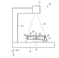
- FIG. 1 shows an example of an imaging device.
- the imaging device 10 has a light source 11 , an imaging sensor 12 , a support 13 , a base 14 and a stage 15 .
- the light source 11 is, for example, a laser diode.
- the imaging device 10 performs so-called lens-free imaging, in which an observation target is imaged without using an optical lens.
- the light source 11 may be configured by combining a light emitting diode and a pinhole.
- the light source 11 emits radial illumination light 16 toward the stage 15 .
- the illumination light 16 is coherent light.
- the wavelength of the illumination light 16 is 640 nm, 780 nm, or the like.
- the light source 11 is connected to one end of a substantially L-shaped support 13 .
- the other end of the support 13 is connected to the base 14 .
- the base 14 has a flat plate shape, and a stage 15 is provided substantially in the center.
- the stage 15 is provided with a recessed mounting portion 15A on which a culture container 20 for culturing the fertilized egg is mounted.
- the column 13 supports the light source 11 so that the light source 11 faces the imaging surface 12A of the imaging sensor 12 .
- a fertilized egg is an example of an “observation object” according to the technology of the present disclosure.
- the direction in which the light source 11 and the imaging surface 12A face each other is hereinafter referred to as the Z direction.
- the Z direction is also the irradiation direction of the illumination light 16 .
- a direction orthogonal to the Z direction is called an X direction.
- a direction orthogonal to the Z direction and the X direction is called the Y direction.
- the imaging surface 12A is orthogonal to the Z direction and parallel to the X and Y directions.
- the imaging sensor 12 is composed of, for example, a monochrome CMOS (Complementary Metal Oxide Semiconductor) image sensor.
- a culture container 20 is placed on the imaging surface 12A of the imaging sensor 12 .
- the culture container 20 is a shallow cylindrical container and is also called a culture dish.
- Culture vessel 20 is used with lid 25 (see FIG. 2).
- the culture container 20 is transparent and allows the illumination light 16 to pass therethrough.
- the diameter of the culture vessel 20 is about 30 to 60 mm.
- the thickness of the culture vessel 20 is approximately 10 to 20 mm.
- a fertilized egg 21 that has undergone in vitro fertilization is seeded in the culture container 20 .
- In vitro fertilization treatment includes microinsemination treatment performed under a microscope and normal in vitro fertilization treatment in which ovum and sperm are combined in a predetermined container.
- the method of fertilization of the fertilized egg 21 to be cultured does not matter.
- the fertilized egg 21 is, for example, a human fertilized egg.
- the fertilized egg 21 is almost spherical and has a diameter of about 100 to 200 ⁇ m.
- the fertilized egg 21 floats in the culture solution 22 that has been dropped into the culture container 20 .
- the culture medium 22 is covered with oil 23 filled in the culture container 20 .
- the oil 23 suppresses evaporation and pH change of the culture solution 22 .
- the fertilized egg 21 in the divided state is also called an embryo.
- a fertilized egg 21 in the present disclosure includes an embryo.
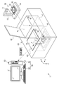
- FIG. 2 is a side view of the imaging device 10 on which the culture container 20 is placed. As shown in FIG. 2, the fertilized egg 21 is imaged by the imaging device 10 with the culture container 20 covered with the lid 25 .
- the imaging sensor 12 detects the illumination light 16 emitted from the light source 11 and transmitted through the culture container 20 . Specifically, the illumination light 16 is incident on the culture container 20 and diffracted by the fertilized egg 21 , thereby producing an interference fringe image reflecting the shape and internal structure of the fertilized egg 21 . An interference fringe image is also called a hologram image. The imaging sensor 12 captures an interference fringe image generated by the fertilized egg 21 .
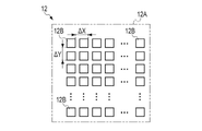
- FIG. 3 shows an example of the configuration of the imaging sensor 12.
- the imaging sensor 12 has a plurality of pixels 12B arranged on an imaging surface 12A.
- the pixel 12B is a photoelectric conversion element that outputs a pixel signal corresponding to the amount of incident light by photoelectrically converting incident light.
- the pixels 12B are arranged at equal pitches along the X and Y directions.
- the arrangement of the pixels 12B is a so-called square arrangement.
- the X direction is a direction perpendicular to the Z direction.
- the Y direction is a direction orthogonal to the X and Z directions.
- the pixels 12B are arranged at a first arrangement pitch ⁇ x in the X direction and arranged at a second arrangement pitch ⁇ y in the Y direction.
- the imaging sensor 12 captures light incident on the imaging surface 12A and outputs image data composed of pixel signals output from each of the pixels 12B.
- FIG. 4 shows how an interference fringe image is generated by irradiating the fertilized egg 21 with the illumination light 16 .
- a part of the illumination light 16 incident on the culture container 20 is diffracted by the fertilized egg 21 . That is, the illumination light 16 is divided into diffracted light 30 diffracted by the fertilized egg 21 and transmitted light 31 not diffracted by the fertilized egg 21 but transmitted through the incubation container 20 .
- the transmitted light 31 is a spherical wave or a plane wave.
- the diffracted light 30 and the transmitted light 31 pass through the bottom surface of the culture container 20 and enter the imaging surface 12A of the imaging sensor 12 .
- the diffracted light 30 and the transmitted light 31 interfere with each other to generate an interference fringe image 33 .
- the interference fringe image 33 is composed of bright portions 36 and dark portions 38 .
- the interference fringe image 33 is illustrated with circular bright portions 36 and dark portions 38 , but the shape of the interference fringe image 33 changes according to the shape and internal structure of the fertilized egg 21 .
- the imaging sensor 12 captures an optical image including the interference fringe image 33 formed on the imaging surface 12A and outputs image data including the interference fringe image 33 .
- FIG. 5 shows an example of the configuration of an imaging system.
- the imaging system 2 includes an imaging device 10 , an incubator 40 and an information processing device 50 .
- the incubator 40 is a multi-room incubator for fertilized eggs and is also called an embryo culture device.
- the fertilized egg 21 is cultured within the incubator 40 for a predetermined period (for example, seven days).
- the incubator 40 has a plurality of culture chambers 41, unlike a general incubator for culturing cells other than fertilized eggs. This is because the imaging device 10 is accommodated in each of the culture chambers 41 so that the fertilized egg 21 is managed individually so as not to be mistaken for someone else's fertilized egg 21 .
- the incubation room 41 is also referred to as an incubation chamber. Although two culture chambers 41 are provided in the incubator 40 shown in FIG. 5, the number of culture chambers 41 is not limited to this and can be changed as appropriate.
- Each of the culture chambers 41 is provided with an openable lid 42 .
- the incubator 40 is provided with a switch 43 for opening and closing the lid 42 for each culture chamber 41 .
- the lid 42 is opened and closed by a driving mechanism (not shown).
- the lid 42 may be configured to be manually opened and closed.
- the incubation chamber 41 is kept airtight when the lid 42 is closed.
- a mixed gas obtained by mixing carbon dioxide (CO 2 ) gas and nitrogen (N 2 ) gas with outside air (air) from an external gas cylinder (not shown) is passed through a HEPA filter (High Efficiency Particulate Air Filter). supplied via Heaters (not shown) are provided on the side and bottom surfaces of the culture chamber 41 .
- the incubation chamber 41 is controlled so that the concentration, temperature, and humidity of the mixed gas are kept constant, thereby maintaining a constant culture environment.
- the imaging device 10 has a size that allows it to be taken in and out of the culture room 41 . As shown in FIG. 5, one imaging device 10 is inserted into one incubation chamber 41 . That is, the lid 42 can be closed while the imaging device 10 with the culture container 20 placed thereon is inserted into the culture chamber 41 . As a result, while culturing the fertilized egg 21 in the culture chamber 41 , the image of the fertilized egg 21 can be captured by the imaging device 10 without removing the culture container 20 from the culture chamber 41 .
- the information processing device 50 is, for example, a desktop personal computer.
- a display 51 , a keyboard 52 , a mouse 53 and the like are connected to the information processing device 50 .
- the keyboard 52 and mouse 53 constitute an input device 54 for the user to enter information.
- the input device 54 also includes a touch panel and the like.
- the information processing device 50 exchanges data with the imaging devices 10 accommodated in each incubation room 41 by wireless communication.
- the imaging device 10 performs imaging periodically (for example, every 5 to 15 minutes).
- the information processing device 50 periodically receives image data including the interference fringe image 33 (see FIG. 4) from the imaging device 10, performs reconstruction processing based on the received image data, and reproduces the reconstruction generated by the reconstruction processing. View the composition image.
- a reconstructed image is also called a tomographic image.
- FIG. 6 shows an example of the internal configuration of the imaging device 10 and the information processing device 50.
- the imaging device 10 includes a processor 60, a storage device 61, a communication unit 62, a power supply unit 63, and a battery 64 in addition to the light source 11 and the imaging sensor 12. These are connected via a bus line 65. are interconnected.
- the processor 60 is, for example, an FPGA (Field Programmable Gate Array), and controls the operation of each unit in the imaging device 10.
- the storage device 61 is RAM (Random Access Memory), flash memory, or the like. The storage device 61 stores image data generated by the imaging device 10 and various data.
- the communication unit 62 performs wireless communication with the information processing device 50 .
- Processor 60 transmits image data to information processing device 50 via communication unit 62 .
- the battery 64 is a secondary battery such as a lithium polymer battery.
- the power supply unit 63 includes a power supply circuit and a charging control circuit.
- the power supply unit 63 supplies power supplied from the battery 64 to the processor 60 and the like. Further, the power supply unit 63 controls charging of the battery 64 with electric power supplied from the outside. Note that the power supply unit 63 may be configured to wirelessly charge the battery 64 .
- the information processing device 50 includes a processor 55 , a storage device 56 and a communication section 57 , which are interconnected via a bus line 58 . Also, the display 51 and the input device 54 are connected to the bus line 58 .
- the processor 55 is composed of, for example, a CPU (Central Processing Unit), and implements various functions by reading the operating program 56A and various data stored in the storage device 56 and executing the processes.
- a CPU Central Processing Unit
- the storage device 56 includes, for example, RAM, ROM (Read Only Memory), or a storage device.
- RAM is, for example, a volatile memory used as a work area or the like.
- the ROM is a nonvolatile memory such as a flash memory that holds the operating program 56A and various data, for example.
- the storage device is, for example, a HDD (Hard Disk Drive) or an SSD (Solid State Drive).
- the storage stores an OS (Operating System), application programs, image data, various data, and the like.
- the communication unit 57 performs wireless communication with the communication unit 62 of the imaging device 10 .
- the processor 55 receives image data transmitted from the imaging device 10 via the communication section 57 .
- the processor 55 also transmits a control signal for controlling imaging to the imaging device 10 via the communication unit 57 .
- the display 51 displays various screens.
- the information processing apparatus 50 receives input of operation instructions from the input device 54 through various screens.
- FIG. 7 shows an example of the functional configuration of the information processing device 50.
- the functions of information processing device 50 are realized by processor 55 executing processing based on operation program 56A.
- the processor 55 includes an imaging control section 70 , an image data acquisition section 71 , a reconstruction processing section 72 , a display control section 73 , a feature quantity extraction section 74 and a determination section 75 .
- the imaging control unit 70 controls the operation of the imaging device 10 . Specifically, the imaging control unit 70 controls the operation of generating the illumination light 16 by the light source 11 and the imaging operation of the imaging sensor 12 by transmitting control signals to the imaging device 10 .
- the operation of generating the illumination light 16 by the light source 11 and the imaging operation of the imaging sensor 12 are collectively referred to as the imaging operation of the imaging device 10 .
- the imaging control unit 70 causes the imaging device 10 to start imaging operation based on the operation signal input from the input device 54 .
- the image data acquisition unit 71 acquires generated image data transmitted from the imaging device 10 after the imaging device 10 has captured an image of the fertilized egg 21 in the culture container 20 .
- the image data acquisition unit 71 supplies the acquired image data to the reconstruction processing unit 72 .
- the reconstruction processing unit 72 generates a reconstructed image by performing calculations based on the image data. For example, as shown in FIG. 8, the reconstruction processing unit 72 changes the reconstruction position P by a constant value in the Z direction, and generates a reconstructed image each time the reconstruction position P is changed.
- the reconstruction position P is a position represented by a distance d from the imaging surface 12A of the imaging sensor 12 toward the light source 11 (so-called depth position).
- the reconstruction position P will also be referred to as the focal position.
- the reconstruction processing unit 72 performs reconstruction processing based on, for example, the Fresnel transform equations represented by the following equations (1) to (3).
- I(x, y) represents image data.
- x represents the coordinate in the X direction of the pixel 12B (see FIG. 3) of the image sensor 12;
- y represents the coordinate of the pixel 12B in the Y direction.
- ⁇ x is the aforementioned first array pitch
- ⁇ y is the aforementioned second array pitch (see FIG. 3).
- ⁇ is the wavelength of the illumination light 16 .
- ⁇ (m,n) is a complex amplitude image obtained by Fresnel transforming the interference fringe image included in the image data.
- Nx represents the number of pixels in the X direction of the image data.
- Ny represents the number of pixels in the Y direction of the image data.
- a 0 (m,n) is an intensity distribution image representing intensity components of the complex amplitude image ⁇ (m,n).
- ⁇ 0 (m,n) is a phase distribution image representing the phase component of the complex amplitude image ⁇ (m,n).
- the reconstruction processing unit 72 obtains a complex amplitude image ⁇ (m,n) based on equation (1), and applies the obtained complex amplitude image ⁇ (m,n) to equation (2) or equation (3). By doing so, an intensity distribution image A 0 (m, n) or a phase distribution image ⁇ 0 (m, n) is obtained.
- the reconstruction processing unit 72 obtains one of the intensity distribution image A 0 (m, n) and the phase distribution image ⁇ 0 (m, n) and outputs it as a reconstructed image.
- the reconstruction processing unit 72 outputs the phase distribution image ⁇ 0 (m, n) as a reconstructed image.
- the phase distribution image ⁇ 0 (m, n) is an image representing the refractive index distribution of the observed object. Since the fertilized egg 21, which is the object to be observed in this embodiment, is translucent, most of the illumination light 16 is transmitted or diffracted without being absorbed by the fertilized egg 21, so the intensity distribution is hardly any image appears in Therefore, in this embodiment, it is preferable to use the phase distribution image ⁇ 0 (m, n) as the reconstructed image.
- the reconstruction processing unit 72 is not limited to the method using the Fresnel transform formula, and may perform the reconstruction processing using the Fourier iterative phase retrieval method or the like.
- the display control unit 73 causes the display 51 to display the reconstructed image generated by the reconstruction processing unit 72 .
- the display 51 may display a reconstructed image at one focus position, or may display reconstructed images at a plurality of focus positions. Also, the focus position of the reconstructed image displayed on the display 51 may be set or selected by the user operating the input device 54 .
- the fertilized egg 21 has a thickness of about 100 to 200 ⁇ m and floats in the culture solution 22, it is difficult to adjust the focal position for the pronucleus inside the fertilized egg 21 in conventional microscopic observation. For this reason, for example, in the conventional technique described in Japanese Patent Application Laid-Open No. 2018-093795, a plurality of images with different focal positions are captured. On the other hand, in the lens-free imaging of the present disclosure, it is possible to generate a reconstructed image at an arbitrary focal position based on image data obtained by one imaging.
- the feature amount extraction unit 74 extracts image feature amounts from the image data acquired by the image data acquisition unit 71 .
- the feature quantity extraction unit 74 searches for the interference fringe image 33 from the image data by performing template matching using the interference fringe image 33 shown in FIG. 4 as a template.
- the feature amount extraction unit 74 outputs a correlation value representing the degree of matching between the image included in the image data and the interference fringe image 33 to the determination unit 75 as a feature amount.
- the determination unit 75 determines the quality of the interference fringe image included in the image data acquired by the image data acquisition unit 71 based on the feature amount input from the feature amount extraction unit 74 .
- the “quality” corresponds to the degree of similarity with the interference fringe image 33 obtained by imaging the fertilized egg 21 .
- the quality of the interference fringes to be determined is higher as the degree of similarity with the interference fringe image 33 of the fertilized egg 21 is higher.
- the determination unit 75 determines the quality of the interference fringe image based on whether the correlation value is equal to or greater than a reference value.
- the determination unit 75 outputs the determination result R of the quality of the interference fringe image to the reconstruction processing unit 72 and the display control unit 73 .
- the determination result R includes information indicating whether or not to continue the reconstruction processing by the reconstruction processing unit 72 according to the quality of the interference fringe image.
- the determination result R may be a permission signal R1 that permits the execution of reconstruction processing in response to the fact that the quality of the interference fringe image is above a certain level (that is, the correlation value is above the reference value), or a permission signal R1 that permits the execution of the reconstruction process if the quality of the interference fringe image is above a certain level.
- a disallowing signal R2 is included that disallows execution of the reconstruction process in response to being less than (ie, the correlation value is less than the reference value).
- the reconstruction processing unit 72 determines whether the reconstruction processing can be executed. If the determination result R includes the permission signal R1, the reconstruction processing unit 72 executes the reconstruction processing. Further, when the determination result R includes the disallowing signal R2, the reconstruction processing unit 72 does not perform the reconstruction processing.
- the display control unit 73 causes the display 51 to display a message based on the determination result R input from the determination unit 75 .
- the display control unit 73 causes the display 51 to display a message indicating that the reconstruction process is not executed due to the low quality of the interference fringe image.
- the display control unit 73 preferably causes the display 51 to display a message prompting the user to perform re-imaging.
- the display control unit 73 instructs the user to It is preferable to display a message on the display 51 urging the user to confirm the condition of the object and then retake the image.
- FIG. 9 to 11 show examples of judgment results R obtained by judging the quality of the interference fringe image.
- FIG. 9 shows an example of image data generated by the imaging device 10 when water droplets 80 adhere to the lid 25 .
- the illumination light 16 is incident on the water droplets 80 and diffuses into diffused light.
- the interference fringe image 33 does not appear in the image data D, and diffused light that is diffused as a whole is imaged.
- the correlation value calculated by template matching as the feature amount extracted by the feature amount extraction unit 74 is less than the reference value.
- the determination unit 75 determines that the quality of the interference fringe image is below a certain level, and outputs the determination result R including the disapproval signal R2 to the reconstruction processing unit 72 and the display control unit 73 .
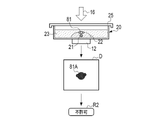
- FIG. 10 shows an example of image data generated by the imaging device 10 when air bubbles 81 are mixed in the culture solution 22.
- FIG. 10 when air bubbles 81 are present in the culture solution 22, the difference in refractive index between the culture solution 22 and the air bubbles 81 (that is, air) causes light refraction.
- the interference fringe image 33 does not appear in the image data D, and only the shadow 81A of the air bubble 81 is imaged.
- the correlation value calculated by template matching as the feature amount extracted by the feature amount extraction unit 74 is less than the reference value.
- the determination unit 75 determines that the quality of the interference fringe image is below a certain level, and outputs the determination result R including the disapproval signal R2 to the reconstruction processing unit 72 and the display control unit 73 .
- FIG. 11 shows an example of image data generated by the imaging device 10 when water droplets are not attached to the lid 25 and air bubbles are not mixed into the culture solution 22 .
- the image data D includes an interference fringe image 33 based on the fertilized egg 21 when the image of the fertilized egg 21 is satisfactorily performed.
- the correlation value calculated by template matching as the feature amount extracted by the feature amount extraction unit 74 is equal to or greater than the reference value.
- the determination unit 75 determines that the quality of the interference fringe image is above a certain level, and outputs the determination result R including the permission signal R1 to the reconstruction processing unit 72 and the display control unit 73 .
- the determination unit 75 determines the presence or absence of the interference fringe image 33 in the image data, and outputs the determination result R according to the presence or absence of the interference fringe image 33. That is, in this embodiment, whether or not the reconstruction process can be executed is determined based on the presence or absence of the interference fringe image 33 .
- the user places the culture container 20 on the stage 15 of the imaging device 10 and then inserts the imaging device 10 into the culture chamber 41 of the incubator 40 .
- At least one imaging device 10 may be inserted into the plurality of culture chambers 41 .
- the user closes the lid 42 of the culture chamber 41 and causes the incubator 40 to start culturing.
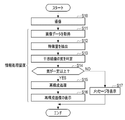
- the imaging device 10 images the fertilized egg 21 in the incubation container 20 under the control of the information processing device 50 (step S10).
- the imaging device 10 transmits image data generated by performing an imaging operation to the information processing device 50 .
- the information processing device 50 acquires the image data transmitted from the imaging device 10 by the image data acquisition unit 71 (step S11).
- the feature quantity extraction unit 74 of the information processing device 50 extracts a feature quantity from the image data acquired by the image data acquisition unit 71 (step S12). For example, the feature quantity extraction unit 74 extracts a correlation value representing the degree of matching with the interference fringe image 33 as a feature quantity by template matching.
- the determination unit 75 determines the quality of the interference fringe image included in the image data based on the feature amount extracted by the feature amount extraction unit 74, and outputs the determination result R to the reconstruction processing unit 72 and the display control unit 73. (step S13).
- a permission signal R1 is output as the determination result R from the determination unit 75 to the reconstruction processing unit 72 and the display control unit 73.
- the reconstruction processing unit 72 generates a reconstructed image by performing reconstruction processing based on the image data acquired by the image data acquisition unit 71 (step S15).
- the display control unit 73 causes the display 51 to display the reconstructed image generated by the reconstruction processing unit 72 (step S16).
- step S14 when the quality of the interference fringe image is less than a certain value (step S14: NO), a disapproval signal R2 is output from the determination unit 75 to the reconstruction processing unit 72 and the display control unit 73 as the determination result R. .
- the reconstruction processing unit 72 does not perform reconstruction processing.
- the display control unit 73 causes the display 51 to display a message indicating that the reconstruction process is not executed due to the low quality of the interference fringe image (step S17).
- the quality of the interference fringe image included in the image data obtained by the imaging device 10 is determined. Do not perform reconstruction processing on Therefore, when the quality of the interference fringe image is low, the user does not need to wait for the completion of the reconstruction process, and after confirming whether foreign matter is attached to or mixed with the culture container 20 or the lid 25, Early retakes can be performed. Therefore, observation efficiency of the observed object is improved.
- the feature quantity extraction unit 74 extracts the correlation value representing the degree of matching with the interference fringe image 33 as the feature quantity by template matching. You may In this case, for example, the feature amount extraction unit 74 extracts frequency characteristics by performing frequency analysis using Fourier transform or the like on the image data.
- the determination unit 75 determines the quality of the interference fringe image based on the frequency characteristic as the feature amount. The determining unit 75 determines that the closer the frequency characteristic extracted from the image data D to be determined to the frequency characteristic of the interference fringe image 33 of the fertilized egg 21, the higher the quality.
- the quality of the interference fringe image is determined based on a plurality of image data obtained by imaging a plurality of times.
- the light source 11 may be a laser light source in which a plurality of light emitting points (for example, 36 light emitting points) are arranged in a two-dimensional array.
- a vertical cavity surface emitting laser (Vertical Cavity Surface Emitting Laser) can be used.
- a high-resolution interference fringe image (so-called super-resolution interference fringe image) is included by synthesizing a plurality of image data obtained by performing an imaging operation of the imaging sensor 12 while sequentially emitting light from a plurality of light-emitting points. Image data is obtained. By reconstructing this image data, a reconstructed image with high image quality can be obtained.
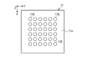
- FIG. 13 shows the configuration of the light emitting surface 11A of the light source 11 included in the imaging device 10 according to the second embodiment.
- the light emitting surface 11A is arranged at a position facing the imaging sensor 12 .
- a plurality of light emitting points 11B are arranged in a two-dimensional array on the light emitting surface 11A.
- the arrangement pitch of the light emitting points 11B is about 10 ⁇ m to 100 ⁇ m.
- Each of the light emitting points 11B is selected in order to emit illumination light 16.
- the light emission time interval of the plurality of light emission points 11B is several milliseconds.
- the arrangement pitch of the light emitting points 11B only needs to be different from the arrangement pitch of the pixels 12B (the first arrangement pitch ⁇ x and the second arrangement pitch ⁇ y), and does not necessarily have to be smaller than the arrangement pitch of the pixels 12B. For example, even if the light emitting point 11B is located directly above the adjacent pixel 12B, the array pitch of the light emitting point 11B does not have to match the array pitch of the pixels 12B. In this case, since different positions on the pixels 12B are illuminated with the illumination light 16, when combining a plurality of image data, different pixels 12B that are directly below the respective light emitting points 11B and illuminated with the illumination light 16 can be selected. It is possible to generate image data including a super-resolution interference fringe image by regarding them as the same pixel and aligning them with an accuracy of one pixel or less.
- the light-emitting points 11B are arranged in a 6 ⁇ 6 square, and 36 light-emitting points 11B are provided on the light-emitting surface 11A.
- the imaging sensor 12 performs an imaging operation and generates image data each time each of the light emitting points 11B emits light.
- the imaging device 10 transmits to the information processing device 50 a plurality of image data obtained by the imaging sensor 12 performing imaging a plurality of times.
- FIG. 14 shows an example of the functional configuration of an information processing device 50 according to the second embodiment.
- the processor 55 includes an imaging control unit 70, an image data acquisition unit 71, a reconstruction processing unit 72, a display control unit 73, a feature amount extraction unit 74, and a determination unit 75.
- a super-resolution processing unit 76 is configured.
- FIG. 15 schematically shows super-resolution processing by the super-resolution processing unit 76.
- the plurality of light emitting points 11B provided on the light source 11 sequentially emit light one by one according to the control from the imaging control section 70.
- t represents time.
- the interference fringe image 33 included in the image data D obtained by the imaging sensor 12 capturing images at each time t in the time series t t1, t2, t3 .
- the position in D is shifted.
- the super-resolution processing unit 76 aligns and synthesizes a plurality of image data D to generate image data DS including a super-resolution interference fringe image 33S.
- the super-resolution processing unit 76 outputs the generated image data DS to the reconstruction processing unit 72 .
- the feature quantity extraction unit 74 calculates correlation values of successive interference fringe images in time series as feature quantities for each of the plurality of image data D.
- FIG. The determination unit 75 determines whether or not the correlation value is greater than or equal to the reference value. When the correlation value is equal to or greater than the reference value, the determination unit 75 determines that the quality of the interference fringe image is equal to or higher than a certain level, and outputs a determination result R including the permission signal R1. Further, when the correlation value is less than the reference value, the determination section 75 determines that the quality of the interference fringe image is less than a certain level, and outputs a determination result R including a disallowance signal R2.
- the feature quantity extraction unit 74 is not limited to the correlation value of the time-series continuous interference fringe images, and may calculate the difference value of the time-series continuous interference fringe images as the feature quantity. Even when the fertilized egg 21 is translated, the difference value can be calculated by aligning the successive interference fringe images in time series and taking the difference. In other words, the feature amount extraction unit 74 may calculate the feature amount based on the temporal change of the interference fringe images that are continuous in time series.
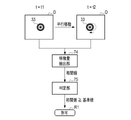
- 16 and 17 show an example of calculating the correlation value between the image data D obtained at time t1 and the image data D obtained at time t2.
- FIG. 16 shows an example in which the pattern of the interference fringe image 33 in the image data D changes due to the rotation of the fertilized egg 21 between time t1 and time t2. Since the fertilized egg 21 floats in the culture solution 22, rotation is likely to occur. When the fertilized egg 21 rotates, the position of the pronucleus inside the fertilized egg 21 changes, so that the pattern of the interference fringe image 33 changes. In this way, when the pattern of the interference fringe image 33 changes due to the rotation of the fertilized egg 21, the correlation value calculated by the feature amount extraction unit 74 is less than the reference value. In this case, the determination unit 75 determines that the quality of the interference fringe image is less than a certain level, and outputs the determination result R including the non-permission signal R2.
- FIG. 17 shows an example in which the interference fringe image 33 in the image data D moves linearly due to parallel movement of the fertilized egg 21 between time t1 and time t2.
- the pattern of the interference fringe image 33 does not change.
- the correlation value calculated by the feature quantity extraction unit 74 is equal to or greater than the reference value.
- the determination unit 75 determines that the quality of the interference fringe image is above a certain level, and outputs the determination result R including the permission signal R1.
- the super-resolution processing unit 76 can align the interference fringe image 33, so the image quality of the image data DS generated by the super-resolution processing unit 76 is does not decrease.
- the pattern of the interference fringe image 33 may be generated by the cell division of the fertilized egg 21 in addition to the rotation of the fertilized egg 21 .
- the temperature changes greatly, so that the fertilized egg 21 moves greatly, and the pattern of the interference fringe image 33 may change.
- whether or not super-resolution processing and reconstruction processing can be executed is determined based on the temporal change in the pattern of the interference fringe image 33 .
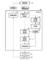
- imaging is performed a plurality of times while changing the light emitting point 11B of the light source 11 (step S20).
- the imaging device 10 transmits to the information processing device 50 a plurality of image data generated by performing imaging operations a plurality of times.
- the information processing device 50 uses the image data acquisition unit 71 to acquire a plurality of image data transmitted from the imaging device 10 (step S21).
- the feature amount extraction unit 74 of the information processing device 50 extracts feature amounts from the plurality of image data acquired by the image data acquisition unit 71 (step S22).
- the correlation value of the interference fringe images that are continuous in time series is calculated as the feature amount for each of the plurality of image data.
- the determination unit 75 determines the quality of the interference fringe image included in the image data based on the feature amount extracted by the feature amount extraction unit 74, and the determination result R is transferred to the super-resolution processing unit 76 for reconstruction processing. It outputs to the unit 72 and the display control unit 73 (step S23). In this embodiment, the determination unit 75 determines that the quality of the interference fringe image is less than a certain level when at least one of the plurality of correlation values calculated by the feature amount extraction unit 74 is less than the reference value. Then, the judgment result R including the disallowing signal R2 is output.
- the determination unit 75 determines that the quality of the interference fringe image is equal to or higher than a certain value, and outputs the permission signal R1. Output the determination result R including.
- the super-resolution processing unit 76 When the quality of the interference fringe image is above a certain level (step S24: YES), the super-resolution processing unit 76 performs super-resolution processing based on the plurality of image data acquired by the image data acquiring unit 71. generates image data including a super-resolution interference fringe image (step S25).
- the reconstruction processing unit 72 generates a reconstructed image by performing reconstruction processing based on the image data generated by the super-resolution processing unit 76 (step S26).
- the display control unit 73 causes the display 51 to display the reconstructed image generated by the reconstruction processing unit 72 (step S27).
- step S24 when the quality of the interference fringe image is less than a certain value (step S24: NO), the super-resolution processing unit 76 does not execute super-resolution processing, and the reconstruction processing unit 72 executes reconstruction processing. do not do.
- the display control unit 73 causes the display 51 to display a message indicating that the reconstruction process is not executed due to the low quality of the interference fringe image (step S28).
- the quality of the interference fringe image is determined based on the time change of the interference fringe image included in the plurality of image data obtained by the imaging device 10. and do not perform super-resolution processing and reconstruction processing if the quality is less than a certain value. Therefore, when the quality of the interference fringe image is low, the user does not need to wait for the super-resolution processing and the reconstruction processing to be completed, and can quickly perform re-imaging after confirming the state of the fertilized egg 21. can be done. Therefore, observation efficiency of the observed object is improved.
- the feature quantity extraction unit 74 and the determination unit 75 perform processing after the imaging device 10 has generated a plurality of pieces of image data through a plurality of imaging operations.
- the processing may be performed each time an imaging operation is performed and one piece of image data is generated. That is, it may be determined whether or not to continue the imaging operation based on the determination result of the quality of the interference fringe image while the imaging device 10 is performing imaging a plurality of times. In this case, the imaging operation is stopped when it is determined that the quality of the interference fringe image is below a certain level.
- the interference fringe image it may be determined whether to continue the imaging operation and reconstruction processing based on the determination result of the quality of the image. In this case, if it is determined that the quality of the interference fringe image is below a certain level, the imaging operation and the reconstruction process are stopped.
- the imaging device 10 and the information processing device 50 are separate devices, but the imaging device 10 and the information processing device 50 may be integrated into one device. . Furthermore, the imaging device 10, the information processing device 50, and the incubator 40 may be integrally configured as one device.
- the observation object is the fertilized egg, but the observation object may be floating cells other than the fertilized egg.
- Suspended cells are cells that float in a culture medium. Floating cells include, in addition to fertilized eggs, CHO (Chinese Hamster Ovary) cells used for antibody production.
- the imaging system 2 relates to a technique called lens-free imaging in which the imaging device 10 is not equipped with an optical lens.
- the technology of the present disclosure is applicable to digital holography in general (for example, when using reference light).
- the hardware configuration of the computer that constitutes the information processing device 50 can be configured with a plurality of computers separated as hardware for the purpose of improving processing capability and reliability.
- the hardware configuration of the computer of the information processing device 50 can be appropriately changed according to required performance such as processing power, safety, and reliability.
- application programs such as the operating program 56A can be duplicated or distributed and stored in multiple storage devices for the purpose of ensuring safety and reliability. .
- the imaging control unit 70 the image data acquisition unit 71, the reconstruction processing unit 72, the display control unit 73, the feature amount extraction unit 74, the determination unit 75, and the super-resolution processing unit 76.
- a processing unit processing unit
- various types of processors shown below can be used.
- the various processors include, as described above, a CPU, which is a general-purpose processor that executes software (operation program 56A) and functions as various processing units, as well as FPGAs and the like whose circuit configuration can be changed after manufacture.
- Programmable Logic Device which is a processor, ASIC (Application Specific Integrated Circuit), etc. Includes a dedicated electric circuit, which is a processor with a circuit configuration specially designed to execute specific processing. .
- One processing unit may be configured with one of these various processors, or a combination of two or more processors of the same or different type (for example, a combination of a plurality of FPGAs and/or a CPU and combination with FPGA). Also, a plurality of processing units may be configured by one processor.
- a single processor is configured by combining one or more CPUs and software.
- a processor functions as multiple processing units.
- SoC System On Chip
- a processor that realizes the functions of the entire system including multiple processing units with a single IC (Integrated Circuit) chip. be.
- the various processing units are configured using one or more of the above various processors as a hardware structure.
Landscapes
- Engineering & Computer Science (AREA)
- Health & Medical Sciences (AREA)
- Chemical & Material Sciences (AREA)
- General Physics & Mathematics (AREA)
- Physics & Mathematics (AREA)
- Life Sciences & Earth Sciences (AREA)
- Theoretical Computer Science (AREA)
- General Health & Medical Sciences (AREA)
- Bioinformatics & Cheminformatics (AREA)
- Organic Chemistry (AREA)
- Biotechnology (AREA)
- Wood Science & Technology (AREA)
- Zoology (AREA)
- Analytical Chemistry (AREA)
- Biochemistry (AREA)
- Computer Vision & Pattern Recognition (AREA)
- Radiology & Medical Imaging (AREA)
- Medical Informatics (AREA)
- Quality & Reliability (AREA)
- Nuclear Medicine, Radiotherapy & Molecular Imaging (AREA)
- Sustainable Development (AREA)
- Microbiology (AREA)
- Pathology (AREA)
- Biomedical Technology (AREA)
- Medicinal Chemistry (AREA)
- General Engineering & Computer Science (AREA)
- Genetics & Genomics (AREA)
- Immunology (AREA)
- Investigating Or Analysing Materials By Optical Means (AREA)
Priority Applications (2)
| Application Number | Priority Date | Filing Date | Title |
|---|---|---|---|
| JP2023502108A JP7735383B2 (ja) | 2021-02-26 | 2021-12-22 | 情報処理装置、情報処理方法、及びプログラム |
| US18/448,606 US20230401715A1 (en) | 2021-02-26 | 2023-08-11 | Information processing apparatus, information processing method, and program |
Applications Claiming Priority (2)
| Application Number | Priority Date | Filing Date | Title |
|---|---|---|---|
| JP2021-031211 | 2021-02-26 | ||
| JP2021031211 | 2021-02-26 |
Related Child Applications (1)
| Application Number | Title | Priority Date | Filing Date |
|---|---|---|---|
| US18/448,606 Continuation US20230401715A1 (en) | 2021-02-26 | 2023-08-11 | Information processing apparatus, information processing method, and program |
Publications (1)
| Publication Number | Publication Date |
|---|---|
| WO2022181024A1 true WO2022181024A1 (ja) | 2022-09-01 |
Family
ID=83048040
Family Applications (1)
| Application Number | Title | Priority Date | Filing Date |
|---|---|---|---|
| PCT/JP2021/047727 Ceased WO2022181024A1 (ja) | 2021-02-26 | 2021-12-22 | 情報処理装置、情報処理方法、及びプログラム |
Country Status (3)
| Country | Link |
|---|---|
| US (1) | US20230401715A1 (https=) |
| JP (1) | JP7735383B2 (https=) |
| WO (1) | WO2022181024A1 (https=) |
Citations (5)
| Publication number | Priority date | Publication date | Assignee | Title |
|---|---|---|---|---|
| WO2009125578A1 (ja) * | 2008-04-07 | 2009-10-15 | 富士フイルム株式会社 | 画像処理システム、画像処理方法、およびコンピュータ読取可能な媒体 |
| US20150079621A1 (en) * | 2012-09-13 | 2015-03-19 | Purdue Research Foundation | Motility-Contrast Imaging for Oocyte and Embryo Viability Assessment |
| WO2020039470A1 (ja) * | 2018-08-20 | 2020-02-27 | ダットジャパン株式会社 | 画像処理システム |
| WO2020261826A1 (ja) * | 2019-06-28 | 2020-12-30 | 富士フイルム株式会社 | 画像処理装置、評価システム、画像処理プログラム及び画像処理方法 |
| WO2020262551A1 (ja) * | 2019-06-26 | 2020-12-30 | 株式会社島津製作所 | 細胞機能の評価方法及び細胞解析装置 |
-
2021
- 2021-12-22 WO PCT/JP2021/047727 patent/WO2022181024A1/ja not_active Ceased
- 2021-12-22 JP JP2023502108A patent/JP7735383B2/ja active Active
-
2023
- 2023-08-11 US US18/448,606 patent/US20230401715A1/en active Pending
Patent Citations (5)
| Publication number | Priority date | Publication date | Assignee | Title |
|---|---|---|---|---|
| WO2009125578A1 (ja) * | 2008-04-07 | 2009-10-15 | 富士フイルム株式会社 | 画像処理システム、画像処理方法、およびコンピュータ読取可能な媒体 |
| US20150079621A1 (en) * | 2012-09-13 | 2015-03-19 | Purdue Research Foundation | Motility-Contrast Imaging for Oocyte and Embryo Viability Assessment |
| WO2020039470A1 (ja) * | 2018-08-20 | 2020-02-27 | ダットジャパン株式会社 | 画像処理システム |
| WO2020262551A1 (ja) * | 2019-06-26 | 2020-12-30 | 株式会社島津製作所 | 細胞機能の評価方法及び細胞解析装置 |
| WO2020261826A1 (ja) * | 2019-06-28 | 2020-12-30 | 富士フイルム株式会社 | 画像処理装置、評価システム、画像処理プログラム及び画像処理方法 |
Also Published As
| Publication number | Publication date |
|---|---|
| US20230401715A1 (en) | 2023-12-14 |
| JPWO2022181024A1 (https=) | 2022-09-01 |
| JP7735383B2 (ja) | 2025-09-08 |
Similar Documents
| Publication | Publication Date | Title |
|---|---|---|
| US10754138B2 (en) | Multi-well fourier ptychographic and fluorescence imaging | |
| US20230005281A1 (en) | Adaptive sensing based on depth | |
| EP2446251B1 (en) | Analysis of ova or embryos with digital holographic imaging | |
| CN111630564B (zh) | 图像处理方法、程序及记录介质 | |
| US20150098126A1 (en) | Multiview Light-Sheet Microscopy | |
| US20130093871A1 (en) | Omnidirectional super-resolution microscopy | |
| US11530434B2 (en) | Cell mass evaluation method and device for analyzing state of cell mass | |
| CN111630366A (zh) | 图像处理方法、程序及记录介质 | |
| JP2018117557A (ja) | 画像生成装置及び画像生成方法 | |
| CN119148490B (zh) | 一种混合数字全息与傅里叶叠层的合成孔径定量相位成像方法 | |
| CN118067001B (zh) | 一种结合光瞳函数的光源位置精确校正方法 | |
| CN117099128B (zh) | 细胞计数方法、以及计算机可读介质 | |
| JP7822740B2 (ja) | タイムラプスイメージングシステム | |
| JP7812832B2 (ja) | イメージングシステム | |
| WO2022181024A1 (ja) | 情報処理装置、情報処理方法、及びプログラム | |
| JP7382289B2 (ja) | 画像処理方法、プログラムおよび記録媒体 | |
| US12482214B2 (en) | Imaging apparatus and information processing apparatus | |
| JP7382290B2 (ja) | 画像処理方法、プログラムおよび記録媒体 | |
| JP7767182B2 (ja) | 解析方法および解析装置 | |
| CN119757342B (zh) | 细胞组织形貌显微成像方法及其成像装置 | |
| JP7754932B2 (ja) | 試料観察装置及び試料観察方法 | |
| JP7694808B2 (ja) | 反射型明視野顕微鏡、観察方法、及びプログラム | |
| RU132699U1 (ru) | Офтальмологический капилляроскоп | |
| WO2025023131A1 (ja) | 情報処理装置、細胞評価システム、情報処理方法、プログラム及び学習方法 | |
| Berdeu | 3D lens-free imaging of 3D cell culture |
Legal Events
| Date | Code | Title | Description |
|---|---|---|---|
| 121 | Ep: the epo has been informed by wipo that ep was designated in this application |
Ref document number: 21928117 Country of ref document: EP Kind code of ref document: A1 |
|
| WWE | Wipo information: entry into national phase |
Ref document number: 2023502108 Country of ref document: JP |
|
| NENP | Non-entry into the national phase |
Ref country code: DE |
|
| 122 | Ep: pct application non-entry in european phase |
Ref document number: 21928117 Country of ref document: EP Kind code of ref document: A1 |