WO2022181024A1 - Information processing device, information processing method, and program - Google Patents
Information processing device, information processing method, and program Download PDFInfo
- Publication number
- WO2022181024A1 WO2022181024A1 PCT/JP2021/047727 JP2021047727W WO2022181024A1 WO 2022181024 A1 WO2022181024 A1 WO 2022181024A1 JP 2021047727 W JP2021047727 W JP 2021047727W WO 2022181024 A1 WO2022181024 A1 WO 2022181024A1
- Authority
- WO
- WIPO (PCT)
- Prior art keywords
- image data
- interference fringe
- image
- information processing
- imaging
- Prior art date
Links
- 230000010365 information processing Effects 0.000 title claims abstract description 55
- 238000003672 processing method Methods 0.000 title claims description 8
- 238000012545 processing Methods 0.000 claims abstract description 109
- 238000005286 illumination Methods 0.000 claims abstract description 26
- 238000003384 imaging method Methods 0.000 claims description 153
- 238000000034 method Methods 0.000 claims description 20
- 230000008569 process Effects 0.000 claims description 16
- 230000008859 change Effects 0.000 claims description 10
- 230000001678 irradiating effect Effects 0.000 claims description 10
- 238000007667 floating Methods 0.000 claims description 4
- 230000002123 temporal effect Effects 0.000 claims description 4
- 238000004458 analytical method Methods 0.000 claims description 3
- 239000000284 extract Substances 0.000 abstract description 9
- 235000013601 eggs Nutrition 0.000 description 59
- 238000000605 extraction Methods 0.000 description 26
- 239000011295 pitch Substances 0.000 description 13
- 238000004891 communication Methods 0.000 description 11
- 238000009826 distribution Methods 0.000 description 11
- 238000010586 diagram Methods 0.000 description 10
- 238000011534 incubation Methods 0.000 description 10
- 238000003860 storage Methods 0.000 description 10
- 210000004027 cell Anatomy 0.000 description 8
- 238000012258 culturing Methods 0.000 description 6
- 238000005516 engineering process Methods 0.000 description 6
- XLYOFNOQVPJJNP-UHFFFAOYSA-N water Substances O XLYOFNOQVPJJNP-UHFFFAOYSA-N 0.000 description 6
- 239000008186 active pharmaceutical agent Substances 0.000 description 5
- 230000006870 function Effects 0.000 description 5
- 239000007789 gas Substances 0.000 description 5
- 230000004720 fertilization Effects 0.000 description 4
- 238000001093 holography Methods 0.000 description 4
- 238000000338 in vitro Methods 0.000 description 3
- 210000001161 mammalian embryo Anatomy 0.000 description 3
- 230000003287 optical effect Effects 0.000 description 3
- CURLTUGMZLYLDI-UHFFFAOYSA-N Carbon dioxide Chemical compound O=C=O CURLTUGMZLYLDI-UHFFFAOYSA-N 0.000 description 2
- 238000004364 calculation method Methods 0.000 description 2
- 230000001427 coherent effect Effects 0.000 description 2
- 230000007423 decrease Effects 0.000 description 2
- 239000001963 growth medium Substances 0.000 description 2
- 238000002156 mixing Methods 0.000 description 2
- 239000000203 mixture Substances 0.000 description 2
- 238000012986 modification Methods 0.000 description 2
- 230000004048 modification Effects 0.000 description 2
- 230000004044 response Effects 0.000 description 2
- 239000004065 semiconductor Substances 0.000 description 2
- IJGRMHOSHXDMSA-UHFFFAOYSA-N Atomic nitrogen Chemical compound N#N IJGRMHOSHXDMSA-UHFFFAOYSA-N 0.000 description 1
- 241000699802 Cricetulus griseus Species 0.000 description 1
- 102000002322 Egg Proteins Human genes 0.000 description 1
- 108010000912 Egg Proteins Proteins 0.000 description 1
- WHXSMMKQMYFTQS-UHFFFAOYSA-N Lithium Chemical compound [Li] WHXSMMKQMYFTQS-UHFFFAOYSA-N 0.000 description 1
- 230000015572 biosynthetic process Effects 0.000 description 1
- 229910002092 carbon dioxide Inorganic materials 0.000 description 1
- 239000001569 carbon dioxide Substances 0.000 description 1
- 230000032823 cell division Effects 0.000 description 1
- 238000006243 chemical reaction Methods 0.000 description 1
- 230000000295 complement effect Effects 0.000 description 1
- 238000007796 conventional method Methods 0.000 description 1
- 238000001704 evaporation Methods 0.000 description 1
- 230000008020 evaporation Effects 0.000 description 1
- 230000016784 immunoglobulin production Effects 0.000 description 1
- 229910052744 lithium Inorganic materials 0.000 description 1
- 238000004519 manufacturing process Methods 0.000 description 1
- 230000007246 mechanism Effects 0.000 description 1
- 229910044991 metal oxide Inorganic materials 0.000 description 1
- 150000004706 metal oxides Chemical class 0.000 description 1
- 210000001672 ovary Anatomy 0.000 description 1
- 210000004681 ovum Anatomy 0.000 description 1
- 229920000642 polymer Polymers 0.000 description 1
- 239000007787 solid Substances 0.000 description 1
- 238000003786 synthesis reaction Methods 0.000 description 1
- 230000002194 synthesizing effect Effects 0.000 description 1
- 230000001131 transforming effect Effects 0.000 description 1
Images


Classifications
-
- G—PHYSICS
- G06—COMPUTING; CALCULATING OR COUNTING
- G06T—IMAGE DATA PROCESSING OR GENERATION, IN GENERAL
- G06T7/00—Image analysis
- G06T7/0002—Inspection of images, e.g. flaw detection
- G06T7/0012—Biomedical image inspection
- G06T7/0014—Biomedical image inspection using an image reference approach
- G06T7/0016—Biomedical image inspection using an image reference approach involving temporal comparison
-
- C—CHEMISTRY; METALLURGY
- C12—BIOCHEMISTRY; BEER; SPIRITS; WINE; VINEGAR; MICROBIOLOGY; ENZYMOLOGY; MUTATION OR GENETIC ENGINEERING
- C12M—APPARATUS FOR ENZYMOLOGY OR MICROBIOLOGY; APPARATUS FOR CULTURING MICROORGANISMS FOR PRODUCING BIOMASS, FOR GROWING CELLS OR FOR OBTAINING FERMENTATION OR METABOLIC PRODUCTS, i.e. BIOREACTORS OR FERMENTERS
- C12M1/00—Apparatus for enzymology or microbiology
- C12M1/34—Measuring or testing with condition measuring or sensing means, e.g. colony counters
-
- G—PHYSICS
- G01—MEASURING; TESTING
- G01N—INVESTIGATING OR ANALYSING MATERIALS BY DETERMINING THEIR CHEMICAL OR PHYSICAL PROPERTIES
- G01N21/00—Investigating or analysing materials by the use of optical means, i.e. using sub-millimetre waves, infrared, visible or ultraviolet light
- G01N21/17—Systems in which incident light is modified in accordance with the properties of the material investigated
- G01N21/41—Refractivity; Phase-affecting properties, e.g. optical path length
-
- G—PHYSICS
- G06—COMPUTING; CALCULATING OR COUNTING
- G06T—IMAGE DATA PROCESSING OR GENERATION, IN GENERAL
- G06T3/00—Geometric image transformations in the plane of the image
- G06T3/40—Scaling of whole images or parts thereof, e.g. expanding or contracting
- G06T3/4053—Scaling of whole images or parts thereof, e.g. expanding or contracting based on super-resolution, i.e. the output image resolution being higher than the sensor resolution
-
- G—PHYSICS
- G06—COMPUTING; CALCULATING OR COUNTING
- G06T—IMAGE DATA PROCESSING OR GENERATION, IN GENERAL
- G06T5/00—Image enhancement or restoration
-
- G—PHYSICS
- G06—COMPUTING; CALCULATING OR COUNTING
- G06T—IMAGE DATA PROCESSING OR GENERATION, IN GENERAL
- G06T2207/00—Indexing scheme for image analysis or image enhancement
- G06T2207/10—Image acquisition modality
- G06T2207/10056—Microscopic image
-
- G—PHYSICS
- G06—COMPUTING; CALCULATING OR COUNTING
- G06T—IMAGE DATA PROCESSING OR GENERATION, IN GENERAL
- G06T2207/00—Indexing scheme for image analysis or image enhancement
- G06T2207/30—Subject of image; Context of image processing
- G06T2207/30004—Biomedical image processing
- G06T2207/30024—Cell structures in vitro; Tissue sections in vitro
-
- G—PHYSICS
- G06—COMPUTING; CALCULATING OR COUNTING
- G06T—IMAGE DATA PROCESSING OR GENERATION, IN GENERAL
- G06T2207/00—Indexing scheme for image analysis or image enhancement
- G06T2207/30—Subject of image; Context of image processing
- G06T2207/30168—Image quality inspection
Definitions
- the technology of the present disclosure relates to an information processing device, an information processing method, and a program.
- an interference fringe image generated by irradiating an observation object with coherent light such as a laser beam is imaged, and the interference fringe image obtained by imaging is reconstructed at an arbitrary focal position. Images (so-called tomographic images) can be generated.
- digital holography uses an interference fringe image generated by irradiating an object to be observed with light such as a laser beam.
- An interference fringe image may not be generated due to the influence of the refractive index, etc., and a reconstructed image representing the observed object may not be obtained.
- An object of the technology of the present disclosure is to provide an information processing device, an information processing method, and a program capable of improving observation efficiency.
- an information processing apparatus of the present disclosure includes an imaging device that includes a light source and an imaging sensor, and that captures an interference fringe image generated by irradiating an observation target with illumination light to generate image data.
- An information processing apparatus for acquiring and processing image data comprising a processor, wherein the processor extracts a feature amount from the image data and determines the quality of an interference fringe image included in the image data based on the feature amount. .
- the processor is capable of executing reconstruction processing based on the image data, and preferably determines whether or not the reconstruction processing can be executed based on the determination result of the quality of the interference fringe image.
- the processor preferably extracts feature amounts by template matching or frequency analysis based on image data.
- the processor determines the presence or absence of an interference fringe image in the image data or a change in the interference fringe image based on the feature amount.
- the light source has a plurality of light emitting points
- the imaging device generates a plurality of image data by performing a plurality of imaging operations while sequentially causing the light emitting points to emit light.
- the processor calculates the feature quantity based on the temporal change of the interference fringe images that are consecutive in time series and included in the plurality of image data.
- the processor calculates a correlation value or a difference value of the interference fringe images consecutive in time series as the feature amount.
- the processor is capable of executing super-resolution processing for generating high-resolution image data based on a plurality of image data, and reconstruction processing based on the image data generated by the super-resolution processing, and interference It is preferable to determine whether super-resolution processing and reconstruction processing can be performed based on the determination result of the fringe image quality.
- the object to be observed is preferably a fertilized egg or a floating cell other than a fertilized egg.
- the information processing method of the present disclosure acquires image data from an imaging device that includes a light source and an imaging sensor and generates image data by imaging an interference fringe image generated by irradiating an observation object with illumination light, and performs processing.
- a feature amount is extracted from image data, and the quality of an interference fringe image included in the image data is determined based on the feature amount.
- the program of the present disclosure is provided with a light source and an imaging sensor, and acquires image data from an imaging device that captures an interference fringe image generated by irradiating an observation object with illumination light and generates image data.
- a program to be executed by a computer which causes a computer to execute processing including extracting a feature amount from image data and determining the quality of an interference fringe image included in the image data based on the feature amount.
- FIG. 3 is a side view of an imaging device on which a culture container is placed; It is a figure which shows an example of a structure of an imaging sensor.
- FIG. 4 is a diagram showing how an interference fringe image is generated by irradiating a fertilized egg with illumination light.
- 1 is a schematic diagram showing an example of the configuration of an imaging system;
- FIG. It is a block diagram showing an example of an internal configuration of an imaging device and an information processing device.
- FIG. 3 is a side view of an imaging device on which a culture container is placed; It is a figure which shows an example of a structure of an imaging sensor.
- FIG. 4 is a diagram showing how an interference fringe image is generated by irradiating a fertilized egg with illumination light.
- FIG. 4 is a diagram showing an example of reconstructed positions; It is a figure which shows an example of the image data produced
- FIG. 4 is a diagram showing an example of image data generated by an imaging device when air bubbles are mixed in the culture solution;
- FIG. 4 is a diagram showing an example of image data generated by an imaging device when there are no water droplets adhering to the lid, air bubbles mixed in the culture solution, or the like.
- 4 is a flow chart showing an example of the overall operation of the imaging system; It is a figure which shows the structure of the light emission surface of the light source with which the imaging device which concerns on 2nd Embodiment is provided.
- FIG. 10 is a diagram showing an example in which the pattern of the interference fringe image changes as the fertilized egg rotates.
- FIG. 10 is a diagram showing an example in which an interference fringe image moves linearly as a fertilized egg moves in parallel; 9 is a flowchart showing an example of overall operation of an imaging system according to the second embodiment;
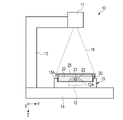
- FIG. 1 shows an example of an imaging device.
- the imaging device 10 has a light source 11 , an imaging sensor 12 , a support 13 , a base 14 and a stage 15 .
- the light source 11 is, for example, a laser diode.
- the imaging device 10 performs so-called lens-free imaging, in which an observation target is imaged without using an optical lens.
- the light source 11 may be configured by combining a light emitting diode and a pinhole.
- the light source 11 emits radial illumination light 16 toward the stage 15 .
- the illumination light 16 is coherent light.
- the wavelength of the illumination light 16 is 640 nm, 780 nm, or the like.
- the light source 11 is connected to one end of a substantially L-shaped support 13 .
- the other end of the support 13 is connected to the base 14 .
- the base 14 has a flat plate shape, and a stage 15 is provided substantially in the center.
- the stage 15 is provided with a recessed mounting portion 15A on which a culture container 20 for culturing the fertilized egg is mounted.
- the column 13 supports the light source 11 so that the light source 11 faces the imaging surface 12A of the imaging sensor 12 .
- a fertilized egg is an example of an “observation object” according to the technology of the present disclosure.
- the direction in which the light source 11 and the imaging surface 12A face each other is hereinafter referred to as the Z direction.
- the Z direction is also the irradiation direction of the illumination light 16 .
- a direction orthogonal to the Z direction is called an X direction.
- a direction orthogonal to the Z direction and the X direction is called the Y direction.
- the imaging surface 12A is orthogonal to the Z direction and parallel to the X and Y directions.
- the imaging sensor 12 is composed of, for example, a monochrome CMOS (Complementary Metal Oxide Semiconductor) image sensor.
- a culture container 20 is placed on the imaging surface 12A of the imaging sensor 12 .
- the culture container 20 is a shallow cylindrical container and is also called a culture dish.
- Culture vessel 20 is used with lid 25 (see FIG. 2).
- the culture container 20 is transparent and allows the illumination light 16 to pass therethrough.
- the diameter of the culture vessel 20 is about 30 to 60 mm.
- the thickness of the culture vessel 20 is approximately 10 to 20 mm.
- a fertilized egg 21 that has undergone in vitro fertilization is seeded in the culture container 20 .
- In vitro fertilization treatment includes microinsemination treatment performed under a microscope and normal in vitro fertilization treatment in which ovum and sperm are combined in a predetermined container.
- the method of fertilization of the fertilized egg 21 to be cultured does not matter.
- the fertilized egg 21 is, for example, a human fertilized egg.
- the fertilized egg 21 is almost spherical and has a diameter of about 100 to 200 ⁇ m.
- the fertilized egg 21 floats in the culture solution 22 that has been dropped into the culture container 20 .
- the culture medium 22 is covered with oil 23 filled in the culture container 20 .
- the oil 23 suppresses evaporation and pH change of the culture solution 22 .
- the fertilized egg 21 in the divided state is also called an embryo.
- a fertilized egg 21 in the present disclosure includes an embryo.
- FIG. 2 is a side view of the imaging device 10 on which the culture container 20 is placed. As shown in FIG. 2, the fertilized egg 21 is imaged by the imaging device 10 with the culture container 20 covered with the lid 25 .
- the imaging sensor 12 detects the illumination light 16 emitted from the light source 11 and transmitted through the culture container 20 . Specifically, the illumination light 16 is incident on the culture container 20 and diffracted by the fertilized egg 21 , thereby producing an interference fringe image reflecting the shape and internal structure of the fertilized egg 21 . An interference fringe image is also called a hologram image. The imaging sensor 12 captures an interference fringe image generated by the fertilized egg 21 .
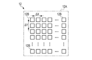
- FIG. 3 shows an example of the configuration of the imaging sensor 12.
- the imaging sensor 12 has a plurality of pixels 12B arranged on an imaging surface 12A.
- the pixel 12B is a photoelectric conversion element that outputs a pixel signal corresponding to the amount of incident light by photoelectrically converting incident light.
- the pixels 12B are arranged at equal pitches along the X and Y directions.
- the arrangement of the pixels 12B is a so-called square arrangement.
- the X direction is a direction perpendicular to the Z direction.
- the Y direction is a direction orthogonal to the X and Z directions.
- the pixels 12B are arranged at a first arrangement pitch ⁇ x in the X direction and arranged at a second arrangement pitch ⁇ y in the Y direction.
- the imaging sensor 12 captures light incident on the imaging surface 12A and outputs image data composed of pixel signals output from each of the pixels 12B.
- FIG. 4 shows how an interference fringe image is generated by irradiating the fertilized egg 21 with the illumination light 16 .
- a part of the illumination light 16 incident on the culture container 20 is diffracted by the fertilized egg 21 . That is, the illumination light 16 is divided into diffracted light 30 diffracted by the fertilized egg 21 and transmitted light 31 not diffracted by the fertilized egg 21 but transmitted through the incubation container 20 .
- the transmitted light 31 is a spherical wave or a plane wave.
- the diffracted light 30 and the transmitted light 31 pass through the bottom surface of the culture container 20 and enter the imaging surface 12A of the imaging sensor 12 .
- the diffracted light 30 and the transmitted light 31 interfere with each other to generate an interference fringe image 33 .
- the interference fringe image 33 is composed of bright portions 36 and dark portions 38 .
- the interference fringe image 33 is illustrated with circular bright portions 36 and dark portions 38 , but the shape of the interference fringe image 33 changes according to the shape and internal structure of the fertilized egg 21 .
- the imaging sensor 12 captures an optical image including the interference fringe image 33 formed on the imaging surface 12A and outputs image data including the interference fringe image 33 .
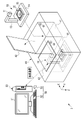
- FIG. 5 shows an example of the configuration of an imaging system.
- the imaging system 2 includes an imaging device 10 , an incubator 40 and an information processing device 50 .
- the incubator 40 is a multi-room incubator for fertilized eggs and is also called an embryo culture device.
- the fertilized egg 21 is cultured within the incubator 40 for a predetermined period (for example, seven days).
- the incubator 40 has a plurality of culture chambers 41, unlike a general incubator for culturing cells other than fertilized eggs. This is because the imaging device 10 is accommodated in each of the culture chambers 41 so that the fertilized egg 21 is managed individually so as not to be mistaken for someone else's fertilized egg 21 .
- the incubation room 41 is also referred to as an incubation chamber. Although two culture chambers 41 are provided in the incubator 40 shown in FIG. 5, the number of culture chambers 41 is not limited to this and can be changed as appropriate.
- Each of the culture chambers 41 is provided with an openable lid 42 .
- the incubator 40 is provided with a switch 43 for opening and closing the lid 42 for each culture chamber 41 .
- the lid 42 is opened and closed by a driving mechanism (not shown).
- the lid 42 may be configured to be manually opened and closed.
- the incubation chamber 41 is kept airtight when the lid 42 is closed.
- a mixed gas obtained by mixing carbon dioxide (CO 2 ) gas and nitrogen (N 2 ) gas with outside air (air) from an external gas cylinder (not shown) is passed through a HEPA filter (High Efficiency Particulate Air Filter). supplied via Heaters (not shown) are provided on the side and bottom surfaces of the culture chamber 41 .
- the incubation chamber 41 is controlled so that the concentration, temperature, and humidity of the mixed gas are kept constant, thereby maintaining a constant culture environment.
- the imaging device 10 has a size that allows it to be taken in and out of the culture room 41 . As shown in FIG. 5, one imaging device 10 is inserted into one incubation chamber 41 . That is, the lid 42 can be closed while the imaging device 10 with the culture container 20 placed thereon is inserted into the culture chamber 41 . As a result, while culturing the fertilized egg 21 in the culture chamber 41 , the image of the fertilized egg 21 can be captured by the imaging device 10 without removing the culture container 20 from the culture chamber 41 .
- the information processing device 50 is, for example, a desktop personal computer.
- a display 51 , a keyboard 52 , a mouse 53 and the like are connected to the information processing device 50 .
- the keyboard 52 and mouse 53 constitute an input device 54 for the user to enter information.
- the input device 54 also includes a touch panel and the like.
- the information processing device 50 exchanges data with the imaging devices 10 accommodated in each incubation room 41 by wireless communication.
- the imaging device 10 performs imaging periodically (for example, every 5 to 15 minutes).
- the information processing device 50 periodically receives image data including the interference fringe image 33 (see FIG. 4) from the imaging device 10, performs reconstruction processing based on the received image data, and reproduces the reconstruction generated by the reconstruction processing. View the composition image.
- a reconstructed image is also called a tomographic image.
- FIG. 6 shows an example of the internal configuration of the imaging device 10 and the information processing device 50.
- the imaging device 10 includes a processor 60, a storage device 61, a communication unit 62, a power supply unit 63, and a battery 64 in addition to the light source 11 and the imaging sensor 12. These are connected via a bus line 65. are interconnected.
- the processor 60 is, for example, an FPGA (Field Programmable Gate Array), and controls the operation of each unit in the imaging device 10.
- the storage device 61 is RAM (Random Access Memory), flash memory, or the like. The storage device 61 stores image data generated by the imaging device 10 and various data.
- the communication unit 62 performs wireless communication with the information processing device 50 .
- Processor 60 transmits image data to information processing device 50 via communication unit 62 .
- the battery 64 is a secondary battery such as a lithium polymer battery.
- the power supply unit 63 includes a power supply circuit and a charging control circuit.
- the power supply unit 63 supplies power supplied from the battery 64 to the processor 60 and the like. Further, the power supply unit 63 controls charging of the battery 64 with electric power supplied from the outside. Note that the power supply unit 63 may be configured to wirelessly charge the battery 64 .
- the information processing device 50 includes a processor 55 , a storage device 56 and a communication section 57 , which are interconnected via a bus line 58 . Also, the display 51 and the input device 54 are connected to the bus line 58 .
- the processor 55 is composed of, for example, a CPU (Central Processing Unit), and implements various functions by reading the operating program 56A and various data stored in the storage device 56 and executing the processes.
- a CPU Central Processing Unit
- the storage device 56 includes, for example, RAM, ROM (Read Only Memory), or a storage device.
- RAM is, for example, a volatile memory used as a work area or the like.
- the ROM is a nonvolatile memory such as a flash memory that holds the operating program 56A and various data, for example.
- the storage device is, for example, a HDD (Hard Disk Drive) or an SSD (Solid State Drive).
- the storage stores an OS (Operating System), application programs, image data, various data, and the like.
- the communication unit 57 performs wireless communication with the communication unit 62 of the imaging device 10 .
- the processor 55 receives image data transmitted from the imaging device 10 via the communication section 57 .
- the processor 55 also transmits a control signal for controlling imaging to the imaging device 10 via the communication unit 57 .
- the display 51 displays various screens.
- the information processing apparatus 50 receives input of operation instructions from the input device 54 through various screens.
- FIG. 7 shows an example of the functional configuration of the information processing device 50.
- the functions of information processing device 50 are realized by processor 55 executing processing based on operation program 56A.
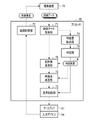
- the processor 55 includes an imaging control section 70 , an image data acquisition section 71 , a reconstruction processing section 72 , a display control section 73 , a feature quantity extraction section 74 and a determination section 75 .
- the imaging control unit 70 controls the operation of the imaging device 10 . Specifically, the imaging control unit 70 controls the operation of generating the illumination light 16 by the light source 11 and the imaging operation of the imaging sensor 12 by transmitting control signals to the imaging device 10 .
- the operation of generating the illumination light 16 by the light source 11 and the imaging operation of the imaging sensor 12 are collectively referred to as the imaging operation of the imaging device 10 .
- the imaging control unit 70 causes the imaging device 10 to start imaging operation based on the operation signal input from the input device 54 .
- the image data acquisition unit 71 acquires generated image data transmitted from the imaging device 10 after the imaging device 10 has captured an image of the fertilized egg 21 in the culture container 20 .
- the image data acquisition unit 71 supplies the acquired image data to the reconstruction processing unit 72 .
- the reconstruction processing unit 72 generates a reconstructed image by performing calculations based on the image data. For example, as shown in FIG. 8, the reconstruction processing unit 72 changes the reconstruction position P by a constant value in the Z direction, and generates a reconstructed image each time the reconstruction position P is changed.
- the reconstruction position P is a position represented by a distance d from the imaging surface 12A of the imaging sensor 12 toward the light source 11 (so-called depth position).
- the reconstruction position P will also be referred to as the focal position.
- the reconstruction processing unit 72 performs reconstruction processing based on, for example, the Fresnel transform equations represented by the following equations (1) to (3).
- I(x, y) represents image data.
- x represents the coordinate in the X direction of the pixel 12B (see FIG. 3) of the image sensor 12;
- y represents the coordinate of the pixel 12B in the Y direction.
- ⁇ x is the aforementioned first array pitch
- ⁇ y is the aforementioned second array pitch (see FIG. 3).
- ⁇ is the wavelength of the illumination light 16 .
- ⁇ (m,n) is a complex amplitude image obtained by Fresnel transforming the interference fringe image included in the image data.
- Nx represents the number of pixels in the X direction of the image data.
- Ny represents the number of pixels in the Y direction of the image data.
- a 0 (m,n) is an intensity distribution image representing intensity components of the complex amplitude image ⁇ (m,n).
- ⁇ 0 (m,n) is a phase distribution image representing the phase component of the complex amplitude image ⁇ (m,n).
- the reconstruction processing unit 72 obtains a complex amplitude image ⁇ (m,n) based on equation (1), and applies the obtained complex amplitude image ⁇ (m,n) to equation (2) or equation (3). By doing so, an intensity distribution image A 0 (m, n) or a phase distribution image ⁇ 0 (m, n) is obtained.
- the reconstruction processing unit 72 obtains one of the intensity distribution image A 0 (m, n) and the phase distribution image ⁇ 0 (m, n) and outputs it as a reconstructed image.
- the reconstruction processing unit 72 outputs the phase distribution image ⁇ 0 (m, n) as a reconstructed image.
- the phase distribution image ⁇ 0 (m, n) is an image representing the refractive index distribution of the observed object. Since the fertilized egg 21, which is the object to be observed in this embodiment, is translucent, most of the illumination light 16 is transmitted or diffracted without being absorbed by the fertilized egg 21, so the intensity distribution is hardly any image appears in Therefore, in this embodiment, it is preferable to use the phase distribution image ⁇ 0 (m, n) as the reconstructed image.
- the reconstruction processing unit 72 is not limited to the method using the Fresnel transform formula, and may perform the reconstruction processing using the Fourier iterative phase retrieval method or the like.
- the display control unit 73 causes the display 51 to display the reconstructed image generated by the reconstruction processing unit 72 .
- the display 51 may display a reconstructed image at one focus position, or may display reconstructed images at a plurality of focus positions. Also, the focus position of the reconstructed image displayed on the display 51 may be set or selected by the user operating the input device 54 .
- the fertilized egg 21 has a thickness of about 100 to 200 ⁇ m and floats in the culture solution 22, it is difficult to adjust the focal position for the pronucleus inside the fertilized egg 21 in conventional microscopic observation. For this reason, for example, in the conventional technique described in Japanese Patent Application Laid-Open No. 2018-093795, a plurality of images with different focal positions are captured. On the other hand, in the lens-free imaging of the present disclosure, it is possible to generate a reconstructed image at an arbitrary focal position based on image data obtained by one imaging.
- the feature amount extraction unit 74 extracts image feature amounts from the image data acquired by the image data acquisition unit 71 .
- the feature quantity extraction unit 74 searches for the interference fringe image 33 from the image data by performing template matching using the interference fringe image 33 shown in FIG. 4 as a template.
- the feature amount extraction unit 74 outputs a correlation value representing the degree of matching between the image included in the image data and the interference fringe image 33 to the determination unit 75 as a feature amount.
- the determination unit 75 determines the quality of the interference fringe image included in the image data acquired by the image data acquisition unit 71 based on the feature amount input from the feature amount extraction unit 74 .
- the “quality” corresponds to the degree of similarity with the interference fringe image 33 obtained by imaging the fertilized egg 21 .
- the quality of the interference fringes to be determined is higher as the degree of similarity with the interference fringe image 33 of the fertilized egg 21 is higher.
- the determination unit 75 determines the quality of the interference fringe image based on whether the correlation value is equal to or greater than a reference value.
- the determination unit 75 outputs the determination result R of the quality of the interference fringe image to the reconstruction processing unit 72 and the display control unit 73 .
- the determination result R includes information indicating whether or not to continue the reconstruction processing by the reconstruction processing unit 72 according to the quality of the interference fringe image.
- the determination result R may be a permission signal R1 that permits the execution of reconstruction processing in response to the fact that the quality of the interference fringe image is above a certain level (that is, the correlation value is above the reference value), or a permission signal R1 that permits the execution of the reconstruction process if the quality of the interference fringe image is above a certain level.
- a disallowing signal R2 is included that disallows execution of the reconstruction process in response to being less than (ie, the correlation value is less than the reference value).
- the reconstruction processing unit 72 determines whether the reconstruction processing can be executed. If the determination result R includes the permission signal R1, the reconstruction processing unit 72 executes the reconstruction processing. Further, when the determination result R includes the disallowing signal R2, the reconstruction processing unit 72 does not perform the reconstruction processing.
- the display control unit 73 causes the display 51 to display a message based on the determination result R input from the determination unit 75 .
- the display control unit 73 causes the display 51 to display a message indicating that the reconstruction process is not executed due to the low quality of the interference fringe image.
- the display control unit 73 preferably causes the display 51 to display a message prompting the user to perform re-imaging.
- the display control unit 73 instructs the user to It is preferable to display a message on the display 51 urging the user to confirm the condition of the object and then retake the image.
- FIG. 9 to 11 show examples of judgment results R obtained by judging the quality of the interference fringe image.
- FIG. 9 shows an example of image data generated by the imaging device 10 when water droplets 80 adhere to the lid 25 .
- the illumination light 16 is incident on the water droplets 80 and diffuses into diffused light.
- the interference fringe image 33 does not appear in the image data D, and diffused light that is diffused as a whole is imaged.
- the correlation value calculated by template matching as the feature amount extracted by the feature amount extraction unit 74 is less than the reference value.
- the determination unit 75 determines that the quality of the interference fringe image is below a certain level, and outputs the determination result R including the disapproval signal R2 to the reconstruction processing unit 72 and the display control unit 73 .
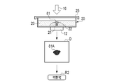
- FIG. 10 shows an example of image data generated by the imaging device 10 when air bubbles 81 are mixed in the culture solution 22.
- FIG. 10 when air bubbles 81 are present in the culture solution 22, the difference in refractive index between the culture solution 22 and the air bubbles 81 (that is, air) causes light refraction.
- the interference fringe image 33 does not appear in the image data D, and only the shadow 81A of the air bubble 81 is imaged.
- the correlation value calculated by template matching as the feature amount extracted by the feature amount extraction unit 74 is less than the reference value.
- the determination unit 75 determines that the quality of the interference fringe image is below a certain level, and outputs the determination result R including the disapproval signal R2 to the reconstruction processing unit 72 and the display control unit 73 .
- FIG. 11 shows an example of image data generated by the imaging device 10 when water droplets are not attached to the lid 25 and air bubbles are not mixed into the culture solution 22 .
- the image data D includes an interference fringe image 33 based on the fertilized egg 21 when the image of the fertilized egg 21 is satisfactorily performed.
- the correlation value calculated by template matching as the feature amount extracted by the feature amount extraction unit 74 is equal to or greater than the reference value.
- the determination unit 75 determines that the quality of the interference fringe image is above a certain level, and outputs the determination result R including the permission signal R1 to the reconstruction processing unit 72 and the display control unit 73 .
- the determination unit 75 determines the presence or absence of the interference fringe image 33 in the image data, and outputs the determination result R according to the presence or absence of the interference fringe image 33. That is, in this embodiment, whether or not the reconstruction process can be executed is determined based on the presence or absence of the interference fringe image 33 .
- the user places the culture container 20 on the stage 15 of the imaging device 10 and then inserts the imaging device 10 into the culture chamber 41 of the incubator 40 .
- At least one imaging device 10 may be inserted into the plurality of culture chambers 41 .
- the user closes the lid 42 of the culture chamber 41 and causes the incubator 40 to start culturing.
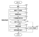
- the imaging device 10 images the fertilized egg 21 in the incubation container 20 under the control of the information processing device 50 (step S10).
- the imaging device 10 transmits image data generated by performing an imaging operation to the information processing device 50 .
- the information processing device 50 acquires the image data transmitted from the imaging device 10 by the image data acquisition unit 71 (step S11).
- the feature quantity extraction unit 74 of the information processing device 50 extracts a feature quantity from the image data acquired by the image data acquisition unit 71 (step S12). For example, the feature quantity extraction unit 74 extracts a correlation value representing the degree of matching with the interference fringe image 33 as a feature quantity by template matching.
- the determination unit 75 determines the quality of the interference fringe image included in the image data based on the feature amount extracted by the feature amount extraction unit 74, and outputs the determination result R to the reconstruction processing unit 72 and the display control unit 73. (step S13).
- a permission signal R1 is output as the determination result R from the determination unit 75 to the reconstruction processing unit 72 and the display control unit 73.
- the reconstruction processing unit 72 generates a reconstructed image by performing reconstruction processing based on the image data acquired by the image data acquisition unit 71 (step S15).
- the display control unit 73 causes the display 51 to display the reconstructed image generated by the reconstruction processing unit 72 (step S16).
- step S14 when the quality of the interference fringe image is less than a certain value (step S14: NO), a disapproval signal R2 is output from the determination unit 75 to the reconstruction processing unit 72 and the display control unit 73 as the determination result R. .
- the reconstruction processing unit 72 does not perform reconstruction processing.
- the display control unit 73 causes the display 51 to display a message indicating that the reconstruction process is not executed due to the low quality of the interference fringe image (step S17).
- the quality of the interference fringe image included in the image data obtained by the imaging device 10 is determined. Do not perform reconstruction processing on Therefore, when the quality of the interference fringe image is low, the user does not need to wait for the completion of the reconstruction process, and after confirming whether foreign matter is attached to or mixed with the culture container 20 or the lid 25, Early retakes can be performed. Therefore, observation efficiency of the observed object is improved.
- the feature quantity extraction unit 74 extracts the correlation value representing the degree of matching with the interference fringe image 33 as the feature quantity by template matching. You may In this case, for example, the feature amount extraction unit 74 extracts frequency characteristics by performing frequency analysis using Fourier transform or the like on the image data.
- the determination unit 75 determines the quality of the interference fringe image based on the frequency characteristic as the feature amount. The determining unit 75 determines that the closer the frequency characteristic extracted from the image data D to be determined to the frequency characteristic of the interference fringe image 33 of the fertilized egg 21, the higher the quality.
- the quality of the interference fringe image is determined based on a plurality of image data obtained by imaging a plurality of times.
- the light source 11 may be a laser light source in which a plurality of light emitting points (for example, 36 light emitting points) are arranged in a two-dimensional array.
- a vertical cavity surface emitting laser (Vertical Cavity Surface Emitting Laser) can be used.
- a high-resolution interference fringe image (so-called super-resolution interference fringe image) is included by synthesizing a plurality of image data obtained by performing an imaging operation of the imaging sensor 12 while sequentially emitting light from a plurality of light-emitting points. Image data is obtained. By reconstructing this image data, a reconstructed image with high image quality can be obtained.
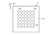
- FIG. 13 shows the configuration of the light emitting surface 11A of the light source 11 included in the imaging device 10 according to the second embodiment.
- the light emitting surface 11A is arranged at a position facing the imaging sensor 12 .
- a plurality of light emitting points 11B are arranged in a two-dimensional array on the light emitting surface 11A.
- the arrangement pitch of the light emitting points 11B is about 10 ⁇ m to 100 ⁇ m.
- Each of the light emitting points 11B is selected in order to emit illumination light 16.
- the light emission time interval of the plurality of light emission points 11B is several milliseconds.
- the arrangement pitch of the light emitting points 11B only needs to be different from the arrangement pitch of the pixels 12B (the first arrangement pitch ⁇ x and the second arrangement pitch ⁇ y), and does not necessarily have to be smaller than the arrangement pitch of the pixels 12B. For example, even if the light emitting point 11B is located directly above the adjacent pixel 12B, the array pitch of the light emitting point 11B does not have to match the array pitch of the pixels 12B. In this case, since different positions on the pixels 12B are illuminated with the illumination light 16, when combining a plurality of image data, different pixels 12B that are directly below the respective light emitting points 11B and illuminated with the illumination light 16 can be selected. It is possible to generate image data including a super-resolution interference fringe image by regarding them as the same pixel and aligning them with an accuracy of one pixel or less.
- the light-emitting points 11B are arranged in a 6 ⁇ 6 square, and 36 light-emitting points 11B are provided on the light-emitting surface 11A.
- the imaging sensor 12 performs an imaging operation and generates image data each time each of the light emitting points 11B emits light.
- the imaging device 10 transmits to the information processing device 50 a plurality of image data obtained by the imaging sensor 12 performing imaging a plurality of times.
- FIG. 14 shows an example of the functional configuration of an information processing device 50 according to the second embodiment.
- the processor 55 includes an imaging control unit 70, an image data acquisition unit 71, a reconstruction processing unit 72, a display control unit 73, a feature amount extraction unit 74, and a determination unit 75.
- a super-resolution processing unit 76 is configured.
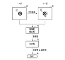
- FIG. 15 schematically shows super-resolution processing by the super-resolution processing unit 76.
- the plurality of light emitting points 11B provided on the light source 11 sequentially emit light one by one according to the control from the imaging control section 70.
- t represents time.
- the interference fringe image 33 included in the image data D obtained by the imaging sensor 12 capturing images at each time t in the time series t t1, t2, t3 .
- the position in D is shifted.
- the super-resolution processing unit 76 aligns and synthesizes a plurality of image data D to generate image data DS including a super-resolution interference fringe image 33S.
- the super-resolution processing unit 76 outputs the generated image data DS to the reconstruction processing unit 72 .
- the feature quantity extraction unit 74 calculates correlation values of successive interference fringe images in time series as feature quantities for each of the plurality of image data D.
- FIG. The determination unit 75 determines whether or not the correlation value is greater than or equal to the reference value. When the correlation value is equal to or greater than the reference value, the determination unit 75 determines that the quality of the interference fringe image is equal to or higher than a certain level, and outputs a determination result R including the permission signal R1. Further, when the correlation value is less than the reference value, the determination section 75 determines that the quality of the interference fringe image is less than a certain level, and outputs a determination result R including a disallowance signal R2.
- the feature quantity extraction unit 74 is not limited to the correlation value of the time-series continuous interference fringe images, and may calculate the difference value of the time-series continuous interference fringe images as the feature quantity. Even when the fertilized egg 21 is translated, the difference value can be calculated by aligning the successive interference fringe images in time series and taking the difference. In other words, the feature amount extraction unit 74 may calculate the feature amount based on the temporal change of the interference fringe images that are continuous in time series.
- 16 and 17 show an example of calculating the correlation value between the image data D obtained at time t1 and the image data D obtained at time t2.
- FIG. 16 shows an example in which the pattern of the interference fringe image 33 in the image data D changes due to the rotation of the fertilized egg 21 between time t1 and time t2. Since the fertilized egg 21 floats in the culture solution 22, rotation is likely to occur. When the fertilized egg 21 rotates, the position of the pronucleus inside the fertilized egg 21 changes, so that the pattern of the interference fringe image 33 changes. In this way, when the pattern of the interference fringe image 33 changes due to the rotation of the fertilized egg 21, the correlation value calculated by the feature amount extraction unit 74 is less than the reference value. In this case, the determination unit 75 determines that the quality of the interference fringe image is less than a certain level, and outputs the determination result R including the non-permission signal R2.
- FIG. 17 shows an example in which the interference fringe image 33 in the image data D moves linearly due to parallel movement of the fertilized egg 21 between time t1 and time t2.
- the pattern of the interference fringe image 33 does not change.
- the correlation value calculated by the feature quantity extraction unit 74 is equal to or greater than the reference value.
- the determination unit 75 determines that the quality of the interference fringe image is above a certain level, and outputs the determination result R including the permission signal R1.
- the super-resolution processing unit 76 can align the interference fringe image 33, so the image quality of the image data DS generated by the super-resolution processing unit 76 is does not decrease.
- the pattern of the interference fringe image 33 may be generated by the cell division of the fertilized egg 21 in addition to the rotation of the fertilized egg 21 .
- the temperature changes greatly, so that the fertilized egg 21 moves greatly, and the pattern of the interference fringe image 33 may change.
- whether or not super-resolution processing and reconstruction processing can be executed is determined based on the temporal change in the pattern of the interference fringe image 33 .
- imaging is performed a plurality of times while changing the light emitting point 11B of the light source 11 (step S20).
- the imaging device 10 transmits to the information processing device 50 a plurality of image data generated by performing imaging operations a plurality of times.
- the information processing device 50 uses the image data acquisition unit 71 to acquire a plurality of image data transmitted from the imaging device 10 (step S21).
- the feature amount extraction unit 74 of the information processing device 50 extracts feature amounts from the plurality of image data acquired by the image data acquisition unit 71 (step S22).
- the correlation value of the interference fringe images that are continuous in time series is calculated as the feature amount for each of the plurality of image data.
- the determination unit 75 determines the quality of the interference fringe image included in the image data based on the feature amount extracted by the feature amount extraction unit 74, and the determination result R is transferred to the super-resolution processing unit 76 for reconstruction processing. It outputs to the unit 72 and the display control unit 73 (step S23). In this embodiment, the determination unit 75 determines that the quality of the interference fringe image is less than a certain level when at least one of the plurality of correlation values calculated by the feature amount extraction unit 74 is less than the reference value. Then, the judgment result R including the disallowing signal R2 is output.
- the determination unit 75 determines that the quality of the interference fringe image is equal to or higher than a certain value, and outputs the permission signal R1. Output the determination result R including.
- the super-resolution processing unit 76 When the quality of the interference fringe image is above a certain level (step S24: YES), the super-resolution processing unit 76 performs super-resolution processing based on the plurality of image data acquired by the image data acquiring unit 71. generates image data including a super-resolution interference fringe image (step S25).
- the reconstruction processing unit 72 generates a reconstructed image by performing reconstruction processing based on the image data generated by the super-resolution processing unit 76 (step S26).
- the display control unit 73 causes the display 51 to display the reconstructed image generated by the reconstruction processing unit 72 (step S27).
- step S24 when the quality of the interference fringe image is less than a certain value (step S24: NO), the super-resolution processing unit 76 does not execute super-resolution processing, and the reconstruction processing unit 72 executes reconstruction processing. do not do.
- the display control unit 73 causes the display 51 to display a message indicating that the reconstruction process is not executed due to the low quality of the interference fringe image (step S28).
- the quality of the interference fringe image is determined based on the time change of the interference fringe image included in the plurality of image data obtained by the imaging device 10. and do not perform super-resolution processing and reconstruction processing if the quality is less than a certain value. Therefore, when the quality of the interference fringe image is low, the user does not need to wait for the super-resolution processing and the reconstruction processing to be completed, and can quickly perform re-imaging after confirming the state of the fertilized egg 21. can be done. Therefore, observation efficiency of the observed object is improved.
- the feature quantity extraction unit 74 and the determination unit 75 perform processing after the imaging device 10 has generated a plurality of pieces of image data through a plurality of imaging operations.
- the processing may be performed each time an imaging operation is performed and one piece of image data is generated. That is, it may be determined whether or not to continue the imaging operation based on the determination result of the quality of the interference fringe image while the imaging device 10 is performing imaging a plurality of times. In this case, the imaging operation is stopped when it is determined that the quality of the interference fringe image is below a certain level.
- the interference fringe image it may be determined whether to continue the imaging operation and reconstruction processing based on the determination result of the quality of the image. In this case, if it is determined that the quality of the interference fringe image is below a certain level, the imaging operation and the reconstruction process are stopped.
- the imaging device 10 and the information processing device 50 are separate devices, but the imaging device 10 and the information processing device 50 may be integrated into one device. . Furthermore, the imaging device 10, the information processing device 50, and the incubator 40 may be integrally configured as one device.
- the observation object is the fertilized egg, but the observation object may be floating cells other than the fertilized egg.
- Suspended cells are cells that float in a culture medium. Floating cells include, in addition to fertilized eggs, CHO (Chinese Hamster Ovary) cells used for antibody production.
- the imaging system 2 relates to a technique called lens-free imaging in which the imaging device 10 is not equipped with an optical lens.
- the technology of the present disclosure is applicable to digital holography in general (for example, when using reference light).
- the hardware configuration of the computer that constitutes the information processing device 50 can be configured with a plurality of computers separated as hardware for the purpose of improving processing capability and reliability.
- the hardware configuration of the computer of the information processing device 50 can be appropriately changed according to required performance such as processing power, safety, and reliability.
- application programs such as the operating program 56A can be duplicated or distributed and stored in multiple storage devices for the purpose of ensuring safety and reliability. .
- the imaging control unit 70 the image data acquisition unit 71, the reconstruction processing unit 72, the display control unit 73, the feature amount extraction unit 74, the determination unit 75, and the super-resolution processing unit 76.
- a processing unit processing unit
- various types of processors shown below can be used.
- the various processors include, as described above, a CPU, which is a general-purpose processor that executes software (operation program 56A) and functions as various processing units, as well as FPGAs and the like whose circuit configuration can be changed after manufacture.
- Programmable Logic Device which is a processor, ASIC (Application Specific Integrated Circuit), etc. Includes a dedicated electric circuit, which is a processor with a circuit configuration specially designed to execute specific processing. .
- One processing unit may be configured with one of these various processors, or a combination of two or more processors of the same or different type (for example, a combination of a plurality of FPGAs and/or a CPU and combination with FPGA). Also, a plurality of processing units may be configured by one processor.
- a single processor is configured by combining one or more CPUs and software.
- a processor functions as multiple processing units.
- SoC System On Chip
- a processor that realizes the functions of the entire system including multiple processing units with a single IC (Integrated Circuit) chip. be.
- the various processing units are configured using one or more of the above various processors as a hardware structure.
Landscapes
- Engineering & Computer Science (AREA)
- Physics & Mathematics (AREA)
- General Physics & Mathematics (AREA)
- Health & Medical Sciences (AREA)
- Chemical & Material Sciences (AREA)
- Theoretical Computer Science (AREA)
- Life Sciences & Earth Sciences (AREA)
- General Health & Medical Sciences (AREA)
- Bioinformatics & Cheminformatics (AREA)
- Organic Chemistry (AREA)
- Wood Science & Technology (AREA)
- Analytical Chemistry (AREA)
- Biotechnology (AREA)
- Biochemistry (AREA)
- Zoology (AREA)
- Medical Informatics (AREA)
- Nuclear Medicine, Radiotherapy & Molecular Imaging (AREA)
- Computer Vision & Pattern Recognition (AREA)
- Quality & Reliability (AREA)
- Radiology & Medical Imaging (AREA)
- General Engineering & Computer Science (AREA)
- Medicinal Chemistry (AREA)
- Pathology (AREA)
- Genetics & Genomics (AREA)
- Sustainable Development (AREA)
- Biomedical Technology (AREA)
- Microbiology (AREA)
- Immunology (AREA)
- Investigating Or Analysing Materials By Optical Means (AREA)
Abstract
An information processing device for processing image data acquired from an image capturing device that includes a light source and an image capturing sensor and generates image data by capturing an interference fringe image resulting from irradiation of an object to be observed with illumination light, said information processing device including a processor, wherein the processor extracts a feature amount from the image data and determines, on the basis of the feature amount, the quality of the interference fringe image contained in the image data.
Description
本開示の技術は、情報処理装置、情報処理方法、及びプログラムに関する。
The technology of the present disclosure relates to an information processing device, an information processing method, and a program.
従来、細胞等の観察には位相差顕微鏡等の顕微鏡が用いられていたが、観察対象物の撮像時に焦点合わせを行う必要があった。このため、近年は、観察対象物の撮像時に焦点合わせが不要なレンズフリーのデジタルホログラフィが用いられつつある(例えば、国際公開第2018/158947号参照)。
Conventionally, microscopes such as phase-contrast microscopes were used to observe cells, etc., but it was necessary to focus when imaging the observation target. For this reason, in recent years, lens-free digital holography, which does not require focusing when capturing an image of an observation target, is being used (see, for example, International Publication No. 2018/158947).
デジタルホログラフィでは、レーザ光等のコヒーレントな光を観察対象物に照射することにより生じる干渉縞像を撮像し、撮像により得られた干渉縞像を再構成することにより、任意の焦点位置における再構成画像(いわゆる断層画像)を生成することができる。
In digital holography, an interference fringe image generated by irradiating an observation object with coherent light such as a laser beam is imaged, and the interference fringe image obtained by imaging is reconstructed at an arbitrary focal position. Images (so-called tomographic images) can be generated.
しかしながら、デジタルホログラフィでは、レーザ光等の光を観察対象物に照射することにより生じる干渉縞画像を用いることから、光源と観察対象物との間に気泡などの異物が存在する場合に、異物の屈折率等の影響により干渉縞像が生成されず、観察対象物を表す再構成画像が得られないことがある。
However, digital holography uses an interference fringe image generated by irradiating an object to be observed with light such as a laser beam. An interference fringe image may not be generated due to the influence of the refractive index, etc., and a reconstructed image representing the observed object may not be obtained.
再構成処理は時間がかかるため、再構成処理が得られた後に干渉縞像が得られていないことが判明した場合に、再度観察対象物の撮影を行うと、無駄に時間が費やされることになり、観察効率が低下する。
Since the reconstruction process takes time, if it is found that the interference fringe image has not been obtained after the reconstruction process has been completed, time will be wasted if the object to be observed is photographed again. and the observation efficiency decreases.
本開示の技術は、観察効率の向上を図ることを可能とする情報処理装置、情報処理方法、及びプログラムを提供することを目的とする。
An object of the technology of the present disclosure is to provide an information processing device, an information processing method, and a program capable of improving observation efficiency.
上記目的を達成するために、本開示の情報処理装置は、光源及び撮像センサを備え、観察対象物に照明光を照射することにより生じる干渉縞像を撮像して画像データを生成する撮像装置から画像データを取得して処理を行う情報処理装置であって、プロセッサを備え、プロセッサは、画像データから特徴量を抽出し、特徴量に基づいて画像データに含まれる干渉縞像の質を判定する。
In order to achieve the above object, an information processing apparatus of the present disclosure includes an imaging device that includes a light source and an imaging sensor, and that captures an interference fringe image generated by irradiating an observation target with illumination light to generate image data. An information processing apparatus for acquiring and processing image data, comprising a processor, wherein the processor extracts a feature amount from the image data and determines the quality of an interference fringe image included in the image data based on the feature amount. .
プロセッサは、画像データに基づいて再構成処理を実行することが可能であり、干渉縞像の質の判定結果に基づいて、再構成処理の実行の可否を判断することが好ましい。
The processor is capable of executing reconstruction processing based on the image data, and preferably determines whether or not the reconstruction processing can be executed based on the determination result of the quality of the interference fringe image.
プロセッサは、画像データに基づくテンプレートマッチング又は周波数解析により特徴量を抽出することが好ましい。
The processor preferably extracts feature amounts by template matching or frequency analysis based on image data.
プロセッサは、特徴量に基づいて画像データ内における干渉縞像の有無又は干渉縞像の変化について判定することが好ましい。
It is preferable that the processor determines the presence or absence of an interference fringe image in the image data or a change in the interference fringe image based on the feature amount.
光源は複数の発光点を有し、撮像装置は、発光点を順に発光させながら複数回の撮像動作を行うことにより、複数の画像データを生成することが好ましい。
It is preferable that the light source has a plurality of light emitting points, and the imaging device generates a plurality of image data by performing a plurality of imaging operations while sequentially causing the light emitting points to emit light.
プロセッサは、複数の画像データに含まれる時系列的に連続する干渉縞像の時間変化に基づいて特徴量を算出することが好ましい。
It is preferable that the processor calculates the feature quantity based on the temporal change of the interference fringe images that are consecutive in time series and included in the plurality of image data.
前記プロセッサは、時系列的に連続する干渉縞像の相関値又は差分値を特徴量として算出することが好ましい。
It is preferable that the processor calculates a correlation value or a difference value of the interference fringe images consecutive in time series as the feature amount.
プロセッサは、複数の画像データに基づいて高解像度の画像データを生成する超解像処理と、超解像処理により生成された画像データに基づく再構成処理とを実行することが可能であり、干渉縞像の質の判定結果に基づいて、超解像処理及び再構成処理の実行の可否を判断することが好ましい。
The processor is capable of executing super-resolution processing for generating high-resolution image data based on a plurality of image data, and reconstruction processing based on the image data generated by the super-resolution processing, and interference It is preferable to determine whether super-resolution processing and reconstruction processing can be performed based on the determination result of the fringe image quality.
観察対象物は、受精卵、又は受精卵以外の浮遊細胞であることが好ましい。
The object to be observed is preferably a fertilized egg or a floating cell other than a fertilized egg.
本開示の情報処理方法は、光源及び撮像センサを備え、観察対象物に照明光を照射することにより生じる干渉縞像を撮像して画像データを生成する撮像装置から画像データを取得して処理を行う情報処理方法であって、画像データから特徴量を抽出し、特徴量に基づいて画像データに含まれる干渉縞像の質を判定する。
The information processing method of the present disclosure acquires image data from an imaging device that includes a light source and an imaging sensor and generates image data by imaging an interference fringe image generated by irradiating an observation object with illumination light, and performs processing. In this information processing method, a feature amount is extracted from image data, and the quality of an interference fringe image included in the image data is determined based on the feature amount.
本開示のプログラムは、光源及び撮像センサを備え、観察対象物に照明光を照射することにより生じる干渉縞像を撮像して画像データを生成する撮像装置から画像データを取得して行う処理をコンピュータに実行させるプログラムであって、画像データから特徴量を抽出すること、特徴量に基づいて画像データに含まれる干渉縞像の質を判定することを含む処理をコンピュータに実行させる。
The program of the present disclosure is provided with a light source and an imaging sensor, and acquires image data from an imaging device that captures an interference fringe image generated by irradiating an observation object with illumination light and generates image data. A program to be executed by a computer, which causes a computer to execute processing including extracting a feature amount from image data and determining the quality of an interference fringe image included in the image data based on the feature amount.
本開示の技術によれば、観察効率の向上を図ることを可能とする情報処理装置、情報処理方法、及びプログラムを提供することができる。
According to the technology of the present disclosure, it is possible to provide an information processing device, an information processing method, and a program that make it possible to improve observation efficiency.
添付図面に従って本開示の技術に係る実施形態の一例について説明する。
An example of an embodiment according to the technology of the present disclosure will be described with reference to the accompanying drawings.
[第1実施形態]
図1は、撮像装置の一例を示す。撮像装置10は、光源11、撮像センサ12、支柱13、基台14、及びステージ15を有する。光源11は、例えばレーザーダイオードである。撮像装置10は、光学レンズを用いずに観察対象物を撮像する、いわゆるレンズフリーイメージングを行う。 [First embodiment]
FIG. 1 shows an example of an imaging device. Theimaging device 10 has a light source 11 , an imaging sensor 12 , a support 13 , a base 14 and a stage 15 . The light source 11 is, for example, a laser diode. The imaging device 10 performs so-called lens-free imaging, in which an observation target is imaged without using an optical lens.
図1は、撮像装置の一例を示す。撮像装置10は、光源11、撮像センサ12、支柱13、基台14、及びステージ15を有する。光源11は、例えばレーザーダイオードである。撮像装置10は、光学レンズを用いずに観察対象物を撮像する、いわゆるレンズフリーイメージングを行う。 [First embodiment]
FIG. 1 shows an example of an imaging device. The
光源11は、発光ダイオードとピンホールとを組み合わせて構成されたものであってもよい。光源11は、放射状の照明光16を、ステージ15に向けて出射する。照明光16は、コヒーレントな光である。照明光16の波長は、640nm、780nm等である。
The light source 11 may be configured by combining a light emitting diode and a pinhole. The light source 11 emits radial illumination light 16 toward the stage 15 . The illumination light 16 is coherent light. The wavelength of the illumination light 16 is 640 nm, 780 nm, or the like.
光源11は、ほぼL字状の支柱13の一端に接続されている。支柱13の他端は、基台14に接続されている。基台14は、平板状であって、ほぼ中央にステージ15が設けられている。ステージ15には、受精卵を培養するための培養容器20が載置される凹状の載置部15Aが設けられている。支柱13は、光源11が撮像センサ12の撮像面12Aに対向するように、光源11を支持している。受精卵は、本開示の技術に係る「観察対象物」の一例である。
The light source 11 is connected to one end of a substantially L-shaped support 13 . The other end of the support 13 is connected to the base 14 . The base 14 has a flat plate shape, and a stage 15 is provided substantially in the center. The stage 15 is provided with a recessed mounting portion 15A on which a culture container 20 for culturing the fertilized egg is mounted. The column 13 supports the light source 11 so that the light source 11 faces the imaging surface 12A of the imaging sensor 12 . A fertilized egg is an example of an “observation object” according to the technology of the present disclosure.
以下、光源11と撮像面12Aとが対向する方向をZ方向という。Z方向は、照明光16の照射方向でもある。また、Z方向に直交する一方向をX方向という。そして、Z方向及びX方向に直交する方向をY方向という。撮像面12Aは、Z方向に直交し、かつX方向及びY方向に平行である。
The direction in which the light source 11 and the imaging surface 12A face each other is hereinafter referred to as the Z direction. The Z direction is also the irradiation direction of the illumination light 16 . A direction orthogonal to the Z direction is called an X direction. A direction orthogonal to the Z direction and the X direction is called the Y direction. The imaging surface 12A is orthogonal to the Z direction and parallel to the X and Y directions.
撮像センサ12は、例えば、モノクロのCMOS(Complementary Metal Oxide Semiconductor)型イメージセンサにより構成されている。撮像センサ12の撮像面12A上に培養容器20が載置される。培養容器20は、円筒状の浅い容器であり、培養ディッシュとも称される。培養容器20は、蓋25(図2参照)とともに用いられる。培養容器20は、透明であり、照明光16を透過させる。なお、培養容器20の直径は、30~60mm程度である。培養容器20の厚みは、10~20mm程度である。
The imaging sensor 12 is composed of, for example, a monochrome CMOS (Complementary Metal Oxide Semiconductor) image sensor. A culture container 20 is placed on the imaging surface 12A of the imaging sensor 12 . The culture container 20 is a shallow cylindrical container and is also called a culture dish. Culture vessel 20 is used with lid 25 (see FIG. 2). The culture container 20 is transparent and allows the illumination light 16 to pass therethrough. Incidentally, the diameter of the culture vessel 20 is about 30 to 60 mm. The thickness of the culture vessel 20 is approximately 10 to 20 mm.
培養容器20には、体外受精の処置がなされた受精卵21が播種されている。体外受精の処置には、顕微鏡下で行なわれる顕微授精による処置と、卵子と精子を所定の容器内で一緒にして行なわれる通常の体外受精による処置とが含まれる。培養する受精卵21の受精の手法は問わない。受精卵21は、例えば、人の受精卵である。受精卵21は、ほぼ球形であって、直径は100~200μm程度である。
A fertilized egg 21 that has undergone in vitro fertilization is seeded in the culture container 20 . In vitro fertilization treatment includes microinsemination treatment performed under a microscope and normal in vitro fertilization treatment in which ovum and sperm are combined in a predetermined container. The method of fertilization of the fertilized egg 21 to be cultured does not matter. The fertilized egg 21 is, for example, a human fertilized egg. The fertilized egg 21 is almost spherical and has a diameter of about 100 to 200 μm.
受精卵21は、培養容器20に滴下された培養液22中に浮遊している。培養液22は、培養容器20に充填されたオイル23で覆われている。オイル23は、培養液22の蒸発及びpHの変化を抑制する。なお、分裂状態にある受精卵21は、胚とも称される。本開示における受精卵21には、胚が含まれる。
The fertilized egg 21 floats in the culture solution 22 that has been dropped into the culture container 20 . The culture medium 22 is covered with oil 23 filled in the culture container 20 . The oil 23 suppresses evaporation and pH change of the culture solution 22 . Note that the fertilized egg 21 in the divided state is also called an embryo. A fertilized egg 21 in the present disclosure includes an embryo.
図2は、培養容器20が載置された撮像装置10の側面図である。図2に示すように、培養容器20に蓋25をかぶせた状態で撮像装置10により受精卵21の撮像が行われる。
FIG. 2 is a side view of the imaging device 10 on which the culture container 20 is placed. As shown in FIG. 2, the fertilized egg 21 is imaged by the imaging device 10 with the culture container 20 covered with the lid 25 .
撮像センサ12は、光源11から出射され、培養容器20を透過した照明光16を検出する。具体的には、培養容器20に、照明光16が入射し、受精卵21で照明光16が回折されることにより、受精卵21の形状及び内部構造が反映された干渉縞像が生じる。干渉縞像は、ホログラム画像とも称される。撮像センサ12は、受精卵21により生成される干渉縞像を撮像する。
The imaging sensor 12 detects the illumination light 16 emitted from the light source 11 and transmitted through the culture container 20 . Specifically, the illumination light 16 is incident on the culture container 20 and diffracted by the fertilized egg 21 , thereby producing an interference fringe image reflecting the shape and internal structure of the fertilized egg 21 . An interference fringe image is also called a hologram image. The imaging sensor 12 captures an interference fringe image generated by the fertilized egg 21 .
図3は、撮像センサ12の構成の一例を示す。撮像センサ12は、撮像面12Aに配置された複数の画素12Bを有する。画素12Bは、入射光を光電変換することにより、入射光量に応じた画素信号を出力する光電変換素子である。
3 shows an example of the configuration of the imaging sensor 12. FIG. The imaging sensor 12 has a plurality of pixels 12B arranged on an imaging surface 12A. The pixel 12B is a photoelectric conversion element that outputs a pixel signal corresponding to the amount of incident light by photoelectrically converting incident light.
画素12Bは、X方向及びY方向に沿って等ピッチで配列されている。画素12Bの配列は、いわゆる正方配列である。なお、X方向は、Z方向に直交する方向である。Y方向は、X方向及びZ方向に直交する方向である。画素12Bは、X方向に第1配列ピッチΔxで配列されており、かつ、Y方向に第2配列ピッチΔyで配列されている。
The pixels 12B are arranged at equal pitches along the X and Y directions. The arrangement of the pixels 12B is a so-called square arrangement. Note that the X direction is a direction perpendicular to the Z direction. The Y direction is a direction orthogonal to the X and Z directions. The pixels 12B are arranged at a first arrangement pitch Δx in the X direction and arranged at a second arrangement pitch Δy in the Y direction.
撮像センサ12は、撮像面12Aに入射する光を撮像し、画素12Bの各々から出力される画素信号により構成される画像データを出力する。
The imaging sensor 12 captures light incident on the imaging surface 12A and outputs image data composed of pixel signals output from each of the pixels 12B.
図4は、受精卵21に照明光16を照射することにより干渉縞像が生成される様子を示す。培養容器20に入射した照明光16は、一部が受精卵21によって回折される。すなわち、照明光16は、受精卵21によって回折される回折光30と、受精卵21によって回折されず、培養容器20を透過する透過光31とに分かれる。透過光31は球面波あるいは平面波である。回折光30及び透過光31は、培養容器20の底面を透過して、撮像センサ12の撮像面12Aに入射する。
FIG. 4 shows how an interference fringe image is generated by irradiating the fertilized egg 21 with the illumination light 16 . A part of the illumination light 16 incident on the culture container 20 is diffracted by the fertilized egg 21 . That is, the illumination light 16 is divided into diffracted light 30 diffracted by the fertilized egg 21 and transmitted light 31 not diffracted by the fertilized egg 21 but transmitted through the incubation container 20 . The transmitted light 31 is a spherical wave or a plane wave. The diffracted light 30 and the transmitted light 31 pass through the bottom surface of the culture container 20 and enter the imaging surface 12A of the imaging sensor 12 .
回折光30と透過光31とは、互いに干渉することにより、干渉縞像33を生成する。干渉縞像33は、明部36及び暗部38により構成される。図4では、干渉縞像33は、明部36及び暗部38をそれぞれ円形として図示しているが、干渉縞像33の形状は、受精卵21の形状及び内部構造に応じて変化する。撮像センサ12は、撮像面12Aに形成された干渉縞像33を含む光像を撮像し、干渉縞像33を含む画像データを出力する。
The diffracted light 30 and the transmitted light 31 interfere with each other to generate an interference fringe image 33 . The interference fringe image 33 is composed of bright portions 36 and dark portions 38 . In FIG. 4 , the interference fringe image 33 is illustrated with circular bright portions 36 and dark portions 38 , but the shape of the interference fringe image 33 changes according to the shape and internal structure of the fertilized egg 21 . The imaging sensor 12 captures an optical image including the interference fringe image 33 formed on the imaging surface 12A and outputs image data including the interference fringe image 33 .
図5は、イメージングシステムの構成の一例を示す。図5に示すように、イメージングシステム2には、撮像装置10、インキュベータ40、及び情報処理装置50が含まれる。インキュベータ40は、受精卵用のマルチルームインキュベータであり、胚培養装置とも称される。受精卵21は、インキュベータ40内で所定の期間(例えば、7日間)培養される。
FIG. 5 shows an example of the configuration of an imaging system. As shown in FIG. 5 , the imaging system 2 includes an imaging device 10 , an incubator 40 and an information processing device 50 . The incubator 40 is a multi-room incubator for fertilized eggs and is also called an embryo culture device. The fertilized egg 21 is cultured within the incubator 40 for a predetermined period (for example, seven days).
インキュベータ40は、受精卵以外の細胞を培養するための一般的なインキュベータのように1つの培養室を有するものではなく、複数の培養室41を有する。これは、培養室41の各々に撮像装置10を収容することで、受精卵21を他人の受精卵21と取り違えることのないよう個別に管理するためである。培養室41は、培養チャンバとも称される。なお、図5に示すインキュベータ40には、2つの培養室41が設けられているが、培養室41の数はこれには限定されず、適宜変更可能である。
The incubator 40 has a plurality of culture chambers 41, unlike a general incubator for culturing cells other than fertilized eggs. This is because the imaging device 10 is accommodated in each of the culture chambers 41 so that the fertilized egg 21 is managed individually so as not to be mistaken for someone else's fertilized egg 21 . The incubation room 41 is also referred to as an incubation chamber. Although two culture chambers 41 are provided in the incubator 40 shown in FIG. 5, the number of culture chambers 41 is not limited to this and can be changed as appropriate.
培養室41の各々には、開閉式の蓋42が設けられている。インキュベータ40には、培養室41ごとに、蓋42を開閉するためのスイッチ43が設けられている。ユーザがスイッチ43を操作することにより、図示しない駆動機構によって蓋42が開閉動作を行う。なお、蓋42は、手動で開閉する構成であってもよい。培養室41は、蓋42が閉じると、気密状態に保たれる。
Each of the culture chambers 41 is provided with an openable lid 42 . The incubator 40 is provided with a switch 43 for opening and closing the lid 42 for each culture chamber 41 . When the user operates the switch 43, the lid 42 is opened and closed by a driving mechanism (not shown). Note that the lid 42 may be configured to be manually opened and closed. The incubation chamber 41 is kept airtight when the lid 42 is closed.
培養室41には、図示しない外部のガスボンベから二酸化炭素(CO2)ガス、及び窒素(N2)ガスと、外気(空気)とを混合した混合ガスが、HEPAフィルタ(High Efficiency Particulate Air Filter)を介して供給される。また、培養室41の側面及び底面には、図示しないヒータが設けられている。培養室41は、混合ガスの濃度、温度、及び湿度が一定となるように制御されることで、培養環境が一定に保たれる。
In the incubation chamber 41, a mixed gas obtained by mixing carbon dioxide (CO 2 ) gas and nitrogen (N 2 ) gas with outside air (air) from an external gas cylinder (not shown) is passed through a HEPA filter (High Efficiency Particulate Air Filter). supplied via Heaters (not shown) are provided on the side and bottom surfaces of the culture chamber 41 . The incubation chamber 41 is controlled so that the concentration, temperature, and humidity of the mixed gas are kept constant, thereby maintaining a constant culture environment.
撮像装置10は、培養室41内に出し入れ可能な大きさである。図5に示すように、1つの培養室41には、1つの撮像装置10が挿入される。すなわち、培養容器20が載置された撮像装置10を培養室41内に挿入した状態で、蓋42を閉じることが可能である。これにより、培養室41内で受精卵21を培養しながら、培養室41から培養容器20を取り出すことなく、撮像装置10により受精卵21を撮像することができる。
The imaging device 10 has a size that allows it to be taken in and out of the culture room 41 . As shown in FIG. 5, one imaging device 10 is inserted into one incubation chamber 41 . That is, the lid 42 can be closed while the imaging device 10 with the culture container 20 placed thereon is inserted into the culture chamber 41 . As a result, while culturing the fertilized egg 21 in the culture chamber 41 , the image of the fertilized egg 21 can be captured by the imaging device 10 without removing the culture container 20 from the culture chamber 41 .
情報処理装置50は、例えば、デスクトップ型のパーソナルコンピュータである。情報処理装置50には、ディスプレイ51、キーボード52、及びマウス53などが接続されている。キーボード52及びマウス53は、ユーザが情報を入力するための入力デバイス54を構成する。入力デバイス54には、タッチパネル等も含まれる。
The information processing device 50 is, for example, a desktop personal computer. A display 51 , a keyboard 52 , a mouse 53 and the like are connected to the information processing device 50 . The keyboard 52 and mouse 53 constitute an input device 54 for the user to enter information. The input device 54 also includes a touch panel and the like.
情報処理装置50は、無線通信により、培養室41の各々に収容された撮像装置10との間でデータの授受を行う。撮像装置10は、定期的(例えば、5~15分ごと)に撮像を行う。情報処理装置50は、定期的に撮像装置10から干渉縞像33(図4参照)を含む画像データを受信し、受信した画像データに基づいて再構成処理を行い、再構成処理により生成した再構成画像を表示する。再構成画像は、断層画像とも称される。
The information processing device 50 exchanges data with the imaging devices 10 accommodated in each incubation room 41 by wireless communication. The imaging device 10 performs imaging periodically (for example, every 5 to 15 minutes). The information processing device 50 periodically receives image data including the interference fringe image 33 (see FIG. 4) from the imaging device 10, performs reconstruction processing based on the received image data, and reproduces the reconstruction generated by the reconstruction processing. View the composition image. A reconstructed image is also called a tomographic image.
図6は、撮像装置10及び情報処理装置50の内部構成の一例を示す。図6に示すように、撮像装置10は、光源11及び撮像センサ12の他に、プロセッサ60、記憶装置61、通信部62、給電部63、及びバッテリ64を備え、これらはバスライン65を介して相互接続されている。
6 shows an example of the internal configuration of the imaging device 10 and the information processing device 50. FIG. As shown in FIG. 6, the imaging device 10 includes a processor 60, a storage device 61, a communication unit 62, a power supply unit 63, and a battery 64 in addition to the light source 11 and the imaging sensor 12. These are connected via a bus line 65. are interconnected.
プロセッサ60は、例えば、FPGA(Field Programmable Gate Array)であり、撮像装置10内の各部の動作を制御する。記憶装置61は、RAM(Random Access Memory)又はフラッシュメモリなどである。記憶装置61は、撮像装置10により生成された画像データ、及び各種データを記憶する。
The processor 60 is, for example, an FPGA (Field Programmable Gate Array), and controls the operation of each unit in the imaging device 10. The storage device 61 is RAM (Random Access Memory), flash memory, or the like. The storage device 61 stores image data generated by the imaging device 10 and various data.
通信部62は、情報処理装置50との間で無線通信を行う。プロセッサ60は、通信部62を介して、画像データを情報処理装置50に送信する。
The communication unit 62 performs wireless communication with the information processing device 50 . Processor 60 transmits image data to information processing device 50 via communication unit 62 .
バッテリ64は、リチウムポリマーバッテリ等の二次電池である。給電部63は、電源回路及び充電制御回路を含む。給電部63は、バッテリ64から供給される電力を、プロセッサ60等に供給する。また、給電部63は、外部から供給される電力によるバッテリ64の充電を制御する。なお、給電部63は、バッテリ64を無線により充電することが可能に構成されていてもよい。
The battery 64 is a secondary battery such as a lithium polymer battery. The power supply unit 63 includes a power supply circuit and a charging control circuit. The power supply unit 63 supplies power supplied from the battery 64 to the processor 60 and the like. Further, the power supply unit 63 controls charging of the battery 64 with electric power supplied from the outside. Note that the power supply unit 63 may be configured to wirelessly charge the battery 64 .
情報処理装置50は、プロセッサ55、記憶装置56、及び通信部57を備え、これらはバスライン58を介して相互接続されている。また、バスライン58には、前述のディスプレイ51及び入力デバイス54が接続されている。
The information processing device 50 includes a processor 55 , a storage device 56 and a communication section 57 , which are interconnected via a bus line 58 . Also, the display 51 and the input device 54 are connected to the bus line 58 .
プロセッサ55は、例えばCPU(Central Processing Unit)により構成されており、記憶装置56に格納された作動プログラム56A及び各種データを読み出して処理を実行することにより、各種機能を実現する。
The processor 55 is composed of, for example, a CPU (Central Processing Unit), and implements various functions by reading the operating program 56A and various data stored in the storage device 56 and executing the processes.
記憶装置56は、例えば、RAM、ROM(Read Only Memory)、又はストレージ装置等を含む。RAMは、例えば、ワークエリア等として用いられる揮発性メモリである。ROMは、例えば、作動プログラム56A及び各種データを保持するフラッシュメモリ等の不揮発性メモリである。ストレージ装置は、例えば、HDD(Hard Disk Drive)又はSSD(Solid State Drive)である。ストレージは、OS(Operating System)、アプリケーションプログラム、画像データ、及び各種データ等を記憶する。
The storage device 56 includes, for example, RAM, ROM (Read Only Memory), or a storage device. RAM is, for example, a volatile memory used as a work area or the like. The ROM is a nonvolatile memory such as a flash memory that holds the operating program 56A and various data, for example. The storage device is, for example, a HDD (Hard Disk Drive) or an SSD (Solid State Drive). The storage stores an OS (Operating System), application programs, image data, various data, and the like.
通信部57は、撮像装置10の通信部62との間で無線通信を行う。プロセッサ55は、通信部57を介して撮像装置10から送信された画像データを受信する。また、プロセッサ55は、通信部57を介して、撮像装置10に撮像を制御するための制御信号を送信する。
The communication unit 57 performs wireless communication with the communication unit 62 of the imaging device 10 . The processor 55 receives image data transmitted from the imaging device 10 via the communication section 57 . The processor 55 also transmits a control signal for controlling imaging to the imaging device 10 via the communication unit 57 .
ディスプレイ51は、各種画面を表示する。情報処理装置50は、各種画面を通じて、入力デバイス54からの操作指示の入力を受け付ける。
The display 51 displays various screens. The information processing apparatus 50 receives input of operation instructions from the input device 54 through various screens.
図7は、情報処理装置50の機能構成の一例を示す。情報処理装置50の機能は、作動プログラム56Aに基づいてプロセッサ55が処理を実行することにより実現される。図7に示すように、プロセッサ55には、撮像制御部70、画像データ取得部71、再構成処理部72、表示制御部73、特徴量抽出部74、及び判定部75が構成される。
FIG. 7 shows an example of the functional configuration of the information processing device 50. As shown in FIG. The functions of information processing device 50 are realized by processor 55 executing processing based on operation program 56A. As shown in FIG. 7 , the processor 55 includes an imaging control section 70 , an image data acquisition section 71 , a reconstruction processing section 72 , a display control section 73 , a feature quantity extraction section 74 and a determination section 75 .
撮像制御部70は、撮像装置10の動作を制御する。具体的には、撮像制御部70は、撮像装置10に制御信号を送信することにより、光源11による照明光16の発生動作、及び撮像センサ12の撮像動作を制御する。以下、光源11による照明光16の発生動作と、撮像センサ12の撮像動作とを合わせて、撮像装置10の撮像動作という。撮像制御部70は、入力デバイス54から入力される操作信号に基づいて、撮像装置10に撮像動作を開始させる。
The imaging control unit 70 controls the operation of the imaging device 10 . Specifically, the imaging control unit 70 controls the operation of generating the illumination light 16 by the light source 11 and the imaging operation of the imaging sensor 12 by transmitting control signals to the imaging device 10 . Hereinafter, the operation of generating the illumination light 16 by the light source 11 and the imaging operation of the imaging sensor 12 are collectively referred to as the imaging operation of the imaging device 10 . The imaging control unit 70 causes the imaging device 10 to start imaging operation based on the operation signal input from the input device 54 .
画像データ取得部71は、撮像装置10が培養容器20内の受精卵21を撮像した後、撮像装置10から送信される生成される画像データを取得する。画像データ取得部71は、取得した画像データを再構成処理部72に供給する。
The image data acquisition unit 71 acquires generated image data transmitted from the imaging device 10 after the imaging device 10 has captured an image of the fertilized egg 21 in the culture container 20 . The image data acquisition unit 71 supplies the acquired image data to the reconstruction processing unit 72 .
再構成処理部72は、画像データに基づいて演算を行うことにより、再構成画像を生成する。例えば、図8に示すように、再構成処理部72は、再構成位置PをZ方向に一定値ずつ変更しながら、再構成位置Pを変更するたびに再構成画像を生成する。再構成位置Pは、撮像センサ12の撮像面12Aから光源11の方向への距離dにより表される位置(いわゆる深さ位置)である。以下、再構成位置Pを焦点位置ともいう。
The reconstruction processing unit 72 generates a reconstructed image by performing calculations based on the image data. For example, as shown in FIG. 8, the reconstruction processing unit 72 changes the reconstruction position P by a constant value in the Z direction, and generates a reconstructed image each time the reconstruction position P is changed. The reconstruction position P is a position represented by a distance d from the imaging surface 12A of the imaging sensor 12 toward the light source 11 (so-called depth position). Hereinafter, the reconstruction position P will also be referred to as the focal position.
再構成処理部72は、例えば、下式(1)~(3)で表されるフレネル変換式に基づいて再構成処理を行う。
The reconstruction processing unit 72 performs reconstruction processing based on, for example, the Fresnel transform equations represented by the following equations (1) to (3).


ここで、I(x,y)は、画像データを表す。xは、撮像センサ12の画素12B(図3参照)のX方向に関する座標を表す。yは、画素12BのY方向に関する座標を表す。Δxは、前述の第1配列ピッチであり、Δyは、前述の第2配列ピッチである(図3参照)。λは、照明光16の波長である。
Here, I(x, y) represents image data. x represents the coordinate in the X direction of the pixel 12B (see FIG. 3) of the image sensor 12; y represents the coordinate of the pixel 12B in the Y direction. Δx is the aforementioned first array pitch, and Δy is the aforementioned second array pitch (see FIG. 3). λ is the wavelength of the illumination light 16 .
式(1)に示すように、Γ(m,n)は、画像データに含まれる干渉縞像がフレネル変換された複素振幅画像である。ここで、m=1,2,3,・・・Nx-1、及びn=1,2,3,・・・Ny-1である。Nxは、画像データのX方向への画素数を表している。Nyは、画像データのY方向への画素数を表している。
As shown in Equation (1), Γ(m,n) is a complex amplitude image obtained by Fresnel transforming the interference fringe image included in the image data. where m=1,2,3,...Nx-1 and n=1,2,3,...Ny-1. Nx represents the number of pixels in the X direction of the image data. Ny represents the number of pixels in the Y direction of the image data.
式(2)に示すように、A0(m,n)は、複素振幅画像Γ(m,n)の強度成分を表す強度分布画像である。式(3)に示すように、φ0(m,n)は、複素振幅画像Γ(m,n)の位相成分を表す位相分布画像である。
As shown in Equation (2), A 0 (m,n) is an intensity distribution image representing intensity components of the complex amplitude image Γ(m,n). As shown in Equation (3), φ 0 (m,n) is a phase distribution image representing the phase component of the complex amplitude image Γ(m,n).
再構成処理部72は、式(1)に基づいて複素振幅画像Γ(m,n)を求め、求めた複素振幅画像Γ(m,n)を、式(2)又は式(3)に適用することにより、強度分布画像A0(m,n)又は位相分布画像φ0(m,n)を求める。再構成処理部72は、強度分布画像A0(m,n)と位相分布画像φ0(m,n)とのうちのいずれか1つを求めて、再構成画像として出力する。
The reconstruction processing unit 72 obtains a complex amplitude image Γ(m,n) based on equation (1), and applies the obtained complex amplitude image Γ(m,n) to equation (2) or equation (3). By doing so, an intensity distribution image A 0 (m, n) or a phase distribution image φ 0 (m, n) is obtained. The reconstruction processing unit 72 obtains one of the intensity distribution image A 0 (m, n) and the phase distribution image φ 0 (m, n) and outputs it as a reconstructed image.
本実施形態では、再構成処理部72は、位相分布画像φ0(m,n)を再構成画像として出力する。位相分布画像φ0(m,n)は、観察対象物の屈折率分布を表す画像である。本実施形態での観察対象物である受精卵21は、半透明であるので、照明光16の大部分は、受精卵21により吸収されずに、透過するか、又は回折されるので、強度分布には像がほとんど現れない。このため、本実施形態では、再構成画像として位相分布画像φ0(m,n)を用いることが好ましい。
In this embodiment, the reconstruction processing unit 72 outputs the phase distribution image φ 0 (m, n) as a reconstructed image. The phase distribution image φ 0 (m, n) is an image representing the refractive index distribution of the observed object. Since the fertilized egg 21, which is the object to be observed in this embodiment, is translucent, most of the illumination light 16 is transmitted or diffracted without being absorbed by the fertilized egg 21, so the intensity distribution is hardly any image appears in Therefore, in this embodiment, it is preferable to use the phase distribution image φ 0 (m, n) as the reconstructed image.
再構成処理部72は、フレネル変換式を用いる方法に限られず、フーリエ反復位相回復法等により再構成処理を行ってもよい。
The reconstruction processing unit 72 is not limited to the method using the Fresnel transform formula, and may perform the reconstruction processing using the Fourier iterative phase retrieval method or the like.
表示制御部73は、再構成処理部72により生成された再構成画像をディスプレイ51に表示させる。ディスプレイ51に、1つの焦点位置における再構成画像を表示してもよいし、複数の焦点位置における再構成画像を表示してもよい。また、ディスプレイ51に表示される再構成画像の焦点位置を、ユーザが入力デバイス54を操作することにより設定又は選択可能としてもよい。
The display control unit 73 causes the display 51 to display the reconstructed image generated by the reconstruction processing unit 72 . The display 51 may display a reconstructed image at one focus position, or may display reconstructed images at a plurality of focus positions. Also, the focus position of the reconstructed image displayed on the display 51 may be set or selected by the user operating the input device 54 .
受精卵21は、100~200μm程度の厚みがあり、かつ培養液22中に浮遊しているため、従来の顕微鏡観察では、受精卵21の内部の前核等に対する焦点位置の調整が難しい。このため、例えば、特開2018-093795号公報に記載の従来技術では、焦点位置が異なる画像を複数撮像している。これに対して、本開示のレンズフリーイメージングでは、1回の撮像で得られた画像データに基づいて、任意の焦点位置における再構成画像を生成することが可能である。
Since the fertilized egg 21 has a thickness of about 100 to 200 μm and floats in the culture solution 22, it is difficult to adjust the focal position for the pronucleus inside the fertilized egg 21 in conventional microscopic observation. For this reason, for example, in the conventional technique described in Japanese Patent Application Laid-Open No. 2018-093795, a plurality of images with different focal positions are captured. On the other hand, in the lens-free imaging of the present disclosure, it is possible to generate a reconstructed image at an arbitrary focal position based on image data obtained by one imaging.
特徴量抽出部74は、画像データ取得部71により取得された画像データから画像の特徴量を抽出する。例えば、特徴量抽出部74は、画像データに対して、図4に示す干渉縞像33をテンプレートとしたテンプレートマッチングを行うことにより、画像データから干渉縞像33を探索する。特徴量抽出部74は、画像データに含まれる画像と干渉縞像33とのマッチング度合いを表す相関値を特徴量として判定部75に出力する。
The feature amount extraction unit 74 extracts image feature amounts from the image data acquired by the image data acquisition unit 71 . For example, the feature quantity extraction unit 74 searches for the interference fringe image 33 from the image data by performing template matching using the interference fringe image 33 shown in FIG. 4 as a template. The feature amount extraction unit 74 outputs a correlation value representing the degree of matching between the image included in the image data and the interference fringe image 33 to the determination unit 75 as a feature amount.
判定部75は、特徴量抽出部74から入力された特徴量に基づき、画像データ取得部71により取得された画像データに含まれる干渉縞像の質を判定する。ここで、「質」とは、受精卵21を撮像することにより得られる干渉縞像33との類似度に相当する。判定対象の干渉縞の質は、受精卵21の干渉縞像33との類似度が高いほど質が高い。例えば、判定部75は、特徴量がテンプレートマッチングの相関値を表す場合には、相関値が基準値以上であるか否かに基づいて、干渉縞像の質を判定する。
The determination unit 75 determines the quality of the interference fringe image included in the image data acquired by the image data acquisition unit 71 based on the feature amount input from the feature amount extraction unit 74 . Here, the “quality” corresponds to the degree of similarity with the interference fringe image 33 obtained by imaging the fertilized egg 21 . The quality of the interference fringes to be determined is higher as the degree of similarity with the interference fringe image 33 of the fertilized egg 21 is higher. For example, when the feature quantity represents the correlation value of template matching, the determination unit 75 determines the quality of the interference fringe image based on whether the correlation value is equal to or greater than a reference value.
判定部75は、干渉縞像の質の判定結果Rを、再構成処理部72及び表示制御部73に出力する。判定結果Rには、干渉縞像の質に応じて、再構成処理部72による再構成処理を続行するか否かを表す情報が含まれる。例えば、判定結果Rは、干渉縞像の質が一定以上(すなわち相関値が基準値以上)であること応じて再構成処理の実行を許可する許可信号R1、又は、干渉縞像の質が一定未満(すなわち相関値が基準値未満)であること応じて再構成処理の実行を許可しない不許可信号R2が含まれる。
The determination unit 75 outputs the determination result R of the quality of the interference fringe image to the reconstruction processing unit 72 and the display control unit 73 . The determination result R includes information indicating whether or not to continue the reconstruction processing by the reconstruction processing unit 72 according to the quality of the interference fringe image. For example, the determination result R may be a permission signal R1 that permits the execution of reconstruction processing in response to the fact that the quality of the interference fringe image is above a certain level (that is, the correlation value is above the reference value), or a permission signal R1 that permits the execution of the reconstruction process if the quality of the interference fringe image is above a certain level. A disallowing signal R2 is included that disallows execution of the reconstruction process in response to being less than (ie, the correlation value is less than the reference value).
再構成処理部72は、判定部75から入力された判定結果Rに基づいて、再構成処理の実行の可否を判断する。再構成処理部72は、判定結果Rに許可信号R1が含まれる場合には、再構成処理を実行する。また、再構成処理部72は、判定結果Rに不許可信号R2が含まれる場合には、再構成処理を実行しない。
Based on the determination result R input from the determination unit 75, the reconstruction processing unit 72 determines whether the reconstruction processing can be executed. If the determination result R includes the permission signal R1, the reconstruction processing unit 72 executes the reconstruction processing. Further, when the determination result R includes the disallowing signal R2, the reconstruction processing unit 72 does not perform the reconstruction processing.
表示制御部73は、判定部75から入力された判定結果Rに基づくメッセージをディスプレイ51に表示させる。例えば、表示制御部73は、判定結果Rに不許可信号R2が含まれる場合には、干渉縞像の質が低いことにより再構成処理を実行しないことを表すメッセージをディスプレイ51に表示させる。この場合、表示制御部73は、ユーザに対して再撮影の実行を促すメッセージをディスプレイ51に表示させることが好ましい。また、この場合、培養容器20又は蓋25への異物の付着若しくは混入等により干渉縞像の質の低下が生じている可能性があるので、表示制御部73は、ユーザに対して、観察対象物の状態を確認したうえで再撮影を行うことを促すメッセージをディスプレイ51に表示させることが好ましい。
The display control unit 73 causes the display 51 to display a message based on the determination result R input from the determination unit 75 . For example, when the determination result R includes the disapproval signal R2, the display control unit 73 causes the display 51 to display a message indicating that the reconstruction process is not executed due to the low quality of the interference fringe image. In this case, the display control unit 73 preferably causes the display 51 to display a message prompting the user to perform re-imaging. Also, in this case, since there is a possibility that the quality of the interference fringe image is degraded due to foreign matter adhering to or mixing with the incubation container 20 or the lid 25, the display control unit 73 instructs the user to It is preferable to display a message on the display 51 urging the user to confirm the condition of the object and then retake the image.
図9~図11は、干渉縞像の質を判定することにより得られる判定結果Rの例を示す。図9は、蓋25に水滴80が付着した場合に撮像装置10により生成される画像データの一例を示す。図9に示すように、蓋25に水滴80が付着した場合には、照明光16は、水滴80に入射することによって拡散して拡散光となる。この場合、画像データDには、干渉縞像33は現れず、全体に拡散した拡散光が撮像される。この場合、特徴量抽出部74により抽出される特徴量としてテンプレートマッチングにより算出される相関値は基準値未満となる。この結果、判定部75は、干渉縞像の質が一定未満であると判定し、不許可信号R2を含む判定結果Rを再構成処理部72及び表示制御部73に出力する。
9 to 11 show examples of judgment results R obtained by judging the quality of the interference fringe image. FIG. 9 shows an example of image data generated by the imaging device 10 when water droplets 80 adhere to the lid 25 . As shown in FIG. 9, when water droplets 80 adhere to the lid 25, the illumination light 16 is incident on the water droplets 80 and diffuses into diffused light. In this case, the interference fringe image 33 does not appear in the image data D, and diffused light that is diffused as a whole is imaged. In this case, the correlation value calculated by template matching as the feature amount extracted by the feature amount extraction unit 74 is less than the reference value. As a result, the determination unit 75 determines that the quality of the interference fringe image is below a certain level, and outputs the determination result R including the disapproval signal R2 to the reconstruction processing unit 72 and the display control unit 73 .
図10は、培養液22に気泡81が混入した場合に撮像装置10により生成される画像データの一例を示す。図10に示すように、培養液22に気泡81が存在する場合には、培養液22と気泡81(すなわち空気)との屈折率の違いによる光の屈折の影響が生じる。この場合、画像データDには、干渉縞像33は現れず、気泡81の影81Aのみが撮像される。この場合、特徴量抽出部74により抽出される特徴量としてテンプレートマッチングにより算出される相関値は基準値未満となる。この結果、判定部75は、干渉縞像の質が一定未満であると判定し、不許可信号R2を含む判定結果Rを再構成処理部72及び表示制御部73に出力する。
FIG. 10 shows an example of image data generated by the imaging device 10 when air bubbles 81 are mixed in the culture solution 22. FIG. As shown in FIG. 10, when air bubbles 81 are present in the culture solution 22, the difference in refractive index between the culture solution 22 and the air bubbles 81 (that is, air) causes light refraction. In this case, the interference fringe image 33 does not appear in the image data D, and only the shadow 81A of the air bubble 81 is imaged. In this case, the correlation value calculated by template matching as the feature amount extracted by the feature amount extraction unit 74 is less than the reference value. As a result, the determination unit 75 determines that the quality of the interference fringe image is below a certain level, and outputs the determination result R including the disapproval signal R2 to the reconstruction processing unit 72 and the display control unit 73 .
図11は、蓋25への水滴の付着、及び培養液22への気泡の混入等がない場合に撮像装置10により生成される画像データの一例を示す。図11に示すように、受精卵21の撮像が良好におこなわれる場合には、画像データDには、受精卵21に基づく干渉縞像33が含まれる。この場合、特徴量抽出部74により抽出される特徴量としてテンプレートマッチングにより算出される相関値は基準値以上となる。この結果、判定部75は、干渉縞像の質が一定以上であると判定し、許可信号R1を含む判定結果Rを再構成処理部72及び表示制御部73に出力する。
FIG. 11 shows an example of image data generated by the imaging device 10 when water droplets are not attached to the lid 25 and air bubbles are not mixed into the culture solution 22 . As shown in FIG. 11, the image data D includes an interference fringe image 33 based on the fertilized egg 21 when the image of the fertilized egg 21 is satisfactorily performed. In this case, the correlation value calculated by template matching as the feature amount extracted by the feature amount extraction unit 74 is equal to or greater than the reference value. As a result, the determination unit 75 determines that the quality of the interference fringe image is above a certain level, and outputs the determination result R including the permission signal R1 to the reconstruction processing unit 72 and the display control unit 73 .
換言すると、本実施形態では、判定部75は、画像データ内における干渉縞像33の有無を判定しており、干渉縞像33の有無に応じた判定結果Rを出力している。すなわち、本実施形態では、干渉縞像33の有無に基づいて、再構成処理の実行の可否を判断する。
In other words, in the present embodiment, the determination unit 75 determines the presence or absence of the interference fringe image 33 in the image data, and outputs the determination result R according to the presence or absence of the interference fringe image 33. That is, in this embodiment, whether or not the reconstruction process can be executed is determined based on the presence or absence of the interference fringe image 33 .
次に、イメージングシステム2の全体動作の一例を、図12に示すフローチャートを参照しながら説明する。まず、ユーザは、培養容器20を撮像装置10のステージ15に載置させた後、撮像装置10をインキュベータ40の培養室41内に挿入する。なお、複数の培養室41のうち、少なくとも1つの撮像装置10を挿入すればよい。
Next, an example of the overall operation of the imaging system 2 will be described with reference to the flowchart shown in FIG. First, the user places the culture container 20 on the stage 15 of the imaging device 10 and then inserts the imaging device 10 into the culture chamber 41 of the incubator 40 . At least one imaging device 10 may be inserted into the plurality of culture chambers 41 .
次に、ユーザは、培養室41の蓋42を閉め、インキュベータ40に培養を開始させる。インキュベータ40が培養を開始すると、情報処理装置50からの制御に基づき、撮像装置10は培養容器20内の受精卵21を撮像する(ステップS10)。撮像装置10は、撮像動作を行うことにより生成した画像データを、情報処理装置50に送信する。
Next, the user closes the lid 42 of the culture chamber 41 and causes the incubator 40 to start culturing. When the incubator 40 starts culturing, the imaging device 10 images the fertilized egg 21 in the incubation container 20 under the control of the information processing device 50 (step S10). The imaging device 10 transmits image data generated by performing an imaging operation to the information processing device 50 .
情報処理装置50は、画像データ取得部71により、撮像装置10から送信された画像データを取得する(ステップS11)。情報処理装置50の特徴量抽出部74は、画像データ取得部71が取得した画像データから特徴量を抽出する(ステップS12)。例えば、特徴量抽出部74は、テンプレートマッチングにより、干渉縞像33とのマッチング度合いを表す相関値を特徴量として抽出する。
The information processing device 50 acquires the image data transmitted from the imaging device 10 by the image data acquisition unit 71 (step S11). The feature quantity extraction unit 74 of the information processing device 50 extracts a feature quantity from the image data acquired by the image data acquisition unit 71 (step S12). For example, the feature quantity extraction unit 74 extracts a correlation value representing the degree of matching with the interference fringe image 33 as a feature quantity by template matching.
次に、判定部75は、特徴量抽出部74が抽出した特徴量に基づいて、画像データに含まれる干渉縞像の質を判定し、判定結果Rを再構成処理部72及び表示制御部73に出力する(ステップS13)。
Next, the determination unit 75 determines the quality of the interference fringe image included in the image data based on the feature amount extracted by the feature amount extraction unit 74, and outputs the determination result R to the reconstruction processing unit 72 and the display control unit 73. (step S13).
干渉縞像の質が一定以上である場合には(ステップS14:YES)、判定結果Rとして許可信号R1が、判定部75から再構成処理部72及び表示制御部73に出力される。この場合、再構成処理部72は、画像データ取得部71が取得した画像データに基づいて再構成処理を実行することにより、再構成画像を生成する(ステップS15)。表示制御部73は、再構成処理部72により生成された再構成画像をディスプレイ51に表示させる(ステップS16)。
When the quality of the interference fringe image is above a certain level (step S14: YES), a permission signal R1 is output as the determination result R from the determination unit 75 to the reconstruction processing unit 72 and the display control unit 73. In this case, the reconstruction processing unit 72 generates a reconstructed image by performing reconstruction processing based on the image data acquired by the image data acquisition unit 71 (step S15). The display control unit 73 causes the display 51 to display the reconstructed image generated by the reconstruction processing unit 72 (step S16).
一方、干渉縞像の質が一定未満である場合には(ステップS14:NO)、判定結果Rとして不許可信号R2が、判定部75から再構成処理部72及び表示制御部73に出力される。この場合、再構成処理部72は再構成処理を実行しない。表示制御部73は、干渉縞像の質が低いことにより再構成処理を実行しないことを表すメッセージをディスプレイ51に表示させる(ステップS17)。
On the other hand, when the quality of the interference fringe image is less than a certain value (step S14: NO), a disapproval signal R2 is output from the determination unit 75 to the reconstruction processing unit 72 and the display control unit 73 as the determination result R. . In this case, the reconstruction processing unit 72 does not perform reconstruction processing. The display control unit 73 causes the display 51 to display a message indicating that the reconstruction process is not executed due to the low quality of the interference fringe image (step S17).
以上のように、上記実施形態に係るイメージングシステム2によれば、撮像装置10が撮像を行うことにより得られた画像データに含まれる干渉縞像の質を判定し、質が一定未満である場合に再構成処理を実行しない。このため、ユーザは、干渉縞像の質が低い場合に、再構成処理の終了を待つ必要がなく、培養容器20又は蓋25への異物の付着若しくは混入等が生じていないか確認したうえで早期に再撮影を実行することができる。したがって、観察対象物の観察効率が向上する。
As described above, according to the imaging system 2 according to the above embodiment, the quality of the interference fringe image included in the image data obtained by the imaging device 10 is determined. Do not perform reconstruction processing on Therefore, when the quality of the interference fringe image is low, the user does not need to wait for the completion of the reconstruction process, and after confirming whether foreign matter is attached to or mixed with the culture container 20 or the lid 25, Early retakes can be performed. Therefore, observation efficiency of the observed object is improved.
また、上実施形態では、特徴量抽出部74は、テンプレートマッチングにより、干渉縞像33とのマッチング度合いを表す相関値を特徴量として抽出しているが、画像データの周波数特性を特徴量として抽出してもよい。この場合、例えば、特徴量抽出部74は、画像データに対してフーリエ変換等を用いた周波数解析を行うことにより周波数特性を抽出する。
In the above embodiment, the feature quantity extraction unit 74 extracts the correlation value representing the degree of matching with the interference fringe image 33 as the feature quantity by template matching. You may In this case, for example, the feature amount extraction unit 74 extracts frequency characteristics by performing frequency analysis using Fourier transform or the like on the image data.
図11に示すように、受精卵21を撮像することにより得られる画像データDからは、干渉縞像33の縞状のパターンに起因して、高周波領域において複数の特定周波数が抽出される。これに対して、図9に示すように、蓋25に水滴80が付着した場合には、画像データDからは、拡散光に起因した一定の周波数特性が抽出される。また、図10に示すように、培養液22に気泡81が混入した場合には、画像データDからは、気泡81の影81Aに起因した低周波領域の周波数特性が抽出される。
As shown in FIG. 11, from the image data D obtained by imaging the fertilized egg 21, due to the striped pattern of the interference fringe image 33, a plurality of specific frequencies are extracted in the high frequency region. On the other hand, as shown in FIG. 9, when a water droplet 80 adheres to the lid 25, from the image data D, a certain frequency characteristic due to diffused light is extracted. Further, as shown in FIG. 10, when air bubbles 81 are mixed in the culture solution 22, from the image data D, the frequency characteristics in the low frequency region caused by shadows 81A of the air bubbles 81 are extracted.
この場合、判定部75は、特徴量として周波数特性に基づいて干渉縞像の質を判定する。判定部75は、判定対象の画像データDから抽出された周波数特性が、受精卵21の干渉縞像33の周波数特性に近いほど質が高いと判定する。
In this case, the determination unit 75 determines the quality of the interference fringe image based on the frequency characteristic as the feature amount. The determining unit 75 determines that the closer the frequency characteristic extracted from the image data D to be determined to the frequency characteristic of the interference fringe image 33 of the fertilized egg 21, the higher the quality.
[第2実施形態]
次に、第2実施形態について説明する。第2実施形態では、複数回の撮像により得られる複数の画像データに基づいて干渉縞像の質を判定する。 [Second embodiment]
Next, a second embodiment will be described. In the second embodiment, the quality of the interference fringe image is determined based on a plurality of image data obtained by imaging a plurality of times.
次に、第2実施形態について説明する。第2実施形態では、複数回の撮像により得られる複数の画像データに基づいて干渉縞像の質を判定する。 [Second embodiment]
Next, a second embodiment will be described. In the second embodiment, the quality of the interference fringe image is determined based on a plurality of image data obtained by imaging a plurality of times.
第2実施形態では、光源11として、複数の発光点(例えば、36個の発光点)が2次元アレー状に配列されたレーザ光源であってもよい。このレーザ光源として、垂直共振器型面発光レーザ(Vertical Cavity Surface Emitting Laser)を用いることが可能である。複数の発光点を順に発光させながら撮像センサ12が撮像動作を行うことにより得られた複数の画像データを合成することにより、高解像度の干渉縞像(いわゆる超解像の干渉縞像)を含む画像データが得られる。この画像データを再構成することにより、高画質の再構成画像が得られる。
In the second embodiment, the light source 11 may be a laser light source in which a plurality of light emitting points (for example, 36 light emitting points) are arranged in a two-dimensional array. As this laser light source, a vertical cavity surface emitting laser (Vertical Cavity Surface Emitting Laser) can be used. A high-resolution interference fringe image (so-called super-resolution interference fringe image) is included by synthesizing a plurality of image data obtained by performing an imaging operation of the imaging sensor 12 while sequentially emitting light from a plurality of light-emitting points. Image data is obtained. By reconstructing this image data, a reconstructed image with high image quality can be obtained.
図13は、第2実施形態に係る撮像装置10が備える光源11の発光面11Aの構成を示す。発光面11Aは、撮像センサ12に対向する位置に配置されている。発光面11Aには、複数の発光点11Bが2次元アレー状に配列されている。発光点11Bの配列ピッチは、10μmから100μm程度である。発光点11Bの各々は、順に選択されて、照明光16を出射する。複数の発光点11Bの発光時間間隔は、数ミリ秒である。
FIG. 13 shows the configuration of the light emitting surface 11A of the light source 11 included in the imaging device 10 according to the second embodiment. The light emitting surface 11A is arranged at a position facing the imaging sensor 12 . A plurality of light emitting points 11B are arranged in a two-dimensional array on the light emitting surface 11A. The arrangement pitch of the light emitting points 11B is about 10 μm to 100 μm. Each of the light emitting points 11B is selected in order to emit illumination light 16. FIG. The light emission time interval of the plurality of light emission points 11B is several milliseconds.
なお、発光点11Bの配列ピッチは、画素12Bの配列ピッチ(第1配列ピッチΔx及び第2配列ピッチΔy)と異なっていればよく、必ずしも画素12Bの配列ピッチよりも小さい必要はない。例えば、発光点11Bが隣の画素12Bの真上に位置していても、発光点11Bの配列ピッチが画素12Bの配列ピッチと一致していなければよい。この場合、画素12B上の異なる位置に照明光16が照明されるので、複数の画像データを合成する際に、各々の発光点11Bの真下にあり、照明光16が照明された異なる画素12Bを同一の画素と見なして、1画素以下の精度で位置合わせを行うことにより、超解像の干渉縞像を含む画像データを生成することが可能である。
The arrangement pitch of the light emitting points 11B only needs to be different from the arrangement pitch of the pixels 12B (the first arrangement pitch Δx and the second arrangement pitch Δy), and does not necessarily have to be smaller than the arrangement pitch of the pixels 12B. For example, even if the light emitting point 11B is located directly above the adjacent pixel 12B, the array pitch of the light emitting point 11B does not have to match the array pitch of the pixels 12B. In this case, since different positions on the pixels 12B are illuminated with the illumination light 16, when combining a plurality of image data, different pixels 12B that are directly below the respective light emitting points 11B and illuminated with the illumination light 16 can be selected. It is possible to generate image data including a super-resolution interference fringe image by regarding them as the same pixel and aligning them with an accuracy of one pixel or less.
なお、図13では、発光点11Bを6×6の正方配列とし、発光面11Aに36個の発光点11Bを設けているが、発光点11Bの数及び配列パターンは、図13に示す数及び配列パターンに限定されない発光点11Bの数が多いほど、干渉縞像の高解像度化を図ることが可能である一方で、合成処理及び再構成処理の演算時間が長くなる。このため、要求される画質及び演算時間に合わせて、発光点11Bの数を最適化することが好ましい。
In FIG. 13, the light-emitting points 11B are arranged in a 6×6 square, and 36 light-emitting points 11B are provided on the light-emitting surface 11A. The larger the number of light-emitting points 11B, which are not limited to the array pattern, the higher the resolution of the interference fringe image, but the longer the computation time required for synthesis processing and reconstruction processing. Therefore, it is preferable to optimize the number of light emitting points 11B according to the required image quality and calculation time.
撮像センサ12は、発光点11Bの各々が発光するたびに、撮像動作を行い、画像データを生成する。撮像装置10は、撮像センサ12が複数回撮像を行うことにより得られた複数の画像データを情報処理装置50に送信する。
The imaging sensor 12 performs an imaging operation and generates image data each time each of the light emitting points 11B emits light. The imaging device 10 transmits to the information processing device 50 a plurality of image data obtained by the imaging sensor 12 performing imaging a plurality of times.
図14は、第2実施形態に係る情報処理装置50の機能構成の一例を示す。図14に示すように、第2実施形態では、プロセッサ55には、撮像制御部70、画像データ取得部71、再構成処理部72、表示制御部73、特徴量抽出部74、及び判定部75に加えて、超解像処理部76が構成される。
FIG. 14 shows an example of the functional configuration of an information processing device 50 according to the second embodiment. As shown in FIG. 14, in the second embodiment, the processor 55 includes an imaging control unit 70, an image data acquisition unit 71, a reconstruction processing unit 72, a display control unit 73, a feature amount extraction unit 74, and a determination unit 75. , a super-resolution processing unit 76 is configured.
図15は、超解像処理部76による超解像処理を模式的に示す。図15に示すように、光源11に設けられた複数の発光点11Bは、撮像制御部70からの制御に従って、1つずつ順に発光する。図15において、tは時刻を表す。時系列t=t1,t2,t3・・・の各時刻tにおいて発光する発光点11Bはそれぞれ異なる。
FIG. 15 schematically shows super-resolution processing by the super-resolution processing unit 76. FIG. As shown in FIG. 15, the plurality of light emitting points 11B provided on the light source 11 sequentially emit light one by one according to the control from the imaging control section 70. As shown in FIG. In FIG. 15, t represents time. The light emitting point 11B that emits light at each time t in the time series t=t1, t2, t3, . . . is different.
時系列t=t1,t2,t3・・・の各時刻tにおいて撮像センサ12が撮像を行うことにより得られる画像データDに含まれる干渉縞像33は、発光点11Bが異なることから、画像データD内における位置がずれている。超解像処理部76は、複数の画像データDを位置合わせしたうえで合成することにより、超解像の干渉縞像33Sを含む画像データDSを生成する。超解像処理部76は、生成した画像データDSを再構成処理部72に出力する。
The interference fringe image 33 included in the image data D obtained by the imaging sensor 12 capturing images at each time t in the time series t=t1, t2, t3 . The position in D is shifted. The super-resolution processing unit 76 aligns and synthesizes a plurality of image data D to generate image data DS including a super-resolution interference fringe image 33S. The super-resolution processing unit 76 outputs the generated image data DS to the reconstruction processing unit 72 .
図16及び図17は、第2実施形態に係る特徴量抽出部74及び判定部75の処理を説明する。本実施形態では、特徴量抽出部74は、複数の画像データDについて、時系列的に連続する干渉縞像の相関値を、特徴量としてそれぞれ算出する。判定部75は、相関値が基準値以上であるか否かを判定する。判定部75は、相関値が基準値以上である場合には、干渉縞像の質が一定以上であると判定し、許可信号R1を含む判定結果Rを出力する。また、判定部75は、相関値が基準値未満である場合には、干渉縞像の質が一定未満であると判定し、不許可信号R2を含む判定結果Rを出力する。
16 and 17 explain the processing of the feature quantity extraction unit 74 and determination unit 75 according to the second embodiment. In this embodiment, the feature quantity extraction unit 74 calculates correlation values of successive interference fringe images in time series as feature quantities for each of the plurality of image data D. FIG. The determination unit 75 determines whether or not the correlation value is greater than or equal to the reference value. When the correlation value is equal to or greater than the reference value, the determination unit 75 determines that the quality of the interference fringe image is equal to or higher than a certain level, and outputs a determination result R including the permission signal R1. Further, when the correlation value is less than the reference value, the determination section 75 determines that the quality of the interference fringe image is less than a certain level, and outputs a determination result R including a disallowance signal R2.
なお、特徴量抽出部74は、時系列的に連続する干渉縞像の相関値に限れず、時系列的に連続する干渉縞像の差分値を特徴量として算出してもよい。受精卵21が平行移動した場合であっても、時系列的に連続する干渉縞像を位置合わせしたうえで差分を取ることで差分値を算出することができる。すなわち、特徴量抽出部74は、時系列的に連続する干渉縞像の時間変化に基づいて特徴量を算出するものであればよい。
Note that the feature quantity extraction unit 74 is not limited to the correlation value of the time-series continuous interference fringe images, and may calculate the difference value of the time-series continuous interference fringe images as the feature quantity. Even when the fertilized egg 21 is translated, the difference value can be calculated by aligning the successive interference fringe images in time series and taking the difference. In other words, the feature amount extraction unit 74 may calculate the feature amount based on the temporal change of the interference fringe images that are continuous in time series.
図16及び図17は、時刻t1で得られた画像データDと、時刻t2で得られた画像データDとの相関値を算出する例を示している。
16 and 17 show an example of calculating the correlation value between the image data D obtained at time t1 and the image data D obtained at time t2.
図16は、時刻t1と時刻t2との間で、受精卵21が回転することにより、画像データD内の干渉縞像33のパターンが変化した例を示している。受精卵21は、培養液22中に浮遊しているため、回転が生じやすい。受精卵21が回転すると、受精卵21の内部の前核等の位置が変化するため、干渉縞像33のパターンに変化が生じる。このように、受精卵21が回転することにより干渉縞像33のパターンが変化した場合には、特徴量抽出部74により算出される相関値は基準値未満となる。この場合、判定部75は、干渉縞像の質が一定未満であると判定し、不許可信号R2を含む判定結果Rを出力する。
FIG. 16 shows an example in which the pattern of the interference fringe image 33 in the image data D changes due to the rotation of the fertilized egg 21 between time t1 and time t2. Since the fertilized egg 21 floats in the culture solution 22, rotation is likely to occur. When the fertilized egg 21 rotates, the position of the pronucleus inside the fertilized egg 21 changes, so that the pattern of the interference fringe image 33 changes. In this way, when the pattern of the interference fringe image 33 changes due to the rotation of the fertilized egg 21, the correlation value calculated by the feature amount extraction unit 74 is less than the reference value. In this case, the determination unit 75 determines that the quality of the interference fringe image is less than a certain level, and outputs the determination result R including the non-permission signal R2.
仮に、このように干渉縞像33が変化した複数の画像データDを用いて超解像処理を行うと、超解像処理により生成される画像データDSは画質が低下してしまう。このため、本実施形態では、上記のように相関値に基づき、画像データDSの画質が低下すると想定される場合に、超解像処理の実行を禁止する。
If super-resolution processing is performed using a plurality of image data D in which the interference fringe image 33 has changed in this way, the image quality of the image data DS generated by the super-resolution processing will be degraded. For this reason, in the present embodiment, execution of the super-resolution processing is prohibited when it is assumed that the image quality of the image data DS is degraded based on the correlation value as described above.
図17は、時刻t1と時刻t2との間で、受精卵21が平行移動することにより、画像データD内の干渉縞像33が直線的に移動した例を示している。受精卵21が平行移動した場合には、干渉縞像33にはパターンの変化は生じない。このように、受精卵21が平行移動することにより干渉縞像33が直線的に移動した場合には、特徴量抽出部74により算出される相関値は基準値以上となる。この場合、判定部75は、干渉縞像の質が一定以上であると判定し、許可信号R1を含む判定結果Rを出力する。
FIG. 17 shows an example in which the interference fringe image 33 in the image data D moves linearly due to parallel movement of the fertilized egg 21 between time t1 and time t2. When the fertilized egg 21 is translated, the pattern of the interference fringe image 33 does not change. In this way, when the interference fringe image 33 moves linearly due to the parallel movement of the fertilized egg 21, the correlation value calculated by the feature quantity extraction unit 74 is equal to or greater than the reference value. In this case, the determination unit 75 determines that the quality of the interference fringe image is above a certain level, and outputs the determination result R including the permission signal R1.
なお、干渉縞像33が直線的に移動したとしても、超解像処理部76により干渉縞像33の位置合わせが可能であるため、超解像処理部76により生成される画像データDSの画質は低下しない。
Even if the interference fringe image 33 moves linearly, the super-resolution processing unit 76 can align the interference fringe image 33, so the image quality of the image data DS generated by the super-resolution processing unit 76 is does not decrease.
干渉縞像33のパターンは、受精卵21が回転すること以外に、受精卵21が細胞分裂することにより生じることもある。また、インキュベータ40内に撮像装置10を挿入した直後は、温度変化が大きいため、受精卵21に大きな動きが生じ、干渉縞像33のパターンが変化することがある。このように、本実施例では、干渉縞像33のパターンの時間変化に基づいて、超解像処理及び再構成処理の実行の可否を判断する。
The pattern of the interference fringe image 33 may be generated by the cell division of the fertilized egg 21 in addition to the rotation of the fertilized egg 21 . In addition, immediately after the imaging device 10 is inserted into the incubator 40, the temperature changes greatly, so that the fertilized egg 21 moves greatly, and the pattern of the interference fringe image 33 may change. As described above, in this embodiment, whether or not super-resolution processing and reconstruction processing can be executed is determined based on the temporal change in the pattern of the interference fringe image 33 .
次に、第2実施形態に係るイメージングシステム2の全体動作の一例を、図18に示すフローチャートを参照しながら説明する。本実施形態では、第1実施形態と同様に培養を開始した後、光源11の発光点11Bを変更しながら複数回の撮像が行われる(ステップS20)。撮像装置10は、複数回撮像動作を行うことにより生成した複数の画像データを、情報処理装置50に送信する。
Next, an example of the overall operation of the imaging system 2 according to the second embodiment will be described with reference to the flowchart shown in FIG. In this embodiment, after culturing is started in the same manner as in the first embodiment, imaging is performed a plurality of times while changing the light emitting point 11B of the light source 11 (step S20). The imaging device 10 transmits to the information processing device 50 a plurality of image data generated by performing imaging operations a plurality of times.
情報処理装置50は、画像データ取得部71により、撮像装置10から送信された複数の画像データを取得する(ステップS21)。情報処理装置50の特徴量抽出部74は、画像データ取得部71が取得した複数の画像データから特徴量を抽出する(ステップS22)。本実施形態では、複数の画像データについて、時系列的に連続する干渉縞像の相関値を、特徴量としてそれぞれ算出する。
The information processing device 50 uses the image data acquisition unit 71 to acquire a plurality of image data transmitted from the imaging device 10 (step S21). The feature amount extraction unit 74 of the information processing device 50 extracts feature amounts from the plurality of image data acquired by the image data acquisition unit 71 (step S22). In this embodiment, the correlation value of the interference fringe images that are continuous in time series is calculated as the feature amount for each of the plurality of image data.
次に、判定部75は、特徴量抽出部74が抽出した特徴量に基づいて、画像データに含まれる干渉縞像の質を判定し、判定結果Rを超解像処理部76、再構成処理部72、及び表示制御部73に出力する(ステップS23)。本実施形態では、判定部75は、特徴量抽出部74により算出される複数の相関値のうちの少なくとも1つが基準値未満である場合に、干渉縞像の質が一定未満であると判定して、不許可信号R2を含む判定結果Rを出力する。一方、判定部75は、特徴量抽出部74により算出される複数の相関値の全てが基準値以上である場合に、干渉縞像の質が一定以上であると判定して、許可信号R1を含む判定結果Rを出力する。
Next, the determination unit 75 determines the quality of the interference fringe image included in the image data based on the feature amount extracted by the feature amount extraction unit 74, and the determination result R is transferred to the super-resolution processing unit 76 for reconstruction processing. It outputs to the unit 72 and the display control unit 73 (step S23). In this embodiment, the determination unit 75 determines that the quality of the interference fringe image is less than a certain level when at least one of the plurality of correlation values calculated by the feature amount extraction unit 74 is less than the reference value. Then, the judgment result R including the disallowing signal R2 is output. On the other hand, when all of the plurality of correlation values calculated by the feature quantity extraction unit 74 are equal to or higher than the reference value, the determination unit 75 determines that the quality of the interference fringe image is equal to or higher than a certain value, and outputs the permission signal R1. Output the determination result R including.
干渉縞像の質が一定以上である場合には(ステップS24:YES)、超解像処理部76は、画像データ取得部71が取得した複数の画像データに基づいて超解像処理を施すことにより、超解像の干渉縞像を含む画像データを生成する(ステップS25)。再構成処理部72は、超解像処理部76が生成した画像データに基づいて再構成処理を実行することにより、再構成画像を生成する(ステップS26)。表示制御部73は、再構成処理部72により生成された再構成画像をディスプレイ51に表示させる(ステップS27)。
When the quality of the interference fringe image is above a certain level (step S24: YES), the super-resolution processing unit 76 performs super-resolution processing based on the plurality of image data acquired by the image data acquiring unit 71. generates image data including a super-resolution interference fringe image (step S25). The reconstruction processing unit 72 generates a reconstructed image by performing reconstruction processing based on the image data generated by the super-resolution processing unit 76 (step S26). The display control unit 73 causes the display 51 to display the reconstructed image generated by the reconstruction processing unit 72 (step S27).
一方、干渉縞像の質が一定未満である場合には(ステップS24:NO)、超解像処理部76は超解像処理を実行せず、かつ再構成処理部72は再構成処理を実行しない。この場合、表示制御部73は、干渉縞像の質が低いことにより再構成処理を実行しないことを表すメッセージをディスプレイ51に表示させる(ステップS28)。
On the other hand, when the quality of the interference fringe image is less than a certain value (step S24: NO), the super-resolution processing unit 76 does not execute super-resolution processing, and the reconstruction processing unit 72 executes reconstruction processing. do not do. In this case, the display control unit 73 causes the display 51 to display a message indicating that the reconstruction process is not executed due to the low quality of the interference fringe image (step S28).
以上のように、本実施形態に係るイメージングシステム2によれば、撮像装置10が撮像を行うことにより得られた複数の画像データに含まれる干渉縞像の時間変化に基づいて干渉縞像の質を判定し、質が一定未満である場合に超解像処理及び再構成処理を実行しない。このため、ユーザは、干渉縞像の質が低い場合に、超解像処理及び再構成処理の終了を待つ必要がなく、受精卵21の状態を確認したうえで早期に再撮影を実行することができる。したがって、観察対象物の観察効率が向上する。
As described above, according to the imaging system 2 according to the present embodiment, the quality of the interference fringe image is determined based on the time change of the interference fringe image included in the plurality of image data obtained by the imaging device 10. and do not perform super-resolution processing and reconstruction processing if the quality is less than a certain value. Therefore, when the quality of the interference fringe image is low, the user does not need to wait for the super-resolution processing and the reconstruction processing to be completed, and can quickly perform re-imaging after confirming the state of the fertilized egg 21. can be done. Therefore, observation efficiency of the observed object is improved.
なお、第2実施形態では、特徴量抽出部74及び判定部75は、撮像装置10が複数回の撮像動作により複数の画像データを生成した後、処理を行っているが、撮像装置10が1回の撮像動作を行い1つの画像データを生成するたびに処理を行ってもよい。すなわち、撮像装置10による複数回の撮像が行われている間に、干渉縞像の質の判定結果に基づいて撮像動作の続行の可否を判断してもよい。この場合、干渉縞像の質が一定未満であると判定された場合に、撮像動作を停止させる。
Note that in the second embodiment, the feature quantity extraction unit 74 and the determination unit 75 perform processing after the imaging device 10 has generated a plurality of pieces of image data through a plurality of imaging operations. The processing may be performed each time an imaging operation is performed and one piece of image data is generated. That is, it may be determined whether or not to continue the imaging operation based on the determination result of the quality of the interference fringe image while the imaging device 10 is performing imaging a plurality of times. In this case, the imaging operation is stopped when it is determined that the quality of the interference fringe image is below a certain level.
また、上記第1実施形態及び第2実施形態において、イメージングシステム2が一定時間(例えば、10分間)ごとに撮像動作及び再構成処理を行う場合(すなわちタイムラプスイメージングを行う場合)に、干渉縞像の質の判定結果に基づいて撮像動作及び再構成処理の続行の可否を判断してもよい。この場合、干渉縞像の質が一定未満であると判定された場合に、撮像動作及び再構成処理を停止させる。
Further, in the first embodiment and the second embodiment, when the imaging system 2 performs imaging operation and reconstruction processing at regular intervals (for example, 10 minutes) (that is, when performing time-lapse imaging), the interference fringe image It may be determined whether to continue the imaging operation and reconstruction processing based on the determination result of the quality of the image. In this case, if it is determined that the quality of the interference fringe image is below a certain level, the imaging operation and the reconstruction process are stopped.
なお、上記第1実施形態及び第2実施形態では、撮像装置10と情報処理装置50とをそれぞれ別の装置としているが、撮像装置10と情報処理装置50とを一体として1つの装置としてもよい。さらに、撮像装置10、情報処理装置50、及びインキュベータ40が1つの装置として一体に構成されていてもよい。
In the first and second embodiments described above, the imaging device 10 and the information processing device 50 are separate devices, but the imaging device 10 and the information processing device 50 may be integrated into one device. . Furthermore, the imaging device 10, the information processing device 50, and the incubator 40 may be integrally configured as one device.
また、上記第1実施形態及び第2実施形態では、観察対象物を受精卵としているが、観察対象物は、受精卵以外の浮遊細胞であってもよい。浮遊細胞とは、培養液中に浮遊する細胞である。浮遊細胞には、受精卵以外に、抗体の生産に用いられるCHO(Chinese Hamster Ovary)細胞などがある。
In addition, in the above-described first and second embodiments, the observation object is the fertilized egg, but the observation object may be floating cells other than the fertilized egg. Suspended cells are cells that float in a culture medium. Floating cells include, in addition to fertilized eggs, CHO (Chinese Hamster Ovary) cells used for antibody production.
上記実施形態に係るイメージングシステム2は、撮像装置10に光学レンズを備えないレンズフリーイメージングと呼ばれる技術に関する。本開示の技術は、デジタルホログラフィ全般(例えば、参照光を用いる場合など)に適用可能である。
The imaging system 2 according to the above embodiment relates to a technique called lens-free imaging in which the imaging device 10 is not equipped with an optical lens. The technology of the present disclosure is applicable to digital holography in general (for example, when using reference light).
情報処理装置50を構成するコンピュータのハードウェア構成は種々の変形が可能である。例えば、情報処理装置50を、処理能力及び信頼性の向上を目的として、ハードウェアとして分離された複数台のコンピュータで構成することも可能である。
Various modifications are possible for the hardware configuration of the computer that constitutes the information processing device 50 . For example, the information processing apparatus 50 can be configured with a plurality of computers separated as hardware for the purpose of improving processing capability and reliability.
このように、情報処理装置50のコンピュータのハードウェア構成は、処理能力、安全性、信頼性等の要求される性能に応じて適宜変更することができる。さらに、ハードウェアに限らず、作動プログラム56A等のアプリケーションプログラムについても、安全性及び信頼性の確保を目的として、二重化すること、あるいは、複数のストレージデバイスに分散して格納することも可能である。
In this way, the hardware configuration of the computer of the information processing device 50 can be appropriately changed according to required performance such as processing power, safety, and reliability. Furthermore, not only hardware but also application programs such as the operating program 56A can be duplicated or distributed and stored in multiple storage devices for the purpose of ensuring safety and reliability. .
上記各実施形態において、例えば、撮像制御部70、画像データ取得部71、再構成処理部72、表示制御部73、特徴量抽出部74、判定部75、及び超解像処理部76といった各種の処理を実行する処理部(Processing Unit)のハードウェア的な構造としては、次に示す各種のプロセッサ(Processor)を用いることができる。各種のプロセッサには、上述したように、ソフトウェア(作動プログラム56A)を実行して各種の処理部として機能する汎用的なプロセッサであるCPUに加えて、FPGA等の製造後に回路構成を変更可能なプロセッサであるプログラマブルロジックデバイス(Programmable Logic Device: PLD)、ASIC(Application Specific Integrated Circuit)等の特定の処理を実行させるために専用に設計された回路構成を有するプロセッサである専用電気回路等が含まれる。
In each of the above-described embodiments, for example, the imaging control unit 70, the image data acquisition unit 71, the reconstruction processing unit 72, the display control unit 73, the feature amount extraction unit 74, the determination unit 75, and the super-resolution processing unit 76. As a hardware structure of a processing unit (processing unit) that executes processing, various types of processors shown below can be used. The various processors include, as described above, a CPU, which is a general-purpose processor that executes software (operation program 56A) and functions as various processing units, as well as FPGAs and the like whose circuit configuration can be changed after manufacture. Programmable Logic Device (PLD), which is a processor, ASIC (Application Specific Integrated Circuit), etc. Includes a dedicated electric circuit, which is a processor with a circuit configuration specially designed to execute specific processing. .
1つの処理部は、これらの各種のプロセッサのうちの1つで構成されてもよいし、同種又は異種の2つ以上のプロセッサの組み合わせ(例えば、複数のFPGAの組み合わせ、及び/又は、CPUとFPGAとの組み合わせ)で構成されてもよい。また、複数の処理部を1つのプロセッサで構成してもよい。
One processing unit may be configured with one of these various processors, or a combination of two or more processors of the same or different type (for example, a combination of a plurality of FPGAs and/or a CPU and combination with FPGA). Also, a plurality of processing units may be configured by one processor.
複数の処理部を1つのプロセッサで構成する例としては、第1に、クライアント及びサーバ等のコンピュータに代表されるように、1つ以上のCPUとソフトウェアの組み合わせで1つのプロセッサを構成し、このプロセッサが複数の処理部として機能する形態がある。第2に、システムオンチップ(System On Chip: SoC)等に代表されるように、複数の処理部を含むシステム全体の機能を1つのIC(Integrated Circuit)チップで実現するプロセッサを使用する形態がある。このように、各種の処理部は、ハードウェア的な構造として、上記各種のプロセッサの1つ以上を用いて構成される。
As an example of configuring a plurality of processing units with a single processor, first, as represented by computers such as clients and servers, a single processor is configured by combining one or more CPUs and software. There is a form in which a processor functions as multiple processing units. Second, as typified by System On Chip (SoC), etc., there is a form of using a processor that realizes the functions of the entire system including multiple processing units with a single IC (Integrated Circuit) chip. be. In this way, the various processing units are configured using one or more of the above various processors as a hardware structure.
さらに、これらの各種のプロセッサのハードウェア的な構造としては、より具体的には、半導体素子等の回路素子を組み合わせた電気回路(circuitry)を用いることができる。
Furthermore, as the hardware structure of these various processors, more specifically, an electric circuit in which circuit elements such as semiconductor elements are combined can be used.
また、上記各実施形態及び各変形例は、矛盾が生じない範囲で適宜組み合わせ可能である。
In addition, each of the above-described embodiments and modifications can be appropriately combined within a range that does not cause contradiction.
本明細書に記載された全ての文献、特許出願及び技術規格は、個々の文献、特許出願及び技術規格が参照により取り込まれることが具体的かつ個々に記された場合と同程度に、本明細書中に参照により取り込まれる。
All publications, patent applications and technical standards mentioned herein are expressly incorporated herein by reference to the same extent as if each individual publication, patent application or technical standard were specifically and individually noted to be incorporated by reference. incorporated by reference into the book.
Claims (11)
- 光源及び撮像センサを備え、観察対象物に照明光を照射することにより生じる干渉縞像を撮像して画像データを生成する撮像装置から前記画像データを取得して処理を行う情報処理装置であって、
プロセッサを備え、
前記プロセッサは、
前記画像データから特徴量を抽出し、
前記特徴量に基づいて前記画像データに含まれる干渉縞像の質を判定する、
情報処理装置。 An information processing apparatus that includes a light source and an imaging sensor, and acquires and processes image data from an imaging apparatus that captures an interference fringe image generated by irradiating an observation object with illumination light and generates image data, ,
with a processor
The processor
extracting a feature amount from the image data;
Determining the quality of the interference fringe image included in the image data based on the feature amount;
Information processing equipment. - 前記プロセッサは、
前記画像データに基づいて再構成処理を実行することが可能であり、
前記干渉縞像の質の判定結果に基づいて、前記再構成処理の実行の可否を判断する、
請求項1に記載の情報処理装置。 The processor
It is possible to perform a reconstruction process based on the image data,
Determining whether to execute the reconstruction process based on the determination result of the quality of the interference fringe image;
The information processing device according to claim 1 . - 前記プロセッサは、
前記画像データに基づくテンプレートマッチング又は周波数解析により前記特徴量を抽出する、
請求項1又は請求項2に記載の情報処理装置。 The processor
extracting the feature amount by template matching or frequency analysis based on the image data;
The information processing apparatus according to claim 1 or 2. - 前記プロセッサは、
前記特徴量に基づいて前記画像データ内における干渉縞像の有無又は干渉縞像の変化について判定する、
請求項1から請求項3のうちいずれか1項に記載の情報処理装置。 The processor
Determining the presence or absence of an interference fringe image or a change in the interference fringe image in the image data based on the feature amount;
The information processing apparatus according to any one of claims 1 to 3. - 前記光源は複数の発光点を有し、
前記撮像装置は、前記発光点を順に発光させながら複数回の撮像動作を行うことにより、複数の画像データを生成する、
請求項1から請求項4のうちいずれか1項に記載の情報処理装置。 The light source has a plurality of light emitting points,
The imaging device generates a plurality of image data by performing a plurality of imaging operations while sequentially causing the light emitting points to emit light.
The information processing apparatus according to any one of claims 1 to 4. - 前記プロセッサは、
前記複数の画像データに含まれる時系列的に連続する干渉縞像の時間変化に基づいて前記特徴量を算出する、
請求項5に記載の情報処理装置。 The processor
calculating the feature amount based on a temporal change in the time-series continuous interference fringe images included in the plurality of image data;
The information processing device according to claim 5 . - 前記プロセッサは、時系列的に連続する干渉縞像の相関値又は差分値を特徴量として算出する、
請求項6に記載の情報処理装置。 The processor calculates a correlation value or a difference value of successive interference fringe images in time series as a feature amount,
The information processing device according to claim 6 . - 前記プロセッサは、
前記複数の画像データに基づいて高解像度の画像データを生成する超解像処理と、前記超解像処理により生成された画像データに基づく再構成処理とを実行することが可能であり、
前記干渉縞像の質の判定結果に基づいて、前記超解像処理及び前記再構成処理の実行の可否を判断する、
請求項6又は請求項7に記載の情報処理装置。 The processor
It is possible to perform super-resolution processing for generating high-resolution image data based on the plurality of image data, and reconstruction processing based on the image data generated by the super-resolution processing,
Determining whether or not to execute the super-resolution processing and the reconstruction processing based on the determination result of the quality of the interference fringe image;
The information processing apparatus according to claim 6 or 7. - 前記観察対象物は、受精卵、又は受精卵以外の浮遊細胞である、
請求項1から請求項8のうちいずれか1項に記載の情報処理装置。 The observation object is a fertilized egg or a floating cell other than a fertilized egg,
The information processing apparatus according to any one of claims 1 to 8. - 光源及び撮像センサを備え、観察対象物に照明光を照射することにより生じる干渉縞像を撮像して画像データを生成する撮像装置から前記画像データを取得して処理を行う情報処理方法であって、
前記画像データから特徴量を抽出し、
前記特徴量に基づいて前記画像データに含まれる干渉縞像の質を判定する、
情報処理方法。 An information processing method for acquiring and processing image data from an imaging device that has a light source and an imaging sensor and that captures an interference fringe image generated by irradiating an observation object with illumination light to generate image data, ,
extracting a feature amount from the image data;
Determining the quality of the interference fringe image included in the image data based on the feature amount;
Information processing methods. - 光源及び撮像センサを備え、観察対象物に照明光を照射することにより生じる干渉縞像を撮像して画像データを生成する撮像装置から前記画像データを取得して行う処理をコンピュータに実行させるプログラムであって、
前記画像データから特徴量を抽出すること、
前記特徴量に基づいて前記画像データに含まれる干渉縞像の質を判定すること、
を含む処理をコンピュータに実行させるプログラム。 A program that causes a computer to execute a process of obtaining image data from an imaging device that has a light source and an imaging sensor and that captures an interference fringe image generated by irradiating an observation object with illumination light and generates image data. There is
extracting a feature amount from the image data;
Determining the quality of the interference fringe image included in the image data based on the feature quantity;
A program that causes a computer to perform processes including
Priority Applications (2)
| Application Number | Priority Date | Filing Date | Title |
|---|---|---|---|
| JP2023502108A JPWO2022181024A1 (en) | 2021-02-26 | 2021-12-22 | |
| US18/448,606 US20230401715A1 (en) | 2021-02-26 | 2023-08-11 | Information processing apparatus, information processing method, and program |
Applications Claiming Priority (2)
| Application Number | Priority Date | Filing Date | Title |
|---|---|---|---|
| JP2021031211 | 2021-02-26 | ||
| JP2021-031211 | 2021-02-26 |
Related Child Applications (1)
| Application Number | Title | Priority Date | Filing Date |
|---|---|---|---|
| US18/448,606 Continuation US20230401715A1 (en) | 2021-02-26 | 2023-08-11 | Information processing apparatus, information processing method, and program |
Publications (1)
| Publication Number | Publication Date |
|---|---|
| WO2022181024A1 true WO2022181024A1 (en) | 2022-09-01 |
Family
ID=83048040
Family Applications (1)
| Application Number | Title | Priority Date | Filing Date |
|---|---|---|---|
| PCT/JP2021/047727 WO2022181024A1 (en) | 2021-02-26 | 2021-12-22 | Information processing device, information processing method, and program |
Country Status (3)
| Country | Link |
|---|---|
| US (1) | US20230401715A1 (en) |
| JP (1) | JPWO2022181024A1 (en) |
| WO (1) | WO2022181024A1 (en) |
Citations (5)
| Publication number | Priority date | Publication date | Assignee | Title |
|---|---|---|---|---|
| WO2009125578A1 (en) * | 2008-04-07 | 2009-10-15 | 富士フイルム株式会社 | Image processing system, image processing method, and computer-readable medium |
| US20150079621A1 (en) * | 2012-09-13 | 2015-03-19 | Purdue Research Foundation | Motility-Contrast Imaging for Oocyte and Embryo Viability Assessment |
| WO2020039470A1 (en) * | 2018-08-20 | 2020-02-27 | ダットジャパン株式会社 | Image processing system |
| WO2020261826A1 (en) * | 2019-06-28 | 2020-12-30 | 富士フイルム株式会社 | Image processing device, evaluation system, image processing program, and image processing method |
| WO2020262551A1 (en) * | 2019-06-26 | 2020-12-30 | 株式会社島津製作所 | Cell function evaluation method and cell analysis apparatus |
-
2021
- 2021-12-22 JP JP2023502108A patent/JPWO2022181024A1/ja active Pending
- 2021-12-22 WO PCT/JP2021/047727 patent/WO2022181024A1/en active Application Filing
-
2023
- 2023-08-11 US US18/448,606 patent/US20230401715A1/en active Pending
Patent Citations (5)
| Publication number | Priority date | Publication date | Assignee | Title |
|---|---|---|---|---|
| WO2009125578A1 (en) * | 2008-04-07 | 2009-10-15 | 富士フイルム株式会社 | Image processing system, image processing method, and computer-readable medium |
| US20150079621A1 (en) * | 2012-09-13 | 2015-03-19 | Purdue Research Foundation | Motility-Contrast Imaging for Oocyte and Embryo Viability Assessment |
| WO2020039470A1 (en) * | 2018-08-20 | 2020-02-27 | ダットジャパン株式会社 | Image processing system |
| WO2020262551A1 (en) * | 2019-06-26 | 2020-12-30 | 株式会社島津製作所 | Cell function evaluation method and cell analysis apparatus |
| WO2020261826A1 (en) * | 2019-06-28 | 2020-12-30 | 富士フイルム株式会社 | Image processing device, evaluation system, image processing program, and image processing method |
Also Published As
| Publication number | Publication date |
|---|---|
| US20230401715A1 (en) | 2023-12-14 |
| JPWO2022181024A1 (en) | 2022-09-01 |
Similar Documents
| Publication | Publication Date | Title |
|---|---|---|
| Göröcs et al. | On-chip biomedical imaging | |
| Chen et al. | Spatial light interference microscopy: principle and applications to biomedicine | |
| EP2446251B1 (en) | Analysis of ova or embryos with digital holographic imaging | |
| US8886295B2 (en) | Method and apparatus for motility contrast imaging | |
| CN108169173B (en) | Large-field high-resolution three-dimensional diffraction tomography microscopic imaging method | |
| US6943924B2 (en) | Apparatus and method for digital holographic imaging | |
| CN110082900A (en) | Variable illumination Fourier overlapping associations imaging device, system and method | |
| US20130093871A1 (en) | Omnidirectional super-resolution microscopy | |
| WO2016123157A9 (en) | Multi-well fourier ptychographic and fluorescence imaging | |
| JP2015128322A (en) | Imaging device | |
| CN111630366B (en) | Image processing method, image processing program, and recording medium | |
| WO2024016774A1 (en) | Wavelength-scanning-based lensless fourier ptychographic diffraction tomography microimaging method | |
| CN110383045A (en) | Cell observation device | |
| CN113671682B (en) | Frequency domain light source position accurate correction method based on Fourier laminated microscopic imaging | |
| WO2022181023A1 (en) | Imaging device, information processing device, imaging system, and observation method | |
| WO2022181024A1 (en) | Information processing device, information processing method, and program | |
| US11530434B2 (en) | Cell mass evaluation method and device for analyzing state of cell mass | |
| Shi et al. | Epi‐illumination dark‐field microscopy enables direct visualization of unlabeled small organisms with high spatial and temporal resolution | |
| JP2023061795A (en) | Imaging apparatus and information processing apparatus | |
| KR20150019264A (en) | Apparatus for analyzing samples using substrates for arraying cells and method therefor | |
| WO2023067971A1 (en) | Imaging device and information processing device | |
| Zhan et al. | Roles of scattered and ballistic photons in imaging through scattering media: a deep learning-based study | |
| US20240119746A1 (en) | Apparatuses, systems and methods for generating synthetic image sets | |
| JP7382289B2 (en) | Image processing method, program and recording medium | |
| CN111902711B (en) | Sample observation device and sample observation method |
Legal Events
| Date | Code | Title | Description |
|---|---|---|---|
| 121 | Ep: the epo has been informed by wipo that ep was designated in this application |
Ref document number: 21928117 Country of ref document: EP Kind code of ref document: A1 |
|
| WWE | Wipo information: entry into national phase |
Ref document number: 2023502108 Country of ref document: JP |
|
| NENP | Non-entry into the national phase |
Ref country code: DE |
|
| 122 | Ep: pct application non-entry in european phase |
Ref document number: 21928117 Country of ref document: EP Kind code of ref document: A1 |