WO2022168333A1 - ガス拡散層、セパレータ及び電気化学反応装置 - Google Patents
ガス拡散層、セパレータ及び電気化学反応装置 Download PDFInfo
- Publication number
- WO2022168333A1 WO2022168333A1 PCT/JP2021/004686 JP2021004686W WO2022168333A1 WO 2022168333 A1 WO2022168333 A1 WO 2022168333A1 JP 2021004686 W JP2021004686 W JP 2021004686W WO 2022168333 A1 WO2022168333 A1 WO 2022168333A1
- Authority
- WO
- WIPO (PCT)
- Prior art keywords
- gas
- diffusion layer
- grooves
- fuel cell
- inflow side
- Prior art date
- Legal status (The legal status is an assumption and is not a legal conclusion. Google has not performed a legal analysis and makes no representation as to the accuracy of the status listed.)
- Ceased
Links
Images

















Classifications
-
- H—ELECTRICITY
- H01—ELECTRIC ELEMENTS
- H01M—PROCESSES OR MEANS, e.g. BATTERIES, FOR THE DIRECT CONVERSION OF CHEMICAL ENERGY INTO ELECTRICAL ENERGY
- H01M8/00—Fuel cells; Manufacture thereof
- H01M8/02—Details
- H01M8/0202—Collectors; Separators, e.g. bipolar separators; Interconnectors
- H01M8/0258—Collectors; Separators, e.g. bipolar separators; Interconnectors characterised by the configuration of channels, e.g. by the flow field of the reactant or coolant
-
- H—ELECTRICITY
- H01—ELECTRIC ELEMENTS
- H01M—PROCESSES OR MEANS, e.g. BATTERIES, FOR THE DIRECT CONVERSION OF CHEMICAL ENERGY INTO ELECTRICAL ENERGY
- H01M8/00—Fuel cells; Manufacture thereof
- H01M8/02—Details
- H01M8/0202—Collectors; Separators, e.g. bipolar separators; Interconnectors
- H01M8/0258—Collectors; Separators, e.g. bipolar separators; Interconnectors characterised by the configuration of channels, e.g. by the flow field of the reactant or coolant
- H01M8/026—Collectors; Separators, e.g. bipolar separators; Interconnectors characterised by the configuration of channels, e.g. by the flow field of the reactant or coolant characterised by grooves, e.g. their pitch or depth
-
- H—ELECTRICITY
- H01—ELECTRIC ELEMENTS
- H01M—PROCESSES OR MEANS, e.g. BATTERIES, FOR THE DIRECT CONVERSION OF CHEMICAL ENERGY INTO ELECTRICAL ENERGY
- H01M8/00—Fuel cells; Manufacture thereof
- H01M8/02—Details
- H01M8/0202—Collectors; Separators, e.g. bipolar separators; Interconnectors
- H01M8/023—Porous and characterised by the material
-
- H—ELECTRICITY
- H01—ELECTRIC ELEMENTS
- H01M—PROCESSES OR MEANS, e.g. BATTERIES, FOR THE DIRECT CONVERSION OF CHEMICAL ENERGY INTO ELECTRICAL ENERGY
- H01M8/00—Fuel cells; Manufacture thereof
- H01M8/02—Details
- H01M8/0202—Collectors; Separators, e.g. bipolar separators; Interconnectors
- H01M8/023—Porous and characterised by the material
- H01M8/0241—Composites
- H01M8/0243—Composites in the form of mixtures
-
- H—ELECTRICITY
- H01—ELECTRIC ELEMENTS
- H01M—PROCESSES OR MEANS, e.g. BATTERIES, FOR THE DIRECT CONVERSION OF CHEMICAL ENERGY INTO ELECTRICAL ENERGY
- H01M8/00—Fuel cells; Manufacture thereof
- H01M8/02—Details
- H01M8/0202—Collectors; Separators, e.g. bipolar separators; Interconnectors
- H01M8/023—Porous and characterised by the material
- H01M8/0241—Composites
- H01M8/0245—Composites in the form of layered or coated products
-
- H—ELECTRICITY
- H01—ELECTRIC ELEMENTS
- H01M—PROCESSES OR MEANS, e.g. BATTERIES, FOR THE DIRECT CONVERSION OF CHEMICAL ENERGY INTO ELECTRICAL ENERGY
- H01M8/00—Fuel cells; Manufacture thereof
- H01M8/02—Details
- H01M8/0202—Collectors; Separators, e.g. bipolar separators; Interconnectors
- H01M8/0258—Collectors; Separators, e.g. bipolar separators; Interconnectors characterised by the configuration of channels, e.g. by the flow field of the reactant or coolant
- H01M8/0263—Collectors; Separators, e.g. bipolar separators; Interconnectors characterised by the configuration of channels, e.g. by the flow field of the reactant or coolant having meandering or serpentine paths
-
- H—ELECTRICITY
- H01—ELECTRIC ELEMENTS
- H01M—PROCESSES OR MEANS, e.g. BATTERIES, FOR THE DIRECT CONVERSION OF CHEMICAL ENERGY INTO ELECTRICAL ENERGY
- H01M8/00—Fuel cells; Manufacture thereof
- H01M8/10—Fuel cells with solid electrolytes
- H01M8/1004—Fuel cells with solid electrolytes characterised by membrane-electrode assemblies [MEA]
-
- H—ELECTRICITY
- H01—ELECTRIC ELEMENTS
- H01M—PROCESSES OR MEANS, e.g. BATTERIES, FOR THE DIRECT CONVERSION OF CHEMICAL ENERGY INTO ELECTRICAL ENERGY
- H01M8/00—Fuel cells; Manufacture thereof
- H01M8/10—Fuel cells with solid electrolytes
- H01M2008/1095—Fuel cells with polymeric electrolytes
-
- Y—GENERAL TAGGING OF NEW TECHNOLOGICAL DEVELOPMENTS; GENERAL TAGGING OF CROSS-SECTIONAL TECHNOLOGIES SPANNING OVER SEVERAL SECTIONS OF THE IPC; TECHNICAL SUBJECTS COVERED BY FORMER USPC CROSS-REFERENCE ART COLLECTIONS [XRACs] AND DIGESTS
- Y02—TECHNOLOGIES OR APPLICATIONS FOR MITIGATION OR ADAPTATION AGAINST CLIMATE CHANGE
- Y02E—REDUCTION OF GREENHOUSE GAS [GHG] EMISSIONS, RELATED TO ENERGY GENERATION, TRANSMISSION OR DISTRIBUTION
- Y02E60/00—Enabling technologies; Technologies with a potential or indirect contribution to GHG emissions mitigation
- Y02E60/30—Hydrogen technology
- Y02E60/50—Fuel cells
Definitions
- the present invention relates to gas diffusion layers, separators and electrochemical reactors.
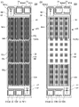
- FIG. 32 is a front view schematically showing a conventional fuel cell stack 920.
- FIG. 33 and 34 are plan views of a type CA separator 921 in a conventional fuel cell stack 920.
- FIG. 33 is a plan view seen from the fuel cell gas supply diffusion layer (cathode gas supply diffusion layer) 942 side
- FIG. 34 is a view from the fuel cell gas supply diffusion layer (anode gas supply diffusion layer) 941 side.
- is a plan view. 35 is a cross-sectional view taken along line AA of FIG. 33.
- the conventional fuel cell stack 920 includes a plurality of separators ( It has a structure in which a type CA separator 921, a type A separator 922, a type C separator 923, and a type AW separator 924) are laminated.
- a of the type CA separator 921, the type A separator 922, and the type AW separator 924 represents the gas supply diffusion layer (anode gas supply diffusion layer) 941 for the fuel cell
- the type CA separator 921 and the type C separator 'C' of the separator 923 of type AW represents the fuel cell gas supply diffusion layer (cathode gas supply diffusion layer) 942
- 'W' of the type AW separator 924 represents the cooling water supply diffusion layer.
- the fuel cell gas supply diffusion layer, separator, and fuel cell stack as described above can be used for electrolysis (generating cathode gas and anode gas) by using water instead of gas with almost the same configuration. It is considered possible. Further, the fuel cell gas supply diffusion layer, the separator, and the fuel cell cell stack as described above have almost the same structure, and a methanol fuel cell (methanol aqueous solution anode, methanol aqueous solution anode, Air cathode), lithium ion/air batteries (air cathode) and redox flow batteries (anode/cathode fed with aqueous vanadium ion solution).
- methanol fuel cell methanol aqueous solution anode, methanol aqueous solution anode, Air cathode
- lithium ion/air batteries air cathode
- redox flow batteries anode/cathode fed with aqueous vanadium ion solution.
- gas diffusion layer is used as an expression including “fuel cell gas supply diffusion layer” (expression regardless of whether it is for fuel cells or for electrolysis), and “fuel cell cell stack” is used.
- Electric reactor is used as an expression including The term “gas diffusion layer” means “a layer whose main purpose is to diffuse gas”, and it is also possible to diffuse or circulate substances other than gas (especially liquids such as water) inside the layer. .
- an object of the present invention is to provide a gas diffusion layer, a separator, and an electrochemical reaction device that can increase the reaction efficiency more than conventionally.
- the gas diffusion layer comprises a sheet-like porous body layer that is permeable and diffuseable for gas and has electrical conductivity, and one surface of the porous body layer, each of which has the gas a gas diffusion layer having a plurality of gas flow channel grooves formed from an inflow side to an outflow side of the gas, wherein the plurality of gas flow channel grooves are formed on the gas inflow side A gas inflow side groove and a plurality of gas outflow side grooves formed on the outflow side of the gas, the plurality of gas inflow side grooves being a gas diffusion layer including two or more types of gas inflow side grooves having different lengths. .
- a separator according to an embodiment of the present invention is a separator comprising a gas shielding plate and a gas diffusion layer disposed on at least one surface of the gas shielding plate, wherein the gas diffusion layer is the gas diffusion layer of the present invention.
- the diffusion layer is disposed with respect to the gas shield plate so that the plurality of gas flow channel grooves are located on the gas shield plate side, and the gas flow channel grooves and the gas shield plate are arranged to separate the gas from the gas shield plate.
- a separator having a flow path.
- An electrochemical reaction device is an electrochemical reaction device in which a separator and a membrane electrode assembly are laminated, wherein the separator is the separator of the present invention, and the separator and the membrane
- the electrode assembly is an electrochemical reactor in which the membrane electrode assembly is laminated in a positional relationship such that the membrane electrode assembly is positioned on the side of the gas diffusion layer on which the plurality of gas channel grooves are not formed.
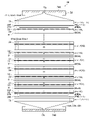
- FIG. 1 is a front view schematically showing a fuel cell stack 20 according to Embodiment 1.
- FIG. 1 is a side view schematically showing a fuel cell stack 20 according to Embodiment 1.
- FIG. 4 is a diagram shown for explaining a membrane electrode assembly (MEA) 81;
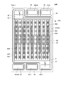
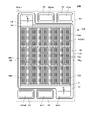
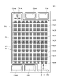
- 2 is a plan view of the fuel cell separator 23A according to Embodiment 1.
- FIG. 2 is a cross-sectional view of the fuel cell separator 23A according to Embodiment 1.
- FIG. 5 is a view for explaining gas inflow side grooves 53a and 53b and gas outflow side grooves 54a and 54b in the fuel cell gas supply diffusion layer 42A according to Embodiment 1.
- FIG. 5 is a view for explaining relay grooves 55a to 55d and communication grooves 56a and 56b in the fuel cell gas supply diffusion layer 42A according to Embodiment 1.
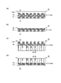
- FIG. 3 is a cross-sectional view of separators (fuel cell separators 21, 22, 24, 25) other than the fuel cell separator 23A according to Embodiment 1.
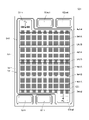
- FIG. 4 is a plan view of a fuel cell separator 23B according to Embodiment 2;
- FIG. 10 is a view for explaining gas inflow side grooves 53c to 53f and gas outflow side grooves 54c to 54f in a fuel cell gas supply diffusion layer 42B according to Embodiment 2;
- FIG. 10 is a view for explaining a relay groove 55e and a communication groove 56c in a fuel cell gas supply diffusion layer 42B according to Embodiment 2;
- FIG. 8 is a plan view of a fuel cell separator 23C according to Embodiment 3;
- FIG. 11 is a view for explaining gas inflow side grooves 53g to 53j and gas outflow side grooves 54g to 54j in a fuel cell gas supply diffusion layer 42C according to Embodiment 3;
- FIG. 11 is a view for explaining relay grooves 55d to 55j and communication grooves 56d and 56e in a fuel cell gas supply diffusion layer 42C according to Embodiment 3;
- FIG. 11 is a plan view of a fuel cell separator 23D according to Embodiment 4;
- FIG. 10 is a view for explaining gas inflow side grooves 53k to 53n and gas outflow side grooves 54k and 54l in a fuel cell gas supply diffusion layer 42D according to Embodiment 4;
- FIG. 10 is a view for explaining relay grooves 55k to 55p in a fuel cell gas supply diffusion layer 42D according to Embodiment 4;
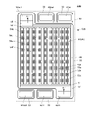
- FIG. 11 is a plan view of a fuel cell separator 23E according to Embodiment 5;
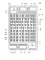
- FIG. 11 is a plan view of a fuel cell separator 23F according to Embodiment 6;
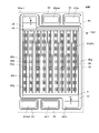
- FIG. 11 is a plan view of a fuel cell separator 23G according to Embodiment 7;
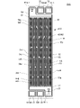
- FIG. 11 is a plan view of a fuel cell separator 23H according to Embodiment 8;
- FIG. 4 is a plan view of a fuel cell separator 23I in a comparative example
- FIG. 3 is a plan view of a fuel cell separator 22A for anode gas used in a test example
- FIG. 11 is a diagram shown for explaining division of regions when measuring a current density distribution in Test Example 3
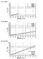
- 4 is a graph showing the results of Test Example 1 (relationship between the pattern of the gas channel grooves and the power generation characteristics).
- 4 is a graph showing the results of Test Example 2 (the relationship between the pattern of the gas channel grooves and the pressure loss in the fuel cell gas supply diffusion layer).
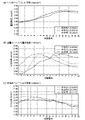
- 10 is a graph showing the results of Test Example 3 (relationship between the pattern of the gas channel grooves and the current density distribution in the fuel cell gas supply diffusion layer).
- FIG. 1 is a graph showing the results of Test Example 1 (relationship between the pattern of the gas channel grooves and the power generation characteristics).
- 4 is a graph showing the results of Test Example 2 (the relationship between the pattern of the gas channel grooves and
- FIG. 10 is a plan view of a fuel cell separator 23J according to Modification 1; 10 is a plan view of a fuel cell separator 23K according to Modification 2.
- FIG. 10 is a plan view of a fuel cell separator 23L according to Modification 3.
- FIG. 11 is a plan view of a fuel cell separator 23M according to Modification 4;
- FIG. 4 is a front view schematically showing a conventional fuel cell stack 920;
- FIG. 4 is a plan view of a type CA fuel cell separator 921 in a conventional fuel cell stack 920 .
- FIG. 4 is a plan view of a type CA fuel cell separator 921 in a conventional fuel cell stack 920 .
- FIG. 34 is a cross-sectional view taken along line AA of FIG. 33;
- FIG. 1 is a front view schematically showing a fuel cell stack 20 (electrochemical reactor) according to Embodiment 1.
- FIG. 2 is a side view schematically showing the fuel cell stack 20 according to Embodiment 1.
- FIG. 1 is a front view schematically showing a fuel cell stack 20 (electrochemical reactor) according to Embodiment 1.
- FIG. 2 is a side view schematically showing the fuel cell stack 20 according to Embodiment 1.
- FIG. 1 is a front view schematically showing a fuel cell stack 20 (electrochemical reactor) according to Embodiment 1.
- FIG. 2 is a side view schematically showing the fuel cell stack 20 according to Embodiment 1.
- the fuel cell stack 20 (electrochemical reactor) according to the first embodiment is a fuel cell stack in which fuel cell separators 21, 22, 23A, and 24 (separators) and a membrane electrode assembly 81 are stacked. be. Furthermore, the fuel cell stack 20 is a polymer electrolyte fuel cell (PEFC). The fuel cell stack 20 has a plurality of single cells. Each cell of the fuel cell stack 20 has a membrane electrode assembly 81, and an element constituting a cathode side and an element constituting an anode side with the membrane electrode assembly 81 interposed therebetween.
- PEFC polymer electrolyte fuel cell
- a cathode gas supply diffusion layer C is formed on one surface of a metal plate 30 (gas shield plate), and an anode gas supply diffusion layer A is formed on the other surface (a type CA separator).
- the fuel cell separator 22 has an anode gas supply diffusion layer A formed on one surface of a metal plate 30 (type A separator).
- the fuel cell separator 23A has a cathode gas supply diffusion layer C formed on one surface of a metal plate 30 (type C separator).
- the fuel cell separator 24 has a cathode gas supply diffusion layer C formed on one surface of a metal plate 30 and a cooling water supply diffusion layer W formed on the other surface (type CW separator).
- Each cell is arranged so that the cathode side and the anode side alternate.
- the cathode gas supply diffusion layer C and the anode gas supply diffusion layer A are provided facing each other with a membrane electrode assembly (MEA) 81 interposed therebetween.
- MEA membrane electrode assembly
- a cooling water supply diffusion layer W is provided for supplying cooling water every time two unit cells are arranged.
- the cooling water supply diffusion layer W may be provided every other single cell, or every three or more single cells.
- Fuel cell separators 21, 22, 23A, and 24 are combined and laminated such that the metal plate 30 (preferably the metal plate 30 in the type A or type C separator) faces the cooling water supply diffusion layer W.
- an anode gas supply diffusion layer A is formed on one surface of the metal plate 30, and a cooling water supply diffusion layer W is formed on the other surface. It may also have a formed (type AW separator). Further, a separator (type W separator) having a cooling water supply diffusion layer W formed on one surface of the metal plate 30 may be provided. Further, a separator having a cooling water supply diffusion layer W formed on both sides of a metal plate may be provided. The details of the configuration of each separator will be described later.
- Current collecting plates 27A and 27B are arranged at both ends of the stacked cells. Further, end plates 75 and 76 are arranged outside the current collector plates 27A and 27B via insulating sheets 28A and 28B.
- the fuel cell separators 21 , 22 , 23 A, 24 are pressed from both sides by end plates 75 , 76 . It is preferable that the metal plates 30 (corrosion-resistant layers) of the separators located at both ends of the fuel cell stack 20 and in contact with the current collector plates 27A and 27B face outward.
- the fuel cell separators 21, 22, 23A, 24, the membrane electrode assembly 81, the current collector plates 27A, 27B, the insulating sheets 28A, 28B, and the end plates 75, 76 are clearly shown. Although drawn spaced apart for purposes of illustration, they are closely attached to each other in the order of arrangement shown.
- the joining method is not particularly limited.
- the members may be joined only by pressing them from both sides by the end plates 75 and 76, or the respective members may be joined from both sides by the end plates 75 and 76 after adhering appropriate positions of the members with an adhesive. It may be joined by pressing, or may be joined by other methods.
- Each fuel cell separator 21, 22, 23A, 24, membrane electrode assembly 81, collector plates 27A, 27B, insulating sheets 28A, 28B, etc. have a thickness of, for example, about 100 ⁇ m to about 10 mm. Each figure in each embodiment of this specification exaggerates thickness and is drawn.
- An anode gas supply port 71in, a cathode gas discharge port 72out, and a cooling water discharge port 73out are provided at one end of the end plate 75 on the anode side.
- an anode gas outlet 71out, a cathode gas supply port 72in, and a cooling water supply port 73in are provided at one end of the end plate 75 on the anode side.
- Corresponding fluid supply pipes and fluid discharge pipes are connected to these supply ports and discharge ports, respectively.
- Each fuel cell separator 21, 22, 23A, 24 has an anode gas inlet 61in communicating with the anode gas supply port 71in, a cathode gas (and generated water) outlet 62out communicating with the cathode gas outlet 72out, A cooling water outlet 63out communicating with the cooling water outlet 73out is provided.
- Each of the fuel cell separators 21, 22, 23A, and 24 has an anode gas outlet 61out communicating with the anode gas outlet 71out, a cathode gas inlet 62in communicating with the cathode gas supply port 72in, and a cooling device.
- a cooling water inlet 63in communicating with the water supply port 73in is provided.
- a cathode gas, an anode gas, and cooling water are supplied through an anode gas supply port 71in, a cathode gas supply port 72in, and a cooling water supply port 73in.
- hydrogen gas is used as the anode gas and air is used as the cathode gas.
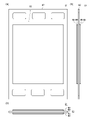
- FIG. 3 is a diagram for explaining a membrane electrode assembly (MEA) 81.
- FIG. 3(a) is a plan view of the membrane electrode assembly 81
- FIG. 3(b) is a front view of the membrane electrode assembly 81
- FIG. 3(c) is a side view of the membrane electrode assembly.
- the membrane electrode assembly 81 includes an electrolyte membrane (PEM) 82, catalyst layers (CL) 85 arranged on both sides of the electrolyte membrane 82, and outside surfaces of each catalyst layer 85. and a microporous layer (MPL) 83 .
- PEM electrolyte membrane
- CL catalyst layers
- MPL microporous layer
- the one composed of the electrolyte membrane 82 and the catalyst layers 85 arranged on both sides thereof is referred to as a catalyst coated membrane (CCM).
- the microporous layer 83 has finer pores (pores) than the porous layer 40 . Note that the microporous layer 83 can be omitted. Further, as will be described later in modification 7, when direct application of the microporous layer 83 to the catalyst layer 85 is omitted, the microporous layer 83 is in contact with the catalyst layer 85 of the fuel cell gas supply diffusion layer 41. , 42A.
- FIG. 4 is a plan view of the fuel cell separator 23A.
- FIG. 4 is a plan view of the type C fuel cell separator 23A viewed from the metal plate 30 side. Illustration of 30 is omitted. In the plan views of the separator, including FIG. Even if there are a plurality of shaped grooves, in principle only one arbitrary groove is labeled.
- FIG. 5 is a cross-sectional view of the fuel cell separator 23A according to Embodiment 1.
- FIG. 5(a) is a cross-sectional view along line A1-A1 of FIG. 4
- FIG. 5(b) is a cross-sectional view along line A2-A2 of FIG. 4
- FIG. 5(c) is a cross-sectional view of FIG. 2 is a cross-sectional view taken along line A3-A3 of FIG.
- FIG. 5 shows the fuel cell separator 23A with the membrane electrode assembly 81 joined. Also, illustration of the cross-sectional structure of the membrane electrode assembly 81 is omitted.
- FIG. 5 shows the fuel cell separator 23A with the membrane electrode assembly 81 joined. Also, illustration of the cross-sectional structure of the membrane electrode assembly 81 is omitted.
- FIG. 6 is a view for explaining gas inflow side grooves 53a and 53b and gas outflow side grooves 54a and 54b in the fuel cell separator 23A according to the first embodiment.
- FIG. 7 is a view for explaining the relay grooves 55a to 55d and the communication grooves 56a and 56b in the fuel cell separator 23A according to the first embodiment.
- illustration of the relay grooves 55a to 55d and the communication grooves 56a and 56b is omitted in FIG. 6, and in FIG. Illustration is omitted.
- the fuel cell separator 23A comprises a metal plate 30 as a gas shielding plate and a fuel cell gas supply diffusion layer 42A provided on at least one surface of the metal plate 30. separator.
- the metal plate 30 is hatched to indicate a cross section.
- the metal plate 30 is preferably a metal made of one or more of Inconel, nickel, gold, silver and platinum, or a metal plating or clad material on an austenitic stainless steel plate. Corrosion resistance can be improved by using these metals.
- a cathode gas inlet 62in, a cooling water inlet 63in, and an anode are provided in the order of right, center, and left in FIG.
- a gas outlet 61out is provided.
- a cathode gas outlet 62out, a cooling water outlet 63out, and an anode gas inlet 61in are provided in this order from left to right in FIG.
- the inflow ports 61in, 62in, 63in, the outflow ports 61out, 62out, 63out, and the formation regions of the fuel cell gas supply diffusion layer 42A are surrounded by electronically conductive or non-electronically conductive dense frames 32. being surrounded.
- the dense frame 32 prevents leakage of anode gas, cathode gas and cooling water.
- the outer surface of the dense frame 32 surrounds the inflow ports 61in, 62in, and 63in, the outflow ports 61out, 62out, and 63out, and the region where the fuel cell gas supply diffusion layer 42A is formed.
- a groove is formed (not shown).
- a gasket (sealing material such as packing or O-ring) 33 is arranged in this groove.
- a corrosion-resistant layer (not shown in FIG. 5) are formed on both sides of the metal plate 30, except for the portions where the inlets 61in, 62in, 63in and the outlets 61out, 62out, 63out are provided. Corrosion-resistant layers may be formed on the inner peripheral surfaces of the inlets 61in, 62in, 63in and the outlets 61out, 62out, 63out. Corrosion-resistant layers may be formed on the side surfaces and end surfaces of the metal plate 30 .
- the corrosion-resistant layer is preferably a dense layer having the same composition as the dense frame 32 and has the effect of suppressing corrosion of the metal plate 30 .
- the fuel cell separator 23A is a type C separator, and as shown in FIGS.
- a gas supply diffusion layer 42A is formed. That is, the fuel cell gas supply diffusion layer 42A is a fuel cell gas supply diffusion layer for the cathode gas.
- the fuel cell gas supply diffusion layer 42A is composed of a sheet-like porous body layer 40 that allows permeation and diffusion of gas and also has electrical conductivity, and one surface of the porous body layer 40 is filled with gas (fuel).
- the battery separator 23A has a plurality of gas channel grooves formed from the inflow side to the outflow side of the cathode gas. The plurality of gas channel grooves are arranged with respect to the metal plate 30 (gas shield plate) so as to be positioned on the metal plate 30 (gas shield plate) side.
- the fuel cell separator 23A and the membrane electrode assembly 81 are located at the position where the membrane electrode assembly 81 is located on the side of the fuel cell gas supply diffusion layer 42A on which the plurality of gas channel grooves are not formed. are stacked in relation to each other (see FIG. 5). Note that the "gas channel groove” and “gas channel” are not exclusive for gas, and can be used to circulate substances other than gas (in particular, liquids such as water).
- the gas The flow path does not need to be formed along the above-described diagonal line, and the direction "from the gas inflow side to the outflow side" as in Embodiment 1 is defined as "the porous body layer 40 as a whole.”
- the direction of gas flow in the mass layer 40 is vertical from the bottom to the top of the page of FIG. 4, as shown in FIG.
- a plurality of gas flow channel grooves may be formed along this direction, or may be formed along other directions.
- the plurality of gas channel grooves are formed on the gas inflow side (lower part in FIGS. 4 and 6) and the gas outflow side (upper part in FIGS. 4 and 6). and a plurality of gas outlet grooves 54a, 54b formed therein.
- the plurality of gas inflow side grooves 53a, 53b include two or more types (in this case, two types) of gas inflow side grooves 53a, 53b having different lengths.
- two adjacent gas inflow side grooves 53a and 53b have different lengths (see FIG. 6).
- the position of the end of the outflow side of two gas inflow side grooves 53a and 53b adjacent along the "x direction" perpendicular to the "y direction" from the gas inflow side to the outflow side is along the "y direction”. are spaced apart from each other.
- at least one of the three adjacent gas inflow grooves has a length different from that of the other gas inflow grooves.
- At least one of the gas inlet gutters will have a different length than the other gas inlet gutters.
- At least one gas inflow side groove out of three adjacent gas inflow side grooves has a length different from that of the other gas inflow side grooves
- at least one out of four adjacent gas inflow side grooves One gas inflow side groove has a length different from other gas inflow side grooves
- three adjacent gas inflow side grooves are defined as one group of gas inflow side grooves, a plurality of groups included in the gas diffusion layer of the gas inflow side groove groups, at least one of the three gas inflow side grooves has a length different from that of the other gas inflow side grooves”
- four adjacent gas inflow side grooves When a side ditch is defined as one set of gas inflow side groove groups, at least one of the four gas inflow side grooves is at least one has a different length than the other gas inlet gutters.” The same applies to the gas outflow side groove, which will be described later.
- the plurality of gas outflow grooves 54a, 54b include two or more types (in this case, two types) of gas outflow grooves 54a, 54b having different lengths.
- Two adjacent gas outlet grooves 54a and 54b have different lengths (see FIG. 6).
- the two gas outflow side grooves 54A and 54B adjacent to each other along the "x direction" have starting ends on the inflow side separated from each other along the "y direction.”
- at least one of the three adjacent gas outflow grooves has a length different from that of the other gas outflow grooves.
- At least one of the gas outlet gutters will also have a different length than the other gas outlet gutters.
- the gas inflow side groove 53a which has the shortest length among the plurality of gas inflow side grooves 53a and 53b, extends along the gas outflow side of the porous body layer 40 from the gas inflow side.
- the gas inflow side groove 53b which has a length less than 30% of the length of the gas inflow side grooves 53a and 53b and has the longest length among the plurality of gas inflow side grooves 53a and 53b, extends from the gas inflow side to the gas outflow side of the porous body layer 40. It has a length of 40% or more of the length.
- the gas inflow side groove 53a which has the shortest length among the plurality of gas inflow side grooves 53a and 53b, extends along the gas outflow side of the porous body layer 40 from the gas inflow side. It has a length less than 30% of the height.
- the gas outflow side groove 54b which has the longest length among the plurality of gas outflow side grooves 54a and 54b, has a length of 30% or more of the length along the gas outflow side from the gas inflow side of the porous body layer 40. have.
- the plurality of gas flow path grooves are formed between the gas inflow side grooves 53a, 53b and the gas outflow side grooves 54a, 54b. and a plurality of relay grooves 55a to 55d.
- the plurality of relay grooves 55a to 55d communicate along a direction (x direction) perpendicular to the direction from the gas inflow side to the outflow side.
- the relay grooves 55a and 55b communicate with each other through a communication groove 56a
- the relay grooves 55c and 55d communicate with each other through a communication groove 56b (see FIG. 7).
- the plurality of relay grooves 55a to 55d are formed in two stages in the fuel cell gas supply diffusion layer 42A.
- an appropriate chamfering process or a rounding process may be performed on the corners or corners of the gas flow channel grooves, such as the communicating parts between the relay grooves and the communication grooves.
- the plurality of gas inflow side grooves 53a, 53b, the plurality of gas outflow side grooves 54a, 54b, and the plurality of relay grooves 55a to 55d are formed so as to enter each other (see FIGS. 4 and 5). Further, when the fuel cell gas supply diffusion layer 42A is viewed from above, the ratio of the area of the gas channel groove formation region to the area of the entire porous body layer 40 is in the range of 30% to 80%. The area ratio is preferably in the range of 40% to 70%.
- the porous body layer 40 contains a mixture of a conductive material (preferably a carbon-based conductive material) and a polymer resin.
- a conductive material preferably a carbon-based conductive material
- the fluid resistance of the porous layer 40 depends on the porosity of the porous layer and the area of the surface through which the fluid flows. The higher the porosity, the lower the fluid resistance. The larger the area through which the fluid flows, the smaller the fluid resistance.
- the porosity of the porous body layer 40 is about 50 to 85%.
- the porous layer 40 has a porosity of about 30 to 85%.
- the porosity of the porous body layer 40 is configured as described above, the cathode between the gas flow channel grooves and the porous body layer 40 through the inner surfaces of the plurality of gas flow channel grooves.
- a large amount of gas can be uniformly supplied to the membrane electrode assembly, and cathode gas that was not used during power generation and The generated steam and condensed water can be efficiently discharged out of the gas channel groove.
- the porosity of the fuel cell gas supply diffusion layer 42A can be adjusted, and thus the movement resistance of the fuel cell gas supply diffusion layer 42A can be adjusted.
- the transfer resistance is decreased (porosity is increased).
- the migration resistance increases (the porosity decreases).
- the corrosion-resistant layer and the dense frame 32 are also a mixture of a carbon-based conductive material and a polymer resin, and are preferably densified while ensuring conductivity by an appropriate content of the carbon-based conductive material.
- the carbon-based conductive material is not particularly limited, but for example, graphite, carbon black, diamond-coated carbon black, silicon carbide, titanium carbide, carbon fiber, carbon nanotube, etc. can be used. Both thermosetting resins and thermoplastic resins can be used as the polymer resin. Examples of polymer resins include phenolic resins, epoxy resins, melamine resins, rubber resins, furan resins, vinylidene fluoride resins, and the like.
- An inflow passage 57 is formed between the cathode gas inlet 62in and the region where the porous layer 40 is formed (see FIG. 4).
- An outflow passage 58 is formed between the cathode gas outflow port 62out and the region where the porous layer 40 is formed.
- These inflow passage 57 and outflow passage 58 are for supporting the membrane electrode assembly 81 or its frame 81A. Therefore, any structure may be used as long as the cathode gas can flow smoothly and the membrane electrode assembly 81 can be supported. For example, it may be a porous layer with a very large porosity, or a structure in which a large number of struts are arranged.
- An elongated gas inflow side step 51 is formed along the width direction of the metal plate 30 in a region of the porous layer 40 facing the inflow passage 57 .
- a narrow gas outflow side step 52 is also formed along the width direction of the metal plate 30 in a region of the porous body layer 40 facing the outflow passage 58 .
- the gas inflow side step 51 and the gas outflow side step 52 may be omitted.
- the porous layer 40, the inflow passage 57, and the outflow passage 58 are formed at the same height (thickness) as the dense frame 32.
- the surface of the fuel cell gas supply diffusion layer 42A facing the metal plate 30 is provided with a plurality of gas flow channel grooves formed of voids.
- a plurality of gas flow paths are formed in the gap between the A plurality of gas inflow side grooves 53 a and 53 b communicate with an inflow passage 57 via a gas inflow side step 51 , and a plurality of gas outflow side grooves 54 a and 54 b communicate with an outflow passage 58 via a gas outflow side step 52 .
- the number and structure of the gas channel grooves are not limited to those illustrated.
- the width of the porous body layer 40 is, for example, It is about 30 mm to 300 mm.
- the width of the gas channel groove is, for example, about 0.3 mm to 2 mm.
- the thickness of the porous layer 40 is, for example, about 150 to 400 ⁇ m, and the depth of the gas channel groove is, for example, about 100 to 300 ⁇ m.
- the distance from the surface (ceiling thickness) is, for example, about 100 to 300 ⁇ m.
- the size is not limited to the above size. , a suitable size can be used according to the required performance and the like.
- the fuel cell gas supply diffusion layer 41 in the type A fuel cell separator 22 also basically has the same configuration as the fuel cell gas supply diffusion layer 42A. However, since the gas supplied to the gas supply diffusion layer is hydrogen gas, it has a lower porosity and a thinner thickness than the fuel cell gas supply diffusion layer 42A (see FIG. 8B described later). .
- a fuel cell gas supply diffusion layer 41 and a fuel cell gas supply diffusion layer 42A are used as gas diffusion layers (see FIG. 8A described later).
- a cooling water supply diffusion layer is formed on the surface of the type C fuel cell separator 23A on which the fuel cell gas supply diffusion layer 42A is not formed (Fig. 8(c)).
- the type AW fuel cell separator 25 has a cooling water supply diffusion layer formed on the surface of the type A fuel cell separator 22 on which the fuel cell gas supply diffusion layer 41 is not formed (Fig. 8(d)).
- protons H +
- anode gas hydrogen gas
- the protons diffuse through the membrane electrode assembly 81, move to the oxygen electrode side, and react with oxygen to produce water.
- the generated water is discharged from the oxygen electrode side.
- the air flowing in from the cathode gas inlet 62in passes through the inflow passage 57 and the gas inflow side step 51. , into the gas inflow side grooves 53a and 53b.
- Part of the air that has flowed into the gas inlet side step 51 enters the gas channel groove and enters the porous body layer 40 (gas diffusion layer 43) from the gas channel groove, and the other part enters the porous body layer 40 (gas diffusion layer 43). It enters the porous body layer 40 (gas diffusion layer 43) directly from the end face of the porous body layer 40 (gas diffusion layer 43) and diffuses in the porous body layer 40 (gas diffusion layer 43).
- the air diffuses in the thickness direction while diffusing in the planar direction within the porous body layer 40 (gas diffusion layer 43), and the membrane electrode junction provided in contact with the porous body layer 40 (gas diffusion layer 43) is formed. It is supplied to the body 81 and contributes to the power generation reaction. Gases not used for power generation (unused oxygen gas and nitrogen gas) and water (water vapor or condensed water) generated during power generation pass through the porous body layer 40 (gas diffusion layer 43), the gas channel grooves, and the gas outflow. It flows out to the outflow passage 58 via the side step 52 .
- the fuel cell gas supply diffusion layer 42A according to Embodiment 1 has the above characteristics, the water (water vapor or condensed water) generated in the membrane electrode assembly 81 during power generation is transferred to the porous body layer 40 and It becomes possible to efficiently discharge to the outside of the gas flow channel groove through the gas flow channel groove.
- one surface of the porous body layer 40 has a plurality of gas flow channel grooves (gas inflow side grooves 53a and 53b, gas outflow side grooves 54a and 54b, and relay grooves 54a and 54b). Since the grooves 55a to 55d) are formed, the gas movement resistance is reduced compared to the conventional method, and a larger amount of gas can be supplied to the membrane electrode assembly than the conventional method.
- the porous layer 40 since a plurality of gas channel grooves are formed on one surface of the porous layer 40, the porous layer 40 Since gas is always supplied to the membrane electrode assembly 81 arranged on the other surface through the porous layer 40, a plurality of gas flow paths extend from one surface of the porous layer 40 to the other surface. The gas can be more uniformly supplied to the membrane electrode assembly 81 than in the case where the openings are formed through the openings.
- the gas since a plurality of gas channel grooves are formed on one surface of the porous body layer 40, the gas is not used for power generation. Since the gas (in this case, the cathode gas (oxygen gas, nitrogen gas) for the fuel cell) can be efficiently discharged out of the gas channel groove through the porous layer 40 and the gas channel groove, Further, in the underflow region formed between the plurality of gas inflow side grooves 53a, 53b and the plurality of gas outflow side grooves 54a, 54b, the gas not used for power generation is pushed out by the underflow gas flow, and is discharged into the gas flow path grooves.
- the gas in this case, the cathode gas (oxygen gas, nitrogen gas) for the fuel cell
- the membrane electrode assembly can Since a plurality of gas flow channel grooves are formed on one surface of the porous body layer 40, the membrane electrode assembly can Since the moisture (water vapor or condensed water) generated in 81 can be efficiently discharged out of the gas channel grooves through the porous body layer 40 and the gas channel grooves, Since moisture (water vapor or condensed water) can be efficiently discharged out of the gas flow channel grooves in the form of being pushed out by the gas flow, the gas diffusion layer has better drainage than conventional ones.
- the plurality of gas channel grooves include the plurality of gas inflow side grooves 53a, 53b and the plurality of gas outflow side grooves 54a, 54b.
- the plurality of gas inflow side grooves 53a and 53b since the gas inflow side grooves 53a and 53b include two or more types of gas inflow side grooves 53a and 53b having different lengths, gas inflow side grooves having a relatively short length among the plurality of gas inflow side grooves
- the action of 53a (end portion on the outflow side) makes it difficult for the porous layer 40 in the inflow side region, which is originally easy to dry, to be less likely to dry, thereby suppressing a decrease in reaction efficiency due to excessive drying of the porous layer 40 .
- the fuel cell gas supply diffusion layer 42A according to the first embodiment can have a higher reaction efficiency (in the case of the first embodiment, the power generation efficiency of the fuel cell) than the conventional one, and furthermore, has a higher drainage property than the conventional one. It becomes an excellent gas diffusion layer.
- the two adjacent gas inflow grooves 53a and 53b have different lengths, that is, the two gas inflow grooves 53a and 53b adjacent in the x direction have different lengths. Since the positions of the outflow-side end portions (dead-end portions) of 53b exist at positions spaced apart along the y direction, the outflow-side end portions are further dispersed. As a result, the gas supply diffusion layer 42A for a fuel cell according to Embodiment 1 can further increase the reaction efficiency, and furthermore, become a gas diffusion layer with even better drainage.
- At least one gas inflow side groove among four or three adjacent gas inflow side grooves may have a length different from that of the other gas inflow side grooves. Even in this case, the fuel cell gas supply diffusion layer has the same effect as when two adjacent gas inlet grooves have different lengths.
- the gas inflow side groove 53a having the shortest length among the plurality of gas inflow side grooves 53a and 53b is located on the gas inflow side of the porous body layer 40. Since the length is less than 30% of the length along the outflow side, the decrease in reaction efficiency due to excessive drying of the porous body layer 40 can be further suppressed. Further, according to the fuel cell gas supply diffusion layer 42A according to the first embodiment, the gas inflow side groove 53b having the longest length among the plurality of gas inflow side grooves 53a and 53b is the gas inflow side of the porous body layer 40. Since it has a length of 40% or more of the length along the outflow side, it is possible to further improve the drainage performance and further suppress the decrease in reaction efficiency due to the decrease in gas pressure.
- the plurality of gas outflow side grooves 54a, 54b include two or more types of gas outflow side grooves 54a, 54b having different lengths. Therefore, according to the fuel cell gas supply diffusion layer 42A according to the first embodiment, the plurality of gas outflow side grooves 54a and 54b include two or more types of gas outflow side grooves 54a and 54b having different lengths.
- the discharge efficiency of moisture (water vapor and condensed water) that is likely to stay is increased, gas diffusion is promoted, and the reaction efficiency (implementation In the case of form 1, power generation efficiency) can be enhanced.
- a predetermined reaction is caused by the underflow of gas from the upstream gas diffusion grooves. In the case of , power generation is performed, and the reaction efficiency as a whole (power generation efficiency in the case of Embodiment 1) can be increased.
- the two adjacent gas outflow side grooves 54a and 54b have different lengths, so long grooves and short grooves are arranged in a dispersed manner.
- the gas supply diffusion layer 42A for a fuel cell according to Embodiment 1 can have a higher reaction efficiency and a gas diffusion layer with even better drainage.
- At least one gas outflow side groove among four or three adjacent gas outflow side grooves may have a length different from that of the other gas outflow side grooves. Even in this case, the fuel cell gas supply diffusion layer has the same effect as when two adjacent gas outlet grooves have different lengths.
- the gas inflow side groove 53a which has the shortest length among the plurality of gas inflow side grooves 53a and 53b, is the gas inflow side of the porous body layer 40. Since it has a length of less than 30% of the length along the outflow side from the side, it is possible to make it particularly difficult to dry the porous body layer 40 on the inflow side, which is easy to dry, and it is possible to further increase the reaction efficiency. It becomes possible.
- the gas outflow side groove 54b which has the longest length among the plurality of gas outflow side grooves 54a and 54b, is the one that allows the gas to flow into the porous body layer 40. Since it has a length of 30% or more of the length along the outflow side from the side, the moisture (water vapor, condensed water) that tends to stay is efficiently discharged through the gas outflow side groove 54b, promoting gas diffusion. From this point of view as well, the reaction efficiency can be further increased.
- the outflow end portion (dead end portion) is It becomes possible to increase the number, and it becomes possible to further increase the reaction efficiency by increasing the amount of gas passing through the subsoil region. It is also possible to optimize the balance between preventing drying of the porous layer 40 and improving the efficiency of discharging moisture (water vapor and condensed water).
- the plurality of relay grooves 55a to 55d are arranged along the direction (x direction) perpendicular to the direction from the gas inflow side to the gas outflow side. Therefore, it is possible to equalize the gas pressure along the direction of communication.
- the plurality of gas inflow side grooves 53a and 53b, the plurality of gas outflow side grooves 54a and 54b, and the plurality of relay grooves 55a to 55d are arranged so as to enter each other. It is possible to equalize the gas pressure and increase the undercurrent.
- the area of the gas flow path groove formation area with respect to the area of the entire porous body layer 40 is Since the area ratio is in the range of 30% to 80%, it is possible to achieve both sufficient gas supply capability and sufficient mechanical strength.
- the fuel cell gas supply diffusion layer 42A is a fuel cell gas supply diffusion layer for the cathode gas, the performance of the fuel cell cell stack is improved. can be raised.
- a fuel cell separator 23A according to Embodiment 1 is a separator comprising a metal plate 30 as a gas shielding plate and a fuel cell gas supply diffusion layer 42A provided on at least one surface of the metal plate 30.
- the fuel cell gas supply diffusion layer 42A is the fuel cell gas supply diffusion layer 42A according to the first embodiment, and includes a plurality of gas flow path grooves (gas inflow side grooves 53a, 53b, gas outflow side grooves 54a, 54b, and relays).
- the grooves 55a to 55d) are arranged with respect to the metal plate 30 so as to be positioned on the side of the metal plate 30, and the gas flow channel is constituted by the gas flow channel grooves and the metal plate 30. It becomes a separator that can increase the reaction efficiency.
- the fuel cell stack 20 according to Embodiment 1 is a fuel cell stack in which a separator and a membrane electrode assembly 81 are stacked, and the separator is the fuel cell separator 23A according to Embodiment 1,
- the fuel cell separator 23A and the membrane electrode assembly 81 are connected to a plurality of gas channel grooves (gas inflow side grooves 53a, 53b, gas outflow side grooves 54a, 54b, and relay grooves 55a to 55b) of the fuel cell gas supply diffusion layer 42A. 55d) is not formed, the membrane electrode assembly 81 is stacked, so that the fuel cell stack can achieve a higher reaction efficiency than conventional fuel cell stacks.
- the fuel cell stack 20 since the fuel cell stack 20 is a fuel cell stack, it becomes a fuel cell stack that can increase the power generation efficiency of the fuel cell as compared with the conventional fuel cell stack.
- the corrosion-resistant layer, dense frame 32, fuel cell gas supply diffusion layer 42A, etc. are made of thermosetting resin (or thermoplastic resin), carbon-based conductive material powder (and carbon fiber depending on the situation), resin powder. It can be formed by isostatic pressing using a paste-like material obtained by kneading and kneading a volatile solvent.
- the unique shape of each member and portion can be formed, for example, by printing, stamping, squeezing, or the like.
- each member can be arranged or formed by thermocompression bonding or roll press (hot press).
- the manufacturing method described above can also be applied when manufacturing separators (fuel cell separators 21, 22, 24, 25) other than the fuel cell separator 23A.
- FIG. 8 is a sectional view of a separator (fuel cell separators 21, 22, 24, 25) other than the fuel cell separator 23A.
- 8(a) is a sectional view of a type CA fuel cell separator 21
- FIG. 8(b) is a sectional view of a type A fuel cell separator 22
- FIG. 8(c) is a type CW fuel cell separator.
- FIG. 8D is a cross-sectional view of a fuel cell separator 25 of type AW.
- FIG. 8 is a cross-sectional view corresponding to the A1-A1 cross section (see FIG. 5A) of the fuel cell separator 23A.
- FIG. 8 since it would be difficult to understand the drawing if all of the plurality of gas flow channel grooves are numbered, only one gas flow channel groove is a gas flow channel groove (gas inflow side groove, gas outflow side groove). or relay groove).
- the gas diffusion layer of the present invention can be applied to the fuel cell gas supply diffusion layer 42A (for cathode gas) and/or the fuel cell gas supply diffusion layer 41 (for anode gas) of the fuel cell separator 21 ( See FIG. 8(a).).
- the gas diffusion layer of the present invention can also be applied to the fuel cell gas supply diffusion layer 41 (for anode gas) of the fuel cell separator 22 (see FIG. 8B).
- the gas diffusion layer of the present invention can also be applied to the fuel cell gas supply diffusion layer 42A (for cathode gas) of the fuel cell separator 24 (see FIG. 8(c)).
- the gas diffusion layer of the present invention can be applied to the fuel cell gas supply diffusion layer 41 (for anode gas) of the fuel cell separator 25 (see FIG. 8(d)).
- the reaction efficiency fuel cell If it is, it becomes a gas diffusion layer that can increase the power generation efficiency.
- FIG. 9 is a plan view of a fuel cell separator 23B according to Embodiment 2.
- FIG. 10 is a view for explaining gas inflow side grooves 53c to 53f and gas outflow side grooves 54c to 54f in a fuel cell gas supply diffusion layer 42B according to the second embodiment.
- FIG. 11 is a view for explaining the relay groove 55e and the communication groove 56c in the fuel cell gas supply diffusion layer 42B according to the second embodiment.
- the fuel cell gas supply/diffusion layer 42B in the fuel cell separator 23B according to the second embodiment basically has the same configuration as the fuel cell gas supply/diffusion layer 42A according to the first embodiment.
- the configuration of the groove is different from that of the fuel cell gas supply diffusion layer 42A according to the first embodiment.
- Outflow side grooves 54c to 54f are formed in the fuel cell gas supply diffusion layer 42B according to Embodiment 2, as shown in FIGS.
- a relay groove 55e is formed so as to enter the gas inflow side grooves 53c to 53f and the gas outflow side grooves 54c to 54f.
- a plurality of relay grooves 55e are formed, and the respective relay grooves 55e communicate with each other through a communication groove 56c.
- the fuel cell gas supply diffusion layer 42B and the fuel cell separator 23B according to the second embodiment have higher reaction efficiency than the conventional one, similarly to the fuel cell gas supply diffusion layer 42A and the fuel cell separator 23A according to the first embodiment. It becomes a gas diffusion layer and a separator that can be made taller. Further, according to the fuel cell gas supply diffusion layer 42B and the fuel cell separator 23B according to the second embodiment, the same characteristics as those of the fuel cell gas supply diffusion layer 42A and the fuel cell separator 23A according to the first embodiment are used. You can also obtain the common effect of
- FIG. 12 is a plan view of a fuel cell separator 23C according to Embodiment 3.
- FIG. 13 is a view for explaining gas inflow side grooves 53g to 53j and gas outflow side grooves 54g to 54j in a fuel cell gas supply diffusion layer 42C according to the third embodiment.
- FIG. 14 is a view for explaining the relay grooves 55d to 55j and the communication grooves 56d and 56e in the fuel cell gas supply diffusion layer 42C according to the third embodiment.
- the fuel cell gas supply diffusion layer 42C in the fuel cell separator 23C according to Embodiment 3 basically has the same configuration as the fuel cell gas supply diffusion layer 42A according to Embodiment 1, except for the gas channel.
- the configuration of the groove is different from that of the fuel cell gas supply diffusion layer 42A according to the first embodiment.
- Outflow side grooves 54g to 54j are formed.
- relay grooves 55f to 55j are formed so as to enter the gas inlet side grooves 53g to 53j and the gas outlet side grooves 54g to 54j.
- the gas-inflow side grooves 53i, 53j and the relay grooves 55i, j have branching points from one groove to two grooves.
- the relay groove 55f and the relay groove 55g communicate with each other through a communication groove 56d, and the relay grooves 55f, 55g and the relay groove 55h communicate with each other through a communication groove 56d. That is, in the fuel cell gas supply diffusion layer 42C, a pair of relay grooves formed as a plurality of relay grooves so that two adjacent relay grooves communicate with each other extends from the gas inflow side to the gas outflow side. It includes a plurality of relay grooves 55f to 55h formed along a direction perpendicular to the direction.
- the fuel cell gas supply diffusion layer 42C and the fuel cell separator 23C according to the third embodiment have higher reaction efficiency than the conventional one, similarly to the fuel cell gas supply diffusion layer 42A and the fuel cell separator 23A according to the first embodiment. It becomes a gas diffusion layer and a separator that can be made taller. Further, according to the fuel cell gas supply diffusion layer 42C according to Embodiment 3, as the plurality of relay grooves, pairs of relay grooves formed so that two adjacent relay grooves communicate with each other are used for gas supply.
- the fuel cell gas supply diffusion layer 42C since a part of the plurality of gas flow channel grooves has a "branching point from one groove to two grooves", It becomes possible to equalize the gas pressure in a limited place.
- FIG. 15 is a plan view of a fuel cell separator 23D according to Embodiment 4.
- FIG. FIG. 16 is a view for explaining gas inflow side grooves 53k to 53n and gas outflow side grooves 54k and 54l in a fuel cell gas supply diffusion layer 42D according to the fourth embodiment.
- FIG. 17 is a view for explaining the relay grooves 55k to 55p in the fuel cell gas supply diffusion layer 42D according to the fourth embodiment.
- the fuel cell gas supply diffusion layer 42D in the fuel cell separator 23D according to the fourth embodiment basically has the same configuration as the fuel cell gas supply diffusion layer 42A according to the first embodiment, but the gas flow path is The configuration of the groove is different from that of the fuel cell gas supply diffusion layer 42A according to the first embodiment.
- the fuel cell gas supply diffusion layer 42D according to Embodiment 4 as shown in FIGS. Outflow side grooves 54k and 54l are formed. Further, relay grooves 55k to 55p are formed so as to enter the gas inlet side grooves 53k to 53n and the gas outlet side grooves 54k and 54l. Among these, the relay grooves 55k to 55n have a joint point from two grooves to one groove.
- the gas inflow side grooves 53k to 53n and the gas outflow side grooves 54k and 54l may be interchanged, and the relay grooves 55k to 55n may be arranged and shaped to correspond to the interchange.
- the fuel cell gas supply diffusion layer 42D and the fuel cell separator 23D according to the fourth embodiment have higher reaction efficiency than the conventional one, similarly to the fuel cell gas supply diffusion layer 42A and the fuel cell separator 23A according to the first embodiment. It becomes a gas diffusion layer and a separator that can be made taller. Further, according to the fuel cell gas supply diffusion layer 42D according to the fourth embodiment, since a part of the plurality of gas flow channel grooves has a "joint point from two grooves to one groove", It becomes possible to equalize the gas pressure in a limited place.
- the same features as those of the fuel cell gas supply diffusion layer 42A and the fuel cell separator 23A according to the first embodiment are used. You can also obtain the common effect of
- FIG. 18 is a plan view of a fuel cell separator 23E according to Embodiment 5.
- FIG. 19 is a plan view of a fuel cell separator 23F according to Embodiment 6.
- FIG. 20 is a plan view of a fuel cell separator 23G according to Embodiment 7.
- FIG. 21 is a plan view of a fuel cell separator 23H according to Embodiment 8.
- the fuel cell separators 23E to 23H and the fuel cell gas supply diffusion layers 42E to 42H according to Embodiments 5 to 8 are basically the fuel cell separators 23A to 23D and the fuel cell gas
- the fuel cell separators 23A to 23D and the fuel cell gas supply diffusion layers 42A to 42D have the same configuration as the fuel cell gas supply diffusion layers 42A to 42D, but the aspect ratios of the fuel cell gas supply diffusion layers are according to the first to fourth embodiments. different from the case of Further, in the fuel cell gas supply diffusion layers 42E to 42H according to Embodiments 5 to 8, the widths of the grooves constituting the gas channel grooves are the same as those of the fuel cell separators 23A to 23D according to Embodiments 1 to 4.
- the fuel cell gas supply diffusion layer 42E according to the fifth embodiment is the same as the fuel cell gas supply diffusion layer 42A according to the first embodiment and the fuel cell gas supply diffusion layer 42A according to the sixth embodiment.
- the supply diffusion layer 42F is the fuel cell gas supply diffusion layer 42B according to the second embodiment
- the fuel cell gas supply diffusion layer 42G according to the seventh embodiment is the fuel cell gas supply diffusion layer 42C according to the third embodiment.
- the fuel cell gas supply diffusion layer 42H according to Embodiment 8 is the same as the fuel cell gas supply diffusion layer 42D according to Embodiment 4 (see FIGS. 18 to 21).
- the fuel cell gas supply diffusion layers 42E to 42H and the fuel cell separators 23E to 23H according to Embodiments 5 to 8 are similar to the fuel cell gas supply diffusion layer 42A and the fuel cell separator 23A according to Embodiment 1.
- a gas supply diffusion layer for a fuel cell and a separator for a fuel cell are provided, which can increase the reaction efficiency more than before.
- the corresponding fuel cell gas supply diffusion layers 42A to 42D and the fuel cell separators 23A to An effect similar to that of 23D can be obtained.
- the single cells include the single cell according to Example 1 (hereinafter simply referred to as "Example 1”), the single cell according to Example 2 (hereinafter simply referred to as “Example 2”), and the single cell according to the comparative example. (hereinafter simply referred to as “comparative examples”) were manufactured and tested.
- a fuel cell separator type C separator
- a fuel cell separator type A separator
- anode gas sandwiche sandwiched a membrane electrode assembly (not shown).
- the shape of the gas channel grooves was as shown in Embodiment 5 (see FIG.
- FIG. 22 is a plan view of a fuel cell separator 23I in a comparative example.
- FIG. 22(a) is a diagram showing all the gas flow path grooves
- FIG. 22(b) is a diagram showing only the gas inflow side groove 53o and the gas outflow side groove 54m (relay grooves) among the gas flow path grooves. 55q to 55t and communication grooves 56f and 56g are not shown).
- the shape of the gas flow channel groove was the same as that formed in the fuel cell gas supply diffusion layer 42I of the fuel cell separator 23I (see FIG. 22). did.
- grooves having the same length are used as the gas inlet groove 53o and the gas outlet groove 54m.
- the relay grooves 55q to 55t communicate with each other through a communication groove 56f communicating in the width direction (in the x direction), and the relay grooves 55s and 55t communicate with each other through a communication groove 56g. is doing.
- FIG. 23 is a plan view of the anode gas fuel cell separator 22A used in the test examples (Example 1, Example 2 and Comparative Example).
- the fuel cell gas supply diffusion layer 41A described in the fuel cell separator 22A shown in FIG. 23 was used as the fuel cell gas supply diffusion layer for the anode gas in Examples 1, 2 and Comparative Example.
- the shape of the gas channel grooves in the fuel cell gas supply diffusion layer 41A is basically the same as the shape of the gas channel grooves in the fuel cell gas supply diffusion layer 42I in the comparative example. , a gas outflow side groove 54m and relay grooves 55q to 55s are formed.
- test examples 1 to 3 the power generation conditions were set to "dry condition, no back pressure (power generation condition 1)", “dry condition, back pressure (power generation condition 2)” and “wet condition, no back pressure (power generation condition 3)” were adopted.
- the temperature of the single cell during the test was 80°C. Air was used as the cathode gas, and hydrogen gas was used as the anode gas.
- the cathode gas utilization rate was 40% and the anode gas utilization rate was 70%.
- a platinum catalyst (TEC10E50E manufactured by Tanaka Kikinzoku Kogyo Co., Ltd.) was used as the catalyst, and the amount supported was about 0.3 mg/cm 2 for both electrodes.
- the polymer membrane used was NAFION (registered trademark) NR211 manufactured by Merck Co., Ltd. and having a thickness of 25 ⁇ m.
- the effective area was 29.16 cm 2 (3 cm x 9.72 cm).
- the humidity of the cathode gas/anode gas under the “dry condition” was set to 30% RH, and the humidity of the cathode gas/anode gas under the “wet condition” was set to 80% RH.
- the back pressure in "no back pressure” was 0 kPaG, that is, the atmospheric pressure.
- the back pressure in "with back pressure” was 150 kPaG, that is, the value obtained by adding 150 kPa to the atmospheric pressure.
- Test Examples 1 to 3 a fuel cell single cell evaluation device manufactured by Panasonic Production Engineering Co., Ltd. was used.
- the "relationship between current density and voltage" in Test Example 1 and the “relationship between current density and cathode gas pressure” in Test Example 2 were measured by changing the current value of the electronic load device. This was done by measuring the voltage and the pressure on the inlet side of the cathode gas while gradually increasing the density. During the measurement, the gas utilization rate was kept constant by adjusting the supply amount of the reaction gas (anode gas and cathode gas) according to the current value.
- Test Example 3 a current density distribution sensor Current scanlin manufactured by S++ was used together.
- the measurement of the "current density distribution" in Test Example 3 was performed by dividing the power generation region of the single cell into 20 rows and 6 columns and measuring the current density for each division. The measurement was performed under the condition that the average current density was constant.
- 24A and 24B are diagrams for explaining division of regions when measuring the current density distribution in Test Example 3.
- FIG. The separator S shown in FIG. 24 has a configuration common to the type C separator used in the single cell (the illustration of the gas channel grooves is omitted).
- the numbers shown in the third column from the right on the gas supply diffusion layer 42 in FIG. 24 are the region numbers assigned to the divided regions from the gas inflow side to the gas outflow side.
- the numbers of the area numbers correspond to the numbers on the horizontal axis (area numbers) of the graph in FIG. 27, which will be described later.
- FIG. 25 is a graph showing the results of Test Example 1 (the relationship between the pattern of the grooves for the gas flow path and the power generation characteristics), directly the relationship between the current density and the voltage in Examples 1, 2, and Comparative Example. (so-called IV performance).
- FIG. 26 is a graph showing the results of Test Example 2 (relationship between the pattern of the gas channel grooves and the pressure loss in the gas supply diffusion layer for the fuel cell); 3 is a graph showing the relationship between the current density and the pressure of the cathode gas at .
- FIG. 25 is a graph showing the results of Test Example 1 (the relationship between the pattern of the grooves for the gas flow path and the power generation characteristics), directly the relationship between the current density and the voltage in Examples 1, 2, and Comparative Example. (so-called IV performance).
- FIG. 26 is a graph showing the results of Test Example 2 (relationship between the pattern of the gas channel grooves and the pressure loss in the gas supply diffusion layer for the fuel cell); 3 is a graph showing the relationship between the current density and the pressure
- FIG. 27 is a graph showing the results of Test Example 3 (relationship between the pattern of the gas channel grooves and the current density distribution in the gas supply diffusion layer for the fuel cell); 4 is a graph showing a current density distribution in an example; 25(a), 26(a), and 27(a) are graphs for power generation condition 1, and FIGS. 25(b), 26(b), and 27(b) are graphs for power generation condition 2. 25(c), 26(c) and 27(c) are graphs for power generation condition 3.
- Example 1 In each graph, the results of Example 1 are indicated by a dashed line, the results of Example 2 are indicated by a dashed-dotted line, and the results of Comparative Example are indicated by a solid line.
- power generation condition 1 when the current density was increased, the voltage obtained decreased sharply and no significant results were obtained. Therefore, as shown in FIGS. was truncated at 0.6-0.8 A/cm 2 .
- FIG. 27 the current density distribution was measured only for the power generation condition 1 under the condition that the set average current density was 0.6 A/cm 2 .
- the average current density (Jm) is obtained by dividing the sum of individual current densities (Ji) obtained in each section (i) including regions 1 to 20 in FIG. 24 by the area of all sections. value.
- the activation overvoltage (Ea) determined by the effective utilization rate of the catalyst
- the gas diffusion overvoltage (Ed) determined by the gas supply/discharge capacity in the gas supply diffusion layer for the fuel cell
- the electron and ion The smaller the resistance overvoltage (Er) determined by conductivity, the higher the current density value obtained.
- the resulting voltage (Ei) associated with the individual compartments is the potential (E) measured across the electrode (the voltage (V ) is substantially the same as )). Therefore, if the gas flow channel groove pattern in the gas supply diffusion layer for a fuel cell of the present invention can be applied to improve the supply/discharge performance of the reaction gas, the activation overvoltage (Ea) and the gas diffusion overvoltage (Ed) can be reduced. and also local discharge/even distribution of reaction product water within the electrode reduces the resistive overvoltage (Er), resulting in a voltage (Ei) associated with individual compartments and the overall electrode The potential (E), measured as , should increase.
- the battery output at 0.6 A / cm 2 in Example 1 is 0.522 ⁇ 0.6 W / cm 2 , 0.551 ⁇ 0.6 W/cm 2 in Example 2, which is clearly higher than 0.452 ⁇ 0.6 W/cm 2 in Comparative Example. Nonetheless, it was found that the gas entry side (region numbers 1-7) yielded similarly low current densities in all cases. This is probably because the porous layer (especially the porous layer in the region on the gas inflow side) was too dry due to the use of dry gas.
- the battery output at 2.0 A/cm 2 is 0.519 ⁇ 2 W/cm 2 in Example 1.
- 0.554 ⁇ 2 W/cm 2 in Example 2 which was higher than 0.436 ⁇ 2 W/cm 2 in Comparative Example.
- the battery output could be increased more than any of the results under the power generation condition 1. This is because the amount of power generation itself increases due to the effect of applying back pressure, and the amount of water generated by the power generation increases, so that the drying of the porous layer is suppressed and the battery output increases.
- the current density distributions of Examples 1 and 2 under power generation condition 2 are compared with the current density distribution of Comparative Example under power generation condition 2 and the current density distributions of Examples 1, 2, and Comparative Example under power generation condition 1.
- the power generation region clearly shifts to the gas inflow side (region numbers 1 to 10).
- the amount of water generated by power generation in the gas inlet side region increases, and the porous structure in this region increases. It is believed that the drying of the body layer was further suppressed, and the activation overvoltage (Ea) and gas diffusion overvoltage (Ed) were decreased, resulting in a higher battery output for the electrode as a whole.
- FIG. 28 is a plan view of a fuel cell separator 23J according to Modification 1.
- FIG. 29 is a plan view of a fuel cell separator 23K according to Modification 2.
- FIG. 30 is a plan view of a fuel cell separator 23L according to Modification 3.
- FIG. 31 is a plan view of a fuel cell separator 23M according to Modification 4.
- FIG. 28 is a plan view of a fuel cell separator 23J according to Modification 1.
- FIG. 29 is a plan view of a fuel cell separator 23K according to Modification 2.
- FIG. 30 is a plan view of a fuel cell separator 23L according to Modification 3.
- FIG. 31 is a plan view of a fuel cell separator 23M according to Modification 4.
- two or more (two in this case) gas inflow side grooves 53p and 53q having different lengths are formed, Of these, two long gas inflow side grooves 53q communicate with communication grooves 56f formed over the entire x-direction of the fuel cell gas supply diffusion layer 42J (see FIG. 28).
- the communication groove 56f communicates with additional grooves 53r and 53s formed along the direction of gas flow.
- all the gas outflow grooves 54m have the same length, but the present invention is not limited to this. You may have a gutter.
- two or more types (in this case, two types) of gas inflow side grooves 53t and 53u having different lengths are formed, Of these, two long gas inflow side grooves 53u divide the fuel cell gas supply diffusion layer 42K into three regions (see FIG. 29).
- Relay grooves such as the relay groove 55u communicate with communication grooves such as the communication grooves 56g to 56i formed in the regions divided by the gas inlet side groove 53u.
- the gas outflow side grooves 54n all have the same length, but the gas outflow side grooves 54n may have different lengths. .
- the basic pattern of the plurality of gas channel grooves is basically the same as that of the fuel cell separator 23A according to Embodiment 1. is the same as the fuel cell gas supply diffusion layer 42A.
- the gas inflow grooves 53w and 53x, the gas outflow grooves 54q and 54r, and the relay grooves 55x to 55z in Modification 4 are each formed in a zigzag shape.
- the gas channel groove may be formed in a wave shape or an arc shape.
- the gas channel groove may have a shape with a variable width.
- the gas channel groove may be formed in a shape other than a straight shape.
- the pattern of the plurality of grooves for gas flow paths in the present invention can be formed in any shape according to individual circumstances, as long as the shape does not impair the effects of the present invention.
- the membrane electrode assembly 81 having the catalyst layer 85 having approximately the same area as the fuel cell gas supply diffusion layer was used as the membrane electrode assembly, but the present invention is limited to this. is not.
- a membrane electrode assembly having a catalyst layer 85 with an area smaller than that of the fuel cell gas supply diffusion layer may be used.
- the groove for gas flow path has the same width as the groove for passage and has a rectangular cross section (see FIGS. 5 and 8), the present invention is not limited to this.
- the groove may be a gas channel groove with a triangular cross section in which the bottom of the groove is narrower than the surface, or a gas channel groove with a semicircular cross section in which the bottom of the groove is narrower than the surface. It may be a groove for a gas flow path having a shape of .
- a gas supply diffusion layer for a fuel cell comprising a porous body layer 40 having grooves for gas flow paths formed on one surface was used as the gas diffusion layer (see FIG. 4).
- the invention is not limited thereto.
- a fuel cell gas supply diffusion layer comprising a porous layer 40 having grooves for gas flow paths formed on one surface and a microporous layer disposed on the other surface of the porous layer 40 can also be used.
- a separator can be constructed using a membrane electrode assembly that does not have a microporous layer.
- the metal plate 30 is used as the gas shield plate, but the present invention is not limited to this.
- a plate made of a material other than the metal plate 30 that has a gas shielding property for example, a conductive composite material plate made of conductive fine particles and resin, or a ceramic plate or resin plate combined with a current collector sheet
- a gas shielding property for example, a conductive composite material plate made of conductive fine particles and resin, or a ceramic plate or resin plate combined with a current collector sheet
- each modification is applicable to the gas diffusion layer, separator, and electrochemical reaction device of the present invention in general.
- the features described in each modification are the type CA fuel cell separator 21, the type CW fuel cell separator 24, the type A fuel cell separator 22, the type AW fuel cell separator 25, and these fuel cells.
- the present invention can also be applied to fuel cell separators and fuel cell stacks equipped with gas supply diffusion layers.
Landscapes
- Chemical & Material Sciences (AREA)
- Life Sciences & Earth Sciences (AREA)
- Engineering & Computer Science (AREA)
- Manufacturing & Machinery (AREA)
- Sustainable Development (AREA)
- Sustainable Energy (AREA)
- Chemical Kinetics & Catalysis (AREA)
- Electrochemistry (AREA)
- General Chemical & Material Sciences (AREA)
- Composite Materials (AREA)
- Fuel Cell (AREA)
Priority Applications (6)
| Application Number | Priority Date | Filing Date | Title |
|---|---|---|---|
| EP21924723.6A EP4290624A4 (en) | 2021-02-08 | 2021-02-08 | GAS DIFFUSION LAYER, SEPARATOR AND ELECTROCHEMICAL REACTOR |
| CN202180088725.9A CN116686125A (zh) | 2021-02-08 | 2021-02-08 | 气体扩散层、分离器及电化学反应装置 |
| JP2022579315A JP7595094B2 (ja) | 2021-02-08 | 2021-02-08 | ガス拡散層、セパレータ及び電気化学反応装置 |
| PCT/JP2021/004686 WO2022168333A1 (ja) | 2021-02-08 | 2021-02-08 | ガス拡散層、セパレータ及び電気化学反応装置 |
| KR1020237026499A KR20230129263A (ko) | 2021-02-08 | 2021-02-08 | 가스 확산층, 세퍼레이터 및 전기 화학 반응 장치 |
| US18/275,299 US20240120510A1 (en) | 2021-02-08 | 2021-02-08 | Gas diffusion layer, separator and electrochemical reactor |
Applications Claiming Priority (1)
| Application Number | Priority Date | Filing Date | Title |
|---|---|---|---|
| PCT/JP2021/004686 WO2022168333A1 (ja) | 2021-02-08 | 2021-02-08 | ガス拡散層、セパレータ及び電気化学反応装置 |
Publications (1)
| Publication Number | Publication Date |
|---|---|
| WO2022168333A1 true WO2022168333A1 (ja) | 2022-08-11 |
Family
ID=82741013
Family Applications (1)
| Application Number | Title | Priority Date | Filing Date |
|---|---|---|---|
| PCT/JP2021/004686 Ceased WO2022168333A1 (ja) | 2021-02-08 | 2021-02-08 | ガス拡散層、セパレータ及び電気化学反応装置 |
Country Status (6)
| Country | Link |
|---|---|
| US (1) | US20240120510A1 (https=) |
| EP (1) | EP4290624A4 (https=) |
| JP (1) | JP7595094B2 (https=) |
| KR (1) | KR20230129263A (https=) |
| CN (1) | CN116686125A (https=) |
| WO (1) | WO2022168333A1 (https=) |
Cited By (1)
| Publication number | Priority date | Publication date | Assignee | Title |
|---|---|---|---|---|
| WO2025203428A1 (ja) * | 2024-03-28 | 2025-10-02 | 株式会社Subaru | ガス拡散部材 |
Families Citing this family (3)
| Publication number | Priority date | Publication date | Assignee | Title |
|---|---|---|---|---|
| CN116190723B (zh) * | 2023-05-05 | 2023-07-11 | 中汽研新能源汽车检验中心(天津)有限公司 | 一种基于连接器的燃料电池电流电压信号传输方法和装置 |
| KR102838186B1 (ko) * | 2024-10-24 | 2025-07-24 | (주)에프씨아이 | 연료전지 또는 전해기기를 위한 가스 분산 수단, 이를 포함하는 셀 스택 및 연료전지 시스템 |
| KR102838187B1 (ko) * | 2024-11-11 | 2025-07-24 | (주)에프씨아이 | 연료전지 또는 전해기기의 가스 분산 수단, 이를 포함하는 스택 및 연료전지 시스템 |
Citations (4)
| Publication number | Priority date | Publication date | Assignee | Title |
|---|---|---|---|---|
| JP2002100372A (ja) * | 2000-09-22 | 2002-04-05 | Japan Storage Battery Co Ltd | 燃料電池用ガス拡散電極およびその製造方法 |
| JP2008047299A (ja) * | 2006-08-10 | 2008-02-28 | Toyota Motor Corp | 燃料電池 |
| WO2015072584A1 (ja) | 2013-11-18 | 2015-05-21 | 国立大学法人山梨大学 | 燃料電池のためのセパレータおよびセル・スタック |
| JP2017016942A (ja) * | 2015-07-03 | 2017-01-19 | 国立大学法人山梨大学 | 燃料電池のためのセパレータ,セル構造体およびセル・スタック |
Family Cites Families (3)
| Publication number | Priority date | Publication date | Assignee | Title |
|---|---|---|---|---|
| US9793555B2 (en) * | 2009-09-01 | 2017-10-17 | Panasonic Corporation | Membrane electrode assembly with gas diffusion layers having a rib porosity and method of manufacturing the same, as well as fuel cell |
| JP4717160B2 (ja) * | 2009-10-13 | 2011-07-06 | パナソニック株式会社 | 燃料電池及びその製造方法 |
| JP7047090B2 (ja) * | 2018-06-15 | 2022-04-04 | 株式会社エノモト | 燃料電池用ガス供給拡散層、燃料電池用セパレータ及び燃料電池セルスタック |
-
2021
- 2021-02-08 KR KR1020237026499A patent/KR20230129263A/ko active Pending
- 2021-02-08 JP JP2022579315A patent/JP7595094B2/ja active Active
- 2021-02-08 EP EP21924723.6A patent/EP4290624A4/en active Pending
- 2021-02-08 US US18/275,299 patent/US20240120510A1/en active Pending
- 2021-02-08 WO PCT/JP2021/004686 patent/WO2022168333A1/ja not_active Ceased
- 2021-02-08 CN CN202180088725.9A patent/CN116686125A/zh active Pending
Patent Citations (4)
| Publication number | Priority date | Publication date | Assignee | Title |
|---|---|---|---|---|
| JP2002100372A (ja) * | 2000-09-22 | 2002-04-05 | Japan Storage Battery Co Ltd | 燃料電池用ガス拡散電極およびその製造方法 |
| JP2008047299A (ja) * | 2006-08-10 | 2008-02-28 | Toyota Motor Corp | 燃料電池 |
| WO2015072584A1 (ja) | 2013-11-18 | 2015-05-21 | 国立大学法人山梨大学 | 燃料電池のためのセパレータおよびセル・スタック |
| JP2017016942A (ja) * | 2015-07-03 | 2017-01-19 | 国立大学法人山梨大学 | 燃料電池のためのセパレータ,セル構造体およびセル・スタック |
Non-Patent Citations (1)
| Title |
|---|
| See also references of EP4290624A4 |
Cited By (1)
| Publication number | Priority date | Publication date | Assignee | Title |
|---|---|---|---|---|
| WO2025203428A1 (ja) * | 2024-03-28 | 2025-10-02 | 株式会社Subaru | ガス拡散部材 |
Also Published As
| Publication number | Publication date |
|---|---|
| CN116686125A (zh) | 2023-09-01 |
| JPWO2022168333A1 (https=) | 2022-08-11 |
| US20240120510A1 (en) | 2024-04-11 |
| EP4290624A4 (en) | 2025-07-23 |
| KR20230129263A (ko) | 2023-09-07 |
| JP7595094B2 (ja) | 2024-12-05 |
| EP4290624A1 (en) | 2023-12-13 |
Similar Documents
| Publication | Publication Date | Title |
|---|---|---|
| JP7595094B2 (ja) | ガス拡散層、セパレータ及び電気化学反応装置 | |
| CN101346842B (zh) | 燃料电池 | |
| US9905880B2 (en) | Fuel cell stack | |
| KR102490771B1 (ko) | 연료 전지용 가스 공급 확산층, 연료 전지용 세퍼레이터 및 연료 전지 셀 스택 | |
| JP3917975B2 (ja) | 燃料電池用の近付いたり離れたりする流れチャンネル | |
| US9190680B2 (en) | Fuel battery | |
| JP2004526283A (ja) | 電気化学デバイス用流体流れ場 | |
| KR102034457B1 (ko) | 분리판 및 이를 포함하는 연료전지 스택 | |
| CN101878557A (zh) | 燃料电池 | |
| JP2004039525A (ja) | 燃料電池 | |
| US20120282539A1 (en) | Fuel cell | |
| US8221932B2 (en) | Fuel cell | |
| EP2405515A1 (en) | Fuel cell separator and fuel cell including same | |
| JP5501237B2 (ja) | 高分子電解質形燃料電池及びそれを備える燃料電池スタック | |
| JP2001126746A (ja) | 固体高分子電解質型燃料電池 | |
| JP4575524B2 (ja) | 燃料電池 | |
| KR101315622B1 (ko) | 분기유로를 이용한 연료전지 스택 | |
| JP6628342B2 (ja) | バイポーラプレートを有する燃料電池スタック、および燃料電池システム | |
| JP2001135326A (ja) | 固体高分子電解質型燃料電池および同スタック | |
| JP7657561B2 (ja) | 燃料電池スタックのバイポーラプレート | |
| JP4340417B2 (ja) | 高分子電解質型燃料電池 | |
| CN115997311A (zh) | 具有在活性区域中存在的通道划分部的双极板和燃料电池堆 | |
| EP2325933B1 (en) | Fuel cell and fuel cell stack provided with same | |
| JP2004303558A (ja) | 燃料電池 | |
| JP6512749B2 (ja) | 燃料電池 |
Legal Events
| Date | Code | Title | Description |
|---|---|---|---|
| 121 | Ep: the epo has been informed by wipo that ep was designated in this application |
Ref document number: 21924723 Country of ref document: EP Kind code of ref document: A1 |
|
| ENP | Entry into the national phase |
Ref document number: 2022579315 Country of ref document: JP Kind code of ref document: A |
|
| WWE | Wipo information: entry into national phase |
Ref document number: 202180088725.9 Country of ref document: CN |
|
| WWE | Wipo information: entry into national phase |
Ref document number: 18275299 Country of ref document: US |
|
| ENP | Entry into the national phase |
Ref document number: 20237026499 Country of ref document: KR Kind code of ref document: A |
|
| WWE | Wipo information: entry into national phase |
Ref document number: 1020237026499 Country of ref document: KR |
|
| WWE | Wipo information: entry into national phase |
Ref document number: 2021924723 Country of ref document: EP |
|
| NENP | Non-entry into the national phase |
Ref country code: DE |
|
| ENP | Entry into the national phase |
Ref document number: 2021924723 Country of ref document: EP Effective date: 20230908 |