WO2022168154A1 - 車輪装置 - Google Patents
車輪装置 Download PDFInfo
- Publication number
- WO2022168154A1 WO2022168154A1 PCT/JP2021/003710 JP2021003710W WO2022168154A1 WO 2022168154 A1 WO2022168154 A1 WO 2022168154A1 JP 2021003710 W JP2021003710 W JP 2021003710W WO 2022168154 A1 WO2022168154 A1 WO 2022168154A1
- Authority
- WO
- WIPO (PCT)
- Prior art keywords
- weight
- main body
- intermediate member
- gear
- tire
- Prior art date
Links
- 238000013016 damping Methods 0.000 claims abstract description 59
- 230000005484 gravity Effects 0.000 claims abstract description 43
- 230000005540 biological transmission Effects 0.000 claims description 64
- 238000006073 displacement reaction Methods 0.000 claims description 18
- 230000002093 peripheral effect Effects 0.000 description 50
- 238000010586 diagram Methods 0.000 description 15
- 230000005489 elastic deformation Effects 0.000 description 11
- 238000000034 method Methods 0.000 description 8
- IUVCFHHAEHNCFT-INIZCTEOSA-N 2-[(1s)-1-[4-amino-3-(3-fluoro-4-propan-2-yloxyphenyl)pyrazolo[3,4-d]pyrimidin-1-yl]ethyl]-6-fluoro-3-(3-fluorophenyl)chromen-4-one Chemical compound C1=C(F)C(OC(C)C)=CC=C1C(C1=C(N)N=CN=C11)=NN1[C@@H](C)C1=C(C=2C=C(F)C=CC=2)C(=O)C2=CC(F)=CC=C2O1 IUVCFHHAEHNCFT-INIZCTEOSA-N 0.000 description 6
- 230000000052 comparative effect Effects 0.000 description 6
- XEEYBQQBJWHFJM-UHFFFAOYSA-N Iron Chemical compound [Fe] XEEYBQQBJWHFJM-UHFFFAOYSA-N 0.000 description 4
- 239000000853 adhesive Substances 0.000 description 4
- 230000001070 adhesive effect Effects 0.000 description 4
- 230000005284 excitation Effects 0.000 description 4
- 238000003466 welding Methods 0.000 description 4
- 239000002184 metal Substances 0.000 description 3
- 229910052751 metal Inorganic materials 0.000 description 3
- 229910052742 iron Inorganic materials 0.000 description 2
- 230000002159 abnormal effect Effects 0.000 description 1
- 230000037396 body weight Effects 0.000 description 1
- 239000013013 elastic material Substances 0.000 description 1
- 238000005549 size reduction Methods 0.000 description 1
Images


Classifications
-
- B—PERFORMING OPERATIONS; TRANSPORTING
- B60—VEHICLES IN GENERAL
- B60B—VEHICLE WHEELS; CASTORS; AXLES FOR WHEELS OR CASTORS; INCREASING WHEEL ADHESION
- B60B9/00—Wheels of high resiliency, e.g. with conical interacting pressure-surfaces
- B60B9/005—Comprising a resilient hub
-
- B—PERFORMING OPERATIONS; TRANSPORTING
- B60—VEHICLES IN GENERAL
- B60B—VEHICLE WHEELS; CASTORS; AXLES FOR WHEELS OR CASTORS; INCREASING WHEEL ADHESION
- B60B17/00—Wheels characterised by rail-engaging elements
-
- B—PERFORMING OPERATIONS; TRANSPORTING
- B60—VEHICLES IN GENERAL
- B60B—VEHICLE WHEELS; CASTORS; AXLES FOR WHEELS OR CASTORS; INCREASING WHEEL ADHESION
- B60B2900/00—Purpose of invention
- B60B2900/10—Reduction of
- B60B2900/131—Vibrations
Definitions
- the present disclosure relates to a wheel device having annular tires.
- an annular intermediate member is provided between the driving device housed inside the tire and the tire, and multiple intermediate members are provided for each of the driving device and the tire.
- a wheel device has been proposed (see, for example, Non-Patent Document 1).
- Non-Patent Document 1 a phenomenon in which the intermediate member swings greatly with respect to the tire, that is, whirling of the intermediate member occurs when the tire rotates, and the wheel device as a whole tends to vibrate. end up
- the present disclosure has been made to solve the above problems, and aims to obtain a wheel device capable of suppressing vibration.
- a wheel device includes a main body having a rotatable main body rotating portion, an annular intermediate member surrounding the main body rotating portion, an annular tire surrounding the intermediate member, and an intermediate tire along a first imaginary straight line perpendicular to the axis of the intermediate member.
- a first elastic body connecting the intermediate member and the tire to each other so that the member can move relative to the tire, the intermediate member along a second imaginary straight line orthogonal to the axis of the intermediate member and intersecting the first imaginary straight line.
- the damping structure has a weight that rotates in the same direction as the rotation direction of the main body rotating part at twice the rotation speed of The position of the center of gravity is below the center line of rotation of the weight.
- vibration of the wheel device can be suppressed.
- FIG. 1 is a front view showing a wheel device according to Embodiment 1;
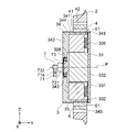
- FIG. FIG. 2 is a cross-sectional view taken along line II-II of FIG. 1;
- FIG. 2 is a cross-sectional view taken along line III-III of FIG. 1;
- FIG. 3 is a front view showing the transmission mechanism of FIG. 2;
- FIG. 2 is a perspective view showing a first elastic plate of FIG. 1;
- FIG. 2 is a perspective view showing a state in which the first elastic plate of FIG. 1 is fixed to a tire;
- FIG. 2 is a perspective view showing a second elastic plate of FIG. 1;
- 2 is a perspective view showing a state in which a second elastic plate of FIG. 1 is fixed to an intermediate member;
- FIG. 2 is a schematic diagram showing a wheel device model obtained by modeling the wheel device of FIG. 1;
- FIG. 2 is a front view showing a state in which the wheel device of FIG. 1 moves on rails;
- FIG. 11 is a schematic diagram showing a wheel device model obtained by modeling the wheel device of FIG. 10;
- FIG. 11 is a front view showing the state of the wheel device when the tire is in a different rotational position from the tire shown in FIG. 10 and receives an impact force from the rail;
- FIG. 13 is a schematic diagram showing a wheel device model obtained by modeling the wheel device of FIG. 12;
- FIG. 10 is a schematic explanatory diagram showing changes in the state of the wheel device when the wheel device of FIG.
- FIG. 9 moves while rotating on the rail; 4 is a graph showing the relationship between the rotation speed R [Hz] and the time t [sec] of each wheel device of Comparative Example A1, Example B1, and Example C1 in numerical analysis.
- 10 is a graph showing the relationship between displacement D1 [mm] in the Z-axis direction of the main body of Comparative Example A1 and time t [sec] in numerical analysis.
- 10 is a graph showing the relationship between displacement D1 [mm] in the Z-axis direction of the main body of Example B1 and time t [sec] in numerical analysis.
- 10 is a graph showing the relationship between displacement D1 [mm] in the Z-axis direction of the main body of Example C1 and time t [sec] in numerical analysis.
- FIG. 5 is a cross-sectional view showing a wheel device according to Embodiment 2;
- FIG. 11 is a cross-sectional view showing a wheel device according to Embodiment 3;
- FIG. 11 is a front view showing a wheel device according to Embodiment 4;
- FIG. 22 is a cross-sectional view along line XXII-XXII of FIG. 21;
- FIG. 11 is a cross-sectional view showing a wheel device according to Embodiment 5;
- FIG. 11 is a cross-sectional view showing a wheel device according to Embodiment 6;
- FIG. 11 is a cross-sectional view showing a wheel device according to Embodiment 7;
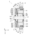
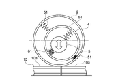
- FIG. 1 is a front view showing a wheel device according to Embodiment 1.
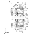
- FIG. 2 is a cross-sectional view along line II-II of FIG.
- FIG. 3 is a cross-sectional view along line III-III of FIG.
- the wheel device 1 has a tire 2 , a main body 3 , an intermediate member 4 , a first connecting structure portion 5 , a second connecting structure portion 6 , and a damping structure portion 7 .
- a railroad vehicle wheel device provided on a vehicle body of a railroad vehicle is used as the wheel device 1 .
- the tire 2 has an annular shape centered on the axis P. Moreover, the inner peripheral surface 21 of the tire 2 is a cylindrical surface centered on the axis P. As shown in FIG.
- the tire 2 is made of metal such as iron.
- the wheel device 1 is placed on the rail while the outer peripheral surface of the tire 2 is in contact with the rail. A wheel device 1 mounted on a rail moves along the rail according to the rotation of the tire 2. - ⁇
- the wheel device 1 is arranged with the axis P of the tire 2 aligned with the Y-axis in the XYZ orthogonal coordinate system, which is a fixed coordinate system.
- the XYZ orthogonal coordinate system is set such that the Z-axis direction is the vertical direction and the Y-axis direction is the width direction of the vehicle body.
- the vertical direction upper side is the plus side.
- the inner side in the width direction of the vehicle body is the plus side.
- the main body 3 is arranged inside the tire 2 .
- the axis of the main body 3 coincides with the axis P of the tire 2 in a natural state in which no load such as vehicle weight is applied to the wheel device 1 . That is, the main body 3 is arranged coaxially with the tire 2 .
- the direction along the axis P of the tire 2 is the axial direction of the tire 2, as shown in FIGS. larger than the dimension of the tire 2 in the direction.
- the main body 3 has a fixed frame 31, a main shaft 32, a main body electric motor 33, a rotating frame 34, and a transmission mechanism 35, as shown in FIGS.
- the fixed frame 31 is fixed to the vehicle body of the railway vehicle.
- the fixed frame 31 is a plate-like member perpendicular to the axis of the main body 3 .
- a through hole 311 is provided in the fixed frame 31 .
- the main shaft 32 is arranged coaxially with the axis of the main body 3 .
- the main shaft 32 also has a first end 321 and a second end 322 .
- the first end 321 is located on the positive side in the Y-axis direction relative to the second end 322 .
- the first end 321 is arranged in the through hole 311 .
- the first end 321 is rotatably attached to the fixed frame 31 via a bearing 301 fitted in the through hole 311 .
- the main body electric motor 33 and the transmission mechanism 35 are arranged between the first end portion 321 and the second end portion 322 in the direction along the axis of the main body 3, ie, the Y-axis direction.
- the body electric motor 33 is arranged between the fixed frame 31 and the transmission mechanism 35 .
- the main body electric motor 33 has a rotor 331 and an annular stator 332 as an armature surrounding the outer circumference of the rotor 331 . Therefore, the main body electric motor 33 is an inner rotor type electric motor.
- the respective axes of the rotor 331 and stator 332 are aligned with the axis of the main body 3 .
- the rotor 331 is fixed to the intermediate portion of the main shaft 32 by shrink fitting or the like.
- the intermediate portion of the main shaft 32 is the portion of the main shaft 32 located between the first end 321 and the second end 322 .
- the stator 332 is fixed to the fixed frame 31.
- the rotor 331 rotates integrally with the main shaft 32 about the axis of the main body 3 with respect to the stationary frame 31 and the stator 332 .
- the main body electric motor 33 generates torque for rotating the rotating frame 34 .
- the rotating frame 34 is arranged coaxially with the axis of the main body 3 as a main body rotating part. Further, the rotating frame 34 is arranged in a state of covering the main body electric motor 33 and the transmission mechanism 35 .
- the rotating frame 34 has a cylindrical portion 341 and a rotating plate portion 342 fixed to the cylindrical portion 341 .
- the cylindrical portion 341 surrounds the main body electric motor 33 and the transmission mechanism 35 .
- An outer peripheral surface 344 of the cylindrical portion 341 is a cylindrical surface centered on the axis of the main body 3 .
- the outer diameter of the cylindrical portion 341 is smaller than the inner diameter of the tire 2 .
- Cylindrical portion 341 is rotatably attached to stator 332 via bearing 302 fitted to the outer peripheral surface of stator 332 .
- the rotating plate portion 342 is arranged at a position closer to the second end portion 322 than the speed change mechanism 35, that is, on the minus side of the speed change mechanism 35 in the Y-axis direction. Also, the rotating plate portion 342 is perpendicular to the axis of the main body 3 .
- the rotary plate portion 342 is provided with a through hole 343 through which the main shaft 32 is passed.
- the rotating plate portion 342 is rotatably attached to the main shaft 32 via a bearing 303 fitted in the through hole 343 .
- the rotating frame 34 is rotatable about the axis of the main body 3 with respect to each of the stationary frame 31 , the stator 332 and the main shaft 32 .
- the transmission mechanism 35 is arranged between the main body electric motor 33 and the rotating plate portion 342 . Further, the transmission mechanism 35 transmits the torque of the main body electric motor 33 to the rotating frame 34 so that the rotating speed of the rotating frame 34 becomes half the rotating speed of the rotor 331 . As a result, the rotation frame 34 rotates in the same direction as the rotation direction of the rotor 331 at half the rotation speed of the rotor 331 by power supply to the stator 332 .
- the transmission mechanism 35 is a planetary gear mechanism having a sun gear 351 , an internal gear 352 and a plurality of planetary gears 353 .
- FIG. 4 is a front view showing the transmission mechanism 35 of FIG.
- the sun gear 351 is fixed to the intermediate portion of the main shaft 32 by shrink fitting or the like. As a result, the sun gear 351 rotates integrally with the main shaft 32 and the rotor 331 about the axis of the main body 3 .
- the internal gear 352 is an annular gear surrounding the sun gear 351 .
- the internal gear 352 is arranged coaxially with the axis of the main body 3 .
- the internal gear 352 is fixed to the stator 332 . Accordingly, when the main shaft 32 rotates with respect to the stator 332 , the sun gear 351 rotates with respect to the internal gear 352 .
- the outer diameter of the internal gear 352 is the same as the outer diameter of the stator 332, as shown in FIGS.
- the cylindrical portion 341 of the rotating frame 34 is rotatably attached to the internal gear 352 via a bearing 304 fitted on the outer peripheral surface of the internal gear 352, as shown in FIGS.
- ball bearings are used as the bearings 301-304.
- the bearings 301-304 are not limited to ball bearings, and may be radial bearings, for example.
- Each planetary gear 353 is arranged between the sun gear 351 and the internal gear 352 .
- the number of planetary gears 353 in the transmission mechanism 35 is four.
- Each planetary gear 353 meshes with the sun gear 351 and the internal gear 352 respectively.
- Each planetary gear 353 has a gear shaft 353a, a first gear portion 353b, and a second gear portion 353c.
- the axis of the gear shaft 353a coincides with the axis of the planetary gear 353.
- the gear shaft 353 a is arranged parallel to the axis of the main body 3 .
- the gear shaft 353a is rotatably attached to the rotating plate portion 342 of the rotating frame 34. As shown in FIG. Thereby, the rotation speed of the rotating frame 34 matches the revolution speed of each planetary gear 353 with respect to the sun gear 351 .
- the rotating frame 34 rotates with each planetary gear 353 about the axis of the main body 3 while synchronizing with the revolution speed of each planetary gear 353 with respect to the sun gear 351 .
- Each of the first gear portion 353b and the second gear portion 353c is an external gear having a plurality of teeth provided on the outer peripheral portion.
- the first gear portion 353b and the second gear portion 353c are fixed to the gear shaft 353a.
- the first gear portion 353b is coaxially fixed to the second gear portion 353c.
- the gear shaft 353a, the first gear portion 353b, and the second gear portion 353c rotate together around the axis of the planetary gear 353.
- the first gear portion 353b and the second gear portion 353c are adjacent to each other in the axial direction of the gear shaft 353a.
- the first gear portion 353b is positioned closer to the rotating plate portion 342 than the second gear portion 353c, that is, is positioned on the minus side in the Y-axis direction of the second gear portion 353c.
- the first gear portion 353b may be positioned closer to the main body electric motor 33 than the second gear portion 353c, that is, on the positive side in the Y-axis direction of the second gear portion 353c.
- the first gear portion 353b meshes with the internal gear 352.
- the second gear portion 353 c meshes with the sun gear 351 .
- the number of teeth of the first gear portion 353b and the number of teeth of the second gear portion 353c are different from each other. In this embodiment, the number of teeth of the first gear portion 353b is greater than the number of teeth of the second gear portion 353c.
- the sun gear 351, the internal gear 352, the first gear portion 353b, and the second gear portion 353c are adjusted so that the rotation speed of the rotating frame 34 is half the rotation speed of the main shaft 32.
- Each number of teeth is determined. That is, in the transmission mechanism 35, the sun gear 351, the internal gear 352, the first gear portion 353b, and the second gear are arranged so that the speed transmission ratio of the rotation speed of the rotating frame 34 to the rotation speed of the main shaft 32 is 1/2.
- the number of teeth of each of the portions 353c is determined.
- the number of teeth of the sun gear 351 is z1
- the number of teeth of the first gear portion 353b is z2
- the number of teeth of the second gear portion 353c is z3
- the number of teeth of the internal gear 352 is z4.
- the speed transmission ratio i of the number of revolutions of the rotating frame 34 to the number of revolutions of the main shaft 32 is expressed by the following equation (1).
- the number of teeth of the first gear portion 353b and the number of teeth of the second gear portion 353c are different from each other.
- the number of teeth z1 of the sun gear 351 can be made different from the number of teeth z4 of the internal gear 352, and the speed transmission ratio i of the number of rotations of the rotating frame 34 to the number of rotations of the main shaft 32 can be reduced to 1/2. It is possible to realize a transmission mechanism 35 that
- the intermediate member 4 is an annular member surrounding the rotating frame 34, as shown in FIG.
- the intermediate member 4 is arranged inside the tire 2 . That is, the tire 2 is an annular member surrounding the intermediate member 4 .
- the wheel device 1 is an in-wheel motor in which the main body 3 including the main body electric motor 33 is arranged inside the tire 2 .
- the intermediate member 4 is a separate member from each of the tire 2 and the main body 3 .
- the intermediate member 4 is arranged at the same position as the tire 2 in the Y-axis direction, that is, in the axial direction of the tire 2 .
- the axis of the intermediate member 4 coincides with the axis P of the tire 2 in a natural state in which no load such as vehicle body weight is applied to the wheel device 1 . That is, the intermediate member 4 is arranged coaxially with the tire 2 .
- Each of the inner peripheral surface 41 and the outer peripheral surface 42 of the intermediate member 4 is a cylindrical surface centered on the axis of the intermediate member 4 .
- the outer diameter of the intermediate member 4 is smaller than the inner diameter of the tire 2 .
- the inner diameter of the intermediate member 4 is larger than the outer diameter of the rotating frame 34 .
- the annular intermediate member 4 is thus arranged in the space between the tire 2 and the body 3 .
- the first connecting structure portion 5 is provided between the tire 2 and the intermediate member 4 .
- the first connecting structure portion 5 also has a pair of first elastic plates 51 as first elastic bodies that connect the tire 2 and the intermediate member 4 to each other.
- the second connecting structure part 6 is provided between the intermediate member 4 and the rotating frame 34 .
- the second connection structure 6 also has a pair of second elastic plates 61 as second elastic bodies that connect the intermediate member 4 and the rotating frame 34 to each other.
- each of the pair of first elastic plates 51 is arranged at a position that intersects the first imaginary straight line. It is The first imaginary straight line matches the straight line along the X-axis direction. Also, the pair of first elastic plates 51 are arranged at positions opposite to each other with respect to the axis of the intermediate member 4 in the direction along the first imaginary straight line, that is, the X-axis direction.
- FIG. 5 is a perspective view showing the first elastic plate 51 of FIG.
- Each first elastic plate 51 is a rectangular flat plate.
- the direction along the short side of the rectangle of the first elastic plate 51 is the width direction of the first elastic plate 51 .
- the direction along the long side of the rectangle of the first elastic plate 51 is the longitudinal direction of the first elastic plate 51 .
- the direction orthogonal to both the width direction and the longitudinal direction of the first elastic plate 51 is defined as the thickness direction of the first elastic plate 51 .
- each first elastic plate 51 is arranged orthogonally to the first imaginary straight line. That is, the thickness direction of each first elastic plate 51 coincides with the direction along the first imaginary straight line, that is, the X-axis direction. Also, the width direction of each first elastic plate 51 coincides with the axial direction of the tire 2, that is, the Y-axis direction. Thereby, the longitudinal direction of each first elastic plate 51 coincides with the Z-axis direction, which is orthogonal to both the X-axis direction and the Y-axis direction. That is, the pair of first elastic plates 51 are arranged parallel to the YZ plane perpendicular to the X-axis direction.
- each first elastic plate 51 Both longitudinal ends 511 of each first elastic plate 51 are fixed to the inner peripheral surface 21 of the tire 2 as a pair of fixing ends.
- the longitudinal intermediate portion 512 of each first elastic plate 51 is fixed to the outer peripheral surface 42 of the intermediate member 4 as a single fixing plate portion.
- the rigidity in the direction orthogonal to the thickness direction of the first elastic plate 51 is the rigidity in the thickness direction of the first elastic plate 51, that is, the out-of-plane rigidity of the first elastic plate 51. is sufficiently higher than As a result, when the tire 2 and the intermediate member 4 are connected via the first elastic plate 51 , the tire 2 and the intermediate member 4 are rigidly connected in the direction perpendicular to the thickness direction of the first elastic plate 51 . can be considered to be equivalent to the state in which
- the first elastic plate 51 elastically deforms in the thickness direction of the first elastic plate 51 . It is possible.
- the intermediate member 4 is movable with respect to the tire 2 in the direction along the first imaginary straight line, i.e., in the X-axis direction, by elastically deforming the first elastic plates 51 in the thickness direction of the first elastic plates 51. It's becoming That is, each first elastic plate 51 connects the intermediate member 4 and the tire 2 to each other so that the intermediate member 4 can move relative to the tire 2 along the first imaginary straight line.
- the tire 2 and the intermediate member 4 have a degree of freedom that allows relative movement only in the direction along the first imaginary straight line, that is, in the X-axis direction, due to the elastic deformation of each first elastic plate 51 in the thickness direction. ing.
- an outer peripheral plane portion 421 is provided at a position where the longitudinal intermediate portion 512 of each first elastic plate 51 is fixed as a single fixing plate portion on the outer peripheral surface 42 of the intermediate member 4. are formed respectively.
- two outer peripheral plane portions 421 are formed on the outer peripheral surface 42 of the intermediate member 4 .
- Each outer peripheral plane portion 421 is a plane portion orthogonal to the direction along the first imaginary straight line, that is, the X-axis direction.
- the longitudinal intermediate portion 512 of the first elastic plate 51 is fixed to the outer peripheral surface 42 of the intermediate member 4 in a state in which the surface of the first elastic plate 51 perpendicular to the thickness direction is in contact with the outer peripheral flat portion 421 without any gap.
- a fixing method for fixing the longitudinal intermediate portion 512 of the first elastic plate 51 to the outer peripheral surface 42 of the intermediate member 4 a fixing method using screws, bolts, welding, adhesives, or the like is used.
- a pair of stepped portions 211 are formed on the inner peripheral surface 21 of the tire 2 at positions where the longitudinal direction end portions 511 of each first elastic plate 51 are fixed as a pair of fixing end portions. Therefore, the number of pairs of steps 211 equal to the number of the first elastic plates 51 is formed on the inner peripheral surface 21 of the tire 2 . In this embodiment, two pairs of stepped portions 211 are formed on the inner peripheral surface 21 of the tire 2 .
- FIG. 6 is a perspective view showing a state where the first elastic plate 51 of FIG. 1 is fixed to the tire 2.
- Both ends 511 in the longitudinal direction of the first elastic plate 51 are fitted in the pair of stepped portions 211 respectively.
- the pair of stepped portions 211 face each other in the circumferential direction of the tire 2 .
- Each of the pair of stepped portions 211 is formed by a stepped portion bottom surface 211a orthogonal to the direction along the first imaginary straight line, that is, the X-axis direction, and a stepped portion end surface 211b extending from the stepped portion bottom surface 211a toward the inside of the tire 2. It is configured.
- a step end surface 211b of each of the pair of step portions 211 is a plane parallel to a plane including the axis of the intermediate member 4 and the first imaginary straight line. Accordingly, the step portion end surfaces 211b of the pair of step portions 211 are orthogonal to the Z-axis direction.
- the pair of stepped portions 211 are formed on the inner peripheral surface 21 of the tire 2 such that the two stepped portion end surfaces 211b face each other in the Z-axis direction.
- Both ends 511 in the longitudinal direction of the first elastic plate 51 are arranged so that the surface of the first elastic plate 51 perpendicular to the thickness direction is in contact with the bottom surface 211a of the stepped portion without gaps, and the end faces in the longitudinal direction of the first elastic plate 51 are in contact with the stepped portion. It is fixed to the inner peripheral surface 21 of the tire 2 while being in contact with the end surface 211b without any gap.
- fixing methods such as screws, bolts, welding, and adhesives are used.
- each of the pair of second elastic plates 61 is arranged at a position that intersects the second virtual straight line.
- a straight line perpendicular to both the first virtual straight line and the axis of the intermediate member 4 is defined as the second virtual straight line. That is, in this embodiment, the second imaginary straight line matches the straight line along the Z-axis direction.
- the pair of second elastic plates 61 are arranged at positions opposite to each other with respect to the axis P of the tire 2 in the direction along the second imaginary straight line, that is, in the Z-axis direction.
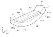
- FIG. 7 is a perspective view showing the second elastic plate 61 of FIG.
- Each second elastic plate 61 is a rectangular flat plate.
- the direction along the short side of the rectangle of the second elastic plate 61 is the width direction of the second elastic plate 61 .
- the direction along the long side of the rectangle of the second elastic plate 61 is the longitudinal direction of the second elastic plate 61 .
- the direction orthogonal to both the width direction and the longitudinal direction of the second elastic plate 61 is the thickness direction of the second elastic plate 61 .
- Each second elastic plate 61 is arranged orthogonally to the second imaginary straight line, as shown in FIG. That is, the thickness direction of each second elastic plate 61 coincides with the direction along the second imaginary straight line, that is, the Z-axis direction. Further, the width direction of each second elastic plate 61 coincides with the axial direction of the tire 2, that is, the Y-axis direction. Thereby, the longitudinal direction of each second elastic plate 61 coincides with the X-axis direction, which is orthogonal to both the Y-axis direction and the Z-axis direction. That is, the pair of second elastic plates 61 are arranged parallel to the XY plane perpendicular to the Z-axis direction.
- Both longitudinal ends 611 of each second elastic plate 61 are fixed to the inner peripheral surface 41 of the intermediate member 4 as a pair of fixing ends.
- a longitudinal intermediate portion 612 of each second elastic plate 61 is fixed to the outer peripheral surface 344 of the rotating frame 34 as a single fixing plate portion.
- the rigidity in the direction perpendicular to the thickness direction of the second elastic plate 61 is equal to the rigidity in the thickness direction of the second elastic plate 61, that is, the out-of-plane rigidity of the second elastic plate 61. is sufficiently higher than As a result, in a state in which the intermediate member 4 and the rotating frame 34 are connected via the second elastic plate 61, the intermediate member 4 and the rotating frame 34 are separated from each other in the direction perpendicular to the thickness direction of the second elastic plate 61. It can be considered equivalent to a rigidly coupled state.
- each second elastic plate 61 connects the intermediate member 4 and the rotating frame 34 to each other so that the intermediate member 4 can move relative to the main body 3 along the second imaginary straight line.
- the intermediate member 4 and the main body 3 have a degree of freedom that allows relative movement only in the direction along the second imaginary straight line, that is, in the Z-axis direction, due to the elastic deformation of each second elastic plate 61 in the thickness direction. ing.
- An outer peripheral plane portion 345 is formed at a position where the longitudinal intermediate portion 612 of each second elastic plate 61 is fixed as a single fixing plate portion on the outer peripheral surface 344 of the rotating frame 34 .
- two outer peripheral plane portions 345 are formed on the outer peripheral surface 344 of the rotating frame 34 .
- Each outer peripheral plane portion 345 is a plane portion perpendicular to the direction along the second imaginary straight line, that is, the Z-axis direction.
- the longitudinal intermediate portion 612 of the second elastic plate 61 is fixed to the outer peripheral surface 344 of the rotating frame 34 in a state in which the surface of the second elastic plate 61 perpendicular to the thickness direction is in contact with the outer peripheral flat portion 345 without any gap.
- a fixing method for fixing the longitudinal intermediate portion 612 of the second elastic plate 61 to the outer peripheral surface 344 of the rotating frame 34 a fixing method using screws, bolts, welding, adhesives, or the like is used.
- a pair of stepped portions 411 are formed on the inner peripheral surface 41 of the intermediate member 4 at positions where the longitudinal direction end portions 611 of each of the second elastic plates 61 are fixed as a pair of fixing end portions. . Therefore, the inner peripheral surface 41 of the intermediate member 4 is formed with a pair of steps 411 equal in number to the second elastic plates 61 . In this embodiment, two pairs of stepped portions 411 are formed on the inner peripheral surface 41 of the intermediate member 4 .
- FIG. 8 is a perspective view showing a state in which the second elastic plate 61 of FIG. 1 is fixed to the intermediate member 4.
- FIG. Both ends 611 in the longitudinal direction of the second elastic plate 61 are fitted in the pair of stepped portions 411 respectively.
- the pair of stepped portions 411 face each other in the circumferential direction of the intermediate member 4 .
- Each of the pair of stepped portions 411 includes a stepped portion bottom surface 411a orthogonal to the direction along the second imaginary straight line, that is, the Z-axis direction, and a stepped portion end surface 411b extending from the stepped portion bottom surface 411a toward the inner side of the intermediate member 4. It is composed by
- a step end surface 411b of each of the pair of step portions 411 is a plane parallel to a plane including the axis of the intermediate member 4 and the second imaginary straight line. Accordingly, the step portion end surfaces 411b of the pair of step portions 411 are orthogonal to the X-axis direction.
- the pair of stepped portions 411 are formed on the inner peripheral surface 41 of the intermediate member 4 with the two stepped end surfaces 411b facing each other in the X-axis direction.
- Both ends 611 in the longitudinal direction of the second elastic plate 61 are in contact with the bottom surface 411a of the stepped portion without any gap between the surfaces perpendicular to the thickness direction of the second elastic plate 61, and the end faces in the longitudinal direction of the second elastic plate 61 contact the stepped portion. It is fixed to the inner peripheral surface 41 of the intermediate member 4 while being in contact with the end surface 411b without any gap.
- a fixing method using screws, bolts, welding, adhesives, or the like is used as a method for fixing the longitudinal direction end portions 611 of the second elastic plate 61 to the inner peripheral surface 41 of the intermediate member 4.
- the damping structure 7 is provided on the main body 3 as shown in FIGS. Also, the damping structure 7 has a weight 71 as a balancer.
- the weight 71 is fixed to the second end 322 of the main shaft 32 .
- the weight 71 is arranged at a position farther from the transmission mechanism 35 than the position of the rotary plate portion 342 , that is, at the negative side of the rotary frame 34 in the Y-axis direction.
- the weight 71 rotates integrally with the main shaft 32 and the rotor 331 around the axis of the main body 3 . That is, the centerline of rotation of the weight 71 coincides with the axis of the main body 3 . Also, the number of revolutions of the weight 71 is the same as the number of revolutions of the main shaft 32 and the rotor 331 . As a result, the weight 71 rotates in the same direction as the rotational direction of the rotating frame 34 at twice the rotating speed of the rotating frame 34 .
- the weight 71 protrudes from the main shaft 32 in a specific radial direction orthogonal to the centerline of rotation of the weight 71 .
- the position of the center of gravity 71 a of the weight 71 is set at a position away from the rotation center line of the weight 71 in the direction orthogonal to the rotation center line of the weight 71 .
- the position of the center of gravity 71a of weight 71 is set at a position away from the center line of rotation of weight 71 in the direction along the second imaginary straight line.
- the center of gravity 71a of the weight 71 moves on a circle centered on the rotation center line of the weight 71 as the weight 71 rotates.
- the position of the center of gravity 71a of the weight 71 is on the negative side of the rotation center line of the weight 71 in the Z-axis direction in the state of FIG. is placed so that the position of Therefore, when the thickness direction of each of the pair of second elastic plates 61 coincides with the Z-axis direction and the pair of second elastic plates 61 are positioned on the Z-axis, the position of the center of gravity 71a of the weight 71 is It is positioned on the negative side in the Z-axis direction with respect to the rotation center line of the weight 71 . That is, when the direction along the second imaginary straight line in the wheel device 1 coincides with the vertical direction, the position of the center of gravity 71 a of the weight 71 is positioned below the rotation center line of the weight 71 .
- FIG. 9 is a schematic diagram showing a wheel device model obtained by modeling the wheel device 1 of FIG. Due to the elastic deformation of the pair of second elastic plates 61, the intermediate member 4 is movable with respect to the main body 3 in the direction along the second imaginary straight line. Movement of the intermediate member 4 with respect to the main body 3 in directions other than the direction along the second imaginary straight line is restricted by the in-plane rigidity of the pair of second elastic plates 61 .
- the intermediate member 4 Due to the elastic deformation of the pair of first elastic plates 51, the intermediate member 4 is movable with respect to the tire 2 in the direction along the first imaginary straight line. Movement of the intermediate member 4 with respect to the tire 2 in directions other than the direction along the first imaginary straight line is restricted by the in-plane rigidity of the pair of first elastic plates 51 .
- a vibration system with two translational degrees of freedom is configured in which the intermediate member 4 can freely move relative to the main body 3 and the tire 2 within the XZ plane including the first virtual straight line and the second virtual straight line. ing.
- each of the first elastic plates 51 and the second elastic plates 61 is in-plane rigidity in the circumferential direction of the tire 2 . Therefore, elastic deformation of each of the first elastic plates 51 and the second elastic plates 61 is restricted in the circumferential direction of the tire 2 . Accordingly, in the circumferential direction of the tire 2, the connection state of the intermediate member 4 to the tire 2 and the connection state of the intermediate member 4 to the rotating frame 34 can be regarded as a rigid connection state. Therefore, the number of revolutions of the tire 2 is the same as the number of revolutions of the intermediate member 4 . Further, the number of rotations of the intermediate member 4 is the same as the number of rotations of the rotating frame 34 .
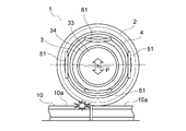
- FIG. 10 is a front view showing the state in which the wheel device 1 of FIG. 1 moves on the rail.
- FIG. 11 is a schematic diagram showing a wheel device model that models the wheel device 1 of FIG. When the wheel device 1 is placed on the rail 10 , the outer peripheral surface of the tire 2 is in contact with the rail 10 . The wheel device 1 moves on the rail 10 as the tire 2 rotates.
- the torque of the main body electric motor 33 transmitted to the rotating frame 34 is transmitted from the rotating frame 34 to the intermediate member 4 via the pair of second elastic plates 61 .
- the direction of the torque transmitted from the rotating frame 34 to each second elastic plate 61 coincides with the direction of the in-plane rigidity of each second elastic plate 61 .
- the elastic deformation of each second elastic plate 61 is restricted, and the torque of the rotating frame 34 is effectively transmitted to the intermediate member 4 .
- the torque transmitted to the intermediate member 4 is transmitted to the tire 2 via the pair of first elastic plates 51 .
- the direction of torque transmitted from the intermediate member 4 to each first elastic plate 51 coincides with the direction of in-plane rigidity of each first elastic plate 51 .
- the elastic deformation of each first elastic plate 51 is restricted, and the torque transmitted to the intermediate member 4 is effectively transmitted to the tire 2 .
- the tire 2 rotates. Therefore, in the wheel device 1 , when the rotating frame 34 rotates, each of the tire 2 and the intermediate member 4 rotates in the same direction as the rotating frame 34 rotates.
- the rail 10 is configured by continuously connecting a plurality of unit rails 10a.
- a step may occur at the seam between two unit rails 10a adjacent to each other.
- the tire 2 receives impact force from the rail 10 when the wheel device 1 passes through the joint between the two unit rails 10a.
- each second elastic plate 61 causes an intermediate The member 4 moves relative to the main body 3 only in the direction along the second imaginary straight line. As a result, the impact force received by the tire 2 is absorbed by the pair of second elastic plates 61 and is less likely to be transmitted to the main body 3 .
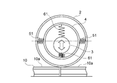
- FIG. 12 is a front view showing the state of the wheel device 1 when the tire 2 receives an impact force from the rail 10 at a rotational position different from that of the tire 2 in FIG.
- FIG. 13 is a schematic diagram showing a wheel device model that models the wheel device 1 of FIG.
- the intermediate member 4 moves relative to the tire 2 in the direction along the first imaginary straight line
- the intermediate member 4 moves relative to the main body 3 in the direction along the second imaginary straight line.
- each first elastic plate 51 is elastically deformed.
- each second elastic plate 61 is elastically deformed. As a result, the impact force applied to the tire 2 is absorbed by each of the first elastic plates 51 and the second elastic plates 61 and is less likely to be transmitted to the main body 3 .
- FIG. 14A and 14B are schematic explanatory diagrams showing changes in the state of the wheel device 1 when the wheel device 1 in FIG. 9 moves while rotating on the rail 10.
- the direction along the first imaginary straight line is defined as the first direction ⁇
- the direction along the second imaginary straight line is defined as the second direction ⁇ .
- FIG. 14 shows changes in the state of the wheel device 1 from the state in which the second direction ⁇ coincides with the Z-axis direction to the state in which the second direction ⁇ coincides with the X-axis direction.
- the intermediate member 4 swings 180 degrees with respect to the tire 2 and the main body 3 while the wheel device 1 rotates 90 degrees. That is, the intermediate member 4 whirles at twice the rotational frequency of the wheel device 1 .
- the intermediate member 4 whirles, a centrifugal force is generated in the intermediate member 4, so that the entire wheel device 1 tends to vibrate.
- the vibration of the entire wheel device 1 is suppressed by the movement of the weight 71 in the damping structure 7 .
- the center of gravity 71a of the weight 71 is located on the negative side of the Z-axis direction, that is, below the rotation center line of the weight 71 . Further, the weight 71 rotates in the same direction as the rotational direction of the rotating frame 34 at twice the rotating speed of the rotating frame 34 . Therefore, the weight 71 rotates 180° until the wheel device 1 rotates 90° from the initial state until the second direction ⁇ coincides with the X-axis direction, and the center of gravity 71a of the weight 71 becomes the center of rotation of the weight 71. It moves to the plus side in the Z-axis direction, that is, upwards from the line. As a result, a centrifugal force acts on the weight 71 toward the positive side in the Z-axis direction.
- the eccentric distance of the weight 71 is the distance from the center line of rotation of the weight 71 to the center of gravity 71 a of the weight 71 .
- M be the mass of the intermediate member 4
- ⁇ be the rotational angular velocity of the wheel device 1
- m be the mass of the weight 71
- L be the eccentric distance of the weight 71 .
- the centrifugal force acting on the intermediate member 4 due to the whirling of the vibration system including the intermediate member 4 is expressed by the following formula (3).
- the condition under which the vibration due to the whirling of the intermediate member 4 is most suppressed is the condition where the equations (3) and (4) are balanced. Therefore, the condition under which the vibration due to whirling of the intermediate member 4 is most suppressed is represented by the following equation (5).
- the product of the eccentric distance L of the weight 71 and the mass m of the weight 71 is 1/4 times the product of the vertical displacement D of the intermediate member 4 and the mass M of the intermediate member 4 when the tire 2 rotates. , the vibration due to whirling of the intermediate member 4 is effectively suppressed.
- the product of the eccentric distance L of the weight 71 and the mass m of the weight 71 is the product of the displacement D of the intermediate member 4 in the vertical direction when the tire 2 rotates and the mass M of the intermediate member 4. agrees with 1/4 times.
- the displacement D1 in the Z-axis direction of the main body 3 when the rotational speed R [Hz] of the wheel device 1 was changed linearly from 0 [Hz] to 20 [Hz] was obtained by numerical analysis.
- FIG. 15 is a graph showing the relationship between the rotation speed R [Hz] and the time t [sec] of each of the wheel devices of Comparative Example A1, Example B1, and Example C1 in numerical analysis.
- FIG. 16 is a graph showing the relationship between the displacement D1 [mm] in the Z-axis direction of the main body 3 of Comparative Example A1 and the time t [sec] in numerical analysis.
- FIG. 17 is a graph showing the relationship between the displacement D1 [mm] in the Z-axis direction of the main body 3 of Example B1 and the time t [sec] in numerical analysis.
- FIG. 18 is a graph showing the relationship between the displacement D1 [mm] in the Z-axis direction of the main body 3 of Example C1 and the time t [sec] in numerical analysis.
- each first elastic plate 51 is arranged perpendicular to the first imaginary straight line perpendicular to the axis of the intermediate member 4.
- Each second elastic plate 61 is arranged orthogonally to a second imaginary straight line different from the first imaginary straight line. Therefore, the rigidity of each of the first elastic plates 51 and the second elastic plates 61 in the circumferential direction of the tire 2 can be increased. As a result, the elastic deformation of each of the first elastic plates 51 and the second elastic plates 61 in the rotation direction of the tire 2 can be restricted, and unnecessary vibration of the tire 2 with respect to the main body 3 is suppressed in the rotation direction of the tire 2. can be prevented from occurring. Therefore, torque can be transmitted from the main body 3 to the tire 2 more reliably.
- the main body 3 can be moved with respect to the tire 2 while at least one of the first elastic plate 51 and the second elastic plate 61 is elastically deformed. This allows at least one of the first elastic plate 51 and the second elastic plate 61 to absorb the impact force applied to the tire 2 . Therefore, the impact force transmitted from the tire 2 to the main body 3 can be suppressed.
- each first elastic plate 51 and each second elastic plate 61 can be arranged evenly in the circumferential direction of the tire 2 .
- the force for suppressing the impact force applied to the tire 2 can be equalized in the circumferential direction of the tire 2 .
- the axis of the intermediate member 4 is located between the pair of first elastic plates 51 and between the pair of second elastic plates 61 . Therefore, the state in which the intermediate member 4 is connected to the tire 2 and the state in which the main body 3 is connected to the intermediate member 4 can be stabilized. As a result, occurrence of failure of the wheel device 1 can be more reliably suppressed, and reliability of the wheel device 1 can be improved.
- Both longitudinal ends 511 of the first elastic plate 51 are fixed to the tire 2 , and a longitudinal intermediate part 512 of the first elastic plate 51 is fixed to the intermediate member 4 . Therefore, the first elastic plate 51 can be securely fixed to each of the tire 2 and the intermediate member 4 while allowing elastic deformation of the first elastic plate 51 in the thickness direction.
- Both longitudinal ends 611 of the second elastic plate 61 are fixed to the intermediate member 4 , and a longitudinal intermediate part 612 of the second elastic plate 61 is fixed to the rotating frame 34 of the main body 3 . Therefore, the second elastic plate 61 can be securely fixed to each of the intermediate member 4 and the rotating frame 34 while allowing elastic deformation of the second elastic plate 61 in the thickness direction.
- the longitudinal ends 511 of the first elastic plate 51 are located at positions where the longitudinal ends 511 of the first elastic plate 51 are fixed as a pair of fixing ends.
- a pair of stepped portions 211 are formed into which are fitted. Therefore, it is possible to more reliably fix the first elastic plate 51 to the tire 2 , and to more reliably prevent displacement of the first elastic plate 51 with respect to the tire 2 .
- both longitudinal ends of the second elastic plate 61 are located at positions where the longitudinal ends 611 of the second elastic plate 61 are fixed as a pair of fixing ends.
- a pair of stepped portions 411 into which the 611 are fitted are formed. Therefore, the second elastic plate 61 can be more reliably fixed to the intermediate member 4 , and displacement of the second elastic plate 61 with respect to the intermediate member 4 can be more reliably prevented.
- the damping structure 7 also has a weight 71 that rotates in the same direction as the rotating frame 34 at twice the rotating speed of the rotating frame 34 . Furthermore, when the direction along the second imaginary straight line coincides with the vertical direction, the center of gravity 71 a of the weight 71 is positioned below the rotation center line of the weight 71 . Therefore, at least part of the excitation force generated by the movement of the intermediate member 4 with respect to the tire 2 and the main body 3 can be canceled by the centrifugal force of the weight 71 . As a result, vibration of the entire wheel device 1 due to whirling of the intermediate member 4 can be suppressed.
- the main body 3 also has a main body electric motor 33 that generates torque for rotating the rotating frame 34 . Therefore, the driving source for rotating the wheel device 1 can be arranged inside the intermediate member 4 . Thereby, size reduction of the wheel apparatus 1 can be achieved.
- the main body 3 also has a transmission mechanism 35 that transmits the torque of the main body electric motor 33 to the rotating frame 34 so that the rotational speed of the rotating frame 34 is half the rotational speed of the rotor 331 .
- the weight 71 rotates integrally with the rotor 331 . Therefore, the number of revolutions of the weight 71 can more reliably be doubled as the number of revolutions of the rotating frame 34 .
- the transmission mechanism 35 is a planetary gear mechanism having a sun gear 351 , an internal gear 352 and a plurality of planetary gears 353 . Therefore, the number of revolutions of the weight 71 can be doubled as the number of revolutions of the rotating frame 34 with a simple configuration. As a result, it is possible to more reliably suppress the occurrence of failures in the wheel device 1, and to improve the reliability of the wheel device 1 more reliably.
- the product of the eccentric distance L of the weight 71 and the mass m of the weight 71 is 1/4 times the product of the displacement D of the intermediate member 4 in the vertical direction and the mass M of the intermediate member 4 when the tire 2 rotates. is consistent with Therefore, the centrifugal force of the weight 71 can effectively cancel the excitation force due to whirling of the intermediate member 4 . As a result, vibration of the entire wheel device 1 can be effectively suppressed.
- the rotation center line of the weight 71 is deviated from the axis of the main body 3 , an unnecessary rotational moment is generated in the weight 71 that does not contribute to suppressing vibration due to whirling of the intermediate member 4 .
- the centerline of rotation of the weight 71 coincides with the axis of the main body 3 .
- generation of unnecessary rotational moment can be suppressed.
- Embodiment 2. 19 is a cross-sectional view showing a wheel device according to Embodiment 2.
- FIG. 19 is a diagram corresponding to FIG. 2 in the first embodiment.
- a rotating plate portion 342 of the rotating frame 34 is rotatably attached to the second end portion 322 of the main shaft 32 via a bearing 303 .
- the main shaft 32 extends from the fixed frame 31 toward the positive side in the Y-axis direction. Accordingly, the first end portion 321 of the main shaft 32 is located inside the fixed frame 31 in the width direction of the vehicle body.
- the weight 71 is fixed to the first end 321 of the main shaft 32 . Therefore, the weight 71 is arranged on the inner side of the fixed frame 31 in the width direction of the vehicle body, that is, on the positive side of the fixed frame 31 in the Y-axis direction.
- the configuration of the weight 71 is the same as that of the first embodiment. As a result, the weight 71 rotates in the same direction as the rotational direction of the rotating frame 34 at twice the rotating speed of the rotating frame 34 . Further, the center of gravity 71a of the weight 71 moves along with the rotation of the weight 71 on a circle having the rotation center line of the weight 71 as the center.
- the center of gravity 71a of the weight 71 is positioned on the negative side of the rotation center line of the weight 71 in the Z-axis direction in a state where the direction along the second imaginary straight line coincides with the Z-axis direction. are arranged so that Therefore, when the direction along the second imaginary straight line in the wheel device 1 coincides with the vertical direction, the position of the center of gravity 71 a of the weight 71 is positioned below the rotation center line of the weight 71 .
- Other configurations in the second embodiment are similar to those in the first embodiment.
- the weight 71 is fixed to the first end portion 321 of the main shaft 32. Therefore, the weight 71 can be arranged on the inner side in the width direction of the vehicle body than the fixed frame 31 fixed to the vehicle body. As a result, it is possible to reduce the size of the wheel device 1 arranged outside the fixed frame 31 in the width direction of the vehicle body. Therefore, the wheel device 1 can be made compact with respect to the limit of the side surface of the vehicle body, and the degree of freedom in designing the wheel device 1 can be improved.
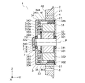
- Embodiment 3. 20 is a cross-sectional view showing a wheel device according to Embodiment 3.
- FIG. 20 is a diagram corresponding to FIG. 2 in the first embodiment.
- a rotating plate portion 342 of the rotating frame 34 is fixed to the second end portion 322 of the main shaft 32 .
- the rotating frame 34 rotates integrally with the main shaft 32 and the rotor 331 around the axis of the main body 3 . Therefore, the rotation frame 34 rotates at the same rotation speed as that of each of the main shaft 32 and the rotor 331 due to the torque of the main body electric motor 33 .
- the damping structure 7 is arranged on the inner side in the width direction of the vehicle body than the main body 3, that is, on the positive side of the main body 3 in the Y-axis direction.
- the damping structure 7 also has a weight 71 and a transmission mechanism 72 .
- the weight 71 is attached to the main shaft 32 via the transmission mechanism 72 .
- the transmission mechanism 72 transmits the torque of the main body electric motor 33 to the weight 71 .
- the transmission mechanism 72 is arranged on the inner side of the main shaft 32 in the width direction of the vehicle body, that is, on the positive side of the main shaft 32 in the Y-axis direction. Further, the speed change mechanism 72 transmits the torque of the main body electric motor 33 to the weight 71 so that the rotation speed of the weight 71 becomes twice the rotation speed of the rotor 331 . Therefore, the weight 71 rotates in the same direction as the rotational direction of the rotating frame 34 by supplying power to the stator 332 at twice the rotational speed of the rotating frame 34 .
- the transmission mechanism 72 has a sun gear 721 , an internal gear 722 , a plurality of planetary gears 723 , a main shaft fixing member 725 and a transmission mechanism output shaft 726 .
- the sun gear 721, the internal gear 722 and the plurality of planetary gears 723 constitute a planetary gear mechanism.
- the configuration of the planetary gear mechanism is the same as that of the transmission mechanism 35 according to the first embodiment.
- the main shaft fixing member 725 is fixed to the first end portion 321 of the main shaft 32 . As a result, the main shaft fixing member 725 rotates integrally with the main shaft 32 and the rotor 331 around the axis of the main body 3 .
- the main shaft fixing member 725 is located on the inner side of the fixed frame 31 in the width direction of the vehicle body, that is, on the positive side of the fixed frame 31 in the Y-axis direction.
- the main shaft fixing member 725 is a disk perpendicular to the axis of the main body 3 .
- the outer diameter of the main shaft fixing member 725 is larger than the outer diameter of the main shaft 32 .
- the sun gear 721 is arranged coaxially with the axis of the main body 3 . Further, the sun gear 721 is located on the inner side of the main shaft fixing member 725 in the width direction of the vehicle body, that is, on the positive side of the main shaft fixing member 725 in the Y-axis direction.
- the internal gear 722 is an annular gear surrounding the sun gear 721 . Accordingly, the internal gear 722 is located on the inner side of the fixed frame 31 in the width direction of the vehicle body, that is, on the positive side of the fixed frame 31 in the Y-axis direction. The internal gear 722 is arranged coaxially with the axis of the main body 3 . Also, the internal gear 722 is fixed to the fixed frame 31 .
- Each planetary gear 723 is arranged between the sun gear 721 and the internal gear 722 . Each planetary gear 723 meshes with the sun gear 721 and the internal gear 722 respectively. Each planetary gear 723 is attached to a main shaft fixing member 725 . The sun gear 721 is supported by being sandwiched between each planetary gear 723 . Each planetary gear 723 revolves around the sun gear 721 around the axis of the main body 3 by rotating the main shaft fixing member 725 integrally with the main shaft 32 and the rotor 331 . The revolution speed of each planetary gear 723 with respect to the sun gear 721 matches the rotational speed of the rotor 331 .
- the sun gear 721 rotates about the axis of the main body 3 with respect to the internal gear 722 while synchronizing with the revolution speed of each planetary gear 723 with respect to the sun gear 721 .
- Each planetary gear 723 has a gear shaft 723a, a first gear portion 723b, and a second gear portion 723c.
- the axis of the gear shaft 723a coincides with the axis of the planetary gear 723.
- the gear shaft 723 a is arranged parallel to the axis of the main body 3 . Further, the gear shaft 723a is rotatably attached to the main shaft fixing member 725. As shown in FIG.
- Each of the first gear portion 723b and the second gear portion 723c is an external gear having a plurality of teeth provided on the outer peripheral portion.
- the first gear portion 723b and the second gear portion 723c are fixed to the gear shaft 723a.
- the first gear portion 723b is coaxially fixed to the second gear portion 723c.
- the gear shaft 723a, the first gear portion 723b, and the second gear portion 723c rotate together around the axis of the planetary gear 723.
- the first gear portion 723b and the second gear portion 723c are adjacent to each other in the axial direction of the gear shaft 723a.
- the first gear portion 723b meshes with the internal gear 722.
- the second gear portion 723c meshes with the sun gear 721. As shown in FIG.
- the number of teeth of the first gear portion 723b and the number of teeth of the second gear portion 723c are different from each other. In this embodiment, the number of teeth of the first gear portion 723b is greater than the number of teeth of the second gear portion 723c.
- the second gear portion 723c is positioned closer to the fixed frame 31 than the first gear portion 723b, that is, is positioned on the minus side in the Y-axis direction of the first gear portion 723b.
- the second gear portion 723c may be positioned farther from the fixed frame 31 than the first gear portion 723b, that is, on the positive side in the Y-axis direction of the first gear portion 723b.
- the transmission mechanism output shaft 726 is fixed to the sun gear 721 .
- the transmission mechanism output shaft 726 protrudes from the sun gear 721 toward the inside in the width direction of the vehicle body, that is, from the sun gear 721 toward the positive side in the Y-axis direction.
- the transmission mechanism output shaft 726 is arranged coaxially with the axis of the main body 3 . As a result, the transmission mechanism output shaft 726 rotates integrally with the sun gear 721 about the axis of the main body 3 .
- the sun gear 721, the internal gear 722, the first gear portion 723b, and the second gear portion 723c are rotated so that the rotation speed of the transmission mechanism output shaft 726 is double the rotation speed of the rotor 331.
- Each number of teeth is determined. That is, in the transmission mechanism 72, the sun gear 721, the internal gear 722, the first gear portion 723b, and the second gear are arranged so that the speed transmission ratio of the rotation speed of the transmission mechanism output shaft 726 to the rotation speed of the rotor 331 is 2.
- the number of teeth for each of the portions 723c is determined.
- the weight 71 is fixed to the transmission mechanism output shaft 726 . As a result, the weight 71 rotates integrally with the speed change mechanism output shaft 726 .
- the weight 71 is arranged on the inner side in the width direction of the vehicle body than the planetary gear mechanism of the transmission mechanism 72 , that is, on the positive side in the Y-axis direction of the planetary gear mechanism of the transmission mechanism 72 .
- the configuration of the weight 71 is the same as that of the first embodiment. As a result, the weight 71 rotates in the same direction as the rotational direction of the rotating frame 34 at twice the rotating speed of the rotating frame 34 .
- the centerline of rotation of the weight 71 coincides with the axis of the main body 3 .
- the center of gravity 71 a of the weight 71 moves on a circle around the rotation center line of the weight 71 as the weight 71 rotates.
- the center of gravity 71a of the weight 71 is positioned on the negative side of the rotation center line of the weight 71 in the Z-axis direction in a state where the direction along the second imaginary straight line coincides with the Z-axis direction. are arranged so that Therefore, when the direction along the second imaginary straight line in the wheel device 1 coincides with the vertical direction, the position of the center of gravity 71 a of the weight 71 is positioned below the rotation center line of the weight 71 .
- Other configurations in the third embodiment are similar to those in the first embodiment.
- the rotating frame 34 rotates integrally with the rotor 331.
- the speed change mechanism 72 transmits the torque of the main body electric motor 33 to the weight 71 so that the rotation speed of the weight 71 becomes twice the rotation speed of the rotor 331 . Therefore, the number of revolutions of the weight 71 can more reliably be doubled as the number of revolutions of the rotating frame 34 .
- the transmission mechanism 72 only needs to transmit the torque of the main body electric motor 33 to the weight 71 , eliminating the need to transmit the torque of the main body electric motor 33 to the rotating frame 34 that is heavier than the weight 71 . As a result, it is possible to reduce the size of the transmission mechanism 72 .
- the damping structure 7 is arranged on the inner side in the width direction of the vehicle body than the main body 3. Therefore, the weight 71 and the transmission mechanism 72 can be arranged on the inner side in the width direction of the vehicle body than the fixed frame 31 fixed to the vehicle body. As a result, as in the second embodiment, the wheel device 1 can be made compact with respect to the limits of the side surfaces of the vehicle body, and the degree of freedom in designing the wheel device 1 can be further improved.
- Embodiment 4. 21 is a front view showing a wheel device according to Embodiment 4.
- FIG. 22 is a cross-sectional view taken along line XXII-XXII in FIG. Note that FIG. 21 is a diagram corresponding to FIG. 1 in the first embodiment. 22 is a diagram corresponding to FIG. 2 in Embodiment 1.
- FIG. The weight 71 is fixed to the second end 322 of the main shaft 32 .
- the weight 71 has a fixed seat 711 and a weight body 712 .
- the fixed seat 711 is a rod-shaped member perpendicular to the axis of the main body 3 .
- the fixed seat 711 is arranged along the second imaginary straight line.
- the fixed seat 711 is fixed to the second end portion 322 while passing through the second end portion 322 .
- the fixed seat 711 protrudes from the outer peripheral surface of the second end portion 322 in a direction along the second imaginary straight line.
- the weight body 712 is attached to the fixed seat 711 .
- a threaded rod is used as the fixed seat 711 and a nut screwed into the fixed seat 711 is used as the weight body 712 .
- the weight main body 712 is movable in the longitudinal direction of the fixed seat 711 with respect to the fixed seat 711 . Thereby, the position of the weight main body 712 with respect to the fixed seat 711 can be adjusted in the longitudinal direction of the fixed seat 711 .
- the position of the center of gravity 71 a of the weight 71 is adjusted by adjusting the position of the weight main body 712 with respect to the fixed seat 711 in the longitudinal direction of the fixed seat 711 . That is, the weight 71 can adjust the distance from the rotation center line of the weight 71 to the center of gravity 71a of the weight 71, that is, the eccentric distance L of the weight 71. As shown in FIG.
- the center of gravity 71a of the weight 71 is positioned on the negative side of the rotation center line of the weight 71 in the Z-axis direction in a state where the direction along the second imaginary straight line coincides with the Z-axis direction. are arranged so that Therefore, when the direction along the second imaginary straight line in the wheel device 1 coincides with the vertical direction, the position of the center of gravity 71 a of the weight 71 is positioned below the rotation center line of the weight 71 .
- Other configurations in the fourth embodiment are similar to those in the first embodiment.
- the eccentric distance L of the weight 71 is adjustable. Therefore, the eccentric distance L of the weight 71 can be adjusted so that the above equation (5) is established according to the vertical displacement D of the intermediate member 4 determined by the mass of the vehicle. As a result, the vibration caused by the whirling of the intermediate member 4 can be suppressed more effectively.
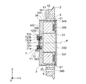
- Embodiment 5. 23 is a sectional view showing a wheel device according to Embodiment 5.
- FIG. 23 is a diagram corresponding to FIG. 2 in the first embodiment.
- the main body electric motor 33 has a stator 332 and an annular rotor 331 surrounding the outer circumference of the stator 332 . Therefore, the main body electric motor 33 is an outer rotor type electric motor.
- the respective axes of the rotor 331 and stator 332 are aligned with the axis of the main body 3 .
- the stator 332 is fixed to the fixed frame 31.
- the rotor 331 is attached to the stationary frame 31 via bearings 305 .
- a rotating frame 34 is fixed to the rotor 331 .
- Rotating frame 34 is attached to stator 332 via bearing 306 fitted in through hole 343 . As a result, the rotating frame 34 can rotate integrally with the rotor 331 about the axis of the main body 3 with respect to the stator 332 and the fixed frame 31 .
- the damping structure 7 is arranged outside the rotating frame 34 in the width direction of the vehicle body, that is, on the negative side of the rotating frame 34 in the Y-axis direction. Also, the damping structure 7 is supported by the stator 332 through the through hole 343 of the rotating frame 34 .
- the damping structure 7 has a weight 71 and a transmission mechanism 72 .
- the weight 71 is attached to the rotating frame 34 via the transmission mechanism 72 .
- the transmission mechanism 72 transmits the torque of the main body electric motor 33 to the weight 71 so that the rotation speed of the weight 71 becomes twice the rotation speed of the rotor 331 .
- the configuration of the transmission mechanism 72 is the same as that of the planetary gear mechanism according to the second embodiment. That is, the transmission mechanism 72 has a sun gear 721 , an internal gear 722 and a plurality of planetary gears 723 .
- Each of the sun gear 721 and the internal gear 722 is arranged coaxially with the axis of the main body 3 .
- Sun gear 721 is fixed to stator 332 .
- the internal gear 722 is an annular gear surrounding the sun gear 721 .
- Each planetary gear 723 is arranged between the sun gear 721 and the internal gear 722 . Each planetary gear 723 meshes with the sun gear 721 and the internal gear 722 respectively. Each planetary gear 723 is attached to the rotating frame 34 . The internal gear 722 is supported by each planetary gear 723 . Each planetary gear 723 revolves around the sun gear 721 around the axis of the main body 3 by rotating the rotating frame 34 integrally with the rotor 331 . Therefore, the revolution speed of each planetary gear 723 with respect to the sun gear 721 matches the rotational speed of the rotor 331 .
- the internal gear 722 rotates about the axis of the main body 3 with respect to the sun gear 721 while synchronizing with the revolution speed of each planetary gear 723 with respect to the sun gear 721 . Therefore, the transmission mechanism 72 according to the present embodiment is a solar-type planetary gear mechanism that receives the revolving force of each planetary gear 723 and outputs the rotational force of the internal gear 722 .
- Each planetary gear 723 has a gear shaft 723a, a first gear portion 723b, and a second gear portion 723c.
- the axis of the gear shaft 723 a coincides with the axis of the planetary gear 723 .
- the gear shaft 723 a is arranged parallel to the axis of the main body 3 . Further, the gear shaft 723a is rotatably attached to the rotating plate portion 342 of the rotating frame 34. As shown in FIG.
- the first gear portion 723b and the second gear portion 723c are fixed to the gear shaft 723a. Thereby, the first gear portion 723b is coaxially fixed to the second gear portion 723c.
- the gear shaft 723a, the first gear portion 723b, and the second gear portion 723c rotate together around the axis of the planetary gear 723. As shown in FIG.
- the first gear portion 723b and the second gear portion 723c are adjacent to each other in the axial direction of the gear shaft 723a.
- the first gear portion 723b meshes with the internal gear 722.
- the second gear portion 723c meshes with the sun gear 721. As shown in FIG.
- the number of teeth of the first gear portion 723b and the number of teeth of the second gear portion 723c are different from each other. In this embodiment, the number of teeth of the first gear portion 723b is greater than the number of teeth of the second gear portion 723c.
- the second gear portion 723c is positioned closer to the rotating frame 34 than the first gear portion 723b, that is, is positioned on the plus side in the Y-axis direction of the first gear portion 723b.
- the second gear portion 723c may be positioned farther from the rotating frame 34 than the first gear portion 723b, that is, on the negative side in the Y-axis direction of the first gear portion 723b.
- the speed transmission ratio i of the transmission mechanism 72 which is a solar-type planetary gear mechanism, is the number of teeth z1 of the sun gear 721, the number of teeth z2 of the internal gear 722, the number of teeth z3 of the first gear portion 723b, and the second gear portion. It is represented by the following equation (6) using the number of teeth z4 of 723c.
- each of the sun gear 721, the internal gear 722, the first gear portion 723b, and the second gear portion 723c is rotated so that the rotation speed of the internal gear 722 is double the rotation speed of the rotor 331.
- number of teeth is determined. That is, in the transmission mechanism 72, the sun gear 721, the internal gear 722, the first gear portion 723b, and the second gear are arranged so that the speed transmission ratio i of the rotational speed of the internal gear 722 to the rotational speed of the rotor 331 is 2.
- the number of teeth for each of the portions 723c is determined. Accordingly, when the rotor 331 rotates once, the internal gear 722 rotates twice in the same direction as the rotor 331 rotates.
- the weight 71 is fixed to the internal gear 722. Thereby, the weight 71 rotates integrally with the internal gear 722 . Therefore, the centerline of rotation of the weight 71 coincides with the axis of the main body 3 . Further, the position of the center of gravity 71 a of the weight 71 is set at a position away from the rotation center line of the weight 71 in a direction orthogonal to the rotation center line of the weight 71 . In the present embodiment, the position of the center of gravity 71a of weight 71 is set at a position away from the center line of rotation of weight 71 in the direction along the second imaginary straight line. The center of gravity 71 a of the weight 71 moves on a circle around the rotation center line of the weight 71 as the weight 71 rotates.
- the center of gravity 71a of the weight 71 is positioned on the negative side of the rotation center line of the weight 71 in the Z-axis direction in a state where the direction along the second imaginary straight line coincides with the Z-axis direction. are arranged so that Therefore, when the direction along the second imaginary straight line in the wheel device 1 coincides with the vertical direction, the position of the center of gravity 71 a of the weight 71 is positioned below the rotation center line of the weight 71 .
- Other configurations in the fifth embodiment are similar to those in the first embodiment.
- the main body electric motor 33 is an outer rotor type electric motor
- the transmission mechanism 72 is a solar type planetary gear mechanism. Therefore, the number of movable parts in the wheel device 1 can be reduced. As a result, it is possible to more reliably suppress the occurrence of failures in the wheel device 1 and to further improve the reliability of the wheel device 1 .
- Embodiment 6. 24 is a sectional view showing a wheel device according to Embodiment 6.
- FIG. 24 is a diagram corresponding to FIG. 2 in the first embodiment.
- the damping structure 7 is provided on a rotating frame 34 that rotates integrally with the rotor 331 .
- the damping structure 7 is arranged outside the rotating frame 34 in the width direction of the vehicle body, that is, on the minus side of the rotating frame 34 in the Y-axis direction.
- the damping structure 7 has a weight 71 and a damping electric motor 73 . In this embodiment, the damping structure 7 does not have a transmission mechanism.
- the damping electric motor 73 is an electric motor different from the main body electric motor 33 .
- the axis of the damping electric motor 73 coincides with the axis of the main body 3 .
- the damping electric motor 73 generates torque for rotating the weight 71 .
- the damping electric motor 73 has a weight driving portion 731 and a weight driving shaft 732 .
- the weight driving section 731 is fixed to the rotating frame 34 . As a result, the weight driving portion 731 rotates integrally with the rotating frame 34 around the axis of the main body 3 .
- the weight drive shaft 732 is rotatably provided in the weight drive section 731 . Also, the axis of the weight drive shaft 732 coincides with the axis of the main body 3 . The weight driving shaft 732 rotates around the axis of the main body 3 with respect to the weight driving portion 731 by power supply to the weight driving portion 731 .
- the main body electric motor 33 and the damping electric motor 73 are each controlled by a control device (not shown).
- the control device controls each of the main body electric motor 33 and the damping electric motor 73 so that the rotation speed of the weight drive shaft 732 with respect to the weight drive unit 731 and the rotation speed of the rotor 331 with respect to the stator 332 are the same.
- the control device also controls the main body electric motor 33 and the damping electric motor 73 so that the rotation direction of the weight drive shaft 732 and the rotation direction of the rotor 331 are the same.
- the weight 71 is fixed to the weight drive shaft 732 . As a result, the weight 71 rotates integrally with the weight drive shaft 732 around the axis of the main body 3 .
- the centerline of rotation of the weight 71 coincides with the axis of the main body 3 .
- the number of rotations of the weight 71 is the same as the number of rotations of the weight drive shaft 732 .
- the weight 71 rotates in the same direction as the rotational direction of the rotating frame 34 at twice the rotational speed of the rotating frame 34 .
- the configuration of the weight 71 is the same as the configuration of the weight 71 in the first embodiment. Therefore, the position of the center of gravity 71 a of the weight 71 is set at a position away from the rotation center line of the weight 71 in a direction orthogonal to the rotation center line of the weight 71 . In the present embodiment, the position of the center of gravity 71a of weight 71 is set at a position away from the center line of rotation of weight 71 in the direction along the second imaginary straight line. The center of gravity 71 a of the weight 71 moves on a circle around the rotation center line of the weight 71 as the weight 71 rotates.
- the center of gravity 71a of the weight 71 is positioned on the negative side of the rotation center line of the weight 71 in the Z-axis direction in a state where the direction along the second imaginary straight line coincides with the Z-axis direction. are arranged so that Therefore, when the direction along the second imaginary straight line in the wheel device 1 coincides with the vertical direction, the position of the center of gravity 71 a of the weight 71 is positioned below the rotation center line of the weight 71 .
- Other configurations in the sixth embodiment are similar to those in the third embodiment.
- a damping electric motor 73 that generates torque for rotating the weight 71 is provided on the rotating frame 34 . Therefore, the transmission mechanism can be eliminated, and the configuration of the wheel device 1 can be simplified. As a result, occurrence of failure of the wheel device 1 can be more reliably suppressed, and reliability of the wheel device 1 can be improved.
- the damping structure 7 is provided on the rotating frame 34 .
- the damping structure 7 may be provided on the main shaft 32 that rotates integrally with the rotor 331 .
- the weight driving portion 731 of the damping electric motor 73 is fixed to the main shaft 32 .
- the damping structure 7 may be provided at the first end 321 of the main shaft 32 or at the second end 322 of the main shaft 32 .
- the main shaft 32 is arranged to pass through the rotating plate portion 342 of the rotating frame 34 .
- Embodiment 7. 25 is a sectional view showing a wheel device according to Embodiment 7.
- FIG. 25 is a diagram corresponding to FIG. 2 in the first embodiment.
- the main body electric motor 33 is an outer rotor type electric motor as in the fifth embodiment.
- the damping structure 7 is arranged outside the rotating frame 34 in the width direction of the vehicle body, that is, on the negative side of the rotating frame 34 in the Y-axis direction. Also, the damping structure 7 is supported by the stator 332 through the through hole 343 of the rotating frame 34 .
- the configuration of the damping structure 7 is the same as that of the damping structure 7 in the sixth embodiment.
- the stator 332 is provided with a damping electric motor 73 that generates torque for rotating the weight 71 .
- the axis of the damping electric motor 73 coincides with the axis of the main body 3 .
- a weight driving portion 731 of the damping electric motor 73 is fixed to the stator 332 through the through hole 343 of the rotating frame 34 .
- the weight driving shaft 732 of the vibration damping electric motor 73 rotates about the axis of the main body 3 with respect to the weight driving portion 731 by power supply to the weight driving portion 731 .
- the main body electric motor 33 and the damping electric motor 73 are each controlled by a control device (not shown).
- the control device controls each of the main body electric motor 33 and the damping electric motor 73 so that the rotation speed of the weight drive shaft 732 with respect to the weight drive unit 731 is twice the rotation speed of the rotor 331 with respect to the stator 332 .
- the control device also controls the main body electric motor 33 and the damping electric motor 73 so that the rotation direction of the weight drive shaft 732 and the rotation direction of the rotor 331 are the same. As a result, the weight drive shaft 732 rotates in the same direction as the rotational direction of the rotating frame 34 at twice the rotating speed of the rotating frame 34 .
- the weight 71 is fixed to the weight drive shaft 732 . As a result, the weight 71 rotates integrally with the weight drive shaft 732 around the axis of the main body 3 . Therefore, the weight 71 rotates in the same direction as the rotational direction of the rotating frame 34 at twice the rotational speed of the rotating frame 34 .
- the configuration of the weight 71 is the same as the configuration of the weight 71 in the sixth embodiment. Therefore, the position of the center of gravity 71 a of the weight 71 is set at a position away from the rotation center line of the weight 71 in a direction orthogonal to the rotation center line of the weight 71 . In the present embodiment, the position of the center of gravity 71a of weight 71 is set at a position away from the center line of rotation of weight 71 in the direction along the second imaginary straight line. The center of gravity 71 a of the weight 71 moves on a circle around the rotation center line of the weight 71 as the weight 71 rotates.
- the center of gravity 71a of the weight 71 is positioned on the negative side of the rotation center line of the weight 71 in the Z-axis direction in a state where the direction along the second imaginary straight line coincides with the Z-axis direction. are arranged so that Therefore, when the direction along the second imaginary straight line in the wheel device 1 coincides with the vertical direction, the position of the center of gravity 71 a of the weight 71 is positioned below the rotation center line of the weight 71 .
- Other configurations in the seventh embodiment are similar to those in the fifth embodiment.
- the stator 332 is provided with the damping electric motor 73 that generates torque for rotating the weight 71 . Therefore, the transmission mechanism can be eliminated, and the configuration of the wheel device 1 can be simplified. As a result, occurrence of failure of the wheel device 1 can be more reliably suppressed, and reliability of the wheel device 1 can be improved.
- the damping structure 7 is provided on the stator 332 in the seventh embodiment.
- the damping structure 7 may be provided on the fixed frame 31 .
- the damping structure 7 is arranged on the inner side in the width direction of the vehicle body than the fixed frame 31 . Further, in this case, the weight driving portion 731 of the damping electric motor 73 is fixed to the fixed frame 31 .
- the weight 71 whose position of the center of gravity 71a is adjustable is applied to the weight 71 of the damping structure 7 in the first embodiment.
- the weight 71 of Embodiment 4 whose position of the center of gravity 71a is adjustable may be applied to the weight 71 of the damping structure 7 in Embodiments 2, 3, 6 and 7.
- the center line of rotation of the weight 71 coincides with the axis of the main body 3 .
- the rotation centerline of the weight 71 may be shifted from the axis of the main body 3 . Even in this way, at least part of the excitation force due to whirling of the intermediate member 4 can be canceled by the centrifugal force of the weight 71, and vibration of the entire wheel device 1 can be suppressed.
- the second virtual straight line is orthogonal to the first virtual straight line.
- the second imaginary straight line does not have to be orthogonal to the first imaginary straight line as long as it is a straight line that is orthogonal to the axis of the intermediate member 4 and different from the first imaginary straight line.
- the tire 2 is made of metal such as iron.
- the tire 2 may be made of an elastic material such as rubber. If the tire 2 is made entirely of metal, the wheel assembly 1 can be intentionally energized, for example for detecting vehicles on rails.
- the wheel device 1 is applied to a railway vehicle.
- the wheel device 1 can be applied to various vehicles or moving devices such as automobiles, motorcycles, and elevators.
Landscapes
- Engineering & Computer Science (AREA)
- Mechanical Engineering (AREA)
- Tires In General (AREA)
- Vibration Prevention Devices (AREA)
Abstract
Description
実施の形態1.
図1は、実施の形態1による車輪装置を示す正面図である。また、図2は、図1のII-II線に沿った断面図である。さらに、図3は、図1のIII-III線に沿った断面図である。図において、車輪装置1は、タイヤ2と、本体3と、中間部材4と、第1連結構造部5と、第2連結構造部6と、制振構造部7とを有している。本実施の形態では、鉄道車両の車体に設けられる鉄道車両用車輪装置が車輪装置1として用いられている。
図19は、実施の形態2による車輪装置を示す断面図である。なお、図19は、実施の形態1における図2に対応する図である。主軸32の第2端部322には、回転フレーム34の回転板部342が軸受け303を介して回転可能に取り付けられている。主軸32は、固定フレーム31よりもY軸方向のプラス側へ延びている。これにより、主軸32の第1端部321は、固定フレーム31よりも車体の幅方向内側に位置している。
図20は、実施の形態3による車輪装置を示す断面図である。なお、図20は、実施の形態1における図2に対応する図である。主軸32の第2端部322には、回転フレーム34の回転板部342が固定されている。これにより、回転フレーム34は、本体3の軸線を中心として主軸32及びロータ331と一体に回転する。従って、回転フレーム34は、本体電動機33のトルクによって、主軸32及びロータ331のそれぞれの回転数と同じ回転数で回転する。
図21は、実施の形態4による車輪装置を示す正面図である。また、図22は、図21のXXII-XXII線に沿った断面図である。なお、図21は、実施の形態1における図1に対応する図である。図22は、実施の形態1における図2に対応する図である。おもり71は、主軸32の第2端部322に固定されている。おもり71は、固定座711と、おもり本体712とを有している。
図23は、実施の形態5による車輪装置を示す断面図である。なお、図23は、実施の形態1における図2に対応する図である。本体電動機33は、ステータ332と、ステータ332の外周を囲む環状のロータ331とを有している。従って、本体電動機33は、アウタロータ型の電動機となっている。ロータ331及びステータ332のそれぞれの軸線は、本体3の軸線と一致している。
図24は、実施の形態6による車輪装置を示す断面図である。なお、図24は、実施の形態1における図2に対応する図である。制振構造部7は、ロータ331と一体に回転する回転フレーム34に設けられている。また、制振構造部7は、車体の幅方向において回転フレーム34よりも外側、即ち回転フレーム34よりもY軸方向のマイナス側に配置されている。制振構造部7は、おもり71と、制振用電動機73とを有している。本実施の形態では、制振構造部7が変速機構を有していない。
図25は、実施の形態7による車輪装置を示す断面図である。なお、図25は、実施の形態1における図2に対応する図である。本体電動機33は、実施の形態5と同様に、アウタロータ型の電動機となっている。制振構造部7は、車体の幅方向において回転フレーム34よりも外側、即ち回転フレーム34よりもY軸方向のマイナス側に配置されている。また、制振構造部7は、回転フレーム34の貫通穴343を通してステータ332に支持されている。
Claims (8)
- 回転可能な本体回転部を有する本体、
前記本体回転部を囲む環状の中間部材、
前記中間部材を囲む環状のタイヤ、
前記中間部材の軸線に直交する第1仮想直線に沿って前記中間部材が前記タイヤに対して移動可能になるように前記中間部材と前記タイヤとを互いに連結する第1弾性体、
前記中間部材の軸線に直交しかつ前記第1仮想直線に交差する第2仮想直線に沿って前記中間部材が前記本体に対して移動可能になるように前記中間部材と前記本体回転部とを互いに連結する第2弾性体、及び
前記本体に設けられている制振構造部
を備え、
前記制振構造部は、前記本体回転部の回転数に比べて2倍の回転数で前記本体回転部の回転方向と同じ方向へ回転するおもりを有しており、
前記第2仮想直線に沿った方向が鉛直方向と一致するときに、前記おもりの重心の位置が前記おもりの回転中心線よりも下方の位置になる車輪装置。 - 前記おもりは、前記おもりの回転中心線から前記おもりの重心までの距離を調整可能になっている請求項1に記載の車輪装置。
- 前記おもりの回転中心線から前記おもりの重心までの距離と前記おもりの質量との積は、前記タイヤが回転するときの鉛直方向における前記中間部材の変位と前記中間部材の質量との積の1/4倍と一致している請求項1又は請求項2に記載の車輪装置。
- 前記本体は、前記本体回転部を回転させるトルクを発生する本体電動機を有している請求項1~請求項3のいずれか一項に記載の車輪装置。
- 前記本体電動機は、ステータと、前記ステータに対して回転するロータとを有しており、
前記おもりは、前記ロータと一体に回転するようになっており、
前記本体は、前記本体回転部の回転数が前記ロータの回転数の1/2倍になるように前記本体電動機のトルクを前記本体回転部に伝達する変速機構を有している請求項4に記載の車輪装置。 - 前記本体電動機は、ステータと、前記ステータに対して回転するロータとを有しており、
前記本体回転部は、前記ロータと一体に回転するようになっており、
前記制振構造部は、前記おもりの回転数が前記ロータの回転数の2倍になるように前記本体電動機のトルクを前記おもりに伝達する変速機構を有している請求項4に記載の車輪装置。 - 前記変速機構は、太陽歯車と、前記太陽歯車を囲む環状の内歯歯車と、前記太陽歯車と前記内歯歯車との間に配置された遊星歯車とを有しており、
前記遊星歯車は、前記内歯歯車に噛み合う第1歯車部と、前記太陽歯車に噛み合う第2歯車部とを有しており、
前記第1歯車部は、前記第2歯車部に同軸に固定されており、
前記第1歯車部の歯数は、前記第2歯車部の歯数と異なっている請求項5又は請求項6に記載の車輪装置。 - 前記制振構造部は、前記おもりを回転させるトルクを発生する制振用電動機を有している請求項1~請求項4のいずれか一項に記載の車輪装置。
Priority Applications (4)
| Application Number | Priority Date | Filing Date | Title |
|---|---|---|---|
| CN202180092260.4A CN116829370A (zh) | 2021-02-02 | 2021-02-02 | 车轮装置 |
| DE112021006986.1T DE112021006986T5 (de) | 2021-02-02 | 2021-02-02 | Radeinrichtung |
| JP2022579176A JP7383181B2 (ja) | 2021-02-02 | 2021-02-02 | 車輪装置 |
| PCT/JP2021/003710 WO2022168154A1 (ja) | 2021-02-02 | 2021-02-02 | 車輪装置 |
Applications Claiming Priority (1)
| Application Number | Priority Date | Filing Date | Title |
|---|---|---|---|
| PCT/JP2021/003710 WO2022168154A1 (ja) | 2021-02-02 | 2021-02-02 | 車輪装置 |
Publications (1)
| Publication Number | Publication Date |
|---|---|
| WO2022168154A1 true WO2022168154A1 (ja) | 2022-08-11 |
Family
ID=82741231
Family Applications (1)
| Application Number | Title | Priority Date | Filing Date |
|---|---|---|---|
| PCT/JP2021/003710 WO2022168154A1 (ja) | 2021-02-02 | 2021-02-02 | 車輪装置 |
Country Status (4)
| Country | Link |
|---|---|
| JP (1) | JP7383181B2 (ja) |
| CN (1) | CN116829370A (ja) |
| DE (1) | DE112021006986T5 (ja) |
| WO (1) | WO2022168154A1 (ja) |
Citations (5)
| Publication number | Priority date | Publication date | Assignee | Title |
|---|---|---|---|---|
| JPH0694079A (ja) * | 1992-09-16 | 1994-04-05 | Honda Motor Co Ltd | エンジンの2次振動防振支持装置 |
| US20040000022A1 (en) * | 2002-06-27 | 2004-01-01 | Royal Appliance Mfg. Co | Resiliently-coupled drive wheel assembly for self-propelled vacuum cleaner |
| DE102016201694A1 (de) * | 2016-02-04 | 2017-08-10 | Schaeffler Technologies AG & Co. KG | Drehmomentenübertragungsanordnung für einen elektromechanischen Radnabenantrieb |
| CN108340733A (zh) * | 2018-04-24 | 2018-07-31 | 吉林大学 | 一种内置悬架车轮 |
| WO2020213154A1 (ja) * | 2019-04-19 | 2020-10-22 | 三菱電機株式会社 | 車輪装置 |
Family Cites Families (1)
| Publication number | Priority date | Publication date | Assignee | Title |
|---|---|---|---|---|
| WO2017168547A1 (ja) | 2016-03-29 | 2017-10-05 | 三菱電機株式会社 | 独立車輪駆動装置および車両 |
-
2021
- 2021-02-02 JP JP2022579176A patent/JP7383181B2/ja active Active
- 2021-02-02 CN CN202180092260.4A patent/CN116829370A/zh active Pending
- 2021-02-02 WO PCT/JP2021/003710 patent/WO2022168154A1/ja active Application Filing
- 2021-02-02 DE DE112021006986.1T patent/DE112021006986T5/de active Pending
Patent Citations (5)
| Publication number | Priority date | Publication date | Assignee | Title |
|---|---|---|---|---|
| JPH0694079A (ja) * | 1992-09-16 | 1994-04-05 | Honda Motor Co Ltd | エンジンの2次振動防振支持装置 |
| US20040000022A1 (en) * | 2002-06-27 | 2004-01-01 | Royal Appliance Mfg. Co | Resiliently-coupled drive wheel assembly for self-propelled vacuum cleaner |
| DE102016201694A1 (de) * | 2016-02-04 | 2017-08-10 | Schaeffler Technologies AG & Co. KG | Drehmomentenübertragungsanordnung für einen elektromechanischen Radnabenantrieb |
| CN108340733A (zh) * | 2018-04-24 | 2018-07-31 | 吉林大学 | 一种内置悬架车轮 |
| WO2020213154A1 (ja) * | 2019-04-19 | 2020-10-22 | 三菱電機株式会社 | 車輪装置 |
Also Published As
| Publication number | Publication date |
|---|---|
| DE112021006986T5 (de) | 2023-12-28 |
| CN116829370A (zh) | 2023-09-29 |
| JP7383181B2 (ja) | 2023-11-17 |
| JPWO2022168154A1 (ja) | 2022-08-11 |
Similar Documents
| Publication | Publication Date | Title |
|---|---|---|
| JP4799199B2 (ja) | インホイールモータ駆動装置 | |
| EP1979186B1 (en) | Wheel rotating device for in-wheel motor vehicle | |
| US7717203B2 (en) | Wheel rotating apparatus and in-wheel motor vehicle | |
| WO2015041038A1 (ja) | インホイールモータ駆動装置 | |
| CN100436860C (zh) | 具有旋转飞轮和行星齿轮系的防振装置 | |
| JP2013029195A (ja) | モータ駆動力伝達装置 | |
| US8562475B2 (en) | Eccentric rocking type reduction gear | |
| JP2020104696A (ja) | 転舵装置、および、それを備えた車両用車輪配設モジュール | |
| WO2005033544A2 (en) | Harmonic force generator for an active vibration control system | |
| CN112710459B (zh) | 航空发动机转子飞行状态模拟实验平台 | |
| US9938004B2 (en) | Bearing apparatus for power transmissions | |
| WO2013031623A1 (ja) | 車両用懸架装置 | |
| JP2019043177A (ja) | 車両用インホイールモータ駆動装置 | |
| CN105207520A (zh) | 一种旋转型行波超声电机及其定子与转子预紧方法 | |
| WO2022168154A1 (ja) | 車輪装置 | |
| US9765853B2 (en) | Power transmissions having pericyclic motion converters | |
| JP2012002264A (ja) | 回転直動変換機構 | |
| CN209812366U (zh) | 一种二轴关节装置 | |
| US20150097072A1 (en) | Active vibration control actuator | |
| CN210791046U (zh) | 一种基于带传动的中空旋转平台 | |
| JP7086508B2 (ja) | 車輪装置 | |
| CN107975564B (zh) | 动态不平衡力发生器以及包括这种发生器的致动器 | |
| JP5221486B2 (ja) | 摩擦式駆動装置 | |
| JP6598663B2 (ja) | パワーステアリング装置およびパワーステアリング装置の製造方法 | |
| CN109281992A (zh) | 用于在两个同轴齿轮之间分配扭矩的传动装置 |
Legal Events
| Date | Code | Title | Description |
|---|---|---|---|
| 121 | Ep: the epo has been informed by wipo that ep was designated in this application |
Ref document number: 21924551 Country of ref document: EP Kind code of ref document: A1 |
|
| ENP | Entry into the national phase |
Ref document number: 2022579176 Country of ref document: JP Kind code of ref document: A |
|
| WWE | Wipo information: entry into national phase |
Ref document number: 202180092260.4 Country of ref document: CN |
|
| WWE | Wipo information: entry into national phase |
Ref document number: 112021006986 Country of ref document: DE |
|
| 122 | Ep: pct application non-entry in european phase |
Ref document number: 21924551 Country of ref document: EP Kind code of ref document: A1 |