WO2022163672A1 - 画像表示装置 - Google Patents
画像表示装置 Download PDFInfo
- Publication number
- WO2022163672A1 WO2022163672A1 PCT/JP2022/002757 JP2022002757W WO2022163672A1 WO 2022163672 A1 WO2022163672 A1 WO 2022163672A1 JP 2022002757 W JP2022002757 W JP 2022002757W WO 2022163672 A1 WO2022163672 A1 WO 2022163672A1
- Authority
- WO
- WIPO (PCT)
- Prior art keywords
- light guide
- unit
- display image
- display
- image light
- Prior art date
Links
- 230000007246 mechanism Effects 0.000 claims abstract description 72
- 125000006850 spacer group Chemical group 0.000 claims description 21
- 238000010586 diagram Methods 0.000 description 15
- 230000006870 function Effects 0.000 description 13
- 230000002093 peripheral effect Effects 0.000 description 9
- 230000003287 optical effect Effects 0.000 description 8
- 238000012986 modification Methods 0.000 description 6
- 230000004048 modification Effects 0.000 description 6
- 210000001747 pupil Anatomy 0.000 description 6
- 238000012360 testing method Methods 0.000 description 5
- 239000002131 composite material Substances 0.000 description 4
- 230000000644 propagated effect Effects 0.000 description 4
- 230000009471 action Effects 0.000 description 3
- 238000000034 method Methods 0.000 description 3
- 239000000853 adhesive Substances 0.000 description 2
- 230000001070 adhesive effect Effects 0.000 description 2
- 238000013459 approach Methods 0.000 description 2
- 230000008859 change Effects 0.000 description 2
- 238000012937 correction Methods 0.000 description 2
- 239000000835 fiber Substances 0.000 description 2
- 239000004973 liquid crystal related substance Substances 0.000 description 2
- 238000012545 processing Methods 0.000 description 2
- 238000004026 adhesive bonding Methods 0.000 description 1
- 230000000593 degrading effect Effects 0.000 description 1
- 238000005401 electroluminescence Methods 0.000 description 1
- 238000003780 insertion Methods 0.000 description 1
- 230000037431 insertion Effects 0.000 description 1
- 238000009434 installation Methods 0.000 description 1
- 238000004519 manufacturing process Methods 0.000 description 1
- 239000000203 mixture Substances 0.000 description 1
- 239000004065 semiconductor Substances 0.000 description 1
Images


Classifications
-
- G—PHYSICS
- G02—OPTICS
- G02B—OPTICAL ELEMENTS, SYSTEMS OR APPARATUS
- G02B27/00—Optical systems or apparatus not provided for by any of the groups G02B1/00 - G02B26/00, G02B30/00
- G02B27/01—Head-up displays
- G02B27/017—Head mounted
- G02B27/0172—Head mounted characterised by optical features
-
- G—PHYSICS
- G02—OPTICS
- G02B—OPTICAL ELEMENTS, SYSTEMS OR APPARATUS
- G02B27/00—Optical systems or apparatus not provided for by any of the groups G02B1/00 - G02B26/00, G02B30/00
- G02B27/01—Head-up displays
-
- G—PHYSICS
- G02—OPTICS
- G02B—OPTICAL ELEMENTS, SYSTEMS OR APPARATUS
- G02B27/00—Optical systems or apparatus not provided for by any of the groups G02B1/00 - G02B26/00, G02B30/00
- G02B27/01—Head-up displays
- G02B27/017—Head mounted
- G02B27/0176—Head mounted characterised by mechanical features
-
- G—PHYSICS
- G02—OPTICS
- G02B—OPTICAL ELEMENTS, SYSTEMS OR APPARATUS
- G02B27/00—Optical systems or apparatus not provided for by any of the groups G02B1/00 - G02B26/00, G02B30/00
- G02B27/02—Viewing or reading apparatus
-
- H—ELECTRICITY
- H04—ELECTRIC COMMUNICATION TECHNIQUE
- H04N—PICTORIAL COMMUNICATION, e.g. TELEVISION
- H04N5/00—Details of television systems
- H04N5/64—Constructional details of receivers, e.g. cabinets or dust covers
-
- G—PHYSICS
- G02—OPTICS
- G02B—OPTICAL ELEMENTS, SYSTEMS OR APPARATUS
- G02B27/00—Optical systems or apparatus not provided for by any of the groups G02B1/00 - G02B26/00, G02B30/00
- G02B27/01—Head-up displays
- G02B27/017—Head mounted
- G02B2027/0178—Eyeglass type
Definitions
- the present invention relates to an image display device, and more particularly to an image display device used in front of one's eyes.
- a head-mounted image display device uses a plurality of display elements, and the images displayed on each display element are individually led to the observer's eyes, and synthesized into one. Techniques for allowing an observer to view an image are described.
- JP 2011-164545 A Japanese Patent Application Laid-Open No. 2001-264683 Japanese Patent Application Laid-Open No. 2014-41280
- One embodiment according to the technology of the present disclosure provides an image display device that allows observation of high-quality images.
- a plurality of display image light input devices for inputting display image light, and the display image light is individually input from the plurality of display image light input devices arranged in an overlapping manner, and the input display image light is input.
- An image display device comprising: a plurality of light guide plates that individually reflect and propagate to an output surface; and a first adjustment mechanism that adjusts the positional relationship of the plurality of light guide plates.
- the first adjustment mechanism includes a holding member that holds the plurality of light guide plates in an overlapping manner, and individually adjusts the positional relationship of the plurality of light guide plates with respect to the holding member.
- the holding member holds the light guide plate at a plurality of holding points set in the same plane, and the first adjustment mechanism individually adjusts the distance between the light guide plate and the holding member at each holding point.
- the image display device according to (3) wherein the arrangement relationship of the plurality of light guide plates with respect to the holding member is individually adjusted.
- the first adjustment mechanism includes a fastening member that fastens the light guide plate and the holding member at each holding point, and an urging member that urges the light guide plate and the holding member at each holding point in a direction to separate them from each other. and the image display device of (4).
- the first adjustment mechanism includes a fastening member that fastens the light guide plate and the holding member at each holding point, and a spacer member that is arranged between the light guide plate and the holding member at each holding point.
- the first adjustment mechanism includes a spacer member inserted between the plurality of light guide plates, and adjusts the insertion position and/or thickness of the spacer member to adjust the relative arrangement of the plurality of light guide plates.
- the processor receives an instruction to adjust a position where the display image light input device inputs the display image light to the light guide plate, and the display image light input device moves the light guide plate according to the received adjustment instruction.
- the image display device according to any one of (1) to (13), which adjusts the position for inputting the display image light with respect to the
- a plurality of display image light input devices for inputting display image light, and the display image light is individually input from the plurality of display image light input devices arranged in an overlapping manner, and the input display image light is input;
- An image display device comprising a plurality of light guide plates that propagate to an output surface while being individually reflected, and a plurality of third adjustment mechanisms that individually adjust the positional relationship between each light guide plate and a display image light input device.
- the processor receives an instruction to adjust a position where the display image light input device inputs the display image light to the light guide plate, and the display image light input device moves the light guide plate according to the received adjustment instruction.
- the image display device according to any one of (15) to (16), which adjusts the position for inputting the display image light with respect to the
- a plurality of display image light input devices for inputting display image light, and the display image light is individually input from the plurality of display image light input devices arranged in an overlapping manner, and the input display image light is input; a plurality of light guide plates that propagate to an output surface while being individually reflected; and a processor, wherein the processor receives and accepts an instruction for adjusting a position at which the display image light input device inputs the display image light to the light guide plate.
- the display image light input device adjusts a position where the display image light is input to the light guide plate according to the adjustment instruction.
- FIG. 2 is a front view showing a schematic overall configuration of an image display unit including an adjustment mechanism; The top view of the image display unit shown in FIG. 10-10 sectional view of FIG. 11-11 sectional view of FIG. 12-12 sectional view of FIG. Front view of the image display unit with the second unit removed Sectional drawing which shows the support structure of the 2nd unit in a 2nd unit attachment part FIG.
- FIG. 10 is a diagram showing another example of a configuration for adjusting the gap between the second frame screwing portion and the second unit mounting portion;
- 1 is a front view showing a schematic configuration of an image display unit;
- FIG. 1 is a front view showing a schematic configuration of an image display unit;
- FIG. 18-18 sectional view of FIG. 1 is a front view showing a schematic configuration of an image display unit;
- FIG. 24 is a top view showing a schematic configuration of the image display unit shown in FIG. 24; 27-27 sectional view of FIG.
- Conceptual diagram for electronically adjusting the synthesized state of observed images Block diagram showing the electrical configuration of the image display unit Block diagram of functions possessed by the display control unit
- Block diagram showing another example of
- FIG. 1 is a diagram showing an example of a head-mounted image display device.
- the figure shows an example of a so-called glasses-type head-mounted image display device 1 .
- the eyeglasses-type head-mounted image display device 1 is an image display device having a so-called eyeglass-like shape, and the lens portion of ordinary eyeglasses is configured as an image display unit.
- FIG. 1 shows an example in which one of the two lens portions (lens portion on the left eye side) is configured as an image display section.
- the image display unit 10 is incorporated in the lens portion on one side of the frame 2 that constitutes the spectacles.
- the image display unit 10 is an example of an image display device.
- FIG. 2 is a diagram showing a schematic configuration of an image display unit.
- the image display unit 10 of this embodiment is configured by combining a first unit 10A and a second unit 10B.
- the first unit 10A and the second unit 10B each have a function of displaying images individually. That is, the image display unit 10 of the present embodiment uses a combination of two units each having a function of individually displaying an image, and allows the observer to observe the combined image, thereby creating an image that can be observed by the observer. expand the range of
- FIG. 3 is a perspective view showing a schematic configuration of the first unit.
- FIG. 4 is a front view showing a schematic configuration of the first unit. It should be noted that the front here is the surface facing the observer's eyes when the observer observes the image.
- FIG. 5 is a top view showing a schematic configuration of the first unit.
- FIG. 6 is a side view showing a schematic configuration of the first unit. In each figure, the long side direction of the light guide plate is the X-axis direction, the short side direction is the Y-axis direction, and the thickness direction is the Z-axis direction.
- the X-axis direction is the horizontal direction (horizontal direction) when observing an image
- the Y-axis direction is the vertical direction (vertical direction) when observing an image
- the Z-axis direction is the depth direction (front-back direction) when observing an image.
- the first unit 10A has a first display image light input device 20A and a first light guide plate 30A.
- the first display image light input device 20A mainly has a first display element 21A and a first input optical system 22A.
- the first display element 21A is composed of, for example, a liquid crystal panel, an organic electro-luminescence (OEL) panel, or the like. Light emitted from each point of the first display element 21A constitutes display image light.
- OEL organic electro-luminescence
- the first input optical system 22A is a so-called collimating lens, and converts the light emitted from each point of the first display element 21A into a parallel beam.
- the first display image light input device 20A makes the display image light incident on the first light guide plate 30A at a predetermined incident angle.
- the first light guide plate 30A internally reflects the display image light input from the first display image light input device 20A multiple times and guides it to the observer's pupil. As shown in FIG. 3, the first light guide plate 30A has a rectangular parallel plate shape as a whole. The first light guide plate 30A is translucent and is configured to enable recognition of the surrounding real space through the first light guide plate 30A.
- the first light guide plate 30A has a first input section 31A to which the display image light from the first display image light input device 20A is input, and a first output section 32A to output the display image light toward the pupil. .
- the first input section 31A is provided at one end in the horizontal direction of the first light guide plate 30A.
- the surface on the front side of the first light guide plate 30A (the surface facing the observer's eyes) is configured as a first input surface 33A for display image light.
- the first input section 31A is provided with a mirror 34A.
- the mirror 34A reflects the display image light input to the first input surface 33A in a predetermined direction.
- the display image light reflected by the mirror 34A travels along the horizontal direction (X-axis direction) while being reflected inside the first light guide plate 30A, and is output from the first output section 32A. .
- the surface on the front side of the first light guide plate 30A is configured as a first output surface 35A for display image light.
- the first output section 32A is provided with a plurality of half mirrors 36A, 36A, .
- the half mirrors 36A, 36A, . . . are arranged at predetermined intervals.
- the display image light propagated while being reflected inside the first light guide plate 30A is reflected in a predetermined direction by the plurality of half mirrors 36A, 36A, . . . and output from the first output surface 35A.
- the observer observes an image represented by the display image light.
- FIG. 7 is a perspective view showing a schematic configuration of the second unit.
- the basic configuration is the same as the first unit 10A.
- the second display image light input device 20B mainly has a second display element 21B and a second input optical system 22B.
- the second display element 21B is composed of, for example, a liquid crystal panel, an organic EL panel, or the like. Light emitted from each point of the second display element 21B constitutes display image light.
- the second input optical system 22B is a so-called collimator lens, and converts the light emitted from each point of the second display element 21B into a parallel beam.
- the second display image light input device 20B makes the display image light incident on the second light guide plate 30B at a predetermined incident angle.
- the second light guide plate 30B internally reflects the display image light input from the second display image light input device 20B multiple times and guides it to the observer's pupil.
- the second light guide plate 30B has a rectangular parallel plate shape as a whole.
- the second light guide plate 30B has translucency, and is configured so that the surrounding real space can be recognized through the second light guide plate 30B.
- the second light guide plate 30B has a second input section 31B into which the display image light from the second display image light input device 20B is input, and a second output section 32B that outputs the display image light toward the pupil. .
- the second input section 31B is provided at one end in the horizontal direction of the second light guide plate 30B.
- the surface on the front side of the second light guide plate 30B is configured as a second input surface 33B for display image light.
- the second input section 31B is provided with a mirror 34B.
- the mirror 34B reflects the display image light input to the second input surface 33B in a predetermined direction.
- the display image light reflected by the mirror 34B travels along the horizontal direction (X-axis direction) while being reflected inside the second light guide plate 30B, and is output from the second output section 32B.
- the surface on the front side of the second light guide plate 30B is configured as a second output surface 35B for display image light.
- the second output section 32B is provided with a plurality of half mirrors 36B, 36B, .
- the half mirrors 36B, 36B, . . . are arranged at predetermined intervals.
- the display image light propagated while being reflected inside the second light guide plate 30B is reflected in a predetermined direction by the plurality of half mirrors 36B, 36B, . . . and output from the second output surface 35B.
- the observer observes an image represented by the display image light.
- first light guide plate 30A and the second light guide plate 30B have the same dimension in the vertical direction (Y-axis direction), but differ in dimension in the horizontal direction (X-axis direction).
- the second light guide plate 30B is set to have a smaller lateral dimension than the first light guide plate 30A. This is for aligning the positions of both ends when assembled.
- the image display unit 10 is configured by combining two units. Specifically, it is configured by arranging the first unit 10A and the second unit 10B so as to overlap each other in a predetermined arrangement relationship.
- This positional relationship is a positional relationship in which the images displayed by each unit are synthesized and observed as one image. More specifically, it is an arrangement relationship in which images displayed in each unit are joined together in the horizontal direction (X-axis direction) and observed as one image. This is a layout relationship for so-called panorama composition in the horizontal direction.
- the image displayed by each unit is It is set to the relationship that is synthesized and observed.
- the image display unit 10 of the present embodiment when one end of the light guide plate of each unit is aligned, the images displayed by each unit are combined and observed.
- the front side refers to the side closer to the observer's eyes in the depth direction (Z-axis direction).
- the end to be aligned is the end on the output side of the light guide plate of each unit.
- the units are stacked in parallel with each other with the heights of the light guide plates aligned.
- each unit must be set so that the display image light is input to the light guide plate at a predetermined incident angle.
- the incident angle of the display image light set in each unit is the angle at which the image displayed in each unit is combined and observed when two units are superimposed in a predetermined layout relationship.
- the image display unit 10 by arranging two units in a predetermined layout relationship, the images displayed by each unit are synthesized and viewed as one image. On the other hand, if the two units are not arranged in a predetermined positional relationship, seams appear in the observed image, significantly degrading the quality. However, it is difficult to accurately assemble the two units in a predetermined positional relationship. In addition, high component precision is required for accurate assembly. Therefore, the image display unit 10 of the present embodiment is provided with a mechanism (adjustment mechanism) for adjusting the positional relationship between the two units.
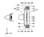
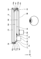
- FIG. 8 is a front view showing the overall schematic configuration of the image display unit including the adjustment mechanism.
- 9 is a top view of the image display unit shown in FIG. 8.
- FIG. 10 is a cross-sectional view taken along line 10-10 of FIG. 8.
- FIG. 11 is a cross-sectional view taken along line 11-11 of FIG. 8.
- FIG. 12 is a cross-sectional view taken along line 12-12 of FIG. 8.
- the first unit 10A is unitized by attaching the first display image light input device 20A and the first light guide plate 30A to the first frame 110.
- the first frame 110 is composed of a first frame main body 112 and a first display image light input device mounting portion 114 integrally provided with the first frame main body 112 .
- the first frame main body 112 is a holding portion for the first light guide plate 30A and has a rectangular frame shape.
- the first light guide plate 30A is held on the inner periphery of the first frame main body 112 .
- the first display image light input device mounting portion 114 is a mounting portion for the first display image light input device 20A.
- the first display image light input device 20A is attached to the first display image light input device attachment portion 114 so as to be positioned and attached at a predetermined position.
- the second unit 10B is unitized as one unit by attaching the second display image light input device 20B and the second light guide plate 30B to the second frame 120 .
- the second frame 120 is mainly composed of a second frame main body 122 and a second display image light input device mounting portion 124 integrally provided with the second frame main body 122 .
- the second frame main body 122 is a holding portion for the second light guide plate 30B and has a rectangular frame shape.
- the second light guide plate 30B is held on the inner periphery of the second frame main body 122 .
- the second display image light input device mounting portion 124 is a mounting portion for the second display image light input device 20B.
- the second display image light input device 20B is attached to the second display image light input device attachment portion 124 so as to be positioned and attached to the second light guide plate 30B at a predetermined position.
- the first unit 10A and the second unit 10B are each attached to the base frame 130 and integrated.
- Base frame 130 is an example of a holding member.
- the base frame 130 has a rectangular frame shape, as shown in FIG.
- the inner peripheral portion 132 of the base frame 130 functions as a holding portion for the first unit 10A.
- the first unit 10A is attached to the base frame 130 by fitting the first frame main body 112 into the inner peripheral portion 132 of the base frame 130 . Therefore, the inner peripheral portion 132 of the base frame 130 has a shape corresponding to the shape of the outer periphery of the first frame main body 112 .
- the first frame main body 112 fitted in the inner peripheral portion 132 is fixed to the base frame 130 by screwing the first unit fixing screws 150 at a plurality of locations (see FIGS. 9 and 11). Thereby, the first unit 10A and the base frame 130 are integrated.
- the second unit 10B is attached to the base frame 130 using the second unit tilt adjustment screw 140.
- the second unit tilt adjusting screw 140 is an example of a fastening member.
- the second frame main body 122 is provided with second frame screwing portions 126a, 126b, and 126c at three locations on the outer peripheral portion.
- the arrangement of the three second frame screwing portions 126a, 126b, 126c is as follows. That is, the second frame screwing portion 126a indicated by reference numeral 126a is provided at the center of the right side of the second frame main body 122 in FIG. A second frame screwing portion 126b indicated by reference numeral 126b is provided at the left end of the upper side of the second frame main body 122 in FIG. A second frame screwing portion 126c indicated by reference numeral 126c is provided at the left end of the lower side of the second frame main body 122 in FIG.
- Each of the second frame screwing portions 126a, 126b, 126c is provided with a hole 128 through which the second unit tilt adjusting screw 140 is passed.
- Each hole 128 has an inner diameter ⁇ 2 larger than the outer diameter ⁇ 1 of the second unit tilt adjusting screw 140 ( ⁇ 1 ⁇ 2). That is, each hole 128 has a relationship that creates a gap (so-called “play”) with the second unit tilt adjusting screw 140 when the second unit tilt adjusting screw 140 is passed through.
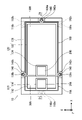
- FIG. 13 is a front view of the image display unit with the second unit removed.
- the base frame 130 is provided with second unit mounting portions 142a, 142b, and 142c at three locations on the front side surface.
- Each of the second unit mounting portions 142a, 142b, 142c is configured by a columnar projection and arranged on the same plane.
- the arrangement of the second unit mounting portions 142a, 142b, 142c is the same as the arrangement of the three second frame screwing portions 126a, 126b, 126c provided on the second frame main body 122. As shown in FIG.
- a screw hole 144 is provided in each of the second unit mounting portions 142a, 142b, 142c.
- a screw hole 144 is arranged in the center of the top of each second unit mounting portion 142a, 142b, 142c. Further, the screw hole 144 has a dimension corresponding to the second unit tilt adjusting screw 140 and is arranged along the depth direction (Z-axis direction).
- the screws 140 for adjusting the tilt of the second unit are passed through the holes 128 of the second frame screwing portions 126a, 126b, and 126c, and the screws of the second unit mounting portions 142a, 142b, and 142c of the base frame 130 are inserted.
- the second unit is attached to the base frame 130 by fitting the second unit tilt adjusting screw 140 into the hole 144 .
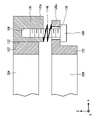
- FIG. 14 is a cross-sectional view showing the support structure of the second unit at the second unit mounting portion. This figure shows the support structure in the second unit mounting portion indicated by reference numeral 126a. The same is true for the support structure in other second unit mounting portions.
- the second unit 10B is attached to the base frame 130 with a second unit biasing spring 146 interposed therebetween.
- the second unit biasing spring 146 is composed of, for example, a coil spring.
- the second unit biasing spring 146 is arranged between the second unit mounting portion 142a and the second frame screwing portion 126a with the second unit tilt adjusting screw 140 passing through its inner peripheral portion.
- second unit biasing springs 146 are arranged between the other second frame screwing portions 126b and 126c and the second unit mounting portions 142b and 142c.
- the second unit urging spring 146 urges the second unit 10B away from the base frame 130 at the second frame screwing portions 126a, 126b, and 126c.
- the second unit biasing spring 146 is an example of a biasing member.
- the second unit 10B has the second unit mounting portions 142a, 142b, 142c interposed between the second frame screwing portions 126a, 126b, 126c and the second unit urging springs 146. , attached to the base frame 130 .
- the function of adjusting the inclination of the second unit 10B with respect to the base frame 130 is realized.
- the tilt is adjusted as follows.
- the second unit tilt adjusting screw 140 is loosened in each of the second frame screwing portions 126a, 126b, 126c, the second unit 10B is separated from the base frame 130 at the loosened portion.
- the second unit tilt adjusting screws 140 are tightened at the second frame screwing portions 126a, 126b, and 126c, the second unit 10B approaches the base frame 130 at the tightened locations.
- the tilt can be adjusted. For example, in FIG. 10, when the second unit tilt adjusting screw 140 of the second frame screwing portion 126a indicated by reference numeral 126a is turned, the entire second unit 10B tilts around the Y axis.
- the second unit 10B adjusts the inclination with respect to the base frame 130 by individually adjusting the tightening amounts of the second unit inclination adjusting screws 140 at the second frame screwing portions 126a, 126b, and 126c. can.
- the inclination relative to the first unit 10A attached to the base frame 130 can be adjusted.
- the inclination of the second light guide plate 30B can be adjusted with respect to the first light guide plate 30A.
- the structure that holds the inclination of the second unit 10B so as to be adjustable is an example of the first adjustment mechanism.
- each of the second unit mounting portions 142a, 142b, 142c provided on the base frame 130 is an example of a holding point.
- the first unit 10A and the second unit 10B are assembled. That is, the first display image light input device 20A and the first light guide plate 30A are assembled to the first frame 110 . Also, the second display image light input device 20B and the second light guide plate 30B are assembled to the second frame 120 .
- first unit 10A and the second unit 10B are assembled to the base frame 130.
- the first unit 10A is attached to the base frame.
- the first unit 10A is attached to the base frame 130 by fitting the first frame main body 112 to the inner peripheral portion of the base frame 130 and fixing it with the first unit fixing screws 150 .
- the second unit 10B is attached to the base frame.
- the second unit 10B is attached to the base frame 130 by screwing the second unit tilt adjusting screws 140 to the three second frame screwing portions 126a, 126b, and 126c.
- the second unit biasing spring 146 is interposed between each of the second frame screwing portions 126a, 126b, 126c and the base frame 130 for attachment.
- a case where two images are displayed correctly is a case where the images displayed from each unit are correctly joined and can be recognized as one image. That is, it is a case where the joints are displayed without being visible.
- Fixing is performed by, for example, using an adhesive to bond the second frame screwing portions 126a, 126b, 126c to the second unit mounting portions 142a, 142b, 142c.
- the image display unit 10 is incorporated into the lens portion of the spectacle-shaped frame 2 that constitutes the head-mounted image display device 1, and the head-mounted image display device 1 is completed.
- the image display unit 10 of the present embodiment when using two units to generate a synthesized image, the arrangement relationship between the two units can be adjusted. This allows post hoc correction even if the images from the two units do not stitch together correctly at the stage of assembly. Thereby, a high-quality image can be presented. In addition, required part accuracy and assembly accuracy can be reduced.
- the inclination of the second unit 10B is adjusted by individually adjusting the distances between the second frame screwing portions 126a, 126b, and 126c and the second unit mounting portions 142a, 142b, and 142c.
- the mechanism for adjusting the distance between the second frame screwing portions 126a, 126b, and 126c and the second unit mounting portions 142a, 142b, and 142c is not limited to the above embodiment. Various configurations can be employed.
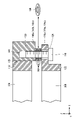
- FIG. 15 is a diagram showing another example of a configuration for adjusting the gap between the second frame screwing portion and the second unit mounting portion.
- the gap between the two is reduced.
- the spacer 148 has a disk-like shape, and the second unit tilt adjusting screw 140 is passed through the inner peripheral portion of the spacer 148 so that the second frame screwing portions 126a (126b, 126c) and the second unit mounting portions 142a (142b, 142b, 142c).
- Spacer 148 is an example of a spacer member.
- the interval is adjusted by adjusting the number of spacers 148 to be inserted.
- the spacer is not particularly limited, and a wedge-shaped spacer can also be used.
- the spacer is inserted at a predetermined position (the position of the second unit mounting portion), but it is also possible to insert the spacer at an arbitrary position to adjust the inclination. . Specifically, the position and/or the thickness of the spacer inserted between the second frame main body and the base frame are adjusted to adjust the inclination of the second unit with respect to the base frame. In this case, after adjusting the inclination, the second frame main body and the base frame are fixed by adhesion or the like.
- the inclination is directly adjusted between the first light guide plate and the second light guide plate without using a frame or the like. That is, the position and/or the thickness of the spacer inserted between the first light guide plate and the second light guide plate are adjusted to adjust the relative tilt between the two.
- the first light guide plate and the second light guide plate are fixed by adhesion or the like to be integrated.
- the first display image light input device and the second display image light input device are assembled to the integrated first light guide plate and second light guide plate to form an image display unit.
- the entire second unit is held with respect to the base frame so that the inclination thereof can be adjusted. good too.
- a configuration may be adopted in which only the display image light input device is held so that the tilt can be adjusted.
- the light guide plate and the display image light input device are independently attached to the base frame, and only the light guide plate is tiltably held.
- the display image light input device is held so that the tilt can be adjusted, for example, the light guide plate and the display image light input device are independently attached to the base frame, and only the display image light input device is tilt-adjustable. It is configured to hold as much as possible.
- the second unit is held at three points (three holding points), but it may be held at two or more points. When held at two points, it is held so that the tilt can be adjusted only in one direction.
- each unit is held by the base frame, and the second unit is held with respect to the base frame so that the inclination can be adjusted. It may be configured to be held in an adjustable manner.
- the first frame main body of the first unit is provided with the second unit mounting portion.
- the image display unit of the first embodiment is configured such that the tilt can be relatively adjusted between the two units.
- the image display unit of the present embodiment is further configured so that the two-dimensional position can be adjusted. That is, the configuration is such that the shift amount can be adjusted.
- FIG. 16 is a front view showing a schematic configuration of the image display unit.
- the image display unit 10 of the present embodiment includes a mechanism for adjusting the position of the second unit 10B in addition to the mechanism for adjusting the inclination of the second unit 10B. Since the mechanism for adjusting the inclination is the same as in the first embodiment, only the mechanism for adjusting the position will be described here. A mechanism for adjusting the position is another example of the first adjustment mechanism.
- the mechanism for adjusting the position includes a horizontal position adjusting mechanism 210 for adjusting the position in the horizontal direction (X-axis direction) and a vertical position adjusting mechanism 220 for adjusting the position in the vertical direction (Y-axis direction). and consists of
- the lateral position adjusting mechanism 210 is mainly composed of a pair of lateral biasing springs 212 and a pair of lateral position adjusting screws 214.
- a pair of lateral biasing springs 212 are attached to the base frame 130 via brackets 216 .
- the pair of laterally biasing springs 212 respectively abut on one side (the right side in FIG. 16) of the second frame main body 122 to laterally bias the second unit 10B.
- a pair of lateral position adjusting screws 214 are arranged to face a pair of lateral biasing springs 212 with the second unit 10B interposed therebetween.
- Each lateral position adjustment screw 214 is attached to the base frame 130 via a bracket 218 . Specifically, it is attached to a screw hole (not shown) provided in the bracket 218 .
- Each lateral position adjusting screw 214 attached to the bracket 218 has its tip abutted against a screw abutting portion 122A provided on the side surface on the other side (left side in FIG. 16) of the second frame main body 122 .
- the second unit 10B is sandwiched between the pair of lateral biasing springs 212 and the pair of lateral position adjusting screws 214 in the lateral direction.
- the vertical position adjusting mechanism 220 is mainly composed of a pair of vertical biasing springs 222 and a pair of vertical position adjusting screws 224.
- a pair of vertical biasing springs 222 are attached to the base frame 130 via brackets 226 .
- the pair of vertical direction biasing springs 222 respectively abut on the upper surface of the second frame body 122 and bias the second unit 10B in the vertical direction (downward).
- a pair of vertical position adjusting screws 224 are arranged to face a pair of vertical biasing springs 222 with the second unit 10B interposed therebetween.
- Each vertical position adjustment screw 224 is attached to the base frame 130 via a bracket 228 . Specifically, it is attached to a screw hole (not shown) provided in the bracket 228 .
- each vertical position adjusting screw 224 attached to the bracket 228 abuts against the lower surface of the second frame main body 122 .
- the second unit 10B is sandwiched between the pair of vertical biasing springs 222 and the pair of vertical position adjusting screws 224 in the vertical direction.
- the relative position between the first unit 10A and the second unit 10B can be adjusted by the lateral position adjusting mechanism 210 and the vertical position adjusting mechanism 220 configured as described above.
- the adjustment is performed in the horizontal direction (X-axis direction) and the vertical direction (Y-axis direction).
- Lateral adjustment is performed by the lateral position adjusting screw 214.
- the lateral position adjusting screw 214 When the lateral position adjusting screw 214 is turned, the lateral position adjusting screw 214 moves back and forth in the lateral direction. As a result, the second unit 10B is pushed by the lateral position adjusting screw 214 and moves laterally. That is, the position is adjusted in the lateral direction.
- Adjustment in the vertical direction is performed by the vertical position adjustment screw 224.
- the vertical position adjusting screw 224 moves back and forth in the vertical direction.
- the vertical position adjusting screw 224 pushes the second unit 10B to move in the vertical direction. That is, the position is adjusted in the vertical direction.
- the movable range of the second unit 10B is the range of the gap formed between the hole 128 and the second unit tilt adjusting screw 140 in each of the second frame screwing portions 126a, 126b, 126c. Therefore, a gap (clearance) necessary for movement is secured between the hole 128 and the second unit tilt adjusting screw 140 .
- the position can be adjusted in addition to adjusting the tilt. This allows a higher degree of adjustment.
- both the tilt adjusting function and the position adjusting function are provided, but it is also possible to provide only the position adjusting function.
- the entire second unit is held with respect to the base frame so that the inclination and the position thereof can be adjusted.
- the entire second unit is held with respect to the base frame so that the inclination and the position thereof can be adjusted.
- only the display image light input device may be held so as to be tiltable and positionally adjustable independently.
- each unit is held by the base frame, and the second unit is held with respect to the base frame so that the tilt and position of the second unit can be adjusted.
- a configuration may be adopted in which the two units are held so that the inclination and/or the position can be adjusted.
- the composite state of the observed image can also be adjusted by the positional relationship between the light guide plate and the display image light input device.
- FIG. 17 is a front view showing a schematic configuration of the image display unit.
- 18 is a cross-sectional view taken along line 18-18 of FIG. 17.
- the image display unit 10 of the present embodiment is provided with a tilt adjustment mechanism 300 for adjusting the tilt of the second display image light input device 20B.
- the tilt adjustment mechanism 300 is an example of a mechanism (second adjustment mechanism and third adjustment mechanism) that adjusts the positional relationship between the light guide plate and the display image light input device.
- the tilt adjusting mechanism 300 has the same configuration as the mechanism for adjusting the tilt of the second unit 10B (holding structure of the second unit 10B with respect to the base frame 130). That is, three second display image light input device screwing portions 302, holes 304 provided in each second display image light input device screwing portion 302, and each second display image light input device screwing portion 302 Three second display image light input device position adjustment screws 306 passed through holes 304, three screw holes 308 in which each second display image light input device position adjustment screw 306 is fitted, and each second display image light input device position adjustment screw 306. and three second display image light input device urging springs 310 provided on the image light input device position adjusting screw 306 .
- the second display image light input device screwing portion 302 is provided integrally with the housing 20b of the second display image light input device 20B.
- a screw hole 308 is provided in the second display image light input device mounting portion 124 .
- a second display image light input device biasing spring 310 is positioned between each second display image light input device screw stop portion 302 and the second display image light input device mounting portion 124 .
- the second display image light input device 20B passes the second display image light input device position adjustment screws 306 through the holes 304 of the three second display image light input device screw fixing portions 302 provided in the housing 20b.
- the second display image light input device is attached to the second display image light input device attachment portion 124 by fitting the second display image light input device position adjustment screws 306 into the three screw holes 308 provided in the second display image light input device attachment portion 124 . be done.
- a second display image light input device biasing spring 310 is attached to each second display image light input device position adjusting screw 306 so that each second display image light input device screwing portion 302 and the second display are mounted.
- a second display image light input device biasing spring 310 is arranged between the image light input device mounting portion 124 and the image light input device mounting portion 124 .
- the inclination of the second display image light input device 20B can be adjusted with respect to the second light guide plate 30B.
- the inclination is adjusted by rotating three second display image light input device position adjustment screws 306 .
- each second display image light input device position adjustment screw 306 By individually rotating each second display image light input device position adjustment screw 306, the distance between each second display image light input device screwing portion 302 and the second display image light input device mounting portion 124 can be changed individually. change to This changes the inclination (inclination of the optical axis) of the second display image light input device 20B with respect to the second light guide plate 30B.
- the position of the image displayed by the second unit 10B changes. This makes it possible to adjust the composite state of the images observed by the two display units. After the adjustment is completed, it is fixed by adhesion or the like so that the adjusted state does not change.
- the second unit is provided with a mechanism for adjusting the tilt of the display image light input device.
- a mechanism for adjusting the tilt of the display image light input device may be provided with a mechanism for adjusting the tilt of the display image light input device.
- the image display unit of the above embodiment is configured to be able to adjust only the tilt of the display image light input device, the position can be adjusted in addition to or instead of adjusting the tilt. may be configured.
- the mechanism for adjusting the position of the display image light input device for example, a mechanism similar to that employed in the image display unit of the second embodiment can be employed.
- the inclination of the second unit as a whole is also adjustable.
- Mechanism can be omitted. That is, the second unit can be fixedly attached to a predetermined position of the base frame.
- the inclination of the display image light input device is adjusted to adjust the inclination between the display image light input device and the light guide plate. It may be configured to adjust the tilt between the display image light input device and the light guide plate.
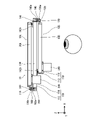
- FIG. 19 is a front view showing a schematic configuration of the image display unit.
- 20 is a top view of the image display unit shown in FIG. 19.
- FIG. 21 is a cross-sectional view taken along line 21-21 of FIG. 19.
- FIG. 22 is a cross-sectional view taken along line 22-22 of FIG. 19.
- FIG. 23 is a cross-sectional view taken along line 23-23 of FIG. 19.
- image display unit 10 of the present embodiment two units are individually held so that their tilts can be adjusted.
- the first unit 10A is attached to the base frame 130 using the first unit position adjusting screws 160 .
- the first unit position adjusting screw 160 is an example of a fastening member.
- the first frame main body 112 is provided with first frame screwing portions 116a, 116b, and 116c at three locations on the outer peripheral portion.
- the arrangement of the three first frame screwing portions 116a, 116b, 116c is as follows. That is, the first frame screwing portion 116a indicated by reference numeral 116a is provided at the center of the left side of the first frame main body 112 in FIG.
- the first frame screwing portion 116b indicated by reference numeral 116b is provided at the right end of the upper side of the first frame main body 112 in FIG.
- the first frame screwing portion 116c indicated by reference numeral 116c is provided at the left end of the lower side of the first frame main body 112 in FIG.
- Each of the first frame screwing portions 116a, 116b, 116c is provided with a hole 118 through which the first unit position adjusting screw 160 is passed.
- Each hole 118 has an inner diameter ⁇ 2 larger than the outer diameter ⁇ 1 of the first unit position adjusting screw 160 ( ⁇ 1 ⁇ 2). That is, each hole 118 has a gap (so-called “play”) with respect to the first unit position adjusting screw 160 when the first unit position adjusting screw 160 is passed therethrough.
- the base frame 130 is provided with first unit mounting portions 162a, 162b, and 162c at three locations on the front side surface.
- Each of the first unit mounting portions 162a, 162b, 162c is configured by a columnar projection and arranged on the same plane.
- the arrangement of the first unit mounting portions 162a, 162b, 162c is the same as the arrangement of the three first frame screwing portions 116a, 116b, 116c provided in the first frame main body 112. As shown in FIG.
- a screw hole 164 is provided in each of the first unit mounting portions 162a, 162b, 162c.
- a screw hole 164 is centrally located on the top of each first unit mounting portion 162a, 162b, 162c.
- the screw hole 164 has a dimension corresponding to the first unit position adjusting screw 160 and is arranged along the depth direction (Z-axis direction).
- the first unit position adjusting screws 160 are passed through the holes 118 of the first frame screwing portions 116a, 116b, and 116c, and the screws of the first unit mounting portions 162a, 162b, and 162c of the base frame 130 are inserted.
- the first unit position adjusting screw 160 By fitting the first unit position adjusting screw 160 into the hole 164 , it is attached to the base frame 130 .
- the first unit 10A is attached to the base frame 130 with a first unit biasing spring 166 interposed therebetween.
- the first unit biasing spring 166 is composed of, for example, a coil spring.
- the first unit position adjusting screw 160 is passed through the inner periphery of the first unit biasing spring 166, and the first unit mounting portions 162a, 162b, 162c and the first frame screwing portions 116a, 116b, 116c are connected. is placed between The first unit biasing spring 166 is an example of a biasing member.
- the first unit urging springs 166 are interposed between the first unit mounting portions 162a, 162b, and 162c at the first frame screwing portions 116a, 116b, and 116c. , attached to the base frame 130 .
- the function of adjusting the inclination of the first unit 10A with respect to the base frame 130 is realized.
- the tilt is adjusted as follows.
- the first unit position adjusting screw 160 is loosened in each of the first frame screwing portions 116a, 116b, and 116c, the first unit 10A separates from the base frame 130 at the loosened portion.
- the first unit position adjusting screw 160 is tightened, the first unit 10A approaches the base frame 130 at the tightened location.
- the tilt can be adjusted. For example, in FIG. 21, when the first unit position adjusting screw 160 of the first frame screwing portion 116a indicated by reference numeral 116a is turned, the entire first unit 10A is tilted around the Y axis.
- the first unit 10A adjusts the inclination with respect to the base frame 130 by individually adjusting the tightening amounts of the first unit position adjusting screws 160 at the first frame screwing portions 116a, 116b, and 116c. can.
- the inclination relative to the second unit 10B attached to the base frame 130 can be adjusted.
- the holding structure of the second unit 10B is the same as that of the image display unit 10 of the first embodiment. Therefore, description of the configuration is omitted.
- the first unit 10A and the second unit 10B are assembled. That is, the first display image light input device 20A and the first light guide plate 30A are assembled to the first frame 110 . Also, the second display image light input device 20B and the second light guide plate 30B are assembled to the second frame 120 .
- first unit 10A and the second unit 10B are assembled to the base frame 130.
- the first unit 10A is attached to the base frame.
- the first unit 10A is attached to the base frame 130 by screwing the first unit position adjusting screws 160 to the three first frame screwing portions 116a, 116b, and 116c.
- the first unit biasing spring 166 is interposed between each of the first frame screwing portions 116a, 116b, and 116c and the base frame 130 for attachment.
- the second unit 10B is attached to the base frame.
- the second unit 10B is attached to the base frame 130 by screwing the second unit tilt adjusting screws 140 to the three second frame screwing portions 126a, 126b, and 126c.
- the second unit biasing spring 146 is interposed between each of the second frame screwing portions 126a, 126b, 126c and the base frame 130 for attachment.
- the fixation is performed, for example, by bonding each first frame screwing portion 116a, 116b, 116c and each second frame screwing portion 126a, 126b, 126c to the base frame 130 using an adhesive.
- the image display unit 10 is incorporated into the lens portion of the spectacle-shaped frame that constitutes the head-mounted image display device 1, and the head-mounted image display device 1 is completed.
- the image display unit 10 of the present embodiment when using two units to generate a synthesized image, the arrangement relationship between the two units can be adjusted. This allows post hoc correction even if the images from the two units do not stitch together correctly at the stage of assembly. Thereby, a high-quality image can be presented. In addition, required part accuracy and assembly accuracy can be reduced.
- the two units are individually held so that their inclinations can be adjusted. Thereby, the degree of freedom of adjustment can be improved.
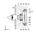
- FIG. 24 is a front view showing a schematic configuration of a modification of the image display unit.
- 25 is a rear view of the image display unit shown in FIG. 24.
- FIG. 26 is a top view showing a schematic configuration of the image display unit shown in FIG. 24.
- FIG. 27 is a cross-sectional view taken along line 27-27 of FIG. 24.
- the image display unit of the above embodiment has a configuration in which the first unit 10A and the second unit 10B are arranged so as to overlap one side surface (front side surface) of the base frame 130 . More specifically, the light guide plate of each unit has a configuration in which the light guide plate is arranged to overlap one side of the base frame 130 .
- the first unit 10A and the second unit 10B are arranged to overlap each other with the base frame 130 interposed therebetween. More specifically, the light guide plates of each unit are arranged to overlap each other with the base frame 130 interposed therebetween.
- FIG. 24 is an example in which the front side surface of the base frame 130 holds the second unit 10B and the rear side surface holds the first unit 10A.
- the front side surface of the base frame 130 is provided with second unit attachment portions 142a, 142b, and 142c, and the rear side surface is provided with first unit attachment portions 162a, 162b, and 162c.
- At least one of the units may have a mechanism for individually adjusting the relative positional relationship between the light guide plate and the display image light input device.
- each unit may include a mechanism for adjusting the tilt and/or position of the display image light input device.
- the image displayed on the display element of each unit is observed through the light guide plate.
- Light of an image displayed on the display device (display image light) is input to a predetermined position of the light guide plate via the input optical system. Therefore, by adjusting this input position, the position of the image observed through each unit can be adjusted.
- the position at which the display image light is input can be adjusted by changing the position of the image displayed on the display device, as well as by mechanical adjustment as in the image display unit of the third embodiment.
- the position of the image displayed on the display element is adjusted, for example, by changing the position of the image displayed within the display area of the display element. Therefore, in this case, an image is displayed using part of the display area of the display element.
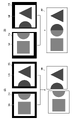
- FIG. 28 is a conceptual diagram for electronically adjusting the synthesized state of the observed images.
- FIG. 1A is a diagram showing the relationship between the display images ImA and ImB of each display element before adjustment and the observed image ImC.
- FIG. 1B is a diagram showing the relationship between the display images ImA and ImB of each display element after adjustment and the observed image ImC.
- the positions of the images to be displayed on the first display element 21A and the second display element 21B are adjusted. That is, as shown in FIG. 28B, the positions of the display image ImA and the display image ImB displayed on the first display element 21A and the second display element 21B are adjusted so that the two images are seamlessly synthesized. .
- FIG. 29 is a block diagram showing the electrical configuration of the image display unit.
- the image display unit 10 of the present embodiment has an image input section 400, a first display element driving section 410A, a second display element driving section 410B, a display control section 420 and an operation section 430.
- the image input unit 400 inputs an image to be displayed on the image display unit.
- Image input is performed by wire or wirelessly.
- the first display element driving section 410A drives the first display element 21A to display an image in the display area of the first display element 21A.
- the second display element driving section 410B drives the second display element 21B to display an image in the display area of the second display element 21B.
- the display control unit 420 generates an image to be displayed on each display element from the image input to the image input unit 400, and causes each display element to display the image.
- display control section 420 adjusts the position of the image to be displayed in the display area of each display element according to an instruction from operation section 430 . Therefore, the operation unit 430 has at least a function of instructing movement of the position of the image to be displayed on each display element.
- the operation unit 430 can also be composed of, for example, a so-called remote controller.
- FIG. 30 is a block diagram of functions possessed by the display control unit.
- the display control unit 420 has the functions of a display image generation unit 422, a first image display control unit 424A and a second image display control unit 424B.
- the display image generation unit 422 generates an image to be displayed on the first display element 21A and the second display element 21B from the image input to the image input unit 400.
- An image displayed on the first display element 21A is referred to as a first image
- an image displayed on the second display element 21B is referred to as a second image.
- the first image display control section 424A displays the first image generated by the display image generation section 422 on the first display element 21A. Further, the first image display control unit 424A receives an instruction to move the image display position from the operation unit 430, and moves the image display position according to the received instruction.
- the second image display control section 424B displays the second image generated by the display image generation section 422 on the second display element 21B. Further, the second image display control unit 424B receives an instruction to move the image display position from the operation unit 430, and moves the image display position according to the received instruction.
- the display control unit 420 is composed of a computer having a processor and memory, and each function described above is realized by the processor executing a predetermined program.
- Processors include CPU (Central Processing Unit), which is a general-purpose processor, Programmable Logic Device (PLD), which is a processor whose circuit configuration can be changed after manufacturing, such as FPGA (Field Programmable Gate Array), ASIC ( Application Specific Integrated Circuit), a dedicated electric circuit, etc., which is a processor with a circuit configuration specially designed to execute specific processing.
- the display control unit 420 may be configured with one of these various processors, or with two or more processors of the same type or different types (for example, multiple FPGAs, or a combination of a CPU and an FPGA). may be configured. In this way, the display control unit 420 is configured using one or more of the above-described various processors as a hardware structure. Further, the hardware structure of these various processors is, more specifically, an electric circuit combining circuit elements such as semiconductor elements.
- Adjustment of the viewed image is performed as follows.
- a predetermined test image is input to the image input unit 400, the image is displayed on each display unit, and the display state is confirmed.
- the image displayed on each display element is displayed at the origin position set in the display area of each display element.
- the origin position is set, for example, at the center of the display area of each display element.
- FIG. 27A when there is a shift between the two observed images, the display positions of the images are adjusted. That is, as shown in FIG. 27B, the position of the image displayed on each display element is adjusted so that the seam between the two images cannot be seen.
- the combined state of the images displayed on each unit can also be adjusted by adjusting the position of the image displayed on the display element of each unit.
- the mechanical adjustment mechanism can be omitted. That is, the mechanism for adjusting the relative positional relationship between the first unit and the second unit can be omitted.
- the first unit and the second unit are attached to the base frame in such a state that their inclination, position, etc. cannot be adjusted.
- the degree of freedom and width of adjustment can be increased, enabling more detailed alignment.
- the image display unit can be configured by combining two or more units. Therefore, for example, three units can be combined to form one image unit. In this case, the arrangement relationship is relatively adjusted between each unit.
- the display image light input device is not limited to the display image light input device of the above embodiment, and display image light input devices having various configurations can be used.
- a display image light input device using laser light can be used.
- a display image light input device using a laser beam generates an image by scanning the laser beam.
- an image is generated by emitting laser light from the tip of the fiber and scanning the tip of the fiber.
- an image is generated by scanning the laser light output from the light source section with a scanning mirror.
- FIG. 31 is a diagram showing another example of the light guide plate.
- the light guide plate 500 shown in the figure is a light guide plate configured such that the display image light input to the input section 502 is propagated in the vertical direction, then propagated in the horizontal direction, and output from the output section 504 . According to the light guide plate 500 having this configuration, the input position of the image display light can be adjusted.
- a light guide plate using a diffraction grating can be used as the light guide plate.
Landscapes
- Physics & Mathematics (AREA)
- General Physics & Mathematics (AREA)
- Optics & Photonics (AREA)
- Engineering & Computer Science (AREA)
- Multimedia (AREA)
- Signal Processing (AREA)
- Devices For Indicating Variable Information By Combining Individual Elements (AREA)
Abstract
Description
ここでは、本発明を頭部装着型画像表示装置に適用した場合を例に説明する。
図2は、画像表示ユニットの概略構成を示す図である。
まず、画像表示ユニット10を構成する2つのユニットの構成について説明する。
図3は、第1ユニットの概略構成を示す斜視図である。図4は、第1ユニットの概略構成を示す正面図である。なお、ここでの正面とは、観察者が画像を観察する際に観察者の眼と対向する面である。図5は、第1ユニットの概略構成を示す上面図である。図6は、第1ユニットの概略構成を示す側面図である。なお、各図において、導光板の長辺方向をX軸方向、短辺方向をY軸方向、厚さ方向をZ軸方向としている。X軸方向は、画像を観察する際の横方向(左右方向)であり、Y軸方向は、画像を観察する際の縦方向(上下方向)である。また、Z軸方向は、画像を観察する際の奥行向(前後方向)である。
図7は、第2ユニットの概略構成を示す斜視図である。基本的な構成は、第1ユニット10Aと同じである。
上記のように、画像表示ユニット10は、2つのユニットを組み合わせて構成される。具体的には、第1ユニット10A及び第2ユニット10Bを所定の配置関係で重ね合わせて配置することにより構成される。この配置関係は、各ユニットで表示される画像が合成されて、1つの画像として観察される配置関係である。より具体的には、各ユニットで表示される画像が横方向(X軸方向)に繋ぎ合わされて、1つの画像として観察される配置関係である。いわゆる横方向にパノラマ合成される配置関係である。
上記のように、画像表示ユニット10は、2つのユニットを所定の配置関係で配置することにより、各ユニットで表示される画像が合成されて、1つの画像として観察される。その一方で、2つのユニットが所定の配置関係で配置されていないと、観察される画像に繋ぎ目が現れ、品質を著しく低下させる。しかし、2つのユニットを所定の配置関係で正確に組み付けることは難しい。また、正確に組み付けるには、高い部品精度が要求される。このため、本実施の形態の画像表示ユニット10には、2つのユニットの配置関係を調節する機構(調節機構)が備えられる。
本実施の形態の画像表示ユニット10は、次のように組み立てられる。
上記のように、第2ユニット10Bは、各第2フレームネジ止め部126a、126b、126cにおいて、第2ユニット取付部142a、142b、142cとの間隔を個別に調節することで、傾きが調節される。各第2フレームネジ止め部126a、126b、126cにおいて、第2ユニット取付部142a、142b、142cとの間隔を調節する機構は、上記実施の形態のものに限定されるものではない。種々の構成を採用できる。
上記第1の実施の形態の画像表示ユニットでは、2つのユニットとの間で相対的に傾きを調節できる構成とされている。本実施の形態の画像表示ユニットでは、更に、平面的な位置を調節できる構成とする。すなわち、シフト量を調節できる構成とする。
図16は、画像表示ユニットの概略構成を示す正面図である。
ここでは、第2ユニット10Bの位置の調節方法について説明する。
観察される画像の合成状態は、導光板と表示画像光入力装置との間の配置関係によっても調節できる。
図19は、画像表示ユニットの概略構成を示す正面図である。図20は、図19に示す画像表示ユニットの上面図である。図21は、図19の21-21断面図である。図22は、図19の22-22断面図である。図23は、図19の23-23断面図である。
第1ユニット10Aは、第1ユニット位置調節用ネジ160を利用して、ベースフレーム130に取り付けられる。第1ユニット位置調節用ネジ160は、締結部材の一例である。
第2ユニット10Bの保持構造は、上記第1の実施の形態の画像表示ユニット10と同じである。したがって、その構成についての説明は省略する。
本実施の形態の画像表示ユニット10は、次のように組み立てられる。
[第1ユニットと第2ユニットの配置の変形例]
図24は、画像表示ユニットの変形例の概略構成を示す正面図である。図25は、図24に示す画像表示ユニットの背面図である。図26は、図24に示す画像表示ユニットの概略構成を示す上面図である。図27は、図24の27-27断面図である。
各ユニットの傾きを調節する機構に加えて、又は、傾きを調節する機構に代えて、各ユニットの位置を調節する機構を備えてもよい。
本実施の形態では、観察される画像の合成状態を電子的に調節する場合の例について説明する。
図29は、画像表示ユニットの電気的な構成を示すブロック図である。
観察される画像の調節は、次のように行われる。
本実施の形態の画像表示ユニットのように、観察される画像の合成状態を電子的に調節する場合、機械的な調節機構を省くこともできる。すなわち、第1ユニットと第2ユニットとの間の相対的な配置関係を調節する機構については省くことができる。この場合、第1ユニット及び第2ユニットは、ベースフレームに対し傾き及び位置等を調節不能な状態で取り付けられる。
[調節機構の組み合わせについて]
各実施の形態で説明した調節機構は、適宜組み合わせて使用できる。
上記実施の形態では、2つのユニットを組み合わせて1つの画像表示ユニットを構成する場合について説明したが、画像表示ユニットは、2以上のユニットを組み合わせて構成できる。したがって、たとえば3つのユニットを組み合わせて、1つの画像ユニットを構成することもできる。この場合は、各ユニット間で相対的に配置関係が調節される。
表示画像光入力装置については、上記実施の形態の表示画像光入力装置に限定されず、種々の構成の表示画像光入力装置を使用できる。たとえば、レーザ光を使用した表示画像光入力装置を使用することができる。レーザ光を使用した表示画像光入力装置では、レーザ光を走査させることで画像を生成する。たとえば、ファイバの先端からレーザ光を出射し、ファイバの先端を走査することによって、画像を生成する。あるいは、光源部が出力したレーザ光を走査ミラーで走査させることで画像を生成する。
図31は、導光板の他の一例を示す図である。
上記実施の形態では、いわゆる眼鏡型の頭部装着型画像表示装置に本発明を適用した場合を例に説明したが、本発明が適用される画像表示装置は、これに限定されるものではない。眼前に配置されて画像を観察する構成の画像表示装置に広く適用できる。
2 フレーム
10 画像表示ユニット
10A 第1ユニット
10B 第2ユニット
20A 第1表示画像光入力装置
20B 第2表示画像光入力装置
20b 第2表示画像光入力装置の筐体
21A 第1表示素子
21B 第2表示素子
22A 第1入力光学系
22B 第2入力光学系
30A 第1導光板
30B 第2導光板
31A 第1導光板の第1入力部
31B 第2導光板の第2入力部
32A 第1導光板の第1出力部
32B 第2導光板の第2出力部
33A 第1導光板の第1入力面
33B 第2導光板の第2入力面
34A 第1導光板のミラー
34B 第2導光板のミラー
35A 第1導光板の第1出力面
35B 第2導光板の第2出力面
36A 第1導光板のハーフミラー
36B 第2導光板のハーフミラー
110 第1フレーム
112 第1フレーム本体
122A ネジ当接部
114 第1表示画像光入力装置取付部
116a 第1フレームネジ止め部
116b 第1フレームネジ止め部
116c 第1フレームネジ止め部
118 第1フレームネジ止め部の穴
120 第2フレーム
122 第2フレーム本体
124 第2表示画像光入力装置取付部
126a 第2フレームネジ止め部
126b 第2フレームネジ止め部
126c 第2フレームネジ止め部
128 第2フレームネジ止め部の穴
130 ベースフレーム
132 ベースフレームの内周部
140 第2ユニット傾き調節用ネジ
142a 第2ユニット取付部
142b 第2ユニット取付部
142c 第2ユニット取付部
144 第2ユニット取付部のネジ穴
146 第2ユニット付勢バネ
148 スペーサ
150 第1ユニット固定用ネジ
160 第1ユニット位置調節用ネジ
162a 第1ユニット取付部
162b 第1ユニット取付部
162c 第1ユニット取付部
164 第1ユニット取付部のネジ穴
166 第1ユニット付勢バネバネ
210 横位置調節機構
212 横方向付勢バネ
214 横位置調節ネジ
216 ブラケット
218 ブラケット
220 縦位置調節機構
222 縦方向付勢バネ
224 縦位置調節ネジ
226 ブラケット
228 ブラケット
300 傾き調節機構
302 第2表示画像光入力装置ネジ止め部
304 第2表示画像光入力装置ネジ止め部の穴
306 第2表示画像光入力装置位置調節用ネジ
308 第2表示画像光入力装置取付部のネジ穴
310 第2表示画像光入力装置付勢バネ
400 画像入力部
410A 第1表示素子駆動部
410B 第2表示素子駆動部
420 表示制御部
422 表示画像生成部
424A 第1画像表示制御部
424B 第2画像表示制御部
430 操作部
500 導光板
502 導光板の入力部
504 導光板の出力部
ImA 第1表示素子の表示画像
ImB 第2表示素子の表示画像
ImC 観察画像
Claims (18)
- 表示画像光を入力する複数の表示画像光入力装置と、
重ね合わせて配置され、かつ、複数の前記表示画像光入力装置から個別に前記表示画像光が入力され、入力された前記表示画像光を個別に反射させながら出力面へ伝播する複数の導光板と、
複数の前記導光板の配置関係を調節する第1調節機構と、
を備えた画像表示装置。 - 前記第1調節機構は、複数の前記導光板の間で相対的に傾き、及び/又は、位置を調節する、
請求項1に記載の画像表示装置。 - 前記第1調節機構は、複数の前記導光板を重ねて保持する保持部材を含み、前記保持部材に対する複数の前記導光板の配置関係を個別に調節する、
請求項1又は2に記載の画像表示装置。 - 前記保持部材は、同一平面内に設定された複数の保持点で前記導光板を保持し、
前記第1調節機構は、各前記保持点において、前記導光板と前記保持部材との間隔を個別に調節して、前記保持部材に対する複数の前記導光板の配置関係を個別に調節する、
請求項3に記載の画像表示装置。 - 前記第1調節機構は、
各前記保持点において、前記導光板と前記保持部材とを締結する締結部材と、
各前記保持点において、前記導光板と前記保持部材とを互いに離間させる方向に付勢する付勢部材と、
で構成される、
請求項4に記載の画像表示装置。 - 前記第1調節機構は、
各前記保持点において、前記導光板と前記保持部材とを締結する締結部材と、
各前記保持点において、前記導光板と前記保持部材との間に配置されるスペーサ部材と、
で構成される、
請求項4に記載の画像表示装置。 - 複数の前記導光板が、前記保持部材の片側に重ね合わせて配置されて、前記保持部材に保持される、
請求項3から6のいずれか1項に記載の画像表示装置。 - 重ね合わされた各前記導光板の間に前記保持部材が配置されて、複数の導光板が前記保持部材に保持される、
請求項3から6のいずれか1項に記載の画像表示装置。 - 前記第1調節機構は、複数の前記導光板の間に挿入されるスペーサ部材を含み、前記スペーサ部材を挿入する位置、及び/又は、厚さを調節して、複数の前記導光板の相対的な配置関係を調節する、
請求項1又は2に記載の画像表示装置。 - 前記導光板に前記表示画像光入力装置が組み付けられ、前記第1調節機構による調節の際に、前記導光板と前記表示画像光入力装置とが互いに動かされる、
請求項1から9のいずれか1項に記載の画像表示装置。 - 前記第1調節機構による調節の際に、前記導光板が前記表示画像光入力装置から独立して動かされる、
請求項1から9のいずれか1項に記載の画像表示装置。 - 各前記導光板と前記表示画像光入力装置との間の相対的な配置関係を個別に調節する複数の第2調節機構を更に備える、
請求項1から9のいずれか1項に記載の画像表示装置。 - 前記第2調節機構は、前記導光板と前記表示画像光入力装置との間で相対的に傾き、及び/又は、位置を調節する、
請求項12に記載の画像表示装置。 - プロセッサを更に備え、
前記プロセッサは、
前記表示画像光入力装置が前記導光板に対し前記表示画像光を入力する位置の調節の指示を受け付け、
受け付けた調節の指示に従って、前記表示画像光入力装置が前記導光板に対し前記表示画像光を入力する位置を調節する、
請求項1から13のいずれか1項に記載の画像表示装置。 - 表示画像光を入力する複数の表示画像光入力装置と、
重ね合わせて配置され、かつ、複数の前記表示画像光入力装置から個別に前記表示画像光が入力され、入力された前記表示画像光を個別に反射させながら出力面へ伝播する複数の導光板と、
各前記導光板と前記表示画像光入力装置との間の配置関係を個別に調節する複数の第3調節機構と、
を備えた画像表示装置。 - 前記第3調節機構は、前記導光板と前記表示画像光入力装置との間で相対的に傾き、及び/又は、位置を調節する、
請求項15に記載の画像表示装置。 - プロセッサを更に備え、
前記プロセッサは、
前記表示画像光入力装置が前記導光板に対し前記表示画像光を入力する位置の調節の指示を受け付け、
受け付けた調節の指示に従って、前記表示画像光入力装置が前記導光板に対し前記表示画像光を入力する位置を調節する、
請求項15又は16に記載の画像表示装置。 - 表示画像光を入力する複数の表示画像光入力装置と、
重ね合わせて配置され、かつ、複数の前記表示画像光入力装置から個別に前記表示画像光が入力され、入力された前記表示画像光を個別に反射させながら出力面へ伝播する複数の導光板と、
プロセッサと、
を備え、
前記プロセッサは、
前記表示画像光入力装置が前記導光板に対し前記表示画像光を入力する位置の調節の指示を受け付け、
受け付けた調節の指示に従って、前記表示画像光入力装置が前記導光板に対し前記表示画像光を入力する位置を調節する、
画像表示装置。
Priority Applications (3)
| Application Number | Priority Date | Filing Date | Title |
|---|---|---|---|
| CN202280011848.7A CN116830016A (zh) | 2021-01-29 | 2022-01-26 | 图像显示装置 |
| JP2022578428A JPWO2022163672A1 (ja) | 2021-01-29 | 2022-01-26 | |
| US18/351,272 US20230359046A1 (en) | 2021-01-29 | 2023-07-12 | Image display apparatus |
Applications Claiming Priority (2)
| Application Number | Priority Date | Filing Date | Title |
|---|---|---|---|
| JP2021-013413 | 2021-01-29 | ||
| JP2021013413 | 2021-01-29 |
Related Child Applications (1)
| Application Number | Title | Priority Date | Filing Date |
|---|---|---|---|
| US18/351,272 Continuation US20230359046A1 (en) | 2021-01-29 | 2023-07-12 | Image display apparatus |
Publications (1)
| Publication Number | Publication Date |
|---|---|
| WO2022163672A1 true WO2022163672A1 (ja) | 2022-08-04 |
Family
ID=82653607
Family Applications (1)
| Application Number | Title | Priority Date | Filing Date |
|---|---|---|---|
| PCT/JP2022/002757 WO2022163672A1 (ja) | 2021-01-29 | 2022-01-26 | 画像表示装置 |
Country Status (4)
| Country | Link |
|---|---|
| US (1) | US20230359046A1 (ja) |
| JP (1) | JPWO2022163672A1 (ja) |
| CN (1) | CN116830016A (ja) |
| WO (1) | WO2022163672A1 (ja) |
Cited By (1)
| Publication number | Priority date | Publication date | Assignee | Title |
|---|---|---|---|---|
| JP7475757B2 (ja) | 2021-07-04 | 2024-04-30 | ルーマス リミテッド | 積層導光素子が視野の異なる部分を提供するディスプレイ |
Citations (7)
| Publication number | Priority date | Publication date | Assignee | Title |
|---|---|---|---|---|
| JP2004012768A (ja) * | 2002-06-06 | 2004-01-15 | Nikon Corp | コンバイナ光学系 |
| JP2012042654A (ja) * | 2010-08-18 | 2012-03-01 | Sony Corp | 表示装置 |
| JP2018011223A (ja) * | 2016-07-14 | 2018-01-18 | 株式会社リコー | 虚像表示装置 |
| JP2018054978A (ja) * | 2016-09-30 | 2018-04-05 | セイコーエプソン株式会社 | 虚像表示装置及びその製造方法 |
| US20180299678A1 (en) * | 2015-12-17 | 2018-10-18 | Carl Zeiss Ag | Optical system and method for transmitting a source image |
| JP2020064096A (ja) * | 2018-10-15 | 2020-04-23 | ソニー株式会社 | 画像表示装置、頭部装着型ディスプレイ、画像表示装置の製造方法、及び画像表示装置の調整方法 |
| JP2020112713A (ja) * | 2019-01-15 | 2020-07-27 | ブルーオプテック株式会社 | ウエアラブル画像表示装置 |
-
2022
- 2022-01-26 JP JP2022578428A patent/JPWO2022163672A1/ja active Pending
- 2022-01-26 WO PCT/JP2022/002757 patent/WO2022163672A1/ja active Application Filing
- 2022-01-26 CN CN202280011848.7A patent/CN116830016A/zh active Pending
-
2023
- 2023-07-12 US US18/351,272 patent/US20230359046A1/en active Pending
Patent Citations (7)
| Publication number | Priority date | Publication date | Assignee | Title |
|---|---|---|---|---|
| JP2004012768A (ja) * | 2002-06-06 | 2004-01-15 | Nikon Corp | コンバイナ光学系 |
| JP2012042654A (ja) * | 2010-08-18 | 2012-03-01 | Sony Corp | 表示装置 |
| US20180299678A1 (en) * | 2015-12-17 | 2018-10-18 | Carl Zeiss Ag | Optical system and method for transmitting a source image |
| JP2018011223A (ja) * | 2016-07-14 | 2018-01-18 | 株式会社リコー | 虚像表示装置 |
| JP2018054978A (ja) * | 2016-09-30 | 2018-04-05 | セイコーエプソン株式会社 | 虚像表示装置及びその製造方法 |
| JP2020064096A (ja) * | 2018-10-15 | 2020-04-23 | ソニー株式会社 | 画像表示装置、頭部装着型ディスプレイ、画像表示装置の製造方法、及び画像表示装置の調整方法 |
| JP2020112713A (ja) * | 2019-01-15 | 2020-07-27 | ブルーオプテック株式会社 | ウエアラブル画像表示装置 |
Cited By (1)
| Publication number | Priority date | Publication date | Assignee | Title |
|---|---|---|---|---|
| JP7475757B2 (ja) | 2021-07-04 | 2024-04-30 | ルーマス リミテッド | 積層導光素子が視野の異なる部分を提供するディスプレイ |
Also Published As
| Publication number | Publication date |
|---|---|
| CN116830016A (zh) | 2023-09-29 |
| JPWO2022163672A1 (ja) | 2022-08-04 |
| US20230359046A1 (en) | 2023-11-09 |
Similar Documents
| Publication | Publication Date | Title |
|---|---|---|
| CN203825293U (zh) | 虚像显示装置 | |
| US8446340B2 (en) | Device and method for alignment of binocular personal display | |
| JP4325724B2 (ja) | ヘッドアップディスプレイ装置 | |
| WO2010116726A1 (ja) | ビーム走査型表示装置 | |
| CN106019585B (zh) | 头部佩戴型显示器 | |
| JP2008535001A (ja) | 内部全反射イメージを使用する光学システム | |
| WO2022163672A1 (ja) | 画像表示装置 | |
| TW201708884A (zh) | 圖像顯示裝置 | |
| CN113646688B (zh) | 具有多个光引擎的扫描投影仪显示器 | |
| JP2010122478A (ja) | 映像表示装置およびヘッドマウントディスプレイ | |
| JP6687016B2 (ja) | ウェアラブルディスプレイ、ウェアラブルディスプレイ用筐体及びウェアラブルディスプレイの製造方法 | |
| US11675196B2 (en) | Wearable device with image display module | |
| JP5242477B2 (ja) | 眼鏡装着型画像表示装置 | |
| JP2009134087A (ja) | 映像表示装置およびヘッドマウントディスプレイ | |
| JP2017227682A (ja) | ミラー構造体およびヘッドアップディスプレイ装置 | |
| JPWO2022163672A5 (ja) | ||
| JP2005532597A (ja) | 表示装置 | |
| JP2010097001A (ja) | 双眼鏡 | |
| JP6455449B2 (ja) | ヘッドマウントディスプレイ | |
| KR20230114755A (ko) | 프로젝터 정렬 시스템 | |
| CN112444987A (zh) | 显示装置以及显示装置的光学系统的调整方法 | |
| CN114815245B (zh) | 图像显示装置 | |
| JP6206295B2 (ja) | 傾き調整機構を備えた光学機器及び傾き調整方法 | |
| JP7350626B2 (ja) | 光学機器 | |
| US20240061256A1 (en) | Head-mounted display apparatus, optical unit, and manufacturing method of optical unit |
Legal Events
| Date | Code | Title | Description |
|---|---|---|---|
| 121 | Ep: the epo has been informed by wipo that ep was designated in this application |
Ref document number: 22745892 Country of ref document: EP Kind code of ref document: A1 |
|
| ENP | Entry into the national phase |
Ref document number: 2022578428 Country of ref document: JP Kind code of ref document: A |
|
| WWE | Wipo information: entry into national phase |
Ref document number: 202280011848.7 Country of ref document: CN |
|
| NENP | Non-entry into the national phase |
Ref country code: DE |
|
| 122 | Ep: pct application non-entry in european phase |
Ref document number: 22745892 Country of ref document: EP Kind code of ref document: A1 |