WO2022163572A1 - Cbn sintered compact - Google Patents
Cbn sintered compact Download PDFInfo
- Publication number
- WO2022163572A1 WO2022163572A1 PCT/JP2022/002411 JP2022002411W WO2022163572A1 WO 2022163572 A1 WO2022163572 A1 WO 2022163572A1 JP 2022002411 W JP2022002411 W JP 2022002411W WO 2022163572 A1 WO2022163572 A1 WO 2022163572A1
- Authority
- WO
- WIPO (PCT)
- Prior art keywords
- cbn
- sintered body
- tial
- cbn sintered
- binder phase
- Prior art date
Links
- 239000011230 binding agent Substances 0.000 claims abstract description 27
- 229910052749 magnesium Inorganic materials 0.000 claims abstract description 26
- 229910052710 silicon Inorganic materials 0.000 claims abstract description 26
- 229910052725 zinc Inorganic materials 0.000 claims abstract description 25
- 229910004349 Ti-Al Inorganic materials 0.000 claims abstract description 18
- 229910004692 Ti—Al Inorganic materials 0.000 claims abstract description 18
- 229910045601 alloy Inorganic materials 0.000 claims abstract description 18
- 239000000956 alloy Substances 0.000 claims abstract description 18
- 229910052782 aluminium Inorganic materials 0.000 claims abstract description 14
- 229910052719 titanium Inorganic materials 0.000 claims abstract description 14
- 238000000682 scanning probe acoustic microscopy Methods 0.000 claims abstract description 10
- 229910010038 TiAl Inorganic materials 0.000 claims description 23
- 229910052582 BN Inorganic materials 0.000 claims description 8
- PZNSFCLAULLKQX-UHFFFAOYSA-N Boron nitride Chemical compound N#B PZNSFCLAULLKQX-UHFFFAOYSA-N 0.000 claims description 8
- 238000013507 mapping Methods 0.000 claims description 7
- 229910018072 Al 2 O 3 Inorganic materials 0.000 claims description 6
- PNEYBMLMFCGWSK-UHFFFAOYSA-N aluminium oxide Inorganic materials [O-2].[O-2].[O-2].[Al+3].[Al+3] PNEYBMLMFCGWSK-UHFFFAOYSA-N 0.000 abstract description 3
- 229910052593 corundum Inorganic materials 0.000 abstract description 3
- 229910001845 yogo sapphire Inorganic materials 0.000 abstract description 3
- QYEXBYZXHDUPRC-UHFFFAOYSA-N B#[Ti]#B Chemical compound B#[Ti]#B QYEXBYZXHDUPRC-UHFFFAOYSA-N 0.000 abstract description 2
- 229910033181 TiB2 Inorganic materials 0.000 abstract description 2
- 229910017083 AlN Inorganic materials 0.000 abstract 1
- 239000002245 particle Substances 0.000 description 57
- 239000010936 titanium Substances 0.000 description 38
- 239000000843 powder Substances 0.000 description 29
- 238000005520 cutting process Methods 0.000 description 22
- 239000002994 raw material Substances 0.000 description 22
- 238000005553 drilling Methods 0.000 description 16
- 235000013339 cereals Nutrition 0.000 description 11
- 239000011435 rock Substances 0.000 description 10
- 230000000052 comparative effect Effects 0.000 description 8
- 230000007423 decrease Effects 0.000 description 7
- 238000010438 heat treatment Methods 0.000 description 7
- 238000012545 processing Methods 0.000 description 7
- 238000002156 mixing Methods 0.000 description 6
- 238000005245 sintering Methods 0.000 description 6
- CSCPPACGZOOCGX-UHFFFAOYSA-N Acetone Chemical compound CC(C)=O CSCPPACGZOOCGX-UHFFFAOYSA-N 0.000 description 4
- 239000000463 material Substances 0.000 description 4
- 229910000838 Al alloy Inorganic materials 0.000 description 3
- 229910010039 TiAl3 Inorganic materials 0.000 description 3
- 238000004458 analytical method Methods 0.000 description 3
- 239000002131 composite material Substances 0.000 description 3
- 239000000203 mixture Substances 0.000 description 3
- 239000000126 substance Substances 0.000 description 3
- ZOXJGFHDIHLPTG-UHFFFAOYSA-N Boron Chemical compound [B] ZOXJGFHDIHLPTG-UHFFFAOYSA-N 0.000 description 2
- 229910004298 SiO 2 Inorganic materials 0.000 description 2
- 229910010413 TiO 2 Inorganic materials 0.000 description 2
- 238000009412 basement excavation Methods 0.000 description 2
- 229910052796 boron Inorganic materials 0.000 description 2
- 230000001186 cumulative effect Effects 0.000 description 2
- 239000010730 cutting oil Substances 0.000 description 2
- 238000000354 decomposition reaction Methods 0.000 description 2
- 238000010586 diagram Methods 0.000 description 2
- -1 ferrous metals Chemical class 0.000 description 2
- 238000010191 image analysis Methods 0.000 description 2
- 238000000034 method Methods 0.000 description 2
- 238000012360 testing method Methods 0.000 description 2
- XLYOFNOQVPJJNP-UHFFFAOYSA-N water Substances O XLYOFNOQVPJJNP-UHFFFAOYSA-N 0.000 description 2
- 229910001018 Cast iron Inorganic materials 0.000 description 1
- 229910017625 MgSiO Inorganic materials 0.000 description 1
- 240000007594 Oryza sativa Species 0.000 description 1
- 235000007164 Oryza sativa Nutrition 0.000 description 1
- 229910052581 Si3N4 Inorganic materials 0.000 description 1
- ATJFFYVFTNAWJD-UHFFFAOYSA-N Tin Chemical compound [Sn] ATJFFYVFTNAWJD-UHFFFAOYSA-N 0.000 description 1
- 230000003213 activating effect Effects 0.000 description 1
- 238000005054 agglomeration Methods 0.000 description 1
- 230000002776 aggregation Effects 0.000 description 1
- QVGXLLKOCUKJST-UHFFFAOYSA-N atomic oxygen Chemical compound [O] QVGXLLKOCUKJST-UHFFFAOYSA-N 0.000 description 1
- 230000015572 biosynthetic process Effects 0.000 description 1
- 239000000919 ceramic Substances 0.000 description 1
- 238000006243 chemical reaction Methods 0.000 description 1
- 150000001875 compounds Chemical class 0.000 description 1
- 239000000470 constituent Substances 0.000 description 1
- 230000007797 corrosion Effects 0.000 description 1
- 238000005260 corrosion Methods 0.000 description 1
- 230000007547 defect Effects 0.000 description 1
- 229910003460 diamond Inorganic materials 0.000 description 1
- 239000010432 diamond Substances 0.000 description 1
- 229910052634 enstatite Inorganic materials 0.000 description 1
- 230000008020 evaporation Effects 0.000 description 1
- 238000001704 evaporation Methods 0.000 description 1
- 238000010304 firing Methods 0.000 description 1
- 239000010438 granite Substances 0.000 description 1
- 239000012535 impurity Substances 0.000 description 1
- XEEYBQQBJWHFJM-UHFFFAOYSA-N iron Substances [Fe] XEEYBQQBJWHFJM-UHFFFAOYSA-N 0.000 description 1
- 238000003754 machining Methods 0.000 description 1
- 238000005259 measurement Methods 0.000 description 1
- 229910052751 metal Inorganic materials 0.000 description 1
- 239000002184 metal Substances 0.000 description 1
- 238000012986 modification Methods 0.000 description 1
- 230000004048 modification Effects 0.000 description 1
- 238000000465 moulding Methods 0.000 description 1
- 229910052760 oxygen Inorganic materials 0.000 description 1
- 239000001301 oxygen Substances 0.000 description 1
- 239000002243 precursor Substances 0.000 description 1
- 238000002360 preparation method Methods 0.000 description 1
- 230000009257 reactivity Effects 0.000 description 1
- 235000009566 rice Nutrition 0.000 description 1
- 239000000523 sample Substances 0.000 description 1
- 238000007790 scraping Methods 0.000 description 1
- 241000894007 species Species 0.000 description 1
- 150000003609 titanium compounds Chemical class 0.000 description 1
- 238000013519 translation Methods 0.000 description 1
Images


Classifications
-
- C—CHEMISTRY; METALLURGY
- C04—CEMENTS; CONCRETE; ARTIFICIAL STONE; CERAMICS; REFRACTORIES
- C04B—LIME, MAGNESIA; SLAG; CEMENTS; COMPOSITIONS THEREOF, e.g. MORTARS, CONCRETE OR LIKE BUILDING MATERIALS; ARTIFICIAL STONE; CERAMICS; REFRACTORIES; TREATMENT OF NATURAL STONE
- C04B35/00—Shaped ceramic products characterised by their composition; Ceramics compositions; Processing powders of inorganic compounds preparatory to the manufacturing of ceramic products
- C04B35/515—Shaped ceramic products characterised by their composition; Ceramics compositions; Processing powders of inorganic compounds preparatory to the manufacturing of ceramic products based on non-oxide ceramics
- C04B35/58—Shaped ceramic products characterised by their composition; Ceramics compositions; Processing powders of inorganic compounds preparatory to the manufacturing of ceramic products based on non-oxide ceramics based on borides, nitrides, i.e. nitrides, oxynitrides, carbonitrides or oxycarbonitrides or silicides
- C04B35/583—Shaped ceramic products characterised by their composition; Ceramics compositions; Processing powders of inorganic compounds preparatory to the manufacturing of ceramic products based on non-oxide ceramics based on borides, nitrides, i.e. nitrides, oxynitrides, carbonitrides or oxycarbonitrides or silicides based on boron nitride
- C04B35/5831—Shaped ceramic products characterised by their composition; Ceramics compositions; Processing powders of inorganic compounds preparatory to the manufacturing of ceramic products based on non-oxide ceramics based on borides, nitrides, i.e. nitrides, oxynitrides, carbonitrides or oxycarbonitrides or silicides based on boron nitride based on cubic boron nitrides or Wurtzitic boron nitrides, including crystal structure transformation of powder
-
- C—CHEMISTRY; METALLURGY
- C22—METALLURGY; FERROUS OR NON-FERROUS ALLOYS; TREATMENT OF ALLOYS OR NON-FERROUS METALS
- C22C—ALLOYS
- C22C26/00—Alloys containing diamond or cubic or wurtzitic boron nitride, fullerenes or carbon nanotubes
-
- C—CHEMISTRY; METALLURGY
- C04—CEMENTS; CONCRETE; ARTIFICIAL STONE; CERAMICS; REFRACTORIES
- C04B—LIME, MAGNESIA; SLAG; CEMENTS; COMPOSITIONS THEREOF, e.g. MORTARS, CONCRETE OR LIKE BUILDING MATERIALS; ARTIFICIAL STONE; CERAMICS; REFRACTORIES; TREATMENT OF NATURAL STONE
- C04B35/00—Shaped ceramic products characterised by their composition; Ceramics compositions; Processing powders of inorganic compounds preparatory to the manufacturing of ceramic products
- C04B35/622—Forming processes; Processing powders of inorganic compounds preparatory to the manufacturing of ceramic products
- C04B35/626—Preparing or treating the powders individually or as batches ; preparing or treating macroscopic reinforcing agents for ceramic products, e.g. fibres; mechanical aspects section B
- C04B35/63—Preparing or treating the powders individually or as batches ; preparing or treating macroscopic reinforcing agents for ceramic products, e.g. fibres; mechanical aspects section B using additives specially adapted for forming the products, e.g.. binder binders
- C04B35/6303—Inorganic additives
- C04B35/6316—Binders based on silicon compounds
-
- C—CHEMISTRY; METALLURGY
- C04—CEMENTS; CONCRETE; ARTIFICIAL STONE; CERAMICS; REFRACTORIES
- C04B—LIME, MAGNESIA; SLAG; CEMENTS; COMPOSITIONS THEREOF, e.g. MORTARS, CONCRETE OR LIKE BUILDING MATERIALS; ARTIFICIAL STONE; CERAMICS; REFRACTORIES; TREATMENT OF NATURAL STONE
- C04B35/00—Shaped ceramic products characterised by their composition; Ceramics compositions; Processing powders of inorganic compounds preparatory to the manufacturing of ceramic products
- C04B35/622—Forming processes; Processing powders of inorganic compounds preparatory to the manufacturing of ceramic products
- C04B35/64—Burning or sintering processes
- C04B35/645—Pressure sintering
-
- B—PERFORMING OPERATIONS; TRANSPORTING
- B22—CASTING; POWDER METALLURGY
- B22F—WORKING METALLIC POWDER; MANUFACTURE OF ARTICLES FROM METALLIC POWDER; MAKING METALLIC POWDER; APPARATUS OR DEVICES SPECIALLY ADAPTED FOR METALLIC POWDER
- B22F5/00—Manufacture of workpieces or articles from metallic powder characterised by the special shape of the product
- B22F2005/001—Cutting tools, earth boring or grinding tool other than table ware
-
- C—CHEMISTRY; METALLURGY
- C04—CEMENTS; CONCRETE; ARTIFICIAL STONE; CERAMICS; REFRACTORIES
- C04B—LIME, MAGNESIA; SLAG; CEMENTS; COMPOSITIONS THEREOF, e.g. MORTARS, CONCRETE OR LIKE BUILDING MATERIALS; ARTIFICIAL STONE; CERAMICS; REFRACTORIES; TREATMENT OF NATURAL STONE
- C04B2235/00—Aspects relating to ceramic starting mixtures or sintered ceramic products
- C04B2235/02—Composition of constituents of the starting material or of secondary phases of the final product
- C04B2235/30—Constituents and secondary phases not being of a fibrous nature
- C04B2235/32—Metal oxides, mixed metal oxides, or oxide-forming salts thereof, e.g. carbonates, nitrates, (oxy)hydroxides, chlorides
- C04B2235/3205—Alkaline earth oxides or oxide forming salts thereof, e.g. beryllium oxide
- C04B2235/3206—Magnesium oxides or oxide-forming salts thereof
-
- C—CHEMISTRY; METALLURGY
- C04—CEMENTS; CONCRETE; ARTIFICIAL STONE; CERAMICS; REFRACTORIES
- C04B—LIME, MAGNESIA; SLAG; CEMENTS; COMPOSITIONS THEREOF, e.g. MORTARS, CONCRETE OR LIKE BUILDING MATERIALS; ARTIFICIAL STONE; CERAMICS; REFRACTORIES; TREATMENT OF NATURAL STONE
- C04B2235/00—Aspects relating to ceramic starting mixtures or sintered ceramic products
- C04B2235/02—Composition of constituents of the starting material or of secondary phases of the final product
- C04B2235/30—Constituents and secondary phases not being of a fibrous nature
- C04B2235/32—Metal oxides, mixed metal oxides, or oxide-forming salts thereof, e.g. carbonates, nitrates, (oxy)hydroxides, chlorides
- C04B2235/3284—Zinc oxides, zincates, cadmium oxides, cadmiates, mercury oxides, mercurates or oxide forming salts thereof
-
- C—CHEMISTRY; METALLURGY
- C04—CEMENTS; CONCRETE; ARTIFICIAL STONE; CERAMICS; REFRACTORIES
- C04B—LIME, MAGNESIA; SLAG; CEMENTS; COMPOSITIONS THEREOF, e.g. MORTARS, CONCRETE OR LIKE BUILDING MATERIALS; ARTIFICIAL STONE; CERAMICS; REFRACTORIES; TREATMENT OF NATURAL STONE
- C04B2235/00—Aspects relating to ceramic starting mixtures or sintered ceramic products
- C04B2235/02—Composition of constituents of the starting material or of secondary phases of the final product
- C04B2235/30—Constituents and secondary phases not being of a fibrous nature
- C04B2235/34—Non-metal oxides, non-metal mixed oxides, or salts thereof that form the non-metal oxides upon heating, e.g. carbonates, nitrates, (oxy)hydroxides, chlorides
- C04B2235/3418—Silicon oxide, silicic acids, or oxide forming salts thereof, e.g. silica sol, fused silica, silica fume, cristobalite, quartz or flint
-
- C—CHEMISTRY; METALLURGY
- C04—CEMENTS; CONCRETE; ARTIFICIAL STONE; CERAMICS; REFRACTORIES
- C04B—LIME, MAGNESIA; SLAG; CEMENTS; COMPOSITIONS THEREOF, e.g. MORTARS, CONCRETE OR LIKE BUILDING MATERIALS; ARTIFICIAL STONE; CERAMICS; REFRACTORIES; TREATMENT OF NATURAL STONE
- C04B2235/00—Aspects relating to ceramic starting mixtures or sintered ceramic products
- C04B2235/02—Composition of constituents of the starting material or of secondary phases of the final product
- C04B2235/30—Constituents and secondary phases not being of a fibrous nature
- C04B2235/34—Non-metal oxides, non-metal mixed oxides, or salts thereof that form the non-metal oxides upon heating, e.g. carbonates, nitrates, (oxy)hydroxides, chlorides
- C04B2235/3427—Silicates other than clay, e.g. water glass
- C04B2235/3436—Alkaline earth metal silicates, e.g. barium silicate
- C04B2235/3445—Magnesium silicates, e.g. forsterite
-
- C—CHEMISTRY; METALLURGY
- C04—CEMENTS; CONCRETE; ARTIFICIAL STONE; CERAMICS; REFRACTORIES
- C04B—LIME, MAGNESIA; SLAG; CEMENTS; COMPOSITIONS THEREOF, e.g. MORTARS, CONCRETE OR LIKE BUILDING MATERIALS; ARTIFICIAL STONE; CERAMICS; REFRACTORIES; TREATMENT OF NATURAL STONE
- C04B2235/00—Aspects relating to ceramic starting mixtures or sintered ceramic products
- C04B2235/02—Composition of constituents of the starting material or of secondary phases of the final product
- C04B2235/30—Constituents and secondary phases not being of a fibrous nature
- C04B2235/38—Non-oxide ceramic constituents or additives
- C04B2235/3817—Carbides
- C04B2235/3839—Refractory metal carbides
- C04B2235/3843—Titanium carbides
-
- C—CHEMISTRY; METALLURGY
- C04—CEMENTS; CONCRETE; ARTIFICIAL STONE; CERAMICS; REFRACTORIES
- C04B—LIME, MAGNESIA; SLAG; CEMENTS; COMPOSITIONS THEREOF, e.g. MORTARS, CONCRETE OR LIKE BUILDING MATERIALS; ARTIFICIAL STONE; CERAMICS; REFRACTORIES; TREATMENT OF NATURAL STONE
- C04B2235/00—Aspects relating to ceramic starting mixtures or sintered ceramic products
- C04B2235/02—Composition of constituents of the starting material or of secondary phases of the final product
- C04B2235/30—Constituents and secondary phases not being of a fibrous nature
- C04B2235/38—Non-oxide ceramic constituents or additives
- C04B2235/3852—Nitrides, e.g. oxynitrides, carbonitrides, oxycarbonitrides, lithium nitride, magnesium nitride
- C04B2235/3856—Carbonitrides, e.g. titanium carbonitride, zirconium carbonitride
-
- C—CHEMISTRY; METALLURGY
- C04—CEMENTS; CONCRETE; ARTIFICIAL STONE; CERAMICS; REFRACTORIES
- C04B—LIME, MAGNESIA; SLAG; CEMENTS; COMPOSITIONS THEREOF, e.g. MORTARS, CONCRETE OR LIKE BUILDING MATERIALS; ARTIFICIAL STONE; CERAMICS; REFRACTORIES; TREATMENT OF NATURAL STONE
- C04B2235/00—Aspects relating to ceramic starting mixtures or sintered ceramic products
- C04B2235/02—Composition of constituents of the starting material or of secondary phases of the final product
- C04B2235/30—Constituents and secondary phases not being of a fibrous nature
- C04B2235/38—Non-oxide ceramic constituents or additives
- C04B2235/3852—Nitrides, e.g. oxynitrides, carbonitrides, oxycarbonitrides, lithium nitride, magnesium nitride
- C04B2235/386—Boron nitrides
-
- C—CHEMISTRY; METALLURGY
- C04—CEMENTS; CONCRETE; ARTIFICIAL STONE; CERAMICS; REFRACTORIES
- C04B—LIME, MAGNESIA; SLAG; CEMENTS; COMPOSITIONS THEREOF, e.g. MORTARS, CONCRETE OR LIKE BUILDING MATERIALS; ARTIFICIAL STONE; CERAMICS; REFRACTORIES; TREATMENT OF NATURAL STONE
- C04B2235/00—Aspects relating to ceramic starting mixtures or sintered ceramic products
- C04B2235/02—Composition of constituents of the starting material or of secondary phases of the final product
- C04B2235/30—Constituents and secondary phases not being of a fibrous nature
- C04B2235/38—Non-oxide ceramic constituents or additives
- C04B2235/3852—Nitrides, e.g. oxynitrides, carbonitrides, oxycarbonitrides, lithium nitride, magnesium nitride
- C04B2235/3873—Silicon nitrides, e.g. silicon carbonitride, silicon oxynitride
-
- C—CHEMISTRY; METALLURGY
- C04—CEMENTS; CONCRETE; ARTIFICIAL STONE; CERAMICS; REFRACTORIES
- C04B—LIME, MAGNESIA; SLAG; CEMENTS; COMPOSITIONS THEREOF, e.g. MORTARS, CONCRETE OR LIKE BUILDING MATERIALS; ARTIFICIAL STONE; CERAMICS; REFRACTORIES; TREATMENT OF NATURAL STONE
- C04B2235/00—Aspects relating to ceramic starting mixtures or sintered ceramic products
- C04B2235/02—Composition of constituents of the starting material or of secondary phases of the final product
- C04B2235/30—Constituents and secondary phases not being of a fibrous nature
- C04B2235/38—Non-oxide ceramic constituents or additives
- C04B2235/3852—Nitrides, e.g. oxynitrides, carbonitrides, oxycarbonitrides, lithium nitride, magnesium nitride
- C04B2235/3886—Refractory metal nitrides, e.g. vanadium nitride, tungsten nitride
-
- C—CHEMISTRY; METALLURGY
- C04—CEMENTS; CONCRETE; ARTIFICIAL STONE; CERAMICS; REFRACTORIES
- C04B—LIME, MAGNESIA; SLAG; CEMENTS; COMPOSITIONS THEREOF, e.g. MORTARS, CONCRETE OR LIKE BUILDING MATERIALS; ARTIFICIAL STONE; CERAMICS; REFRACTORIES; TREATMENT OF NATURAL STONE
- C04B2235/00—Aspects relating to ceramic starting mixtures or sintered ceramic products
- C04B2235/02—Composition of constituents of the starting material or of secondary phases of the final product
- C04B2235/30—Constituents and secondary phases not being of a fibrous nature
- C04B2235/40—Metallic constituents or additives not added as binding phase
- C04B2235/402—Aluminium
-
- C—CHEMISTRY; METALLURGY
- C04—CEMENTS; CONCRETE; ARTIFICIAL STONE; CERAMICS; REFRACTORIES
- C04B—LIME, MAGNESIA; SLAG; CEMENTS; COMPOSITIONS THEREOF, e.g. MORTARS, CONCRETE OR LIKE BUILDING MATERIALS; ARTIFICIAL STONE; CERAMICS; REFRACTORIES; TREATMENT OF NATURAL STONE
- C04B2235/00—Aspects relating to ceramic starting mixtures or sintered ceramic products
- C04B2235/02—Composition of constituents of the starting material or of secondary phases of the final product
- C04B2235/30—Constituents and secondary phases not being of a fibrous nature
- C04B2235/40—Metallic constituents or additives not added as binding phase
- C04B2235/404—Refractory metals
-
- C—CHEMISTRY; METALLURGY
- C04—CEMENTS; CONCRETE; ARTIFICIAL STONE; CERAMICS; REFRACTORIES
- C04B—LIME, MAGNESIA; SLAG; CEMENTS; COMPOSITIONS THEREOF, e.g. MORTARS, CONCRETE OR LIKE BUILDING MATERIALS; ARTIFICIAL STONE; CERAMICS; REFRACTORIES; TREATMENT OF NATURAL STONE
- C04B2235/00—Aspects relating to ceramic starting mixtures or sintered ceramic products
- C04B2235/02—Composition of constituents of the starting material or of secondary phases of the final product
- C04B2235/50—Constituents or additives of the starting mixture chosen for their shape or used because of their shape or their physical appearance
- C04B2235/54—Particle size related information
- C04B2235/5418—Particle size related information expressed by the size of the particles or aggregates thereof
- C04B2235/5436—Particle size related information expressed by the size of the particles or aggregates thereof micrometer sized, i.e. from 1 to 100 micron
-
- C—CHEMISTRY; METALLURGY
- C04—CEMENTS; CONCRETE; ARTIFICIAL STONE; CERAMICS; REFRACTORIES
- C04B—LIME, MAGNESIA; SLAG; CEMENTS; COMPOSITIONS THEREOF, e.g. MORTARS, CONCRETE OR LIKE BUILDING MATERIALS; ARTIFICIAL STONE; CERAMICS; REFRACTORIES; TREATMENT OF NATURAL STONE
- C04B2235/00—Aspects relating to ceramic starting mixtures or sintered ceramic products
- C04B2235/65—Aspects relating to heat treatments of ceramic bodies such as green ceramics or pre-sintered ceramics, e.g. burning, sintering or melting processes
- C04B2235/66—Specific sintering techniques, e.g. centrifugal sintering
- C04B2235/661—Multi-step sintering
-
- C—CHEMISTRY; METALLURGY
- C04—CEMENTS; CONCRETE; ARTIFICIAL STONE; CERAMICS; REFRACTORIES
- C04B—LIME, MAGNESIA; SLAG; CEMENTS; COMPOSITIONS THEREOF, e.g. MORTARS, CONCRETE OR LIKE BUILDING MATERIALS; ARTIFICIAL STONE; CERAMICS; REFRACTORIES; TREATMENT OF NATURAL STONE
- C04B2235/00—Aspects relating to ceramic starting mixtures or sintered ceramic products
- C04B2235/70—Aspects relating to sintered or melt-casted ceramic products
- C04B2235/74—Physical characteristics
- C04B2235/78—Grain sizes and shapes, product microstructures, e.g. acicular grains, equiaxed grains, platelet-structures
- C04B2235/785—Submicron sized grains, i.e. from 0,1 to 1 micron
-
- C—CHEMISTRY; METALLURGY
- C04—CEMENTS; CONCRETE; ARTIFICIAL STONE; CERAMICS; REFRACTORIES
- C04B—LIME, MAGNESIA; SLAG; CEMENTS; COMPOSITIONS THEREOF, e.g. MORTARS, CONCRETE OR LIKE BUILDING MATERIALS; ARTIFICIAL STONE; CERAMICS; REFRACTORIES; TREATMENT OF NATURAL STONE
- C04B2235/00—Aspects relating to ceramic starting mixtures or sintered ceramic products
- C04B2235/70—Aspects relating to sintered or melt-casted ceramic products
- C04B2235/74—Physical characteristics
- C04B2235/78—Grain sizes and shapes, product microstructures, e.g. acicular grains, equiaxed grains, platelet-structures
- C04B2235/786—Micrometer sized grains, i.e. from 1 to 100 micron
-
- C—CHEMISTRY; METALLURGY
- C04—CEMENTS; CONCRETE; ARTIFICIAL STONE; CERAMICS; REFRACTORIES
- C04B—LIME, MAGNESIA; SLAG; CEMENTS; COMPOSITIONS THEREOF, e.g. MORTARS, CONCRETE OR LIKE BUILDING MATERIALS; ARTIFICIAL STONE; CERAMICS; REFRACTORIES; TREATMENT OF NATURAL STONE
- C04B2235/00—Aspects relating to ceramic starting mixtures or sintered ceramic products
- C04B2235/70—Aspects relating to sintered or melt-casted ceramic products
- C04B2235/80—Phases present in the sintered or melt-cast ceramic products other than the main phase
-
- C—CHEMISTRY; METALLURGY
- C22—METALLURGY; FERROUS OR NON-FERROUS ALLOYS; TREATMENT OF ALLOYS OR NON-FERROUS METALS
- C22C—ALLOYS
- C22C26/00—Alloys containing diamond or cubic or wurtzitic boron nitride, fullerenes or carbon nanotubes
- C22C2026/003—Cubic boron nitrides only
-
- C—CHEMISTRY; METALLURGY
- C22—METALLURGY; FERROUS OR NON-FERROUS ALLOYS; TREATMENT OF ALLOYS OR NON-FERROUS METALS
- C22C—ALLOYS
- C22C26/00—Alloys containing diamond or cubic or wurtzitic boron nitride, fullerenes or carbon nanotubes
- C22C2026/005—Alloys containing diamond or cubic or wurtzitic boron nitride, fullerenes or carbon nanotubes with additional metal compounds being borides
-
- C—CHEMISTRY; METALLURGY
- C22—METALLURGY; FERROUS OR NON-FERROUS ALLOYS; TREATMENT OF ALLOYS OR NON-FERROUS METALS
- C22C—ALLOYS
- C22C26/00—Alloys containing diamond or cubic or wurtzitic boron nitride, fullerenes or carbon nanotubes
- C22C2026/007—Alloys containing diamond or cubic or wurtzitic boron nitride, fullerenes or carbon nanotubes with additional metal compounds being nitrides
-
- C—CHEMISTRY; METALLURGY
- C22—METALLURGY; FERROUS OR NON-FERROUS ALLOYS; TREATMENT OF ALLOYS OR NON-FERROUS METALS
- C22C—ALLOYS
- C22C26/00—Alloys containing diamond or cubic or wurtzitic boron nitride, fullerenes or carbon nanotubes
- C22C2026/008—Alloys containing diamond or cubic or wurtzitic boron nitride, fullerenes or carbon nanotubes with additional metal compounds other than carbides, borides or nitrides
Definitions
- the present invention relates to a cubic boron nitride sintered body (hereinafter sometimes referred to as cBN sintered body), which is a hard composite material.
- cBN sintered body cubic boron nitride sintered body
- WC-based cemented carbide has high hardness and excellent toughness, so it is used as a drilling tip for drilling tools in addition to cutting tools.
- the cBN sintered body is inferior in hardness to diamond, it has a property of low reactivity with Fe-based and Ni-based materials. It is also used as a drilling tip for drilling tools in mines.
- the excavating tool is a tool for digging and digging the ground or bedrock.
- rocks in the ground are not uniform in composition and strength, and are brittle materials. Therefore, unlike cutting, which emphasizes the performance of cutting and scraping, the drilling tool must withstand the impact and vibration to break the rock, and the rotation to efficiently remove the broken rock. Under such circumstances, proposals have been made to improve the cutting performance and drilling performance of cemented carbide and cBN sintered bodies.
- Patent Document 1 describes a cemented carbide for the cutting edge of a tool for deep drilling having ferrous metals, WC, TiC, and TiCN, and the cemented carbide has excellent wear resistance and corrosion resistance even at high temperatures. is said to have
- Patent Document 2 by using Ti 2 AlC as a binder phase-forming substance and activating the surface of this binder phase-forming substance to activate the reaction between cBN and the binder phase, the surface of cBN grains a first layer containing Ti and boron on the first layer and a second layer containing Al and boron on the entire surface of the first layer.
- a cBN sintered body for cutting tools or wear-resistant tools with enhanced strength and toughness is described.
- Patent Document 3 discloses a self-sintered polycrystalline cubic boron nitride compact having a first phase of cBN particles and a ceramic binder phase containing a titanium compound, wherein the first phase is greater than 80% by volume of the compact. Furthermore, a highly cBN sintered body with excellent workability by electric discharge machining is described because the compact contains a conductive or semiconductive binder phase by using Ti 2 AlC as a binder precursor. , the cBN sintered body is said to be suitable for cutting cast iron and cemented carbide.
- the present invention has been made in view of the above circumstances and proposals, and has excellent fatigue wear resistance and abrasive wear resistance, and furthermore, even when used as a drilling tool, it can be used as a drilling tool due to impacts and vibrations for breaking rocks.
- An object of the present invention is to provide a cBN sintered body, which is a hard composite material having resistance to damage factors such as chipping.
- the cBN sintered body according to the embodiment of the present invention is 1) having cubic boron nitride particles and a binder phase, 2) the binder phase includes Ti—Al alloy containing one or more of Si, Mg, and Zn, as well as Ti 2 CN, TiB 2 , AlN, and Al 2 O 3 ; 3) The peak intensity of Ti 2 CN appearing at 2 ⁇ of 41.9° to 42.2° in XRD is defined as I Ti2CN , and the peak of Ti—Al alloy appearing at 2 ⁇ of 39.0° to 39.3°.
- the peak intensity ratio, I Ti2CN /I TiAl is 2.0 or more and 30.0 or less, 4)
- the average area S of the place where each element of Ti and Al overlaps 1 of Ti and Al and Si, Mg, and Zn with respect to TiAl The ratio S TiAlM /S TiAl of the average area S TiAlM of the portions where more than one element overlaps is 0.05 or more and 0.98 or less.
- the cBN sintered body has excellent fatigue wear resistance and abrasive wear resistance, and even when used as a drilling tool, it has resistance to damage factors such as chipping due to impact and vibration for breaking rocks.
- FIG. 1 is a diagram schematically showing overlapping portions of Ti elements and Al elements based on elemental mapping of Example sintered body 1 by Auger electron spectroscopy.
- FIG. 2 is a diagram schematically showing overlapping portions of Ti element, Al element, and Si element based on elemental mapping of the sintered body 1 of Example 1 by Auger electron spectroscopy.
- the present inventors focused on the cBN sintered body as a hard composite material, which has excellent fatigue wear resistance and abrasive wear resistance, and even when used as a drilling tool, it can be used to break rocks due to impact and vibration. Intensive studies were conducted to obtain a cBN sintered body that is resistant to damage factors such as.
- the Ti—Al alloy in the binder phase is one of Si, Mg, and Zn. It has been found that when it contains more than 100 species, it has excellent fatigue wear resistance and abrasive wear resistance, and even when used as a drilling tool, it has resistance to damage factors such as fracture due to impact and vibration for breaking rocks. rice field.
- cBN Cubic Boron Nitride
- the average particle size of the cBN particles used in the present embodiment is not particularly limited, but is preferably in the range of 0.5 ⁇ m or more and 30.0 ⁇ m or less.
- the inclusion of cBN particles in the sintered body improves chipping resistance, and in addition, if the average particle size is 0.5 ⁇ m or more and 30.0 ⁇ m or less, it can be used as a drilling tool. It more reliably suppresses chipping and chipping originating from the uneven shape of the cutting edge caused by cBN particles falling off the tool surface, and furthermore, progresses from the interface between the cBN particles and the binder phase caused by the stress applied to the cutting edge during use. This is because the propagation of cracks or cracks developed by splitting cBN grains can be reliably suppressed, and even better chipping resistance can be obtained.
- the average particle diameter of cBN particles can be determined as follows.
- the cross section of the cBN sintered body is mirror-finished, and the mirror-finished surface is subjected to structural observation with a scanning electron microscope (hereinafter referred to as SEM) to obtain a secondary electron image.
- SEM scanning electron microscope
- the cBN grain portion in the obtained image is extracted by image processing, and the average grain size, which will be described later, is calculated based on the maximum length of each grain determined by image analysis.
- the image is displayed in monochrome with 256 gradations, 0 being black and 255 being white.
- the peak value (v) of the pixel value of the cBN particle portion and the peak value (w) of the pixel value of the bonded phase portion are binarized using the value calculated by (w ⁇ v)/2+v as the threshold value. .
- a region for obtaining the pixel value of the cBN grain portion for example, a region of about 0.5 ⁇ m ⁇ 0.5 ⁇ m is selected, and the average value obtained from at least three different locations within the same image region is calculated. It is preferable to use the peak value of the pixel values described above. Then, a region of about 0.2 ⁇ m ⁇ 0.2 ⁇ m to about 0.5 ⁇ m ⁇ 0.5 ⁇ m is selected as a region for obtaining the pixel value of the bonded phase portion, and similarly, from at least three different locations within the same image region.
- the determined average value is taken as the peak value of the aforementioned pixel values of the combined phase.
- the cBN grains that are considered to be in contact are separated by processing such as separating the portions where the cBN grains are considered to be in contact, for example, using watershed image processing. do.
- the part (black part) corresponding to the cBN particles in the image obtained after the above-mentioned binarization processing is subjected to particle analysis, and the obtained maximum length of each cBN particle is taken as the diameter of each cBN particle.
- particle analysis for determining the maximum length the value of the larger length from the two lengths obtained by calculating the Feret diameter for one cBN particle is the maximum length, and that value is the diameter of each cBN particle. .
- the volume obtained by calculation is the volume of each particle, and the cumulative volume is obtained. Based on this cumulative volume, the vertical axis is the volume percentage (%) and the horizontal axis is the diameter. ( ⁇ m), and the diameter when the volume percentage is 50% is taken as the average particle diameter of the cBN particles. This is performed for three observation areas, and the average value is taken as the average particle size of cBN particles ( ⁇ m, this average particle size is called D50).
- the observation area at least 30 or more cBN particles are observed in the observation area, that is, when the average particle size of the cBN particles is about 3 ⁇ m, the observation area is preferably about 15 ⁇ m ⁇ 15 ⁇ m, for example.
- the content (vol%) of the cBN particles in the cBN sintered body is not particularly limited, but is preferably 65.0vol% or more and 93.0vol% or less.
- the content of cBN particles in the cBN sintered body can be obtained as follows. That is, the cross-sectional structure of the cBN sintered body is observed by SEM, the portion of cBN grains in the obtained secondary electron image is extracted by image processing, and the area occupied by the cBN grains is calculated by image analysis. This is performed for at least three observation regions, and the average value of the obtained area values is taken as the cBN grain content (vol %).
- the observation area used for this image processing is an observation area where at least 30 cBN particles are observed in the observation area, that is, when the average particle size of the cBN particles is 3 ⁇ m, for example, an observation area of about 15 ⁇ m ⁇ 15 ⁇ m. is desirable.
- the binder phase of the present embodiment preferably contains Ti 2 CN, TiB 2 , AlN, Al 2 O 3 as well as a Ti—Al alloy having one or more of Si, Mg, and Zn.
- one or more of Si, Mg and Zn means any one of Si, Mg and Zn, or any two of Si, Mg and Zn, or three of Si, Mg and Zn ( all).
- the XRD peak intensities of Ti 2 CN and the Ti—Al alloy contained in the binder phase have a predetermined relationship, that is, The peak intensity of Ti 2 CN appearing at 2 ⁇ of 41.9° to 42.2° in XRD is defined as I Ti2CN , and the peak intensity of the Ti—Al alloy appearing at 2 ⁇ of 39.0° to 39.3° is
- I TiAl the peak intensity ratio, I Ti2CN /I TiAl , is preferably 2.0 or more and 30.0 or less.
- the peak strength ratio is within this range, the cBN sintered body is excellent in wear resistance and abrasive wear resistance and, for example, highly resistant to damage factors such as chipping due to impact and vibration during rock excavation.
- one or more of Si, Mg, and Zn are dispersed together in the Ti--Al alloy in the binder phase, and are analyzed by Auger Electron Spectroscopy (AES).
- AES Auger Electron Spectroscopy
- the average area S at which Ti and Al overlap is preferably between 0.05 and 0.98.
- the observation area using AES is preferably about 15 ⁇ m ⁇ 15 ⁇ m, for example.
- FIG. 1 shows where Ti element and Al element overlap
- FIG. 2 is part of the overlapped portion in FIG.
- TiAl3 and cBN react, TiAl3 decomposes to form AlN together with TiB2.
- This AlN has a low strength, and is particularly likely to be the starting point of fracture caused by the impact applied when the cBN sintered body is used as a drilling tool.
- Si, Mg, and Zn are present as constituent raw materials of the binder phase, Al generated by the decomposition of TiAl3 reacts with a compound containing Si, Mg , and Zn elements to form Al2O3 .
- the formation of AlN can be suppressed, and since the Ti--Al alloy produced by the decomposition of TiAl 3 contains at least one of Si, Mg, and Zn, it is believed that the wear resistance is improved.
- the reason why the above range is preferable as the value of S TiAlM /S TiAl is that when it is smaller than 0.05, AlN is generated in a large amount in the cBN sintered body and fatigue fracture is likely to occur, and the cBN sintered body Cracks generated in the sintered body tend to propagate due to presence in the sintered body, and the toughness decreases. It is believed that this is because 2 O 3 and TiCNO are present in a large amount in the binder phase, and this TiCNO tends to become a starting point for causing fatigue fracture, thereby reducing the toughness of the sintered body.
- a cBN sintered body having cubic boron nitride particles and a binder phase 1) the binder phase includes Ti—Al alloy containing one or more of Si, Mg, and Zn, as well as Ti 2 CN, TiB 2 , AlN, and Al 2 O 3 ; 2) The peak intensity of Ti 2 CN appearing at 2 ⁇ of 41.9° to 42.2° in XRD is defined as I Ti2CN , and the peak of Ti—Al alloy appearing at 2 ⁇ of 39.0° to 39.3°.
- the peak intensity ratio, I Ti2CN /I TiAl is 2.0 or more and 30.0 or less, 3)
- the average area S at which each element of Ti and Al overlap Ti and Al and Si, Mg, and Zn relative to TiAl is 0.05 or more and 0.98 or less.
- a cBN sintered body characterized by: (Appendix 2) The cBN sintered body according to appendix 1, wherein the cubic boron nitride particles have an average particle size of 0.5 ⁇ m or more and 30.0 ⁇ m or less. (Appendix 3) The cBN sintered body according to appendix 1 or appendix 2, wherein the content of the cubic boron nitride particles is 65 vol% or more and 93.0 vol% or less.
- the raw material powder contained a small amount of unavoidable impurities.
- raw material powder As a hard raw material, as shown in Table 2, cBN raw material having an average particle size after sintering of 0.5 to 35.0 ⁇ m, and as a raw material powder constituting a binder phase, Ti 2 AlC and Ti 3 AlC 2 sources were prepared respectively. Both the Ti 2 AlC and Ti 3 AlC 2 raw materials had an average particle size of 50 ⁇ m.
- TiN powder (0.6), TiCN powder (0.6), TiC powder (0.6), TiAl 3 powder (0.4), and SiO 2 powder (0.02) are used as binder phase forming raw material powders.
- Si3N4 powder ( 0.02), MgSiO3 powder (0.8), ZnO powder (0.8), and MgO powder (0.8) were prepared separately. Table 1 shows the composition of these raw materials.
- the number in parentheses after the name of each powder is the average particle size (D50), and the unit is ⁇ m.
- the mixed raw material powder was preliminarily heat treated at the temperature described as "heat treatment temperature after mixing" in Table 2 in a vacuum atmosphere of 1 Pa or less to evaporate the adsorbed water from the powder surface.
- the temporary heat treatment temperature is preferably 250 to 900° C. under a vacuum atmosphere of 1 Pa or less.
- the reason for this is that if the temperature is less than 250° C., the evaporation of the adsorbed water is not sufficient, and Ti 2 AlC and Ti 3 AlC 2 react with the remaining moisture during ultra-high pressure and high temperature sintering to form TiO 2 and Al 2 .
- the temperature exceeds 900° C. Ti 2 AlC and Ti 3 AlC 2 react with oxygen during the preliminary heat treatment and likewise decompose into TiO 2 and Al 2 O 3 , resulting in Ti 2 AlC in the binder phase. , the content of Ti 3 AlC 2 decreases and the toughness of the cBN sintered body decreases.
- one or more of powders other than powders containing Si, Mg, and Zn elements that have undergone preliminary heat treatment, and one or more of SiO 2 , Si 3 N 4 , MgSiO 3 , ZnO, and MgO powders are lined with a cemented carbide. Cemented carbide balls and acetone were filled in the ball mill container and mixed. The mixing time was 1 hour so as not to pulverize the raw material powder. Although not performed in the present embodiment, it is more preferable to perform this mixing using an ultrasonic stirrer while crushing agglomeration of the raw material powder.
- a molded body is produced from the obtained sintered raw material powder, and then placed in an ultra-high pressure and high temperature sintering apparatus and sintered at a pressure of 5 GPa and a temperature of 1600 ° C.
- cBN sintered bodies referred to as example sintered bodies 1 to 23 of the present invention shown in Table 2 were produced.
- Each value in Table 2 was measured by the method described above.
- the average particle size and content ratio of the cBN particles were measured using an observation area where at least 30 cBN particles were observed in the observation area, and using the exemplified sizes for the other observation areas.
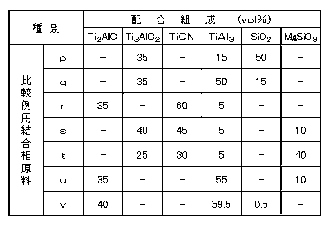
- a comparative sintered body was produced.
- the raw material powder as a hard raw material, a cBN raw material having an average particle size of 1.0 to 4.0 ⁇ m after sintering as shown in Table 4, and as a raw material powder constituting a binder phase, Ti 2 AlC or A raw material powder containing Ti 3 AlC 2 was prepared.
- the Ti 2 AlC and Ti 3 AlC 2 raw materials had an average particle size (D50) of 50 ⁇ m (the other powders had the same average particle size as in Examples). These were blended so as to have the compositions shown in Tables 1 and 3, and were mixed by a ball mill under the same conditions as in Examples.
- example sintered bodies 1 to 23 and comparative example sintered bodies 1 to 9 were prepared, mounted on an NC lathe, and subjected to the following wet cutting test.
- Cutting speed 150m/min Cutting depth: 0.3mm Feed rate: 0.1mm/rev Work Material: Granite (produced in Takine) Shape ⁇ 150mm ⁇ 200mmL
- Cutting oil material Water-soluble cutting oil (NEOCOOL manufactured by MORESCO Co., Ltd.) The amount of wear of the cutting edge and the state of the cutting edge were confirmed when the cutting length (cutting distance) was 800 m. However, the cutting edge was observed every 100 m of cutting length, and the presence or absence of chipping and the amount of wear were measured. If the amount of wear exceeded 2000 ⁇ m, the cutting test was stopped at that point. Table 5 shows the results.
Abstract
Description
このような状況の下で、超硬合金、cBN焼結体に対して、切削性能や掘削性能を改善するための提案がなされている。 Here, the excavating tool is a tool for digging and digging the ground or bedrock. On the other hand, rocks in the ground are not uniform in composition and strength, and are brittle materials. Therefore, unlike cutting, which emphasizes the performance of cutting and scraping, the drilling tool must withstand the impact and vibration to break the rock, and the rotation to efficiently remove the broken rock.
Under such circumstances, proposals have been made to improve the cutting performance and drilling performance of cemented carbide and cBN sintered bodies.
1)立方晶窒化硼素粒子と結合相を有し、
2)前記結合相は、Si、Mg、Znの1種以上を有するTi-Al合金の他に、Ti2CN、TiB2、AlN、Al2O3を含み、
3)XRDにおける2θが41.9°から42.2°に出現するTi2CNのピーク強度をITi2CNとし、同2θが39.0°から39.3°に出現するTi-Al合金のピーク強度をITiAlとするとき、前記ピーク強度の比、ITi2CN/ITiAlが2.0以上、30.0以下であり、
4)オージェ電子分光法によるTi、Al、Si、Mg、Znの各元素のマッピング像において、TiとAlの各元素が重なる箇所の平均面積STiAlに対するTiとAlおよびSi、Mg、Znの1種以上の元素が重なる箇所の平均面積STiAlMの比、STiAlM/STiAlが0.05以上、0.98以下である。 The cBN sintered body according to the embodiment of the present invention is
1) having cubic boron nitride particles and a binder phase,
2) the binder phase includes Ti—Al alloy containing one or more of Si, Mg, and Zn, as well as Ti 2 CN, TiB 2 , AlN, and Al 2 O 3 ;
3) The peak intensity of Ti 2 CN appearing at 2θ of 41.9° to 42.2° in XRD is defined as I Ti2CN , and the peak of Ti—Al alloy appearing at 2θ of 39.0° to 39.3°. When the intensity is I TiAl , the peak intensity ratio, I Ti2CN /I TiAl , is 2.0 or more and 30.0 or less,
4) In the mapping image of each element of Ti, Al, Si, Mg, and Zn by Auger electron spectroscopy, the average area S of the place where each element of Ti and Al overlaps 1 of Ti and Al and Si, Mg, and Zn with respect to TiAl The ratio S TiAlM /S TiAl of the average area S TiAlM of the portions where more than one element overlaps is 0.05 or more and 0.98 or less.
なお、本明細書、特許請求の範囲の記載において、数値範囲を「AからB」、「A~B」(A、Bは共に数値)と表現する場合、「A以上、B以下」と同義であって、その範囲は上限値(B)と下限値(A)を含むものである。また、上限値(B)のみに単位が記載されているとき、上限値(B)と下限値(A)の単位は同じである。 Below, the cBN sintered body according to the embodiment of the present invention will be described in detail, focusing on the case where it is applied to a drilling tool.
In the description of this specification and claims, when the numerical range is expressed as "A to B" or "A to B" (A and B are both numerical values), it is synonymous with "A or more and B or less". and the range includes the upper limit (B) and the lower limit (A). Moreover, when the unit is described only for the upper limit (B), the units for the upper limit (B) and the lower limit (A) are the same.
cBN粒子の平均粒径とcBN焼結体に占めるcBN粒子の含有量について説明する。 1. Cubic Boron Nitride (cBN) Particles The average particle size of cBN particles and the content of cBN particles in the cBN sintered body will be described.
本実施形態で用いるcBN粒子の平均粒径は、特に限定されるものではないが、0.5μm以上、30.0μm以下の範囲にあることがより好ましい。 (1) Average Particle Size The average particle size of the cBN particles used in the present embodiment is not particularly limited, but is preferably in the range of 0.5 μm or more and 30.0 μm or less.
cBN焼結体の断面を鏡面加工し、鏡面加工した面に対して走査型電子顕微鏡(Scanning Electron Microscope:以下、SEMという)による組織観察を実施し、二次電子像を得る。次に、得られた画像内のcBN粒子の部分を画像処理にて抜き出し、画像解析より求めた各粒子の最大長を基に、後述する平均粒径を算出する。 Here, the average particle diameter of cBN particles can be determined as follows.
The cross section of the cBN sintered body is mirror-finished, and the mirror-finished surface is subjected to structural observation with a scanning electron microscope (hereinafter referred to as SEM) to obtain a secondary electron image. Next, the cBN grain portion in the obtained image is extracted by image processing, and the average grain size, which will be described later, is calculated based on the maximum length of each grain determined by image analysis.
cBN焼結体に占めるcBN粒子の含有量(vol%)は、特に限定されるものではないが、65.0vol%以上、93.0vol%以下が好ましい。 (2) Content The content (vol%) of the cBN particles in the cBN sintered body is not particularly limited, but is preferably 65.0vol% or more and 93.0vol% or less.
本実施形態の結合相には、Si、Mg、Znの1種以上を有するTi-Al合金の他に、Ti2CN、TiB2、AlN、Al2O3が含まれることが好ましい。
ここで、Si、Mg、Znの1種以上とは、Si、Mg、Znのどれか1種、または、Si、Mg、Znのどれか2種、または、Si、Mg、Znの3種(全て)のいずれかをいう。 2. Binder Phase The binder phase of the present embodiment preferably contains Ti 2 CN, TiB 2 , AlN, Al 2 O 3 as well as a Ti—Al alloy having one or more of Si, Mg, and Zn.
Here, one or more of Si, Mg and Zn means any one of Si, Mg and Zn, or any two of Si, Mg and Zn, or three of Si, Mg and Zn ( all).
XRDにおける2θが41.9°から42.2°に出現するTi2CNのピーク強度をITi2CNとし、同2θが39.0°から39.3°に出現するTi-Al合金のピーク強度をITiAlとするとき、ピーク強度の比、ITi2CN/ITiAlが2.0以上、30.0以下であることが好ましい。ピーク強度の比がこの範囲にあるとき、耐摩耗性、耐アブレッシブ摩耗性に優れ、例えば、岩石掘削時の衝撃や振動による欠損などの損傷要因に対する耐性の高いcBN焼結体となる。 Then, when the XRD peak intensities of Ti 2 CN and the Ti—Al alloy contained in the binder phase have a predetermined relationship, that is,
The peak intensity of Ti 2 CN appearing at 2θ of 41.9° to 42.2° in XRD is defined as I Ti2CN , and the peak intensity of the Ti—Al alloy appearing at 2θ of 39.0° to 39.3° is When I TiAl , the peak intensity ratio, I Ti2CN /I TiAl , is preferably 2.0 or more and 30.0 or less. When the peak strength ratio is within this range, the cBN sintered body is excellent in wear resistance and abrasive wear resistance and, for example, highly resistant to damage factors such as chipping due to impact and vibration during rock excavation.
ここで、AESを使った観察領域は、例えば、15μm×15μm程度が好ましい。 In addition, one or more of Si, Mg, and Zn are dispersed together in the Ti--Al alloy in the binder phase, and are analyzed by Auger Electron Spectroscopy (AES). In the mapping image of each element of Zn, the average area S at which Ti and Al overlap The average area S at which Ti and Al and one or more elements of Si, Mg, and Zn overlap with respect to TiAl Ratio of TiAlM S TiAlM /S TiAl is preferably between 0.05 and 0.98.
Here, the observation area using AES is preferably about 15 μm×15 μm, for example.
(付記1)
立方晶窒化硼素粒子と結合相を有するcBN焼結体であって、
1)前記結合相は、Si、Mg、Znの1種以上を有するTi-Al合金の他に、Ti2CN、TiB2、AlN、Al2O3を含み、
2)XRDにおける2θが41.9°から42.2°に出現するTi2CNのピーク強度をITi2CNとし、同2θが39.0°から39.3°に出現するTi-Al合金のピーク強度をITiAlとするとき、前記ピーク強度の比、ITi2CN/ITiAlが2.0以上、30.0以下であり、
3)オージェ電子分光法によるTi、Al、Si、Mg、Znの各元素のマッピング像において、TiとAlの各元素が重なる箇所の平均面積STiAlに対するTiとAlおよびSi、Mg、Znの1種以上の元素が重なる箇所の平均面積STiAlMの比、STiAlM/STiAlが0.05以上、0.98以下である、
ことを特徴とするcBN焼結体。
(付記2)
前記立方晶窒化硼素粒子の平均粒径が0.5μm以上、30.0μm以下であることを特徴とする付記1に記載のcBN焼結体。
(付記3)
前記立方晶窒化硼素粒子の含有量が、65vol%以上、93.0vol%以下であることを特徴とする付記1または付記2に記載のcBN焼結体。 The above description includes the features appended below.
(Appendix 1)
A cBN sintered body having cubic boron nitride particles and a binder phase,
1) the binder phase includes Ti—Al alloy containing one or more of Si, Mg, and Zn, as well as Ti 2 CN, TiB 2 , AlN, and Al 2 O 3 ;
2) The peak intensity of Ti 2 CN appearing at 2θ of 41.9° to 42.2° in XRD is defined as I Ti2CN , and the peak of Ti—Al alloy appearing at 2θ of 39.0° to 39.3°. When the intensity is I TiAl , the peak intensity ratio, I Ti2CN /I TiAl , is 2.0 or more and 30.0 or less,
3) In the mapping image of each element of Ti, Al, Si, Mg, and Zn by Auger electron spectroscopy, the average area S at which each element of Ti and Al overlap Ti and Al and Si, Mg, and Zn relative to TiAl The ratio of the average area S TiAlM where more than one element overlaps, S TiAlM /S TiAl , is 0.05 or more and 0.98 or less.
A cBN sintered body characterized by:
(Appendix 2)
The cBN sintered body according to appendix 1, wherein the cubic boron nitride particles have an average particle size of 0.5 μm or more and 30.0 μm or less.
(Appendix 3)
The cBN sintered body according to appendix 1 or appendix 2, wherein the content of the cubic boron nitride particles is 65 vol% or more and 93.0 vol% or less.
硬質原料として、表2に示すように焼結後の平均粒径が0.5から35.0μmとなるようにcBN原料を、結合相を構成する原料粉末として、Ti2AlCおよびTi3AlC2原料を、それぞれ用意した。Ti2AlCおよびTi3AlC2原料は、共に平均粒径50μmであった。 (1) Preparation of raw material powder As a hard raw material, as shown in Table 2, cBN raw material having an average particle size after sintering of 0.5 to 35.0 μm, and as a raw material powder constituting a binder phase, Ti 2 AlC and Ti 3 AlC 2 sources were prepared respectively. Both the Ti 2 AlC and Ti 3 AlC 2 raw materials had an average particle size of 50 μm.
これら準備した粉末のうちSi、Mg、Zn元素を含む粉末以外の粉末を、超硬合金で内張りされたボールミル容器内に超硬合金製のボールとアセトンと共に充填して混合した。混合時間は原料粉を細かく粉砕させないように、1時間であった。本実施例では行っていないが、超音波攪拌装置を用いて原料粉の凝集を解砕しながら混合することがより好ましい。 (2) Mixing/temporary heat treatment Among the prepared powders, powders other than those containing Si, Mg, and Zn elements were filled in a ball mill container lined with cemented carbide together with balls made of cemented carbide and acetone. Mixed. The mixing time was 1 hour so as not to pulverize the raw material powder. Although not performed in this example, it is more preferable to mix the raw material powders while crushing agglomerates using an ultrasonic stirrer.
次いで、得られた焼結体原料粉末から成形体を作製し、その後、超高圧高温焼結装置に装入して、圧力:5GPa、温度:1600℃で焼結することにより、表2に示す本発明のcBN焼結体(実施例焼結体という)1~23を作製した。表2の各値は、前記した方法により測定したものである。ここで、cBN粒子の平均粒径や含有割合は、cBN粒子が観察領域の中に少なくとも30個以上観察される観察領域を用い、その他の観察領域は、例示した大きさを用いて測定した。 (3) Molding and sintering Next, a molded body is produced from the obtained sintered raw material powder, and then placed in an ultra-high pressure and high temperature sintering apparatus and sintered at a pressure of 5 GPa and a temperature of 1600 ° C. Thus, cBN sintered bodies (referred to as example sintered bodies) 1 to 23 of the present invention shown in Table 2 were produced. Each value in Table 2 was measured by the method described above. Here, the average particle size and content ratio of the cBN particles were measured using an observation area where at least 30 cBN particles were observed in the observation area, and using the exemplified sizes for the other observation areas.


切込量:0.3mm
送り量:0.1mm/rev
被削材:花崗岩(滝根産) 形状Φ150mm×200mmL
切削油材:水溶性切削油(株式会社MORESCO製ネオクール)
切削長(切削距離)が800mのときの刃先の摩耗量と刃先の状態を確認した。ただし、切削長が100m毎に刃先を観察し、欠損の有無、摩耗量を測定し、摩耗量が2000μmを超えていればその時点で切削試験を中止した。結果を表5に示す。 Cutting speed: 150m/min
Cutting depth: 0.3mm
Feed rate: 0.1mm/rev
Work Material: Granite (produced in Takine) Shape Φ150mm×200mmL
Cutting oil material: Water-soluble cutting oil (NEOCOOL manufactured by MORESCO Co., Ltd.)
The amount of wear of the cutting edge and the state of the cutting edge were confirmed when the cutting length (cutting distance) was 800 m. However, the cutting edge was observed every 100 m of cutting length, and the presence or absence of chipping and the amount of wear were measured. If the amount of wear exceeded 2000 μm, the cutting test was stopped at that point. Table 5 shows the results.

The disclosed embodiments are merely illustrative in all respects and are not restrictive. The scope of the present invention is indicated by the scope of the claims rather than the above-described embodiments, and is intended to include meanings equivalent to the scope of the claims and all modifications within the scope.
Claims (1)
- 立方晶窒化硼素と結合相を有するcBN焼結体であって、
1)前記結合相は、Si、Mg、Znの1種以上を有するTi-Al合金の他に、Ti2CN、TiB2、AlN、Al2O3を含み、
2)XRDにおける2θが41.9°から42.2°に出現するTi2CNのピーク強度をITi2CNとし、同2θが39.0°から39.3°に出現するTi-Al合金のピーク強度をITiAlとするとき、前記ピーク強度の比、ITi2CN/ITiAlが2.0以上、30.0以下であり、
3)オージェ電子分光法によるTi、Al、Si、Mg、Znの各元素のマッピング像において、TiとAlの各元素が重なる箇所の平均面積STiAlに対するTiとAlおよびSi、Mg、Znの1種以上の元素が重なる箇所の平均面積STiAlMの比、STiAlM/STiAlが0.05以上、0.98以下である、
ことを特徴とするcBN焼結体。 A cBN sintered body having cubic boron nitride and a binder phase,
1) the binder phase includes Ti—Al alloy containing one or more of Si, Mg, and Zn, as well as Ti 2 CN, TiB 2 , AlN, and Al 2 O 3 ;
2) The peak intensity of Ti 2 CN appearing at 2θ of 41.9° to 42.2° in XRD is defined as I Ti2CN , and the peak of Ti—Al alloy appearing at 2θ of 39.0° to 39.3°. When the intensity is I TiAl , the peak intensity ratio, I Ti2CN /I TiAl , is 2.0 or more and 30.0 or less,
3) In the mapping image of each element of Ti, Al, Si, Mg, and Zn by Auger electron spectroscopy, the average area S at which each element of Ti and Al overlap Ti and Al and Si, Mg, and Zn relative to TiAl The ratio of the average area S TiAlM where more than one element overlaps, S TiAlM /S TiAl , is 0.05 or more and 0.98 or less.
A cBN sintered body characterized by:
Priority Applications (3)
| Application Number | Priority Date | Filing Date | Title |
|---|---|---|---|
| US18/263,245 US20240102135A1 (en) | 2021-01-30 | 2022-01-24 | cBN SINTERED COMPACT |
| JP2022578360A JPWO2022163572A1 (en) | 2021-01-30 | 2022-01-24 | |
| EP22745793.4A EP4286554A1 (en) | 2021-01-30 | 2022-01-24 | Cbn sintered compact |
Applications Claiming Priority (2)
| Application Number | Priority Date | Filing Date | Title |
|---|---|---|---|
| JP2021014037 | 2021-01-30 | ||
| JP2021-014037 | 2021-01-30 |
Publications (1)
| Publication Number | Publication Date |
|---|---|
| WO2022163572A1 true WO2022163572A1 (en) | 2022-08-04 |
Family
ID=82653519
Family Applications (1)
| Application Number | Title | Priority Date | Filing Date |
|---|---|---|---|
| PCT/JP2022/002411 WO2022163572A1 (en) | 2021-01-30 | 2022-01-24 | Cbn sintered compact |
Country Status (4)
| Country | Link |
|---|---|
| US (1) | US20240102135A1 (en) |
| EP (1) | EP4286554A1 (en) |
| JP (1) | JPWO2022163572A1 (en) |
| WO (1) | WO2022163572A1 (en) |
Citations (10)
| Publication number | Priority date | Publication date | Assignee | Title |
|---|---|---|---|---|
| JPS5389809A (en) | 1977-01-19 | 1978-08-08 | Mitsubishi Metal Corp | Superhard alloy for bit |
| JPS56156738A (en) * | 1981-03-16 | 1981-12-03 | Sumitomo Electric Ind Ltd | Sintered body for high hardness tool and its manufacture |
| JPS61146763A (en) * | 1984-12-17 | 1986-07-04 | 三菱マテリアル株式会社 | Manufacture of sintered body for cutting tool |
| JPS61201751A (en) * | 1985-03-04 | 1986-09-06 | Nippon Oil & Fats Co Ltd | High hardness sintered body and its manufacture |
| JPH05310474A (en) | 1991-04-23 | 1993-11-22 | Toshiba Tungaloy Co Ltd | High-toughness boron nitride sintered compact with high-pressure phase |
| JPH07172919A (en) * | 1993-12-21 | 1995-07-11 | Kyocera Corp | Titanium-compound sintered material |
| JP2007039329A (en) * | 2005-08-03 | 2007-02-15 | Smith Internatl Inc | High content cbn-containing material, compact incorporating the same and method of making the same |
| JP2008517868A (en) * | 2004-10-29 | 2008-05-29 | エレメント シックス (プロダクション)(プロプライエタリィ) リミテッド | Cubic boron nitride compact |
| JP2013537116A (en) | 2010-09-08 | 2013-09-30 | エレメント シックス リミテッド | Solid PCBN compact with high CBN content enabling EDM cutting |
| JP2021014037A (en) | 2019-07-10 | 2021-02-12 | 京セラドキュメントソリューションズ株式会社 | Optical scanner and image formation apparatus provided with the same |
-
2022
- 2022-01-24 JP JP2022578360A patent/JPWO2022163572A1/ja active Pending
- 2022-01-24 EP EP22745793.4A patent/EP4286554A1/en active Pending
- 2022-01-24 WO PCT/JP2022/002411 patent/WO2022163572A1/en active Application Filing
- 2022-01-24 US US18/263,245 patent/US20240102135A1/en active Pending
Patent Citations (10)
| Publication number | Priority date | Publication date | Assignee | Title |
|---|---|---|---|---|
| JPS5389809A (en) | 1977-01-19 | 1978-08-08 | Mitsubishi Metal Corp | Superhard alloy for bit |
| JPS56156738A (en) * | 1981-03-16 | 1981-12-03 | Sumitomo Electric Ind Ltd | Sintered body for high hardness tool and its manufacture |
| JPS61146763A (en) * | 1984-12-17 | 1986-07-04 | 三菱マテリアル株式会社 | Manufacture of sintered body for cutting tool |
| JPS61201751A (en) * | 1985-03-04 | 1986-09-06 | Nippon Oil & Fats Co Ltd | High hardness sintered body and its manufacture |
| JPH05310474A (en) | 1991-04-23 | 1993-11-22 | Toshiba Tungaloy Co Ltd | High-toughness boron nitride sintered compact with high-pressure phase |
| JPH07172919A (en) * | 1993-12-21 | 1995-07-11 | Kyocera Corp | Titanium-compound sintered material |
| JP2008517868A (en) * | 2004-10-29 | 2008-05-29 | エレメント シックス (プロダクション)(プロプライエタリィ) リミテッド | Cubic boron nitride compact |
| JP2007039329A (en) * | 2005-08-03 | 2007-02-15 | Smith Internatl Inc | High content cbn-containing material, compact incorporating the same and method of making the same |
| JP2013537116A (en) | 2010-09-08 | 2013-09-30 | エレメント シックス リミテッド | Solid PCBN compact with high CBN content enabling EDM cutting |
| JP2021014037A (en) | 2019-07-10 | 2021-02-12 | 京セラドキュメントソリューションズ株式会社 | Optical scanner and image formation apparatus provided with the same |
Also Published As
| Publication number | Publication date |
|---|---|
| EP4286554A1 (en) | 2023-12-06 |
| JPWO2022163572A1 (en) | 2022-08-04 |
| US20240102135A1 (en) | 2024-03-28 |
Similar Documents
| Publication | Publication Date | Title |
|---|---|---|
| US10584069B2 (en) | cBN sintered material and cutting tool | |
| JP5499718B2 (en) | Sintered body and cutting tool using the sintered body | |
| WO2022168655A1 (en) | Sintered cbn | |
| WO2021182462A1 (en) | Hard composite material | |
| WO2022163572A1 (en) | Cbn sintered compact | |
| WO2021182463A1 (en) | Hard composite material | |
| WO2022176569A1 (en) | Cbn sintered body | |
| CN111801304B (en) | cBN sintered body and cutting tool | |
| WO2022210760A1 (en) | Drilling tip and drilling tool | |
| US20240132411A1 (en) | cBN SINTERED BODY | |
| JP2011140414A (en) | Sintered compact and cutting tool using the sintered compact | |
| JP2021143105A (en) | Hard composite material | |
| JP7377463B2 (en) | cBN sintered body and cutting tools | |
| WO2020179809A1 (en) | cBN SINTERED COMPACT AND CUTTING TOOL | |
| JP2021143106A (en) | Hard composite material | |
| JP2020050559A (en) | cBN sintered body and cutting tool | |
| WO2022210771A1 (en) | Drilling tip and drilling tool | |
| JP6933017B2 (en) | Cubic boron nitride base sintered body and cutting tool | |
| JP7137119B2 (en) | cBN sintered body and cutting tool | |
| JP2022142894A (en) | cBN SINTERED COMPACT | |
| JP2022147104A (en) | cBN SINTERED BODY AND CUTTING TOOL INCLUDING THE SAME | |
| JP2014111542A (en) | Sintered compact, and cutting tool using the sintered compact |
Legal Events
| Date | Code | Title | Description |
|---|---|---|---|
| 121 | Ep: the epo has been informed by wipo that ep was designated in this application |
Ref document number: 22745793 Country of ref document: EP Kind code of ref document: A1 |
|
| ENP | Entry into the national phase |
Ref document number: 2022578360 Country of ref document: JP Kind code of ref document: A |
|
| WWE | Wipo information: entry into national phase |
Ref document number: 18263245 Country of ref document: US |
|
| WWE | Wipo information: entry into national phase |
Ref document number: 2022745793 Country of ref document: EP |
|
| NENP | Non-entry into the national phase |
Ref country code: DE |
|
| ENP | Entry into the national phase |
Ref document number: 2022745793 Country of ref document: EP Effective date: 20230830 |