WO2022158505A1 - ウイルス濃縮用材料 - Google Patents
ウイルス濃縮用材料 Download PDFInfo
- Publication number
- WO2022158505A1 WO2022158505A1 PCT/JP2022/001883 JP2022001883W WO2022158505A1 WO 2022158505 A1 WO2022158505 A1 WO 2022158505A1 JP 2022001883 W JP2022001883 W JP 2022001883W WO 2022158505 A1 WO2022158505 A1 WO 2022158505A1
- Authority
- WO
- WIPO (PCT)
- Prior art keywords
- virus
- fiber
- fiber assembly
- antibody
- fibers
- Prior art date
- Legal status (The legal status is an assumption and is not a legal conclusion. Google has not performed a legal analysis and makes no representation as to the accuracy of the status listed.)
- Ceased
Links
Images







Classifications
-
- C—CHEMISTRY; METALLURGY
- C07—ORGANIC CHEMISTRY
- C07K—PEPTIDES
- C07K16/00—Immunoglobulins [IG], e.g. monoclonal or polyclonal antibodies
- C07K16/08—Immunoglobulins [IG], e.g. monoclonal or polyclonal antibodies against material from viruses
-
- C—CHEMISTRY; METALLURGY
- C07—ORGANIC CHEMISTRY
- C07K—PEPTIDES
- C07K19/00—Hybrid peptides, i.e. peptides covalently bound to nucleic acids, or non-covalently bound protein-protein complexes
-
- C—CHEMISTRY; METALLURGY
- C12—BIOCHEMISTRY; BEER; SPIRITS; WINE; VINEGAR; MICROBIOLOGY; ENZYMOLOGY; MUTATION OR GENETIC ENGINEERING
- C12N—MICROORGANISMS OR ENZYMES; COMPOSITIONS THEREOF; PROPAGATING, PRESERVING, OR MAINTAINING MICROORGANISMS; MUTATION OR GENETIC ENGINEERING; CULTURE MEDIA
- C12N15/00—Mutation or genetic engineering; DNA or RNA concerning genetic engineering, vectors, e.g. plasmids, or their isolation, preparation or purification; Use of hosts therefor
- C12N15/09—Recombinant DNA-technology
-
- C—CHEMISTRY; METALLURGY
- C12—BIOCHEMISTRY; BEER; SPIRITS; WINE; VINEGAR; MICROBIOLOGY; ENZYMOLOGY; MUTATION OR GENETIC ENGINEERING
- C12N—MICROORGANISMS OR ENZYMES; COMPOSITIONS THEREOF; PROPAGATING, PRESERVING, OR MAINTAINING MICROORGANISMS; MUTATION OR GENETIC ENGINEERING; CULTURE MEDIA
- C12N7/00—Viruses; Bacteriophages; Compositions thereof; Preparation or purification thereof
- C12N7/02—Recovery or purification
-
- C—CHEMISTRY; METALLURGY
- C12—BIOCHEMISTRY; BEER; SPIRITS; WINE; VINEGAR; MICROBIOLOGY; ENZYMOLOGY; MUTATION OR GENETIC ENGINEERING
- C12Q—MEASURING OR TESTING PROCESSES INVOLVING ENZYMES, NUCLEIC ACIDS OR MICROORGANISMS; COMPOSITIONS OR TEST PAPERS THEREFOR; PROCESSES OF PREPARING SUCH COMPOSITIONS; CONDITION-RESPONSIVE CONTROL IN MICROBIOLOGICAL OR ENZYMOLOGICAL PROCESSES
- C12Q1/00—Measuring or testing processes involving enzymes, nucleic acids or microorganisms; Compositions therefor; Processes of preparing such compositions
- C12Q1/70—Measuring or testing processes involving enzymes, nucleic acids or microorganisms; Compositions therefor; Processes of preparing such compositions involving virus or bacteriophage
-
- G—PHYSICS
- G01—MEASURING; TESTING
- G01N—INVESTIGATING OR ANALYSING MATERIALS BY DETERMINING THEIR CHEMICAL OR PHYSICAL PROPERTIES
- G01N33/00—Investigating or analysing materials by specific methods not covered by groups G01N1/00 - G01N31/00
- G01N33/48—Biological material, e.g. blood, urine; Haemocytometers
- G01N33/50—Chemical analysis of biological material, e.g. blood, urine; Testing involving biospecific ligand binding methods; Immunological testing
- G01N33/53—Immunoassay; Biospecific binding assay; Materials therefor
- G01N33/543—Immunoassay; Biospecific binding assay; Materials therefor with an insoluble carrier for immobilising immunochemicals
-
- G—PHYSICS
- G01—MEASURING; TESTING
- G01N—INVESTIGATING OR ANALYSING MATERIALS BY DETERMINING THEIR CHEMICAL OR PHYSICAL PROPERTIES
- G01N33/00—Investigating or analysing materials by specific methods not covered by groups G01N1/00 - G01N31/00
- G01N33/48—Biological material, e.g. blood, urine; Haemocytometers
- G01N33/50—Chemical analysis of biological material, e.g. blood, urine; Testing involving biospecific ligand binding methods; Immunological testing
- G01N33/53—Immunoassay; Biospecific binding assay; Materials therefor
- G01N33/569—Immunoassay; Biospecific binding assay; Materials therefor for microorganisms, e.g. protozoa, bacteria, viruses
Definitions
- the present invention relates to a virus concentration material capable of concentrating viruses in a fluid to be tested, a method for producing the same, a virus concentration kit, a virus test kit, a virus concentration method, and a virus test method using the same.
- Viral tests that can determine the presence or absence of infection include genetic tests that detect viral genes (nucleic acids) from specimens, and antigen tests that detect virus-specific proteins from specimens using virus-specific antibodies. mentioned.
- Patent Document 1 Japanese Unexamined Patent Application Publication No. 2002-78485 describes a virus concentration material having antibodies against a target virus on its surface.
- a virus concentration material is a fiber assembly having fibers; an antibody against the target virus carried on the surface of the fiber; Prepare.
- the median fiber diameter of said fibers is less than 20 ⁇ m.
- the surface of said fibers is modified with one or more anionic or cationic polymers having amphiphilic properties.
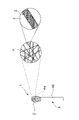
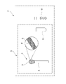
- FIG. 1 is a schematic front view showing a virus concentration material according to an embodiment of the present invention and an enlarged view enlarging a part thereof.
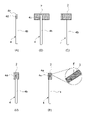
- FIG. FIG. 2 shows a virus concentration material according to another embodiment of the present invention, wherein (A) to (D) show the manufacturing process of the virus concentration material, and (E) shows the virus concentration material. It is an enlarged view which expands a front view and a part of it.
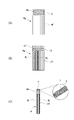
- FIG. 2 shows a virus concentration material according to another embodiment of the present invention, where (A) and (B) show the manufacturing process of the virus concentration material, and (C) shows the virus concentration material. It is an enlarged view which expands a front view and a part of it.
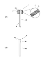
- FIG. 3 is a schematic perspective view showing a virus concentration material according to another embodiment of the present invention and an enlarged view enlarging a part thereof.
- FIG. 3 is a schematic front view showing a virus concentration material according to another embodiment of the present invention and an enlarged view enlarging a part thereof.
- FIG. 2 is a schematic diagram for explaining the virus concentration principle using the virus concentration material of the present invention.
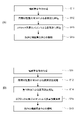
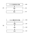
- (A) is a flow chart showing a method for producing a material for virus concentration according to one embodiment of the present invention
- (B) is a flow chart showing a method for producing a material for virus concentration according to another embodiment.
- (A) and (B) are each a flowchart showing a method for producing a virus concentration material according to another embodiment of the present invention.
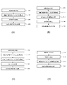
- (A) to (D) are each a flow diagram showing a method for producing a virus concentration material according to another embodiment of the present invention.
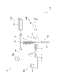
- 1 is a schematic diagram showing a fiber manufacturing apparatus used for manufacturing a virus concentration material according to an embodiment of the present invention
- FIG. 1 is a schematic diagram showing a virus concentration kit and a virus test kit containing virus concentration materials according to one embodiment of the present invention.
- FIG. 4 is a schematic diagram showing a virus concentration kit and a virus test kit containing virus concentration materials according to another embodiment of the present invention.
- (A) is a flow chart showing a virus concentration method according to one embodiment of the present invention
- (B) and (C) are flow charts showing virus concentration methods according to other embodiments, respectively.
- (A) is a flow diagram showing a virus inspection method according to one embodiment of the present invention
- (B) is a flow diagram showing a virus inspection method according to another embodiment.
- 1 is a graph showing the results of Test Example 1 of the present invention, showing the results of detection by ELISA of the amount of S1 protein in the supernatant of the S1 protein dispersion of SARS-CoV-2 brought into contact with samples i to iv. graph.
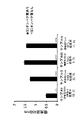
- FIG. 10 is a graph showing the results of Test Example 2 of the present invention, and showing the results of detection by ELISA of the S1 protein amount of SARS-CoV-2 adsorbed to the fiber assembly sample carrying each VHH antibody.
- FIG. In the graph the horizontal axis indicates each sample, and the vertical axis indicates the absorbance.
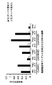
- FIG. 4 is a graph showing the results of Test Example 3 of the present invention, in which the amount of VHH antibody supported per 1 g of each fiber assembly sample was measured by SDS-PAGE, and the band intensity was quantified. be.
- the horizontal axis indicates each sample, and the vertical axis indicates band intensity.
- FIG. 4 is a flow chart showing manufacturing steps of Samples 1 to 4 of the antibody-supporting fiber assembly produced in Test Example 4 of the present invention, and a diagram showing materials used in each step.
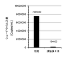
- FIG. 10 is a graph showing the results of Test Example 6 of the present invention, showing the results of quantification by ddPCR of the amount of SARS-CoV-2 pseudovirus before and after contact with the virus concentration material.
- FIG. In the graph the horizontal axis indicates each sample, and the vertical axis indicates the gene copy number in the SARS-CoV-2 pseudovirus.
- FIG. 10 is a graph showing the results of Test Example 7 of the present invention, and showing the adsorption rate of SARS-CoV-2 pseudovirus to the virus concentration material under each test condition.
- FIG. 10 is a graph showing the results of Test Example 8 of the present invention, and is a graph plotting the band intensity values of the recombinant N protein obtained by Western blotting and the amount of the recombinant N protein.
- FIG. In the graph the horizontal axis indicates the amount of N protein, the vertical axis indicates the band intensity value, and the formula in the graph indicates a linear approximate curve of three points. Fig.
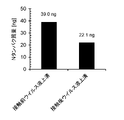
- FIG. 10 is a graph showing the results of Test Example 8 of the present invention, showing the results of detecting the amount of N protein derived from the novel coronavirus before and after contact with the virus concentration material by Western blotting.
- the horizontal axis indicates each sample, and the vertical axis indicates the amount of N protein.
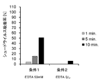
- FIG. 10 is a graph showing the results of Test Example 9 of the present invention, and showing the adsorption rate of SARS-CoV-2 pseudovirus in saliva samples with different EDTA concentrations to virus concentration materials.
- the horizontal axis indicates each sample, and the vertical axis indicates the SARS-CoV-2 pseudovirus adsorption rate.
- the present invention provides a virus concentration material that can easily concentrate viruses and increase detection sensitivity, a method for producing the same, a virus concentration kit, a virus test kit, a virus concentration method, and a virus test method using the same. Regarding.
- the virus concentration material of the present invention is a material capable of easily concentrating a target virus in a liquid to be tested for virus testing and increasing detection sensitivity.
- the virus test of the present invention includes antigen test and genetic test.
- An antigen test is a test that detects proteins or protein fragments of viruses.
- a genetic test is a test that detects the gene (nucleic acid) of a virus.
- virus inspection is also simply referred to as "inspection”.
- target virus is also simply referred to as "virus”.
- the "fluid to be tested” in the present invention is a liquid to be tested for viruses, and means a liquid specimen or a liquid containing a specimen collected from a test subject.
- concentration is an operation for generating a virus-containing liquid having a higher virus concentration from a test liquid. Specifically, the virus in the test liquid is added to the virus concentration material of the present invention. It means the operation of aggregating and adsorbing.
- concentration ratio means the ratio of the virus concentration in the virus-containing fluid after concentration to the virus concentration in the test fluid.
- a virus concentration material 1 comprises a fiber assembly 2 having fibers F and antibodies 3 against target viruses carried on the surfaces of the fibers F.
- a fiber assembly 2 having fibers F and antibodies 3 against target viruses carried on the surfaces of the fibers F.
- the antibodies 3 are densely arranged on the surface of the fiber F, as shown in the enlarged view of FIG.
- FIG. 1 shows an example in which the virus concentration material 1 has a swab-like configuration, but is not limited to this as will be described later.
- the fiber aggregate 2 is an aggregate of fibers F and is capable of maintaining a certain shape. From the viewpoint of facilitating molding, the fiber assembly 2 preferably has a cotton-like or sheet-like shape in which the fibers F are aggregated. When the fiber assembly 2 is flocculent, the fiber assembly 2 is selected from, for example, spheres, ellipsoids or similar shapes, polyhedrons or similar shapes, cones or similar shapes, or other shapes. has any shape. The fiber assembly 2 may have a structure in which two or more of these shapes are combined.
- the fiber assembly 2 is in the form of a sheet, for example, it is composed of a nonwoven fabric, a woven fabric, a knitted fabric, or a laminate thereof, and from the viewpoint of increasing the specific surface area of the fiber assembly 2, which will be described later, is preferably a nonwoven fabric or a laminate thereof.
- the sheet-like fiber assembly 2 has an arbitrary planar shape selected from, for example, circular, elliptical or similar shapes, polygonal or similar shapes, or other shapes.
- the sheet-like fiber assembly 2 may be used in a spread state, or may be used in a deformed state by folding or the like.
- the size of the fiber assembly 2 can be appropriately set in consideration of the amount of the liquid to be inspected, the capacity of the container containing the liquid to be inspected, and the like.
- the length of the longest portion of the fiber assembly 2 is preferably 1 mm or more, more preferably 3 mm or more, and preferably 20 mm or less, more preferably 30 mm or less.
- the length of the longest portion of the fiber assembly 2 is preferably 1 mm or more, more preferably 5 mm or more, and preferably 30 mm or less, more preferably 20 mm or less.
- the mass of the fiber assembly 2 is preferably 0.1 mg or more, more preferably 1 mg or more, and preferably 30 mg or less, more preferably 10 mg or less.
- the fiber assembly 2 is formed of fibers F having a very small fiber diameter from the viewpoint of carrying many antibodies 3 on the surface of the fibers F and being able to adsorb many viruses.
- the median fiber diameter of the fibers F is less than 20 ⁇ m. This increases the specific surface area of the fiber assembly 2, which will be described later, and increases the amount of the antibody 3 that can be supported on the fiber assembly 2 per unit mass. More specifically, the median fiber diameter of the fiber F is preferably 2 ⁇ m or less, more preferably 1 ⁇ m or less, from the viewpoint of obtaining a sufficient specific surface area and being able to adsorb more viruses with a small amount of fiber aggregates. It is preferably 0.8 ⁇ m or less.
- the median fiber diameter of the fiber F increases the strength of the fiber assembly 2 and maintains the structure of the fiber assembly 2, thereby maintaining a high volume and surface area of the pore structure of the fiber assembly 2, and increasing the number of viruses.
- the particle size is preferably 0.01 ⁇ m or more, more preferably 0.05 ⁇ m or more, and still more preferably 0.1 ⁇ m or more.
- the "fiber diameter" of the present invention means a circle-equivalent diameter, and the "median fiber diameter” means a fiber diameter calculated by the following method.
- 500 fibers are arbitrarily selected from a two-dimensional image observed with a scanning electron microscope (SEM), excluding defects such as fiber clumps, fiber intersections, and polymer droplets. It can be measured by directly reading the length when a line perpendicular to is drawn as the fiber diameter. The median fiber diameter can be obtained from the distribution of the measured fiber diameters of 500 fibers.
- SEM scanning electron microscope
- the fibers F of the present invention preferably have a highly uniform fiber diameter.
- the fiber diameter dispersion value of the fibers F contained in the fiber assembly 2 is preferably 0.5 or more, more preferably 1 or more, and preferably 2.5 or less, more preferably 2 or less. is.
- the specific surface area of the fiber F is preferably 1 m 2 /g or more, preferably 1.5 m 2 /g or more, and more preferably 2 m 2 /g or more, from the viewpoint of allowing more antibodies 3 to be supported on the surface.
- the specific surface area of the fiber F is preferably 50 m 2 /g or less, preferably 30 m 2 /g or less, more preferably 10 m 2 /g or less, from the viewpoint of obtaining a configuration that facilitates carrying the antibody 3 on the surface.
- the specific surface area of the fiber F means the surface area per unit mass of the fiber assembly 2 calculated from the pore volume with a pore diameter of 0.1 ⁇ m to 100 ⁇ m.
- the surface of the fiber F per unit mass that is, the area capable of supporting the antibody 3 is increased.
- more antibodies 3 are supported on the fiber assembly 2 per unit mass, and the virus adsorption amount of the fiber assembly 2 is considered to be improved. Therefore, by concentrating the test liquid using the fiber assembly 2, more viruses are collected in the fiber assembly 2, and the virus concentration rate is improved as described later.
- the specific surface area of the fiber F can be measured by the following method according to the mercury intrusion method specified in JIS R 1655. Specifically, a 0.02 g fiber assembly is cut out from the object to be measured as a measurement sample. The measurement cell containing the measurement sample was set in a mercury porosimeter (Autopore IV9500, manufactured by Micromeritics), and the measurement environment was 22° C., 65% RH, surface tension of mercury ⁇ : 480 dyn/cm, contact angle ⁇ : 140.
- a mercury porosimeter Autopore IV9500, manufactured by Micromeritics
- the cumulative pore size of the measurement sample when the mercury injection pressure P is increased within a predetermined range Measure the volume V (mL/g). Then, the converted pore diameter D ( ⁇ m) converted according to the following formula (2) is plotted on the horizontal axis, and the relationship with the log differential pore volume (dV / d (log D); mL / g) is plotted on the vertical axis, Obtain the pore volume distribution.
- the pore volume distribution is obtained by plotting the converted pore diameter D on the horizontal axis and the pore volume obtained by differentiating the accumulated pore volume V by the logarithm of the pore diameter D on the vertical axis.
- D 4 ⁇ cos ⁇ /P (2) ( ⁇ : surface tension of mercury, ⁇ : contact angle, P: mercury injection pressure)
- the pore shape at the converted pore diameter is cylindrically approximated to obtain the surface area, and the integral value of the surface area for each converted pore diameter is the weight of the measured sample.
- the value obtained by dividing is the specific surface area.
- the fiber assembly 2 preferably contains a resin capable of forming the fiber F or a natural fiber such as cellulose as a base material of the fiber F, and more preferably contains a resin. is more preferable.
- the synthetic resin includes one or more selected from thermoplastic resins and other resins. Examples of thermoplastic resins include polyolefin-based resins, polyester-based resins, polyamide-based resins, vinyl-based resins, acrylic-based resins, polyimide-based resins, aromatic polyetherketone-based resins, and polycarbonate resins. These resins can be used singly or in combination of two or more.
- Polyolefin resins include polypropylene, polyethylene, ethylene- ⁇ -olefin copolymers, ethylene-propylene copolymers, and the like.
- Polyester-based resins include polyethylene terephthalate, polytetramethylene tephthalate, polybutylene tephthalate, polyethylene naphthalate, polybutylene naphthalate, polyhydroxybutyric acid, polyhydroxyalkanoate, polycaprolactone, polybutylene succinate, polylactic acid and Polylactic acid-based resins such as lactic acid-hydroxycarboxylic acid copolymers, polybutylene naphthalate, liquid crystal polymers and the like are included.
- Polyamide-based resins include nylon 6, nylon 66, aramid, and the like.
- Vinyl resins include polyvinyl chloride resin, polyvinylidene chloride resin, vinyl acetate resin, vinylidene chloride resin, polyvinyl alcohol, polyvinyl acetal, polyvinyl butyral, and the like.
- acrylic resins include polyacrylic acid, polymethacrylic acid resin, polyacrylic acid ester, polymethacrylic acid and polymethacrylic acid ester.
- Polyimide resins include polyimide resins, polyamideimide resins, polyetherimide resins, and the like.
- aromatic polyetherketone-based resins include polyetherketone, polyetheretherketone, polyetheretherketoneketone, and the like.
- nitrile resins include polyacrylonitrile resins.
- the fiber assembly 2 may contain polymer compounds capable of forming fibers, which are listed in paragraphs 0040 to 0042 of JP-A-2020-90097. By including the thermoplastic resin in the fiber assembly 2, there is an effect that adhesion and shaping can be achieved by heat fusion without using a binder or the like.
- the fiber assembly 2 preferably contains a thermoplastic resin as a base material of the fibers F from the viewpoint of making the fibers F thinner than natural fibers. Furthermore, it is preferable to form the fiber assembly 2 by a melt electrospinning method using a thermoplastic resin, since the diameter can be further reduced.
- Melt electrospinning is a method in which a melt containing resin, which is the raw material of fibers, is discharged into an electric field while a high voltage is applied. is a method that can form The details of the melt electrospinning method will be described later.
- a thermoplastic resin as the raw material of the fiber assembly 2
- a melt containing the resin is generated by heating, and the fibers F having a reduced diameter can be formed using the melt electrospinning method.
- the content of the thermoplastic resin in the resin composition can be measured by the following method. Specifically, the resin composition is subjected to various analyzes such as NMR (nuclear magnetic resonance) analysis and IR (infrared spectroscopy) analysis, and based on the position of each signal and spectrum obtained by these analyzes, the molecular skeleton Identify the structure of and the terminal functional group structure of the molecular structure. Thereby, the type of resin contained is identified, and the amount of thermoplastic resin contained in each resin component is calculated from the intensity of the measured value indicating the molecular structure corresponding to each thermoplastic resin. By totaling the calculated values, the content of the thermoplastic resin contained in the resin composition can be measured.
- analyzes such as NMR (nuclear magnetic resonance) analysis and IR (infrared spectroscopy) analysis
- the content of the thermoplastic resin with respect to the total mass of the fiber assembly 2 is preferably 80% by mass or more, more preferably, from the viewpoint of stably performing the melt electrospinning method. is 90% by mass or more, more preferably 93% by mass or more.
- the content of the thermoplastic resin with respect to the total mass of the fiber assembly 2 is preferably 100% by mass. Below, more preferably 99 mass % or less, still more preferably 97 mass % or less.
- the fiber assembly 2 preferably contains a resin having a melting point as the base material of the fibers F, and more preferably contains a polyolefin resin.
- a polyolefin resin is a resin having a melting point.
- a resin that "has a melting point" means that when the resin to be measured is heated in the differential scanning calorimetry (DSC method), the phase changes from solid to liquid before the resin thermally decomposes. It is a resin that exhibits an endothermic peak due to
- the weight average molecular weight of the polyolefin resin is preferably 10,000 or more, more preferably 40,000 or more, and preferably 150,000 or less, more preferably 100,000 or less.
- the weight average molecular weight is determined, for example, using a high temperature size exclusion chromatography (high temperature SEC) method or a high temperature gel permeation chromatography (high temperature GPC) method described in JP-A-2014-129614, and the weight average molecular weight is known and Polystyrene standard samples with different weight average molecular weights (for example, monodisperse polystyrene manufactured by Tosoh Corporation (model numbers: F450, F288, F128, F80, F40, F20, F10, F4, F1, A5000, A2500, A1000, A500 and A300 )) is subjected to the high temperature SEC method or the high temperature GPC method to prepare a molecular weight calibration curve in advance, and the results of the measurement sample are compared with the calibration curve.
- high temperature SEC high temperature size exclusion chromatography
- GPC high temperature gel permeation chromatography
- ortho-dichlorobenzene is used as the eluent for the polyolefin resin, and the solution of the polypropylene resin is dissolved at a dissolution temperature of 140 to 150°C.
- polyolefin resins examples include polyethylene resins, polypropylene resins, ethylene- ⁇ -olefin copolymer resins, ethylene-propylene copolymers, and the like. These resins can be used singly or in combination of two or more.
- the fiber assembly 2 more preferably contains polypropylene resin as the base material of the fibers F. Thereby, the fibers F can be efficiently formed by the melt electrospinning method.
- the fiber assembly 2 preferably contains, as an additive for the fibers F, one or more selected from component (D) and component (E) below.
- a finer fiber F can be formed using, for example, a melt electrospinning method.
- additive for the fiber F means an additive added to the resin composition, which is the raw material of the fiber F, rather than a material that modifies the surface of the fiber F.
- Anionic surfactant (E) One or more selected from plasticizers other than component (D), polyolefin wax and petroleum wax
- the fiber assembly 2 contains the following components (D) and component (E) below. Thereby, the component (D) and the component (E) cooperate with each other to form fibers F with a smaller diameter and a more uniform diameter.
- Component (D) is used to modify thermoplastic resins such as polyolefin resins, which are generally hydrophobic, to develop a high charge amount in an electric field and to enable electrospinning of fine-diameter fibers. .
- the melting point of the component (D) is preferably equal to or lower than the melting point of the thermoplastic resin used in combination.
- a sulfate ester salt means a salt of an organic compound having an alkyl group at the terminal in the molecular structure and a sulfate group at any position in the molecular structure.
- examples of such sulfates include alkyl sulfates such as higher alcohol sulfates (RO-SO 3 M), polyoxyethylene alkyl ether sulfates (RO-(CH 2 CH 2 O) and alkyl ether sulfates such as n -SO 3 M). These can be used individually or in combination of 2 or more types.
- a sulfonate means a salt having a sulfonic acid group at any position of the molecular structure.
- the sulfonate in the present invention is preferably an organic sulfonate.
- An organic sulfonate is a sulfonate having at least one of an alkyl group or an aromatic ring at the end of its molecular structure and/or having an alkylene group in part of its molecular structure.
- the organic sulfonate preferably has an alkyl group at the terminal in the molecular structure and/or has an alkylene group in part of the molecular structure.
- the organic sulfonate more preferably has a sulfonic acid group with a salt structure in its molecular structure.
- organic sulfonates used in the present invention include alkylsulfonates (R—SO 3 M), alkylbenzenesulfonates (R—Ph—SO 3 M), alkylnaphthalenesulfonates (R—Np- SO 3 M), olefin sulfonates (R—CH ⁇ CH—(CH 2 ) n —SO 3 M and R—CH(—OH)(CH 2 ) n —SO 3 M), alkyl sulfosuccinates ( R—OOC—CH 2 —CH(—SO 3 M)—COOM), dialkyl sulfosuccinate (R—OOC—CH 2 —CH(—SO 3 M)—COO—R), ⁇ -sulfo fatty acid ester salt (R—CH(—SO 3 M)—COO—CH 3 ), acyl isethionate (R—CO—O—(CH 2 CH 2 )—SO 3 M), acyl taurate
- R represents a straight-chain or branched-chain alkyl group, and preferably has 8 or more carbon atoms, more preferably 10 or more carbon atoms, and still more preferably 12 or more carbon atoms, and is preferably is 22 or less, more preferably 20 or less, and still more preferably 18 or less.
- R' represents a linear or branched alkyl group, preferably having 5 or less carbon atoms.
- Ph represents an optionally substituted phenyl group.
- Np represents an optionally substituted naphthyl group.
- M represents a monovalent cation, preferably a metal ion, more preferably a sodium ion.
- n is preferably 6 or more, more preferably 8 or more, still more preferably 10 or more, preferably 24 or less, more preferably 22 or less, still more preferably 20 or less.
- sulfate ester salts and sulfonates may be used singly or as a mixture of two or more thereof.
- the fibers F having a small fiber diameter can be melt electrospun more efficiently, and the surface of the spun fibers F is imparted with hydrophilicity. Become.
- the fiber diameter is made uniform, and the specific surface area of the fiber assembly 2 is improved more effectively.
- the content of the organic sulfonate with respect to the total mass of the fiber assembly 2 modifies the resin to develop a high charge amount in an electric field and to have a small diameter.
- the content is preferably more than 0% by mass, more preferably 3% by mass or more, and even more preferably 4% by mass. % or more.
- the content is preferably 15% by mass or less, more preferably 10% by mass or less, and even more preferably 8% by mass or less.
- Component (E) which is one or more selected from a plasticizer other than component (D), polyolefin wax and petroleum wax, is a molten thermoplastic resin when the thermoplastic resin is melted and subjected to electrospinning. It is used to increase the fluidity of the resin and enable production of finer fibers.
- Component (E) preferably has a weight-average molecular weight smaller than that of thermoplastic resins such as polyolefin resins. It is 1,000 or more, more preferably over 1,000, still more preferably 2,000 or more, preferably 20,000 or less, more preferably 10,000 or less, still more preferably 9,000 or less, and still more preferably 8,000 or less.
- the weight average molecular weight of the polyolefin wax can be measured, for example, by the same method as for the polyolefin resin described above.
- the weight average molecular weight of petroleum wax is also smaller than that of thermoplastic resins such as polyolefin resins, and is preferably 100 or more, more preferably 200 or more, still more preferably 250 or more, still more preferably 300 or more, and preferably 1000. Below, more preferably less than 1000, still more preferably 900 or less, still more preferably 800 or less.
- the weight average molecular weight of petroleum wax can be measured, for example, by a gas chromatography-mass spectrometry (GC-MS) method (GC-MS device, manufactured by JEOL Ltd., model number: JMS-T100GC).
- GC-MS gas chromatography-mass spectrometry
- Plasticizers are substances added to give fluidity to polymers and synthetic resins to make them easier to mold and to give flexibility to molded products.
- a compound having a non-polar portion is used.
- the plasticizer used in the present invention is, for example, one or more selected from fatty acid esters, alkylglycerides, phthalates, trimellitates, phosphates, citrates, epoxidized vegetable oils, and low-molecular-weight polyesters. preferably included. Among them, it is more preferable to contain one or more selected from fatty acid esters, alkyl glycerides, and citric acid esters.
- the fatty acid ester more preferably includes one formed from any one of saturated fatty acids having 14 to 22 carbon atoms and any one of alcohols having 14 to 22 carbon atoms. More preferably, the alkylglycerides include triglycerides with any of the 14 to 22 carbon saturated fatty acids. More preferably, the citrate esters comprise triesters with alcohols having from 14 to 22 carbon atoms.
- the polyolefin wax used in the present invention refers to a compound composed of one or more linear or branched or cyclic or acyclic saturated aliphatic hydrocarbons, preferably linear or branched. is a non-cyclic alkane.
- Polyolefin waxes include, for example, polyethylene wax represented by H—(CH 2 —CH 2 ) q —H, polypropylene wax represented by H—(CH 2 —CH(CH 3 )) q —H, H— (CH 2 —CH 2 ) r —(CH 2 —CH(CH 3 )) s —H, H—(CH 2 —CH(CH 3 )) s —(CH 2 —CH 2 ) r —H and H— (CH 2 —CH 2 —CH 2 —CH(CH 3 )) t —H, and the like. These can be used individually or in combination of 2 or more types.
- q is preferably 24 or more, more preferably 48 or more, still more preferably 100 or more, and is preferably 500 or less, more preferably 250 or less, further preferably 220 or less.
- r and s are each positive numbers, and the sum of r and s is preferably 24 or more, more preferably 48 or more, still more preferably 100 or more, and preferably 500 or less, more preferably 250 Hereinafter, more preferably, it represents a number of 220 or less.
- t is preferably 12 or more, more preferably 24 or more, still more preferably 50 or more, and preferably 250 or less, more preferably 125 or less, still more preferably 110 or less.
- the petroleum wax used in the present invention is a hydrocarbon that is solid at room temperature, preferably composed of one or more linear or branched, cyclic or acyclic aliphatic saturated hydrocarbons. and petroleum waxes defined in K2235-1991. Among them, it is preferable to include one or more selected from paraffin wax mainly containing straight-chain saturated aliphatic hydrocarbons, microcrystalline wax each containing straight-chain, branched-chain and cyclic aliphatic saturated hydrocarbons, and the like. . These can be used individually or in combination of 2 or more types.
- polyethylene wax polypropylene wax
- ethylene-propylene copolymer wax ethylene wax and paraffin wax
- polypropylene wax or ethylene-propylene copolymer wax it is preferable to use one kind.
- component (E) when the raw material of the fiber F is melted and used for melt electrospinning, the fluidity of the melt can be enhanced to efficiently perform the discharge and drawing. As a result, finer and more uniform fibers can be produced with high production efficiency.
- the fiber assembly 2 preferably contains a hindered amine compound and/or a triazine compound as an additive for the fibers F.
- the hindered amine-based compound and/or the triazine-based compound contribute to stabilizing the quality of the fiber F after production as a light stabilizer.
- Hindered amine compounds are compounds having 2,2,6,6-tetramethyl-4-piperidine as a basic skeleton, and have the advantage of being stable against heat and light and not coloring polymer compounds. Examples of hindered amine compounds include tetrakis(1,2,2,6,6-pentamethyl-4-piperidyl)butane-1,2,3,4-tetracarboxylate.
- a triazine-based compound is a kind of heterocyclic compound and is a compound having an unsaturated 6-membered ring structure containing three nitrogen atoms.
- Triazine compounds include 1,2,3-triazine, 1,2,4-triazine, 1,3,5-triazine and the like.
- the content of the hindered amine compound and/or triazine compound relative to the total mass of the fiber assembly 2 is preferably more than 0% by mass, more preferably 3% by mass, from the viewpoint of stabilizing the quality of the fiber F after production. % or more, more preferably 5 mass % or more. In addition, from the viewpoint of enabling the formation of fine-diameter fibers F, the content is preferably 15% by mass or less, more preferably 10% by mass or less, and even more preferably 8% by mass or less.
- the fiber assembly 2 may further contain additives other than those described above.
- additives include antioxidants, light stabilizers other than the above, ultraviolet absorbers, and metal deactivators.
- antioxidants include phenol-based antioxidants, phosphite-based antioxidants, and thio-based antioxidants.
- light stabilizers and ultraviolet absorbers include nickel complex compounds, benzotriazoles, and benzophenones.
- metal deactivators include phosphones, epoxies, triazoles, hydrazides, oxamides and the like. These additives can be used alone or in combination of two or more.
- the content of the additive contained in the fiber assembly 2 is preferably 0.01% by mass or more, and more preferably 0.05% by mass or more. More preferably, it is 10% by mass or less, and more preferably 1% by mass or less.
- the content and molecular structure of the resin and additives contained in the fiber F can be identified by specifying and identifying the molecular structure by known techniques such as NMR, various types of chromatography, and IR analysis, and combinations thereof.
- the content of the additive can be measured by the intensity of the measured value of the portion showing the molecular structure by the above measuring means.
- Additives can also be obtained by Soxhlet extraction and concentration from fibers to be measured using various solvents, and the concentrated solution can be subjected to pyrolysis gas chromatography (GC-MS) analysis.
- GC-MS pyrolysis gas chromatography
- the compound can be identified from the mass spectrum obtained here, and the content can also be calculated.
- amphipathic anionic or cationic polymers A
- the amphipathic anionic or cationic polymer (A) means an anionic or cationic polymer having a hydrophilic group and a hydrophobic group.
- the anionic or cationic polymer referred to in this specification includes not only polymers that are always anionic or cationic, but also polymers that may become ionic due to changes in pH.
- the anionic or cationic polymer (A) having amphiphilicity is also referred to as "amphiphilic polymer (A)".
- the amphiphilic polymer (A) adheres well to the surface of the fiber F, and the surface of the fiber F becomes highly hydrophilic.
- Antibodies 3 are applied to fibers F in the form of an antibody-containing liquid contained in, for example, water or a water-soluble liquid medium, as will be described later.
- amphiphilic anionic or cationic polymer (A) of the present invention is derived from one or more nonionic monomers having a solubility parameter of 20.5 (MPa) 1/2 or less. and a structural unit derived from one or more anionic or cationic monomers (A1). Two or more kinds of the copolymer (A1) may be used.
- the dissolution parameter ⁇ as used herein is a value calculated by the method described in VII/519 of POLYMER HANDBOOK (J. Brandrup and EH Immergut, third edition). That is, the solubility parameter ⁇ is represented by the following formula (3).
- ⁇ ((H ⁇ R ⁇ 298.15)/V) 1/2 [Unit: (cal/m3) 1/2 or ⁇ 2.046 (MPa) 1/2 ]
- R gas constant [unit: (1.98719 cal/K mol) or (1.98719 ⁇ 4.186 J/K mol)]
- V mol volume (cm 3 /mol)
- H was obtained from the normal boiling point Tb by using the fact that it is empirically represented by the following formula (4).
- Tb normal boiling point [unit: K]
- the normal boiling point T b of the monomer uses the value described in the Aldrich (2000-2001: JAPAN) reagent catalog, and if the boiling point is described under reduced pressure, the boiling point at normal pressure from the pressure-temperature calculation table in the appendix of the same document. asked for For monomers not described in the same book and monomers not described in the boiling point, the Group Contrbution method was used to obtain the solubility parameter ⁇ at 25° C. from Equation (5).
- a nonionic monomer as used herein is a monomer that does not become anionic or cationic due to changes in pH.
- the anionic or cationic monomers referred to in this specification include not only monomers that are always anionic or cationic, but also monomers that may become ionic due to changes in pH.
- the solubility parameter of the nonionic monomer used for polymerization of the copolymer (A1) is preferably 20.5 (MPa) 1/2 or less, more preferably 20.0 (MPa) 1/2 or less, particularly preferably is 18.0 (MPa) 1/2 or less, more preferably 17.0 (MPa) 1/2 or less.
- the nonionic monomer having a solubility parameter of 20.5 (MPa) 1/2 or less is preferably an unsaturated monomer, and an alkyl ester of (meth)acrylic acid having 1 to 40 carbon atoms, preferably 2 to 24 carbon atoms; alkenyl esters (preferably vinyl esters) of fatty acids having 1 to 40 carbon atoms, preferably 2 to 24 carbon atoms; alkyl-modified (meth)acrylamides having 2 to 40 carbon atoms, preferably 3 to 24 carbon atoms; Alkoxy-modified (meth)acrylamide preferably having 3 to 24 carbon atoms; maleic acid mono- or dialkyl ester having 1 to 40 carbon atoms; fumaric acid mono- or dialkyl ester having 1 to 40 carbon atoms; styrene, vinyltoluene, ⁇ -methylstyrene , ethylene, propylene, butadiene, isobutylene, diisobutylene, polyalkylene glycol
- the cationic monomer is preferably an unsaturated monomer such as dimethylaminoethyl (meth)acrylate, diethylaminoethyl (meth)acrylate, dimethylaminopropyl (meth)acrylamide, diethylaminopropyl (meth)acrylamide, allylamine, diallylamine and triallylamine, and these Salts and quaternary ammonium salts are preferred.
- these salts include inorganic and organic acid salts such as hydrochloric acid, sulfuric acid, acetic acid and phosphoric acid.
- quaternary ammonium salts include methyl halide (chloride, bromide, etc.), ethyl halide (chloride, bromide, etc.), benzyl halide (chloride, bromide, etc.), dialkyl (methyl, ethyl, etc.) sulfate, dialkyl (methyl, ethyl, etc.).
- quaternary ammonium salts obtained by reaction with a quaternizing agent such as carbonic acid and epichlorohydrin.
- dimethylaminoethyl (meth)acrylate, diethylaminoethyl (meth)acrylate, dimethylaminopropyl (meth)acrylamide, diethylaminopropyl (meth)acrylamide, allylamine, diallylamine, and triallylamine are copolymerized and then treated with hydrochloric acid, sulfuric acid, acetic acid, Those treated with salts of inorganic acids such as phosphoric acid and organic acids can also be used.
- a monomer not belonging to each of the above monomers is added together with the nonionic monomer and the anionic or cationic monomer having a solubility parameter of 20.5 (MPa) 1/2 or less.
- the proportion of these monomers is preferably 0 to 50 mol %, more preferably 0 to 30 mol %, particularly preferably 0 to 10 mol %, relative to the total monomers.
- a crosslinkable monomer can be used as needed.
- the crosslinkable monomer may be one that belongs to each of the above monomers, or may be another monomer that does not belong to them.
- a nonionic monomer unit having a solubility parameter of 20.5 (MPa) 1/2 or less is the sum of a nonionic monomer having a solubility parameter of 20.5 (MPa) 1/2 or less and an anionic or cationic monomer , preferably 0.5 to 60 mol%, more preferably 5 to 50 mol%, more preferably 7 to 40 mol%, still more preferably 10 to 30 mol%.
- This range is particularly preferred when the nonionic monomer units are C12 lauryl methacrylate, diisobutylene, and styrene.
- the cationic or anionic monomer unit preferably has a solubility parameter of 20.5 (MPa) 1/2 or less with respect to the sum of the nonionic monomer and the anionic or cationic monomer, preferably 50 to 99.5 mol% , more preferably 50 to 95 mol %, more preferably 60 to 93 mol %, still more preferably 70 to 90 mol %. This range is particularly preferred when the nonionic monomer unit is C12 lauryl methacrylate.
- the weight average molecular weight of the copolymer (A1) is preferably 1,000 to 1,000,000, more preferably 3,000 to 500,000, and particularly preferably 10,000 to 200,000.
- the weight average molecular weight of the copolymer (A1) is measured by gel permeation chromatography (GPC) under the following conditions. Polyethylene glycol (standard sample for GPC) can be used for the reduced molecular weight.
- GPC gel permeation chromatography
- the polymerization method of the copolymer (A1) is not particularly limited, and known polymerization methods such as solution polymerization and bulk polymerization using a solvent and a polymerization initiator can be applied, and the polymerization can be carried out batchwise or continuously.
- Solvents used for polymerization of the copolymer (A1) include water; alcohols such as methanol, ethanol and isopropanol; aromatic or aliphatic hydrocarbons such as benzene, toluene, xylene, cyclohexane and n-heptane; ethyl acetate ketones such as acetone and methyl ethyl ketone; glycol solvents such as propylene glycol, ethylene glycol, diethylene glycol, diethylene glycol monomethyl ether, and phenyl glycols; Among these, one or more selected from glycol-based solvents, water and lower alcohols having 1 to 4 carbon atoms are preferred because each monomer and the resulting copolymer (A1) have good solubility.
- Polymerization initiators used for polymerization of the copolymer (A1) include persulfates such as ammonium persulfate, sodium persulfate and potassium persulfate; hydrogen peroxide; azobis-2-methylpropionamidine hydrochloride and azoisobutyronitrile. azo compounds such as; and peroxides such as benzoyl peroxide, lauroyl peroxide and cumene hydroperoxide. These can use 1 type(s) or 2 or more types.
- the accelerator is selected from sodium bisulfite, sodium sulfite, Mohr's salt, sodium pyrobisulfite, formaldehyde sodium sulfoxylate, reducing agents such as ascorbic acid, ethylenediamine, sodium ethylenediaminetetraacetate, and amine compounds such as glycine. 1 type or 2 or more types can also be used together.
- Chain transfer agents include mercaptoethanol, mercaptoglycerin, mercaptosuccinic acid, mercaptopropionic acid, mercaptopropionic acid 2-ethylhexyl ester, octanoic acid 2-mercaptoethyl ester, 1,8-dimercapto-3,6-dioxaoctane, decanetrithiol, dodecylmercaptan, hexadecanethiol, decanethiol, carbon tetrachloride, carbon tetrabromide, ⁇ -methylstyrene dimer, terpinolene, ⁇ -terpinene, ⁇ -terpinene, dipentene, 2-aminopropan-1-ol, etc. mentioned. These can use 1 type(s) or 2 or more types.
- the polymerization temperature is determined according to the type of polymerization method, solvent, polymerization initiator, and chain transfer agent, but is usually within the range of 0 to 150°C. After completion of the polymerization reaction, known purification treatments such as drying under reduced pressure and pulverization can be carried out.
- one or more types other than the amphiphilic polymer (A) laminated on the amphiphilic polymer (A) may be further modified with the polymer (B) of
- the polymer (B) may have structural units derived from, for example, one or more cationic monomers.
- the cationic monomers are preferably saturated monomers such as dimethylaminoethyl (meth)acrylate, diethylaminoethyl (meth)acrylate, dimethylaminopropyl (meth)acrylamide, diethylaminopropyl (meth)acrylamide, allylamine, diallylamine and triallylamine, and these and quaternary ammonium salts are preferred.
- these salts include salts of inorganic acids and organic acids such as hydrochloric acid, sulfuric acid, acetic acid and phosphoric acid.
- quaternary ammonium salts include methyl halide (chloride, bromide, etc.), ethyl halide (chloride, bromide, etc.), benzyl halide (chloride, bromide, etc.), dialkyl (methyl, ethyl, etc.) sulfate, dialkyl (methyl, ethyl, etc.).
- Quaternary ammonium salts obtained by reaction with a quaternizing agent such as carbonic acid and epichlorohydrin. More specifically, a homopolymer of dimethyldiallylammonium chloride is preferred.
- dimethylaminoethyl (meth)acrylate, diethylaminoethyl (meth)acrylate, dimethylaminopropyl (meth)acrylamide, diethylaminopropyl (meth)acrylamide, allylamine, diallylamine, and triallylamine are treated with hydrochloric acid, sulfuric acid, and acetic acid after copolymerization.
- inorganic acids such as phosphoric acid, and those treated with salts such as organic acids can also be used.
- the polymer (B) may have, for example, structural units derived from one or more anionic monomers.
- the anionic monomer is preferably an unsaturated monomer such as acrylic acid, methacrylic acid, maleic acid, itaconic acid, crotonic acid, fumaric acid, 3-allyloxy-2-hydroxypropane sulfonate, acrylamidomethylpropane sulfonate, styrene sulfonate. and salts thereof, and is preferably a polymer (B) obtained by polymerizing 10 to 100% by mass of at least one monomer selected from the group consisting of salts thereof. More specifically, a light metal salt of an acrylic acid/maleic acid copolymer is preferred.
- a monomer that does not belong to each of the above monomers can be used together with the anionic or cationic monomer.
- the proportion of these monomers is preferably 0 to 80 mol %, more preferably 0 to 50 mol %, particularly preferably 0 to 20 mol %, relative to the total monomers.
- a crosslinkable monomer can be used as needed.
- the crosslinkable monomer may be one that belongs to each of the above monomers, or may be another monomer that does not belong to them.
- the weight average molecular weight of the polymer (B) is preferably 1,000 to 1,000,000, more preferably 3,000 to 500,000, and particularly preferably 10,000 to 300,000.
- the weight average molecular weight of the polymer (B) can be measured by GPC, similarly to the copolymer (A1).
- Polyethylene glycol standard sample for GPC
- GPC standard sample for GPC
- D block element (C) ions are immobilized on the surface of the modified fiber F of the present invention. More specifically, the D block element (C) ions are attached to the surface of the fiber F modified by the amphiphilic polymer (A) or the amphiphilic polymer (A) and the polymer (B). It is preferably fixed. D-block element (C) ions tend to bind with specific tag peptides such as His tags.
- the surface of the fiber F to which the D-block element (C) ions are fixed can easily support the antibody 3 in a desired orientation. Become. It is believed that this controls the orientation of the antibody 3 on the surface of the fiber F to an orientation that allows it to bind to the target virus, thereby further enhancing the binding activity of the antibody 3 to the target virus.
- Examples of the D block element (C) include the following elements.
- Elements belonging to the fourth period include scandium (Sc), titanium (Ti), vanadium (V), chromium (Cr), manganese (Mn), iron (Fe), cobalt (Co), nickel (Ni), and copper. (Cu) and zinc (Zn).
- Elements belonging to the fifth period include yttrium (Y), zirconium (Zr), niobium (Nb), molybdenum (Mo), technetium (Tc), ruthenium (Ru), rhodium (Rh), palladium (Pd), and silver. (Ag) and cadmium (Cd).
- Elements belonging to the sixth period include lanthanum (La), lutetium (Lu), hafnium (Hf), tantalum (Ta), tungsten (W), rhenium (Re), osmium (Os), iridium (Ir), and platinum. (Pt), gold (Au), and mercury (Hg).
- Elements belonging to the seventh period include actinium (Ac), lawrencium (Lr), rutherfordium (Rf), dubnium (Db), seaborgium (Sg), bohrium (Bh), hassium (Hs), meitnerium (Mt), darm statium (Ds), roentgenium (Rg), and copernicium (Cn).
- the D block element (C) one or more selected from the above can be used.
- the D block element (C) is preferably an element belonging to the fourth period from the viewpoint of more reliably controlling the orientation of the antibody 3, such as iron (Fe), cobalt (Co), nickel (Ni), At least one selected from copper (Cu) and zinc (Zn) is preferably used, and nickel (Ni) is more preferably used.
- the solvent for treating the surface of the modified fiber F with ions of the D block element (C) is preferably water, and a salt of the D block element (C) such as a water-soluble chloride, sulfate, or nitrate. It is preferred to supply at The concentration of the D block element (C) salt in the treatment solution is preferably 0.01% to 30% by mass, more preferably 0.1% to 5% by mass.
- the fibers F of the present invention are preferably fused and/or entangled with each other in the fiber assembly 2 .
- “Fusing” means a state in which the fibers F are melted and adhered to each other.
- “Entanglement” means a state in which the fibers F are entangled with each other.
- the fiber assembly 2 does not contain an adhesive on the surface of the fibers F or between the fibers F, and retains its shape by fusion and/or entanglement. Since the fibers F of the present invention have a very small diameter, they are particularly prone to fusion and entanglement. Therefore, the fiber assembly 2 can maintain its shape well without containing an adhesive.
- the virus concentration material 1 is more suitable as a medical material.
- the virus concentration material 1 of the present invention can have various configurations from the viewpoint of allowing the fiber assembly 2 to come into contact with the liquid to be tested.
- the virus concentration material 1 includes a fiber assembly 2, an antibody 3, and a holding member 4 including one end 4a holding the fiber assembly 2 and an extension 4b extending from the one end 4a. You may have more. Examples are shown in FIGS. 1-4.
- the extension portion 4b has a long shape extending in one or more directions from the one end portion 4a, and preferably has a shape extending in one direction from the one end portion 4a.
- the extending portion 4b may be elongated as a whole, and may be partially curved or bent, partially thickened, partially having a structure such as a slit or projection, or branched. You may have the shape etc. which are carrying out.
- the extending portion 4b preferably has a size that can be pinched by a person's fingers.
- the holding member 4 is preferably made of a rod made of a rigid or elastic member, or a sheet material such as non-woven fabric. “One end 4a holds the fiber assembly 2” means that the one end 4a can maintain a state of being connected to the fiber assembly 2 at least during the concentration process.
- the holding member 4 holds the fiber assembly 2 on the one end 4a side, for example, and the extending portion 4b is held by the user. As a result, the user holding the holding member 4 can hygienically bring the fiber assembly 2 into contact with the test liquid.
- the fiber assembly 2 and the holding member 4 may be integrally connected.
- the virus concentration material 1 is configured in the shape of a swab.
- the fiber assembly 2 is cotton-like and the holding member 4 can be a rod made of paper, wood, plastic or the like.
- the one end portion 4a is covered with the fiber assembly 2.
- Bar means a generally elongated structure.
- the rod-shaped extension part 4b is not limited to a rod having a uniform cross section orthogonal to the longitudinal direction, and may be partially thickened, partially formed with slits or projections, or partially curved. Alternatively, it includes a bent form, a branched form, and the like.
- the method of connecting the fiber assembly 2 and the holding member 4 is not limited, but the holding member 4 preferably holds the fiber assembly 2 without an adhesive, and the fiber assembly 2 is directly attached to the surface of the holding member 4. It is preferred that they are held in contact. In this case, the fiber assembly 2 is connected to the holding member 4 by entangling the fibers F around the one end 4a.
- the fiber assembly 2 since the fiber diameter of the fibers F is small, the fibers F are easily entangled around the holding member 4, and the connection state with the holding member 4 can be maintained without using an adhesive. This suppresses the decrease in the amount of virus adsorbed by the fiber assembly 2 due to the adhesive, and makes the virus concentration material 1 more suitable as a medical material.
- the virus concentration material 1 in which the fiber assembly 2 and the holding member 4 are integrally connected may be provided with a sheet-like fiber assembly 2 having a laminated structure.
- the fiber assembly 2 is preferably laminated so as to cover the front and back of the one end portion 4a of the holding member 4.
- the fiber assembly 2 maintains the laminated structure and is connected to the holding member 4 via the through hole 4d, which will be described later. It preferably includes joints 4e that are jointed together. An example of this is shown in FIG. 2(E).
- the virus concentration material 1 preferably has a rod-shaped holding member 4 having a through hole 4d at one end 4a, as shown in FIG. 2(A).
- the planar shape of the through-hole 4d is not particularly limited, and may take any shape such as a rectangular shape as shown in FIG. An example of a method for producing the virus concentration material 1 shown in FIG. 2(E) will be described.
- a rod-shaped holding member 4 as shown in FIG. 2(A) is prepared.
- the holding member 4 can be made of plastic, paper, wood, or the like, but is preferably made of plastic from the viewpoint of moldability.
- FIGS. 2B and 2C the sheet-like fiber assembly 2 is folded and arranged so as to cover the through hole 4d of the holding member 4. As shown in FIG. Then, as shown in FIG.
- the fiber aggregates 2 facing each other across the through hole 4d are joined together via the through hole 4d to form the joined portion 4e.
- the joint 4e is preferably formed by fusion bonding such as heat sealing or ultrasonic sealing. Thereby, the holding member 4 and the fiber assembly 2 are connected. Then, by cutting the peripheral portion of the fiber assembly 2 shown in FIG. 2(D), the virus concentration material 1 having the configuration shown in FIG. 2(E) is produced.
- the virus concentration material 1 may comprise a holding member 4 comprising an extension 4b having a sheet material.
- the extending portion 4b typically includes one or more elongated sheet materials, and preferably has a laminated structure of sheet materials.
- the sheet material may be composed of nonwoven fabric, woven fabric, paper, or the like, but is preferably composed of nonwoven fabric from the viewpoint of easily forming the joint portion 4j, which will be described later.
- the "non-woven fabric" used for the extending portion 4b is a non-woven fabric having a structure different from that of the fiber assembly 2 of the present invention.
- the fiber assembly 2 is typically sheet-like and preferably has a laminated structure. An example of this is shown in FIG. 3(C).
- FIG. 3A An example of a method for producing the virus concentration material 1 shown in FIG. 3(C) will be described.
- the sheet material 4f used for the extending portion 4b and the sheet-like fiber assembly 2 are laminated to form a laminated body 4g.
- a portion of the sheet-like fiber assembly 2 is arranged so as to overlap one end 4h of the sheet material 4f.
- FIG. 3(B) a joint portion 4j for joining the sheet material 4f and the fiber assembly 2 is formed.
- the joint 4j is preferably formed by fusion by heat sealing, ultrasonic sealing, or the like.
- the joint portion 4j preferably extends from the sheet material 4f to the fiber assembly 2 along the one direction.
- the virus concentration material 1 shown in FIG. This joint 4j is preferably arranged along the side edge of the virus concentration material 1. As shown in FIG. In this example, the holding member 4 and the fiber assembly 2 are connected by the joining portion 4j.
- the holding member 4 may include an attachment portion 4c formed at one end portion 4a to which the fiber assembly 2 can be attached.
- the holding member 4 is attached to the fiber assembly 2
- the attachment portion 4c is composed of slits that can sandwich the fiber assembly 2 therebetween.
- the fiber assembly 2 is, for example, configured in a sheet shape that can be sandwiched between the slits of the attachment portion 4c. An example is shown in FIG.
- the attachment portion 4c is not limited to a slit, and can take various forms to which the fiber assembly 2 can be attached.
- the attachment portion 4c may include a projection that can be inserted into a portion of the fiber assembly 2. As shown in FIG. Alternatively, the attachment portion 4c may include a clip-like structure capable of holding the fiber assembly 2 therebetween. The attachment portion 4c may include a clip-like structure capable of pinching fibers.
- the holding member 4 is preferably made of plastic from the viewpoint of easily forming the mounting portion 4c. In this example, the virus concentration material 1 is manufactured, distributed, and stored in a state in which the fiber assembly 2 and the holding member 4 are separated, and the user attaches the holding member 4 to the fiber assembly 2 during use.
- This also allows the fiber assembly 2 to be attached to the holding member 4 without an adhesive, thereby suppressing a decrease in the amount of virus adsorbed by the fiber assembly 2 due to the adhesive, and making the virus concentration material 1 suitable for medical use. It is more suitable as a material for Furthermore, the step of connecting the holding member 4 and the fiber assembly 2 in the manufacturing process of the virus concentration material 1 becomes unnecessary, thereby improving the manufacturing efficiency.
- the virus concentration material 1 may be composed of the fiber assembly 2 and the antibody 3 without the holding member 4 .
- the fiber assembly 2 is configured in a sheet shape
- the fiber assembly 2 is configured in a cotton shape. Even with the virus concentration material 1 having these configurations, the fiber assembly 2 can be picked up with an instrument such as tweezers and brought into contact with the liquid to be tested. With the virus concentration material 1 having such a configuration, manufacturing costs can be reduced, and manufacturing efficiency can be further enhanced.
- the antibody 3 of the present invention is carried on the surface of the fiber F.
- the antibody 3 allows the virus in the liquid to be tested to be adsorbed to the fiber assembly 2, and the fiber assembly 2 can exert its adsorption ability to the virus. Due to the ability of the fiber assembly 2 to adsorb viruses, the virus in the test liquid is adsorbed onto the fiber assembly 2, and the virus is concentrated.
- the configuration of the antibody 3 will be described below.
- Antibody 3 of the invention typically has a structural domain comprising CDRs capable of specifically binding to a portion of the target viral protein.
- a CDR (Complementarity Determining Region) includes a sequence-variable antigen recognition site or a random sequence region, and is also called a hypervariable region. Binding to the target virus is controlled by the CDR amino acid sequence and the like. Examples of proteins that can be recognized by the antibody 3 include target virus spike protein (S protein), nucleotide protein (N protein), envelope protein (E protein), matrix protein, and the like.
- S protein target virus spike protein
- N protein nucleotide protein
- E protein envelope protein
- matrix protein matrix protein
- Antibodies 3 are carried on the surface of the fibers F means that many antibodies 3 are detached from the fibers F during storage and distribution of the virus concentration material 1 and during contact of the fiber assembly 2 with the test liquid. It means the state of being fixed to the surface of the fiber F without separating. From the viewpoint of carrying many antibodies 3 having virus-binding activity on the surface of the fibers F, the antibodies 3 should be carried on the fibers F using the affinity between the molecules of the antibodies 3 and the molecules contained in the fibers F. is preferred. Examples of the method of supporting the antibody 3 and the fiber F using the affinity include covalent bond, hydrophobic bond, hydrogen bond, electrostatic bond, and other intermolecular force (van der Waals force). be done.
- Antibodies 3 are preferably carried on the surface of fibers F in a state of high binding activity to the target virus, from the viewpoint of improving the adsorption rate of viruses to fibers F. From this point of view, the antibody 3 is preferably carried on the surface of the fiber F in an orientation that allows the CDRs to bind to the virus. For this reason, the antibody 3 is more preferably supported on the fiber F on the C-terminal side that is sterically separated from the CDRs. From the viewpoint of controlling the orientation of the antibody 3 with respect to the surface of the fiber F, the antibody 3 is preferably arranged on the surface of the fiber F via a tag peptide. The tag peptide functions as an affinity tag for antibody 3 and has an amino acid sequence with high affinity for fiber F.
- the tag peptide is more preferably bound to the C-terminus of the antibody 3 from the viewpoint of controlling the orientation of the antibody 3 in a more preferable direction.
- the C-terminal side of the antibody 3 is supported on the surface of the fiber F via the tag peptide, the CDRs face outward, and the antibody 3 is oriented to easily bind to the target virus.
- the tag peptide preferably contains one or more amino acid sequences selected from the amino acid sequences represented by SEQ ID NOs: 1-16. Since the tag peptides having the amino acid sequences shown by SEQ ID NOs: 1 to 15 have particularly high affinity with polypropylene, the orientation of the antibody 3 can be controlled more reliably when the fiber F has polypropylene.
- the tag peptide having the amino acid sequence shown by SEQ ID NO: 16 has a particularly high affinity with metal ions such as nickel, cobalt, and copper. 3 orientation is more reliably controlled.
- the amino acid sequence shown in SEQ ID NO: 1 is TSDIKSRSPHHR.
- the amino acid sequence shown in SEQ ID NO: 2 is MPAVMSSAQVPR.
- the amino acid sequence shown in SEQ ID NO: 3 is SMKYSHSTAPAL.
- the amino acid sequence shown in SEQ ID NO: 4 is LYARDVSRYWHV.
- the amino acid sequence shown in SEQ ID NO: 5 is HTQNMRMYEPWF.
- the amino acid sequence shown in SEQ ID NO: 6 is LPPGSLA.
- the amino acid sequence shown in SEQ ID NO: 7 is NQSFLPLDFPFR.
- the amino acid sequence shown in SEQ ID NO: 8 is SILSTMSPHGAT.
- the amino acid sequence shown in SEQ ID NO: 9 is SCTLERCMYRNG.
- the amino acid sequence shown in SEQ ID NO: 10 is NFLGAVAKGAIH.
- the amino acid sequence shown in SEQ ID NO: 11 is HVSTTDLLGPRR.
- the amino acid sequence shown in SEQ ID NO: 12 is DYHDPSLPTLK.
- the amino acid sequence shown in SEQ ID NO: 13 is GNNPLHVHHDKR.
- the amino acid sequence shown in SEQ ID NO: 14 is VCSPCGPVPPAK.
- the amino acid sequence shown in SEQ ID NO: 15 is RFFDSEFDVAFH.
- the amino acid sequence shown in SEQ ID NO: 16 is HHHHHH.
- the tag peptide is preferably bound to the C-terminus of the antibody 3 via a hinge peptide.
- the hinge peptide preferably contains one or more amino acid sequences selected from the amino acid sequences represented by SEQ ID NOs: 17-19.
- the amino acid sequence represented by SEQ ID NO: 17 is EPKTPKPQS.
- the amino acid sequence shown in SEQ ID NO: 18 is GGG.
- the amino acid sequence shown in SEQ ID NO: 19 is GGGS.
- the fiber assembly 2 carry many antibodies 3 .
- the content of the antibody 3 per 1 g of the fiber assembly 2 supporting the antibody 3 is preferably 1 mg/g or more, more preferably 1.5 mg/g or more, and still more preferably 3 mg/g. That's it.
- the content of antibody 3 is preferably 60 mg/g or less, more preferably 30 mg/g or less, still more preferably 15 mg/g or less.
- the content of the antibody 3 per 1 g of the fiber assembly 2 supporting the antibody 3 means the content of the antibody 3 per 1 g of the antibody 3 and the entire fiber assembly 2 supporting it. It shall be.
- the content of Antibody 3 can be measured as follows. It can be obtained by eluting the antibody 3 from the fiber assembly 2 with a known protein eluting solution such as a surfactant solution and measuring the antibody concentration in the eluted antibody solution.
- the antibody concentration can be determined by a known protein concentration measurement method, which is an antibody-specific measurement method, such as an antibody measurement ELISA kit or after staining with a protein stain solution after electrophoresis, and then quantifying the amount of the antibody 3 band. It is preferable to obtain by
- the antibody 3 is preferably one or more selected from IgG antibodies, heavy chain antibodies, and fragment antibodies.
- An IgG antibody consists of a heavy chain (VH) and a light chain (LH), each of which has three CDRs, CDR1, CDR2 and CDR3.
- a heavy chain antibody consists of only a heavy chain and has three CDRs, CDR1, CDR2 and CDR3.
- Fragmented antibodies are antibodies fragmented using enzymes or genetic engineering techniques, and include Fab, F(ab') 2 , Fv, VHH antibodies and the like.
- the molecular weight of the antibody 3 can be made smaller than that of the IgG antibody, and more antibody 3 can be carried on the surface of the fiber F. Therefore, the amount of virus adsorbed by the fiber assembly 2 is improved, and the virus concentration rate is more reliably improved.
- antibody 3 is more preferably a VHH antibody among fragment antibodies.
- VHH antibodies are fragment antibodies of heavy chain antibodies, single domain antibodies found in camelid sera.
- VHH antibodies have structural domains comprising three CDRs, CDR1, CDR2 and CDR3. In the structural domain, the three CDRs are, for example, CDR1, CDR2 and CDR3 in order from the N-terminal side.
- IgG antibodies must be produced using cultured animal cells, but VHH antibodies can be produced using Escherichia coli or yeast.
- VHH antibodies are easily modified by genetic engineering, and introduction of the tags (peptides) described above is easy.
- VHH antibodies are highly resistant to heat and the like, and can maintain stable binding activity. From these characteristics, by using a VHH antibody as the antibody 3, the virus concentration material 1 having a stable concentration ability can be obtained with high productivity.
- the target virus of antibody 3 is a pathogenic virus that has been reported to infect humans and livestock, and has a high need for virus testing, coronavirus, influenza virus, norovirus, rotavirus, adenovirus, and sapovirus. It is preferably one or two or more selected from.
- the target virus of Antibody 3 is more preferably SARS-CoV-2 belonging to coronaviruses.
- SARS-CoV-2 is the virus that causes acute respiratory disease (COVID-19).
- the present invention makes it possible to concentrate the target virus very quickly and easily, thereby increasing the efficiency of testing. Therefore, according to the present invention, measures to prevent SARS-CoV-2 infection can be appropriately taken, and can contribute to preventing the spread of COVID-19.
- antibody 3 When the target virus of antibody 3 is SARS-CoV-2, antibody 3 preferably has one or more structural domains of 1), 2) or 3) below including CDR1, CDR2 and CDR3.
- the structural domain of 1) consists of a CDR1 consisting of the amino acid sequence shown in SEQ ID NO: 20 or an amino acid sequence in which one amino acid is substituted with another amino acid, CDR2 consisting of the amino acid sequence represented by SEQ ID NO: 21 or an amino acid sequence in which one amino acid is substituted with another amino acid; CDR3 consisting of the amino acid sequence shown in SEQ ID NO: 22 or an amino acid sequence in which one amino acid in the amino acid sequence is substituted with another amino acid.
- amino acid sequence represented by SEQ ID NO: 20 is GSTFSDYVMA
- amino acid sequence represented by SEQ ID NO: 21 is TISRNGGTTT
- amino acid sequence represented by SEQ ID NO: 22 is VGGDGDS.
- An antibody with these CDR sequences is CoVHH1 (SEQ ID NO:23).
- the structural domain of 2) consists of a CDR1 consisting of the amino acid sequence shown in SEQ ID NO: 24 or an amino acid sequence in which one amino acid is substituted with another amino acid, CDR2 consisting of the amino acid sequence represented by SEQ ID NO: 25 or an amino acid sequence in which one amino acid is substituted with another amino acid; CDR3 consisting of the amino acid sequence shown in SEQ ID NO: 26 or an amino acid sequence in which one amino acid in the amino acid sequence is substituted with another amino acid.
- the amino acid sequence represented by SEQ ID NO: 24 is DQIFDNYNMA
- the amino acid sequence represented by SEQ ID NO: 25 is ALSWGDSNTG
- the amino acid sequence represented by SEQ ID NO: 26 is VTWLRGDY.
- the structural domain of 3) consists of a CDR1 consisting of the amino acid sequence shown in SEQ ID NO: 28 or an amino acid sequence in which one amino acid is substituted with another amino acid, CDR2 consisting of the amino acid sequence represented by SEQ ID NO: 29 or an amino acid sequence in which one amino acid is substituted with another amino acid; CDR3 consisting of the amino acid sequence shown by SEQ ID NO: 30 or an amino acid sequence in which one amino acid in the amino acid sequence is substituted with another amino acid.
- amino acid sequence shown in SEQ ID NO: 28 is GTIFSTNAMS
- amino acid sequence shown in SEQ ID NO: 29 is AITSGGNTN
- amino acid sequence shown in SEQ ID NO: 30 is PGVVTGSYDVRNY.
- An antibody with these CDRs is CoVHH-E9 (SEQ ID NO:31).
- CDRs consisting of amino acid sequences in which one amino acid is substituted with another amino acid in each of the amino acid sequences shown in SEQ ID NOS: 20-22, SEQ ID NOS: 24-26, and SEQ ID NOS: 28-30, SEQ ID NOS: 20-22 , SEQ ID NOS: 24-26, and SEQ ID NOS: 28-30.
- preferred substitutions include substitutions with amino acids having similar polarities and sizes.
- substitutions include substitution of a threonine residue for an asparagine residue, isoleucine residue or methionine residue, substitution of a phenylalanine residue for an isoleucine residue, substitution of a serine residue for an arginine residue or an asparagine residue. substitution of alanine residue for threonine residue, substitution of arginine residue for serine residue, substitution of asparagine residue for tyrosine residue, substitution of glycine residue for serine residue, valine residue with phenylalanine or isoleucine residues, and aspartic acid residues with glycine or valine residues.
- the position of the amino acid to be substituted and the type of amino acid after substitution are not particularly limited, but preferred examples are given below.
- preferred positions for amino acid substitution include positions 3, 4, 5, or 10 in CDR1, and positions 3, 4, 5, 6, 7, 8, 9, or 10 in CDR2. and 1st, 2nd, 3rd or 4th in CDR3.
- the following combinations of amino acid positions to be substituted and types of amino acids after substitution are particularly preferred.
- substitution of the 3rd threonine residue to an asparagine residue substitution of the 4th phenylalanine residue to an isoleucine residue, substitution of the 5th serine residue to an arginine residue, and 10th alanine Substitution of the residue for a threonine residue is preferred.
- the 3rd serine residue is replaced with an asparagine residue
- the 4th arginine residue is replaced with a serine residue
- the 5th asparagine residue is replaced with a tyrosine residue
- replacement of the tenth threonine residue with a methionine residue is preferred.
- substitution of the first valine residue with a phenylalanine or isoleucine residue substitution of the second glycine residue with an arginine residue, substitution of the third glycine residue with a valine residue, Substitution of the 4th aspartic acid residue with a glycine or valine residue is preferred.
- antibody 3 is more preferably a VHH antibody having a structural domain containing CDR1, CDR2 and CDR3 of the above amino acid sequences. This results in Antibody 3 having the above advantages of VHH antibodies while having specific binding activity to SARS-CoV-2. Therefore, the virus concentration material 1 having adsorption capacity for SARS-CoV-2 can be obtained with high production efficiency.
- FIG. 7A shows a state in which virus V is dispersed in liquid L to be inspected.
- the liquid to be inspected L may be collected in a container or the like, or may be attached to the surface of the object to be inspected.
- FIG. 7B the fiber assembly 2 is brought into contact with the liquid L to be tested.
- FIG. 7B shows some fibers F of the fiber assembly 2 for explanation. Since the fiber assembly 2 carries an antibody (not shown in FIG. 7), the virus V in the test liquid L is selectively adsorbed onto the surface of the fiber F via the antibody.
- the virus V in the liquid L to be inspected gathers on the fiber assembly 2 . That is, the virus V in the test liquid L is concentrated by the fiber assembly 2 . Then, as shown in FIG. 7(C), the fiber assembly 2 is separated from the liquid L to be inspected. As a result, the concentrated virus V is separated from the test liquid L, and the concentration process is completed.
- the virus V adsorbed to the fiber assembly 2 is separated from the fiber assembly 2 by, for example, a virus extract or the like, and used as a sample for virus inspection.
- the fiber assembly 2 selectively adsorbs and concentrates the virus V, thereby increasing the concentration of the virus V in the concentrated virus-containing liquid such as the virus extract.
- the fiber assembly 2 has fibers F with a very small diameter, and the surface of the fibers F is an amphipathic polymer (A ) is preferably modified to be hydrophilic.
- A amphipathic polymer
- the amount of antibody 3 supported per unit mass of fiber assembly 2 increases, and the amount of virus V adsorbed per unit mass of fiber assembly 2 increases.
- the fiber assembly 2 can be formed so that the amount of virus V that can be adsorbed per unit mass is higher. As a result, even when a constant amount of virus extract is used, more virus V can be transferred from the test liquid L to the virus extract, increasing the concentration of virus V in the virus extract.
- the concentration of virus V is increased. Furthermore, for example, it is possible to form a fiber assembly 2 with a small mass (size) while maintaining the amount of virus V that can be adsorbed per unit mass of the fiber assembly 2 . As a result, the volume of the virus extract in which the fiber assembly 2 can be immersed can be reduced. If the volume of virus extract to extract the same amount of virus V is 10 times less, the concentration factor will be 10 times. Therefore, from this point of view as well, it is possible to increase the concentration of virus V.
- the concentration of virus V By increasing the concentration of virus V, the detection sensitivity of the virus test is increased and the reliability of the virus test is increased. In addition, it may be possible to detect the virus from specimens of patients with early infection or asymptomatic patients who have a small amount of virus. As a result, infection prevention measures can be taken more appropriately based on the test results, and the spread of viral infections can be prevented.
- the virus V can be concentrated in a simple step consisting mainly of bringing the fiber assembly 2 into contact with the liquid L to be tested. This eliminates the need for special equipment or techniques for concentrating virus V, and allows virus V to be concentrated by various workers (users) at various locations. Furthermore, concentration of virus V is completed in a short time. Therefore, according to the virus concentration material 1 of the present invention, it is possible to obtain appropriate virus test results quickly and in large quantities, which can greatly contribute to the efficiency of virus tests. As a result, infection prevention measures are taken more appropriately, and the spread of viral infections is prevented.
- the virus concentration material of the present invention is produced as follows.
- the method for producing the virus concentration material of the present invention comprises: a step of forming a fiber aggregate having fibers (S11); A step of modifying the surface of the fiber with one or more anionic or cationic polymers (amphiphilic polymers) (A) having amphipathic properties (S12); A step (S13) of carrying the antibody on the surface of the fiber by bringing the fiber assembly into contact with the antibody of the target virus; including.
- An example of this manufacturing method is shown in FIG.
- the method for producing a material for virus concentration of the present invention in addition to the above steps S11 to S13, further comprises modifying the surface of the fiber modified with the amphipathic polymer (A) to A step (S14) of modifying with one or more of the polymers (B) other than the polymer may be included.
- An example of this manufacturing method is shown in FIG.
- D block element (C) ions are added to the surface of the modified fiber. (surface modification treatment step with D block element (C) ions) (S15).
- FIGS. 9(A) and (B) An example of this manufacturing method is shown in FIGS. 9(A) and (B).
- the method for producing a virus concentration material of the present invention may include a step of connecting the holding member to the fiber assembly (S16) in addition to the above steps. An example of this manufacturing method is shown in FIGS.
- the fibers F of the fiber assembly 2 are formed by a known spinning method for forming fine-diameter fibers, and are preferably formed by electrospinning or melt electrospinning, for example.
- the fibers F are more preferably formed by a melt electrospinning method from the viewpoint of stably forming small-diameter fibers with higher productivity.
- the melt electrospinning method is a method in which a melt of a resin that is a raw material of fibers is discharged into an electric field and spun by an electrospinning method. can be applied.
- the fiber manufacturing apparatus 10 includes, for example, a raw material supply section 10A, an electrode section 10B, a fluid ejection section 10C, and a collection section 10D.
- the drawing shows an X-axis and a Y-axis that are orthogonal to each other.
- the raw material supply section 10A and the electrode section 10B are arranged facing each other in the X-axis direction.
- a region between the raw material supply portion 10A and the electrode portion 10B is an electric field generation region where an electric field is generated.
- the fluid ejection portion 10C and the collection portion 10D are arranged to face each other in the Y-axis direction with the electric field generation region interposed therebetween.
- the raw material supply unit 10A has a hopper 19 that supplies a raw material composition containing a thermoplastic resin or the like, a melt generation unit 11 connected to the hopper 19, and a discharge nozzle 12 that discharges the generated melt. . Since the raw material composition is not substantially altered by the melt electrospinning method, the composition of the raw material composition, which is the raw material, and the composition of the fiber F, which is the product, are substantially the same. That is, the composition of the raw material composition should have the same composition as the composition of the fiber F or the fiber assembly 2 described above.
- the melt generating unit 11 heats and melts the raw material composition supplied from the hopper 19 to generate a melt R of the raw material composition. The melt R is supplied to the discharge nozzle 12 by a screw or the like.
- the discharge nozzle 12 is a member for discharging the melt R into an electric field, and has a nozzle base 13 and a discharge nozzle tip 14 .
- the nozzle base 13 and the discharge nozzle tip 14 can be made of a conductive material such as metal, but are electrically insulated by an insulating member (not shown) in order to prevent voltage from being applied to the melt generator 11 .
- the discharge nozzle tip 14 is grounded.
- the discharge nozzle tip 14 may be heated by a heater (not shown) or the like in order to maintain the fluidity of the melt R.
- the electrode section 10B includes a charging electrode 21 arranged to face the ejection nozzle 12 in the X-axis direction, and a high voltage generator 22 connected thereto.
- a high voltage is applied to the charging electrode 21 by the high voltage generator 22 , an electric field is generated between the electrode portion 10B and the ejection nozzle 12 . Thereby, the molten liquid R ejected into this electric field can be charged.
- the fluid ejection unit 10C has a fluid ejection device 23 capable of ejecting an airflow A in the Y-axis direction against an electric field.
- the airflow A may be heated, for example, to a predetermined temperature or higher.
- the collecting section 10D is configured to be able to collect the fibers F conveyed and stretched by the air flow A.
- the collection unit 10D includes a collection sheet 24 arranged to face the fluid ejecting device 23 in the Y-axis direction, a collection electrode 27 connected to the collection sheet 24, and a high electrode connected to the collection electrode 27. It has a voltage generator 26 and a conveyer 25 that conveys the collection sheet 24 .
- a high voltage generator 26 applies a high voltage to the collecting electrode 27 . Thereby, the collecting electrode 27 is negatively charged.
- the collecting part 10D may not have the high voltage generator 26 and the collecting electrode 27 may be grounded.
- the collection sheet 24 deposits the fibers F attracted to the collection electrode 27 on its surface.
- the collection sheet 24 is, for example, a long resin sheet, and is fed from the original fabric roll 24 a and conveyed to the conveyer 25 .
- a method of forming the fibers F using the fiber manufacturing apparatus 10 having the above configuration will be described.
- the raw material composition filled in the hopper 19 is melted in the melt generating section 11 to generate the melt R.
- the generated melt R is discharged from the discharge nozzle 12 toward the electric field.
- a high voltage is applied to the electrode portion 10B, and the discharge nozzle 12 is grounded, so that an electric field is generated between the electrode portion 10B and the discharge nozzle 12.
- the melt R is charged by being discharged into the electric field.
- the charged melt R is stretched by the self-repulsive force generated in the melt R itself, and is attracted toward the charging electrode 21 by the electric attractive force. At that time, the melt R can be repeatedly stretched by attractive force and self-repulsive force to become fibrous with a small diameter.
- the fluid injection device 23 of the fluid injection unit 10C sprays the airflow A in the Y-axis direction toward the molten liquid R discharged into the electric field.
- the melt R discharged into the electric field is further stretched and conveyed in the Y-axis direction while forming fibers having a smaller diameter.
- the stretched fibrous melt R is solidified to form fibers F.
- the formed fibers F are collected on the collecting sheet 24 of the collecting section 10D.
- the fiber manufacturing apparatus 10 by the melt electrospinning method is not limited to the example shown in FIG. 11, for example, FIG. It may have the configuration described.
- the raw material composition of the fiber F contains a thermoplastic resin, preferably a polyolefin resin, more preferably a polypropylene resin, so that a melt R suitable for melt electrospinning is generated.
- the fibers F are further reduced in diameter.
- an anionic surfactant such as a sulfate ester salt and/or a sulfonate salt, the charge amount of the melt R discharged into the electric field is increased, and the electric field The fiber F is further reduced in diameter by spinning.
- the raw material composition contains one or more selected from a plasticizer other than the component (D), a polyolefin wax and a petroleum wax (component (E)), the fluidity of the melt R is enhanced, The fibers F are further reduced in diameter.
- the raw material composition contains a hindered amine-based compound and/or a triazine-based compound, the photostability of the fiber F after production is enhanced.
- the fibers F collected by the collecting section 10D may be used as a cotton-like or sheet-like fiber assembly 2 in the state of deposits deposited on the collecting sheet 24 or the like.
- the deposit of fibers F may be formed into a cotton-like or sheet-like shape by at least one method of heating, pressing, or laminating to form the fiber assembly 2 .
- the sheet-like fiber assembly 2 may be formed by forming a woven fabric or non-woven fabric using the fibers F by a known method. Incidentally, the molding of the fiber assembly 2 may be performed when the holding member 4 is connected, as will be described later.
- the surface of the formed fiber F is modified with one or more anionic or cationic polymers having amphipathic properties (amphiphilic polymer) (A).
- amphiphilic polymer A
- the amphiphilic anionic or cationic polymer (A) is specifically one or more nonionic monomers with a solubility parameter of 20.5 (MPa) 1/2 or less. and a structural unit derived from one or more anionic or cationic monomers (A1). Two or more kinds of the copolymer (A1) may be used.
- the formed fiber assembly 2 is brought into contact with a solution of the amphipathic polymer (A).
- the fiber assembly 2 is preferably immersed in the amphiphilic polymer (A) solution, or the fiber assembly 2 may be sprayed with the amphiphilic polymer (A) solution.
- the amphiphilic polymer (A) solution is a solution obtained by dissolving the amphiphilic polymer (A) in water or a water-soluble liquid medium. It can be a liquid in which the medium polymer (A) is dissolved.
- the concentration of the amphiphilic polymer (A) in the amphiphilic polymer (A) solution is preferably 0.1 mass from the viewpoint of imparting a sufficient amount of the amphiphilic polymer (A) onto the fiber F. % or more, more preferably 0.3 mass % or more. Moreover, from the viewpoint of cost reduction, the concentration is preferably 10% by mass or less, more preferably 5% by mass or less.
- the immersion time when the fiber assembly 2 is immersed in the amphiphilic polymer (A) solution is preferably 1 minute or more from the viewpoint of imparting a sufficient amount of the amphiphilic polymer (A) onto the fibers F. , more preferably 3 minutes or more. From the viewpoint of increasing productivity, the immersion time is preferably 10 hours or less, more preferably 3 hours or less.
- the temperature of the amphiphilic polymer (A) solution in this step is preferably 4° C. from the viewpoint of efficiently imparting the amphiphilic polymer (A) to the fibers F and preventing denaturation of the fibers F. above 40°C and below.
- the fiber F surface-modified with one or more of the amphiphilic polymers (A) may be subjected to surface modification treatment with one or more of the polymers (B).
- Polymer (B) is a polymer other than amphipathic polymer (A). In this step, two or more kinds of polymers (B) may be used.
- the fiber assembly 2 surface-modified with the amphipathic polymer (A) is brought into contact with the solution of the polymer (B).
- the fiber assembly 2 is preferably immersed in the polymer (B) solution, or the fiber assembly 2 may be sprayed with the polymer (B) solution.
- the polymer (B) solution is a solution obtained by dissolving the polymer (B) in water or a water-soluble liquid medium.
- the polymer (B) is dissolved in purified water such as deionized water or a buffer solution. It can be used as a liquid.
- the concentration of the polymer (B) in the polymer (B) solution is preferably 0.1% by mass or more, more preferably 0.3, from the viewpoint of imparting a sufficient amount of the polymer (B) onto the fibers F. It is mass % or more.
- the concentration is preferably 10% by mass or less, more preferably 5% by mass or less.
- the immersion time when the fiber assembly 2 is immersed in the polymer (B) solution is preferably 1 minute or more, more preferably 3 minutes, from the viewpoint of imparting a sufficient amount of the polymer (B) onto the fibers F. That's it. From the viewpoint of increasing productivity, the immersion time is preferably 10 hours or less, more preferably 3 hours or less.
- the temperature of the polymer (B) solution in this step is preferably 4° C. or higher and 40° C. or lower from the viewpoint of efficiently imparting the polymer (B) to the fibers F and preventing denaturation of the fibers F. .
- D is added to the surface of the modified fiber F.
- the fiber F may be subjected to a surface modification treatment with the D block element (C) ions.
- the D block element (C) ion solution is a solution in which D block element (C) ions are dissolved in water or a water-soluble liquid medium.
- the concentration of D block element (C) ions in the D block element (C) ion solution is preferably 0.1% by mass or more from the viewpoint of fixing a sufficient amount of D block element (C) ions on the fiber F. More preferably, it is 0.3% by mass or more. Moreover, from the viewpoint of cost reduction, the concentration is preferably 10% by mass or less, more preferably 5% by mass or less.
- the immersion time when the fiber assembly 2 is immersed in the D block element (C) ion solution is preferably 1 minute or longer, or more, from the viewpoint of fixing a sufficient amount of D block element (C) ions on the fibers F. It is preferably 3 minutes or more. From the viewpoint of increasing productivity, the immersion time is preferably 10 hours or less, more preferably 3 hours or less.
- the temperature of the D block element (C) ion solution in this step is preferably 4° C. or higher and 40° C. from the viewpoint of efficiently fixing the D block element (C) ions to the fiber F and preventing denaturation of the fiber F. °C or less.
- Step of Contacting Antibody with Fiber Assembly (S13) Subsequently, the surface-modified fiber assembly 2 is brought into contact with the antibody 3 . Thereby, the antibody 3 is carried on the surface of the fiber F.
- the fiber assembly 2 may be immersed in an antibody-containing liquid containing antibodies. Alternatively, the fiber assembly 2 may be brought into contact with the antibody by, for example, spraying the antibody-containing liquid onto the fiber assembly 2 .
- the antibody-containing liquid is preferably a liquid containing water or a water-soluble liquid medium and the antibody 3.
- the antibody-containing liquid can be a liquid in which the antibody 3 is dispersed in a buffer.
- Antibodies 3 are supported on fibers F by, for example, covalent bonds, hydrophobic bonds, hydrogen bonds, electrostatic bonds, and other intermolecular forces (van der Waals forces).
- the antibodies 3 are more preferably carried on the surface of the fibers F via a peptide (affinity tag) that has a high affinity for the fibers F from the viewpoint of controlling the orientation.
- the antibody-containing liquid contains, in addition to the antibody 3, one or more selected from surfactants, ethanol, and buffer solutions.
- the surfactant is preferably a nonionic surfactant, such as an alkyl glycoside or a polyoxyethylene alkyl ether, from the viewpoint of not lowering antibody functions.
- the concentration of the antibodies 3 in the antibody-containing liquid is preferably 0.01 mg/L or more, more preferably 0.1 mg/L or more, from the viewpoint of supporting a sufficient amount of the antibodies 3 on the fibers F.
- the concentration is preferably 10 mg/L or less, more preferably 1 mg/L or less.
- the immersion time when the fiber assembly 2 is immersed in the antibody-containing liquid is preferably 15 minutes or longer, more preferably 1 hour or longer, and still more preferably 1 hour or longer, from the viewpoint of supporting a sufficient amount of the antibody 3 on the fibers F. 3 hours or more, more preferably 6 hours or more. From the viewpoint of increasing productivity, the immersion time is preferably 36 hours or less, more preferably 24 hours or less, still more preferably 18 hours or less, and even more preferably 12 hours or less.
- the temperature of the antibody-containing liquid in this step is preferably 4° C. or higher and 40° C. or lower from the viewpoint of efficiently supporting the antibodies 3 on the fibers F and preventing denaturation of the antibodies 3 and the fibers F.
- the antibody 3 against the target virus may be a commercial product or may be produced by a known method.
- VHH antibodies can be produced by combining a peptide solid-phase synthesis method and a native chemical ligation (NCL) method or by genetic engineering.
- NCL native chemical ligation
- a preferred method is to insert a nucleic acid encoding the antibody 3 of (1) into an appropriate vector, introduce it into a host cell, and produce a recombinant antibody.
- Host cells used in production as recombinant antibodies include, for example, E. coli, Bacillus subtilis, fungi, animal cells, plant cells, baculovirus/insect cells or yeast cells.
- an expression vector for expressing an antibody a vector suitable for various host cells can be used.
- Expression vectors include, for example, E. coli-derived vectors such as pBR322, pBR325, pUC12 and pUC13; Bacillus subtilis-derived vectors such as pUB110, pTP5 and pC194; Shuttle vectors such as pHY300PLK that can be shared between E.
- coli and Bacillus subtilis Yeast-derived vectors such as pSH19 and pSH15; bacteriophages such as ⁇ phage; viruses such as adenovirus, adeno-associated virus, lentivirus, vaccinia virus, and baculovirus; and vectors modified from these.
- These expression vectors have replication origins, selection markers and promoters suitable for each vector, and if necessary, enhancers, transcription assembly sequences (terminators), ribosome binding sites, polyadenylation signals and the like. may have.
- the expression vector may have inserted therein a nucleotide sequence for expressing a tag peptide (affinity tag) having a high affinity for the fiber F described above.
- the expression vector may have inserted therein a base sequence for fusing and expressing FLAG tag, His tag, HA tag, GST tag, and the like.
- the His tag may be used as an affinity tag.
- the expression vector may have inserted therein a nucleotide sequence for expressing a hinge peptide (eg, SEQ ID NOs: 17 to 19) for binding the tag peptide to the C-terminus of the antibody 3.
- the bacterial bodies or cultured cells are collected by a known method, suspended in an appropriate buffer, After disrupting the cells or cells by lysozyme and/or freezing and thawing, a soluble extract is obtained by centrifugation or filtration.
- the antibody of interest can be obtained from the resulting extract by appropriately combining known separation and purification methods.
- the culture supernatant is obtained from the culture solution by centrifugation or filtration.
- the antibody of interest can be obtained from the obtained culture supernatant by appropriately combining known separation/purification methods.
- separation and purification methods include methods utilizing solubility such as salting out and solvent precipitation, methods utilizing mainly molecular weight differences such as dialysis, ultrafiltration, gel filtration, SDS-PAGE, ion A method using charge difference such as exchange chromatography, a method using specific affinity such as affinity chromatography, a method using hydrophobicity difference such as reversed-phase high performance liquid chromatography, or isoelectric focusing. A method using a difference in isoelectric points such as is used.
- the fiber assembly 2 contacted with the antibody-containing liquid may be dried or dehydrated as necessary.
- the drying method for example, one or more known drying methods selected from air drying, drying by heating, natural drying and the like can be used. Among these, air drying is preferably used from the viewpoint of improving productivity while preventing denaturation of the antibody 3 and the fiber F. From the viewpoint of preventing denaturation of the antibody 3 and the fiber F, the drying temperature is preferably 4° C. or higher and 40° C. or lower.
- the method for producing the virus concentration material of the present invention may include a step of connecting the holding member 4 to the fiber assembly 2 .
- This step is performed after the step of forming the fiber assembly 2 .
- This step is preferably performed before the step of contacting the antibody 3 with the fiber assembly 2 (S13).
- This step may be performed after the surface modification treatment step (S12) with the amphiphilic polymer (A). An example of this is shown in FIG. 10(A).
- this step may be performed after the surface modification treatment step (S14) with the polymer (B). An example of this is shown in FIG. 10(B).
- this step may be performed after the surface modification treatment step (S15) using D block element (C) ions. An example of this is shown in FIG. 10(C).
- this step may be performed before the surface modification treatment step (S12) with the amphipathic polymer (A). An example of this is shown in FIG. 10(D).
- the defibrated fiber assembly 2 is wound around one end portion 4a of the rod-shaped holding member 4 .
- the holding member 4 is connected to the fiber assembly 2 with or without an adhesive.
- the holding member 4 is connected to the fiber assembly 2 without an adhesive. Since the fibers F of the present invention have a very small diameter as described above, the entanglement of the fibers F makes them well wound around the holding member 4 .
- the fiber assembly 2 wound around the one end 4a of the holding member 4 may be formed into a desired shape by heating and/or pressing. Also in this case, the fiber assembly 2 is preferably molded without using an adhesive such as glue.
- the sheet-like fiber assembly 2 is laminated with the through hole 4d located at one end 4a of the holding member 4 interposed therebetween, and the laminated fiber assembly 2 is
- the holding member 4 may be connected to the fiber assembly 2 by joining through the through holes 4d.
- the sheet material 4f forming the holding member 4 and the fiber assembly 2 are joined together in an overlapping state so that the holding member 4 is attached to the fiber assembly 2. may be connected.
- the virus concentration material of the present invention may be used in a virus concentration kit for concentrating viruses in test fluids in virus testing.
- the virus concentration kit 5 of the present invention preferably comprises the virus concentration material 1 and the container 6 .
- the virus concentration material 1 has the configuration described in the section "Virus concentration material” above. and antibody 3 against Furthermore, the virus concentration material 1 may have a holding member 4 that holds the fiber assembly 2 . As a result, the user of the virus concentration kit 5 can hold the holding member 4 and bring the fiber assembly 2 into contact with the liquid to be tested, thereby performing the concentration process hygienically and simply.
- the holding member 4 may be set while being connected to the fiber assembly 2 . An example is shown in FIG. Moreover, it may be set in a state separated from the fiber assembly 2 . In this example, the holding member 4 can hold the fiber assembly 2 by attaching the fiber assembly 2 to the attachment portion 4c of the holding member 4 before the concentration process by the user of the virus concentration kit 5 . An example is shown in FIG. Note that the virus concentration material 1 of the virus concentration kit 5 may not have the holding member 4 .
- the container 6 is a container capable of containing a liquid to be tested for target virus testing, and is preferably a sterilized container.
- the container 6 is, for example, a sample-collecting container for collecting a fluid to be tested such as saliva, or a container capable of containing a sample-treated liquid obtained by processing a sample collected by a sample-collecting tool, and is a sample-collecting container. is preferred.
- the container 6 may be made of any material that can be sterilized, such as plastic or glass.
- the container 6 has a size that allows insertion and removal of the fiber assembly 2, and its capacity is preferably 1 mL or more, more preferably 5 mL or more, and practically 50 mL or less, or 15 mL or less.
- the container 6 is composed of a centrifuge tube, a cup, or the like.
- the fiber assembly 2 can be inserted and removed means that the fiber assembly 2 can be inserted into the inside of the container 6 without impairing the ability to concentrate viruses, and the container 6 means taken out from inside the
- the virus concentration material 1 and the container 6 are provided. As a result, the virus concentration process can be performed more easily, and the virus concentration rate in the concentration process can be increased.
- the virus concentration material of the present invention may be used in a virus test kit for virus test.
- a virus test kit 7 of the present invention preferably comprises a virus concentration material 1 , a container 6 and a test reagent 8 .
- FIGS. 12 and 13 An example of this is shown in FIGS. 12 and 13.
- FIG. Since the virus concentration material 1 and the container 6 have the configurations described in the sections "Virus concentration material” and "Virus concentration kit", description thereof is omitted.
- the virus test kit 7 of the present invention is a kit for performing a virus test capable of detecting viruses.
- Antigen tests and genetic tests are examples of virus tests targeted by the virus test kit 7 of the present invention.
- Examples of antigen tests include methods using antigen-antibody reactions such as ELISA and immunochromatography.
- Genetic tests include the PCR method, the real-time PCR method, the LAMP method, and the like.
- the test reagent 8 is a test reagent for detecting the target virus using the liquid to be tested attached to the fiber assembly 2, and may contain one or more test reagents.
- the test reagent 8 may contain, for example, a virus extract for separating viruses bound to the antibodies 3 from the antibodies 3 .
- a virus extract contains, for example, a surfactant, a buffer solution, and the like. By separating the virus from the fiber assembly 2 with the virus extract, it is possible to easily prepare a virus test sample using the concentrated virus.
- the test reagent 8 for the ELISA method may contain one or more reagents selected from the virus extract, the enzyme-labeled antibody-containing liquid, the substrate liquid, the washing liquid, the diluent, and the like.
- test reagent 8 intended for immunochromatography may contain the virus extract.
- the test reagent 8 intended for genetic testing may contain, for example, one or more reagents selected from the virus extract, the nucleic acid extract for extracting nucleic acids from viruses, nucleic acid amplification reagents, and the like.
- virus test kit 7 of the present invention may contain test instruments used for virus tests, if necessary.
- test instruments include cellulose membranes containing antibodies and the like used in immunochromatography, chips for dropping test samples, test plates, and the like.
- the virus concentration method of the present invention includes a step of preparing the virus concentration material 1 of the present invention (S20), and a step of concentrating the target virus in the test liquid by bringing the fiber assembly 2 into contact with the test liquid. (S21) and. An example of this is shown in FIG. 14(A).
- the liquid to be tested may contain a biological sample as a sample, or may contain a non-biological sample. Examples of non-living specimens are described below.
- the biological-derived sample examples include tracheal swab, nasal swab, pharyngeal swab, nasal wash, nasal aspirate, nasal discharge, nasal discharge, saliva, sputum, blood, serum, urine, feces, tissue, cells, Tissue or cell fragment and the like can be mentioned.
- the liquid to be examined may be a liquid in which the solid matter is suspended in a suitable sample treatment liquid.
- the fluid to be tested is one or more biological fluids selected from tracheal swab, nasal swab, pharyngeal swab, nasal wash, nasal aspirate, nasal discharge, saliva, sputum, blood, serum, urine, etc. It preferably contains saliva, and more preferably contains saliva, as described in detail below. In this case, from the viewpoint of increasing the concentration of the virus in the liquid to be examined, it is more preferable that the liquid to be examined is saliva itself.
- the virus concentration method of the present invention preferably comprises (1) A method of concentrating the virus in the test liquid collected in the container with the fiber assembly 2, (2) A method of wiping the test object with the fiber assembly 2 and concentrating the virus in the test object liquid, including at least one of Hereinafter, (1) will be described as the first embodiment, and (2) will be described as the second embodiment.
- the virus concentration method of the present embodiment includes, for example, a step of preparing the virus concentration material 1 of the present invention (S20), a step of collecting a liquid to be tested in a container (S22), and a concentration step (S21). include. An example of this is shown in FIG. 14(B).
- a liquid to be inspected is collected in a container by a known method.
- the container has a size that can contain a sufficient amount of liquid to be tested and that allows insertion and removal of the fiber assembly.
- the volume of the container is preferably 1 mL or more, more preferably 5 mL or more, and preferably 50 mL or less, more preferably 15 mL or less.
- the container is specifically composed of a centrifuge tube, a cup, or the like.
- the container included in the virus concentration kit of the present invention can be preferably used. An appropriate method can be selected according to the type of specimen as the method for collecting the liquid to be examined.
- the liquid to be examined contains bodily fluids such as saliva and sputum
- the bodily fluids may be collected directly into the container.
- a specimen collected using a specimen collecting tool such as a cotton swab, swab, or syringe may be placed in the container.
- the sample when the sample is a liquid, the sample may be used as the liquid to be inspected, or an appropriate treatment liquid may be added to the sample to prepare the liquid to be inspected.
- the fluid to be tested more preferably contains saliva as a bodily fluid.
- saliva as a bodily fluid.
- the subject it becomes possible for the subject himself/herself to collect the specimen, which suppresses the infection of the medical staff at the time of collecting the specimen.
- the possibility of droplets flying when the specimen is collected is reduced, and this also suppresses infection to the surroundings.
- the fluid to be tested contains saliva, the virus is sufficiently concentrated by the concentration step described later, so virus testing with good detection sensitivity can be performed.
- the fluid to be examined contains a biological fluid such as saliva
- a chelating agent is added to the fluid to be examined before the concentration step (S21).
- the chelating agent is not particularly limited, and for example, one or more selected from EDTA, NTA, DTPA, HEDTA, GEDTA, TTHA, HIDA, DHEG, citric acid, MGDA, GLDA and the like can be used.
- the chelating agent is preferably an aminocarboxylic acid-based chelating agent, more preferably EDTA.
- the concentration of the chelating agent in the liquid to be tested is preferably 0.0005 mol/L or more, more preferably 0.005 mol/L or more, and still more preferably 0.05 mol/L or more, from the viewpoint of sufficiently obtaining the above effects. is.
- the upper limit of the concentration is not particularly limited, it is preferably 1 mol/L or less, more preferably 0.5 mol/L or less.
- the target virus in the liquid to be examined is concentrated by immersing the fiber assembly 2 in the liquid to be examined collected in a container.
- the user of the virus concentration material 1 may hold the holding member 4 connected to the fiber assembly 2 and soak the fiber assembly 2 in the liquid to be tested.
- a step of attaching the holding member 4 to the fiber assembly 2 may be performed before the concentration step.
- the user may hold the fiber assembly 2 without the holding member 4 with tweezers or the like and soak the fiber assembly 2 in the liquid to be inspected.
- the virus in the liquid to be inspected binds to the antibody 3 carried on the surface of the fiber assembly 2, as described with reference to FIG.
- the virus in the liquid to be examined is collected on the fiber assembly 2, and the virus is concentrated.
- the fiber assembly 2 may be stirred in the test liquid.
- the immersion time is preferably 60 seconds or more, more preferably 300 seconds or more, and preferably 900 seconds or more, from the viewpoint of sufficiently contacting the fiber assembly 2 with the virus in the test liquid and efficiently performing the concentration process.
- the fiber assembly 2 After the fiber assembly 2 is immersed, the fiber assembly 2 is separated from the test liquid. As a result, the virus collected on the fiber assembly 2 is also separated from the liquid to be tested and can be used as a test sample.
- the virus concentration material 1 of the present invention is used to greatly increase the amount of virus adsorbed per unit mass of the fiber assembly 2, thereby improving the virus concentration rate. Therefore, by using the virus concentrated by the concentration step for virus testing, the virus concentration in the test sample is improved, and the detection sensitivity of virus testing is improved. Moreover, in the virus concentration method described above, the virus is concentrated by a very simple operation such as immersing the fiber assembly 2 in the liquid to be inspected. As a result, appropriate virus test results can be obtained quickly and in large quantities, which can greatly contribute to the efficiency of virus tests. As a result, infection prevention measures are taken more appropriately, and the spread of viral infections is prevented.
- the target virus in the test liquid is concentrated by wiping the test target to which the test liquid adheres with the fiber assembly 2 (S21).
- An example of this is shown in FIGS. 14(A) and (C).
- the term “subject to be tested” means a source from which a sample to be tested is collected, and includes a part of living organisms such as humans (subjects) and livestock, as well as non-living organisms.
- the user of the virus concentration material 1 may grip the holding member 4 attached to the fiber assembly 2 and wipe the test target with the fiber assembly 2 .
- a step of attaching the holding member 4 to the fiber assembly 2 may be performed before the concentration step.
- the user may grip the fiber assembly 2 without the holding member 4 with tweezers or the like and wipe the inspection target with the fiber assembly 2 .
- the object to be examined is a living body, for example, the object to be examined to which bodily fluid, which is the liquid to be examined, adheres, is wiped with the fiber assembly 2 .
- a nasal cavity, a pharynx, etc. are mentioned as a test object with which the said bodily fluid adhered.
- the virus in the bodily fluid is adsorbed to the fiber assembly 2, and the virus is concentrated.
- the object to be examined may be a non-living solid.
- Non-living solids include, for example, doorknobs, desks, toilet bowls, operating panels such as keyboards, input devices such as mice, switches, floors, and walls.
- a step (S23) of wetting the surface of the fiber assembly 2 or the solid with the medium of the liquid to be inspected is further included before the concentration step, and the surface of the solid is wiped with the fiber assembly 2 in the concentration step.
- the medium of the liquid to be inspected is a liquid contained in the liquid to be inspected, and is a liquid that enables binding between the virus on the inspection target and the antibody 3 carried on the fiber assembly 2 .
- the medium contains one or more components selected from buffers such as PBS (Phosphate-buffered saline), surfactants such as Tween 20 and Tween 80, and organic solvents such as ethanol.
- buffers such as PBS (Phosphate-buffered saline)
- surfactants such as Tween 20 and Tween 80
- organic solvents such as ethanol.
- the method of wetting the fiber assembly 2 with the medium include a method of immersing the fiber assembly 2 in the medium, a method of spraying the fiber assembly 2 with the medium, and the like.
- Examples of the method for wetting the surface of the solid with the medium include a method of spraying the medium onto the surface of the solid, a method of pouring the medium onto the surface of the solid, and the like.
- the virus After wetting the surface of the fiber assembly 2 or the solid with the medium, the virus can be adsorbed on the fiber assembly 2 wet with the medium by wiping the surface of the solid with the fiber assembly 2 .
- the liquid containing the virus and the medium adhering to the fiber assembly 2 is treated as the liquid to be inspected.
- virus concentration method of the present embodiment by wiping the test object with the fiber assembly 2 of the virus concentration material 1 of the present invention, more viruses can be collected than in conventional sample collection methods. be able to. This efficiently concentrates the virus and increases the detection sensitivity of the virus test. Furthermore, virus detection can be performed easily and with high sensitivity on non-living solid objects such as doorknobs, desks, control panels, etc. that many people may come into contact with. Therefore, the present invention is also useful for epidemiological investigations such as identifying the source of infection, and can greatly contribute to preventing the spread of infection.
- the present invention further provides a virus inspection method.
- the virus testing method of the present invention includes a step of preparing the virus concentration material 1 of the present invention (S20), and a step of concentrating the target virus in the test liquid by bringing the fiber assembly 2 into contact with the test liquid. (S21) and detecting the concentrated target virus (S31). An example of this is shown in FIG. 15(A).
- the virus inspection method of the present invention may include a step (S32) of extracting the target virus from the fiber assembly 2 brought into contact with the liquid to be inspected before the detection step. An example of this is shown in FIG. 15(B).
- the above virus concentration step is the same as the concentration step described in the section "Virus Concentration Method" above, so description thereof is omitted.
- viruses can be extracted from the fiber assembly 2 after the concentration step using a known virus extraction method.
- the virus is separated from the fiber assembly 2 and extracted by soaking the fiber assembly 2 after the concentration step in a known virus extract.
- the virus extract contains, for example, a surfactant, a buffer solution, and the like.
- agitation of the fiber assembly 2 in the virus extract, heating of the virus extract, and the like may be performed as necessary.
- the virus extract after the extraction step may be used as it is in the virus detection step, or may be further prepared with a diluent or the like. Since the virus inspection method of the present invention includes the extraction step, the virus after concentration is separated from the fiber assembly 2, making it easier to handle in the detection step.
- viruses can be detected from the fiber assembly after the concentration step using a known virus detection method.
- the virus detection method in this step includes a virus protein detection method by antigen test or a nucleic acid detection method by genetic test.
- antigen tests include methods using antigen-antibody reactions such as ELISA and immunochromatography.
- Genetic tests include the PCR method, the real-time PCR method, the LAMP method, and the like.
- nucleic acid extraction treatment is performed on the concentrated virus extract or the fiber assembly to which the virus is adsorbed, and nucleic acid amplification treatment is performed using the extracted nucleic acid. , the nucleic acid of the virus can be detected.
- the virus concentration rate is improved as described above, and the sensitivity of virus testing is enhanced. Furthermore, the virus can be quickly concentrated with a simple operation, enabling virus testing of a large number of specimens, and more appropriate infection prevention measures can be taken. Therefore, the present invention can greatly contribute to the expansion of infection prevention.
- the present invention is not limited to the above-described embodiments, and it goes without saying that various modifications can be made without departing from the gist of the present invention.
- the shape of the fiber assembly 2 is not limited to those shown in FIGS. 1 to 6, and various shapes can be adopted.
- the fiber assembly 2 may have visible unevenness on the surface.
- the structure of the holding member 4 is not limited to those shown in FIGS. 1 to 4, and various shapes that enable holding of the fiber assembly 2 and gripping by the user can be adopted.
- the virus concentration kit 5 and the virus test kit 7 are not limited to the examples shown in FIGS. 12 and 13, and may include various forms of virus concentration material 1 included in the present invention.
- the present invention can also adopt the following configuration.
- ⁇ 1> a fiber aggregate having fibers; an antibody against the target virus carried on the surface of the fiber; with The median fiber diameter of the fibers is less than 20 ⁇ m, A material for virus concentration, wherein the surface of said fiber is modified with one or more anionic or cationic polymers having amphiphilic properties.
- the specific surface area of the fiber aggregate is 1 m 2 /g or more, preferably 1.5 m 2 /g or more, more preferably 2 m 2 /g or more. Materials for virus concentration.
- thermoplastic resin preferably polyolefin resin, and more preferably polypropylene, as a base material of the fiber. material.
- the fiber assembly contains a thermoplastic resin as a base material of the fiber, Any one of ⁇ 1> to ⁇ 6>, wherein the content of the thermoplastic resin relative to the total mass of the fiber assembly is 80% by mass or more, preferably 90% by mass or more, more preferably 93% by mass or more Materials for viral concentration as described.
- the fiber assembly contains a thermoplastic resin as a base material of the fiber, Any one of ⁇ 1> to ⁇ 7>, wherein the content of the thermoplastic resin relative to the total mass of the fiber assembly is 100% by mass or less, preferably 99% by mass or less, more preferably 97% by mass or less Materials for viral concentration as described.
- the fiber assembly contains one or more selected from the following component (D) and the following component (E) as an additive for the fiber, preferably the following component (D) and the following component (E)
- the virus concentration material according to any one of ⁇ 6> to ⁇ 8>, more preferably containing the following component (D) and petroleum wax.
- Anionic surfactant One or more selected from plasticizers other than component (D), polyolefin wax and petroleum wax ⁇ 10>
- the sulfonate is an organic sulfonate, The content of the organic sulfonate relative to the total mass of the fiber assembly is preferably 15% by mass or less, more preferably 10% by mass or less, and even more preferably 8% by mass or less
- the sulfonate is an organic sulfonate
- the content of the organic sulfonate relative to the total mass of the fiber assembly is preferably more than 0% by mass, more preferably 3% by mass or more, and still more preferably 5% by mass or more ⁇ 10> or ⁇ 11> Materials for viral concentration as described.
- the organic sulfonate has an alkyl group at the terminal in the molecular structure and/or has an alkylene group in a part of the molecular structure, preferably a sulfonic acid group having a salt structure in the molecular structure.
- the virus concentration material according to ⁇ 11> or ⁇ 12>.
- the fiber assembly contains a hindered amine compound and/or a triazine compound as an additive for the fiber, The content of the hindered amine compound and/or the triazine compound relative to the total mass of the fiber assembly is preferably 15% by mass or less, more preferably 10% by mass or less, and still more preferably 8% by mass or less from ⁇ 6>
- the fiber assembly contains a hindered amine compound and/or a triazine compound as an additive for the fiber,
- the content of the hindered amine compound and/or triazine compound relative to the total mass of the fiber assembly is preferably greater than 0% by mass, more preferably 3% by mass or more, and still more preferably 5% by mass or more.
- the virus concentration material according to any one of ⁇ 15>.
- the amphipathic anionic or cationic polymer is A copolymer having a structural unit derived from one or more nonionic monomers having a solubility parameter of 20.5 (MPa) 1/2 or less and a structural unit derived from one or more anionic or cationic monomers
- the surface of the fiber is further modified by one or more polymers other than the amphiphilic anionic or cationic polymer layered on the amphiphilic anionic or cationic polymer.
- the virus concentration material according to any one of ⁇ 1> to ⁇ 17>.
- the fibers are fused and/or entangled with each other, and preferably the fiber assembly does not contain an adhesive on the surface of the fibers or between the fibers ⁇ 1> to ⁇ 19>
- the virus concentration material is The virus concentration material according to any one of ⁇ 1> to ⁇ 20>, further comprising a holding member having one end for holding the fiber assembly and an extension extending from the one end.
- the antibody is disposed on the surface of the fiber via a tag peptide, preferably the tag peptide is bound to the C-terminus of the antibody, and more preferably the tag peptide comprises SEQ ID NOs: 1 to
- the virus concentration material according to any one of ⁇ 1> to ⁇ 21>, which contains one or more amino acid sequences selected from the amino acid sequences represented by 16.
- the content of the antibody per 1 g of the fiber assembly supporting the antibody is 1 mg/g or more, preferably 1.5 mg/g or more, and more preferably 3 mg/g or more ⁇ 1> to ⁇ 22 >
- the virus concentration according to ⁇ 23> wherein the content of the antibody per 1 g of the fiber assembly supporting the antibody is 60 mg/g or less, preferably 30 mg/g or less, more preferably 15 mg/g or less. material.
- the antibody is one or more selected from an IgG antibody, a heavy chain antibody, and a fragment antibody, preferably a VHH antibody, for virus concentration according to any one of ⁇ 1> to ⁇ 24> material.
- ⁇ 26> The virus concentration material according to ⁇ 25>, wherein the antibody has one or more structural domains of 1), 2) or 3) below.
- CDR1 consisting of the amino acid sequence shown in SEQ ID NO: 20 or an amino acid sequence in which one amino acid is substituted with another amino acid in the amino acid sequence
- CDR2 consisting of an amino acid sequence in which an amino acid is substituted with another amino acid
- CDR3 consisting of an amino acid sequence shown in SEQ ID NO: 22 or an amino acid sequence in which one amino acid in the amino acid sequence is substituted with another amino acid.
- CDR1 consisting of the amino acid sequence shown in SEQ ID NO: 24 or an amino acid sequence in which one amino acid is substituted with another amino acid in the amino acid sequence
- CDR2 consisting of an amino acid sequence in which one amino acid is substituted with another amino acid
- CDR3 consisting of an amino acid sequence represented by SEQ ID NO: 26 or an amino acid sequence in which one amino acid is substituted with another amino acid.
- CDR1 consisting of the amino acid sequence shown in SEQ ID NO: 28 or an amino acid sequence in which one amino acid in the amino acid sequence is substituted with another amino acid
- the amino acid sequence shown in SEQ ID NO: 29 or the CDR2 consisting of an amino acid sequence in which one amino acid is substituted with another amino acid in the amino acid sequence
- the target virus is a pathogenic virus that has been reported to infect humans and domestic animals, preferably one or two selected from coronavirus, influenza virus, norovirus, rotavirus, adenovirus, and sapovirus.
- the virus concentration material according to any one of ⁇ 1> to ⁇ 26>, which is the above, and more preferably SARS-CoV-2.
- ⁇ 28> Forming a fiber assembly having fibers with a median fiber diameter of less than 20 ⁇ m, modifying the surface of the fiber with one or more anionic or cationic polymers having amphipathic properties; A method for producing a material for virus concentration, wherein the antibody against the target virus is brought into contact with the fiber assembly to support the antibody on the surface of the fiber.
- a virus concentration material comprising a fiber aggregate having fibers and an antibody against a target virus carried on the surface of the fibers; a container capable of containing a liquid to be tested for testing the target virus and into which the fiber assembly can be inserted and removed; with The median fiber diameter of the fibers is less than 20 ⁇ m,
- a virus concentration kit wherein the surface of said fiber is modified with one or more anionic or cationic polymers having amphipathic properties.
- the virus concentration material is The virus concentration kit according to ⁇ 29>, further comprising a holding member having one end holding the fiber assembly and an extension extending from the one end.
- a virus concentration material comprising a fiber aggregate having fibers and an antibody against a target virus carried on the surface of the fibers; a container capable of containing a liquid to be tested for testing the target virus and into which the fiber assembly can be inserted and removed; a test reagent for detecting the target virus using the liquid to be tested attached to the fiber assembly; with The median fiber diameter of the fibers is less than 20 ⁇ m,
- the virus test kit wherein the surface of the fiber is modified with one or more anionic or cationic polymers having amphipathic properties.
- a fiber assembly having fibers, and an antibody against a target virus carried on the surface of the fiber, wherein the median fiber diameter of the fiber is less than 20 ⁇ m, and the surface of the fiber is amphipathic.
- providing a virus concentration material modified with one or more anionic or cationic polymers having A virus concentration method comprising contacting the fiber assembly with a liquid to be tested for testing the target virus, thereby concentrating the target virus in the liquid to be tested.
- the virus concentration method includes: Further comprising a step of collecting the liquid to be examined in a container before the concentration step, In the concentration step, The virus concentration method according to ⁇ 32>, wherein the target virus in the liquid to be examined is concentrated by immersing the fiber assembly in the liquid to be examined collected in the container.
- ⁇ 36> The virus concentration method according to ⁇ 34> or ⁇ 35>, wherein a chelating agent is added to the test liquid before the concentration step.
- the virus concentration method according to ⁇ 32> wherein the target virus in the test liquid is concentrated by wiping the test target of the target virus to which the test liquid adheres with the fiber assembly.
- the test object is a non-living solid, Before the concentration step, further comprising a step of wetting the surface of the fiber assembly or the solid with a medium of the liquid to be inspected; The virus concentration method according to ⁇ 37>, wherein in the concentration step, the surface of the solid is wiped with the fiber assembly.
- the virus inspection method is Further comprising a step of collecting the liquid to be examined in a container before the concentration step, In the concentration step, The virus inspection method according to ⁇ 39>, wherein the target virus in the inspection target liquid is concentrated by immersing the fiber assembly in the inspection target liquid collected in the container.
- the virus inspection method is The virus inspection method according to ⁇ 39> or ⁇ 40>, including a step of extracting the target virus from the fiber assembly contacted with the inspection target liquid before the detection step.
- Test Example 1 Examination of Ability to Concentrate Antibody-Supporting Fiber Assembly> As Test Example 1, it was examined whether or not it is possible to concentrate the protein of the target virus using a fiber assembly carrying an antibody against the target virus.
- Fiber assembly sample a Using the fiber manufacturing apparatus 10 shown in FIG. 11, 95% by mass of polypropylene (PP; manufactured by PolyMirae, MF650Y) and 5% by mass of acylalkyl taurine salt (N-stearoyl-N- Sodium methyltaurate (NSMT); manufactured by Nikko Chemicals Co., Ltd., Nikkor SMT) was supplied into the melt generating section 11, and these were heat-melted and kneaded in the melt generating section 11 to produce fibers.
- the manufacturing conditions were as follows.
- the collected fibers were collected into 210mm x 297mm (JIS A4 size).
- the recovered fibers were pressed at room temperature at 10 MPa for 10 seconds using a hand press to prepare a nonwoven fabric sheet-like fiber assembly sample a.
- Fiber assembly sample b A commercially available polypropylene spunbond nonwoven fabric (Eltas P3015 manufactured by Asahi Kasei Corporation, basis weight 15 g/m 2 ) was used as a fiber assembly sample b.
- the median fiber diameters of the fiber assembly samples a and b were measured as follows. Each fiber aggregate sample was observed using a scanning electron microscope (S-4300SE/N manufactured by Hitachi High-Tech Co., Ltd.), and 500 fibers were arbitrarily selected from which defects such as fiber clumps and fiber intersections were removed. Using image processing software (WinROOF2013 manufactured by Mitani Shoji Co., Ltd.), the length of a line perpendicular to the longitudinal direction of each fiber was measured as the fiber diameter. An average fiber diameter (median fiber diameter) was calculated from the distribution of the measured fiber diameters of 500 fibers. As a result, the median fiber diameter of the fiber assembly sample a was 0.5 ⁇ m. The median fiber diameter of the fiber assembly sample b was 20 ⁇ m.
- VHH antibody an anti-SARS-CoV-2 antibody
- VHH antibodies were screened using cDNA display using SARS-CoV-2 (2019-nCoV) Spike Protein (S1 Subunit, His Tag) (His-tagged S1 protein, Sino Biological) as the target molecule. be.
- SARS-CoV-2 2019-nCoV
- Spike Protein S1 Subunit, His Tag
- His-tagged S1 protein, Sino Biological as the target molecule. be.
- the VHH antibodies produced are CoVHH1, CoVHH-E5 and CoVHH-E9.
- the synthesized CoVHH1 amino acid sequence is SEQ ID NO: 32, which is SEQ ID NO: 23 with a His tag sequence (SEQ ID NO: 16) attached to the C-terminal side of SEQ ID NO: 23 via the hinge sequence of SEQ ID NO: 17. Therefore, the artificial synthetic gene for expressing His-tagged CoVHH1 is SEQ ID NO: 33, which is a nucleotide sequence encoding SEQ ID NO: 32 with a termination codon added to the 3′ end.
- GCAGCTCTTGCAGCA SEQ ID NO: 34
- TCTATTAAACTAGTT SEQ ID NO: 35
- SEQ ID NO: 36 The amino acid sequence of CoVHH-E5 to be synthesized is SEQ ID NO: 36, in which a His tag sequence (SEQ ID NO: 16) is added to the C-terminal side of SEQ ID NO: 27 via the hinge sequence of SEQ ID NO: 19.
- the artificial synthetic gene for CoVHH-E5 expression is SEQ ID NO: 37, which is a base sequence encoding SEQ ID NO: 36 added with a termination codon at the 3' end. Furthermore, as a sequence for inserting an artificial synthetic gene for CoVHH-E5 expression into a plasmid vector, GCAGCTCTTGCAGCA (SEQ ID NO: 34) is at the 5' end and TCTATTAAACTAGTT (SEQ ID NO: 35) is at the 3' end of SEQ ID NO: 37. The one added to the end was artificially synthesized by Eurofins, Inc. and used for experiments. Bases encoding His-tagged CoVHH-E9 were artificially synthesized.
- the amino acid sequence of CoVHH-E9 to be synthesized is SEQ ID NO: 9 with a His tag sequence (SEQ ID NO: 16) attached to the C-terminal side of SEQ ID NO: 31 via the hinge sequence of SEQ ID NO: 19. Therefore, the artificial synthetic gene for CoVHH-E9 expression is SEQ ID NO: 39, which is a base sequence encoding SEQ ID NO: 38 added with a termination codon at the 3' end.
- GCAGCTCTTGCAGCA (SEQ ID NO: 34) is at the 5' end and TCTATTAAACTAGTT (SEQ ID NO: 35) is at the 3' end of SEQ ID NO: 39.
- the one added to the end was artificially synthesized by Eurofins, Inc. and used for experiments.
- a promoter DNA derived from the spoVG gene was amplified by PCR using the genome of strain 168 as a template and a primer set of 5′-GAATTCCCGGGGATCTAAGAAAGTGATTCTGGGAGAG-3′ (SEQ ID NO: 42) and 5′-CTTTCTTAACATCATAGTAGTTCACCACCTTTTTCCC-3′ (SEQ ID NO: 43). .
- the resulting promoter DNA was incorporated into the plasmid sequence using the In-Fusion HD Cloning Kit (Takara) to construct a VHH expression plasmid ligated with the spoVG promoter.
- the plasmid sequence was amplified by PCR using a primer set of 5′-TGCTGCAAGAGCTGCCGGAAATAAA-3′ (SEQ ID NO: 44) and 5′-TCTATTAAACTAGTTATAGGG-3′ (SEQ ID NO: 45) and PrimeSTAR Max DNA polymerase (TaKaRa).
- the DNA containing the artificially synthesized gene was incorporated into the resulting PCR fragment using the In-Fusion HD Cloning Kit (Takara) to construct a VHH expression plasmid containing the artificially synthesized VHH gene.
- These His-tagged CoVHH expression plasmids are called CoVHH1-His-pHY, CoVHH-E5-His-pHY, and CoVHH-E9-His-pHY, respectively.
- Plasmid introduction into the Bacillus subtilis strain Dpr8 ⁇ sigF was performed by the protoplast method shown below.
- a glycerol-stocked Bacillus subtilis was inoculated into 1 mL of LB liquid medium and cultured with shaking at 30° C. and 210 rpm overnight.
- 10 ⁇ L of this culture broth was inoculated into a new 1 mL LB liquid medium, and cultured with shaking at 37° C. and 210 rpm for about 2 hours.
- This culture solution was collected in a 1.5 mL tube, centrifuged at 1,2000 rpm for 5 minutes, and the pellet obtained by removing the supernatant was suspended in 500 ⁇ L of SMMP containing 4 mg/mL Lysozyme (SIGMA) and incubated at 37° C. for 1 hour. After centrifugation at 3,500 rpm for 10 minutes, the supernatant was removed and the pellet was suspended in 400 ⁇ L of SMMP. 33 ⁇ L of this suspension was mixed with the plasmid, and 100 ⁇ L of 40% PEG was added and vortexed. 350 ⁇ L of SMMP was added to this solution, mixed by inversion, and shaken at 30° C. and 210 rpm for 1 hour.
- SIGMA 4 mg/mL Lysozyme
- VHH production The prepared recombinant Bacillus subtilis was inoculated into 1 mL of LB medium containing 50 ppm tetracycline and shaken back and forth overnight at 32° C. to prepare a preculture solution.
- Dpr8 ⁇ sigF was inoculated 1% into 20 mL of 2 ⁇ L-mal medium containing the preculture solution in an Erlenmeyer flask, and cultured with shaking at 30° C. for 72 hours.
- the culture solution at the end of culture was centrifuged at 4° C., 15,000 rpm for 5 minutes in a microtube, and the supernatant was recovered.
- VHH was purified using Ni-NTA agarose beads (Fuji Film Wako Pure Chemical Industries, Ltd.) according to the protocol of the kit. PBS (30 mM imidazole) was used as the eluent. Also, the target protein was detected by SDS-PAGE. As a result, it was confirmed that CoVHH1, CoVHH-E5 and CoVHH-E9 were synthesized.
- VHH antibodies were carried on the fabricated fiber assembly samples a and b.
- the CoVHH1 solution was added to PBS to prepare a CoVHH1-containing solution with a concentration of 100 ⁇ g/mL.
- the antibody concentration was quantified using a Bio-Rad Protein Assay Kit (BIO-RAD).
- 0.1 mL of CoVHH1-containing liquid was added to each fiber assembly sample a and b cut into a circular shape with a diameter of 6 mm, and allowed to stand overnight at 4°C.
- an antibody-supporting fiber assembly sample was produced.
- a sample in which His-tagged CoVHH1 was carried on the fiber assembly sample a was designated as sample i.
- sample ii A sample in which His-tagged CoVHH1 was carried on the fiber assembly sample b was designated as sample ii.
- sample iv A fiber assembly sample b on which CoVHH1 was not supported was designated as sample iv.
- Samples i-iv were added to each well to which S1 protein dispersion was added and incubated for 1 hour at room temperature. Each sample was then removed from each well. As a negative control, wells containing 100 ⁇ L of PBS containing no S1 protein were prepared, samples i to iv were also added to the wells, allowed to stand at room temperature for 1 hour, and these samples were removed. .
- ELISA An ELISA was performed to measure the amount of S1 protein in the supernatant in the S1 protein dispersion from which each sample was removed. 100 ⁇ L of His-tagged CoVHH1 solution adjusted to 10 ⁇ g/mL with PBS was added to each well of Nunc-ImmunoTM Plate II (Thermo Fisher Scientific), sealed, and allowed to stand at 4° C. overnight. After removing His-tagged CoVHH1 that was not adsorbed to the wells using a pipette, 200 ⁇ L of 5% skimmed milk/PBST (PBS containing 0.05% Tween 20) was added and incubated at room temperature for 1 hour.
- PBS containing 0.05% Tween 20
- a labeled antibody Goat Anti-Human IgG Fc (HRP), Abcam
- HRP Goat Anti-Human IgG Fc
- the labeled antibody solution was diluted to 1/5000 with PBST, 100 ⁇ L was added to each well, and incubated at room temperature for 1 hour. After carefully removing the labeled antibody solution using a pipette, 200 ⁇ L of PBST (PBS containing 0.05% Tween 20) was added and removed carefully using a pipette. This washing operation was performed four times.
- PBST PBS containing 0.05% Tween 20
- a chromogenic substrate was prepared by dissolving 1 tablet of OPD Substrate Tablets (Thermo Fisher Scientific) in 9 mL of deionized water and mixing with 1 mL of Stable Peroxide Substrate Buffer (10X) (Thermo Fisher Scientific) immediately before addition to the wells. After adding 100 ⁇ L of chromogenic substrate to each well and incubating for 30 minutes in the dark, absorbance at 450 nm was immediately measured using Microplate Reader Infinite M1000 PRO (TECAN). The adsorption rate of the S1 protein to the sample was calculated by dividing the absorbance value of each sample by the absorbance value of the sample-free well (negative control).
- CoVHH1-His-pHY was used as a template, and SEQ ID NO: 48 (5'-GCAGCTCTTGCAGCAGCTGAAGTGCAACTGGTTGAG-3') and SEQ ID NO: 49 (5'-AACTAGTTTAATAGATTATCTCGGAACTTGTGCTGCTGATGACATACTAACTGCACTCTACTACTACTGACTGCAGGCATAGACTGACTGAG) were used. -3′) and PrimeSTAR Max DNA polymerase (TaKaRa) to amplify the plasmid sequence.
- the resulting PCR fragment was incorporated into the PCR fragment of the VHH expression plasmid constructed in Test Example 1 using In-Fusion HD Cloning Kit (Takara) to construct a VHH expression plasmid containing an artificially synthesized VHH gene.
- Plasmid introduction into the Bacillus subtilis strain was carried out in the same manner as in Test Example 1, “Preparation of recombinant Bacillus subtilis”.
- Recombinant Bacillus subtilis VHH antibodies were produced as follows. After culturing in the same manner as in Test Example 1, the culture solution was centrifuged at 7500 rpm for 5 minutes to obtain a culture supernatant.
- the obtained culture supernatant was placed in a Visking tube (molecular weight cut off 3500) (AS ONE Corporation) and dialyzed against PBS containing 30 mM imidazole to obtain a solution containing the target protein. Also, the target protein was detected by SDS-PAGE. As a result, it was confirmed that CoVHH1 with peptide Pep1 was synthesized.
- CoVHH-E5 with peptide Pep2 was generated as follows.
- the amino acid sequence of CoVHH-E5 to be synthesized is SEQ ID NO: 50, in which a tag peptide (SEQ ID NO: 1) is added to the C-terminal side of SEQ ID NO: 27 via the hinge sequence of SEQ ID NO: 18.
- This tag peptide is called peptide Pep2 or Pep2 tag. Therefore, the artificially synthesized gene for expressing CoVHH-E5 with peptide Pep2 is SEQ ID NO: 51, which is a base sequence encoding SEQ ID NO: 50 with a termination codon added to the 3' end.
- CoVHH-E5-His-pHY was used as a template, and SEQ ID NO: 52 (5'-GCAGCTCTTGCAGCAGCAGAAGTTCAACTGGTTG-3') and SEQ ID NO: 53 (The plasmid sequence was amplified by PCR using a primer set of 5′-AACTAGTTTAATAGATTAACGATGATGCGGTGATCTTGATTTGATATCGCTCGTGCCTCCACCAGATGAAACTGTAACTTGTG-3′) and PrimeSTAR Max DNA polymerase (TaKaRa).
- the resulting PCR fragment was incorporated into the PCR fragment of the VHH expression plasmid constructed in Test Example 1 using In-Fusion HD Cloning Kit (Takara) to construct a VHH expression plasmid containing an artificially synthesized VHH gene.
- Plasmid introduction into the Bacillus subtilis strain was carried out in the same manner as in Test Example 1, “Preparation of recombinant Bacillus subtilis”.
- Recombinant Bacillus subtilis VHH antibodies were produced as follows. After culturing in the same manner as in Test Example 1, the culture solution was centrifuged at 7500 rpm for 5 minutes to obtain a culture supernatant.
- the obtained culture supernatant was placed in a Visking tube (molecular weight cut off 3500) (AS ONE Corporation) and dialyzed against PBS containing 30 mM imidazole to obtain a solution containing the target protein. Also, the target protein was detected by SDS-PAGE. As a result, it was confirmed that CoVHH1 with peptide Pep2 was synthesized.
- CoVHH-E9 with peptide Pep1 was generated as follows.
- the amino acid sequence of CoVHH-E9 to be synthesized is SEQ ID NO: 54, in which a tag peptide (SEQ ID NO: 2) is attached to the C-terminal side of SEQ ID NO: 31 via the hinge sequence of SEQ ID NO: 18. Therefore, the artificially synthesized gene for expressing CoVHH-E9 with peptide Pep1 is SEQ ID NO:55, which is a base sequence encoding SEQ ID NO:54 added with a termination codon at the 3′ end.
- CoVHH-E9-His-pHY was used as a template, and SEQ ID NO: 52 (5'-GCAGCTCTTGCAGCAGCAGAAGTTCAACTGGTTG-3') and SEQ ID NO: 56 (A Pep2-attached CoVHH9 gene fragment was amplified by PCR using a primer set (5′-AACTAGTTTAATAGATTATCTCGGAACTTGTGCTGATGACATAACTGCAGGCATGCCTCCACCAGATGAAACTGTAACTTGTG-3′) and PrimeSTAR Max DNA polymerase (TaKaRa).
- the resulting PCR fragment was incorporated into the PCR fragment of the VHH expression plasmid constructed in Test Example 1 using In-Fusion HD Cloning Kit (Takara) to construct a CoVHH-E9 expression plasmid with Pep1.
- Plasmid introduction into the Bacillus subtilis strain was carried out in the same manner as in Test Example 1, “Preparation of recombinant Bacillus subtilis”.
- Recombinant Bacillus subtilis VHH antibodies were produced as follows. After culturing in the same manner as in Test Example 1, the culture solution was centrifuged at 7500 rpm for 5 minutes to obtain a culture supernatant.
- the obtained culture supernatant was placed in a Visking tube (molecular weight cut off 3500) (As One) and dialyzed against PBS containing 30 mM imidazole to obtain a solution containing the target protein.
- the target protein was confirmed by SDS-PAGE.
- CoVHH-E9 with peptide Pep3 was generated as follows.
- the amino acid sequence of CoVHH-E9 to be synthesized is SEQ ID NO: 57, in which a tag peptide (SEQ ID NO: 4) is added to the C-terminal side of SEQ ID NO: 31 via the hinge sequence of SEQ ID NO: 18.
- This tag peptide is called peptide Pep3 or Pep3 tag. Therefore, the artificially synthesized gene for expressing CoVHH-E9 with peptide Pep3 is SEQ ID NO:58, which is a base sequence encoding SEQ ID NO:57 with a termination codon added to the 3′ end.
- CoVHH-E9-His-pHY was used as a template, and SEQ ID NO: 52 (5'-GCAGCTCTTGCAGCAGCAGAAGTTCAACTGGTTG-3') and SEQ ID NO: 59 ( A Pep3-attached CoVHH9 gene fragment was amplified by PCR using a primer set (5′-AACTAGTTTAATAGATTAAACATGCCAATATCTTGAACATCTCTTGCATACAGGCCTCCTCCAGATGAAAACTGTAACTTGTG-3′) and PrimeSTAR Max DNA polymerase (TaKaRa).
- the resulting PCR fragment was incorporated into the PCR fragment of the VHH expression plasmid constructed in Test Example 1 using In-Fusion HD Cloning Kit (Takara) to construct a CoVHH-E9 expression plasmid with Pep3.
- Plasmid introduction into the Bacillus subtilis strain was carried out in the same manner as in Test Example 1, “Preparation of recombinant Bacillus subtilis”.
- Recombinant Bacillus subtilis VHH antibodies were produced as follows. After culturing in the same manner as in Test Example 1, the culture solution was centrifuged at 7500 rpm for 5 minutes to obtain a culture supernatant.
- the obtained culture supernatant was placed in a Visking tube (molecular weight cut off 3500) (As One) and dialyzed against PBS containing 30 mM imidazole to obtain a solution containing the target protein.
- the target protein was confirmed by SDS-PAGE.
- [Antibody carrying treatment] His-tagged CoVHH1, Pep1-tagged CoVHH1, His-tagged CoVHH-E5, Pep2-tagged CoVHH-E5, His-tagged CoVHH-E9, Pep1-tagged CoVHH1, and Pep3-tagged CoVHH-E9 were used.
- a 100 ⁇ g/mL solution of each antibody sample was prepared in PBS.
- a fiber assembly sample a cut into a circular shape with a diameter of 6 mm was immersed in 0.1 mL of the antibody sample solution per one fiber assembly sample, and allowed to stand overnight at 4°C. An antibody-supporting fiber assembly sample was thus obtained.
- the S1 protein dispersion or PBST was added to each well containing the blocked antibody-supported fiber assembly sample, incubated at room temperature for 1 hour, and then washed three times with 200 ⁇ L of PBST.
- Goat Anti-Human IgG Fc (HRP) (Abucam) was adjusted to 1 in 10000 using Blocking Reagent. 100 ⁇ L of diluted antibody solution was added and incubated for 1 hour at room temperature, followed by 4 washes with 200 ⁇ L of PBST.
- a chromogenic substrate was prepared by dissolving an OPD tablet (Thermo Fisher Scientific) in a Stable Peroxide Substrate Buffer (Thermo Fisher Scientific).
- sample preparation In addition to samples i to iv used in Test Example 1, the following antibody-supporting fiber assembly samples v and vi were prepared.
- the antibody-supporting treatment was performed in the same manner as in Test Example 2.
- the antibody content was measured by extracting proteins from the above samples i to vi, analyzing them by SDS-PAGE, and quantifying the VHH band intensities obtained by Image J. (Extraction of supported antibody from fiber assembly) Two pieces each of the above samples i to vi cut to a diameter of 6 mm were immersed in 50 ⁇ L of extract (NuPAGE LDS Sample Buffer-Invitrogen, NuPAGE Sample Reducing Agent-Invitrogen), and heated at 70 ° C. for 10 minutes to form a fiber assembly. The loaded antibody was extracted. The obtained extract was analyzed by SDS-PAGE.
- samples i and v which have a median fiber diameter of 0.5 ⁇ m, support more antibodies than samples ii and vi, which have a median fiber diameter of 20 ⁇ m.
- copolymer (A1) A copolymer (A-1) and a copolymer (A-2) were prepared as the amphiphilic polymer (A).
- Copolymer (A-1) As the copolymer (A-1), a hydrochloride of a copolymer containing 90 mol % dimethylaminoethyl (meth)acrylate (DMEMA) and 10 mol % lauryl methacrylate (LMA) as structural units was synthesized.
- Copolymer (A-1) was synthesized according to the following method. A glass reaction vessel equipped with a thermometer, a stirrer, a dropping funnel, a nitrogen inlet tube, and a reflux condenser was charged with 718 parts by mass of diethylene glycol monomethyl ether (MDG) as a solvent, and the inside of the reaction vessel was replaced with nitrogen.
- MDG diethylene glycol monomethyl ether
- copolymer (A-1) having an effective copolymer content of 36.5% was obtained.
- the copolymer (A-1) had a molecular weight of about 15000 and a solubility parameter ⁇ of the nonionic monomer of 16.6 (MPa) 1/2 .
- the copolymer (A-2) had a molecular weight of about 20000 and a solubility parameter ⁇ of the nonionic monomer of 14.8 (MPa) 1/2 .
- a polymer (B-3) was prepared as a polymer (B) other than the amphiphilic polymer (A).
- Example 1 As shown in Table 2 and FIG. 19, the fiber assembly sample a was subjected to surface modification treatment A using the copolymer (A-1).
- the fiber assembly sample a was immersed in a 1% copolymer (A-1) aqueous solution (prepared with deionized water) and stirred at room temperature for 60 minutes.
- the treated fiber assembly was washed with deionized water and dehydrated with Kimtowel.
- His-tagged CoVHH1 was carried on the surface of the fiber assembly after surface modification.
- a 0.28 mg/mL or 0.5 mg/mL His-tagged CoVHH1 solution was prepared in PBS.
- the fiber assembly sample a was immersed in the His-tagged CoVHH1 solution and allowed to stand overnight at 4°C.
- Sample 2 of the antibody-supporting fiber assembly was produced in the same manner as Sample 1, except that the surface modification treatment different from that of Sample 1 was performed.
- surface modification treatment A with copolymer (A-2) was performed.
- the fiber assembly sample a was immersed in a 1% copolymer (A-2) aqueous solution and stirred at room temperature for 60 minutes.
- a 1% copolymer (A-2) aqueous solution was adjusted to pH 8 with a buffer solution (PB: 47.35 mM disodium hydrogen phosphate + 2.65 mM disodium hydrogen phosphate).
- the treated fiber assembly sample was washed with deionized water and dehydrated with Kimtowel.
- Sample 3 of the antibody-supporting fiber assembly was produced in the same manner as Sample 1, except that a surface modification treatment different from that of Sample 1 was performed.
- surface modification treatment A with copolymer (A-1) was performed.
- surface modification treatment B with polymer (B-3) was performed.
- the fiber assembly sample after surface modification treatment A was immersed in a 1% polymer (B-3) aqueous solution and stirred at room temperature for 10 minutes.
- a 1% polymer (B-3) aqueous solution was adjusted to pH 8 with a buffer solution (PB: 47.35 mM disodium hydrogen phosphate + 2.65 mM disodium hydrogen phosphate).
- the fiber assembly sample after this treatment was washed with deionized water and dehydrated with Kimtowel.
- surface modification treatment C with nickel (II) chloride was performed in the same manner as sample 2.
- His-tagged CoVHH1 was supported on the surface of the fiber assembly after surface modification to obtain sample 3 of antibody-supported fiber assembly.
- Sample 3 of the obtained antibody-supporting fiber assembly it is considered that His-tagged CoVHH1 is supported on the surface of the fiber assembly due to the binding of nickel ions and His-tag.
- Example 4 As shown in Table 2 and FIG. 19, His-tagged CoVHH1 was carried on the surface of the fiber assembly sample a that was not subjected to any of the surface modification treatments A, B, and C, and sample 4 of the antibody-carrying fiber assembly was obtained. Obtained. Antibody loading was carried out in the same manner as sample 1.
- the amount of CoVHH1 carried on the fiber assembly sample a was calculated from the value obtained by subtracting the absorbance after adding the fiber assembly sample a from the absorbance before adding the fiber assembly sample a. Based on the calculated amount of CoVHH1 supported, the loading ratio of CoVHH1 was calculated with the theoretical saturated amount of CoVHH1 supported as 100%. Table 2 shows the results of the CoVHH1 loading ratio for each sample. In Table 2, the symbol “ND” in "CoVHH1 support rate (%)" indicates that the support rate is less than 5%.
- the theoretical saturated loading (Langmuir type) was 30 mg/g (CoVHH1/fiber assembly sample a). The theoretical saturated loading was calculated by the following formula.
- Theoretical saturated loading (SB-1)/S VHH ⁇ ⁇ V VHH Specific surface area (SB-1): specific surface area of fiber assembly sample a (7.2 m 2 /g) S VHH : Molecular occupation area of CoVHH1 in cylinder approximation (4.9 nm 2 ) V VHH : Molecular occupied volume of CoVHH1 in cylinder approximation (19.7 nm 3 )
- ddPCR Droplet Digital PCR
- Buffer Control was prepared by mixing 11 ⁇ L of ddPCR Buffer Control Kit for EvaGreen (x2) (Bio-Rad) and 11 ⁇ L of Nuclease free water. After adding 22 ⁇ L of the reaction solution to a 96-well plate, the plate was sealed by foil heat sealing at 180° C. for 5 seconds using a PX1 PCR Plate Sealer (Bio-Rad). made. All droplets were sealed to the droplet plate with a foil heat seal within 30 minutes after completion of fabrication. Subsequent PCR cycling was performed within 30 minutes after sealing.
- PCR was performed using the ProFlex PCR System (Life technologies) at 95°C for 5 minutes, followed by 40 cycles of 95°C for 30 seconds and 58°C for 1 minute, followed by 4°C for 5 minutes and 90°C for 5 minutes. The incubation was carried out at 4°C.
- Ramp rate was set to 2° C./sec.
- the droplet plate was set in the plate holder and positive and negative droplets were counted using a Droplet Reader (Bio-Rad). QuantaSoft (Bio-Rad) was used for data analysis. Threshold was set to 5,000. Table 3 shows the adsorption rate of each sample obtained from the obtained quantitative values. From these results, it was found that the virus adsorption rates of Samples 1 to 3, in which the fiber surface was modified, were significantly improved compared to Sample 4, which was not modified.
- a virus concentration material a was prepared by holding a sheet-like fiber assembly 2 of 1 cm width ⁇ 2 cm length at one end of a rod-shaped holding member made of polypropylene. The fiber assembly 2 was laminated so as to cover the front and back of one end of the holding member.
- Virus concentration material a was subjected to surface modification treatment A with copolymer (A-1).
- the virus concentration material a was immersed in a 1% (w/w) copolymer (A-1) aqueous solution (prepared with deionized water) and stirred at room temperature for 60 minutes.
- the treated fiber assembly was washed with deionized water and dehydrated with Kimtowel.
- the virus concentration material a subjected to the surface modification treatment A is referred to as "virus concentration material b".
- Two portions of the fiber assembly of the virus concentration material b were immersed in a CoVHH-E9 solution adjusted to 1 mg/mL, and allowed to stand at 4° C. for 30 minutes.
- the virus concentration material b was taken out, immersed in ion-exchanged water, and allowed to stand at room temperature for 10 minutes to wash excess antibody. Subsequently, in order to improve the wettability of the antibody-supporting virus concentration material, it was immersed in a 10% (w/w) DPG (DPG-RF, ADEKA) aqueous solution and allowed to stand at room temperature for 10 minutes. The virus concentration material b was removed from the 10% DPG aqueous solution and air-dried in a constant temperature bath at 33° C. for 1 hour to prepare an antibody-supporting virus concentration material.
- the virus-concentrating material b subjected to antibody-supporting treatment is referred to as "virus-concentrating material c.”
- a SARS-CoV-2 pseudovirus solution was diluted 1000-fold with PBS, and 1.5 mL was added to a 5 mL tube (Protein LoBind tube, Eppendorf).
- a tube containing the SARS-CoV-2 pseudovirus solution was charged with one virus concentration material c, and the solution was stirred by moving the concentration material up, down, left, and right to adsorb the virus. The supernatant was collected 5 minutes after the start of stirring.
- the adsorption rate of the SARS-CoV-2 pseudovirus is calculated by the following formula "(number of copies in the initial virus-containing solution - the number of copies in the concentration material) based on the amount of SARS-CoV-2 pseudovirus in the supernatant The number of copies in the supernatant after contact)/the number of copies in the initial virus-containing solution ⁇ 100”.
- the "initial virus-containing solution” means the virus-containing solution before contact with the virus concentration material sample.
- ddPCR was performed to measure the amount of SARS-CoV-2 pseudovirus in the supernatant in the SARS-CoV-2 pseudovirus solution. ddPCR was performed in the same manner as in Test Example 5. FIG.
- a virus concentration material a was prepared by holding a sheet-like fiber assembly 2 of 1 cm width ⁇ 2 cm length at one end of a rod-shaped holding member made of polypropylene. The fiber assembly 2 was laminated so as to cover the front and back of one end of the holding member.
- Virus concentration material a was subjected to surface modification treatment A with copolymer (A-1) and antibody support treatment in the same manner as in Test Example 6 to prepare virus concentration material c.
- the adsorption rate of the SARS-CoV-2 pseudovirus is calculated by the following formula "(number of copies in the initial virus-containing solution - the number of copies in the concentration material) based on the amount of SARS-CoV-2 pseudovirus in the supernatant The number of copies in the supernatant after contact)/the number of copies in the initial virus-containing solution ⁇ 100”.
- ddPCR was performed to measure the amount of SARS-CoV-2 pseudovirus in the supernatant in the saliva-suspended SARS-CoV-2 pseudovirus solution. ddPCR was performed in the same manner as in Test Example 5. The adsorption rate of the virus concentration material calculated based on the obtained quantitative values was as shown in FIG. Under condition 2, where no EDTA was added, almost no virus concentration was observed even 10 minutes after contact with the material for virus concentration. % or more, indicating that the addition of EDTA greatly improves the ability to concentrate viruses in saliva.
- Virus concentration materials were prepared and evaluated for their ability to concentrate against SARS-CoV-2 virus in saliva samples.
- the adsorption rate of the SARS-CoV-2 virus is calculated based on the amount of N protein in the supernatant sample obtained from the band intensity, using the following formula: (Amount of N protein in the initial virus-containing solution - concentration material and N protein amount in the supernatant after contact)/N protein amount in initial virus-containing solution x 100".
- a standard curve was created from a graph plotting the band intensity values and the amount of recombinant N protein. Plots and calibration curves are shown in FIG. Using the obtained calibration curve, the amount of N protein in the supernatant sample before and after contact with the virus concentration material was calculated, and as shown in FIG. was found to decrease to The adsorption rate calculated based on this value was 43.3%, and it was found that the virus concentration material c can concentrate SARS-CoV-2 virus particles contained in saliva.
- the fiber assembly sample e was immersed in 400 ⁇ L of a CoVHH-E9 solution adjusted to 1 mg/mL and allowed to stand at 4° C. overnight.
- the fiber assembly sample e was taken out, immersed in ion-exchanged water, and allowed to stand at room temperature for 10 minutes to wash excess antibody.
- it was immersed in a 10% (w/w) DPG (DPG-RF manufactured by ADEKA) aqueous solution and allowed to stand at room temperature for 10 minutes.
- Fiber assembly sample e was removed from the 10% DPG aqueous solution and air-dried in a constant temperature bath at 33° C. for 1 hour to prepare antibody-supporting fiber assembly sample 5 .
- the SARS-CoV-2 pseudovirus adsorption rate was calculated using the amount of SARS-CoV-2 pseudovirus quantified by ddPCR in the same manner as in Test Example 5.
- the adsorption rate of the virus concentration material calculated based on the obtained quantitative values was as shown in FIG. An increase in the adsorption rate of the SARS-CoV-2 pseudovirus depending on the concentration of EDTA was confirmed, and by adding EDTA to the saliva sample to 0.5 mM or more, the ability to concentrate the virus in saliva was improved. I understood it.
- virus concentration material and the like of the present invention it is possible to easily concentrate viruses and increase detection sensitivity.
Landscapes
- Health & Medical Sciences (AREA)
- Life Sciences & Earth Sciences (AREA)
- Chemical & Material Sciences (AREA)
- Engineering & Computer Science (AREA)
- Organic Chemistry (AREA)
- Immunology (AREA)
- Biochemistry (AREA)
- Genetics & Genomics (AREA)
- Molecular Biology (AREA)
- Biomedical Technology (AREA)
- General Health & Medical Sciences (AREA)
- Biotechnology (AREA)
- Zoology (AREA)
- Wood Science & Technology (AREA)
- Microbiology (AREA)
- Bioinformatics & Cheminformatics (AREA)
- Medicinal Chemistry (AREA)
- Physics & Mathematics (AREA)
- Virology (AREA)
- General Engineering & Computer Science (AREA)
- Urology & Nephrology (AREA)
- Hematology (AREA)
- Proteomics, Peptides & Aminoacids (AREA)
- Biophysics (AREA)
- Analytical Chemistry (AREA)
- Food Science & Technology (AREA)
- Pathology (AREA)
- General Physics & Mathematics (AREA)
- Cell Biology (AREA)
- Tropical Medicine & Parasitology (AREA)
- Plant Pathology (AREA)
- Peptides Or Proteins (AREA)
- Immobilizing And Processing Of Enzymes And Microorganisms (AREA)
Abstract
本発明の一形態に係るウイルス濃縮用材料は、繊維を有する繊維集合体と、 前記繊維の表面に担持された、標的ウイルスに対する抗体と、を備える。前記繊維のメジアン繊維径は、20μm未満である。前記繊維の表面は、両親媒性を有するアニオン性又はカチオン性重合体の1種以上によって改質されている。
Description
本発明は、検査対象液中のウイルスを濃縮することが可能なウイルス濃縮用材料、その製造方法、それを用いたウイルス濃縮キット、ウイルス検査キット、ウイルス濃縮方法及びウイルス検査方法に関する。
ウイルスによる感染症の診断及び治療を行うために、患者から検体を採取してウイルス検査が行われる。感染の有無を判断可能なウイルス検査としては、検体からウイルスの遺伝子(核酸)を検出する遺伝子検査、検体からウイルスに特異的な抗体を用いてウイルスに特異的な蛋白質を検出する抗原検査等が挙げられる。
一方で、各検査方法は検出限界を有しており、当該検出限界以下の少量のウイルスは検出が困難となる。ウイルス検査の検出感度を高める方法として、検体中のウイルスを濃縮する試みがなされている。例えば、特許文献1(特開2002-78485号公報)には、表面に標的ウイルスに対する抗体を有するウイルス濃縮用材料が記載されている。
本発明の一形態に係るウイルス濃縮用材料は、
繊維を有する繊維集合体と、
前記繊維の表面に担持された、標的ウイルスに対する抗体と、
を備える。
前記繊維のメジアン繊維径は、20μm未満である。
前記繊維の表面は、両親媒性を有するアニオン性又はカチオン性重合体の1種以上によって改質されている。
本発明の他の特徴は、特許請求の範囲及び以下の説明から明らかになるであろう。
繊維を有する繊維集合体と、
前記繊維の表面に担持された、標的ウイルスに対する抗体と、
を備える。
前記繊維のメジアン繊維径は、20μm未満である。
前記繊維の表面は、両親媒性を有するアニオン性又はカチオン性重合体の1種以上によって改質されている。
本発明の他の特徴は、特許請求の範囲及び以下の説明から明らかになるであろう。
近年、COVID-19等のウイルスによる感染症の拡大の防止が急務となっている。これに伴い、感染初期や無症状の患者の検体を含む多くの検体から、高い感度でウイルスを検出したいという要請が高まっている。このため、特許文献1に記載のウイルス濃縮用材料よりも高い濃縮率で、簡便かつ迅速にウイルスを濃縮し、ウイルスの検出感度を高めるための技術が望まれている。
本発明は、ウイルスを簡便に濃縮し、検出感度を高めることが可能なウイルス濃縮用材料、その製造方法、それを用いたウイルス濃縮キット、ウイルス検査キット、ウイルス濃縮方法、及びウイルス検査方法の提供に関する。
本明細書において、数値の限界値や範囲が記載されている場合には、その端点を含む。また、数値的な限界又は範囲に含まれる全ての値及びサブレンジは、明示的に書き出す場合と同様に、具体的に記載しているものとする。
本明細書において、単数で記載されている名詞は、「1つ以上」の意味を包含するものとする。
本発明の多数の修正および変形は、明らかに、以下の教示に照らして可能である。したがって、添付の特許請求の範囲の範囲内で、本発明は、本明細書に具体的に記載されている以外の方法で実施され得ることが理解される。
本明細書に記載の全ての特許文献及び参考文献は、長々と記載されている場合と同様に、この参照により本明細書に完全に組み込まれる。
本明細書において、単数で記載されている名詞は、「1つ以上」の意味を包含するものとする。
本発明の多数の修正および変形は、明らかに、以下の教示に照らして可能である。したがって、添付の特許請求の範囲の範囲内で、本発明は、本明細書に具体的に記載されている以外の方法で実施され得ることが理解される。
本明細書に記載の全ての特許文献及び参考文献は、長々と記載されている場合と同様に、この参照により本明細書に完全に組み込まれる。
[ウイルス濃縮用材料]
本発明のウイルス濃縮用材料は、ウイルス検査のための検査対象液中の標的ウイルスを簡便に濃縮し、かつ、検出感度を高めることが可能な材料である。
本発明のウイルス検査は、抗原検査及び遺伝子検査を含む。抗原検査は、ウイルスの有するタンパク質あるいはタンパク質の断片を検出する検査である。遺伝子検査は、ウイルスの遺伝子(核酸)を検出する検査である。
なお、本明細書において、「ウイルス検査」を単に「検査」とも称する。
また、本明細書において、「標的ウイルス」を単に「ウイルス」とも称する。
本発明の「検査対象液」とは、ウイルス検査の対象となる液であり、検査対象から採取された液状の検体又は検体を含む液を意味する。
本発明において「濃縮」とは、検査対象液からウイルス濃度のより高いウイルス含有液を生成するための操作であり、具体的には、本発明のウイルス濃縮用材料に検査対象液中のウイルスを集合及び吸着させる操作を意味する。
本発明において「濃縮率」とは、検査対象液中のウイルス濃度に対する、濃縮後のウイルス含有液のウイルス濃度の比率を意味する。
本発明のウイルス濃縮用材料は、ウイルス検査のための検査対象液中の標的ウイルスを簡便に濃縮し、かつ、検出感度を高めることが可能な材料である。
本発明のウイルス検査は、抗原検査及び遺伝子検査を含む。抗原検査は、ウイルスの有するタンパク質あるいはタンパク質の断片を検出する検査である。遺伝子検査は、ウイルスの遺伝子(核酸)を検出する検査である。
なお、本明細書において、「ウイルス検査」を単に「検査」とも称する。
また、本明細書において、「標的ウイルス」を単に「ウイルス」とも称する。
本発明の「検査対象液」とは、ウイルス検査の対象となる液であり、検査対象から採取された液状の検体又は検体を含む液を意味する。
本発明において「濃縮」とは、検査対象液からウイルス濃度のより高いウイルス含有液を生成するための操作であり、具体的には、本発明のウイルス濃縮用材料に検査対象液中のウイルスを集合及び吸着させる操作を意味する。
本発明において「濃縮率」とは、検査対象液中のウイルス濃度に対する、濃縮後のウイルス含有液のウイルス濃度の比率を意味する。
本発明の一実施形態において、ウイルス濃縮用材料1は、繊維Fを有する繊維集合体2と、繊維Fの表面に担持された、標的ウイルスに対する抗体3と、を備える。この例は図1に示される。図1の拡大図に示すように、抗体3は繊維Fの表面に密に配置されていることが好ましい。
図1では、ウイルス濃縮用材料1が綿棒状の構成を有する例を示すが、後述するようにこれに限定されない。
図1では、ウイルス濃縮用材料1が綿棒状の構成を有する例を示すが、後述するようにこれに限定されない。
(繊維集合体)
繊維集合体2は、繊維Fの集合体であって、一定の形状を保持することが可能なものである。繊維集合体2は、成形を容易にする観点から、繊維Fが塊状となった綿状、又はシート状であることが好ましい。
繊維集合体2が綿状の場合、繊維集合体2は、例えば、球体、楕円体若しくはこれらに類する形状、多面体若しくはこれに類する形状、錐体若しくはこれに類する形状、又はその他の形状から選択される任意の形状を有する。繊維集合体2は、これらのうち2以上の形状の構造体が組み合わされた構成を有していてもよい。
繊維集合体2がシート状の場合は、例えば、不織布、織布、編み地又はそれらの積層体で構成され、後述する繊維集合体2の比表面積を高める観点から、好ましくは不織布又はその積層体で構成される。シート状の繊維集合体2は、例えば、円形、楕円形若しくはこれらに類する形状、多角形状若しくはこれに類する形状、又はその他の形状から選択される任意の平面形状を有する。シート状の繊維集合体2は、広げた状態で用いられてもよく、あるいは、折り曲げ等によって変形された状態で用いられてもよい。
繊維集合体2のサイズは、検査対象液の量や検査対象液を収容する容器の容量等を鑑みて適宜設定できる。例えば、繊維集合体2が綿状の場合、繊維集合体2の最も長い部分の長さは、好ましくは1mm以上、より好ましくは3mm以上であり、好ましくは20mm以下、より好ましくは30mm以下である。繊維集合体2がシート状の場合、繊維集合体2の最も長い部分の長さは、好ましくは1mm以上、より好ましくは5mm以上であり、好ましくは30mm以下、より好ましくは20mm以下である。繊維集合体2の質量は、好ましくは0.1mg以上、より好ましくは1mg以上であり、好ましくは30mg以下、より好ましくは10mg以下である。
繊維集合体2は、繊維Fの集合体であって、一定の形状を保持することが可能なものである。繊維集合体2は、成形を容易にする観点から、繊維Fが塊状となった綿状、又はシート状であることが好ましい。
繊維集合体2が綿状の場合、繊維集合体2は、例えば、球体、楕円体若しくはこれらに類する形状、多面体若しくはこれに類する形状、錐体若しくはこれに類する形状、又はその他の形状から選択される任意の形状を有する。繊維集合体2は、これらのうち2以上の形状の構造体が組み合わされた構成を有していてもよい。
繊維集合体2がシート状の場合は、例えば、不織布、織布、編み地又はそれらの積層体で構成され、後述する繊維集合体2の比表面積を高める観点から、好ましくは不織布又はその積層体で構成される。シート状の繊維集合体2は、例えば、円形、楕円形若しくはこれらに類する形状、多角形状若しくはこれに類する形状、又はその他の形状から選択される任意の平面形状を有する。シート状の繊維集合体2は、広げた状態で用いられてもよく、あるいは、折り曲げ等によって変形された状態で用いられてもよい。
繊維集合体2のサイズは、検査対象液の量や検査対象液を収容する容器の容量等を鑑みて適宜設定できる。例えば、繊維集合体2が綿状の場合、繊維集合体2の最も長い部分の長さは、好ましくは1mm以上、より好ましくは3mm以上であり、好ましくは20mm以下、より好ましくは30mm以下である。繊維集合体2がシート状の場合、繊維集合体2の最も長い部分の長さは、好ましくは1mm以上、より好ましくは5mm以上であり、好ましくは30mm以下、より好ましくは20mm以下である。繊維集合体2の質量は、好ましくは0.1mg以上、より好ましくは1mg以上であり、好ましくは30mg以下、より好ましくは10mg以下である。
繊維集合体2は、繊維Fの表面に多くの抗体3を担持し、多くのウイルスを吸着可能とする観点から、繊維径が極めて細い繊維Fにより形成される。具体的に、繊維Fのメジアン繊維径は、20μm未満である。これにより、後述する繊維集合体2の比表面積が高められ、単位質量あたりの繊維集合体2に担持可能な抗体3の量が向上する。
より詳細に、繊維Fのメジアン繊維径は、十分な比表面積を得て少ない繊維集合体量でより多くのウイルスを吸着できるようにする観点から、好ましくは2μm以下、より好ましくは1μm以下、さらに好ましくは0.8μm以下である。
繊維Fのメジアン繊維径は、繊維集合体2の強度を高め、繊維集合体2の構造を維持することで、繊維集合体2の細孔構造の容積・表面積を高く維持し、より多くのウイルスと吸着しやすくする観点から、好ましくは0.01μm以上、より好ましくは0.05μm以上、さらに好ましくは0.1μm以上である。
本発明の「繊維径」とは、円相当直径を意味し、「メジアン繊維径」とは、以下の方法で算出した繊維径を意味する。
より詳細に、繊維Fのメジアン繊維径は、十分な比表面積を得て少ない繊維集合体量でより多くのウイルスを吸着できるようにする観点から、好ましくは2μm以下、より好ましくは1μm以下、さらに好ましくは0.8μm以下である。
繊維Fのメジアン繊維径は、繊維集合体2の強度を高め、繊維集合体2の構造を維持することで、繊維集合体2の細孔構造の容積・表面積を高く維持し、より多くのウイルスと吸着しやすくする観点から、好ましくは0.01μm以上、より好ましくは0.05μm以上、さらに好ましくは0.1μm以上である。
本発明の「繊維径」とは、円相当直径を意味し、「メジアン繊維径」とは、以下の方法で算出した繊維径を意味する。
繊維の繊維径は、例えば走査型電子顕微鏡(SEM)の観察による二次元画像から繊維の塊、繊維の交差部分、ポリマー液滴といった欠陥を除いた繊維を任意に500本選び出し、繊維の長手方向に直交する線を引いたときの長さを繊維径として直接読み取ることで測定することができる。測定した500本の繊維径の分布からメジアン繊維径を求めることができる。
本発明の繊維Fは、確実に比表面積を高める観点から、均一性の高い繊維径を有することが好ましい。このような観点から、繊維集合体2に含まれる繊維Fの繊維径の分散値は、好ましくは0.5以上、より好ましくは1以上であり、好ましくは2.5以下、より好ましくは2以下である。
本発明の繊維径の分散値は、上述のように500本の繊維の繊維径を測定し、これらの測定値から以下の式(1)に基づいて算出することができる。
分散値=|累積頻度90%径-累積頻度10%径|÷メジアン径(累積頻度50%径)
…(1)
本発明の繊維径の分散値は、上述のように500本の繊維の繊維径を測定し、これらの測定値から以下の式(1)に基づいて算出することができる。
分散値=|累積頻度90%径-累積頻度10%径|÷メジアン径(累積頻度50%径)
…(1)
繊維Fの比表面積は、表面により多くの抗体3を担持可能とする観点から、好ましくは1m2/g以上、好ましくは1.5m2/g以上、より好ましくは2m2/g以上である。
繊維Fの比表面積は、抗体3を表面に担持しやすい構成を得る観点から、好ましくは50m2/g以下、好ましくは30m2/g以下、より好ましくは10m2/g以下である。
繊維Fの比表面積とは、細孔径0.1μm~100μmにおける細孔容量から算出される繊維集合体2の単位質量あたりの表面積を意味する。
繊維Fの比表面積を高めることで、単位質量あたりの繊維Fの表面、つまり抗体3の担持可能な領域が大きくなる。これにより、単位質量あたりの繊維集合体2に、より多くの抗体3が担持され、繊維集合体2のウイルスの吸着量が向上すると考えられる。したがって、繊維集合体2を用いて検査対象液を濃縮することで、より多くのウイルスが繊維集合体2に集められ、後述するようにウイルスの濃縮率が向上する。
繊維Fの比表面積は、抗体3を表面に担持しやすい構成を得る観点から、好ましくは50m2/g以下、好ましくは30m2/g以下、より好ましくは10m2/g以下である。
繊維Fの比表面積とは、細孔径0.1μm~100μmにおける細孔容量から算出される繊維集合体2の単位質量あたりの表面積を意味する。
繊維Fの比表面積を高めることで、単位質量あたりの繊維Fの表面、つまり抗体3の担持可能な領域が大きくなる。これにより、単位質量あたりの繊維集合体2に、より多くの抗体3が担持され、繊維集合体2のウイルスの吸着量が向上すると考えられる。したがって、繊維集合体2を用いて検査対象液を濃縮することで、より多くのウイルスが繊維集合体2に集められ、後述するようにウイルスの濃縮率が向上する。
繊維Fの比表面積は、JIS R 1655に規定される水銀圧入法に準じて、以下の方法で測定することができる。詳細には、測定対象から0.02gの繊維集合体を測定サンプルとして切り出す。該測定サンプルを入れた測定セルを水銀ポロシメーター(オートポアIV9500、マイクロメリティックス社製)にセットし、測定環境22℃、65%RH、水銀の表面張力γ:480dyn/cm、接触角θ:140°、水銀注入圧力Pの測定範囲:0psia(0MPa)以上60000psia(413.685MPa)以下の条件で、水銀注入圧力Pを所定の範囲内で上昇させていったときの該測定サンプルの累積細孔容積V(mL/g)を測定する。次いで、下記の式(2)に従って換算した換算細孔径D(μm)を横軸に、log微分細孔容積(dV/d(logD);mL/g)との関係を縦軸にプロットし、細孔容積分布を得る。つまり、換算細孔径Dを横軸にとり、累積細孔容積Vを細孔径Dの対数値で微分した細孔容積を縦軸にとって、細孔容積分布を得る。
D=4γcosθ/P …(2)
(γ:水銀の表面張力、θ:接触角、P:水銀注入圧力)
ここで得られた換算細孔径と該換算細孔径における細孔容量から該換算細孔径における細孔形状を円柱近似して表面積を求め、各換算細孔径ごとの表面積の積分値を測定サンプル重量で除した値を比表面積とする。
D=4γcosθ/P …(2)
(γ:水銀の表面張力、θ:接触角、P:水銀注入圧力)
ここで得られた換算細孔径と該換算細孔径における細孔容量から該換算細孔径における細孔形状を円柱近似して表面積を求め、各換算細孔径ごとの表面積の積分値を測定サンプル重量で除した値を比表面積とする。
(繊維の基本組成)
繊維集合体2は、繊維Fの基材として、繊維Fを形成可能な樹脂、又はセルロース等の天然繊維を含むことが好ましく、樹脂を含むことがより好ましく、さらに、製造上の観点から合成樹脂であることが一層好ましい。
当該合成樹脂は、熱可塑性樹脂又はその他の樹脂から選ばれる1種又は2種以上を含む。
熱可塑性樹脂としては、ポリオレフィン系樹脂、ポリエステル系樹脂、ポリアミド系樹脂、ビニル系樹脂、アクリル系樹脂、ポリイミド系樹脂、芳香族ポリエーテルケトン系樹脂、ポリカーボネート樹脂等が挙げられる。これらの樹脂は一種を単独で、又は二種以上を組み合わせて用いることができる。
ポリオレフィン系樹脂としては、ポリプロピレン、ポリエチレン、エチレン-α-オレフィンコポリマー、エチレン-プロピレンコポリマー等が挙げられる。
ポリエステル系樹脂としては、ポリエチレンテフタレート、ポリテトラメチレンテフタレート、ポリブチレンテフタレート、ポリエチレンナフタレート、ポリブチレンナフタレート、ポリヒドロキシ酪酸、ポリヒドロキシアルカノエート、ポリカプロラクトン、ポリブチレンサクシネート、ポリ乳酸及び乳酸-ヒドロキシカルボン酸コポリマー等のポリ乳酸系樹脂、ポリブチレンナフタレート、液晶ポリマー等が挙げられる。
ポリアミド系樹脂としては、ナイロン6及びナイロン66、アラミド等が挙げられる。
ビニル系樹脂としては、ポリ塩化ビニル樹脂、ポリ塩化ビニリデン樹脂、酢酸ビニル樹脂、塩化ビニリデン樹脂、ポリビニルアルコール、ポリビニルアセタール、ポリビニルブチラール等が挙げられる。
アクリル系樹脂としては、ポリアクリル酸、ポリメタクリル酸樹脂、ポリアクリル酸エステル、ポリメタクリル酸及びポリメタクリル酸エステル等が挙げられる。
ポリイミド系樹脂としては、ポリイミド樹脂、ポリアミドイミド樹脂、ポリエーテルイミド樹脂等が挙げられる。
芳香族ポリエーテルケトン系樹脂としては、ポリエーテルケトン、ポリエーテルエーテルケトン、ポリエテーテルエーテルケトンケトン等が挙げられる。
ニトリル系樹脂としては、ポリアクリロニトリル樹脂等が挙げられる。
上記材料の他、繊維集合体2は、特開2020-90097号公報の段落0040~0042に挙げられている繊維を形成可能な高分子化合物を含んでいてもよい。
繊維集合体2が熱可塑性樹脂を含むことで、熱融着によりバインダー等を使うことなく接着、賦形が可能となる等の効果を有する。
繊維集合体2は、繊維Fの基材として、繊維Fを形成可能な樹脂、又はセルロース等の天然繊維を含むことが好ましく、樹脂を含むことがより好ましく、さらに、製造上の観点から合成樹脂であることが一層好ましい。
当該合成樹脂は、熱可塑性樹脂又はその他の樹脂から選ばれる1種又は2種以上を含む。
熱可塑性樹脂としては、ポリオレフィン系樹脂、ポリエステル系樹脂、ポリアミド系樹脂、ビニル系樹脂、アクリル系樹脂、ポリイミド系樹脂、芳香族ポリエーテルケトン系樹脂、ポリカーボネート樹脂等が挙げられる。これらの樹脂は一種を単独で、又は二種以上を組み合わせて用いることができる。
ポリオレフィン系樹脂としては、ポリプロピレン、ポリエチレン、エチレン-α-オレフィンコポリマー、エチレン-プロピレンコポリマー等が挙げられる。
ポリエステル系樹脂としては、ポリエチレンテフタレート、ポリテトラメチレンテフタレート、ポリブチレンテフタレート、ポリエチレンナフタレート、ポリブチレンナフタレート、ポリヒドロキシ酪酸、ポリヒドロキシアルカノエート、ポリカプロラクトン、ポリブチレンサクシネート、ポリ乳酸及び乳酸-ヒドロキシカルボン酸コポリマー等のポリ乳酸系樹脂、ポリブチレンナフタレート、液晶ポリマー等が挙げられる。
ポリアミド系樹脂としては、ナイロン6及びナイロン66、アラミド等が挙げられる。
ビニル系樹脂としては、ポリ塩化ビニル樹脂、ポリ塩化ビニリデン樹脂、酢酸ビニル樹脂、塩化ビニリデン樹脂、ポリビニルアルコール、ポリビニルアセタール、ポリビニルブチラール等が挙げられる。
アクリル系樹脂としては、ポリアクリル酸、ポリメタクリル酸樹脂、ポリアクリル酸エステル、ポリメタクリル酸及びポリメタクリル酸エステル等が挙げられる。
ポリイミド系樹脂としては、ポリイミド樹脂、ポリアミドイミド樹脂、ポリエーテルイミド樹脂等が挙げられる。
芳香族ポリエーテルケトン系樹脂としては、ポリエーテルケトン、ポリエーテルエーテルケトン、ポリエテーテルエーテルケトンケトン等が挙げられる。
ニトリル系樹脂としては、ポリアクリロニトリル樹脂等が挙げられる。
上記材料の他、繊維集合体2は、特開2020-90097号公報の段落0040~0042に挙げられている繊維を形成可能な高分子化合物を含んでいてもよい。
繊維集合体2が熱可塑性樹脂を含むことで、熱融着によりバインダー等を使うことなく接着、賦形が可能となる等の効果を有する。
繊維集合体2は、天然繊維よりも容易に繊維Fを細径化する観点から、繊維Fの基材として、熱可塑性樹脂を含むことが好ましい。さらに、熱可塑性樹脂を用いて溶融電界紡糸法で繊維集合体2を形成すると、更に細径化させることができ、好ましい。
溶融電界紡糸法とは、高電圧が印加されている状態で繊維の原料となる樹脂を含む溶融液を電界中へ吐出することによって、吐出された溶融液が細長く引き伸ばされ、繊維径が細い繊維を形成することができる方法である。溶融電界紡糸法の詳細については後述する。
繊維集合体2の原料として熱可塑性樹脂を用いることで、加熱によって上記樹脂を含む溶融液が生成され、溶融電界紡糸法を用いて細径化した繊維Fが形成され得る。
<樹脂組成物中の熱可塑性樹脂の含有量の測定方法>
樹脂組成物中の熱可塑性樹脂の含有量は、以下の方法で測定することができる。具体的には、樹脂組成物をNMR(核磁気共鳴)分析、IR(赤外分光)分析等の各種分析に供して、これらの分析によって得られる各シグナル、スペクトルの位置に基づいて、分子骨格の構造及び分子構造の末端の官能基構造を同定する。これによって、含有する樹脂の種類を同定し、各種熱可塑性樹脂に相当する分子構造を示す測定値の強度から各種樹脂組成部中に含まれる熱可塑性樹脂の量を算出する。そして、該算出値を合計することにより樹脂組成物に含まれる熱可塑性樹脂の含有量を測定することができる。
溶融電界紡糸法とは、高電圧が印加されている状態で繊維の原料となる樹脂を含む溶融液を電界中へ吐出することによって、吐出された溶融液が細長く引き伸ばされ、繊維径が細い繊維を形成することができる方法である。溶融電界紡糸法の詳細については後述する。
繊維集合体2の原料として熱可塑性樹脂を用いることで、加熱によって上記樹脂を含む溶融液が生成され、溶融電界紡糸法を用いて細径化した繊維Fが形成され得る。
<樹脂組成物中の熱可塑性樹脂の含有量の測定方法>
樹脂組成物中の熱可塑性樹脂の含有量は、以下の方法で測定することができる。具体的には、樹脂組成物をNMR(核磁気共鳴)分析、IR(赤外分光)分析等の各種分析に供して、これらの分析によって得られる各シグナル、スペクトルの位置に基づいて、分子骨格の構造及び分子構造の末端の官能基構造を同定する。これによって、含有する樹脂の種類を同定し、各種熱可塑性樹脂に相当する分子構造を示す測定値の強度から各種樹脂組成部中に含まれる熱可塑性樹脂の量を算出する。そして、該算出値を合計することにより樹脂組成物に含まれる熱可塑性樹脂の含有量を測定することができる。
繊維集合体2が熱可塑性樹脂を含む場合、溶融電界紡糸法を安定的に実施する観点から、繊維集合体2の総質量に対する熱可塑性樹脂の含有量は、好ましくは80質量%以上、より好ましくは90質量%以上、さらに好ましくは93質量%以上である。
また、後述する添加剤等を添加してより細径化及び/又は安定化した繊維Fを形成する観点から、繊維集合体2の総質量に対する熱可塑性樹脂の含有量は、好ましくは100質量%以下、より好ましくは99質量%以下、さらに好ましくは97質量%以下である。
また、後述する添加剤等を添加してより細径化及び/又は安定化した繊維Fを形成する観点から、繊維集合体2の総質量に対する熱可塑性樹脂の含有量は、好ましくは100質量%以下、より好ましくは99質量%以下、さらに好ましくは97質量%以下である。
さらに、繊維集合体2は、溶融電界紡糸法において安定した繊維形成性を得る観点から、繊維Fの基材として、融点を有する樹脂を含むことが好ましく、ポリオレフィン樹脂を含むことがより好ましい。ポリオレフィン樹脂は、融点を有する樹脂である。「融点を有する」樹脂とは、示差走査熱量測定法(DSC法)において、測定対象の樹脂を加熱していったときに、該樹脂が熱分解する前に、固体から液体へ相変化することに起因する吸熱ピークを示す樹脂のことである。
ポリオレフィン樹脂の重量平均分子量は、好ましくは1万以上、さらに好ましくは4万以上、また、好ましくは15万以下、さらに好ましくは10万以下である。重量平均分子量は、例えば特開2014-129614号公報に記載の高温サイズ排除型クロマトグラフィー(高温SEC)法又は高温ゲルパーミエーションクロマトグラフィー(高温GPC)法を用い、重量平均分子量が既知であり且つ重量平均分子量がそれぞれ異なるポリスチレン標準試料(例えば、東ソー株式会社製の単分散ポリスチレン(型番:F450、F288、F128、F80、F40、F20、F10、F4、F1、A5000、A2500、A1000、A500及びA300))を前記高温SEC法又は高温GPC法に供して分子量較正曲線を予め作成し、該較正曲線と測定試料の結果とを比較することによって測定することができる。なお、ポリオレフィン樹脂の重量平均分子量の測定には、ポリオレフィン樹脂の溶離液にオルソジクロロベンゼンを用い、溶解温度を140~150℃として溶解したポリプロピレン樹脂の溶解液を用いて測定を行う。
ポリオレフィン樹脂の重量平均分子量は、好ましくは1万以上、さらに好ましくは4万以上、また、好ましくは15万以下、さらに好ましくは10万以下である。重量平均分子量は、例えば特開2014-129614号公報に記載の高温サイズ排除型クロマトグラフィー(高温SEC)法又は高温ゲルパーミエーションクロマトグラフィー(高温GPC)法を用い、重量平均分子量が既知であり且つ重量平均分子量がそれぞれ異なるポリスチレン標準試料(例えば、東ソー株式会社製の単分散ポリスチレン(型番:F450、F288、F128、F80、F40、F20、F10、F4、F1、A5000、A2500、A1000、A500及びA300))を前記高温SEC法又は高温GPC法に供して分子量較正曲線を予め作成し、該較正曲線と測定試料の結果とを比較することによって測定することができる。なお、ポリオレフィン樹脂の重量平均分子量の測定には、ポリオレフィン樹脂の溶離液にオルソジクロロベンゼンを用い、溶解温度を140~150℃として溶解したポリプロピレン樹脂の溶解液を用いて測定を行う。
ポリオレフィン樹脂としては、例えばポリエチレン樹脂、ポリプロピレン樹脂、エチレン-α-オレフィンコポリマー樹脂、エチレン-プロピレンコポリマー等が挙げられる。これらの樹脂は一種を単独で、又は二種以上を組み合わせて用いることができる。
特に、繊維集合体2は、繊維Fの基材として、ポリプロピレン樹脂を含むことがより好ましい。これにより、溶融電界紡糸法による繊維Fの形成を効率よく行うことができる。
特に、繊維集合体2は、繊維Fの基材として、ポリプロピレン樹脂を含むことがより好ましい。これにより、溶融電界紡糸法による繊維Fの形成を効率よく行うことができる。
上記熱可塑性樹脂に加えて、繊維集合体2は、繊維Fの添加剤として、下記成分(D)及び下記成分(E)から選ばれる1種又は2種以上を含むことが好ましい。これにより、詳細を後述するように、例えば、溶融電界紡糸法を用いてより細径化した繊維Fを形成することができる。
なお、本明細書において、「繊維Fの添加剤」とは、繊維Fの表面を改質する材料ではなく、繊維Fの原料である樹脂組成物に添加される添加剤を意味する。
(D)アニオン性界面活性剤
(E)成分(D)以外の可塑剤、ポリオレフィンワックス及び石油ワックスから選ばれる1種又は2種以上
上記添加剤の好ましい組み合わせとして、繊維集合体2は、下記成分(D)及び下記成分(E)を含む。これにより、成分(D)及び成分(E)のそれぞれが協働し、より細径化及び均一化した繊維Fが形成され得る。
なお、本明細書において、「繊維Fの添加剤」とは、繊維Fの表面を改質する材料ではなく、繊維Fの原料である樹脂組成物に添加される添加剤を意味する。
(D)アニオン性界面活性剤
(E)成分(D)以外の可塑剤、ポリオレフィンワックス及び石油ワックスから選ばれる1種又は2種以上
上記添加剤の好ましい組み合わせとして、繊維集合体2は、下記成分(D)及び下記成分(E)を含む。これにより、成分(D)及び成分(E)のそれぞれが協働し、より細径化及び均一化した繊維Fが形成され得る。
成分(D)は、一般的に疎水性であるポリオレフィン樹脂等の熱可塑性樹脂を改質して、電場中で高い帯電量を発現させて細径の繊維を電界紡糸可能にするために用いられる。熱可塑性樹脂の帯電量をより向上させて紡糸性を高める観点から、成分(D)は、その融点が、併用される熱可塑性樹脂の融点以下であることが好ましい。
本発明に用いられる成分(D)の中では、硫酸エステル塩やスルホン酸塩が特に好ましい。硫酸エステル塩とは、分子構造中の末端にアルキル基を有し、且つ分子構造中の任意の位置に硫酸基を有する有機化合物の塩を意味する。このような硫酸エステル塩としては、例えば、高級アルコール硫酸エステル塩(R-O-SO3M)等のアルキル硫酸塩、ポリオキシエチレンアルキルエーテル硫酸塩(R-O-(CH2CH2O)n-SO3M)等のアルキルエーテル硫酸塩等が挙げられる。これらは単独で又は二種以上を組み合わせて用いることができる。
スルホン酸塩とは、分子構造の任意の位置にスルホン酸基を有する塩を意味する。
本発明におけるスルホン酸塩は、有機スルホン酸塩であることが好ましい。有機スルホン酸塩とは、分子構造中の末端にアルキル基又は芳香環の少なくともいずれか1つを有する、及び/又は、分子構造中の一部にアルキレン基を有するスルホン酸塩である。
さらに、有機スルホン酸塩は、分子構造中の末端にアルキル基を有する、及び/又は、分子構造中の一部にアルキレン基を有することが好ましい。加えて、有機スルホン酸塩は、分子構造中に塩構造をもったスルホン酸基を有することがより好ましい。
本発明におけるスルホン酸塩は、有機スルホン酸塩であることが好ましい。有機スルホン酸塩とは、分子構造中の末端にアルキル基又は芳香環の少なくともいずれか1つを有する、及び/又は、分子構造中の一部にアルキレン基を有するスルホン酸塩である。
さらに、有機スルホン酸塩は、分子構造中の末端にアルキル基を有する、及び/又は、分子構造中の一部にアルキレン基を有することが好ましい。加えて、有機スルホン酸塩は、分子構造中に塩構造をもったスルホン酸基を有することがより好ましい。
本発明に用いられる有機スルホン酸塩としては、例えば、アルキルスルホン酸塩(R-SO3M)、アルキルベンゼンスルホン酸塩(R-Ph-SO3M)、アルキルナフタレンスルホン酸塩(R-Np-SO3M)、オレフィンスルホン酸塩(R-CH=CH-(CH2)n-SO3M及びR-CH(-OH)(CH2)n-SO3M)、アルキルスルホこはく酸塩(R-OOC-CH2-CH(-SO3M)-COOM)、ジアルキルスルホこはく酸塩(R-OOC-CH2-CH(-SO3M)-COO-R)、α-スルホ脂肪酸エステル塩(R-CH(-SO3M)-COO-CH3)、アシルイセチオン酸塩(R-CO-O-(CH2CH2)-SO3M)、アシルタウリン塩(R-CO-NH-(CH2)2-SO3M)、アシルアルキルタウリン塩(R-CO-N(-R')-(CH2)2-SO3M)等のN‐アルキル‐N‐アシルアミノアルキルスルホン酸塩、β‐ナフタレンスルホン酸塩ホルマリン縮合物(M-O3S-Np-(CH2-Np(-SO3M))n-H)等が挙げられる。これらは単独で又は二種以上を組み合わせて用いることができる。
上述した硫酸エステル塩及びスルホン酸塩において、Rは、直鎖又は分枝鎖のアルキル基を表し、その炭素数は好ましくは8以上、より好ましくは10以上、さらに好ましくは12以上であり、好ましくは22以下、より好ましくは20以下、さらに好ましくは18以下である。R'は、直鎖又は分枝鎖のアルキル基を表し、その炭素数は好ましくは5以下である。Phは、置換されていてもよいフェニル基を表す。Npは、置換されていてもよいナフチル基を表す。Mは一価の陽イオンを表し、好ましくは金属イオンであり、さらに好ましくはナトリウムイオンである。nは、好ましくは6以上、より好ましくは8以上、さらに好ましくは10以上の数であり、好ましくは24以下、より好ましくは22以下、さらに好ましくは20以下の数を表す。これらの硫酸エステル塩及びスルホン酸塩は、これらのうち一種を単独で用いてもよく、二種以上を組み合わせた混合物として用いてもよい。
これらの硫酸エステル塩及びスルホン酸塩のうち、アルキル硫酸塩、アルキルエーテル硫酸塩、アルキルスルホン酸塩、アルキルベンゼンスルホン酸塩、アルキルナフタレンスルホン酸塩、オレフィンスルホン酸塩、及びN‐アルキル‐N‐アシルアミノアルキルスルホン酸塩のうち少なくとも一種を用いることが好ましく、アシルアルキルタウリン塩を用いることがさらに好ましい。成分(D)としてこのような成分を用いることによって、細い繊維径を有する繊維Fを一層効率よく溶融電界紡糸することができるとともに、紡糸された繊維Fの表面に親水性が付与されたものとなる。加えて、繊維径が均一化され、繊維集合体2の比表面積がより効果的に向上する。
成分(D)として有機スルホン酸塩を用いる場合、有機スルホン酸塩の繊維集合体2の総質量に対する含有量は、樹脂を改質して、電場中で高い帯電量を発現させて細径の繊維Fを電界紡糸可能にするとともに、紡糸された繊維Fの表面物性を親水化することが可能となる観点から、好ましくは0質量%超、より好ましくは3質量%以上、さらに好ましくは4質量%以上である。
また、細径の繊維Fの形成を可能とする観点から、好ましくは15質量%以下、より好ましくは10質量%以下、さらに好ましくは8質量%以下である。
また、細径の繊維Fの形成を可能とする観点から、好ましくは15質量%以下、より好ましくは10質量%以下、さらに好ましくは8質量%以下である。
成分(D)以外の可塑剤、ポリオレフィンワックス及び石油ワックスから選ばれる1種又は2種以上である成分(E)は、上記熱可塑性樹脂を溶融して電界紡糸に供するときに、溶融した熱可塑性樹脂の流動性を高めて、より細径の繊維を製造可能にするために用いられるものである。
成分(E)は、その重量平均分子量がポリオレフィン樹脂等の熱可塑性樹脂よりも小さいものであることが好ましく、特に成分(E)としてポリオレフィンワックスを用いる場合には、好ましくは600以上、より好ましくは1000以上、さらに好ましくは1000超、一層好ましくは2000以上、また、好ましくは20000以下、より好ましくは10000以下、さらに好ましくは9000以下、一層好ましくは8000以下のものである。重量平均分子量は、ポリオレフィンワックスについては例えば上述したポリオレフィン樹脂と同様の方法で測定することができる。
石油ワックスの重量平均分子量も、ポリオレフィン樹脂等の熱可塑性樹脂よりも小さいものであり、好ましくは100以上、より好ましくは200以上、更に好ましくは250以上、一層好ましくは300以上、また、好ましくは1000以下、より好ましくは1000未満、更に好ましくは900以下、一層好ましくは800以下のものである。石油ワックスの重量平均分子量は、例えばガスクロマトグラフィー質量分析(GC-MS)法(GC-MS装置、日本電子株式会社製、型番:JMS-T100GC)で測定することができる。
成分(E)は、その重量平均分子量がポリオレフィン樹脂等の熱可塑性樹脂よりも小さいものであることが好ましく、特に成分(E)としてポリオレフィンワックスを用いる場合には、好ましくは600以上、より好ましくは1000以上、さらに好ましくは1000超、一層好ましくは2000以上、また、好ましくは20000以下、より好ましくは10000以下、さらに好ましくは9000以下、一層好ましくは8000以下のものである。重量平均分子量は、ポリオレフィンワックスについては例えば上述したポリオレフィン樹脂と同様の方法で測定することができる。
石油ワックスの重量平均分子量も、ポリオレフィン樹脂等の熱可塑性樹脂よりも小さいものであり、好ましくは100以上、より好ましくは200以上、更に好ましくは250以上、一層好ましくは300以上、また、好ましくは1000以下、より好ましくは1000未満、更に好ましくは900以下、一層好ましくは800以下のものである。石油ワックスの重量平均分子量は、例えばガスクロマトグラフィー質量分析(GC-MS)法(GC-MS装置、日本電子株式会社製、型番:JMS-T100GC)で測定することができる。
可塑剤とは、高分子や合成樹脂に流動性を与え成形しやすくしたり、成形品に柔軟性を与えたりするために添加される物質を言い、嵩高い側鎖を有し、極性部と非極性部を有する化合物が用いられる。本発明に用いられる可塑剤は、例えば脂肪酸エステル、アルキルグリセリド、フタル酸エステル、トリメリット酸エステル、リン酸エステル、クエン酸エステル、エポキシ化植物油、低分子ポリエステルから選ばれる1種又は2種以上を含むことが好ましい。中でも脂肪酸エステル、アルキルグリセリド、クエン酸エステルから選ばれる1種又は2種以上を含むことがより好ましい。このうち脂肪酸エステルは炭素数14から22までの飽和脂肪酸のいずれかと炭素数14から22までを有するアルコールのいずれかで形成されるものを含むことが更に好ましい。アルキルグリセリドは炭素数14から22までの飽和脂肪酸のいずれかとのトリグリセリドを含むことが更に好ましい。クエン酸エステルは炭素数14から22までを有するアルコールとのトリエステルを含むことが更に好ましい。
本発明に用いられるポリオレフィンワックスは、直鎖若しくは分枝鎖又は環式若しくは非環式の脂肪族飽和炭化水素の一種以上からなる合成物を指すものであり、好ましくは直鎖又は分枝鎖であり且つ非環式のアルカンである。ポリオレフィンワックスとしては、例えば、H-(CH2-CH2)q-Hで表されるポリエチレンワックス、H-(CH2-CH(CH3))q-Hで表されるポリプロピレンワックス、H-(CH2-CH2)r-(CH2-CH(CH3))s-H、H-(CH2-CH(CH3))s-(CH2-CH2)r-H及びH-(CH2-CH2-CH2-CH(CH3))t-Hで表されるエチレン‐プロピレン共重合ワックス等が挙げられる。これらは単独で又は二種以上を組み合わせて用いることができる。
上述したポリオレフィンワックスの各化学式において、qは、好ましくは24以上、より好ましくは48以上、さらに好ましくは100以上の数であり、また好ましくは500以下、より好ましくは250以下、さらに好ましくは220以下の数を表す。r及びsは、それぞれ正の数であり、r及びsの総和として、好ましくは24以上、より好ましくは48以上、さらに好ましくは100以上の数であり、また好ましくは500以下、より好ましくは250以下、さらに好ましくは220以下の数を表す。tは、好ましくは12以上、より好ましくは24以上、さらに好ましくは50以上の数であり、また好ましくは250以下、より好ましくは125以下、さらに好ましくは110以下の数を表す。
本発明に用いられる石油ワックスは、常温で固体の炭化水素であり、好ましくは直鎖若しくは分枝鎖又は環式若しくは非環式の脂肪族飽和炭化水素の一種以上から構成されおり、例えば、JIS K2235-1991で規定される石油ワックス等が挙げられる。その中でも、直鎖の脂肪族飽和炭化水素を主として含むパラフィンワックス、直鎖、分枝鎖及び環式の脂肪族飽和炭化水素をそれぞれ含むマイクロクリスタリンワックス等から選ばれる一又は複数を含むことが好ましい。これらは単独で又は二種以上を組み合わせて用いることができる。
これらのポリオレフィンワックス及び石油ワックスのうち、ポリエチレンワックス、ポリプロピレンワックス、エチレン‐プロピレン共重合ワックス、エチレンワックス、パラフィンワックスのうち少なくとも一種を用いることが好ましく、ポリプロピレンワックス又はエチレン‐プロピレン共重合ワックス、の少なくとも一種を用いることがさらに好ましい。成分(E)としてこのような成分を用いることによって、繊維Fの原料を溶融して溶融電界紡糸に用いるときに、溶融液の流動性を高めて吐出及び延伸を効率よく行うことができ、その結果、より細径化かつ均一化された繊維を高い生産効率で製造することができる。
上記添加剤に替えて又は上記添加剤に加えて、繊維集合体2は、繊維Fの添加剤として、ヒンダードアミン系化合物及び/又はトリアジン系化合物を含んでいることが好ましい。ヒンダードアミン系化合物及び/又はトリアジン系化合物は、光安定剤として、製造後の繊維Fの品質の安定化に寄与する。
ヒンダードアミン系化合物は、2,2,6,6,-テトラメチル-4-ピペリジンを基本骨格とする化合物であり、熱や光に安定で,高分子化合物を着色しないという利点を有する。ヒンダードアミン系化合物としては、テトラキス(1,2,2,6,6-ペンタメチル-4-ピペリジル)ブタン-1,2,3,4-テトラカルボキシレート等が挙げられる。
トリアジン系化合物は、複素環式化合物の一種で、3個の窒素を含む不飽和の6員環構造を有する化合物である。トリアジン系化合物としては、1,2,3-トリアジン、1,2,4-トリアジン、1,3,5-トリアジン等が挙げられる。
ヒンダードアミン系化合物は、2,2,6,6,-テトラメチル-4-ピペリジンを基本骨格とする化合物であり、熱や光に安定で,高分子化合物を着色しないという利点を有する。ヒンダードアミン系化合物としては、テトラキス(1,2,2,6,6-ペンタメチル-4-ピペリジル)ブタン-1,2,3,4-テトラカルボキシレート等が挙げられる。
トリアジン系化合物は、複素環式化合物の一種で、3個の窒素を含む不飽和の6員環構造を有する化合物である。トリアジン系化合物としては、1,2,3-トリアジン、1,2,4-トリアジン、1,3,5-トリアジン等が挙げられる。
ヒンダードアミン系化合物及び/又はトリアジン系化合物の繊維集合体2の総質量に対する含有量は、製造後の繊維Fの品質の安定化を実現できる観点から、好ましくは0質量%超、より好ましくは3質量%以上、さらに好ましくは5質量%以上である。
また、細径の繊維Fを形成可能とする観点から、好ましくは15質量%以下、より好ましくは10質量%以下、さらに好ましくは8質量%以下である。
また、細径の繊維Fを形成可能とする観点から、好ましくは15質量%以下、より好ましくは10質量%以下、さらに好ましくは8質量%以下である。
繊維集合体2は、上記以外の添加剤をさらに含んでいてもよい。当該添加剤としては、例えば酸化防止剤、上記以外の光安定剤、紫外線吸収剤、及び金属不活性剤などが挙げられる。酸化防止剤としては、フェノール系酸化防止剤、フォスファイト系酸化防止剤及びチオ系酸化防止剤などが例示できる。光安定剤及び紫外線吸収剤としては、ニッケル錯化合物、ベンゾトリアゾール類、ベンゾフェノン類などが例示できる。金属不活性剤としては、フォスフォン類、エポキシ類、トリアゾール類、ヒドラジド類、オキサミド類等が挙げられる。これらの添加剤は、単独で又は二種以上を組み合わせて用いることができる。繊維集合体2がこれらの添加剤を含む場合、繊維集合体2に含まれる上記添加剤の含有量は、0.01質量%以上であることが好ましく、0.05質量%以上であることがより好ましく、また、10質量%以下であることが好ましく、1質量%以下であることがより好ましい。
なお、繊維Fが含む樹脂や添加剤の含有量や分子構造は、NMR、各種クロマトグラフィー、IR分析等の公知の技術やその組み合わせによって分子構造を特定し同定することができる。また、添加物の含有量は、上記の測定手段によって、上記の分子構造を示す部分の測定値の強度で測定することができる。
また添加剤は、測定対象となる繊維から添加剤を各種溶剤でソックスレー抽出・濃縮し、該濃縮液を熱分解ガスクロマトグラフ(GC-MS)分析を行うこともできる。ここで得られたマススペクトルより化合物を同定するとともに、含有量を算出することもできる。
なお、繊維Fが含む樹脂や添加剤の含有量や分子構造は、NMR、各種クロマトグラフィー、IR分析等の公知の技術やその組み合わせによって分子構造を特定し同定することができる。また、添加物の含有量は、上記の測定手段によって、上記の分子構造を示す部分の測定値の強度で測定することができる。
また添加剤は、測定対象となる繊維から添加剤を各種溶剤でソックスレー抽出・濃縮し、該濃縮液を熱分解ガスクロマトグラフ(GC-MS)分析を行うこともできる。ここで得られたマススペクトルより化合物を同定するとともに、含有量を算出することもできる。
(繊維の表面改質)
本発明において、繊維Fの表面は、両親媒性を有するアニオン性又はカチオン性重合体(A)の1種以上によって改質されている。本明細書において、両親媒性を有するアニオン性又はカチオン性重合体(A)とは、アニオン性又はカチオン性の重合体であって、親水基と疎水基とを有するものを意味する。本明細書にいうアニオン性又はカチオン性の重合体とは、常にアニオン性又はカチオン性を帯びた重合体のみならず、pHの変化によりイオン性を帯びることがある重合体も含む。
本明細書において、両親媒性を有するアニオン性又はカチオン性重合体(A)を、「両親媒性重合体(A)」とも称する。
両親媒性重合体(A)によって繊維Fの表面を改質することで、繊維Fの表面に両親媒性重合体(A)が良好に付着し、繊維Fの表面が親水性の高い状態に改質される。抗体3は、後述するように、例えば、水又は水溶性の液状の媒体に含有された抗体含有液の状態で、繊維Fに付与される。繊維Fの表面が親水性の高い状態に改質されることで、抗体3と繊維Fとの親和性が高まり、多くの抗体3が繊維Fの表面に担持される。したがって、ウイルス濃縮用材料1における標的ウイルスの吸着量が向上し得る。
本発明において、繊維Fの表面は、両親媒性を有するアニオン性又はカチオン性重合体(A)の1種以上によって改質されている。本明細書において、両親媒性を有するアニオン性又はカチオン性重合体(A)とは、アニオン性又はカチオン性の重合体であって、親水基と疎水基とを有するものを意味する。本明細書にいうアニオン性又はカチオン性の重合体とは、常にアニオン性又はカチオン性を帯びた重合体のみならず、pHの変化によりイオン性を帯びることがある重合体も含む。
本明細書において、両親媒性を有するアニオン性又はカチオン性重合体(A)を、「両親媒性重合体(A)」とも称する。
両親媒性重合体(A)によって繊維Fの表面を改質することで、繊維Fの表面に両親媒性重合体(A)が良好に付着し、繊維Fの表面が親水性の高い状態に改質される。抗体3は、後述するように、例えば、水又は水溶性の液状の媒体に含有された抗体含有液の状態で、繊維Fに付与される。繊維Fの表面が親水性の高い状態に改質されることで、抗体3と繊維Fとの親和性が高まり、多くの抗体3が繊維Fの表面に担持される。したがって、ウイルス濃縮用材料1における標的ウイルスの吸着量が向上し得る。
本発明の両親媒性を有するアニオン性又はカチオン性重合体(A)は、具体的には、溶解パラメーターが20.5(MPa)1/2以下で非イオン性のモノマーの1種以上に由来する構成単位と、アニオン性又はカチオン性モノマーの1種以上に由来する構成単位とを有する共重合体(A1)の1種以上を含むことが好ましい。共重合体(A1)は、2種以上を使用してもよい。
本明細書にいう溶解パラメーターδとは、POLYMER HANDBOOK(J.Brandrup and E.H.Immergut、third edition)のVII/519に記載される方法で計算された値である。すなわち、溶解パラメーターδは、以下の式(3)で表される。
δ=((H-R×298.15)/V)1/2 〔単位:(cal/m3)1/2又は×2.046(MPa)1/2〕 …(3)
H:蒸発エンタルピー 〔単位:(cal/mol)又は(×4.186J/mol)〕
R:気体定数 〔単位:(1.98719cal/K・mol)又は(1.98719×4.186J/K・mol)〕
V:mol体積(cm3/mol)
なお、本明細書においては、Hは、以下の式(4)で経験的にあらわされることを利用して、標準沸点Tbより求めた。
H=-2950+23.7Tb+0.020Tb 2 〔単位:(cal/mol)又は(×4.186J/mol)〕 …(4)
Tb:標準沸点〔単位:K〕
モノマーの標準沸点TbはAldrich(2000-2001:JAPAN)試薬カタログ記載の値を使用し、沸点が減圧下で記載されている場合は同書の付表の圧力-温度計算表より常圧での沸点を求めた。また同書に記載ないモノマーおよび沸点の記載がないモノマーについてはGroup Contrbution法を用い、式(5)により25℃での溶解パラメーターδを求めた。
δ=ΣFi/V …(5)
F:モル吸引定数 〔単位:(cal/m3)1/2cm3/mol又は×2.046(MPa)1/2cm3/mol〕
なお、本明細書においてFはHoyの値を用い求めた。以下に、モノマーの溶解パラメーターδの計算例を示す。
δ=((H-R×298.15)/V)1/2 〔単位:(cal/m3)1/2又は×2.046(MPa)1/2〕 …(3)
H:蒸発エンタルピー 〔単位:(cal/mol)又は(×4.186J/mol)〕
R:気体定数 〔単位:(1.98719cal/K・mol)又は(1.98719×4.186J/K・mol)〕
V:mol体積(cm3/mol)
なお、本明細書においては、Hは、以下の式(4)で経験的にあらわされることを利用して、標準沸点Tbより求めた。
H=-2950+23.7Tb+0.020Tb 2 〔単位:(cal/mol)又は(×4.186J/mol)〕 …(4)
Tb:標準沸点〔単位:K〕
モノマーの標準沸点TbはAldrich(2000-2001:JAPAN)試薬カタログ記載の値を使用し、沸点が減圧下で記載されている場合は同書の付表の圧力-温度計算表より常圧での沸点を求めた。また同書に記載ないモノマーおよび沸点の記載がないモノマーについてはGroup Contrbution法を用い、式(5)により25℃での溶解パラメーターδを求めた。
δ=ΣFi/V …(5)
F:モル吸引定数 〔単位:(cal/m3)1/2cm3/mol又は×2.046(MPa)1/2cm3/mol〕
なお、本明細書においてFはHoyの値を用い求めた。以下に、モノマーの溶解パラメーターδの計算例を示す。
<計算例-1>
モノマー:アクリルアミド 分子量:71.08 Tb:235℃ 比重:1.12
H=-2950+23.7×508.15+0.020×(508.15)2
=14257.9
V=71.08/1.12=63.4
δ=((H-1.98719×298.15)/V)1/2
=14.7(cal/m3)1/2=30.1(MPa)1/2
モノマー:アクリルアミド 分子量:71.08 Tb:235℃ 比重:1.12
H=-2950+23.7×508.15+0.020×(508.15)2
=14257.9
V=71.08/1.12=63.4
δ=((H-1.98719×298.15)/V)1/2
=14.7(cal/m3)1/2=30.1(MPa)1/2
<計算例-2>
モノマー:ラウリルメタクリレート 分子量:254.4 比重:0.868)
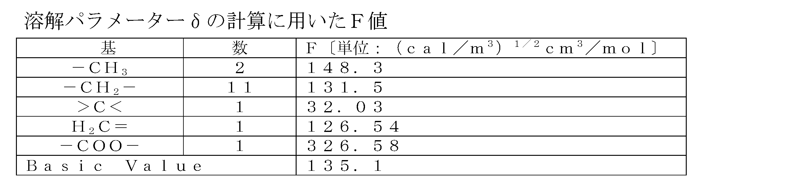
モノマー:ラウリルメタクリレート 分子量:254.4 比重:0.868)
δ=(148.3×2+131.5×11+32.03+126.54+326.58+135.1)/(254.4/0.868)=8.1(cal/m3)1/2=16.6(MPa)1/2
本明細書にいう非イオン性のモノマーとは、pHの変化によりアニオン性又はカチオン性を帯びることがないモノマーである。また、本明細書にいうアニオン性又はカチオン性モノマーとは、常にアニオン性又はカチオン性を帯びたモノマーのみならず、pHの変化によりイオン性を帯びることがあるモノマーも含む。
共重合体(A1)の重合に使用される非イオン性モノマーの溶解パラメーターは、好ましくは20.5(MPa)1/2以下、より好ましくは20.0(MPa)1/2以下、特に好ましくは18.0(MPa)1/2以下、更に好ましくは17.0(MPa)1/2以下である。
溶解パラメーターが20.5(MPa)1/2以下である非イオン性モノマーは、不飽和モノマーが好ましく、(メタ)アクリル酸の炭素数1~40、好ましくは炭素数2~24のアルキルエステル;炭素数1~40、好ましくは炭素数2~24の脂肪酸のアルケニルエステル(好ましくはビニルエステル);炭素数2~40、好ましくは3~24のアルキル変性(メタ)アクリルアミド;炭素数2~40、好ましくは3~24のアルコキシ変性(メタ)アクリルアミド;マレイン酸の炭素数1~40のモノ又はジアルキルエステル;フマル酸の炭素数1~40のモノ又はジアルキルエステル;スチレン、ビニルトルエン、α-メチルスチレン、エチレン、プロピレン、ブタジエン、イソブチレン、ジイソブチレン、ポリアルキレングリコール(メタ)アクリレート、アルコキシポリアルキレングリコール(メタ)アクリレート、ポリアルキレングリコールアルケニルエーテル、アルコキシポリアルキレングリコールアルケニルエーテル等が挙げられる。
カチオン性モノマーは不飽和モノマーが好ましく、ジメチルアミノエチル(メタ)アクリレート、ジエチルアミノエチル(メタ)アクリレート、ジメチルアミノプロピル(メタ)アクリルアミド、ジエチルアミノプロピル(メタ)アクリルアミド、アリルアミン、ジアリルアミン及びトリアリルアミンや、これらの塩類及び四級アンモニウム塩が好ましい。これらの塩類として塩酸、硫酸、酢酸、燐酸等の無機酸及び有機酸の塩類が挙げられる。これらの四級アンモニウム塩としてメチルハライド(クロライド、ブロマイド等)、エチルハライド(クロライド、ブロマイド等)、ベンジルハライド(クロライド、ブロマイド等)、ジアルキル(メチル、エチル等)硫酸、ジアルキル(メチル、エチル等)炭酸、エピクロロヒドリン等の四級化剤との反応により得られる四級アンモニウム塩が挙げられる。
なお、ジメチルアミノエチル(メタ)アクリレート、ジエチルアミノエチル(メタ)アクリレート、ジメチルアミノプロピル(メタ)アクリルアミド、ジエチルアミノプロピル(メタ)アクリルアミド、アリルアミン、ジアリルアミン、トリアリルアミンは共重合した後、塩酸、硫酸、酢酸、燐酸等の無機酸、有機酸の塩類で処理したものも用いることができる。
共重合体(A1)の重合には、上記した溶解パラメーターが20.5(MPa)1/2以下である非イオン性モノマー及びアニオン性又はカチオン性モノマーと共に、前記の各モノマーに属さないモノマーを用いることができる。これらのモノマーの割合は、全モノマーに対して0~50モル%が好ましく、0~30モル%がより好ましく、0~10モル%が特に好ましい。また、必要に応じて架橋性モノマーを用いることができる。架橋性モノマーは、前記の各モノマーに属するものであってもよく、属さない他のモノマーであってもよい。
共重合体(A1)が、溶解パラメーターが20.5(MPa)1/2以下である非イオン性モノマー単位とカチオン性モノマー単位からなる場合、各構成単位の割合(原料を基準とした割合)は、次のとおりである。
溶解パラメーターが20.5(MPa)1/2以下である非イオン性モノマー単位は、溶解パラメーターが20.5(MPa)1/2以下である非イオン性モノマーとアニオン性又はカチオン性モノマーの合計に対して、好ましくは0.5~60モル%、より好ましくは5~50モル%、より好ましくは7~40モル%、更に好ましくは10~30モル%である。この範囲は、上記非イオン性モノマー単位が炭素数12のラウリルメタクリレート、ジイソブチレン、スチレンである場合に特に好ましい。
溶解パラメーターが20.5(MPa)1/2以下である非イオン性モノマー単位は、溶解パラメーターが20.5(MPa)1/2以下である非イオン性モノマーとアニオン性又はカチオン性モノマーの合計に対して、好ましくは0.5~60モル%、より好ましくは5~50モル%、より好ましくは7~40モル%、更に好ましくは10~30モル%である。この範囲は、上記非イオン性モノマー単位が炭素数12のラウリルメタクリレート、ジイソブチレン、スチレンである場合に特に好ましい。
カチオン性またはアニオン性モノマー単位は、溶解パラメーターが20.5(MPa)1/2以下である非イオン性モノマーとアニオン性又はカチオン性モノマーの合計に対して、好ましくは50~99.5モル%、より好ましくは50~95モル%、より好ましくは60~93モル%、更に好ましくは70~90モル%である。この範囲は、上記非イオン性モノマー単位が炭素数12のラウリルメタクリレートの場合に特に好ましい。
共重合体(A1)の重量平均分子量は、1000~100万が好ましく、3000~50万がより好ましく、1万~20万が特に好ましい。
共重合体(A1)の重量平均分子量は、下記の条件でゲルパーミエーションクロマトグラフィー(GPC)にて測定したものである。換算分子量には、ポリエチレングリコール(GPC用の標準試料)を用いることができる。
<測定条件>
カラム:α-M×2(東ソー)
溶離液:50mM LiBr、1%酢酸/エタノール=70/30(体積比)
流速:1mL/min
カラム温度:40℃
検出器:RI
試料濃度:4mg/mL
注入量:100μL
共重合体(A1)の重量平均分子量は、下記の条件でゲルパーミエーションクロマトグラフィー(GPC)にて測定したものである。換算分子量には、ポリエチレングリコール(GPC用の標準試料)を用いることができる。
<測定条件>
カラム:α-M×2(東ソー)
溶離液:50mM LiBr、1%酢酸/エタノール=70/30(体積比)
流速:1mL/min
カラム温度:40℃
検出器:RI
試料濃度:4mg/mL
注入量:100μL
共重合体(A1)の重合方法は特に限定されず、溶媒、重合開始剤を用いての溶液重合や塊状重合等の公知の重合方法を適用し、回分式又は連続式で行うことができる。
共重合体(A1)の重合に用いる溶媒としては、水;メタノール、エタノール、イソプロパノール等のアルコール類;ベンゼン、トルエン、キシレン、シクロヘキサン、n-ヘプタン等の芳香族又は脂肪族炭化水素類;酢酸エチル等のエステル類;アセトン、メチルエチルケトンなどのケトン類;プロピレングリコール、エチレングリコール、ジエチレングリコール、ジエチレングリコールモノメチルエーテル、フェニルグリコール類等のグリコール系溶剤等が挙げられる。これらの中でも、各モノマー及び生成する共重合体(A1)の溶解性が良いことから、グリコール系溶剤、水及び炭素数1~4の低級アルコールから選ばれる1種又は2種以上が好ましい。
共重合体(A1)の重合に用いる重合開始剤としては、過硫酸アンモニウム、過硫酸ナトリウム、過硫酸カリウム等の過硫酸塩;過酸化水素;アゾビス-2メチルプロピオンアミジン塩酸塩、アゾイソブチロニトリル等のアゾ化合物;ベンゾイルパーオキシド、ラウロイルパーオキシド、クメンヒドロパーオキシド等のパーオキシド等が挙げられる。これらは1種又は2種以上を用いることができる。
この際、促進剤として、亜硫酸水素ナトリウム、亜硫酸ナトリウム、モール塩、ピロ重亜硫酸ナトリウム、ホルムアルデヒドナトリウムスルホキシレート、アスコルビン酸等の還元剤、エチレンジアミン、エチレンジアミン四酢酸ナトリウム、グリシン等のアミン化合物から選ばれる1種又は2種以上を併用することもできる。
この際、促進剤として、亜硫酸水素ナトリウム、亜硫酸ナトリウム、モール塩、ピロ重亜硫酸ナトリウム、ホルムアルデヒドナトリウムスルホキシレート、アスコルビン酸等の還元剤、エチレンジアミン、エチレンジアミン四酢酸ナトリウム、グリシン等のアミン化合物から選ばれる1種又は2種以上を併用することもできる。
また、重合反応時には、必要に応じて連鎖移動剤を用いることができる。連鎖移動剤としては、メルカプトエタノール、メルカプトグリセリン、メルカプトコハク酸、メルカプトプロピオン酸、メルカプトプロピオン酸2-エチルヘキシルエステル、オクタン酸2-メルカプトエチルエステル、1,8-ジメルカプト-3,6-ジオキサオクタン、デカントリチオール、ドデシルメルカプタン、ヘキサデカンチオール、デカンチオール、四塩化炭素、四臭化炭素、α-メチルスチレンダイマー、ターピノレン、α-テルピネン、γ-テルピネン、ジペンテン、2-アミノプロパン-1-オール等が挙げられる。これらは1種又は2種以上を用いることができる。
重合温度は、重合方法、溶媒、重合開始剤、連鎖移動剤の種類に応じて決められるが、通常、0~150℃の範囲内である。重合反応終了後、減圧乾燥、粉砕等の公知の精製処理をすることができる。
繊維Fの表面は、上記両親媒性重合体(A)の1種以上に加えて、両親媒性重合体(A)上に積層された、両親媒性重合体(A)以外の1種以上の重合体(B)によって、さらに改質されていてもよい。
重合体(B)は、例えば、カチオン性モノマーの一種以上に由来する構成単位を有していてもよい。当該カチオン性モノマーは、飽和モノマーが好ましく、ジメチルアミノエチル(メタ)アクリレート、ジエチルアミノエチル(メタ)アクリレート、ジメチルアミノプロピル(メタ)アクリルアミド、ジエチルアミノプロピル(メタ)アクリルアミド、アリルアミン、ジアリルアミン及びトリアリルアミンや、これらの塩類及び四級アンモニウム塩が好ましい。これらの塩類として塩酸、硫酸、酢酸、燐酸等の無機酸及び有機酸の塩類が挙げられる。これらの四級アンモニウム塩として、メチルハライド(クロライド、ブロマイド等)、エチルハライド(クロライド、ブロマイド等)、ベンジルハライド(クロライド、ブロマイド等)、ジアルキル(メチル、エチル等)硫酸、ジアルキル(メチル、エチル等)炭酸、エピクロロヒドリン等の四級化剤との反応により得られる四級アンモニウム塩が挙げられる。より具体的には塩化ジメチルジアリルアンモニウムのホモポリマーなどが好ましい。
なお、ジメチルアミノエチル(メタ)アクリレート、ジエチルアミノエチル(メタ)アクリレート、ジメチルアミノプロピル(メタ)アクリルアミド、ジエチルアミノプロピル(メタ)アクリルアミド、アリルアミン、ジアリルアミン、トリアリルアミンは、共重合した後、塩酸、硫酸、酢酸、燐酸等の無機酸、有機酸等の塩類で処理したものも用いることができる。
なお、ジメチルアミノエチル(メタ)アクリレート、ジエチルアミノエチル(メタ)アクリレート、ジメチルアミノプロピル(メタ)アクリルアミド、ジエチルアミノプロピル(メタ)アクリルアミド、アリルアミン、ジアリルアミン、トリアリルアミンは、共重合した後、塩酸、硫酸、酢酸、燐酸等の無機酸、有機酸等の塩類で処理したものも用いることができる。
重合体(B)は、例えば、アニオン性モノマーの一種以上に由来する構成単位を有していてもよい。当該アニオン性モノマーは、不飽和モノマーが好ましく、アクリル酸、メタクリル酸、マレイン酸、イタコン酸、クロトン酸、フマル酸、スルホン酸3-アリルオキシ-2-ヒドロキシプロパン、アクリルアミドメチルプロパンスルホン酸、スチレンスルホン酸およびそれらの塩からなる群より選択される少なくとも一種のモノマー10~100質量%を重合して得られる重合体(B)であることが好ましい。より具体的にはアクリル酸/マレイン酸の共重合体の軽金属塩が好ましい。
重合体(B)の重合には、上記アニオン性又はカチオン性モノマーと共に、前記の各モノマーに属さないモノマーを用いることができる。これらのモノマーの割合は、全モノマーに対して0~80モル%が好ましく、0~50モル%がより好ましく、0~20モル%が特に好ましい。また、必要に応じて架橋性モノマーを用いることができる。架橋性モノマーは、前記の各モノマーに属するものであってもよく、属さない他のモノマーであってもよい。
重合体(B)の重量平均分子量は、1000~100万が好ましく、3000~50万がより好ましく、1万~30万が特に好ましい。
重合体(B)の重量平均分子量は、共重合体(A1)と同様に、GPCにて測定することができる。換算分子量には、ポリエチレングリコール(GPC用の標準試料)を用いることができる。
重合体(B)の重量平均分子量は、共重合体(A1)と同様に、GPCにて測定することができる。換算分子量には、ポリエチレングリコール(GPC用の標準試料)を用いることができる。
本発明の改質された繊維Fの表面には、抗体3の繊維Fの表面に対する配向性を制御する観点から、Dブロック元素(C)イオンが固定されていることが好ましい。より具体的に、Dブロック元素(C)イオンは、上記両親媒性重合体(A)、又は上記両親媒性重合体(A)及び重合体(B)によって改質された繊維Fの表面に固定されていることが好ましい。
Dブロック元素(C)イオンは、Hisタグ等の特定のタグペプチドと結合されやすい。このため、抗体3の一部(例えばC末端)に上記タグペプチドを導入することにより、Dブロック元素(C)イオンが固定された繊維Fの表面に、抗体3を所望の配向で担持させやすくなる。これにより、繊維Fの表面における抗体3の配向が、標的ウイルスと結合可能な配向に制御され、抗体3の標的ウイルスに対する結合活性がより高められると考えられる。
Dブロック元素(C)イオンは、Hisタグ等の特定のタグペプチドと結合されやすい。このため、抗体3の一部(例えばC末端)に上記タグペプチドを導入することにより、Dブロック元素(C)イオンが固定された繊維Fの表面に、抗体3を所望の配向で担持させやすくなる。これにより、繊維Fの表面における抗体3の配向が、標的ウイルスと結合可能な配向に制御され、抗体3の標的ウイルスに対する結合活性がより高められると考えられる。
Dブロック元素(C)としては、以下の元素が挙げられる。
第4周期に属する元素としては、スカンジウム(Sc)、チタン(Ti)、バナジウム(V)、クロム(Cr)、マンガン(Mn)、鉄(Fe)、コバルト(Co)、ニッケル(Ni)、銅(Cu)、亜鉛(Zn)が挙げられる。
第5周期に属する元素としては、イットリウム(Y)、ジルコニウム(Zr)、ニオブ(Nb)、モリブデン(Mo)、テクネチウム(Tc)、ルテニウム(Ru)、ロジウム(Rh)、パラジウム(Pd)、銀(Ag)、カドミウム(Cd)が挙げられる。
第6周期に属する元素としては、ランタン(La)、ルテチウム(Lu)、ハフニウム(Hf)、タンタル(Ta)、タングステン(W)、レニウム(Re)、オスミウム(Os)、イリジウム(Ir)、白金(Pt)、金(Au)、水銀(Hg)が挙げられる。
第7周期に属する元素としては、アクチニウム(Ac)、ローレンシウム(Lr)、ラザホージウム(Rf)、ドブニウム(Db)、シーボーギウム(Sg)、ボーリウム(Bh)、ハッシウム(Hs)、マイトネリウム(Mt)、ダームスタチウム(Ds)、レントゲニウム(Rg)、コペルニシウム(Cn)が挙げられる。
Dブロック元素(C)としては、上記の中から選ばれる1種又は2種以上を用いることができる。
第4周期に属する元素としては、スカンジウム(Sc)、チタン(Ti)、バナジウム(V)、クロム(Cr)、マンガン(Mn)、鉄(Fe)、コバルト(Co)、ニッケル(Ni)、銅(Cu)、亜鉛(Zn)が挙げられる。
第5周期に属する元素としては、イットリウム(Y)、ジルコニウム(Zr)、ニオブ(Nb)、モリブデン(Mo)、テクネチウム(Tc)、ルテニウム(Ru)、ロジウム(Rh)、パラジウム(Pd)、銀(Ag)、カドミウム(Cd)が挙げられる。
第6周期に属する元素としては、ランタン(La)、ルテチウム(Lu)、ハフニウム(Hf)、タンタル(Ta)、タングステン(W)、レニウム(Re)、オスミウム(Os)、イリジウム(Ir)、白金(Pt)、金(Au)、水銀(Hg)が挙げられる。
第7周期に属する元素としては、アクチニウム(Ac)、ローレンシウム(Lr)、ラザホージウム(Rf)、ドブニウム(Db)、シーボーギウム(Sg)、ボーリウム(Bh)、ハッシウム(Hs)、マイトネリウム(Mt)、ダームスタチウム(Ds)、レントゲニウム(Rg)、コペルニシウム(Cn)が挙げられる。
Dブロック元素(C)としては、上記の中から選ばれる1種又は2種以上を用いることができる。
このうち、Dブロック元素(C)としては、抗体3の配向性をより確実に制御する観点から、第4周期に属する元素が好ましく、鉄(Fe)、コバルト(Co)、ニッケル(Ni)、銅(Cu)、亜鉛(Zn)の中から選ばれる1種以上を使用することが好ましく、ニッケル(Ni)を使用することがさらに好ましい。
改質された繊維Fの表面にDブロック元素(C)のイオンを処理する際の溶媒は、水が好ましく、水溶性の塩化物、硫酸化物、硝酸化物などのDブロック元素(C)の塩で供給することが好ましい。Dブロック元素(C)の塩の処理溶液濃度は、0.01%~30質量%が好ましく、0.1~5質量%の範囲がより好ましい。
(繊維集合体の具体的な構成例)
本発明の繊維Fは、繊維集合体2において、互いに融着し、及び/又は絡み合っていることが好ましい。
「融着」とは、繊維F同士が溶融して接着した状態を意味する。
「絡み合い」とは、繊維F同士が互いに絡んだ状態を意味する。
さらに、繊維集合体2が、繊維Fの表面又は繊維F間に接着剤を含んでおらず、融着及び又は絡み合いによって形状を保持していることが好ましい。本発明の繊維Fは、非常に細い径を有するため、特に融着や絡み合いが起きやすい。したがって、繊維集合体2は、接着剤を含まずとも良好に形状を保持することが可能となる。
これにより、繊維Fの表面に接着剤が存在しない状態となり、抗体3のウイルス結合活性が維持される。したがって、繊維集合体2による高いウイルス吸着量が維持され、ウイルスの濃縮率がより確実に向上する。また、接着剤を用いないことでウイルス検査をより精度よく実施することができ、ウイルス濃縮用材料1が医療用の材料としてより適したものとなる。
本発明の繊維Fは、繊維集合体2において、互いに融着し、及び/又は絡み合っていることが好ましい。
「融着」とは、繊維F同士が溶融して接着した状態を意味する。
「絡み合い」とは、繊維F同士が互いに絡んだ状態を意味する。
さらに、繊維集合体2が、繊維Fの表面又は繊維F間に接着剤を含んでおらず、融着及び又は絡み合いによって形状を保持していることが好ましい。本発明の繊維Fは、非常に細い径を有するため、特に融着や絡み合いが起きやすい。したがって、繊維集合体2は、接着剤を含まずとも良好に形状を保持することが可能となる。
これにより、繊維Fの表面に接着剤が存在しない状態となり、抗体3のウイルス結合活性が維持される。したがって、繊維集合体2による高いウイルス吸着量が維持され、ウイルスの濃縮率がより確実に向上する。また、接着剤を用いないことでウイルス検査をより精度よく実施することができ、ウイルス濃縮用材料1が医療用の材料としてより適したものとなる。
(ウイルス濃縮用材料の具体的な構成例)
本発明のウイルス濃縮用材料1は、繊維集合体2を検査対象液に接触可能とする観点から、種々の構成を採り得る。
ウイルス濃縮用材料1は、繊維集合体2と、抗体3と、に加えて、繊維集合体2を保持する一端部4aと、一端部4aから延びる延在部4bと、を含む保持部材4をさらに備えていてもよい。その例は図1~図4に示されている。
延在部4bは、一端部4aから1又は複数の方向に延びる長い形状を有し、好ましくは一端部4aから一方向に延びる形状を有する。延在部4bは、全体として長く延びていればよく、一部が湾曲若しくは屈曲している形状、一部が太くなっている形状、一部にスリットや突起等の構造を有する形状、及び分岐している形状等を有していてもよい。
延在部4bは、ヒトが指でつまめる大きさであることが好ましい。
保持部材4は、具体的には、剛体又は弾性部材等で構成された棒、不織布等のシート材等で構成されることが好ましい。
「一端部4aが繊維集合体2を保持する」とは、一端部4aが、少なくとも濃縮処理の間、繊維集合体2と接続された状態を維持できることを意味する。
保持部材4は、ウイルス濃縮用材料1の使用時において、例えば一端部4a側で繊維集合体2を保持しつつ、延在部4bをユーザに把持される。これにより、保持部材4を把持した当該ユーザが、検査対象液に、繊維集合体2を衛生的に接触させることができる。
本発明のウイルス濃縮用材料1は、繊維集合体2を検査対象液に接触可能とする観点から、種々の構成を採り得る。
ウイルス濃縮用材料1は、繊維集合体2と、抗体3と、に加えて、繊維集合体2を保持する一端部4aと、一端部4aから延びる延在部4bと、を含む保持部材4をさらに備えていてもよい。その例は図1~図4に示されている。
延在部4bは、一端部4aから1又は複数の方向に延びる長い形状を有し、好ましくは一端部4aから一方向に延びる形状を有する。延在部4bは、全体として長く延びていればよく、一部が湾曲若しくは屈曲している形状、一部が太くなっている形状、一部にスリットや突起等の構造を有する形状、及び分岐している形状等を有していてもよい。
延在部4bは、ヒトが指でつまめる大きさであることが好ましい。
保持部材4は、具体的には、剛体又は弾性部材等で構成された棒、不織布等のシート材等で構成されることが好ましい。
「一端部4aが繊維集合体2を保持する」とは、一端部4aが、少なくとも濃縮処理の間、繊維集合体2と接続された状態を維持できることを意味する。
保持部材4は、ウイルス濃縮用材料1の使用時において、例えば一端部4a側で繊維集合体2を保持しつつ、延在部4bをユーザに把持される。これにより、保持部材4を把持した当該ユーザが、検査対象液に、繊維集合体2を衛生的に接触させることができる。
保持部材4を備えたウイルス濃縮用材料1は、繊維集合体2と保持部材4とが一体に接続されていてもよい。
本明細書において、「保持部材4が繊維集合体2に接続される」とは、保持部材4と繊維集合体2が分離不可能に一体化することを意味する。
一実施形態において、ウイルス濃縮用材料1が綿棒状に構成される。この例において、繊維集合体2は綿状であり、保持部材4は紙、木材又はプラスチック等で形成された棒であり得る。一端部4aは、繊維集合体2に覆われた状態となる。その例は図1に示されている。
「棒」とは、全体として細長い構造物を意味する。棒状の延在部4bは、長手方向に直交する断面が一様な棒に限定されず、一部が太くなっている形態、一部にスリットや突起等の構造を有する形態、一部が湾曲若しくは屈曲している形態、及び分岐している形態等を含む。
繊維集合体2と保持部材4との接続方法は限定されないが、保持部材4は、接着剤を介さずに繊維集合体2を保持することが好ましく、保持部材4表面に繊維集合体2が直接接して保持されていることが好ましい。この場合、繊維集合体2は、一端部4aに繊維Fが絡み付くことによって保持部材4に接続される。繊維集合体2では、繊維Fの繊維径が細いため、繊維Fが保持部材4の周りに絡み付きやすく、接着剤を含まずとも保持部材4との接続状態を維持することが可能となる。これにより、接着剤による繊維集合体2のウイルス吸着量の低下が抑制されるとともに、ウイルス濃縮用材料1が医療用の材料としてより適したものとなる。
本明細書において、「保持部材4が繊維集合体2に接続される」とは、保持部材4と繊維集合体2が分離不可能に一体化することを意味する。
一実施形態において、ウイルス濃縮用材料1が綿棒状に構成される。この例において、繊維集合体2は綿状であり、保持部材4は紙、木材又はプラスチック等で形成された棒であり得る。一端部4aは、繊維集合体2に覆われた状態となる。その例は図1に示されている。
「棒」とは、全体として細長い構造物を意味する。棒状の延在部4bは、長手方向に直交する断面が一様な棒に限定されず、一部が太くなっている形態、一部にスリットや突起等の構造を有する形態、一部が湾曲若しくは屈曲している形態、及び分岐している形態等を含む。
繊維集合体2と保持部材4との接続方法は限定されないが、保持部材4は、接着剤を介さずに繊維集合体2を保持することが好ましく、保持部材4表面に繊維集合体2が直接接して保持されていることが好ましい。この場合、繊維集合体2は、一端部4aに繊維Fが絡み付くことによって保持部材4に接続される。繊維集合体2では、繊維Fの繊維径が細いため、繊維Fが保持部材4の周りに絡み付きやすく、接着剤を含まずとも保持部材4との接続状態を維持することが可能となる。これにより、接着剤による繊維集合体2のウイルス吸着量の低下が抑制されるとともに、ウイルス濃縮用材料1が医療用の材料としてより適したものとなる。
繊維集合体2と保持部材4とが一体に接続されたウイルス濃縮用材料1は、他の実施形態として、積層構造を有するシート状の繊維集合体2を備えていてもよい。繊維集合体2は、好ましくは、保持部材4の一端部4aの表裏を覆うように積層されている。繊維集合体2は、積層構造を維持するとともに、後述する貫通孔4dを介して保持部材4に接続される観点から、貫通孔4dを挟んで対向する繊維集合体2同士が貫通孔4dを介して接合された接合部4eを含むことが好ましい。この例は、図2(E)に示されている。
図2(E)に示す構成を実現するため、ウイルス濃縮用材料1は、図2(A)に示すように、一端部4aに貫通孔4dを含む棒状の保持部材4を備えることが好ましい。貫通孔4dの平面形状は特に限定されず、図2(A)に示すような矩形状の他、円形状、楕円形状等の任意の形状を採り得る。
図2(E)に示すウイルス濃縮用材料1の作製方法の一例について説明する。
まず、図2(A)に示すような棒状の保持部材4を準備する。この保持部材4は、プラスチック、紙、又は木材等で構成され得るが、成形性の観点から、プラスチックで構成されることが好ましい。
そして、図2(B)及び(C)に示すように、この保持部材4の貫通孔4dを覆うように、シート状の繊維集合体2が折り畳まれて配置される。
そして、図2(D)に示すように、貫通孔4dを挟んで対向する繊維集合体2同士が、貫通孔4dを介して接合され、接合部4eが形成される。接合部4eは、熱シール又は超音波シール等による融着によって形成されることが好ましい。これにより、保持部材4と繊維集合体2とが接続される。
そして、図2(D)の繊維集合体2の周縁部を切除することにより、図2(E)の構成のウイルス濃縮用材料1が作製される。
図2(E)に示す構成を実現するため、ウイルス濃縮用材料1は、図2(A)に示すように、一端部4aに貫通孔4dを含む棒状の保持部材4を備えることが好ましい。貫通孔4dの平面形状は特に限定されず、図2(A)に示すような矩形状の他、円形状、楕円形状等の任意の形状を採り得る。
図2(E)に示すウイルス濃縮用材料1の作製方法の一例について説明する。
まず、図2(A)に示すような棒状の保持部材4を準備する。この保持部材4は、プラスチック、紙、又は木材等で構成され得るが、成形性の観点から、プラスチックで構成されることが好ましい。
そして、図2(B)及び(C)に示すように、この保持部材4の貫通孔4dを覆うように、シート状の繊維集合体2が折り畳まれて配置される。
そして、図2(D)に示すように、貫通孔4dを挟んで対向する繊維集合体2同士が、貫通孔4dを介して接合され、接合部4eが形成される。接合部4eは、熱シール又は超音波シール等による融着によって形成されることが好ましい。これにより、保持部材4と繊維集合体2とが接続される。
そして、図2(D)の繊維集合体2の周縁部を切除することにより、図2(E)の構成のウイルス濃縮用材料1が作製される。
さらに他の実施形態として、ウイルス濃縮用材料1は、シート材を有する延在部4bを含む保持部材4を備えていてもよい。延在部4bは、典型的には細長い形状の1又は2以上のシート材を含み、好ましくはシート材の積層構造を有する。当該シート材は、不織布、織布、又は紙等で構成され得るが、後述する接合部4jを容易に形成する観点から、不織布で構成されることが好ましい。なお、延在部4bに用いられる「不織布」は、本発明の繊維集合体2とは異なる構成を有する不織布である。
この実施形態において、繊維集合体2は、典型的にはシート状であって、好ましくは積層構造を有する。この例は、図3(C)に示されている。
図3(C)に示すウイルス濃縮用材料1の作製方法の一例について説明する。
図3(A)に示すように、延在部4bに用いられるシート材4fと、シート状の繊維集合体2とが積層され、積層体4gが形成される。シート状の繊維集合体2の一部は、シート材4fの一端部4hと重なるように配置される。
続いて、図3(B)に示すように、シート材4fと繊維集合体2とを接合する接合部4jが形成される。接合部4jは、熱シール又は超音波シール等による融着によって形成されることが好ましい。接合部4jは、上記一方向に沿って、シート材4fから繊維集合体2まで延びることが好ましい。
接合部4jに沿って、積層体4gの上記一方向の全長にわたって切断することで、図3(C)に示すウイルス濃縮用材料1が作製される。
上記製造方法により、図3(C)に示すウイルス濃縮用材料1は、延在部4bから繊維集合体2まで延びる接合部4jを含む。この接合部4jは、好ましくはウイルス濃縮用材料1の側縁部に沿って配置される。この例では、接合部4jにより、保持部材4と繊維集合体2とが接続される。
この実施形態において、繊維集合体2は、典型的にはシート状であって、好ましくは積層構造を有する。この例は、図3(C)に示されている。
図3(C)に示すウイルス濃縮用材料1の作製方法の一例について説明する。
図3(A)に示すように、延在部4bに用いられるシート材4fと、シート状の繊維集合体2とが積層され、積層体4gが形成される。シート状の繊維集合体2の一部は、シート材4fの一端部4hと重なるように配置される。
続いて、図3(B)に示すように、シート材4fと繊維集合体2とを接合する接合部4jが形成される。接合部4jは、熱シール又は超音波シール等による融着によって形成されることが好ましい。接合部4jは、上記一方向に沿って、シート材4fから繊維集合体2まで延びることが好ましい。
接合部4jに沿って、積層体4gの上記一方向の全長にわたって切断することで、図3(C)に示すウイルス濃縮用材料1が作製される。
上記製造方法により、図3(C)に示すウイルス濃縮用材料1は、延在部4bから繊維集合体2まで延びる接合部4jを含む。この接合部4jは、好ましくはウイルス濃縮用材料1の側縁部に沿って配置される。この例では、接合部4jにより、保持部材4と繊維集合体2とが接続される。
さらに他の実施形態として、保持部材4は、一端部4aに形成された、繊維集合体2の取り付けが可能な取付部4cを含んでいてもよい。
本明細書において、「保持部材4が繊維集合体2に取り付けられる」とは、保持部材4が、分離可能な状態で繊維集合体2に取り付けられることを意味する。
一実施形態において、取付部4cは、繊維集合体2を挟むことが可能なスリットで構成される。繊維集合体2は、例えば、取付部4cのスリットに挟まれることが可能なシート状に構成される。その例は図4に示されている。
取付部4cは、スリットに限定されず、繊維集合体2を取り付けることが可能な種々の形態を採り得る。例えば取付部4cは、繊維集合体2の一部に挿入可能な突起を含んでいてもよい。あるいは、取付部4cは、繊維集合体2を挟むことが可能なクリップ状構造を含んでいてもよい。取付部4cは、繊維を挟むことが可能なクリップ状構造を含んでいてもよい。
保持部材4は、取付部4cを容易に成形する観点から、プラスチックで形成されることが好ましい。
この例において、ウイルス濃縮用材料1は、繊維集合体2と保持部材4とが分離された状態で製造、流通及び保存され、使用時に、ユーザによって保持部材4が繊維集合体2に取り付けられる。これによっても、繊維集合体2が接着剤を介さずに保持部材4に取り付けられるため、接着剤による繊維集合体2のウイルス吸着量の低下が抑制されるとともに、ウイルス濃縮用材料1が医療用の材料としてより適したものとなる。さらに、ウイルス濃縮用材料1の製造過程において保持部材4と繊維集合体2とを接続する工程が不要となり、製造効率が高められる。
本明細書において、「保持部材4が繊維集合体2に取り付けられる」とは、保持部材4が、分離可能な状態で繊維集合体2に取り付けられることを意味する。
一実施形態において、取付部4cは、繊維集合体2を挟むことが可能なスリットで構成される。繊維集合体2は、例えば、取付部4cのスリットに挟まれることが可能なシート状に構成される。その例は図4に示されている。
取付部4cは、スリットに限定されず、繊維集合体2を取り付けることが可能な種々の形態を採り得る。例えば取付部4cは、繊維集合体2の一部に挿入可能な突起を含んでいてもよい。あるいは、取付部4cは、繊維集合体2を挟むことが可能なクリップ状構造を含んでいてもよい。取付部4cは、繊維を挟むことが可能なクリップ状構造を含んでいてもよい。
保持部材4は、取付部4cを容易に成形する観点から、プラスチックで形成されることが好ましい。
この例において、ウイルス濃縮用材料1は、繊維集合体2と保持部材4とが分離された状態で製造、流通及び保存され、使用時に、ユーザによって保持部材4が繊維集合体2に取り付けられる。これによっても、繊維集合体2が接着剤を介さずに保持部材4に取り付けられるため、接着剤による繊維集合体2のウイルス吸着量の低下が抑制されるとともに、ウイルス濃縮用材料1が医療用の材料としてより適したものとなる。さらに、ウイルス濃縮用材料1の製造過程において保持部材4と繊維集合体2とを接続する工程が不要となり、製造効率が高められる。
さらに他の実施形態として、ウイルス濃縮用材料1は、保持部材4を備えず、繊維集合体2と、抗体3と、で構成されてもよい。図5に示す例では、繊維集合体2がシート状に構成され、図6に示す例では、繊維集合体2が綿状に構成される。これらの構成のウイルス濃縮用材料1でも、繊維集合体2をピンセット等の器具で摘まんで、検査対象液と接触させることができる。このような構成のウイルス濃縮用材料1により、製造コストを低減できるとともに、製造効率がより高められる。
(抗体)
本発明の抗体3は、繊維Fの表面に担持される。抗体3により、検査対象液中のウイルスが繊維集合体2に吸着し、繊維集合体2がウイルスに対する吸着能を発揮できる。この繊維集合体2のウイルス吸着能によって、検査対象液中のウイルスが繊維集合体2上に吸着し、ウイルスが濃縮される。以下、抗体3の構成について説明する。
本発明の抗体3は、繊維Fの表面に担持される。抗体3により、検査対象液中のウイルスが繊維集合体2に吸着し、繊維集合体2がウイルスに対する吸着能を発揮できる。この繊維集合体2のウイルス吸着能によって、検査対象液中のウイルスが繊維集合体2上に吸着し、ウイルスが濃縮される。以下、抗体3の構成について説明する。
本発明の抗体3は、典型的には、標的ウイルスのタンパク質の一部と特異的に結合することが可能なCDRを含む構造ドメインを有する。CDR(Complementarity Determining Region;相補性決定領域)とは、配列可変な抗原認識部位又はランダム配列領域を含み、超可変領域とも言われる。CDRのアミノ酸配列等により、標的ウイルスへの結合性が制御される。
抗体3が認識可能なタンパク質としては、例えば、標的ウイルスのスパイクタンパク質(Sタンパク質)、ヌクレオチドタンパク質(Nタンパク質)、エンベロープタンパク質(Eタンパク質)、マトリックスタンパク質等が挙げられる。ウイルスそのものを吸着させるためには、抗体3は、ウイルスの表面に存在しているスパイクタンパク質に結合することが好ましく、スパイクタンパク質のS1タンパク質に結合することがより好ましい。
抗体3が認識可能なタンパク質としては、例えば、標的ウイルスのスパイクタンパク質(Sタンパク質)、ヌクレオチドタンパク質(Nタンパク質)、エンベロープタンパク質(Eタンパク質)、マトリックスタンパク質等が挙げられる。ウイルスそのものを吸着させるためには、抗体3は、ウイルスの表面に存在しているスパイクタンパク質に結合することが好ましく、スパイクタンパク質のS1タンパク質に結合することがより好ましい。
「抗体3が繊維Fの表面に担持される」とは、ウイルス濃縮用材料1の保存及び流通時、及び検査対象液への繊維集合体2の接触時に、多くの抗体3が繊維Fから脱離しないで繊維Fの表面に固定されている状態を意味する。ウイルス結合活性を有する多くの抗体3を繊維Fの表面に担持する観点から、抗体3は、抗体3の分子と繊維Fに含まれる分子との親和性を利用して繊維Fに担持されることが好ましい。当該親和性を利用した抗体3と繊維Fとの担持方法としては、例えば、共有結合、疎水結合、水素結合、静電結合、その他の分子間力(ファン・デル・ワールス力)による結合が挙げられる。
抗体3は、ウイルスの繊維Fへの吸着率を向上させる観点から、標的ウイルスへの結合活性が高い状態で繊維Fの表面に担持されることが好ましい。このような観点から、抗体3は、CDRがウイルスと結合可能な配向で繊維Fの表面に担持されることが好ましい。このため、抗体3は、CDRから立体構造上離れているC末端側で繊維Fに担持されることがより好ましい。
抗体3の繊維Fの表面に対する配向性を制御する観点から、抗体3は、タグペプチドを介して繊維Fの表面に配置されていることが好ましい。当該タグペプチドは、抗体3のアフィニティタグとして機能し、繊維Fと親和性の高いアミノ酸配列を有する。当該タグペプチドは、抗体3をより好ましい配向に制御する観点から、抗体3のC末端に結合していることがより好ましい。これにより、抗体3のC末端側がタグペプチドを介して繊維Fの表面に担持され、CDRが外側を向き、抗体3が標的ウイルスと結合しやすい配向となる。
より具体的に、当該タグペプチドは、配列番号1~16で示されるアミノ酸配列から選ばれる1種又は2種以上のアミノ酸配列を含んでいることが好ましい。配列番号1~15で示されるアミノ酸配列を有するタグペプチドは、特にポリプロピレンとの親和性が高いため、繊維Fがポリプロピレンを有する場合に、抗体3の配向性がより確実に制御される。配列番号16で示されるアミノ酸配列を有するタグペプチドは、特にニッケルやコバルト、銅などの金属イオンとの親和性が高いため、繊維Fがニッケルやコバルト、銅などの金属イオンを有する場合に、抗体3の配向性がより確実に制御される。
ここで、配列番号1で示されるアミノ酸配列はTSDIKSRSPHHRである。配列番号2で示されるアミノ酸配列はMPAVMSSAQVPRである。配列番号3で示されるアミノ酸配列はSMKYSHSTAPALである。配列番号4で示されるアミノ酸配列はLYARDVSRYWHVである。配列番号5で示されるアミノ酸配列はHTQNMRMYEPWFである。配列番号6で示されるアミノ酸配列はLPPGSLAである。配列番号7で示されるアミノ酸配列はNQSFLPLDFPFRである。配列番号8で示されるアミノ酸配列はSILSTMSPHGATである。配列番号9で示されるアミノ酸配列はSCTLERCMYRNGである。配列番号10で示されるアミノ酸配列はNFLGAVAKGAIHである。配列番号11で示されるアミノ酸配列はHVSTTDLLGPRRである。配列番号12で示されるアミノ酸配列はDYHDPSLPTLRKである。配列番号13で示されるアミノ酸配列はGNNPLHVHHDKRである。配列番号14で示されるアミノ酸配列はVCSPCGPVPPAKである。配列番号15で示されるアミノ酸配列はRFFDSEFDVAFHである。配列番号16で示されるアミノ酸配列はHHHHHHである。
抗体3をより好ましい配向に制御する観点から、タグペプチドはヒンジペプチドを介して抗体3のC末端に結合していることが好ましい。より具体的に、当該ヒンジペプチドは、配列番号17~19で示されるアミノ酸配列から選ばれる1種又は2種以上のアミノ酸配列を含んでいることが好ましい。ここで、配列番号17で示されるアミノ酸配列はEPKTPKPQSである。配列番号18で示されるアミノ酸配列はGGGである。配列番号19で示されるアミノ酸配列はGGGSである。
抗体3の繊維Fの表面に対する配向性を制御する観点から、抗体3は、タグペプチドを介して繊維Fの表面に配置されていることが好ましい。当該タグペプチドは、抗体3のアフィニティタグとして機能し、繊維Fと親和性の高いアミノ酸配列を有する。当該タグペプチドは、抗体3をより好ましい配向に制御する観点から、抗体3のC末端に結合していることがより好ましい。これにより、抗体3のC末端側がタグペプチドを介して繊維Fの表面に担持され、CDRが外側を向き、抗体3が標的ウイルスと結合しやすい配向となる。
より具体的に、当該タグペプチドは、配列番号1~16で示されるアミノ酸配列から選ばれる1種又は2種以上のアミノ酸配列を含んでいることが好ましい。配列番号1~15で示されるアミノ酸配列を有するタグペプチドは、特にポリプロピレンとの親和性が高いため、繊維Fがポリプロピレンを有する場合に、抗体3の配向性がより確実に制御される。配列番号16で示されるアミノ酸配列を有するタグペプチドは、特にニッケルやコバルト、銅などの金属イオンとの親和性が高いため、繊維Fがニッケルやコバルト、銅などの金属イオンを有する場合に、抗体3の配向性がより確実に制御される。
ここで、配列番号1で示されるアミノ酸配列はTSDIKSRSPHHRである。配列番号2で示されるアミノ酸配列はMPAVMSSAQVPRである。配列番号3で示されるアミノ酸配列はSMKYSHSTAPALである。配列番号4で示されるアミノ酸配列はLYARDVSRYWHVである。配列番号5で示されるアミノ酸配列はHTQNMRMYEPWFである。配列番号6で示されるアミノ酸配列はLPPGSLAである。配列番号7で示されるアミノ酸配列はNQSFLPLDFPFRである。配列番号8で示されるアミノ酸配列はSILSTMSPHGATである。配列番号9で示されるアミノ酸配列はSCTLERCMYRNGである。配列番号10で示されるアミノ酸配列はNFLGAVAKGAIHである。配列番号11で示されるアミノ酸配列はHVSTTDLLGPRRである。配列番号12で示されるアミノ酸配列はDYHDPSLPTLRKである。配列番号13で示されるアミノ酸配列はGNNPLHVHHDKRである。配列番号14で示されるアミノ酸配列はVCSPCGPVPPAKである。配列番号15で示されるアミノ酸配列はRFFDSEFDVAFHである。配列番号16で示されるアミノ酸配列はHHHHHHである。
抗体3をより好ましい配向に制御する観点から、タグペプチドはヒンジペプチドを介して抗体3のC末端に結合していることが好ましい。より具体的に、当該ヒンジペプチドは、配列番号17~19で示されるアミノ酸配列から選ばれる1種又は2種以上のアミノ酸配列を含んでいることが好ましい。ここで、配列番号17で示されるアミノ酸配列はEPKTPKPQSである。配列番号18で示されるアミノ酸配列はGGGである。配列番号19で示されるアミノ酸配列はGGGSである。
ウイルス濃縮用材料1によってウイルスの濃縮率を向上させる観点からは、多くの抗体3が繊維集合体2に担持されていることが好ましい。このような観点から、抗体3が担持された繊維集合体2の1g当たりにおける抗体3の含有量は、好ましくは1mg/g以上、より好ましくは1.5mg/g以上、さらに好ましくは3mg/g以上である。また、繊維Fの表面における抗体3の密度を適切に制御し、抗体3のウイルスとの結合活性を確保する観点や製造コストの観点から、抗体3が担持された繊維集合体2の1g当たりにおける抗体3の含有量は、好ましくは60mg/g以下、より好ましくは30mg/g以下、さらに好ましくは15mg/g以下である。
なお、「抗体3が担持された繊維集合体2の1g当たりにおける抗体3の含有量」とは、抗体3及びそれが担持された繊維集合体2全体の1g当たりにおける抗体3の含有量を意味するものとする。
抗体3の含有量は、以下のように測定することができる。繊維集合体2から抗体3を界面活性剤溶液等の公知のタンパク質溶出液で溶出し、溶出された抗体溶液中の抗体濃度を測定することで求めることができる。抗体濃度は、公知のタンパク質濃度測定法で求めることができるが、抗体特異的な測定法である、抗体測定用ELISAキットや電気泳動後にタンパク質染色液で染色後、抗体3のバンドの量を定量することで求めることが好ましい。
なお、「抗体3が担持された繊維集合体2の1g当たりにおける抗体3の含有量」とは、抗体3及びそれが担持された繊維集合体2全体の1g当たりにおける抗体3の含有量を意味するものとする。
抗体3の含有量は、以下のように測定することができる。繊維集合体2から抗体3を界面活性剤溶液等の公知のタンパク質溶出液で溶出し、溶出された抗体溶液中の抗体濃度を測定することで求めることができる。抗体濃度は、公知のタンパク質濃度測定法で求めることができるが、抗体特異的な測定法である、抗体測定用ELISAキットや電気泳動後にタンパク質染色液で染色後、抗体3のバンドの量を定量することで求めることが好ましい。
抗体3は、具体的には、IgG抗体、重鎖抗体、及びフラグメント抗体から選ばれる1種又は2種以上であることが好ましい。
IgG抗体は、重鎖(VH)及び軽鎖(LH)からなり、重鎖及び軽鎖がそれぞれCDR1,CDR2,CDR3の3つのCDRを有する。
重鎖抗体は、重鎖のみからなり、CDR1,CDR2,CDR3の3つのCDRを有する。
フラグメント抗体は、酵素や遺伝子工学的な手法を用いて断片化された抗体であり、Fab、F(ab')2、Fv、VHH抗体等を含む。
特に、抗体3としてフラグメント抗体を用いることで、IgG抗体よりも抗体3の分子量を小さくことができ、より多くの抗体3を繊維Fの表面に担持することができる。したがって、繊維集合体2のウイルス吸着量が向上し、ウイルスの濃縮率がより確実に向上する。
IgG抗体は、重鎖(VH)及び軽鎖(LH)からなり、重鎖及び軽鎖がそれぞれCDR1,CDR2,CDR3の3つのCDRを有する。
重鎖抗体は、重鎖のみからなり、CDR1,CDR2,CDR3の3つのCDRを有する。
フラグメント抗体は、酵素や遺伝子工学的な手法を用いて断片化された抗体であり、Fab、F(ab')2、Fv、VHH抗体等を含む。
特に、抗体3としてフラグメント抗体を用いることで、IgG抗体よりも抗体3の分子量を小さくことができ、より多くの抗体3を繊維Fの表面に担持することができる。したがって、繊維集合体2のウイルス吸着量が向上し、ウイルスの濃縮率がより確実に向上する。
さらに、抗体3は、フラグメント抗体の中でもVHH抗体であることがより好ましい。VHH抗体は、重鎖抗体のフラグメント抗体であって、ラクダ科動物の血清中から見出されたシングルドメイン抗体である。VHH抗体は、CDR1,CDR2,CDR3の3つのCDRを含む構造ドメインを有する。当該構造ドメインにおいて、3つのCDRは、例えば、N末端側からCDR1、CDR2、CDR3の順で存在する。
また、IgG抗体は動物培養細胞を用いて生産する必要があるが、VHH抗体は大腸菌や酵母で生産できる。また、VHH抗体は、遺伝子工学的に改変が容易であり、上述のタグ(ペプチド)の導入等が容易である。さらに、VHH抗体は、熱などに対しても耐性が高く、安定した結合活性を維持できる。これらの特徴から、抗体3としてVHH抗体を用いることで、安定した濃縮能を有するウイルス濃縮用材料1を高い生産性で得ることができる。
また、IgG抗体は動物培養細胞を用いて生産する必要があるが、VHH抗体は大腸菌や酵母で生産できる。また、VHH抗体は、遺伝子工学的に改変が容易であり、上述のタグ(ペプチド)の導入等が容易である。さらに、VHH抗体は、熱などに対しても耐性が高く、安定した結合活性を維持できる。これらの特徴から、抗体3としてVHH抗体を用いることで、安定した濃縮能を有するウイルス濃縮用材料1を高い生産性で得ることができる。
抗体3の標的ウイルスは、ヒト及び家畜への感染が報告されている病原性のウイルスであり、ウイルス検査の必要性が高い、コロナウイルス、インフルエンザウイルス、ノロウイルス、ロタウイルス、アデノウイルス、及びサポウイルスから選ばれる1種又は2種以上であることが好ましい。
特に、抗体3の標的ウイルスは、コロナウイルスに属するSARS-CoV-2であることがより好ましい。SARS-CoV-2は、急性呼吸器疾患(COVID-19)の原因となるウイルスである。本発明によって検査対象液中のSARS-CoV-2を簡便かつ高い濃縮率で濃縮することで、ウイルス検査におけるSARS-CoV-2の検出感度が向上する。これにより、感染初期の患者や無症状の患者に対してもCOVID-19が診断される可能性が高まる。さらに、後述するように、本発明では非常に迅速かつ簡便に標的ウイルスの濃縮が可能となり、検査効率が高められる。したがって、本発明により、SARS-CoV-2の感染防止策が適切に講じられ、COVID-19の拡大防止に貢献できる。
特に、抗体3の標的ウイルスは、コロナウイルスに属するSARS-CoV-2であることがより好ましい。SARS-CoV-2は、急性呼吸器疾患(COVID-19)の原因となるウイルスである。本発明によって検査対象液中のSARS-CoV-2を簡便かつ高い濃縮率で濃縮することで、ウイルス検査におけるSARS-CoV-2の検出感度が向上する。これにより、感染初期の患者や無症状の患者に対してもCOVID-19が診断される可能性が高まる。さらに、後述するように、本発明では非常に迅速かつ簡便に標的ウイルスの濃縮が可能となり、検査効率が高められる。したがって、本発明により、SARS-CoV-2の感染防止策が適切に講じられ、COVID-19の拡大防止に貢献できる。
抗体3の標的ウイルスがSARS-CoV-2である場合、抗体3は、CDR1,CDR2及びCDR3を含む下記1)、2)又は3)の構造ドメインを1つ以上有することが好ましい。
1)の構造ドメインは、配列番号20で示されるアミノ酸配列又は当該アミノ酸配列において1個のアミノ酸が他のアミノ酸に置換されたアミノ酸配列からなるCDR1と、
配列番号21で示されるアミノ酸配列又は当該アミノ酸配列において1個のアミノ酸が他のアミノ酸に置換されたアミノ酸配列からなるCDR2と、
配列番号22で示されるアミノ酸配列又は当該アミノ酸配列において1個のアミノ酸が他のアミノ酸に置換されたアミノ酸配列からなるCDR3と、を含む。
ここで、配列番号20で示されるアミノ酸配列はGSTFSDYVMAであり、配列番号21で示されるアミノ酸配列はTISRNGGTTTであり、配列番号22で示されるアミノ酸配列はVGGDGDSである。これらのCDR配列を有する抗体としてはCoVHH1(配列番号23)がある。
2)の構造ドメインは、配列番号24で示されるアミノ酸配列又は当該アミノ酸配列において1個のアミノ酸が他のアミノ酸に置換されたアミノ酸配列からなるCDR1と、
配列番号25で示されるアミノ酸配列又は当該アミノ酸配列において1個のアミノ酸が他のアミノ酸に置換されたアミノ酸配列からなるCDR2と、
配列番号26で示されるアミノ酸配列又は当該アミノ酸配列において1個のアミノ酸が他のアミノ酸に置換されたアミノ酸配列からなるCDR3と、を含む。
ここで、配列番号24で示されるアミノ酸配列はDQIFDNYNMAであり、配列番号25で示されるアミノ酸配列はALSWGDSNTGであり、配列番号26で示されるアミノ酸配列はVTWLRGDYである。これらCDRを有する抗体としてはCoVHH-E5(配列番号27)がある。
3)の構造ドメインは、配列番号28で示されるアミノ酸配列又は当該アミノ酸配列において1個のアミノ酸が他のアミノ酸に置換されたアミノ酸配列からなるCDR1と、
配列番号29で示されるアミノ酸配列又は当該アミノ酸配列において1個のアミノ酸が他のアミノ酸に置換されたアミノ酸配列からなるCDR2と、
配列番号30で示されるアミノ酸配列又は当該アミノ酸配列において1個のアミノ酸が他のアミノ酸に置換されたアミノ酸配列からなるCDR3と、を含む。
ここで、配列番号28で示されるアミノ酸配列はGTIFSTNAMSであり、配列番号29で示されるアミノ酸配列はAITSGGNTNであり、配列番号30に示されるアミノ酸配列はPGVVTGSYDVRNYである。これらCDRを有する抗体としてはCoVHH-E9(配列番号31)がある。
1)の構造ドメインは、配列番号20で示されるアミノ酸配列又は当該アミノ酸配列において1個のアミノ酸が他のアミノ酸に置換されたアミノ酸配列からなるCDR1と、
配列番号21で示されるアミノ酸配列又は当該アミノ酸配列において1個のアミノ酸が他のアミノ酸に置換されたアミノ酸配列からなるCDR2と、
配列番号22で示されるアミノ酸配列又は当該アミノ酸配列において1個のアミノ酸が他のアミノ酸に置換されたアミノ酸配列からなるCDR3と、を含む。
ここで、配列番号20で示されるアミノ酸配列はGSTFSDYVMAであり、配列番号21で示されるアミノ酸配列はTISRNGGTTTであり、配列番号22で示されるアミノ酸配列はVGGDGDSである。これらのCDR配列を有する抗体としてはCoVHH1(配列番号23)がある。
2)の構造ドメインは、配列番号24で示されるアミノ酸配列又は当該アミノ酸配列において1個のアミノ酸が他のアミノ酸に置換されたアミノ酸配列からなるCDR1と、
配列番号25で示されるアミノ酸配列又は当該アミノ酸配列において1個のアミノ酸が他のアミノ酸に置換されたアミノ酸配列からなるCDR2と、
配列番号26で示されるアミノ酸配列又は当該アミノ酸配列において1個のアミノ酸が他のアミノ酸に置換されたアミノ酸配列からなるCDR3と、を含む。
ここで、配列番号24で示されるアミノ酸配列はDQIFDNYNMAであり、配列番号25で示されるアミノ酸配列はALSWGDSNTGであり、配列番号26で示されるアミノ酸配列はVTWLRGDYである。これらCDRを有する抗体としてはCoVHH-E5(配列番号27)がある。
3)の構造ドメインは、配列番号28で示されるアミノ酸配列又は当該アミノ酸配列において1個のアミノ酸が他のアミノ酸に置換されたアミノ酸配列からなるCDR1と、
配列番号29で示されるアミノ酸配列又は当該アミノ酸配列において1個のアミノ酸が他のアミノ酸に置換されたアミノ酸配列からなるCDR2と、
配列番号30で示されるアミノ酸配列又は当該アミノ酸配列において1個のアミノ酸が他のアミノ酸に置換されたアミノ酸配列からなるCDR3と、を含む。
ここで、配列番号28で示されるアミノ酸配列はGTIFSTNAMSであり、配列番号29で示されるアミノ酸配列はAITSGGNTNであり、配列番号30に示されるアミノ酸配列はPGVVTGSYDVRNYである。これらCDRを有する抗体としてはCoVHH-E9(配列番号31)がある。
上記配列番号20~22、配列番号24~26、及び配列番号28~30で示される各アミノ酸配列において1個のアミノ酸が他のアミノ酸に置換されたアミノ酸配列からなるCDRは、配列番号20~22、配列番号24~26、及び配列番号28~30で示されるアミノ酸配列からなるCDRに変異が導入されたCDRを意味する。また、CDR1、CDR2、CDR3に変異が導入されていても、SARS-CoV-2に対する結合能を有している限り、本発明の抗体のCDRに包含される。
ここで、好ましい置換として、極性や大きさが類似のアミノ酸への置換が挙げられる。上記好ましい置換の例としては、スレオニン残基のアスパラギン残基、イソロイシン残基またはメチオニン残基への置換、フェニルアラニン残基のイソロイシン残基への置換、セリン残基のアルギニン残基またはアスパラギン残基への置換、アラニン残基のスレオニン残基への置換、アルギニン残基のセリン残基への置換、アスパラギン残基のチロシン残基への置換、グリシン残基のセリン残基への置換、バリン残基のフェニルアラニン残基またはイソロイシン残基への置換、アスパラギン酸残基のグリシン残基またはバリン残基への置換、が挙げられる。
置換されるアミノ酸の位置及び置換後のアミノ酸の種類は、特に限定されないが、以下に好ましい例を挙げる。
1)の構造ドメインにおいて、アミノ酸が置換される好ましい位置として、CDR1においては3、4、5又は10番目が挙げられ、CDR2においては3、4、5、6、7、8、9又は10番目が挙げられ、CDR3においては1、2、3又は4番目が挙げられる。
1)の構造ドメインにおいて、置換されるアミノ酸の位置及び置換後のアミノ酸の種類は、特に以下の組み合わせが好ましい。
CDR1においては、3番目のスレオニン残基のアスパラギン残基への置換、4番目のフェニルアラニン残基のイソロイシン残基への置換、5番目のセリン残基のアルギニン残基への置換、10番目のアラニン残基のスレオニン残基への置換、が好ましい。
CDR2においては、3番目のセリン残基のアスパラギン残基への置換、4番目のアルギニン残基のセリン残基への置換、5番目のアスパラギン残基のチロシン残基への置換、6番目のグリシン残基のセリン残基への置換、7番目のグリシン残基のセリン残基への置換、8番目のスレオニン残基のメチオニン残基への置換、9番目のスレオニン残基のイソロイシン残基への置換、10番目のスレオニン残基のメチオニン残基への置換、が好ましい。
CDR3においては、1番目のバリン残基のフェニルアラニン残基またはイソロイシン残基への置換、2番目のグリシン残基のアルギニン残基への置換、3番目のグリシン残基のバリン残基への置換、4番目のアスパラギン酸残基のグリシン残基またはバリン残基への置換、が好ましい。
ここで、好ましい置換として、極性や大きさが類似のアミノ酸への置換が挙げられる。上記好ましい置換の例としては、スレオニン残基のアスパラギン残基、イソロイシン残基またはメチオニン残基への置換、フェニルアラニン残基のイソロイシン残基への置換、セリン残基のアルギニン残基またはアスパラギン残基への置換、アラニン残基のスレオニン残基への置換、アルギニン残基のセリン残基への置換、アスパラギン残基のチロシン残基への置換、グリシン残基のセリン残基への置換、バリン残基のフェニルアラニン残基またはイソロイシン残基への置換、アスパラギン酸残基のグリシン残基またはバリン残基への置換、が挙げられる。
置換されるアミノ酸の位置及び置換後のアミノ酸の種類は、特に限定されないが、以下に好ましい例を挙げる。
1)の構造ドメインにおいて、アミノ酸が置換される好ましい位置として、CDR1においては3、4、5又は10番目が挙げられ、CDR2においては3、4、5、6、7、8、9又は10番目が挙げられ、CDR3においては1、2、3又は4番目が挙げられる。
1)の構造ドメインにおいて、置換されるアミノ酸の位置及び置換後のアミノ酸の種類は、特に以下の組み合わせが好ましい。
CDR1においては、3番目のスレオニン残基のアスパラギン残基への置換、4番目のフェニルアラニン残基のイソロイシン残基への置換、5番目のセリン残基のアルギニン残基への置換、10番目のアラニン残基のスレオニン残基への置換、が好ましい。
CDR2においては、3番目のセリン残基のアスパラギン残基への置換、4番目のアルギニン残基のセリン残基への置換、5番目のアスパラギン残基のチロシン残基への置換、6番目のグリシン残基のセリン残基への置換、7番目のグリシン残基のセリン残基への置換、8番目のスレオニン残基のメチオニン残基への置換、9番目のスレオニン残基のイソロイシン残基への置換、10番目のスレオニン残基のメチオニン残基への置換、が好ましい。
CDR3においては、1番目のバリン残基のフェニルアラニン残基またはイソロイシン残基への置換、2番目のグリシン残基のアルギニン残基への置換、3番目のグリシン残基のバリン残基への置換、4番目のアスパラギン酸残基のグリシン残基またはバリン残基への置換、が好ましい。
さらに、抗体3は、上記アミノ酸配列のCDR1,CDR2及びCDR3を含む構造ドメインを有するVHH抗体であることがより好ましい。これにより、SARS-CoV-2に対する特異的な結合活性を有しつつ、VHH抗体の上記利点を有する抗体3が得られる。したがって、SARS-CoV-2に対して吸着能を有するウイルス濃縮用材料1を、高い生産効率で得ることができる。
(ウイルス濃縮用材料を用いた濃縮原理及び作用効果)
図7を用いて、以上の構成を有するウイルス濃縮用材料1の、ウイルス検査における濃縮原理及び典型的な作用効果について説明する。
図7(A)は、検査対象液L中にウイルスVが分散している状態を示す。検査対象液Lは、容器等に採取された状態でもよいし、検査対象の表面に付着した状態でもよい。
図7(B)では、繊維集合体2を検査対象液Lと接触させる。図7(B)では、説明のため、繊維集合体2の一部の繊維Fを示している。繊維集合体2には、抗体(図7において図示せず)が担持されているため、当該抗体を介して検査対象液L中のウイルスVが繊維Fの表面に選択的に吸着する。これにより、検査対象液L中のウイルスVが繊維集合体2上に集合した状態となる。つまり、検査対象液L中のウイルスVが繊維集合体2によって濃縮される。
そして、図7(C)に示すように、繊維集合体2を検査対象液Lから分離する。これにより、濃縮されたウイルスVが検査対象液Lから分離され、濃縮処理が完了する。
図7を用いて、以上の構成を有するウイルス濃縮用材料1の、ウイルス検査における濃縮原理及び典型的な作用効果について説明する。
図7(A)は、検査対象液L中にウイルスVが分散している状態を示す。検査対象液Lは、容器等に採取された状態でもよいし、検査対象の表面に付着した状態でもよい。
図7(B)では、繊維集合体2を検査対象液Lと接触させる。図7(B)では、説明のため、繊維集合体2の一部の繊維Fを示している。繊維集合体2には、抗体(図7において図示せず)が担持されているため、当該抗体を介して検査対象液L中のウイルスVが繊維Fの表面に選択的に吸着する。これにより、検査対象液L中のウイルスVが繊維集合体2上に集合した状態となる。つまり、検査対象液L中のウイルスVが繊維集合体2によって濃縮される。
そして、図7(C)に示すように、繊維集合体2を検査対象液Lから分離する。これにより、濃縮されたウイルスVが検査対象液Lから分離され、濃縮処理が完了する。
繊維集合体2に吸着したウイルスVは、例えば、ウイルス抽出液等によって繊維集合体2から分離され、ウイルス検査の試料として利用される。
繊維集合体2がウイルスVを選択的に吸着して濃縮することで、ウイルス抽出液等の濃縮後のウイルス含有液におけるウイルスVの濃度が高められる。
繊維集合体2がウイルスVを選択的に吸着して濃縮することで、ウイルス抽出液等の濃縮後のウイルス含有液におけるウイルスVの濃度が高められる。
ウイルスVの濃縮率を高める観点から、本発明のウイルス濃縮用材料1では、繊維集合体2が非常に細い径の繊維Fを有し、かつ、繊維Fの表面が両親媒性重合体(A)によって親水性に改質されることが好ましい。これにより、繊維集合体2の単位質量あたりに担持される抗体3の量が多くなり、繊維集合体2の単位質量あたりに吸着するウイルスVの量が高められる。
また、例えば、質量(サイズ)が一定であっても、単位質量あたりに吸着可能なウイルスVの量がより高い繊維集合体2を形成することができる。この結果、一定量のウイルス抽出液を用いる場合でも、検査対象液Lからより多くのウイルスVを当該ウイルス抽出液に移動させることができ、当該ウイルス抽出液におけるウイルスVの濃度が高められる。これにより、ウイルスVの高濃度化が実現する。
さらに、例えば、繊維集合体2の単位質量あたりに吸着可能なウイルスVの量を維持しつつ、質量(サイズ)の小さい繊維集合体2を形成することもできる。これにより、繊維集合体2が浸漬可能なウイルス抽出液の容積を低減させることができる。仮に、同一量のウイルスVを抽出するためのウイルス抽出液の容積が10倍少なければ、濃縮率は10倍となる。したがって、このような観点からも、ウイルスVの高濃度化が可能となる。
また、例えば、質量(サイズ)が一定であっても、単位質量あたりに吸着可能なウイルスVの量がより高い繊維集合体2を形成することができる。この結果、一定量のウイルス抽出液を用いる場合でも、検査対象液Lからより多くのウイルスVを当該ウイルス抽出液に移動させることができ、当該ウイルス抽出液におけるウイルスVの濃度が高められる。これにより、ウイルスVの高濃度化が実現する。
さらに、例えば、繊維集合体2の単位質量あたりに吸着可能なウイルスVの量を維持しつつ、質量(サイズ)の小さい繊維集合体2を形成することもできる。これにより、繊維集合体2が浸漬可能なウイルス抽出液の容積を低減させることができる。仮に、同一量のウイルスVを抽出するためのウイルス抽出液の容積が10倍少なければ、濃縮率は10倍となる。したがって、このような観点からも、ウイルスVの高濃度化が可能となる。
ウイルスVの濃度を高めることで、ウイルス検査の検出感度が高められ、ウイルス検査の信頼性が高められる。さらに、ウイルスの保持量の少ない、感染初期の患者や無症状の患者の検体からもウイルスを検出できる可能性がある。これにより、検査結果に基づいて、感染防止策がより適切に講じられ、ウイルス感染症の拡大が防止される。
本発明のウイルス濃縮用材料1を用いることで、繊維集合体2を検査対象液Lに接触させることを主体とする簡単なステップでウイルスVの濃縮ができる。これにより、ウイルスVの濃縮のための特殊な装置や技術が不要となり、多様な場所において、かつ多様な作業者(ユーザ)によって、ウイルスVの濃縮処理が可能となる。さらに、ウイルスVの濃縮が短時間で完了する。したがって、本発明のウイルス濃縮用材料1によれば、迅速かつ大量に、適切なウイルス検査の結果が得られ、ウイルス検査の効率化に大きく寄与できる。この結果、感染防止策がより適切に講じられ、ウイルス感染症の拡大が防止される。
[ウイルス濃縮用材料の製造方法]
本発明のウイルス濃縮用材料は、一実施形態において、以下のように製造される。
本発明のウイルス濃縮用材料の製造方法は、
繊維を有する繊維集合体を形成する工程(S11)と、
繊維の表面を、両親媒性を有するアニオン性又はカチオン性重合体(両親媒性重合体)(A)の1種以上によって改質する工程(S12)と、
標的ウイルスの抗体に繊維集合体を接触させることで、繊維の表面に抗体を担持させる工程(S13)と、
を含む。この製造方法の例は、図8(A)に示されている。
他の実施形態として、本発明のウイルス濃縮用材料の製造方法は、上記工程S11~S13に加えて、両親媒性重合体(A)によって改質された繊維の表面を、さらに、両親媒性重合体以外の重合体(B)の1種以上によって改質する工程(S14)を含んでいてもよい。この製造方法の例は、図8(B)に示されている。
他の実施形態として、本発明のウイルス濃縮用材料の製造方法は、上記工程S11~S13、又は上記工程S11~S14に加えて、改質された繊維の表面に、Dブロック元素(C)イオンを固定する工程(Dブロック元素(C)イオンによる表面改質処理工程)(S15)を含んでいてもよい。この製造方法の例は、図9(A)及び(B)に示されている。
他の実施形態として、本発明のウイルス濃縮用材料の製造方法は、上記各工程に加えて、保持部材を繊維集合体に接続する工程(S16)を含んでいてもよい。この製造方法の例は、図10(A)~(D)に示されている。
本発明のウイルス濃縮用材料は、一実施形態において、以下のように製造される。
本発明のウイルス濃縮用材料の製造方法は、
繊維を有する繊維集合体を形成する工程(S11)と、
繊維の表面を、両親媒性を有するアニオン性又はカチオン性重合体(両親媒性重合体)(A)の1種以上によって改質する工程(S12)と、
標的ウイルスの抗体に繊維集合体を接触させることで、繊維の表面に抗体を担持させる工程(S13)と、
を含む。この製造方法の例は、図8(A)に示されている。
他の実施形態として、本発明のウイルス濃縮用材料の製造方法は、上記工程S11~S13に加えて、両親媒性重合体(A)によって改質された繊維の表面を、さらに、両親媒性重合体以外の重合体(B)の1種以上によって改質する工程(S14)を含んでいてもよい。この製造方法の例は、図8(B)に示されている。
他の実施形態として、本発明のウイルス濃縮用材料の製造方法は、上記工程S11~S13、又は上記工程S11~S14に加えて、改質された繊維の表面に、Dブロック元素(C)イオンを固定する工程(Dブロック元素(C)イオンによる表面改質処理工程)(S15)を含んでいてもよい。この製造方法の例は、図9(A)及び(B)に示されている。
他の実施形態として、本発明のウイルス濃縮用材料の製造方法は、上記各工程に加えて、保持部材を繊維集合体に接続する工程(S16)を含んでいてもよい。この製造方法の例は、図10(A)~(D)に示されている。
(繊維集合体の形成工程(S11))
繊維集合体2の繊維Fは、細径の繊維を形成するための公知の紡糸法によって形成され、例えば、電界紡糸法(エレクトロスピニング)又は溶融電界紡糸法によって形成されることが好ましい。繊維Fは、細径の繊維をより生産性高く、且つ安定的に形成する観点から、溶融電界紡糸法によって形成されることがより好ましい。溶融電界紡糸法は、繊維の原料となる樹脂の溶融液を電場中に吐出して電界紡糸法により紡糸する方法であり、例えば特開2020-105458号公報の段落0048~0058に記載の方法を適用することができる。
繊維集合体2の繊維Fは、細径の繊維を形成するための公知の紡糸法によって形成され、例えば、電界紡糸法(エレクトロスピニング)又は溶融電界紡糸法によって形成されることが好ましい。繊維Fは、細径の繊維をより生産性高く、且つ安定的に形成する観点から、溶融電界紡糸法によって形成されることがより好ましい。溶融電界紡糸法は、繊維の原料となる樹脂の溶融液を電場中に吐出して電界紡糸法により紡糸する方法であり、例えば特開2020-105458号公報の段落0048~0058に記載の方法を適用することができる。
以下、溶融電界紡糸法によって繊維Fを形成する例について説明する。
図11に模式的に示すように、繊維製造装置10は、例えば、原料供給部10Aと、電極部10Bと、流体噴射部10Cと、捕集部10Dと、を備える。同図には、相互に直交するX軸及びY軸が記載されている。
原料供給部10Aと電極部10Bとは、X軸方向に相互に対向して配置される。原料供給部10Aと電極部10Bとの間の領域は、電場が発生する電場発生領域となる。
流体噴射部10Cと捕集部10Dとは、電場発生領域を挟んでY軸方向に相互に対向して配置される。
図11に模式的に示すように、繊維製造装置10は、例えば、原料供給部10Aと、電極部10Bと、流体噴射部10Cと、捕集部10Dと、を備える。同図には、相互に直交するX軸及びY軸が記載されている。
原料供給部10Aと電極部10Bとは、X軸方向に相互に対向して配置される。原料供給部10Aと電極部10Bとの間の領域は、電場が発生する電場発生領域となる。
流体噴射部10Cと捕集部10Dとは、電場発生領域を挟んでY軸方向に相互に対向して配置される。
原料供給部10Aは、熱可塑性樹脂等を含む原料組成物を供給するホッパー19と、ホッパー19に接続された溶融液生成部11と、生成された溶融液を吐出する吐出ノズル12と、を有する。
なお、溶融電界紡糸法による原料組成物の変質は実質的にないので、原料である原料組成物の組成と、製造物である繊維Fの組成とは実質的に同一である。つまり、原料組成物の組成は、上述の繊維F又は繊維集合体2の組成と同一の組成を有していればよい。
溶融液生成部11は、ホッパー19から供給された原料組成物を加熱溶融して、原料組成物の溶融液Rを生成する。溶融液Rは、スクリュー等によって吐出ノズル12に供給される。
吐出ノズル12は、溶融液Rを電場中に吐出する部材であり、ノズルベース13と吐出ノズル先端部14とを有する。ノズルベース13と吐出ノズル先端部14は、例えば金属などの導電性材料によって構成され得るが、溶融液生成部11への電圧の印加を防止するため、図示しない絶縁性部材によって電気的に絶縁されていてもよい。吐出ノズル先端部14は、接地されている。吐出ノズル先端部14は、溶融液Rの流動性を維持するために、ヒータ(図示せず)等によって加熱されていてもよい。
なお、溶融電界紡糸法による原料組成物の変質は実質的にないので、原料である原料組成物の組成と、製造物である繊維Fの組成とは実質的に同一である。つまり、原料組成物の組成は、上述の繊維F又は繊維集合体2の組成と同一の組成を有していればよい。
溶融液生成部11は、ホッパー19から供給された原料組成物を加熱溶融して、原料組成物の溶融液Rを生成する。溶融液Rは、スクリュー等によって吐出ノズル12に供給される。
吐出ノズル12は、溶融液Rを電場中に吐出する部材であり、ノズルベース13と吐出ノズル先端部14とを有する。ノズルベース13と吐出ノズル先端部14は、例えば金属などの導電性材料によって構成され得るが、溶融液生成部11への電圧の印加を防止するため、図示しない絶縁性部材によって電気的に絶縁されていてもよい。吐出ノズル先端部14は、接地されている。吐出ノズル先端部14は、溶融液Rの流動性を維持するために、ヒータ(図示せず)等によって加熱されていてもよい。
電極部10Bは、吐出ノズル12とX軸方向に対向して配置された帯電電極21と、これに接続された高電圧発生装置22と、を含む。
高電圧発生装置22によって帯電電極21に高電圧が印加されると、電極部10Bと吐出ノズル12との間に電場が発生する。これにより、この電場中に吐出された溶融液Rが帯電し得る。
高電圧発生装置22によって帯電電極21に高電圧が印加されると、電極部10Bと吐出ノズル12との間に電場が発生する。これにより、この電場中に吐出された溶融液Rが帯電し得る。
流体噴射部10Cは、電場に対してY軸方向に空気流Aを噴射することが可能な流体噴射装置23を有する。空気流Aは、例えば所定の温度以上に加熱されていてもよい。
捕集部10Dは、空気流Aによって搬送され引き伸ばされた繊維Fを捕集することが可能に構成される。捕集部10Dは、流体噴射装置23とY軸方向に対向して配置された捕集シート24と、捕集シート24に接続された捕集電極27と、捕集電極27に接続された高電圧発生装置26と、捕集シート24を搬送する搬送コンベア25と、を有している。
高電圧発生装置26は、捕集電極27に対して高電圧を印加する。これにより、捕集電極27が負に帯電する。なお、捕集部10Dは、高電圧発生装置26を有さず、捕集電極27が接地されていてもよい。
捕集シート24は、捕集電極27に引き寄せされた繊維Fを表面に堆積させる。捕集シート24は、例えば長尺の樹脂製シートであり、原反ロール24aから繰り出されて搬送コンベア25に搬送される。
高電圧発生装置26は、捕集電極27に対して高電圧を印加する。これにより、捕集電極27が負に帯電する。なお、捕集部10Dは、高電圧発生装置26を有さず、捕集電極27が接地されていてもよい。
捕集シート24は、捕集電極27に引き寄せされた繊維Fを表面に堆積させる。捕集シート24は、例えば長尺の樹脂製シートであり、原反ロール24aから繰り出されて搬送コンベア25に搬送される。
以上の構成の繊維製造装置10を用いた繊維Fの形成方法について説明する。
まず、ホッパー19に充填された原料組成物が溶融液生成部11において溶融し、溶融液Rが生成される。生成された溶融液Rは、吐出ノズル12から電場に向けて吐出される。
まず、ホッパー19に充填された原料組成物が溶融液生成部11において溶融し、溶融液Rが生成される。生成された溶融液Rは、吐出ノズル12から電場に向けて吐出される。
電極部10Bには高電圧が印加され、吐出ノズル12が接地されていることで、電極部10Bと吐出ノズル12との間に電場が発生する。電場に溶融液Rが吐出されることで、溶融液Rが帯電する。帯電した溶融液Rは、溶融液R自体に発生した自己反発力によって延伸されるとともに、帯電電極21に向けて電気的引力によって引き寄せされる。その際に、溶融液Rは、引力と自己反発力とによる延伸を繰り返して細い径の繊維状となり得る。
さらに流体噴射部10Cの流体噴射装置23が、電場に吐出された溶融液Rに向けてY軸方向に空気流Aを吹き付ける。これにより、電場に吐出された溶融液Rがさらに延伸され、さらに細い径の繊維を形成しながらY軸方向に搬送される。この過程で引き伸ばされた繊維状の溶融液Rが固化し、繊維Fが形成される。形成された繊維Fは、捕集部10Dの捕集シート24に捕集される。
以上のような方法により、非常に細い径の繊維を形成することができる。なお、溶融電界紡糸法による繊維製造装置10は、図11に示す例に限定されず、例えば、特開2019-49078号公報の図2、特開2016-204816号公報の図1~6等に記載の構成を有していてもよい。
本発明では、上述のように、繊維Fの原料組成物が熱可塑性樹脂、好ましくはポリオレフィン樹脂、より好ましくはポリプロピレン樹脂を含むことで、溶融電界紡糸法の適用に適した溶融液Rが生成されやすくなり、繊維Fがより細径化される。
また、原料組成物が硫酸エステル塩及び/又はスルホン酸塩等のアニオン性界面活性剤(成分(D))を含むことで、電場中に吐出された溶融液Rの帯電量が高められ、電界紡糸によって繊維Fがより一層細径化される。
また、原料組成物が成分(D)以外の可塑剤、ポリオレフィンワックス及び石油ワックスから選ばれる1種又は2種以上(成分(E))を含むことで、溶融液Rの流動性が高められ、繊維Fがより一層細径化される。
また、原料組成物がヒンダードアミン系化合物及び/又はトリアジン系化合物を含むことで、製造後の繊維Fの光安定性が高められる。
また、原料組成物が硫酸エステル塩及び/又はスルホン酸塩等のアニオン性界面活性剤(成分(D))を含むことで、電場中に吐出された溶融液Rの帯電量が高められ、電界紡糸によって繊維Fがより一層細径化される。
また、原料組成物が成分(D)以外の可塑剤、ポリオレフィンワックス及び石油ワックスから選ばれる1種又は2種以上(成分(E))を含むことで、溶融液Rの流動性が高められ、繊維Fがより一層細径化される。
また、原料組成物がヒンダードアミン系化合物及び/又はトリアジン系化合物を含むことで、製造後の繊維Fの光安定性が高められる。
捕集部10Dによって捕集された繊維Fは、捕集シート24等に堆積された堆積物の状態で、綿状又はシート状の繊維集合体2として用いられてもよい。あるいは、繊維Fの堆積物は、加熱、プレス又は積層の少なくとも1つの方法によって、綿状又はシート状に成形され、繊維集合体2が形成されてもよい。また、繊維Fを用いて公知の方法により織布や不織布を形成することで、シート状の繊維集合体2が成形されてもよい。
なお、繊維集合体2の成形は、後述するように、保持部材4の接続時に行われてもよい。
なお、繊維集合体2の成形は、後述するように、保持部材4の接続時に行われてもよい。
(両親媒性重合体(A)による繊維の表面改質処理工程(S12))
続いて、形成された繊維Fの表面を、両親媒性を有するアニオン性又はカチオン性重合体(両親媒性重合体)(A)の1種以上によって改質する。これにより、繊維Fの表面が親水性の高い状態に改質される。
上述のように、両親媒性を有するアニオン性又はカチオン性重合体(A)は、具体的には、溶解パラメーターが20.5(MPa)1/2以下で非イオン性のモノマーの1種以上に由来する構成単位と、アニオン性又はカチオン性モノマーの1種以上に由来する構成単位とを有する共重合体(A1)の1種以上を含むことが好ましい。共重合体(A1)は、2種以上を使用してもよい。
続いて、形成された繊維Fの表面を、両親媒性を有するアニオン性又はカチオン性重合体(両親媒性重合体)(A)の1種以上によって改質する。これにより、繊維Fの表面が親水性の高い状態に改質される。
上述のように、両親媒性を有するアニオン性又はカチオン性重合体(A)は、具体的には、溶解パラメーターが20.5(MPa)1/2以下で非イオン性のモノマーの1種以上に由来する構成単位と、アニオン性又はカチオン性モノマーの1種以上に由来する構成単位とを有する共重合体(A1)の1種以上を含むことが好ましい。共重合体(A1)は、2種以上を使用してもよい。
本工程では、例えば、形成された繊維集合体2を、両親媒性重合体(A)の溶液に接触させる。接触方法としては、繊維集合体2を両親媒性重合体(A)溶液に浸漬させることが好ましく、あるいは、繊維集合体2に両親媒性重合体(A)溶液を噴霧等してもよい。
なお、両親媒性重合体(A)の2種以上を用いる場合には、各両親媒性重合体(A)の処理後に繊維集合体2を脱イオン水等で洗浄することが好ましい。
なお、両親媒性重合体(A)の2種以上を用いる場合には、各両親媒性重合体(A)の処理後に繊維集合体2を脱イオン水等で洗浄することが好ましい。
両親媒性重合体(A)溶液は、水、又は水溶性の液状の媒体に両親媒性重合体(A)を溶解させた液であり、例えば脱イオン水等の精製水又は緩衝液に両親媒性重合体(A)を溶解させた液とすることができる。
両親媒性重合体(A)溶液における両親媒性重合体(A)の濃度は、繊維F上に十分な量の両親媒性重合体(A)を付与する観点から、好ましくは0.1質量%以上、より好ましくは0.3質量%以上である。
また、コストを抑える観点から、当該濃度は、好ましくは10質量%以下、より好ましくは5質量%以下である。
両親媒性重合体(A)溶液における両親媒性重合体(A)の濃度は、繊維F上に十分な量の両親媒性重合体(A)を付与する観点から、好ましくは0.1質量%以上、より好ましくは0.3質量%以上である。
また、コストを抑える観点から、当該濃度は、好ましくは10質量%以下、より好ましくは5質量%以下である。
両親媒性重合体(A)溶液に繊維集合体2を浸漬させる場合の浸漬時間は、繊維F上に十分な量の両親媒性重合体(A)を付与する観点から、好ましくは1分間以上、より好ましくは3分間以上である。
また、生産性を高める観点から、当該浸漬時間は、好ましくは10時間以下、より好ましく3時間以下である。
本工程における両親媒性重合体(A)溶液の温度は、繊維Fに対して両親媒性重合体(A)を効率よく付与するとともに、繊維Fの変性を防止する観点から、好ましくは4℃以上40℃以下である。
また、生産性を高める観点から、当該浸漬時間は、好ましくは10時間以下、より好ましく3時間以下である。
本工程における両親媒性重合体(A)溶液の温度は、繊維Fに対して両親媒性重合体(A)を効率よく付与するとともに、繊維Fの変性を防止する観点から、好ましくは4℃以上40℃以下である。
(重合体(B)による繊維の表面改質処理工程(S14))
さらに、両親媒性重合体(A)の1種以上によって表面改質された繊維Fに対し、重合体(B)の1種以上による表面改質処理を行ってもよい。この場合、本工程の表面改質処理前に、繊維集合体2を脱イオン水等で洗浄することが好ましい。重合体(B)は、両親媒性重合体(A)以外の重合体である。本工程において、重合体(B)は、2種以上を使用してもよい。
さらに、両親媒性重合体(A)の1種以上によって表面改質された繊維Fに対し、重合体(B)の1種以上による表面改質処理を行ってもよい。この場合、本工程の表面改質処理前に、繊維集合体2を脱イオン水等で洗浄することが好ましい。重合体(B)は、両親媒性重合体(A)以外の重合体である。本工程において、重合体(B)は、2種以上を使用してもよい。
本工程では、例えば、両親媒性重合体(A)により表面改質された繊維集合体2を、重合体(B)の溶液に接触させる。接触方法としては、繊維集合体2を重合体(B)溶液に浸漬させることが好ましく、あるいは、繊維集合体2に重合体(B)溶液を噴霧等してもよい。
なお、重合体(B)の2種以上を用いる場合には、各重合体(B)の処理後に繊維集合体2を脱イオン水等で洗浄することが好ましい。
なお、重合体(B)の2種以上を用いる場合には、各重合体(B)の処理後に繊維集合体2を脱イオン水等で洗浄することが好ましい。
重合体(B)溶液は、水、又は水溶性の液状の媒体に重合体(B)を溶解させた液であり、例えば脱イオン水等の精製水又は緩衝液に重合体(B)を溶解させた液とすることができる。
重合体(B)溶液における重合体(B)の濃度は、繊維F上に十分な量の重合体(B)を付与する観点から、好ましくは0.1質量%以上、より好ましくは0.3質量%以上である。
また、コストを抑える観点から、当該濃度は、好ましくは10質量%以下、より好ましくは5質量%以下である。
重合体(B)溶液における重合体(B)の濃度は、繊維F上に十分な量の重合体(B)を付与する観点から、好ましくは0.1質量%以上、より好ましくは0.3質量%以上である。
また、コストを抑える観点から、当該濃度は、好ましくは10質量%以下、より好ましくは5質量%以下である。
重合体(B)溶液に繊維集合体2を浸漬させる場合の浸漬時間は、繊維F上に十分な量の重合体(B)を付与する観点から、好ましくは1分間以上、より好ましくは3分間以上である。
また、生産性を高める観点から、当該浸漬時間は、好ましくは10時間以下、より好ましく3時間以下である。
本工程における重合体(B)溶液の温度は、繊維Fに対して重合体(B)を効率よく付与するとともに、繊維Fの変性を防止する観点から、好ましくは4℃以上40℃以下である。
また、生産性を高める観点から、当該浸漬時間は、好ましくは10時間以下、より好ましく3時間以下である。
本工程における重合体(B)溶液の温度は、繊維Fに対して重合体(B)を効率よく付与するとともに、繊維Fの変性を防止する観点から、好ましくは4℃以上40℃以下である。
(Dブロック元素(C)イオンによる繊維の表面改質処理工程(S15))
さらに、両親媒性重合体(A)による表面改質処理工程(S12)の後、又は重合体(B)による表面改質処理工程(S14)の後、改質された繊維Fの表面にDブロック元素(C)イオンを固定することで、Dブロック元素(C)イオンによる繊維Fの表面改質処理を行ってもよい。この場合、本工程の表面改質処理前に、繊維集合体2を脱イオン水等で洗浄することが好ましい。
Dブロック元素(C)イオン溶液は、水、又は水溶性の液状の媒体にDブロック元素(C)イオンを溶解させた液であり、例えば脱イオン水等の精製水又は緩衝液にDブロック元素(C)イオンを溶解させた液とすることができる。
Dブロック元素(C)イオン溶液におけるDブロック元素(C)イオンの濃度は、繊維F上に十分な量のDブロック元素(C)イオンを固定させる観点から、好ましくは0.1質量%以上、より好ましくは0.3質量%以上である。
また、コストを抑える観点から、当該濃度は、好ましくは10質量%以下、より好ましくは5質量%以下である。
さらに、両親媒性重合体(A)による表面改質処理工程(S12)の後、又は重合体(B)による表面改質処理工程(S14)の後、改質された繊維Fの表面にDブロック元素(C)イオンを固定することで、Dブロック元素(C)イオンによる繊維Fの表面改質処理を行ってもよい。この場合、本工程の表面改質処理前に、繊維集合体2を脱イオン水等で洗浄することが好ましい。
Dブロック元素(C)イオン溶液は、水、又は水溶性の液状の媒体にDブロック元素(C)イオンを溶解させた液であり、例えば脱イオン水等の精製水又は緩衝液にDブロック元素(C)イオンを溶解させた液とすることができる。
Dブロック元素(C)イオン溶液におけるDブロック元素(C)イオンの濃度は、繊維F上に十分な量のDブロック元素(C)イオンを固定させる観点から、好ましくは0.1質量%以上、より好ましくは0.3質量%以上である。
また、コストを抑える観点から、当該濃度は、好ましくは10質量%以下、より好ましくは5質量%以下である。
Dブロック元素(C)イオン溶液に繊維集合体2を浸漬させる場合の浸漬時間は、繊維F上に十分な量のDブロック元素(C)イオンを固定させる観点から、好ましくは1分間以上、より好ましくは3分間以上である。
また、生産性を高める観点から、当該浸漬時間は、好ましくは10時間以下、より好ましく3時間以下である。
本工程におけるDブロック元素(C)イオン溶液の温度は、繊維Fに対してDブロック元素(C)イオンを効率よく固定させるとともに、繊維Fの変性を防止する観点から、好ましくは4℃以上40℃以下である。
また、生産性を高める観点から、当該浸漬時間は、好ましくは10時間以下、より好ましく3時間以下である。
本工程におけるDブロック元素(C)イオン溶液の温度は、繊維Fに対してDブロック元素(C)イオンを効率よく固定させるとともに、繊維Fの変性を防止する観点から、好ましくは4℃以上40℃以下である。
(抗体と繊維集合体との接触工程(S13))
続いて、表面改質された繊維集合体2を、抗体3に接触させる。これにより、繊維Fの表面に抗体3が担持される。
繊維集合体2は、抗体を含有する抗体含有液に浸漬させてもよい。あるいは、繊維集合体2に抗体含有液を噴霧等することで、繊維集合体2を抗体と接触させてもよい。
続いて、表面改質された繊維集合体2を、抗体3に接触させる。これにより、繊維Fの表面に抗体3が担持される。
繊維集合体2は、抗体を含有する抗体含有液に浸漬させてもよい。あるいは、繊維集合体2に抗体含有液を噴霧等することで、繊維集合体2を抗体と接触させてもよい。
抗体含有液は、好ましくは、水、又は水溶性の液状の媒体と抗体3とを含む液であり、例えば緩衝液に抗体3を分散させた液とすることができる。
抗体3は、例えば、共有結合、疎水結合、水素結合、静電結合、その他の分子間力(ファン・デル・ワールス力)による結合等によって、繊維F上に担持される。上述のように、抗体3は、配向性を制御する観点から、繊維Fと親和性の高いペプチド(アフィニティタグ)を介して繊維Fの表面に担持されることがより好ましい。
抗体含有液は、繊維Fの親疎水性を制御して抗体3と繊維Fとの親和性を高める観点から、抗体3の他、界面活性剤、エタノール、緩衝液から選ばれる1種又は2種以上を含んでいてもよい。界面活性剤としては、抗体機能を低下させない観点から、非イオン界面活性剤が好ましく、アルキルグリコシドやポリオキシエチレンアルキルエーテル等が挙げられる。
抗体含有液における抗体3の濃度は、繊維F上に十分な量の抗体3を担持させる観点から、好ましくは0.01mg/L以上、より好ましくは0.1mg/L以上である。
また、コストを抑える観点から、当該濃度は、好ましくは10mg/L以下、より好ましくは1mg/L以下である。
抗体3は、例えば、共有結合、疎水結合、水素結合、静電結合、その他の分子間力(ファン・デル・ワールス力)による結合等によって、繊維F上に担持される。上述のように、抗体3は、配向性を制御する観点から、繊維Fと親和性の高いペプチド(アフィニティタグ)を介して繊維Fの表面に担持されることがより好ましい。
抗体含有液は、繊維Fの親疎水性を制御して抗体3と繊維Fとの親和性を高める観点から、抗体3の他、界面活性剤、エタノール、緩衝液から選ばれる1種又は2種以上を含んでいてもよい。界面活性剤としては、抗体機能を低下させない観点から、非イオン界面活性剤が好ましく、アルキルグリコシドやポリオキシエチレンアルキルエーテル等が挙げられる。
抗体含有液における抗体3の濃度は、繊維F上に十分な量の抗体3を担持させる観点から、好ましくは0.01mg/L以上、より好ましくは0.1mg/L以上である。
また、コストを抑える観点から、当該濃度は、好ましくは10mg/L以下、より好ましくは1mg/L以下である。
抗体含有液中に繊維集合体2を浸漬させる場合の浸漬時間は、繊維F上に十分な量の抗体3を担持させる観点から、好ましくは15分間以上、より好ましくは1時間以上、更に好ましくは3時間以上、より一層好ましくは6時間以上である。
また、生産性を高める観点から、当該浸漬時間は、好ましくは36時間以下、より好ましくは24時間以下、更に好ましくは18時間以下、より一層好ましくは12時間以下である。
本工程における抗体含有液の温度は、繊維Fに対して抗体3を効率よく担持させるとともに、抗体3及び繊維Fの変性を防止する観点から、好ましくは4℃以上40℃以下である。
また、生産性を高める観点から、当該浸漬時間は、好ましくは36時間以下、より好ましくは24時間以下、更に好ましくは18時間以下、より一層好ましくは12時間以下である。
本工程における抗体含有液の温度は、繊維Fに対して抗体3を効率よく担持させるとともに、抗体3及び繊維Fの変性を防止する観点から、好ましくは4℃以上40℃以下である。
標的ウイルスに対する抗体3は、市販品であってもよく、あるいは公知の方法により作製されてもよい。例えば、VHH抗体の作製方法としては、ペプチド固相合成法とネイティブ・ケミカル・リゲーション(Native Chemical Ligation;NCL)法を組み合わせて作製することや遺伝子工学的に作製することができるが、本発明の抗体3をコードする核酸を適当なベクターに組み込んで、これを宿主細胞に導入し、組換え抗体として産生させる方法が好ましい。
組換え抗体として産生において使用される宿主細胞としては、例えば、大腸菌、枯草菌、カビ、動物細胞、植物細胞、バキュロウイルス/昆虫細胞または酵母細胞等が挙げられる。抗体を発現させるための発現ベクターは、各種宿主細胞に適したベクターを用いることができる。発現ベクターとしては、例えば、pBR322、pBR325、pUC12、pUC13等の大腸菌由来のベクター;pUB110、pTP5、pC194等の枯草菌由来のベクター;pHY300PLK等の大腸菌と枯草菌で共用することができるシャトルベクター;pSH19、pSH15等の酵母由来ベクター;λファージ等のバクテリオファージ;アデノウイルス、アデノ随伴ウイルス、レンチウイルス、ワクシニアウイルス、バキュロウイルス等のウイルス;及びこれらを改変したベクター等を用いることができる。
これらの発現ベクターは、各々のベクターに適した、複製開始点、選択マーカー及びプロモーターを有しており、必要に応じて、エンハンサー、転写集結配列(ターミネーター)、リボソーム結合部位及びポリアデニル化シグナル等を有していてもよい。
さらに、発現ベクターには、上述の繊維Fと親和性の高いタグペプチド(アフィニティタグ)を発現させるための塩基配列が挿入されていてもよい。
また、発現ベクターには、発現したポリペプチドの精製を容易にするため、FLAGタグ、Hisタグ、HAタグ及びGSTタグなどを融合させて発現させるための塩基配列が挿入されていてもよい。なお、上述のように、Hisタグは、アフィニティタグとして用いられてもよい。
さらに、発現ベクターには、タグペプチドを抗体3のC末端に結合されるためのヒンジペプチド(例えば、配列番号17~19)を発現させるための塩基配列が挿入されていてもよい。
これらの発現ベクターは、各々のベクターに適した、複製開始点、選択マーカー及びプロモーターを有しており、必要に応じて、エンハンサー、転写集結配列(ターミネーター)、リボソーム結合部位及びポリアデニル化シグナル等を有していてもよい。
さらに、発現ベクターには、上述の繊維Fと親和性の高いタグペプチド(アフィニティタグ)を発現させるための塩基配列が挿入されていてもよい。
また、発現ベクターには、発現したポリペプチドの精製を容易にするため、FLAGタグ、Hisタグ、HAタグ及びGSTタグなどを融合させて発現させるための塩基配列が挿入されていてもよい。なお、上述のように、Hisタグは、アフィニティタグとして用いられてもよい。
さらに、発現ベクターには、タグペプチドを抗体3のC末端に結合されるためのヒンジペプチド(例えば、配列番号17~19)を発現させるための塩基配列が挿入されていてもよい。
発現させた本発明の抗体3を培養菌体または培養細胞から抽出する際には、培養後、公知の方法で菌体または培養細胞を集め、これを適当な緩衝液に懸濁し、超音波、リゾチーム及び/または凍結融解などによって菌体または細胞を破壊したのち、遠心分離や濾過により、可溶性抽出液を取得する。得られた抽出液から、公知の分離・精製法を適切に組み合わせて目的の抗体を取得することができる。また抗体3を細胞外へ分泌生産する宿主を用いた場合は、培養液より遠心分離や濾過により培養上清を取得する。得られた培養上清から公知の分離・精製法を適切に組み合わせて目的の抗体を取得することができる。
公知の分離、精製法としては、塩析や溶媒沈澱法などの溶解度を利用する方法、透析法、限外ろ過法、ゲルろ過法、SDS-PAGE等の主として分子量の差を利用する方法、イオン交換クロマトグラフィーなどの電荷の差を利用する方法、アフィニティークロマトグラフィーなどの特異的親和性を利用する方法、逆相高速液体クロマトグラフィーなどの疎水性の差を利用する方法または等電点電気泳動法などの等電点の差を利用する方法などが用いられる。
公知の分離、精製法としては、塩析や溶媒沈澱法などの溶解度を利用する方法、透析法、限外ろ過法、ゲルろ過法、SDS-PAGE等の主として分子量の差を利用する方法、イオン交換クロマトグラフィーなどの電荷の差を利用する方法、アフィニティークロマトグラフィーなどの特異的親和性を利用する方法、逆相高速液体クロマトグラフィーなどの疎水性の差を利用する方法または等電点電気泳動法などの等電点の差を利用する方法などが用いられる。
なお、抗体含有液に接触させた繊維集合体2は、必要に応じて、乾燥又は脱水されてもよい。乾燥方法としては、例えば、風乾、加熱による乾燥、自然乾燥等から選ばれる1又は2以上の公知の乾燥方法を用いることができる。このうち、抗体3及び繊維Fの変性を防止しつつ、生産性を高める観点から、風乾が好ましく用いられる。乾燥温度は、抗体3及び繊維Fの変性を防止する観点から、好ましくは4℃以上40℃以下である。
(保持部材の接続工程(S16))
本発明のウイルス濃縮用材料の製造方法は、保持部材4を繊維集合体2に接続する工程を含んでいてもよい。
本工程は、繊維集合体2の形成工程後に行われる。本工程は、抗体3と繊維集合体2との接触工程(S13)の前に行われることが好ましい。
本工程は、両親媒性重合体(A)による表面改質処理工程(S12)の後に行われてもよい。この例は、図10(A)に示されている。
あるいは、本工程は、重合体(B)による表面改質処理工程(S14)の後に行われてもよい。この例は、図10(B)に示されている。
あるいは、本工程は、Dブロック元素(C)イオンによる表面改質処理工程(S15)の後に行われてもよい。この例は、図10(C)に示されている。
あるいは、本工程は、両親媒性重合体(A)による表面改質処理工程(S12)の前に行われてもよい。この例は、図10(D)に示されている。
本発明のウイルス濃縮用材料の製造方法は、保持部材4を繊維集合体2に接続する工程を含んでいてもよい。
本工程は、繊維集合体2の形成工程後に行われる。本工程は、抗体3と繊維集合体2との接触工程(S13)の前に行われることが好ましい。
本工程は、両親媒性重合体(A)による表面改質処理工程(S12)の後に行われてもよい。この例は、図10(A)に示されている。
あるいは、本工程は、重合体(B)による表面改質処理工程(S14)の後に行われてもよい。この例は、図10(B)に示されている。
あるいは、本工程は、Dブロック元素(C)イオンによる表面改質処理工程(S15)の後に行われてもよい。この例は、図10(C)に示されている。
あるいは、本工程は、両親媒性重合体(A)による表面改質処理工程(S12)の前に行われてもよい。この例は、図10(D)に示されている。
本工程では、一例として、棒状の保持部材4の一端部4aに解繊された繊維集合体2を巻き付ける。この際、保持部材4は、接着剤を介して、又は接着剤を介さずに、繊維集合体2に接続される。本工程では、抗体3の標的ウイルスに対する結合活性を維持する観点から、保持部材4が、接着剤を介さずに繊維集合体2に接続されることが好ましい。本発明の繊維Fは、上述のように非常に細い径を有するため、繊維Fの絡み合いによって良好に保持部材4に巻き付けられる。
保持部材4の一端部4aに巻き付けられた繊維集合体2は、加熱及び/又はプレス等の方法によって所望の形状に成形されてもよい。この際も、繊維集合体2は、糊等の接着剤を用いずに成形されることが好ましい。
他の例としては、図2において説明したように、保持部材4の一端部4aに位置する貫通孔4dを挟んでシート状の繊維集合体2を積層し、積層された繊維集合体2を、貫通孔4dを介して接合することによって、保持部材4を繊維集合体2に接続してもよい。
また他の例としては、図3において説明したように、保持部材4を形成するシート材4fと繊維集合体2とを、重ねた状態で接合することで、保持部材4を繊維集合体2に接続してもよい。
保持部材4の一端部4aに巻き付けられた繊維集合体2は、加熱及び/又はプレス等の方法によって所望の形状に成形されてもよい。この際も、繊維集合体2は、糊等の接着剤を用いずに成形されることが好ましい。
他の例としては、図2において説明したように、保持部材4の一端部4aに位置する貫通孔4dを挟んでシート状の繊維集合体2を積層し、積層された繊維集合体2を、貫通孔4dを介して接合することによって、保持部材4を繊維集合体2に接続してもよい。
また他の例としては、図3において説明したように、保持部材4を形成するシート材4fと繊維集合体2とを、重ねた状態で接合することで、保持部材4を繊維集合体2に接続してもよい。
[ウイルス濃縮キット]
本発明のウイルス濃縮用材料は、ウイルス検査において検査対象液中のウイルスを濃縮するためのウイルス濃縮キットに用いられてもよい。
本発明のウイルス濃縮キット5は、ウイルス濃縮用材料1と、容器6と、を備えることが好ましい。
本発明のウイルス濃縮用材料は、ウイルス検査において検査対象液中のウイルスを濃縮するためのウイルス濃縮キットに用いられてもよい。
本発明のウイルス濃縮キット5は、ウイルス濃縮用材料1と、容器6と、を備えることが好ましい。
ウイルス濃縮用材料1は、上述の「ウイルス濃縮用材料」の項において説明した構成を有し、具体的には、繊維Fを有する繊維集合体2と、繊維Fの表面に担持された標的ウイルスに対する抗体3と、を有する。
さらに、ウイルス濃縮用材料1は、繊維集合体2を保持する保持部材4を有していてもよい。これにより、ウイルス濃縮キット5のユーザが、保持部材4を把持して繊維集合体2を検査対象液に接触させることができ、衛生的かつ簡便に濃縮処理を行うことができる。
ウイルス濃縮キット5において、保持部材4は、繊維集合体2に接続された状態でセットされていてもよい。その例は、図12に示されている。
また、繊維集合体2とは分離した状態でセットされていてもよい。この例では、ウイルス濃縮キット5のユーザが、濃縮処理の前に、保持部材4の取付部4cに繊維集合体2を取り付けることで、保持部材4が繊維集合体2を保持可能となる。その例は、図13に示されている。
なお、ウイルス濃縮キット5のウイルス濃縮用材料1は、保持部材4を有さなくてもよい。
さらに、ウイルス濃縮用材料1は、繊維集合体2を保持する保持部材4を有していてもよい。これにより、ウイルス濃縮キット5のユーザが、保持部材4を把持して繊維集合体2を検査対象液に接触させることができ、衛生的かつ簡便に濃縮処理を行うことができる。
ウイルス濃縮キット5において、保持部材4は、繊維集合体2に接続された状態でセットされていてもよい。その例は、図12に示されている。
また、繊維集合体2とは分離した状態でセットされていてもよい。この例では、ウイルス濃縮キット5のユーザが、濃縮処理の前に、保持部材4の取付部4cに繊維集合体2を取り付けることで、保持部材4が繊維集合体2を保持可能となる。その例は、図13に示されている。
なお、ウイルス濃縮キット5のウイルス濃縮用材料1は、保持部材4を有さなくてもよい。
容器6は、標的ウイルスの検査のための検査対象液を収容可能な容器であり、好ましくは滅菌された容器である。容器6は、例えば、唾液等の検査対象液を採取するための検体採取容器、又は検体採取具によって採取された検体が処理された検体処理液を収容可能な容器であり、検体採取容器であることが好ましい。
容器6は、滅菌可能な材料で構成されていればよく、例えばプラスチック、ガラス等で構成される。
容器6は、繊維集合体2の挿入及び取り出しが可能なサイズで構成され、その容量は、好ましくは1mL以上、より好ましくは5mL以上であり、現実的には50mL以下、又は15mL以下である。容器6は、具体的には、遠沈管、コップ等で構成される。容器6において、「繊維集合体2の挿入及び取り出しが可能である」とは、繊維集合体2が、ウイルスに対する濃縮能を損なうことなく、容器6の内部まで挿入可能であり、かつ、容器6の内部から取り出されることを意味する。
容器6は、滅菌可能な材料で構成されていればよく、例えばプラスチック、ガラス等で構成される。
容器6は、繊維集合体2の挿入及び取り出しが可能なサイズで構成され、その容量は、好ましくは1mL以上、より好ましくは5mL以上であり、現実的には50mL以下、又は15mL以下である。容器6は、具体的には、遠沈管、コップ等で構成される。容器6において、「繊維集合体2の挿入及び取り出しが可能である」とは、繊維集合体2が、ウイルスに対する濃縮能を損なうことなく、容器6の内部まで挿入可能であり、かつ、容器6の内部から取り出されることを意味する。
上記構成のウイルス濃縮キット5によれば、ウイルス濃縮用材料1と容器6とが提供される。これにより、ウイルスの濃縮処理がより簡便に行われるとともに、当該濃縮処理におけるウイルスの濃縮率が高められる。
[ウイルス検査キット]
本発明のウイルス濃縮用材料は、ウイルス検査のためのウイルス検査キットに用いられてもよい。
本発明のウイルス検査キット7は、ウイルス濃縮用材料1と、容器6と、検査試薬8と、を備えることが好ましい。この例は、図12及び図13に示されている。
ウイルス濃縮用材料1及び容器6は、「ウイルス濃縮用材料」及び「ウイルス濃縮キット」の項で説明した構成を有するため、説明を省略する。
本発明のウイルス濃縮用材料は、ウイルス検査のためのウイルス検査キットに用いられてもよい。
本発明のウイルス検査キット7は、ウイルス濃縮用材料1と、容器6と、検査試薬8と、を備えることが好ましい。この例は、図12及び図13に示されている。
ウイルス濃縮用材料1及び容器6は、「ウイルス濃縮用材料」及び「ウイルス濃縮キット」の項で説明した構成を有するため、説明を省略する。
本発明のウイルス検査キット7は、ウイルスを検出可能なウイルス検査を行うためのキットである。本発明のウイルス検査キット7の対象となるウイルス検査としては、抗原検査及び遺伝子検査が挙げられる。
抗原検査は、ELISA法、イムノクロマト法等の抗原抗体反応を利用した方法が挙げられる。
遺伝子検査としては、PCR法、リアルタイムPCR法、LAMP法等が挙げられる。
抗原検査は、ELISA法、イムノクロマト法等の抗原抗体反応を利用した方法が挙げられる。
遺伝子検査としては、PCR法、リアルタイムPCR法、LAMP法等が挙げられる。
検査試薬8は、繊維集合体2に付着した検査対象液を用いて標的ウイルスを検出するための検査試薬であり、1又は複数の検査試薬を含んでいてもよい。
検査試薬8は、例えば、抗体3に結合されたウイルスを抗体3から分離するためのウイルス抽出液を含んでいてもよい。ウイルス抽出液は、例えば、界面活性剤、緩衝液等を含む。ウイルス抽出液によって繊維集合体2からウイルスが分離されることで、濃縮されたウイルスを用いてウイルス検査の試料を容易に調製することができる。
例えば、ELISA法を対象とする検査試薬8は、上記ウイルス抽出液、酵素標識抗体含有液、基質液、洗浄液、希釈液等から選択された1又は2以上の試薬を含んでいてもよい。
例えば、イムノクロマト法を対象とする検査試薬8は、上記ウイルス抽出液を含んでいてもよい。
遺伝子検査を対象とする検査試薬8は、例えば、上記ウイルス抽出液、ウイルスから核酸を抽出する核酸抽出液、核酸増幅用試薬等から選択された1又は2以上の試薬を含んでいてもよい。
検査試薬8は、例えば、抗体3に結合されたウイルスを抗体3から分離するためのウイルス抽出液を含んでいてもよい。ウイルス抽出液は、例えば、界面活性剤、緩衝液等を含む。ウイルス抽出液によって繊維集合体2からウイルスが分離されることで、濃縮されたウイルスを用いてウイルス検査の試料を容易に調製することができる。
例えば、ELISA法を対象とする検査試薬8は、上記ウイルス抽出液、酵素標識抗体含有液、基質液、洗浄液、希釈液等から選択された1又は2以上の試薬を含んでいてもよい。
例えば、イムノクロマト法を対象とする検査試薬8は、上記ウイルス抽出液を含んでいてもよい。
遺伝子検査を対象とする検査試薬8は、例えば、上記ウイルス抽出液、ウイルスから核酸を抽出する核酸抽出液、核酸増幅用試薬等から選択された1又は2以上の試薬を含んでいてもよい。
さらに、本発明のウイルス検査キット7は、必要に応じて、ウイルス検査に用いられる検査器具を含んでいてもよい。当該検査器具としては、イムノクロマト法に用いられる抗体等を含むセルロース膜、検査試料滴下用のチップ、検査用プレート等が挙げられる。
[ウイルス濃縮方法]
本発明のウイルス濃縮方法は、本発明のウイルス濃縮用材料1を準備する工程(S20)と、繊維集合体2を検査対象液と接触させることで、検査対象液中の標的ウイルスを濃縮する工程(S21)と、を含む。この例は、図14(A)に示されている。
本発明のウイルス濃縮方法において、検査対象液は、生体由来の採取物を検体として含んでいてもよく、あるいは非生体由来の検体を含んでいてもよい。非生体由来の検体の例については、後述する。
上記生体由来の採取物としては、例えば、気管スワブ、鼻腔拭い液、咽頭拭い液、鼻腔洗浄液、鼻腔吸引液、鼻汁鼻かみ液、唾液、痰、血液、血清、尿、糞便、組織、細胞、組織又は細胞の破砕物等が挙げられる。
採取物が固形物を含む場合は、検査対象液は、当該固形物を適当な検体処理液によって懸濁させた液体であってもよい。
検査対象液は、気管スワブ、鼻腔拭い液、咽頭拭い液、鼻腔洗浄液、鼻腔吸引液、鼻汁鼻かみ液、唾液、痰、血液、血清、尿等から選ばれる1又は2以上の生体の体液を含んでいるのが好ましく、詳細を後述するように、唾液を含んでいるのがより好ましい。なお、この場合、検査対象液中のウイルスの濃度をより高める観点から、検査対象液が唾液そのものであることがより一層好ましい。
本発明のウイルス濃縮方法は、本発明のウイルス濃縮用材料1を準備する工程(S20)と、繊維集合体2を検査対象液と接触させることで、検査対象液中の標的ウイルスを濃縮する工程(S21)と、を含む。この例は、図14(A)に示されている。
本発明のウイルス濃縮方法において、検査対象液は、生体由来の採取物を検体として含んでいてもよく、あるいは非生体由来の検体を含んでいてもよい。非生体由来の検体の例については、後述する。
上記生体由来の採取物としては、例えば、気管スワブ、鼻腔拭い液、咽頭拭い液、鼻腔洗浄液、鼻腔吸引液、鼻汁鼻かみ液、唾液、痰、血液、血清、尿、糞便、組織、細胞、組織又は細胞の破砕物等が挙げられる。
採取物が固形物を含む場合は、検査対象液は、当該固形物を適当な検体処理液によって懸濁させた液体であってもよい。
検査対象液は、気管スワブ、鼻腔拭い液、咽頭拭い液、鼻腔洗浄液、鼻腔吸引液、鼻汁鼻かみ液、唾液、痰、血液、血清、尿等から選ばれる1又は2以上の生体の体液を含んでいるのが好ましく、詳細を後述するように、唾液を含んでいるのがより好ましい。なお、この場合、検査対象液中のウイルスの濃度をより高める観点から、検査対象液が唾液そのものであることがより一層好ましい。
本発明のウイルス濃縮方法は、好ましくは、
(1)容器に採取された検査対象液中のウイルスを繊維集合体2により濃縮する方法、
(2)検査対象を繊維集合体2により拭い、検査対象液中のウイルスを濃縮する方法、
の少なくとも一方を含む。以下、(1)を実施形態1、(2)を実施形態2として、それぞれ説明する。
(1)容器に採取された検査対象液中のウイルスを繊維集合体2により濃縮する方法、
(2)検査対象を繊維集合体2により拭い、検査対象液中のウイルスを濃縮する方法、
の少なくとも一方を含む。以下、(1)を実施形態1、(2)を実施形態2として、それぞれ説明する。
(1)実施形態1
本実施形態のウイルス濃縮方法は、例えば、本発明のウイルス濃縮用材料1を準備する工程(S20)と、容器に検査対象液を採取する工程(S22)と、濃縮工程(S21)と、を含む。この例は、図14(B)に示されている。
本実施形態のウイルス濃縮方法は、例えば、本発明のウイルス濃縮用材料1を準備する工程(S20)と、容器に検査対象液を採取する工程(S22)と、濃縮工程(S21)と、を含む。この例は、図14(B)に示されている。
(検体採取工程(S22))
本工程では、公知の方法により容器に検査対象液を採取する。
容器は、十分な量の検査対象液を収容可能であり、かつ、繊維集合体の挿入及び取り出しが可能なサイズを有する。容器の容量は、好ましくは1mL以上、より好ましくは5mL以上であり、好ましくは50mL以下、より好ましくは15mL以下である。容器は、具体的には、遠沈管、コップ等で構成される。容器としては、好ましくは、本発明のウイルス濃縮キットに含まれる容器を用いることができる。
検査対象液の採取方法は、検体の種類により適切な方法を選択することができる。
例えば、検査対象液が唾液、痰等の体液を含む場合は、容器に直接体液を採取してもよい。
あるいは、綿棒、スワブ又はシリンジ等の検体採取具を用いて採取した採取物を容器に入れてもよい。この場合、採取物が液体の場合は、当該採取物を検査対象液として用いてもよいし、当該採取物に適当な処理液を加えて検査対象液を調製してもよい。
本工程では、公知の方法により容器に検査対象液を採取する。
容器は、十分な量の検査対象液を収容可能であり、かつ、繊維集合体の挿入及び取り出しが可能なサイズを有する。容器の容量は、好ましくは1mL以上、より好ましくは5mL以上であり、好ましくは50mL以下、より好ましくは15mL以下である。容器は、具体的には、遠沈管、コップ等で構成される。容器としては、好ましくは、本発明のウイルス濃縮キットに含まれる容器を用いることができる。
検査対象液の採取方法は、検体の種類により適切な方法を選択することができる。
例えば、検査対象液が唾液、痰等の体液を含む場合は、容器に直接体液を採取してもよい。
あるいは、綿棒、スワブ又はシリンジ等の検体採取具を用いて採取した採取物を容器に入れてもよい。この場合、採取物が液体の場合は、当該採取物を検査対象液として用いてもよいし、当該採取物に適当な処理液を加えて検査対象液を調製してもよい。
本実施形態において、検査対象液は、生体の体液として唾液を含むことがより好ましい。これにより、検査対象が苦痛を伴うことなく検体を採取することができる。また、検査対象である被験者自身で検体を採取することが可能となり、検体採取時における医療従事者への感染が抑制される。さらに、検体の採取時に飛沫が飛ぶ可能性が低減され、これによっても周囲への感染が抑制される。
本実施形態では、検査対象液が唾液を含む場合であっても、後述する濃縮工程によって十分にウイルスが濃縮されるため、検出感度の良好なウイルス検査を行うことができる。
本実施形態では、検査対象液が唾液を含む場合であっても、後述する濃縮工程によって十分にウイルスが濃縮されるため、検出感度の良好なウイルス検査を行うことができる。
さらに、検査対象液が唾液等の生体の体液を含んでいる場合、濃縮工程(S21)前に、検査対象液にキレート剤を添加することが好ましい。これにより、濃縮工程における濃縮率を安定的に高めることができる。キレート剤としては特に限定されず、例えば、EDTA、NTA、DTPA、HEDTA、GEDTA、TTHA、HIDA、DHEG、クエン酸、MGDA、GLDA等から選択される1種又は2種以上を用いることができる。例えば、キレート剤は、アミノカルボン酸系のキレート剤が好ましく、EDTAがより好ましい。
検査対象液に対するキレート剤の濃度は、上記作用効果を十分に得る観点から、好ましくは0.0005mol/L以上、より好ましくは0.005mol/L以上であり、さらに好ましくは0.05mol/L以上である。また、当該濃度の上限値については特に限定されないが、好ましくは1mol/L以下、より好ましくは0.5mol/L以下である。
検査対象液に対するキレート剤の濃度は、上記作用効果を十分に得る観点から、好ましくは0.0005mol/L以上、より好ましくは0.005mol/L以上であり、さらに好ましくは0.05mol/L以上である。また、当該濃度の上限値については特に限定されないが、好ましくは1mol/L以下、より好ましくは0.5mol/L以下である。
(濃縮工程(S21))
本実施形態の濃縮工程では、容器に採取された検査対象液に繊維集合体2を浸すことで、検査対象液中の標的ウイルスを濃縮する。
本工程では、例えば、ウイルス濃縮用材料1のユーザが、繊維集合体2に接続された保持部材4を把持して、検査対象液に繊維集合体2を浸してもよい。繊維集合体2と保持部材4が分離されている場合は、濃縮工程の前に、保持部材4を繊維集合体2に取り付ける工程が行われてもよい。あるいは、当該ユーザが、保持部材4を有さない繊維集合体2をピンセット等で把持して、検査対象液に繊維集合体2を浸してもよい。
検査対象液に繊維集合体2を浸すことで、図7を用いて説明したように、繊維集合体2の表面に担持された抗体3に、検査対象液中のウイルスが結合する。これにより、検査対象液中のウイルスが繊維集合体2上に集められ、当該ウイルスが濃縮される。
濃縮率を高める観点から、繊維集合体2は、検査対象液中で攪拌されてもよい。これにより、検査対象液中におけるウイルスと繊維集合体2との接触機会が高められ、繊維集合体2上により多くのウイルスが吸着され得る。
浸漬時間は、繊維集合体2と検査対象液中のウイルスとを十分に接触させるとともに、濃縮工程を効率よく行う観点から、好ましくは60秒以上、より好ましくは300秒以上であり、好ましくは900秒以下、より好ましくは600秒以下である。
繊維集合体2の浸漬後、繊維集合体2を検査対象液から分離する。これにより、繊維集合体2上に集められたウイルスも検査対象液から分離され、検査試料として利用可能となる。
本実施形態の濃縮工程では、容器に採取された検査対象液に繊維集合体2を浸すことで、検査対象液中の標的ウイルスを濃縮する。
本工程では、例えば、ウイルス濃縮用材料1のユーザが、繊維集合体2に接続された保持部材4を把持して、検査対象液に繊維集合体2を浸してもよい。繊維集合体2と保持部材4が分離されている場合は、濃縮工程の前に、保持部材4を繊維集合体2に取り付ける工程が行われてもよい。あるいは、当該ユーザが、保持部材4を有さない繊維集合体2をピンセット等で把持して、検査対象液に繊維集合体2を浸してもよい。
検査対象液に繊維集合体2を浸すことで、図7を用いて説明したように、繊維集合体2の表面に担持された抗体3に、検査対象液中のウイルスが結合する。これにより、検査対象液中のウイルスが繊維集合体2上に集められ、当該ウイルスが濃縮される。
濃縮率を高める観点から、繊維集合体2は、検査対象液中で攪拌されてもよい。これにより、検査対象液中におけるウイルスと繊維集合体2との接触機会が高められ、繊維集合体2上により多くのウイルスが吸着され得る。
浸漬時間は、繊維集合体2と検査対象液中のウイルスとを十分に接触させるとともに、濃縮工程を効率よく行う観点から、好ましくは60秒以上、より好ましくは300秒以上であり、好ましくは900秒以下、より好ましくは600秒以下である。
繊維集合体2の浸漬後、繊維集合体2を検査対象液から分離する。これにより、繊維集合体2上に集められたウイルスも検査対象液から分離され、検査試料として利用可能となる。
上記実施形態のウイルス濃縮方法では、本発明のウイルス濃縮用材料1を用いることで、繊維集合体2の単位質量あたりに吸着するウイルス量が非常に多くなり、ウイルスの濃縮率が向上する。したがって、上記濃縮工程によって濃縮されたウイルスをウイルス検査に用いることで、検査試料におけるウイルス濃度が向上し、ウイルス検査の検出感度が向上する。
また、上記ウイルス濃縮方法では、繊維集合体2を検査対象液に浸すといった非常に簡便な操作でウイルスの濃縮が行われる。これにより、迅速かつ大量に、適切なウイルス検査の結果が得られ、ウイルス検査の効率化に大きく寄与できる。この結果、感染防止策がより適切に講じられ、ウイルス感染症の拡大が防止される。
また、上記ウイルス濃縮方法では、繊維集合体2を検査対象液に浸すといった非常に簡便な操作でウイルスの濃縮が行われる。これにより、迅速かつ大量に、適切なウイルス検査の結果が得られ、ウイルス検査の効率化に大きく寄与できる。この結果、感染防止策がより適切に講じられ、ウイルス感染症の拡大が防止される。
(2)実施形態2
本実施形態の濃縮工程では、検査対象液が付着した検査対象を繊維集合体2で拭うことで、検査対象液中の標的ウイルスを濃縮する(S21)。この例は、図14(A)及び(C)に示されている。
「検査対象」とは、検査の対象となる検体の採取元を意味し、ヒト(被験者)及び家畜等の生体の一部、並びに非生体を含む。
本工程では、例えば、ウイルス濃縮用材料1のユーザが、繊維集合体2に取り付けられた保持部材4を把持して、検査対象を繊維集合体2で拭ってもよい。繊維集合体2と保持部材4が分離された状態の場合は、濃縮工程の前に、保持部材4を繊維集合体2に取り付ける工程が行われてもよい。あるいは、当該ユーザが、保持部材4を有さない繊維集合体2をピンセット等で把持して、検査対象を繊維集合体2で拭ってもよい。
検査対象が生体の場合には、例えば、検査対象液である体液が付着した検査対象を上記繊維集合体2で拭う。当該体液が付着した検査対象としては、鼻腔、咽頭等が挙げられる。これにより、体液中のウイルスが繊維集合体2に吸着し、ウイルスが濃縮される。
本実施形態の濃縮工程では、検査対象液が付着した検査対象を繊維集合体2で拭うことで、検査対象液中の標的ウイルスを濃縮する(S21)。この例は、図14(A)及び(C)に示されている。
「検査対象」とは、検査の対象となる検体の採取元を意味し、ヒト(被験者)及び家畜等の生体の一部、並びに非生体を含む。
本工程では、例えば、ウイルス濃縮用材料1のユーザが、繊維集合体2に取り付けられた保持部材4を把持して、検査対象を繊維集合体2で拭ってもよい。繊維集合体2と保持部材4が分離された状態の場合は、濃縮工程の前に、保持部材4を繊維集合体2に取り付ける工程が行われてもよい。あるいは、当該ユーザが、保持部材4を有さない繊維集合体2をピンセット等で把持して、検査対象を繊維集合体2で拭ってもよい。
検査対象が生体の場合には、例えば、検査対象液である体液が付着した検査対象を上記繊維集合体2で拭う。当該体液が付着した検査対象としては、鼻腔、咽頭等が挙げられる。これにより、体液中のウイルスが繊維集合体2に吸着し、ウイルスが濃縮される。
一方、本実施形態では、検査対象が非生体の固体であってもよい。非生体の固体としては、例えば、ドアノブ、机、便器、キーボード等の操作盤、マウス等の入力装置、スイッチ、床、壁等が挙げられる。
この場合は、濃縮工程の前に、繊維集合体2又は固体の表面を、検査対象液の媒体で濡らす工程(S23)をさらに含み、濃縮工程では、当該固体の表面を繊維集合体2で拭ってもよい。この例は、図14(C)に示されている。
検査対象液の媒体は、検査対象液に含まれる液体であって、検査対象上のウイルスと繊維集合体2に担持された抗体3との結合を可能とする液体である。当該媒体は、例えば、PBS(Phosphate-buffered saline)等の緩衝液やTween20、Tween80等の界面活性剤、あるいはエタノール等の有機溶媒から選ばれる1種又は2種以上の成分を含む。
繊維集合体2を媒体で濡らす方法としては、例えば、上記媒体に繊維集合体2を浸漬させる方法、上記媒体を繊維集合体2に噴霧する方法等が挙げられる。
上記固体の表面を媒体で濡らす方法としては、例えば、上記媒体を上記固体の表面に噴霧する方法、上記媒体を上記固体の表面に注ぐ方法等が挙げられる。
繊維集合体2又は固体の表面を上記媒体で濡らした後に、固体の表面を繊維集合体2で拭うことで、媒体で濡れた状態の繊維集合体2にウイルスが吸着し得る。この繊維集合体2に付着したウイルス及び媒体を含む液体が、検査対象液として扱われる。
この場合は、濃縮工程の前に、繊維集合体2又は固体の表面を、検査対象液の媒体で濡らす工程(S23)をさらに含み、濃縮工程では、当該固体の表面を繊維集合体2で拭ってもよい。この例は、図14(C)に示されている。
検査対象液の媒体は、検査対象液に含まれる液体であって、検査対象上のウイルスと繊維集合体2に担持された抗体3との結合を可能とする液体である。当該媒体は、例えば、PBS(Phosphate-buffered saline)等の緩衝液やTween20、Tween80等の界面活性剤、あるいはエタノール等の有機溶媒から選ばれる1種又は2種以上の成分を含む。
繊維集合体2を媒体で濡らす方法としては、例えば、上記媒体に繊維集合体2を浸漬させる方法、上記媒体を繊維集合体2に噴霧する方法等が挙げられる。
上記固体の表面を媒体で濡らす方法としては、例えば、上記媒体を上記固体の表面に噴霧する方法、上記媒体を上記固体の表面に注ぐ方法等が挙げられる。
繊維集合体2又は固体の表面を上記媒体で濡らした後に、固体の表面を繊維集合体2で拭うことで、媒体で濡れた状態の繊維集合体2にウイルスが吸着し得る。この繊維集合体2に付着したウイルス及び媒体を含む液体が、検査対象液として扱われる。
本実施形態のウイルス濃縮方法では、本発明のウイルス濃縮用材料1の繊維集合体2によって検査対象を拭うことで、従来用いられていた検体採取方法と比較して、より多くのウイルスを採取することができる。これにより、ウイルスが効率よく濃縮され、ウイルス検査の検出感度が高められる。
さらに、多くの人が接触する可能性のあるドアノブ、机、操作盤等の非生体の固体に対しても、容易に、かつ高い感度でウイルス検査を行うことができる。したがって、本発明は感染源の特定等の疫学的調査にも有用であり、感染拡大の防止に大きく貢献できる。
さらに、多くの人が接触する可能性のあるドアノブ、机、操作盤等の非生体の固体に対しても、容易に、かつ高い感度でウイルス検査を行うことができる。したがって、本発明は感染源の特定等の疫学的調査にも有用であり、感染拡大の防止に大きく貢献できる。
[ウイルス検査方法]
本発明は、さらに、ウイルス検査方法を提供する。
本発明のウイルス検査方法は、本発明のウイルス濃縮用材料1を準備する工程(S20)と、繊維集合体2を検査対象液と接触させることで、検査対象液中の標的ウイルスを濃縮する工程(S21)と、濃縮された標的ウイルスを検出する工程(S31)と、を含む。この例は、図15(A)に示されている。
さらに、本発明のウイルス検査方法は、上記検出工程の前に、検査対象液と接触させた繊維集合体2から標的ウイルスを抽出する工程(S32)を含んでもよい。この例は、図15(B)に示されている。
上記ウイルスの濃縮工程は、上述の「ウイルス濃縮方法」の項において説明した濃縮工程と同様であるため、説明を省略する。
本発明は、さらに、ウイルス検査方法を提供する。
本発明のウイルス検査方法は、本発明のウイルス濃縮用材料1を準備する工程(S20)と、繊維集合体2を検査対象液と接触させることで、検査対象液中の標的ウイルスを濃縮する工程(S21)と、濃縮された標的ウイルスを検出する工程(S31)と、を含む。この例は、図15(A)に示されている。
さらに、本発明のウイルス検査方法は、上記検出工程の前に、検査対象液と接触させた繊維集合体2から標的ウイルスを抽出する工程(S32)を含んでもよい。この例は、図15(B)に示されている。
上記ウイルスの濃縮工程は、上述の「ウイルス濃縮方法」の項において説明した濃縮工程と同様であるため、説明を省略する。
(抽出工程(S32))
本工程では、濃縮工程後の繊維集合体2から、公知のウイルス抽出方法を用いてウイルスを抽出することができる。
例えば、濃縮工程後の繊維集合体2を、公知のウイルス抽出液に浸すことで、ウイルスが繊維集合体2から分離され、抽出される。当該ウイルス抽出液は、例えば、界面活性剤、緩衝液等を含む。本工程では、必要に応じて、ウイルス抽出液中における繊維集合体2の攪拌、ウイルス抽出液の加熱等が行われてもよい。
抽出工程後のウイルス抽出液は、そのままウイルスの検出工程に用いられてもよいし、さらに希釈液等によって調製されてもよい。
本発明のウイルス検査方法が上記抽出工程を含むことで、濃縮後のウイルスが繊維集合体2から分離され、検出工程において取り扱いやすくなる。
本工程では、濃縮工程後の繊維集合体2から、公知のウイルス抽出方法を用いてウイルスを抽出することができる。
例えば、濃縮工程後の繊維集合体2を、公知のウイルス抽出液に浸すことで、ウイルスが繊維集合体2から分離され、抽出される。当該ウイルス抽出液は、例えば、界面活性剤、緩衝液等を含む。本工程では、必要に応じて、ウイルス抽出液中における繊維集合体2の攪拌、ウイルス抽出液の加熱等が行われてもよい。
抽出工程後のウイルス抽出液は、そのままウイルスの検出工程に用いられてもよいし、さらに希釈液等によって調製されてもよい。
本発明のウイルス検査方法が上記抽出工程を含むことで、濃縮後のウイルスが繊維集合体2から分離され、検出工程において取り扱いやすくなる。
(検出工程(S31))
本工程では、濃縮工程後の繊維集合体から、公知のウイルス検出方法を用いてウイルスを検出することができる。
本工程におけるウイルス検出方法は、抗原検査によるウイルスタンパク質の検出方法、又は遺伝子検査による核酸の検出方法を含む。
抗原検査は、ELISA法、イムノクロマト法等の抗原抗体反応を利用した方法が挙げられる。
遺伝子検査としては、PCR法、リアルタイムPCR法、LAMP法等が挙げられる。
抗原検査によってウイルスタンパク質を検出する場合には、例えば、濃縮後のウイルス抽出液に対して、当該ウイルスのタンパク質に結合可能な抗体を反応させ、ウイルスを検出することができる。
遺伝子検査によってウイルスを検出する場合には、例えば、濃縮後のウイルス抽出液又はウイルスが吸着された繊維集合体に対して核酸抽出処理を行い、当該抽出された核酸を用いて核酸増幅処理を行い、当該ウイルスの核酸を検出することができる。
本工程では、濃縮工程後の繊維集合体から、公知のウイルス検出方法を用いてウイルスを検出することができる。
本工程におけるウイルス検出方法は、抗原検査によるウイルスタンパク質の検出方法、又は遺伝子検査による核酸の検出方法を含む。
抗原検査は、ELISA法、イムノクロマト法等の抗原抗体反応を利用した方法が挙げられる。
遺伝子検査としては、PCR法、リアルタイムPCR法、LAMP法等が挙げられる。
抗原検査によってウイルスタンパク質を検出する場合には、例えば、濃縮後のウイルス抽出液に対して、当該ウイルスのタンパク質に結合可能な抗体を反応させ、ウイルスを検出することができる。
遺伝子検査によってウイルスを検出する場合には、例えば、濃縮後のウイルス抽出液又はウイルスが吸着された繊維集合体に対して核酸抽出処理を行い、当該抽出された核酸を用いて核酸増幅処理を行い、当該ウイルスの核酸を検出することができる。
本発明のウイルス検査方法では、本発明のウイルス濃縮用材料1を用いることで、上述のようにウイルスの濃縮率が向上し、ウイルス検査の感度が高められる。さらに、簡便な操作で迅速にウイルスが濃縮されることで、大量の検体のウイルス検査が可能となり、感染防止策がより適切に講じられる。したがって、本発明は、感染防止の拡大に大きく貢献できる。
以上、本発明の実施形態について説明したが、本発明は上述の実施形態にのみ限定されるものではなく、本発明の要旨を逸脱しない範囲内において種々変更を加え得ることは勿論である。
例えば、繊維集合体2の形状は、図1~6に示すものに限定されず、種々の形状を採り得る。例えば、繊維集合体2は、表面に視認可能な凹凸を有していてもよい。
また、保持部材4の構成も図1~4に示すものに限定されず、繊維集合体2の保持及びユーザによる把持が可能な種々の形状を採り得る。
また、ウイルス濃縮キット5及びウイルス検査キット7は、図12及び図13に示した例に限定されず、本発明に包含される種々の形態のウイルス濃縮用材料1を備えていてもよい。
例えば、繊維集合体2の形状は、図1~6に示すものに限定されず、種々の形状を採り得る。例えば、繊維集合体2は、表面に視認可能な凹凸を有していてもよい。
また、保持部材4の構成も図1~4に示すものに限定されず、繊維集合体2の保持及びユーザによる把持が可能な種々の形状を採り得る。
また、ウイルス濃縮キット5及びウイルス検査キット7は、図12及び図13に示した例に限定されず、本発明に包含される種々の形態のウイルス濃縮用材料1を備えていてもよい。
なお、本発明は、以下のような構成も採り得る。
<1>
繊維を有する繊維集合体と、
前記繊維の表面に担持された、標的ウイルスに対する抗体と、
を備え、
前記繊維のメジアン繊維径は、20μm未満であり、
前記繊維の表面は、両親媒性を有するアニオン性又はカチオン性重合体の1種以上によって改質されている
ウイルス濃縮用材料。
<2>
前記繊維のメジアン繊維径は、2μm以下、好ましくは1μm以下、より好ましくは0.8μm以下である
<1>に記載のウイルス濃縮用材料。
<3>
前記繊維のメジアン繊維径は、0.01μm以上、好ましくは0.05μm以上、より好ましくは0.1μm以上である
<2>に記載のウイルス濃縮用材料。
<4>
前記繊維集合体の比表面積は、1m2/g以上、好ましくは1.5m2/g以上、より好ましくは2m2/g以上である
<1>から<3>のいずれか1つに記載のウイルス濃縮用材料。
<5>
前記繊維集合体の比表面積は、50m2/g以下、好ましくは30m2/g以下、より好ましくは10m2/g以下である
<4>に記載のウイルス濃縮用材料。
<6>
前記繊維集合体は、前記繊維の基材として、熱可塑性樹脂を含み、好ましくはポリオレフィン樹脂を含み、より好ましくはポリプロピレンを含む
<1>から<5>のいずれか1つに記載のウイルス濃縮用材料。
<7>
前記繊維集合体は、前記繊維の基材として、熱可塑性樹脂を含み、
前記繊維集合体の総質量に対する前記熱可塑性樹脂の含有量が80質量%以上、好ましくは90質量%以上、より好ましくは93質量%以上である
<1>から<6>のいずれか1つに記載のウイルス濃縮用材料。
<8>
前記繊維集合体は、前記繊維の基材として、熱可塑性樹脂を含み、
前記繊維集合体の総質量に対する前記熱可塑性樹脂の含有量が100質量%以下、好ましくは99質量%以下、より好ましくは97質量%以下である
<1>から<7>のいずれか1つに記載のウイルス濃縮用材料。
<9>
前記繊維集合体は、前記繊維の添加剤として、下記成分(D)及び下記成分(E)から選ばれる1種又は2種以上を含み、好ましくは下記成分(D)及び下記成分(E)を含み、より好ましくは下記成分(D)及び石油ワックスを含む
<6>から<8>のいずれか1つに記載のウイルス濃縮用材料。
(D)アニオン性界面活性剤
(E)成分(D)以外の可塑剤、ポリオレフィンワックス及び石油ワックスから選ばれる1種又は2種以上
<10>
前記成分(D)は、硫酸エステル塩及び/又はスルホン酸塩を含む
前記<9>に記載のウイルス濃縮用材料。
<11>
前記スルホン酸塩は有機スルホン酸塩であり、
該有機スルホン酸塩の前記繊維集合体の総質量に対する含有量は、好ましくは15質量%以下、より好ましくは10質量%以下、さらに好ましくは8質量%以下である
前記<10>に記載のウイルス濃縮用材料。
<12>
前記スルホン酸塩は有機スルホン酸塩であり、
該有機スルホン酸塩の前記繊維集合体の総質量に対する含有量は、好ましくは0質量%超、より好ましくは3質量%以上、さらに好ましくは5質量%以上である
<10>又は<11>に記載のウイルス濃縮用材料。
<13>
前記有機スルホン酸塩は、分子構造中の末端にアルキル基を有する、及び/又は、分子構造中の一部にアルキレン基を有し、好ましくは分子構造中に塩構造をもったスルホン酸基を有する
<11>又は<12>に記載のウイルス濃縮用材料。
<14>
前記有機スルホン酸塩は、アシルアルキルタウリン塩である
前記<13>に記載のウイルス濃縮用材料。
<15>
前記繊維集合体は、前記繊維の添加剤として、ヒンダードアミン系化合物及び/又はトリアジン系化合物を含み、
ヒンダードアミン系化合物及び/又はトリアジン系化合物の前記繊維集合体の総質量に対する含有量は、好ましくは15質量%以下、より好ましくは10質量%以下、さらに好ましくは8質量%以下である
<6>から<14>のいずれか1つに記載のウイルス濃縮用材料。
<16>
前記繊維集合体は、前記繊維の添加剤として、ヒンダードアミン系化合物及び/又はトリアジン系化合物を含み、
ヒンダードアミン系化合物及び/又はトリアジン系化合物の前記繊維集合体の総質量に対する含有量は、好ましくは0質量%超、より好ましくは3質量%以上、さらに好ましくは5質量%以上である
<6>から<15>のいずれか1つに記載のウイルス濃縮用材料。
<17>
前記両親媒性を有するアニオン性又はカチオン性重合体は、
溶解パラメーターが20.5(MPa)1/2以下で非イオン性のモノマーの1種以上に由来する構成単位と、アニオン性又はカチオン性モノマーの1種以上に由来する構成単位とを有する共重合体の1種以上を含む
<1>から<16>のいずれか1つに記載のウイルス濃縮用材料。
<18>
前記繊維の表面は、前記両親媒性を有するアニオン性又はカチオン性重合体上に積層された、前記両親媒性を有するアニオン性又はカチオン性重合体以外の1種以上の重合体によって、さらに改質されている
<1>から<17>のいずれか1つに記載のウイルス濃縮用材料。
<19>
改質された前記繊維の表面には、Dブロック元素イオンが固定されている
<1>から<18>のいずれか1つに記載のウイルス濃縮用材料。
<20>
前記繊維集合体において、前記繊維は互いに融着し、及び/又は絡み合っており、好ましくは、前記繊維集合体が、前記繊維の表面又は前記繊維間に接着剤を含んでいない
<1>から<19>のいずれか1つに記載のウイルス濃縮用材料。
<21>
前記ウイルス濃縮用材料は、
前記繊維集合体を保持する一端部と、前記一端部から延びる延在部と、を有する保持部材をさらに備える
<1>から<20>のいずれか1つに記載のウイルス濃縮用材料。
<22>
前記抗体は、タグペプチドを介して前記繊維の表面に配置されており、好ましくは、前記タグペプチドは前記抗体のC末端に結合しており、より好ましくは、前記タグペプチドは、配列番号1~16で示されるアミノ酸配列から選ばれる1種又は2種以上のアミノ酸配列を含む
<1>から<21>のいずれか1つに記載のウイルス濃縮用材料。
<23>
前記抗体が担持された前記繊維集合体の1g当たりにおける前記抗体の含有量は、1mg/g以上、好ましくは1.5mg/g以上、より好ましくは3mg/g以上である
<1>から<22>のいずれか1つに記載のウイルス濃縮用材料。
<24>
前記抗体が担持された前記繊維集合体の1g当たりにおける前記抗体の含有量は、60mg/g以下、好ましくは30mg/g以下、より好ましくは15mg/g以下である
<23>に記載のウイルス濃縮用材料。
<25>
前記抗体は、IgG抗体、重鎖抗体、及びフラグメント抗体から選ばれる1種又は2種以上であり、好ましくはVHH抗体である
<1>から<24>のいずれか1つに記載のウイルス濃縮用材料。
<26>
前記抗体は、下記1)、2)又は3)の構造ドメインを1つ以上有する
<25>に記載のウイルス濃縮用材料。
1)配列番号20で示されるアミノ酸配列又は当該アミノ酸配列において1個のアミノ酸が他のアミノ酸に置換されたアミノ酸配列からなるCDR1と、配列番号21で示されるアミノ酸配列又は当該アミノ酸配列において1個のアミノ酸が他のアミノ酸に置換されたアミノ酸配列からなるCDR2と、配列番号22で示されるアミノ酸配列又は当該アミノ酸配列において1個のアミノ酸が他のアミノ酸に置換されたアミノ酸配列からなるCDR3と、を含む、構造ドメイン
2)配列番号24で示されるアミノ酸配列又は当該アミノ酸配列において1個のアミノ酸が他のアミノ酸に置換されたアミノ酸配列からなるCDR1と、配列番号25で示されるアミノ酸配列又は当該アミノ酸配列において1個のアミノ酸が他のアミノ酸に置換されたアミノ酸配列からなるCDR2と、配列番号26で示されるアミノ酸配列又は当該アミノ酸配列において1個のアミノ酸が他のアミノ酸に置換されたアミノ酸配列からなるCDR3と、を含む、構造ドメイン
3)配列番号28で示されるアミノ酸配列又は当該アミノ酸配列において1個のアミノ酸が他のアミノ酸に置換されたアミノ酸配列からなるCDR1と、配列番号29で示されるアミノ酸配列又は当該アミノ酸配列において1個のアミノ酸が他のアミノ酸に置換されたアミノ酸配列からなるCDR2と、配列番号30で示されるアミノ酸配列又は当該アミノ酸配列において1個のアミノ酸が他のアミノ酸に置換されたアミノ酸配列からなるCDR3と、を含む、構造ドメイン
<27>
前記標的ウイルスは、ヒト及び家畜への感染が報告されている病原性のウイルスであり、好ましくはコロナウイルス、インフルエンザウイルス、ノロウイルス、ロタウイルス、アデノウイルス、及びサポウイルスから選ばれる1種又は2種以上であり、より好ましくはSARS-CoV-2である
<1>から<26>のいずれか1つに記載のウイルス濃縮用材料。
<28>
メジアン繊維径が20μm未満である繊維を有する繊維集合体を形成し、
前記繊維の表面を、両親媒性を有するアニオン性又はカチオン性重合体の1種以上によって改質し、
標的ウイルスに対する抗体に前記繊維集合体を接触させることで、前記繊維の表面に前記抗体を担持する
ウイルス濃縮用材料の製造方法。
<29>
繊維を有する繊維集合体と、前記繊維の表面に担持された標的ウイルスに対する抗体と、を有するウイルス濃縮用材料と、
前記標的ウイルスの検査のための検査対象液を収容可能であり、前記繊維集合体の挿入及び取り出しが可能な容器と、
を備え、
前記繊維のメジアン繊維径は、20μm未満であり、
前記繊維の表面は、両親媒性を有するアニオン性又はカチオン性重合体の1種以上によって改質されている
ウイルス濃縮キット。
<30>
前記ウイルス濃縮用材料は、
前記繊維集合体を保持する一端部と、前記一端部から延びる延在部と、を有する保持部材をさらに有する
<29>に記載のウイルス濃縮キット。
<31>
繊維を有する繊維集合体と、前記繊維の表面に担持された標的ウイルスに対する抗体と、を有するウイルス濃縮用材料と、
前記標的ウイルスの検査のための検査対象液を収容可能であり、前記繊維集合体の挿入及び取り出しが可能な容器と、
前記繊維集合体に付着した前記検査対象液を用いて前記標的ウイルスを検出するための検査試薬と、
を備え、
前記繊維のメジアン繊維径は、20μm未満であり、
前記繊維の表面は、両親媒性を有するアニオン性又はカチオン性重合体の1種以上によって改質されている
ウイルス検査キット。
<32>
繊維を有する繊維集合体と、前記繊維の表面に担持された標的ウイルスに対する抗体と、を有し、前記繊維のメジアン繊維径が20μm未満であり、かつ、前記繊維の表面が、両親媒性を有するアニオン性又はカチオン性重合体の1種以上によって改質されている、ウイルス濃縮用材料を準備し、
前記繊維集合体を、前記標的ウイルスの検査のための検査対象液と接触させることで、前記検査対象液中の前記標的ウイルスを濃縮する
ウイルス濃縮方法。
<33>
前記ウイルス濃縮方法は、
前記濃縮工程前に、容器に前記検査対象液を採取する工程をさらに含み、
前記濃縮工程では、
前記容器に採取された前記検査対象液に前記繊維集合体を浸すことで、前記検査対象液中の前記標的ウイルスを濃縮する
<32>に記載のウイルス濃縮方法。
<34>
前記検査対象液が、生体の体液を含む
<32>又は<33>に記載のウイルス濃縮方法。
<35>
前記検査対象液が、唾液を含む
<34>に記載のウイルス濃縮方法。
<36>
前記濃縮工程前に、前記検査対象液にキレート剤を添加する
<34>又は<35>に記載のウイルス濃縮方法。
<37>
前記濃縮工程では、
前記検査対象液が付着した前記標的ウイルスの検査対象を前記繊維集合体で拭うことで、前記検査対象液中の前記標的ウイルスを濃縮する
<32>に記載のウイルス濃縮方法。
<38>
前記検査対象は、非生体の固体であり、
前記濃縮工程の前に、
前記繊維集合体又は前記固体の表面を、前記検査対象液の媒体で濡らす工程をさらに含み、
前記濃縮工程では、前記固体の表面を前記繊維集合体で拭う
<37>に記載のウイルス濃縮方法。
<39>
繊維を有する繊維集合体と、前記繊維の表面に担持された標的ウイルスに対する抗体と、を有し、前記繊維のメジアン繊維径が20μm未満であり、かつ、前記繊維の表面が、両親媒性を有するアニオン性又はカチオン性重合体の1種以上によって改質されている、ウイルス濃縮用材料を準備し、
前記繊維集合体を、前記標的ウイルスの検査のための検査対象液と接触させることで、前記検査対象液中の前記標的ウイルスを濃縮し、
濃縮された前記標的ウイルスを検出する
ウイルス検査方法。
<40>
前記ウイルス検査方法は、
前記濃縮工程前に、容器に前記検査対象液を採取する工程をさらに含み、
前記濃縮工程では、
前記容器に採取された前記検査対象液に前記繊維集合体を浸すことで、前記検査対象液中の前記標的ウイルスを濃縮する
<39>に記載のウイルス検査方法。
<41>
前記ウイルス検査方法は、
前記検出工程の前に、前記検査対象液と接触させた前記繊維集合体から前記標的ウイルスを抽出する工程を含む
<39>又は<40>に記載のウイルス検査方法。
<1>
繊維を有する繊維集合体と、
前記繊維の表面に担持された、標的ウイルスに対する抗体と、
を備え、
前記繊維のメジアン繊維径は、20μm未満であり、
前記繊維の表面は、両親媒性を有するアニオン性又はカチオン性重合体の1種以上によって改質されている
ウイルス濃縮用材料。
<2>
前記繊維のメジアン繊維径は、2μm以下、好ましくは1μm以下、より好ましくは0.8μm以下である
<1>に記載のウイルス濃縮用材料。
<3>
前記繊維のメジアン繊維径は、0.01μm以上、好ましくは0.05μm以上、より好ましくは0.1μm以上である
<2>に記載のウイルス濃縮用材料。
<4>
前記繊維集合体の比表面積は、1m2/g以上、好ましくは1.5m2/g以上、より好ましくは2m2/g以上である
<1>から<3>のいずれか1つに記載のウイルス濃縮用材料。
<5>
前記繊維集合体の比表面積は、50m2/g以下、好ましくは30m2/g以下、より好ましくは10m2/g以下である
<4>に記載のウイルス濃縮用材料。
<6>
前記繊維集合体は、前記繊維の基材として、熱可塑性樹脂を含み、好ましくはポリオレフィン樹脂を含み、より好ましくはポリプロピレンを含む
<1>から<5>のいずれか1つに記載のウイルス濃縮用材料。
<7>
前記繊維集合体は、前記繊維の基材として、熱可塑性樹脂を含み、
前記繊維集合体の総質量に対する前記熱可塑性樹脂の含有量が80質量%以上、好ましくは90質量%以上、より好ましくは93質量%以上である
<1>から<6>のいずれか1つに記載のウイルス濃縮用材料。
<8>
前記繊維集合体は、前記繊維の基材として、熱可塑性樹脂を含み、
前記繊維集合体の総質量に対する前記熱可塑性樹脂の含有量が100質量%以下、好ましくは99質量%以下、より好ましくは97質量%以下である
<1>から<7>のいずれか1つに記載のウイルス濃縮用材料。
<9>
前記繊維集合体は、前記繊維の添加剤として、下記成分(D)及び下記成分(E)から選ばれる1種又は2種以上を含み、好ましくは下記成分(D)及び下記成分(E)を含み、より好ましくは下記成分(D)及び石油ワックスを含む
<6>から<8>のいずれか1つに記載のウイルス濃縮用材料。
(D)アニオン性界面活性剤
(E)成分(D)以外の可塑剤、ポリオレフィンワックス及び石油ワックスから選ばれる1種又は2種以上
<10>
前記成分(D)は、硫酸エステル塩及び/又はスルホン酸塩を含む
前記<9>に記載のウイルス濃縮用材料。
<11>
前記スルホン酸塩は有機スルホン酸塩であり、
該有機スルホン酸塩の前記繊維集合体の総質量に対する含有量は、好ましくは15質量%以下、より好ましくは10質量%以下、さらに好ましくは8質量%以下である
前記<10>に記載のウイルス濃縮用材料。
<12>
前記スルホン酸塩は有機スルホン酸塩であり、
該有機スルホン酸塩の前記繊維集合体の総質量に対する含有量は、好ましくは0質量%超、より好ましくは3質量%以上、さらに好ましくは5質量%以上である
<10>又は<11>に記載のウイルス濃縮用材料。
<13>
前記有機スルホン酸塩は、分子構造中の末端にアルキル基を有する、及び/又は、分子構造中の一部にアルキレン基を有し、好ましくは分子構造中に塩構造をもったスルホン酸基を有する
<11>又は<12>に記載のウイルス濃縮用材料。
<14>
前記有機スルホン酸塩は、アシルアルキルタウリン塩である
前記<13>に記載のウイルス濃縮用材料。
<15>
前記繊維集合体は、前記繊維の添加剤として、ヒンダードアミン系化合物及び/又はトリアジン系化合物を含み、
ヒンダードアミン系化合物及び/又はトリアジン系化合物の前記繊維集合体の総質量に対する含有量は、好ましくは15質量%以下、より好ましくは10質量%以下、さらに好ましくは8質量%以下である
<6>から<14>のいずれか1つに記載のウイルス濃縮用材料。
<16>
前記繊維集合体は、前記繊維の添加剤として、ヒンダードアミン系化合物及び/又はトリアジン系化合物を含み、
ヒンダードアミン系化合物及び/又はトリアジン系化合物の前記繊維集合体の総質量に対する含有量は、好ましくは0質量%超、より好ましくは3質量%以上、さらに好ましくは5質量%以上である
<6>から<15>のいずれか1つに記載のウイルス濃縮用材料。
<17>
前記両親媒性を有するアニオン性又はカチオン性重合体は、
溶解パラメーターが20.5(MPa)1/2以下で非イオン性のモノマーの1種以上に由来する構成単位と、アニオン性又はカチオン性モノマーの1種以上に由来する構成単位とを有する共重合体の1種以上を含む
<1>から<16>のいずれか1つに記載のウイルス濃縮用材料。
<18>
前記繊維の表面は、前記両親媒性を有するアニオン性又はカチオン性重合体上に積層された、前記両親媒性を有するアニオン性又はカチオン性重合体以外の1種以上の重合体によって、さらに改質されている
<1>から<17>のいずれか1つに記載のウイルス濃縮用材料。
<19>
改質された前記繊維の表面には、Dブロック元素イオンが固定されている
<1>から<18>のいずれか1つに記載のウイルス濃縮用材料。
<20>
前記繊維集合体において、前記繊維は互いに融着し、及び/又は絡み合っており、好ましくは、前記繊維集合体が、前記繊維の表面又は前記繊維間に接着剤を含んでいない
<1>から<19>のいずれか1つに記載のウイルス濃縮用材料。
<21>
前記ウイルス濃縮用材料は、
前記繊維集合体を保持する一端部と、前記一端部から延びる延在部と、を有する保持部材をさらに備える
<1>から<20>のいずれか1つに記載のウイルス濃縮用材料。
<22>
前記抗体は、タグペプチドを介して前記繊維の表面に配置されており、好ましくは、前記タグペプチドは前記抗体のC末端に結合しており、より好ましくは、前記タグペプチドは、配列番号1~16で示されるアミノ酸配列から選ばれる1種又は2種以上のアミノ酸配列を含む
<1>から<21>のいずれか1つに記載のウイルス濃縮用材料。
<23>
前記抗体が担持された前記繊維集合体の1g当たりにおける前記抗体の含有量は、1mg/g以上、好ましくは1.5mg/g以上、より好ましくは3mg/g以上である
<1>から<22>のいずれか1つに記載のウイルス濃縮用材料。
<24>
前記抗体が担持された前記繊維集合体の1g当たりにおける前記抗体の含有量は、60mg/g以下、好ましくは30mg/g以下、より好ましくは15mg/g以下である
<23>に記載のウイルス濃縮用材料。
<25>
前記抗体は、IgG抗体、重鎖抗体、及びフラグメント抗体から選ばれる1種又は2種以上であり、好ましくはVHH抗体である
<1>から<24>のいずれか1つに記載のウイルス濃縮用材料。
<26>
前記抗体は、下記1)、2)又は3)の構造ドメインを1つ以上有する
<25>に記載のウイルス濃縮用材料。
1)配列番号20で示されるアミノ酸配列又は当該アミノ酸配列において1個のアミノ酸が他のアミノ酸に置換されたアミノ酸配列からなるCDR1と、配列番号21で示されるアミノ酸配列又は当該アミノ酸配列において1個のアミノ酸が他のアミノ酸に置換されたアミノ酸配列からなるCDR2と、配列番号22で示されるアミノ酸配列又は当該アミノ酸配列において1個のアミノ酸が他のアミノ酸に置換されたアミノ酸配列からなるCDR3と、を含む、構造ドメイン
2)配列番号24で示されるアミノ酸配列又は当該アミノ酸配列において1個のアミノ酸が他のアミノ酸に置換されたアミノ酸配列からなるCDR1と、配列番号25で示されるアミノ酸配列又は当該アミノ酸配列において1個のアミノ酸が他のアミノ酸に置換されたアミノ酸配列からなるCDR2と、配列番号26で示されるアミノ酸配列又は当該アミノ酸配列において1個のアミノ酸が他のアミノ酸に置換されたアミノ酸配列からなるCDR3と、を含む、構造ドメイン
3)配列番号28で示されるアミノ酸配列又は当該アミノ酸配列において1個のアミノ酸が他のアミノ酸に置換されたアミノ酸配列からなるCDR1と、配列番号29で示されるアミノ酸配列又は当該アミノ酸配列において1個のアミノ酸が他のアミノ酸に置換されたアミノ酸配列からなるCDR2と、配列番号30で示されるアミノ酸配列又は当該アミノ酸配列において1個のアミノ酸が他のアミノ酸に置換されたアミノ酸配列からなるCDR3と、を含む、構造ドメイン
<27>
前記標的ウイルスは、ヒト及び家畜への感染が報告されている病原性のウイルスであり、好ましくはコロナウイルス、インフルエンザウイルス、ノロウイルス、ロタウイルス、アデノウイルス、及びサポウイルスから選ばれる1種又は2種以上であり、より好ましくはSARS-CoV-2である
<1>から<26>のいずれか1つに記載のウイルス濃縮用材料。
<28>
メジアン繊維径が20μm未満である繊維を有する繊維集合体を形成し、
前記繊維の表面を、両親媒性を有するアニオン性又はカチオン性重合体の1種以上によって改質し、
標的ウイルスに対する抗体に前記繊維集合体を接触させることで、前記繊維の表面に前記抗体を担持する
ウイルス濃縮用材料の製造方法。
<29>
繊維を有する繊維集合体と、前記繊維の表面に担持された標的ウイルスに対する抗体と、を有するウイルス濃縮用材料と、
前記標的ウイルスの検査のための検査対象液を収容可能であり、前記繊維集合体の挿入及び取り出しが可能な容器と、
を備え、
前記繊維のメジアン繊維径は、20μm未満であり、
前記繊維の表面は、両親媒性を有するアニオン性又はカチオン性重合体の1種以上によって改質されている
ウイルス濃縮キット。
<30>
前記ウイルス濃縮用材料は、
前記繊維集合体を保持する一端部と、前記一端部から延びる延在部と、を有する保持部材をさらに有する
<29>に記載のウイルス濃縮キット。
<31>
繊維を有する繊維集合体と、前記繊維の表面に担持された標的ウイルスに対する抗体と、を有するウイルス濃縮用材料と、
前記標的ウイルスの検査のための検査対象液を収容可能であり、前記繊維集合体の挿入及び取り出しが可能な容器と、
前記繊維集合体に付着した前記検査対象液を用いて前記標的ウイルスを検出するための検査試薬と、
を備え、
前記繊維のメジアン繊維径は、20μm未満であり、
前記繊維の表面は、両親媒性を有するアニオン性又はカチオン性重合体の1種以上によって改質されている
ウイルス検査キット。
<32>
繊維を有する繊維集合体と、前記繊維の表面に担持された標的ウイルスに対する抗体と、を有し、前記繊維のメジアン繊維径が20μm未満であり、かつ、前記繊維の表面が、両親媒性を有するアニオン性又はカチオン性重合体の1種以上によって改質されている、ウイルス濃縮用材料を準備し、
前記繊維集合体を、前記標的ウイルスの検査のための検査対象液と接触させることで、前記検査対象液中の前記標的ウイルスを濃縮する
ウイルス濃縮方法。
<33>
前記ウイルス濃縮方法は、
前記濃縮工程前に、容器に前記検査対象液を採取する工程をさらに含み、
前記濃縮工程では、
前記容器に採取された前記検査対象液に前記繊維集合体を浸すことで、前記検査対象液中の前記標的ウイルスを濃縮する
<32>に記載のウイルス濃縮方法。
<34>
前記検査対象液が、生体の体液を含む
<32>又は<33>に記載のウイルス濃縮方法。
<35>
前記検査対象液が、唾液を含む
<34>に記載のウイルス濃縮方法。
<36>
前記濃縮工程前に、前記検査対象液にキレート剤を添加する
<34>又は<35>に記載のウイルス濃縮方法。
<37>
前記濃縮工程では、
前記検査対象液が付着した前記標的ウイルスの検査対象を前記繊維集合体で拭うことで、前記検査対象液中の前記標的ウイルスを濃縮する
<32>に記載のウイルス濃縮方法。
<38>
前記検査対象は、非生体の固体であり、
前記濃縮工程の前に、
前記繊維集合体又は前記固体の表面を、前記検査対象液の媒体で濡らす工程をさらに含み、
前記濃縮工程では、前記固体の表面を前記繊維集合体で拭う
<37>に記載のウイルス濃縮方法。
<39>
繊維を有する繊維集合体と、前記繊維の表面に担持された標的ウイルスに対する抗体と、を有し、前記繊維のメジアン繊維径が20μm未満であり、かつ、前記繊維の表面が、両親媒性を有するアニオン性又はカチオン性重合体の1種以上によって改質されている、ウイルス濃縮用材料を準備し、
前記繊維集合体を、前記標的ウイルスの検査のための検査対象液と接触させることで、前記検査対象液中の前記標的ウイルスを濃縮し、
濃縮された前記標的ウイルスを検出する
ウイルス検査方法。
<40>
前記ウイルス検査方法は、
前記濃縮工程前に、容器に前記検査対象液を採取する工程をさらに含み、
前記濃縮工程では、
前記容器に採取された前記検査対象液に前記繊維集合体を浸すことで、前記検査対象液中の前記標的ウイルスを濃縮する
<39>に記載のウイルス検査方法。
<41>
前記ウイルス検査方法は、
前記検出工程の前に、前記検査対象液と接触させた前記繊維集合体から前記標的ウイルスを抽出する工程を含む
<39>又は<40>に記載のウイルス検査方法。
<試験例1:抗体担持繊維集合体の濃縮能の検討>
試験例1として、標的ウイルスに対する抗体を担持した繊維集合体を用いて、当該ウイルスのタンパク質の濃縮が可能か否か、検討した。
試験例1として、標的ウイルスに対する抗体を担持した繊維集合体を用いて、当該ウイルスのタンパク質の濃縮が可能か否か、検討した。
[繊維集合体の作製]
(繊維集合体サンプルa)
図11に示す繊維製造装置10を用いて、原料の熱可塑性樹脂として、95質量%のポリプロピレン(PP;PolyMirae社製、MF650Y)と、5質量%のアシルアルキルタウリン塩(N-ステアロイル-N-メチルタウリンナトリウム(NSMT);日光ケミカルズ株式会社製、ニッコールSMT)とを溶融液生成部11内に供給し、これらを溶融液生成部11内で加熱溶融混練した後、繊維を製造した。製造条件は以下のとおりとした。
(繊維集合体サンプルa)
図11に示す繊維製造装置10を用いて、原料の熱可塑性樹脂として、95質量%のポリプロピレン(PP;PolyMirae社製、MF650Y)と、5質量%のアシルアルキルタウリン塩(N-ステアロイル-N-メチルタウリンナトリウム(NSMT);日光ケミカルズ株式会社製、ニッコールSMT)とを溶融液生成部11内に供給し、これらを溶融液生成部11内で加熱溶融混練した後、繊維を製造した。製造条件は以下のとおりとした。
・製造環境:27℃、50%RH
・溶融液生成部11内の加熱温度:220℃
・溶融液Rの吐出量:1g/min
・吐出ノズル先端部14(ステンレス製)への印加電圧:0kV(アースに接地されている。)
・帯電電極21(80mm×80mm、厚さ10mm、ステンレス製)への印加電圧:-40kV
・吐出ノズル先端部14と捕集部10Dとの間の距離:600mm
・流体噴射部10Cから噴出される空気流の温度:350℃
・流体噴射部10Cから噴出される空気流の流量:320L/min
・溶融液生成部11内の加熱温度:220℃
・溶融液Rの吐出量:1g/min
・吐出ノズル先端部14(ステンレス製)への印加電圧:0kV(アースに接地されている。)
・帯電電極21(80mm×80mm、厚さ10mm、ステンレス製)への印加電圧:-40kV
・吐出ノズル先端部14と捕集部10Dとの間の距離:600mm
・流体噴射部10Cから噴出される空気流の温度:350℃
・流体噴射部10Cから噴出される空気流の流量:320L/min
捕集された繊維は、210mm×297mm(JIS A4サイズ)に回収した。回収した繊維を、ハンドプレス機を用いて常温で10MPa、10秒間プレスすることで、不織布シート状の繊維集合体サンプルaを作製した。
(繊維集合体サンプルb)
市販のポリプロピレンスパンボンド不織布(旭化成株式会社製エルタスP3015、坪量15g/m2)を繊維集合体サンプルbとした。
市販のポリプロピレンスパンボンド不織布(旭化成株式会社製エルタスP3015、坪量15g/m2)を繊維集合体サンプルbとした。
[メジアン繊維径の測定]
繊維集合体サンプルa及びbのメジアン繊維径を以下のように測定した。
走査型電子顕微鏡(株式会社日立ハイテク製S-4300SE/N)を用いて各繊維集合体サンプルを観察し、繊維の塊、繊維の交差部分といった欠陥を除いた繊維を任意に500本選び出した。画像処理ソフト(三谷商事株式会社製WinROOF2013)を用いて各繊維の長手方向に直交する線を引いたときの長さを繊維径として測定した。測定した500本の繊維径の分布から、平均繊維径(メジアン繊維径)を算出した。
その結果、繊維集合体サンプルaのメジアン繊維径は、0.5μmであった。
繊維集合体サンプルbのメジアン繊維径は、20μmであった。
繊維集合体サンプルa及びbのメジアン繊維径を以下のように測定した。
走査型電子顕微鏡(株式会社日立ハイテク製S-4300SE/N)を用いて各繊維集合体サンプルを観察し、繊維の塊、繊維の交差部分といった欠陥を除いた繊維を任意に500本選び出した。画像処理ソフト(三谷商事株式会社製WinROOF2013)を用いて各繊維の長手方向に直交する線を引いたときの長さを繊維径として測定した。測定した500本の繊維径の分布から、平均繊維径(メジアン繊維径)を算出した。
その結果、繊維集合体サンプルaのメジアン繊維径は、0.5μmであった。
繊維集合体サンプルbのメジアン繊維径は、20μmであった。
[抗体の作製]
抗SARS-CoV-2抗体であるVHH抗体を作製した。VHH抗体は、標的分子として、SARS-CoV-2(2019-nCoV)Spike Protein(S1 Subunit,His Tag)(Hisタグ付きS1タンパク質、Sino Biological)を用い、cDNAディスプレイを用いてスクリーニングされたものである。
作製されたVHH抗体は、CoVHH1、CoVHH-E5、CoVHH-E9である。
抗SARS-CoV-2抗体であるVHH抗体を作製した。VHH抗体は、標的分子として、SARS-CoV-2(2019-nCoV)Spike Protein(S1 Subunit,His Tag)(Hisタグ付きS1タンパク質、Sino Biological)を用い、cDNAディスプレイを用いてスクリーニングされたものである。
作製されたVHH抗体は、CoVHH1、CoVHH-E5、CoVHH-E9である。
(遺伝子人工合成)
Hisタグ付きCoVHH1をコードする塩基を人工合成した。合成されるCoVHH1のアミノ酸配列は、配列番号23のC末端側に配列番号17のヒンジ配列を介したHisタグ配列(配列番号16)が付与された配列番号32となる。そのため、Hisタグ付きCoVHH1発現用の人工合成遺伝子は、配列番号32をコードする塩基配列の3'末端に終止コドンが付与された配列番号33となる。さらに、Hisタグ付きCoVHH1発現用の人工合成遺伝子をプラスミドベクターに挿入するための配列として、配列番号33に対して、GCAGCTCTTGCAGCA(配列番号34)が5'末端に、TCTATTAAACTAGTT(配列番号35)が3'末端に付加されたものをユーロフィン社で人工合成し、実験に供した。
Hisタグ付きCoVHH-E5をコードする塩基を人工合成した。合成されるCoVHH-E5のアミノ酸配列は、配列番号27のC末端側に配列番号19のヒンジ配列を介したHisタグ配列(配列番号16)が付与された配列番号36となる。そのため、CoVHH-E5発現用の人工合成遺伝子は、配列番号36をコードする塩基配列の3'末端に終止コドンが付与された配列番号37となる。さらに、CoVHH-E5発現用の人工合成遺伝子をプラスミドベクターに挿入するための配列として、配列番号37に対して、GCAGCTCTTGCAGCA(配列番号34)が5'末端に、TCTATTAAACTAGTT(配列番号35)が3'末端に付加されたものをユーロフィン社で人工合成し、実験に供した。
Hisタグ付きCoVHH-E9をコードする塩基を人工合成した。合成されるCoVHH-E9のアミノ酸配列は、配列番号31のC末端側に配列番号19のヒンジ配列を介したHisタグ配列(配列番号16)が付与された配列番号9となる。そのため、CoVHH-E9発現用の人工合成遺伝子は、配列番号38をコードする塩基配列の3'末端に終止コドンが付与された配列番号39となる。さらに、CoVHH-E9発現用の人工合成遺伝子をプラスミドベクターに挿入するための配列として、配列番号39に対して、GCAGCTCTTGCAGCA(配列番号34)が5'末端に、TCTATTAAACTAGTT(配列番号35)が3'末端に付加されたものをユーロフィン社で人工合成し、実験に供した。
Hisタグ付きCoVHH1をコードする塩基を人工合成した。合成されるCoVHH1のアミノ酸配列は、配列番号23のC末端側に配列番号17のヒンジ配列を介したHisタグ配列(配列番号16)が付与された配列番号32となる。そのため、Hisタグ付きCoVHH1発現用の人工合成遺伝子は、配列番号32をコードする塩基配列の3'末端に終止コドンが付与された配列番号33となる。さらに、Hisタグ付きCoVHH1発現用の人工合成遺伝子をプラスミドベクターに挿入するための配列として、配列番号33に対して、GCAGCTCTTGCAGCA(配列番号34)が5'末端に、TCTATTAAACTAGTT(配列番号35)が3'末端に付加されたものをユーロフィン社で人工合成し、実験に供した。
Hisタグ付きCoVHH-E5をコードする塩基を人工合成した。合成されるCoVHH-E5のアミノ酸配列は、配列番号27のC末端側に配列番号19のヒンジ配列を介したHisタグ配列(配列番号16)が付与された配列番号36となる。そのため、CoVHH-E5発現用の人工合成遺伝子は、配列番号36をコードする塩基配列の3'末端に終止コドンが付与された配列番号37となる。さらに、CoVHH-E5発現用の人工合成遺伝子をプラスミドベクターに挿入するための配列として、配列番号37に対して、GCAGCTCTTGCAGCA(配列番号34)が5'末端に、TCTATTAAACTAGTT(配列番号35)が3'末端に付加されたものをユーロフィン社で人工合成し、実験に供した。
Hisタグ付きCoVHH-E9をコードする塩基を人工合成した。合成されるCoVHH-E9のアミノ酸配列は、配列番号31のC末端側に配列番号19のヒンジ配列を介したHisタグ配列(配列番号16)が付与された配列番号9となる。そのため、CoVHH-E9発現用の人工合成遺伝子は、配列番号38をコードする塩基配列の3'末端に終止コドンが付与された配列番号39となる。さらに、CoVHH-E9発現用の人工合成遺伝子をプラスミドベクターに挿入するための配列として、配列番号39に対して、GCAGCTCTTGCAGCA(配列番号34)が5'末端に、TCTATTAAACTAGTT(配列番号35)が3'末端に付加されたものをユーロフィン社で人工合成し、実験に供した。
(Hisタグ付きVHH発現用プラスミドの構築)
pHY300PLKをベースとして作製された組換えプラスミドpHY-S237(特開2014-158430)をテンプレートとし、5'-GATCCCCGGGAATTCCTGTTATAAAAAAAGG-3'(配列番号40)と5'-ATGATGTTAAGAAAGAAAACAAAGCAG-3'(配列番号41)のプライマーセットとPrimeSTAR Max DNAポリメラーゼ(TaKaRa)を用いたPCRによりプラスミド配列を増幅した。168株のゲノムをテンプレートとし、5'-GAATTCCCGGGGATCTAAGAAAAGTGATTCTGGGAGAG-3'(配列番号42)と5'-CTTTCTTAACATCATAGTAGTTCACCACCTTTTCCC-3'(配列番号43)のプライマーセットを用いたPCRによりspoVG遺伝子由来のプロモーターDNAを増幅した。得られたプロモーターDNAを、In-Fusion HD Cloning Kit(Takara)を用いてプラスミド配列に組み込み、spoVGプロモーターと連結されたVHH発現用プラスミドを構築した。5'-TGCTGCAAGAGCTGCCGGAAATAAA-3'(配列番号44)及び5'-TCTATTAAACTAGTTATAGGG-3'(配列番号45)のプライマーセットとPrimeSTAR Max DNAポリメラーゼ(TaKaRa)を用いたPCRによりプラスミド配列を増幅した。得られたPCR断片に、上記人工合成遺伝子を含むDNAをIn-Fusion HD Cloning Kit(Takara)を用いて組み込み、人工合成VHH遺伝子を含むVHH発現用プラスミドを構築した。このHisタグ付きCoVHH発現用プラスミドをそれぞれCoVHH1-His-pHY、CoVHH-E5-His-pHY、CoVHH-E9-His-pHYと呼ぶ。
pHY300PLKをベースとして作製された組換えプラスミドpHY-S237(特開2014-158430)をテンプレートとし、5'-GATCCCCGGGAATTCCTGTTATAAAAAAAGG-3'(配列番号40)と5'-ATGATGTTAAGAAAGAAAACAAAGCAG-3'(配列番号41)のプライマーセットとPrimeSTAR Max DNAポリメラーゼ(TaKaRa)を用いたPCRによりプラスミド配列を増幅した。168株のゲノムをテンプレートとし、5'-GAATTCCCGGGGATCTAAGAAAAGTGATTCTGGGAGAG-3'(配列番号42)と5'-CTTTCTTAACATCATAGTAGTTCACCACCTTTTCCC-3'(配列番号43)のプライマーセットを用いたPCRによりspoVG遺伝子由来のプロモーターDNAを増幅した。得られたプロモーターDNAを、In-Fusion HD Cloning Kit(Takara)を用いてプラスミド配列に組み込み、spoVGプロモーターと連結されたVHH発現用プラスミドを構築した。5'-TGCTGCAAGAGCTGCCGGAAATAAA-3'(配列番号44)及び5'-TCTATTAAACTAGTTATAGGG-3'(配列番号45)のプライマーセットとPrimeSTAR Max DNAポリメラーゼ(TaKaRa)を用いたPCRによりプラスミド配列を増幅した。得られたPCR断片に、上記人工合成遺伝子を含むDNAをIn-Fusion HD Cloning Kit(Takara)を用いて組み込み、人工合成VHH遺伝子を含むVHH発現用プラスミドを構築した。このHisタグ付きCoVHH発現用プラスミドをそれぞれCoVHH1-His-pHY、CoVHH-E5-His-pHY、CoVHH-E9-His-pHYと呼ぶ。
(組換え枯草菌の作製)
Bacillus subtilis158株から、特開2006-174707号公報の段落0043から0048に記載されている方法に従って、細胞外プロテアーゼ遺伝子(epr、wprA、mpr、nprB、bpr、nprE、vpr及びaprE)を欠損させ、さらに特許第4336082の段落0026から0029に記載されている方法に従い、胞子形成に関与するsigF遺伝子を欠損させた。得られた細胞外プロテアーゼ多重欠損株をDpr8ΔsigFと記載する。枯草菌株Dpr8ΔsigFへのプラスミド導入は以下に示すプロトプラスト法によって行った。1mLのLB液体培地にグリセロールストックした枯草菌を植菌し、30℃、210rpmで一晩振とう培養した。翌日、新たな1mLのLB液体培地にこの培養液を10μL植菌し、37℃、210rpmで約2時間振とう培養した。この培養液を1.5mLチューブに回収し、1,2000rpmで5分間遠心し、上清を除去したペレットをLysozyme(SIGMA)4mg/mLを含むSMMP500μLに懸濁し、37℃で1時間インキュベートした。次いで、3,500rpmで10分間遠心し、上清を除去したペレットをSMMP400μLに懸濁した。この懸濁液33μLをプラスミドと混合し、さらに40%PEGを100μL添加してボルテックスした。この液にSMMPを350μL加えて転倒混和し、30℃、210rpmで1時間振とうした後、DM3寒天培地プレートに全量塗布し、30℃で2~3日間インキュベートした。
Bacillus subtilis158株から、特開2006-174707号公報の段落0043から0048に記載されている方法に従って、細胞外プロテアーゼ遺伝子(epr、wprA、mpr、nprB、bpr、nprE、vpr及びaprE)を欠損させ、さらに特許第4336082の段落0026から0029に記載されている方法に従い、胞子形成に関与するsigF遺伝子を欠損させた。得られた細胞外プロテアーゼ多重欠損株をDpr8ΔsigFと記載する。枯草菌株Dpr8ΔsigFへのプラスミド導入は以下に示すプロトプラスト法によって行った。1mLのLB液体培地にグリセロールストックした枯草菌を植菌し、30℃、210rpmで一晩振とう培養した。翌日、新たな1mLのLB液体培地にこの培養液を10μL植菌し、37℃、210rpmで約2時間振とう培養した。この培養液を1.5mLチューブに回収し、1,2000rpmで5分間遠心し、上清を除去したペレットをLysozyme(SIGMA)4mg/mLを含むSMMP500μLに懸濁し、37℃で1時間インキュベートした。次いで、3,500rpmで10分間遠心し、上清を除去したペレットをSMMP400μLに懸濁した。この懸濁液33μLをプラスミドと混合し、さらに40%PEGを100μL添加してボルテックスした。この液にSMMPを350μL加えて転倒混和し、30℃、210rpmで1時間振とうした後、DM3寒天培地プレートに全量塗布し、30℃で2~3日間インキュベートした。
(VHH産生)
作製した組換え枯草菌を1mLの50ppmテトラサイクリンを含むLB培地に植菌し、32℃で一晩往復振とうし、前培養液とした。Dpr8ΔsigFは、前培養液をひだ付き三角フラスコに入れた20mLの2×L-mal培地に1%接種し、30℃で72時間振とう培養した。培養終了時の培養液をマイクロチューブにて4℃、15,000rpm、5分間遠心し、上清を回収した。VHHについてはNi-NTAアガロースビーズ(富士フィルム和光純薬)を用い、キットのプロトコルに従って精製した。溶出液にはPBS(30mM イミダゾール)を用いた。また、SDS-PAGEにより目的タンパク質を検出した。
その結果、CoVHH1、CoVHH-E5及びCoVHH-E9が合成されていることが確認された。
作製した組換え枯草菌を1mLの50ppmテトラサイクリンを含むLB培地に植菌し、32℃で一晩往復振とうし、前培養液とした。Dpr8ΔsigFは、前培養液をひだ付き三角フラスコに入れた20mLの2×L-mal培地に1%接種し、30℃で72時間振とう培養した。培養終了時の培養液をマイクロチューブにて4℃、15,000rpm、5分間遠心し、上清を回収した。VHHについてはNi-NTAアガロースビーズ(富士フィルム和光純薬)を用い、キットのプロトコルに従って精製した。溶出液にはPBS(30mM イミダゾール)を用いた。また、SDS-PAGEにより目的タンパク質を検出した。
その結果、CoVHH1、CoVHH-E5及びCoVHH-E9が合成されていることが確認された。
[抗体の担持処理]
作製された繊維集合体サンプルa及びbに対して、産生されたVHH抗体を担持させた。
PBSにCoVHH1溶液を加え、100μg/mLの濃度のCoVHH1含有液を調製した。なお、抗体濃度の定量は、バイオラッドプロテインアッセイキット(BIO-RAD)を用いて測定を行った。1枚の直径6mmの円形状に切断した繊維集合体サンプルa及びb当たり0.1mLのCoVHH1含有液を加え、4℃で一晩静置した。
これにより、抗体担持繊維集合体サンプルが作製された。
繊維集合体サンプルaにHisタグ付きCoVHH1を担持させたサンプルを、サンプルiとした。
繊維集合体サンプルbにHisタグ付きCoVHH1を担持させたサンプルを、サンプルiiとした。
なお、CoVHH1を担持させなかった繊維集合体サンプルaを、サンプルiiiとした。
CoVHH1を担持させなかった繊維集合体サンプルbを、サンプルivとした。
作製された繊維集合体サンプルa及びbに対して、産生されたVHH抗体を担持させた。
PBSにCoVHH1溶液を加え、100μg/mLの濃度のCoVHH1含有液を調製した。なお、抗体濃度の定量は、バイオラッドプロテインアッセイキット(BIO-RAD)を用いて測定を行った。1枚の直径6mmの円形状に切断した繊維集合体サンプルa及びb当たり0.1mLのCoVHH1含有液を加え、4℃で一晩静置した。
これにより、抗体担持繊維集合体サンプルが作製された。
繊維集合体サンプルaにHisタグ付きCoVHH1を担持させたサンプルを、サンプルiとした。
繊維集合体サンプルbにHisタグ付きCoVHH1を担持させたサンプルを、サンプルiiとした。
なお、CoVHH1を担持させなかった繊維集合体サンプルaを、サンプルiiiとした。
CoVHH1を担持させなかった繊維集合体サンプルbを、サンプルivとした。
[ウイルスS1タンパク質分散液への繊維集合体の浸漬]
Nunc-Immuno(商標)Plate II(Thermo Fisher Scientific)の各ウェルに200μLのBlocking Reagent(コスモバイオ)を添加し、4℃で一晩静置した後、200μLのPBSTで3回洗浄した。S1タンパク質(SARS-CoV-2(2019-nCoV)Spike S1-Fc Recombinant Protein、Sino Biological)にPBSを添加し、500ng/mLの濃度のS1タンパク質分散液を調製した。当該S1タンパク質分散液は、ブロッキングした各ウェルに100μLずつ添加した。
サンプルi~ivを、S1タンパク質分散液が添加された各ウェルに加え、室温において1時間インキュベートした。その後、各サンプルを各ウェルから取り出した。
なお、ネガティブコントロールとして、S1タンパク質を含んでいない100μLのPBSが添加されたウェルを準備し、当該ウェルにもサンプルi~ivを加え、室温において1時間静置した後、これらのサンプルを取り出した。
Nunc-Immuno(商標)Plate II(Thermo Fisher Scientific)の各ウェルに200μLのBlocking Reagent(コスモバイオ)を添加し、4℃で一晩静置した後、200μLのPBSTで3回洗浄した。S1タンパク質(SARS-CoV-2(2019-nCoV)Spike S1-Fc Recombinant Protein、Sino Biological)にPBSを添加し、500ng/mLの濃度のS1タンパク質分散液を調製した。当該S1タンパク質分散液は、ブロッキングした各ウェルに100μLずつ添加した。
サンプルi~ivを、S1タンパク質分散液が添加された各ウェルに加え、室温において1時間インキュベートした。その後、各サンプルを各ウェルから取り出した。
なお、ネガティブコントロールとして、S1タンパク質を含んでいない100μLのPBSが添加されたウェルを準備し、当該ウェルにもサンプルi~ivを加え、室温において1時間静置した後、これらのサンプルを取り出した。
[ELISA]
各サンプルが取り出されたS1タンパク質分散液中の上清におけるS1タンパク質量を測定するため、ELISAを行った。
PBSで10μg/mLに調製したHisタグ付きCoVHH1溶液を、100μLずつNunc-Immuno(商標)Plate II(Thermo Fisher Scientific)の各ウェルに添加し、シーリング後、4℃で一晩静置した。ピペットを用いてウェルに吸着しなかったHisタグ付きCoVHH1を取り除いた後、200μLの5%スキムミルク/PBST(0.05% Tween20含有PBS)を添加し、室温で1時間インキュベートした。ピペットを用いて丁寧にスキムミルクを取り除いた後、200μLのPBST(0.05% Tween20含有PBS)を添加し、ピペットを用いて丁寧に取り除いた。この洗浄操作は3回行った。Hisタグ付きCoVHH1を固相化した各ウェルに対して、S1タンパク質分散液中の上清を添加し、室温で1時間インキュベートした。ピペットを用いて丁寧にS1タンパク質分散液中の上清を取り除いた後、200μLのPBST(0.05% Tween20含有PBS)を添加し、ピペットを用いて丁寧に取り除いた。この洗浄操作は3回行った。続いて、上清中のS1タンパク質の検出には、標識抗体(Goat Anti-Human IgG Fc(HRP)、Abcam)を用いた。PBSTにより標識抗体溶液を1/5000に希釈し、各ウェルに100μLずつ添加した後、室温で1時間インキュベートした。ピペットを用いて丁寧に標識抗体溶液を取り除いた後、200μLのPBST(0.05% Tween20含有PBS)を添加し、ピペットを用いて丁寧に取り除いた。この洗浄操作は4回行った。発色基質はOPD Substrate Tablets(Thermo Fisher Scientific)1錠を9mLの脱イオン水で溶解させ、ウェルへ添加する直前に1mLのStable Peroxide Substrate Buffer(10X)(Thermo Fisher Scientific)と混合し調製した。各ウェルに100μLの発色基質を添加し、遮光下で30分間インキュベートした後、直ちにMicroplate Reader Infinite M1000 PRO(TECAN)を用いて吸光度450nmを測定した。S1タンパク質のサンプルへの吸着率は、各サンプルの吸光度値をサンプルなしウェル(ネガティブコントロール)の吸光度値で割った値により算出した。
各サンプルが取り出されたS1タンパク質分散液中の上清におけるS1タンパク質量を測定するため、ELISAを行った。
PBSで10μg/mLに調製したHisタグ付きCoVHH1溶液を、100μLずつNunc-Immuno(商標)Plate II(Thermo Fisher Scientific)の各ウェルに添加し、シーリング後、4℃で一晩静置した。ピペットを用いてウェルに吸着しなかったHisタグ付きCoVHH1を取り除いた後、200μLの5%スキムミルク/PBST(0.05% Tween20含有PBS)を添加し、室温で1時間インキュベートした。ピペットを用いて丁寧にスキムミルクを取り除いた後、200μLのPBST(0.05% Tween20含有PBS)を添加し、ピペットを用いて丁寧に取り除いた。この洗浄操作は3回行った。Hisタグ付きCoVHH1を固相化した各ウェルに対して、S1タンパク質分散液中の上清を添加し、室温で1時間インキュベートした。ピペットを用いて丁寧にS1タンパク質分散液中の上清を取り除いた後、200μLのPBST(0.05% Tween20含有PBS)を添加し、ピペットを用いて丁寧に取り除いた。この洗浄操作は3回行った。続いて、上清中のS1タンパク質の検出には、標識抗体(Goat Anti-Human IgG Fc(HRP)、Abcam)を用いた。PBSTにより標識抗体溶液を1/5000に希釈し、各ウェルに100μLずつ添加した後、室温で1時間インキュベートした。ピペットを用いて丁寧に標識抗体溶液を取り除いた後、200μLのPBST(0.05% Tween20含有PBS)を添加し、ピペットを用いて丁寧に取り除いた。この洗浄操作は4回行った。発色基質はOPD Substrate Tablets(Thermo Fisher Scientific)1錠を9mLの脱イオン水で溶解させ、ウェルへ添加する直前に1mLのStable Peroxide Substrate Buffer(10X)(Thermo Fisher Scientific)と混合し調製した。各ウェルに100μLの発色基質を添加し、遮光下で30分間インキュベートした後、直ちにMicroplate Reader Infinite M1000 PRO(TECAN)を用いて吸光度450nmを測定した。S1タンパク質のサンプルへの吸着率は、各サンプルの吸光度値をサンプルなしウェル(ネガティブコントロール)の吸光度値で割った値により算出した。
その結果、図16に示すように、サンプルiに接触させたS1タンパク質分散液の上清中における吸光度が、サンプルii~ivと比較して大きく低下していることが確認された。この結果は、サンプルiがサンプルii~ivよりも多くのS1タンパク質を吸着したことを示しており、繊維経が小さい繊維集合体にHisタグ付きCoVHH1を固相化することで、S1タンパク質の吸着率が大幅に向上することがわかった。
<試験例2:親和性ペプチドを用いた抗体の配向制御の検討>
続いて、VHH抗体(CoVHH1、CoVHH-E5、CoVHH-E9)のC末端に異なる配列の親和性ペプチド(アフィニティタグ)Pep1~Pep3を付与し、当該親和性ペプチドによって抗体が配向制御され、S1タンパク質に対する結合能が維持されるか否かについて検討した。
続いて、VHH抗体(CoVHH1、CoVHH-E5、CoVHH-E9)のC末端に異なる配列の親和性ペプチド(アフィニティタグ)Pep1~Pep3を付与し、当該親和性ペプチドによって抗体が配向制御され、S1タンパク質に対する結合能が維持されるか否かについて検討した。
[抗体の作製]
(ペプチドPep1付きCoVHH1の作製)
ペプチドPep1付きCoVHH1の作製は、試験例1の「抗体の作製」に準じて行った。
合成されるCoVHH1のアミノ酸配列は、配列番号23のC末端側に配列番号18のヒンジ配列を介してタグペプチド(配列番号2)が付与された配列番号46となる。このタグペプチドを、ペプチドPep1又はPep1タグと呼ぶ。そのため、ペプチドPep1付きCoVHH1発現用の人工合成遺伝子は、配列番号46をコードする塩基配列の3'末端に終止コドンが付与された配列番号47となる。
さらに、ペプチドPep1付きCoVHH1発現用の人工合成遺伝子をプラスミドベクターに挿入するため、CoVHH1-His-pHYをテンプレートとし、配列番号48(5'-GCAGCTCTTGCAGCAGCTGAAGTGCAACTGGTTGAG-3')及び配列番号49(5'-AACTAGTTTAATAGATTATCTCGGAACTTGTGCTGATGACATAACTGCAGGCATGCCTCCACCTGAACTCACGGTTACCTGAG-3')のプライマーセットとPrimeSTAR Max DNAポリメラーゼ(TaKaRa)を用いたPCRによりプラスミド配列を増幅した。得られたPCR断片を、試験例1にて構築したVHH発現用プラスミドのPCR断片にIn-Fusion HD Cloning Kit(Takara)を用いて組み込み、人工合成VHH遺伝子を含むVHH発現用プラスミドを構築した。
枯草菌株へのプラスミド導入は、試験例1の「組換え枯草菌の作製」と同様に行った。
組換え枯草菌によるVHH抗体は、以下のように作製された。試験例1と同様の培養に供した後、培養液を7500rpmで5分間遠心して培養上清を得た。得られた培養上清をヴィスキングチューブ(分画分子量3500)(アズワン株式会社)に入れ、イミダゾールを30mM含むPBS中で透析を行い、目的タンパク質を含む溶液を得た。また、SDS-PAGEにより目的タンパク質を検出した。
その結果、ペプチドPep1付きCoVHH1が合成されていることが確認された。
(ペプチドPep1付きCoVHH1の作製)
ペプチドPep1付きCoVHH1の作製は、試験例1の「抗体の作製」に準じて行った。
合成されるCoVHH1のアミノ酸配列は、配列番号23のC末端側に配列番号18のヒンジ配列を介してタグペプチド(配列番号2)が付与された配列番号46となる。このタグペプチドを、ペプチドPep1又はPep1タグと呼ぶ。そのため、ペプチドPep1付きCoVHH1発現用の人工合成遺伝子は、配列番号46をコードする塩基配列の3'末端に終止コドンが付与された配列番号47となる。
さらに、ペプチドPep1付きCoVHH1発現用の人工合成遺伝子をプラスミドベクターに挿入するため、CoVHH1-His-pHYをテンプレートとし、配列番号48(5'-GCAGCTCTTGCAGCAGCTGAAGTGCAACTGGTTGAG-3')及び配列番号49(5'-AACTAGTTTAATAGATTATCTCGGAACTTGTGCTGATGACATAACTGCAGGCATGCCTCCACCTGAACTCACGGTTACCTGAG-3')のプライマーセットとPrimeSTAR Max DNAポリメラーゼ(TaKaRa)を用いたPCRによりプラスミド配列を増幅した。得られたPCR断片を、試験例1にて構築したVHH発現用プラスミドのPCR断片にIn-Fusion HD Cloning Kit(Takara)を用いて組み込み、人工合成VHH遺伝子を含むVHH発現用プラスミドを構築した。
枯草菌株へのプラスミド導入は、試験例1の「組換え枯草菌の作製」と同様に行った。
組換え枯草菌によるVHH抗体は、以下のように作製された。試験例1と同様の培養に供した後、培養液を7500rpmで5分間遠心して培養上清を得た。得られた培養上清をヴィスキングチューブ(分画分子量3500)(アズワン株式会社)に入れ、イミダゾールを30mM含むPBS中で透析を行い、目的タンパク質を含む溶液を得た。また、SDS-PAGEにより目的タンパク質を検出した。
その結果、ペプチドPep1付きCoVHH1が合成されていることが確認された。
(ペプチドPep2付きCoVHH-E5の作製)
ペプチドPep2付きCoVHH-E5は以下の通りに作製された。
合成されるCoVHH-E5のアミノ酸配列は、配列番号27のC末端側に配列番号18のヒンジ配列を介したタグペプチド(配列番号1)が付与された配列番号50となる。このタグペプチドを、ペプチドPep2又はPep2タグと呼ぶ。そのため、ペプチドPep2付きCoVHH-E5発現用の人工合成遺伝子は、配列番号50をコードする塩基配列の3'末端に終止コドンが付与された配列番号51となる。
さらに、ペプチドPep2付きCoVHH-E5発現用の人工合成遺伝子をプラスミドベクターに挿入するため、CoVHH-E5-His-pHYをテンプレートとし、配列番号52(5'- GCAGCTCTTGCAGCAGCAGAAGTTCAACTGGTTG-3')及び配列番号53(5'- AACTAGTTTAATAGATTAACGATGATGCGGTGATCTTGATTTGATATCGCTCGTGCCTCCACCAGATGAAACTGTAACTTGTG-3')のプライマーセットとPrimeSTAR Max DNAポリメラーゼ(TaKaRa)を用いたPCRによりプラスミド配列を増幅した。得られたPCR断片を、試験例1にて構築したVHH発現用プラスミドのPCR断片にIn-Fusion HD Cloning Kit(Takara)を用いて組み込み、人工合成VHH遺伝子を含むVHH発現用プラスミドを構築した。
枯草菌株へのプラスミド導入は、試験例1の「組換え枯草菌の作製」と同様に行った。
組換え枯草菌によるVHH抗体は、以下のように作製された。試験例1と同様の培養に供した後、培養液を7500rpmで5分間遠心して培養上清を得た。得られた培養上清をヴィスキングチューブ(分画分子量3500)(アズワン株式会社)に入れ、イミダゾールを30mM含むPBS中で透析を行い、目的タンパク質を含む溶液を得た。また、SDS-PAGEにより目的タンパク質を検出した。
その結果、ペプチドPep2付きCoVHH1が合成されていることが確認された。
ペプチドPep2付きCoVHH-E5は以下の通りに作製された。
合成されるCoVHH-E5のアミノ酸配列は、配列番号27のC末端側に配列番号18のヒンジ配列を介したタグペプチド(配列番号1)が付与された配列番号50となる。このタグペプチドを、ペプチドPep2又はPep2タグと呼ぶ。そのため、ペプチドPep2付きCoVHH-E5発現用の人工合成遺伝子は、配列番号50をコードする塩基配列の3'末端に終止コドンが付与された配列番号51となる。
さらに、ペプチドPep2付きCoVHH-E5発現用の人工合成遺伝子をプラスミドベクターに挿入するため、CoVHH-E5-His-pHYをテンプレートとし、配列番号52(5'- GCAGCTCTTGCAGCAGCAGAAGTTCAACTGGTTG-3')及び配列番号53(5'- AACTAGTTTAATAGATTAACGATGATGCGGTGATCTTGATTTGATATCGCTCGTGCCTCCACCAGATGAAACTGTAACTTGTG-3')のプライマーセットとPrimeSTAR Max DNAポリメラーゼ(TaKaRa)を用いたPCRによりプラスミド配列を増幅した。得られたPCR断片を、試験例1にて構築したVHH発現用プラスミドのPCR断片にIn-Fusion HD Cloning Kit(Takara)を用いて組み込み、人工合成VHH遺伝子を含むVHH発現用プラスミドを構築した。
枯草菌株へのプラスミド導入は、試験例1の「組換え枯草菌の作製」と同様に行った。
組換え枯草菌によるVHH抗体は、以下のように作製された。試験例1と同様の培養に供した後、培養液を7500rpmで5分間遠心して培養上清を得た。得られた培養上清をヴィスキングチューブ(分画分子量3500)(アズワン株式会社)に入れ、イミダゾールを30mM含むPBS中で透析を行い、目的タンパク質を含む溶液を得た。また、SDS-PAGEにより目的タンパク質を検出した。
その結果、ペプチドPep2付きCoVHH1が合成されていることが確認された。
(ペプチドPep1付きCoVHH-E9の作製)
ペプチドPep1付きCoVHH-E9は以下の通りに作製された。
合成されるCoVHH-E9のアミノ酸配列は、配列番号31のC末端側に配列番号18のヒンジ配列を介したタグペプチド(配列番号2)が付与された配列番号54となる。そのため、ペプチドPep1付きCoVHH-E9発現用の人工合成遺伝子は、配列番号54をコードする塩基配列の3'末端に終止コドンが付与された配列番号55となる。
さらに、ペプチドPep1付きCoVHH-E9発現用の人工合成遺伝子をプラスミドベクターに挿入するため、CoVHH-E9-His-pHYをテンプレートとし、配列番号52(5'- GCAGCTCTTGCAGCAGCAGAAGTTCAACTGGTTG-3')及び配列番号56(5'- AACTAGTTTAATAGATTATCTCGGAACTTGTGCTGATGACATAACTGCAGGCATGCCTCCACCAGATGAAACTGTAACTTGTG-3')のプライマーセットとPrimeSTAR Max DNAポリメラーゼ(TaKaRa)を用いたPCRによりPep2付きCoVHH9遺伝子断片を増幅した。得られたPCR断片を、試験例1にて構築したVHH発現用プラスミドのPCR断片にInーFusion HD Cloning Kit(Takara)を用いて組み込み、Pep1付きCoVHH-E9発現用プラスミドを構築した。
枯草菌株へのプラスミド導入は、試験例1の「組換え枯草菌の作製」と同様に行った。
組換え枯草菌によるVHH抗体は、以下のように作製された。試験例1と同様の培養に供した後、培養液を7500rpmで5分間遠心して培養上清を得た。得られた培養上清をヴィスキングチューブ(分画分子量3500)(アズワン)に入れ、イミダゾールを30mM含むPBS中で透析を行い、目的タンパク質を含む溶液を得た。SDS-PAGEにより目的タンパク質を確認した。
ペプチドPep1付きCoVHH-E9は以下の通りに作製された。
合成されるCoVHH-E9のアミノ酸配列は、配列番号31のC末端側に配列番号18のヒンジ配列を介したタグペプチド(配列番号2)が付与された配列番号54となる。そのため、ペプチドPep1付きCoVHH-E9発現用の人工合成遺伝子は、配列番号54をコードする塩基配列の3'末端に終止コドンが付与された配列番号55となる。
さらに、ペプチドPep1付きCoVHH-E9発現用の人工合成遺伝子をプラスミドベクターに挿入するため、CoVHH-E9-His-pHYをテンプレートとし、配列番号52(5'- GCAGCTCTTGCAGCAGCAGAAGTTCAACTGGTTG-3')及び配列番号56(5'- AACTAGTTTAATAGATTATCTCGGAACTTGTGCTGATGACATAACTGCAGGCATGCCTCCACCAGATGAAACTGTAACTTGTG-3')のプライマーセットとPrimeSTAR Max DNAポリメラーゼ(TaKaRa)を用いたPCRによりPep2付きCoVHH9遺伝子断片を増幅した。得られたPCR断片を、試験例1にて構築したVHH発現用プラスミドのPCR断片にInーFusion HD Cloning Kit(Takara)を用いて組み込み、Pep1付きCoVHH-E9発現用プラスミドを構築した。
枯草菌株へのプラスミド導入は、試験例1の「組換え枯草菌の作製」と同様に行った。
組換え枯草菌によるVHH抗体は、以下のように作製された。試験例1と同様の培養に供した後、培養液を7500rpmで5分間遠心して培養上清を得た。得られた培養上清をヴィスキングチューブ(分画分子量3500)(アズワン)に入れ、イミダゾールを30mM含むPBS中で透析を行い、目的タンパク質を含む溶液を得た。SDS-PAGEにより目的タンパク質を確認した。
(ペプチドPep3付きCoVHH-E9の作製)
ペプチドPep3付きCoVHH-E9は以下の通りに作製された。
合成されるCoVHH-E9のアミノ酸配列は、配列番号31のC末端側に配列番号18のヒンジ配列を介したタグペプチド(配列番号4)が付与された配列番号57となる。このタグペプチドを、ペプチドPep3又はPep3タグと呼ぶ。そのため、ペプチドPep3付きCoVHH-E9発現用の人工合成遺伝子は、配列番号57をコードする塩基配列の3'末端に終止コドンが付与された配列番号58となる。
さらに、ペプチドPep3付きCoVHH-E9発現用の人工合成遺伝子をプラスミドベクターに挿入するため、CoVHH-E9-His-pHYをテンプレートとし、配列番号52(5'- GCAGCTCTTGCAGCAGCAGAAGTTCAACTGGTTG-3')及び配列番号59(5'- AACTAGTTTAATAGATTAAACATGCCAATATCTTGAAACATCTCTTGCATACAGGCCTCCTCCAGATGAAACTGTAACTTGTG-3')のプライマーセットとPrimeSTAR Max DNAポリメラーゼ(TaKaRa)を用いたPCRによりPep3付きCoVHH9遺伝子断片を増幅した。得られたPCR断片を、試験例1にて構築したVHH発現用プラスミドのPCR断片にInーFusion HD Cloning Kit(Takara)を用いて組み込み、Pep3付きCoVHH-E9発現用プラスミドを構築した。
枯草菌株へのプラスミド導入は、試験例1の「組換え枯草菌の作製」と同様に行った。
組換え枯草菌によるVHH抗体は、以下のように作製された。試験例1と同様の培養に供した後、培養液を7500rpmで5分間遠心して培養上清を得た。得られた培養上清をヴィスキングチューブ(分画分子量3500)(アズワン)に入れ、イミダゾールを30mM含むPBS中で透析を行い、目的タンパク質を含む溶液を得た。SDS-PAGEにより目的タンパク質を確認した。
ペプチドPep3付きCoVHH-E9は以下の通りに作製された。
合成されるCoVHH-E9のアミノ酸配列は、配列番号31のC末端側に配列番号18のヒンジ配列を介したタグペプチド(配列番号4)が付与された配列番号57となる。このタグペプチドを、ペプチドPep3又はPep3タグと呼ぶ。そのため、ペプチドPep3付きCoVHH-E9発現用の人工合成遺伝子は、配列番号57をコードする塩基配列の3'末端に終止コドンが付与された配列番号58となる。
さらに、ペプチドPep3付きCoVHH-E9発現用の人工合成遺伝子をプラスミドベクターに挿入するため、CoVHH-E9-His-pHYをテンプレートとし、配列番号52(5'- GCAGCTCTTGCAGCAGCAGAAGTTCAACTGGTTG-3')及び配列番号59(5'- AACTAGTTTAATAGATTAAACATGCCAATATCTTGAAACATCTCTTGCATACAGGCCTCCTCCAGATGAAACTGTAACTTGTG-3')のプライマーセットとPrimeSTAR Max DNAポリメラーゼ(TaKaRa)を用いたPCRによりPep3付きCoVHH9遺伝子断片を増幅した。得られたPCR断片を、試験例1にて構築したVHH発現用プラスミドのPCR断片にInーFusion HD Cloning Kit(Takara)を用いて組み込み、Pep3付きCoVHH-E9発現用プラスミドを構築した。
枯草菌株へのプラスミド導入は、試験例1の「組換え枯草菌の作製」と同様に行った。
組換え枯草菌によるVHH抗体は、以下のように作製された。試験例1と同様の培養に供した後、培養液を7500rpmで5分間遠心して培養上清を得た。得られた培養上清をヴィスキングチューブ(分画分子量3500)(アズワン)に入れ、イミダゾールを30mM含むPBS中で透析を行い、目的タンパク質を含む溶液を得た。SDS-PAGEにより目的タンパク質を確認した。
[抗体の担持処理]
Hisタグ付きCoVHH1、Pep1タグ付きCoVHH1、Hisタグ付きCoVHH―E5、Pep2タグ付きCoVHH―E5、Hisタグ付きCoVHH―E9、Pep1タグ付きCoVHH1、Pep3タグ付きCoVHH―E9を用いた。PBSで100μg/mLの各抗体サンプル溶液を調製した。直径6mmの円形状に切断した繊維集合体サンプルaを、繊維集合体サンプル1枚当たり0.1mLの抗体サンプル溶液に浸漬させ、4℃で一晩静置した。これにより、抗体担持繊維集合体サンプルを得た。
Hisタグ付きCoVHH1、Pep1タグ付きCoVHH1、Hisタグ付きCoVHH―E5、Pep2タグ付きCoVHH―E5、Hisタグ付きCoVHH―E9、Pep1タグ付きCoVHH1、Pep3タグ付きCoVHH―E9を用いた。PBSで100μg/mLの各抗体サンプル溶液を調製した。直径6mmの円形状に切断した繊維集合体サンプルaを、繊維集合体サンプル1枚当たり0.1mLの抗体サンプル溶液に浸漬させ、4℃で一晩静置した。これにより、抗体担持繊維集合体サンプルを得た。
[抗体の結合活性の評価]
イムノプレート(Thermo Fisher Scientific)の各ウェルに200μLのBlocking Reagent(コスモバイオ)を添加し、4℃で一晩静置した。これにより、各ウェルをブロッキングした。ブロッキングした各ウェルに、抗体担持繊維集合体サンプルを1つずつ入れた後、200μLのBlocking Reagent(コスモバイオ)を添加し、室温で1時間静置し、200μLのPBSTで3回洗浄した。
S1タンパク質(SARS-CoV-2 (2019-nCoV) Spike S1-Fc Recombinant Protein、Sino Biological)にPBSTを添加し、500ng/mLの濃度のS1タンパク質分散液を調製した。ネガティブコントロールとして、PBSTを用いた。当該S1タンパク質分散液またはPBSTをブロッキング済みの抗体担持繊維集合体サンプルの入った各ウェルに添加し、室温で1時間インキュベートした後、200μLのPBSTで3回洗浄した。
Goat Anti-Human IgG Fc (HRP)(アブカム)をBlocking Reagentを用いて、10000分の1になるように調整した。100μLの希釈済み抗体溶液を添加し、室温で1時間インキュベートした後、200μLのPBSTで4回洗浄した。発色基質はOPDタブレット(Thermo Fisher Scientific)をStable Peroxide Substrate Buffer(Thermo Fisher Scientific)で溶解し調製した。各ウェルに100μLの発色基質を添加し,遮光下で20分間インキュベートした後、直ちにMicroplate Reader Infinite M1000 PRO(TECAN)を用いて吸光度450nmを測定した。
その結果、図17に示すように、Hisタグ付きの各種VHHと比較して、Pep1付きCoVHH1、Pep2付きCoVHH-E5、Pep1付きCoVHH-E9またはPep3付きCoVHH-E9の方が、繊維集合体サンプル上におけるS1タンパク質に対する吸着能が向上することが確認された。そのため、ポリプロピレンとの親和性の高いペプチドタグをVHHに付与することで、繊維上におけるVHHの配向性が制御され、VHHの結合性能が向上することがわかった。
イムノプレート(Thermo Fisher Scientific)の各ウェルに200μLのBlocking Reagent(コスモバイオ)を添加し、4℃で一晩静置した。これにより、各ウェルをブロッキングした。ブロッキングした各ウェルに、抗体担持繊維集合体サンプルを1つずつ入れた後、200μLのBlocking Reagent(コスモバイオ)を添加し、室温で1時間静置し、200μLのPBSTで3回洗浄した。
S1タンパク質(SARS-CoV-2 (2019-nCoV) Spike S1-Fc Recombinant Protein、Sino Biological)にPBSTを添加し、500ng/mLの濃度のS1タンパク質分散液を調製した。ネガティブコントロールとして、PBSTを用いた。当該S1タンパク質分散液またはPBSTをブロッキング済みの抗体担持繊維集合体サンプルの入った各ウェルに添加し、室温で1時間インキュベートした後、200μLのPBSTで3回洗浄した。
Goat Anti-Human IgG Fc (HRP)(アブカム)をBlocking Reagentを用いて、10000分の1になるように調整した。100μLの希釈済み抗体溶液を添加し、室温で1時間インキュベートした後、200μLのPBSTで4回洗浄した。発色基質はOPDタブレット(Thermo Fisher Scientific)をStable Peroxide Substrate Buffer(Thermo Fisher Scientific)で溶解し調製した。各ウェルに100μLの発色基質を添加し,遮光下で20分間インキュベートした後、直ちにMicroplate Reader Infinite M1000 PRO(TECAN)を用いて吸光度450nmを測定した。
その結果、図17に示すように、Hisタグ付きの各種VHHと比較して、Pep1付きCoVHH1、Pep2付きCoVHH-E5、Pep1付きCoVHH-E9またはPep3付きCoVHH-E9の方が、繊維集合体サンプル上におけるS1タンパク質に対する吸着能が向上することが確認された。そのため、ポリプロピレンとの親和性の高いペプチドタグをVHHに付与することで、繊維上におけるVHHの配向性が制御され、VHHの結合性能が向上することがわかった。
<試験例3:繊維集合体への抗体の担持量の検討>
異なる複数の繊維集合体サンプルに対する、抗体の担持量について検討した。
異なる複数の繊維集合体サンプルに対する、抗体の担持量について検討した。
[サンプルの準備]
試験例1で用いたサンプルi~ivに加え、以下の抗体担持繊維集合体のサンプルv及びviを準備した。
繊維集合体サンプルaに、ペプチドPep1付きCoVHH1を担持したサンプルを、サンプルvとする。
表面改質処理を行っていない繊維集合体サンプルbに、ペプチドPep1付きCoVHH1を担持したサンプルを、サンプルviとする。
抗体の担持処理は、試験例2と同様に行った。
試験例1で用いたサンプルi~ivに加え、以下の抗体担持繊維集合体のサンプルv及びviを準備した。
繊維集合体サンプルaに、ペプチドPep1付きCoVHH1を担持したサンプルを、サンプルvとする。
表面改質処理を行っていない繊維集合体サンプルbに、ペプチドPep1付きCoVHH1を担持したサンプルを、サンプルviとする。
抗体の担持処理は、試験例2と同様に行った。
[抗体の含有量の測定]
抗体含有量の測定は、上記サンプルi~viからタンパク質を抽出し、SDS-PAGEによる分析を行った後、得られたVHHのバンド強度をImage Jによって数値化することで行った。
(繊維集合体からの担持化抗体の抽出)
6mm径に裁断した上記サンプルi~viの各2枚を50μLの抽出液(NuPAGE LDS Sample Buffer-Invitrogen、NuPAGE Sample Reducing Agent-Invitrogen)に浸漬し、70℃10分間の加熱処理によって繊維集合体に担持された抗体を抽出した。得られた抽出液に対して、SDS-PAGEによる解析を行った。
(SDS-PAGE)
20μLの抽出液を泳動用ゲル(NuPAGE 10%Bis-Tris gel-Invitrogen)の各ウェルにアプライし、PowerEase 90W-Invitrogenを用いて電気泳動を行った(泳動条件:200V 35分間、泳動用緩衝液:NuPAGE MES SDS Running Buffer-Invitrogen)。その後、ゲルをGelCode Blue Stain Reagent(Thermo Fisher Scientific)を用いて染色し、目的タンパク質のバンドを確認した。
(Image Jによるバンド強度の数値化)
SDS-PAGEの結果は画像処理ソフトImage Jを用いて解析を行った。一定の範囲内の画像強度の平均値を算出する機能を用いて、バンド強度の数値化を行った。その結果を、図18に示す。
抗体含有量の測定は、上記サンプルi~viからタンパク質を抽出し、SDS-PAGEによる分析を行った後、得られたVHHのバンド強度をImage Jによって数値化することで行った。
(繊維集合体からの担持化抗体の抽出)
6mm径に裁断した上記サンプルi~viの各2枚を50μLの抽出液(NuPAGE LDS Sample Buffer-Invitrogen、NuPAGE Sample Reducing Agent-Invitrogen)に浸漬し、70℃10分間の加熱処理によって繊維集合体に担持された抗体を抽出した。得られた抽出液に対して、SDS-PAGEによる解析を行った。
(SDS-PAGE)
20μLの抽出液を泳動用ゲル(NuPAGE 10%Bis-Tris gel-Invitrogen)の各ウェルにアプライし、PowerEase 90W-Invitrogenを用いて電気泳動を行った(泳動条件:200V 35分間、泳動用緩衝液:NuPAGE MES SDS Running Buffer-Invitrogen)。その後、ゲルをGelCode Blue Stain Reagent(Thermo Fisher Scientific)を用いて染色し、目的タンパク質のバンドを確認した。
(Image Jによるバンド強度の数値化)
SDS-PAGEの結果は画像処理ソフトImage Jを用いて解析を行った。一定の範囲内の画像強度の平均値を算出する機能を用いて、バンド強度の数値化を行った。その結果を、図18に示す。
この結果、0.5μmのメジアン繊維径を有するサンプルi及びvは、20μmのメジアン繊維径を有するサンプルii及びviと比較して、多くの抗体が担持化されていることがわかった。
<試験例4:抗体担持繊維集合体における抗体の担持率の検討>
複数の抗体担持繊維集合体を含むサンプルを作製し、これらの抗体の担持率について評価した。
複数の抗体担持繊維集合体を含むサンプルを作製し、これらの抗体の担持率について評価した。
[共重合体(A1)の準備]
両親媒性重合体(A)として、共重合体(A-1)及び共重合体(A-2)を準備した。
両親媒性重合体(A)として、共重合体(A-1)及び共重合体(A-2)を準備した。
(共重合体(A-1))
共重合体(A-1)として、90mol%のジメチルアミノエチル(メタ)アクリレート(DMEMA)と、10mol%のラウリルメタクリレート(LMA)とを構成単位とする、共重合体の塩酸塩を合成した。
共重合体(A-1)の合成方法は、次の方法に準じて行った。
温度計、撹拌機、滴下ロート、窒素導入管、及び還流冷却器を備えたガラス製反応容器に、溶媒として718質量部のジエチレングリコールモノメチルエーテル(MDG)を仕込み、反応容器内を窒素置換した。その後窒素雰囲気下で反応容器内を75℃まで昇温した。第1滴下ロートに、2119質量部のDMEMAと381質量部のLMAを混合し仕込んだ。第2滴下ロートに2,2'-Azobis(2,4-dimethylvaleronitrile)(V-65)を488質量部のMDGで溶解し仕込んだ。第1滴下ロート及び第2滴下ロートを6時間かけて反応容器に滴下し、75℃にて滴下重合を行った。滴下終了後に78℃に昇温し6時間熟成反応を行った。その後787質量部のMDGを添加し、室温まで冷却した。1024質量部の0.1M塩酸を添加し混合後、共重合体有効分36.5%の共重合体(A-1)を得た。
共重合体(A-1)の分子量は約15000、非イオン性モノマーの溶解パラメーターδは、16.6(MPa)1/2であった。
共重合体(A-1)として、90mol%のジメチルアミノエチル(メタ)アクリレート(DMEMA)と、10mol%のラウリルメタクリレート(LMA)とを構成単位とする、共重合体の塩酸塩を合成した。
共重合体(A-1)の合成方法は、次の方法に準じて行った。
温度計、撹拌機、滴下ロート、窒素導入管、及び還流冷却器を備えたガラス製反応容器に、溶媒として718質量部のジエチレングリコールモノメチルエーテル(MDG)を仕込み、反応容器内を窒素置換した。その後窒素雰囲気下で反応容器内を75℃まで昇温した。第1滴下ロートに、2119質量部のDMEMAと381質量部のLMAを混合し仕込んだ。第2滴下ロートに2,2'-Azobis(2,4-dimethylvaleronitrile)(V-65)を488質量部のMDGで溶解し仕込んだ。第1滴下ロート及び第2滴下ロートを6時間かけて反応容器に滴下し、75℃にて滴下重合を行った。滴下終了後に78℃に昇温し6時間熟成反応を行った。その後787質量部のMDGを添加し、室温まで冷却した。1024質量部の0.1M塩酸を添加し混合後、共重合体有効分36.5%の共重合体(A-1)を得た。
共重合体(A-1)の分子量は約15000、非イオン性モノマーの溶解パラメーターδは、16.6(MPa)1/2であった。
(共重合体(A-2))
共重合体(A-2)として、ジイソブチレン/マレイン酸=50/50mol%の共重合体のNa塩を準備した。共重合体(A-2)の分子量は約20000、非イオン性モノマーの溶解パラメーターδは、14.8(MPa)1/2であった。
共重合体(A-2)として、ジイソブチレン/マレイン酸=50/50mol%の共重合体のNa塩を準備した。共重合体(A-2)の分子量は約20000、非イオン性モノマーの溶解パラメーターδは、14.8(MPa)1/2であった。
[重合体(B)の準備]
両親媒性重合体(A)以外の重合体(B)として、重合体(B-3)を準備した。
両親媒性重合体(A)以外の重合体(B)として、重合体(B-3)を準備した。
(重合体(B-3))
重合体(B-3)として、アクリル酸/マレイン酸=50/50mol%の共重合体のNa塩を準備した。重合体(B-3)の分子量は、約20000であった。重合体(B-3)は、非イオン性モノマー由来の構成単位を有していなかった。
重合体(B-3)として、アクリル酸/マレイン酸=50/50mol%の共重合体のNa塩を準備した。重合体(B-3)の分子量は、約20000であった。重合体(B-3)は、非イオン性モノマー由来の構成単位を有していなかった。
[抗体担持繊維集合体の作製]
表2及び図19に示すように、繊維集合体サンプルaを、5cm角の正方形状に切断したものに対し、異なる表面改質処理を行い、表面改質処理後にCoVHH1を担持した、抗体担持繊維集合体のサンプル1~3を作製した。なお、サンプル4は、後述するように、表面改質処理を行わない抗体担持繊維集合体とした。
サンプル1~3は、本発明の実施例に相当する。
サンプル4は、本発明の比較例に相当する。
表2及び図19に示すように、繊維集合体サンプルaを、5cm角の正方形状に切断したものに対し、異なる表面改質処理を行い、表面改質処理後にCoVHH1を担持した、抗体担持繊維集合体のサンプル1~3を作製した。なお、サンプル4は、後述するように、表面改質処理を行わない抗体担持繊維集合体とした。
サンプル1~3は、本発明の実施例に相当する。
サンプル4は、本発明の比較例に相当する。
(サンプル1)
表2及び図19に示すように、繊維集合体サンプルaに対し、共重合体(A-1)による表面改質処理Aを行った。
繊維集合体サンプルaを1%の共重合体(A-1)水溶液(脱イオン水で調整)に浸漬し、室温で60分間撹拌した。処理後の繊維集合体を脱イオン水で洗浄後、キムタオルで脱水した。
続いて、Hisタグ付きCoVHH1を表面改質後の繊維集合体の表面に担持させた。
PBSで0.28mg/mL又は0.5mg/mLのHisタグ付きCoVHH1溶液を調製した。繊維集合体サンプルaをHisタグ付きCoVHH1溶液に浸漬し、4℃で一晩静置した。その後、Hisタグ付きCoVHH1溶液から繊維集合体を取り出し、抗体担持繊維集合体のサンプル1を作製した。各溶液から各繊維集合体サンプルを取り出し、100μLの3%BSA/PBS溶液に浸漬し、室温で2時間インキュベートした。0.28mg/mL又は0.5mg/mLのHisタグ付きCoVHH1を含む3%BSA/PBS溶液に各繊維集合体サンプルを浸漬させ、その後、溶液から各サンプルを取り出した。
なお、担持率の評価実験(試験例4)では0.28mg/mLのHisタグ付きCoVHH1溶液を用い、ウイルスの吸着率の実験(試験例5)では0.5mg/mLのHisタグ付きCoVHH1溶液を用いた。
表2及び図19に示すように、繊維集合体サンプルaに対し、共重合体(A-1)による表面改質処理Aを行った。
繊維集合体サンプルaを1%の共重合体(A-1)水溶液(脱イオン水で調整)に浸漬し、室温で60分間撹拌した。処理後の繊維集合体を脱イオン水で洗浄後、キムタオルで脱水した。
続いて、Hisタグ付きCoVHH1を表面改質後の繊維集合体の表面に担持させた。
PBSで0.28mg/mL又は0.5mg/mLのHisタグ付きCoVHH1溶液を調製した。繊維集合体サンプルaをHisタグ付きCoVHH1溶液に浸漬し、4℃で一晩静置した。その後、Hisタグ付きCoVHH1溶液から繊維集合体を取り出し、抗体担持繊維集合体のサンプル1を作製した。各溶液から各繊維集合体サンプルを取り出し、100μLの3%BSA/PBS溶液に浸漬し、室温で2時間インキュベートした。0.28mg/mL又は0.5mg/mLのHisタグ付きCoVHH1を含む3%BSA/PBS溶液に各繊維集合体サンプルを浸漬させ、その後、溶液から各サンプルを取り出した。
なお、担持率の評価実験(試験例4)では0.28mg/mLのHisタグ付きCoVHH1溶液を用い、ウイルスの吸着率の実験(試験例5)では0.5mg/mLのHisタグ付きCoVHH1溶液を用いた。
(サンプル2)
表2及び図19に示すように、サンプル1とは異なる表面改質処理を行った以外は、サンプル1と同様に抗体担持繊維集合体のサンプル2を作製した。
表2及び図19に示すように、共重合体(A-2)による表面改質処理Aを行った。
繊維集合体サンプルaを1%共重合体(A-2)水溶液に浸漬し、室温で60分間撹拌した。1%共重合体(A-2)水溶液は、緩衝液(PB:47.35mMリン酸水素二ナトリウム+2.65mMリン酸水素二ナトリウム)によってpH8に調製されたものとした。処理後の繊維集合体サンプルを脱イオン水で洗浄後、キムタオルで脱水した。
続いて、表2及び図19に示すように、塩化ニッケル(II)による表面改質処理Cを行った。
表面改質処理A後の繊維集合体サンプルを100mMの塩化ニッケル(II)水溶液に浸漬し、室温で10分間撹拌した。この処理後の繊維集合体サンプルを脱イオン水で洗浄後、キムタオルで脱水した。
続いて、サンプル1と同様に、Hisタグ付きCoVHH1を表面改質後の繊維集合体の表面に担持させ、抗体担持繊維集合体のサンプル2を得た。
得られた抗体担持繊維集合体のサンプル2では、ニッケルイオンとHisタグの結合により、Hisタグ付きCoVHH1が繊維集合体の表面に担持されていると考えられる。
表2及び図19に示すように、サンプル1とは異なる表面改質処理を行った以外は、サンプル1と同様に抗体担持繊維集合体のサンプル2を作製した。
表2及び図19に示すように、共重合体(A-2)による表面改質処理Aを行った。
繊維集合体サンプルaを1%共重合体(A-2)水溶液に浸漬し、室温で60分間撹拌した。1%共重合体(A-2)水溶液は、緩衝液(PB:47.35mMリン酸水素二ナトリウム+2.65mMリン酸水素二ナトリウム)によってpH8に調製されたものとした。処理後の繊維集合体サンプルを脱イオン水で洗浄後、キムタオルで脱水した。
続いて、表2及び図19に示すように、塩化ニッケル(II)による表面改質処理Cを行った。
表面改質処理A後の繊維集合体サンプルを100mMの塩化ニッケル(II)水溶液に浸漬し、室温で10分間撹拌した。この処理後の繊維集合体サンプルを脱イオン水で洗浄後、キムタオルで脱水した。
続いて、サンプル1と同様に、Hisタグ付きCoVHH1を表面改質後の繊維集合体の表面に担持させ、抗体担持繊維集合体のサンプル2を得た。
得られた抗体担持繊維集合体のサンプル2では、ニッケルイオンとHisタグの結合により、Hisタグ付きCoVHH1が繊維集合体の表面に担持されていると考えられる。
(サンプル3)
表2及び図19に示すように、サンプル1とは異なる表面改質処理を行った以外は、サンプル1と同様に抗体担持繊維集合体のサンプル3を作製した。
表2及び図19に示すように、サンプル1と同様に、共重合体(A-1)による表面改質処理Aを行った。
続いて、表2及び図19に示すように、重合体(B-3)による表面改質処理Bを行った。
表面改質処理A後の繊維集合体サンプルを、1%重合体(B-3)水溶液に浸漬し、室温で10分間撹拌した。1%重合体(B-3)水溶液は、緩衝液(PB:47.35mMリン酸水素二ナトリウム+2.65mMリン酸水素二ナトリウム)によってpH8に調製されたものとした。この処理後の繊維集合体サンプルを脱イオン水で洗浄後、キムタオルで脱水した。
続いて、表2及び図19に示すように、サンプル2と同様に、塩化ニッケル(II)による表面改質処理Cを行った。
続いて、サンプル1と同様に、Hisタグ付きCoVHH1を表面改質後の繊維集合体の表面に担持させ、抗体担持繊維集合体のサンプル3を得た。
得られた抗体担持繊維集合体のサンプル3では、ニッケルイオンとHisタグの結合により、Hisタグ付きCoVHH1が繊維集合体の表面に担持されていると考えられる。
表2及び図19に示すように、サンプル1とは異なる表面改質処理を行った以外は、サンプル1と同様に抗体担持繊維集合体のサンプル3を作製した。
表2及び図19に示すように、サンプル1と同様に、共重合体(A-1)による表面改質処理Aを行った。
続いて、表2及び図19に示すように、重合体(B-3)による表面改質処理Bを行った。
表面改質処理A後の繊維集合体サンプルを、1%重合体(B-3)水溶液に浸漬し、室温で10分間撹拌した。1%重合体(B-3)水溶液は、緩衝液(PB:47.35mMリン酸水素二ナトリウム+2.65mMリン酸水素二ナトリウム)によってpH8に調製されたものとした。この処理後の繊維集合体サンプルを脱イオン水で洗浄後、キムタオルで脱水した。
続いて、表2及び図19に示すように、サンプル2と同様に、塩化ニッケル(II)による表面改質処理Cを行った。
続いて、サンプル1と同様に、Hisタグ付きCoVHH1を表面改質後の繊維集合体の表面に担持させ、抗体担持繊維集合体のサンプル3を得た。
得られた抗体担持繊維集合体のサンプル3では、ニッケルイオンとHisタグの結合により、Hisタグ付きCoVHH1が繊維集合体の表面に担持されていると考えられる。
(サンプル4)
表2及び図19に示すように、表面改質処理A,B,Cのいずれも行っていない繊維集合体サンプルaの表面にHisタグ付きCoVHH1を担持させ、抗体担持繊維集合体のサンプル4を得た。抗体の担持は、サンプル1と同様に行った。
表2及び図19に示すように、表面改質処理A,B,Cのいずれも行っていない繊維集合体サンプルaの表面にHisタグ付きCoVHH1を担持させ、抗体担持繊維集合体のサンプル4を得た。抗体の担持は、サンプル1と同様に行った。
[抗体担持繊維集合体における抗体の担持率の評価]
紫外吸光光度法を用い、繊維集合体サンプルaとの接触前後のCoVHH1溶液中のCoVHH1のタンパク質濃度を定量することにより、各サンプルにおける繊維集合体サンプルaへのCoVHH1の担持率を算出した。
紫外吸光光度法により、280nmにおけるCoVHH1の検量線を作製した。繊維集合体サンプルaを加える前と、繊維集合体サンプルaをインキュベートして取り出した後の、CoVHH1溶液の280nmにおける吸光度をそれぞれ測定した。繊維集合体サンプルaを加える前の吸光度から加えた後の吸光度を減じた値から、繊維集合体サンプルaに担持されたCoVHH1の量を算出した。算出されたCoVHH1の担持量に基づいて、CoVHH1の理論飽和担持量を100%として、CoVHH1の担持率を算出した。各サンプルに対するCoVHH1の担持率の結果を表2に示す。
なお、表2において、「CoVHH1の担持率(%)」における記号「ND」は、担持率が5%未満であることを表す。
理論飽和担持量(Langmuir型)は、30mg/g(CoVHH1/繊維集合体サンプルa)であった。
理論飽和担持量は、以下の式により算出した。
理論飽和担持量=(SB-1)/SVHH×ρ・VVHH
比表面積(SB-1):繊維集合体サンプルaの比表面積(7.2m2/g)
SVHH:シリンダー近似した場合のCoVHH1の分子占有面積(4.9nm2)
VVHH:シリンダー近似した場合のCoVHH1の分子占有体積(19.7nm3)
紫外吸光光度法を用い、繊維集合体サンプルaとの接触前後のCoVHH1溶液中のCoVHH1のタンパク質濃度を定量することにより、各サンプルにおける繊維集合体サンプルaへのCoVHH1の担持率を算出した。
紫外吸光光度法により、280nmにおけるCoVHH1の検量線を作製した。繊維集合体サンプルaを加える前と、繊維集合体サンプルaをインキュベートして取り出した後の、CoVHH1溶液の280nmにおける吸光度をそれぞれ測定した。繊維集合体サンプルaを加える前の吸光度から加えた後の吸光度を減じた値から、繊維集合体サンプルaに担持されたCoVHH1の量を算出した。算出されたCoVHH1の担持量に基づいて、CoVHH1の理論飽和担持量を100%として、CoVHH1の担持率を算出した。各サンプルに対するCoVHH1の担持率の結果を表2に示す。
なお、表2において、「CoVHH1の担持率(%)」における記号「ND」は、担持率が5%未満であることを表す。
理論飽和担持量(Langmuir型)は、30mg/g(CoVHH1/繊維集合体サンプルa)であった。
理論飽和担持量は、以下の式により算出した。
理論飽和担持量=(SB-1)/SVHH×ρ・VVHH
比表面積(SB-1):繊維集合体サンプルaの比表面積(7.2m2/g)
SVHH:シリンダー近似した場合のCoVHH1の分子占有面積(4.9nm2)
VVHH:シリンダー近似した場合のCoVHH1の分子占有体積(19.7nm3)
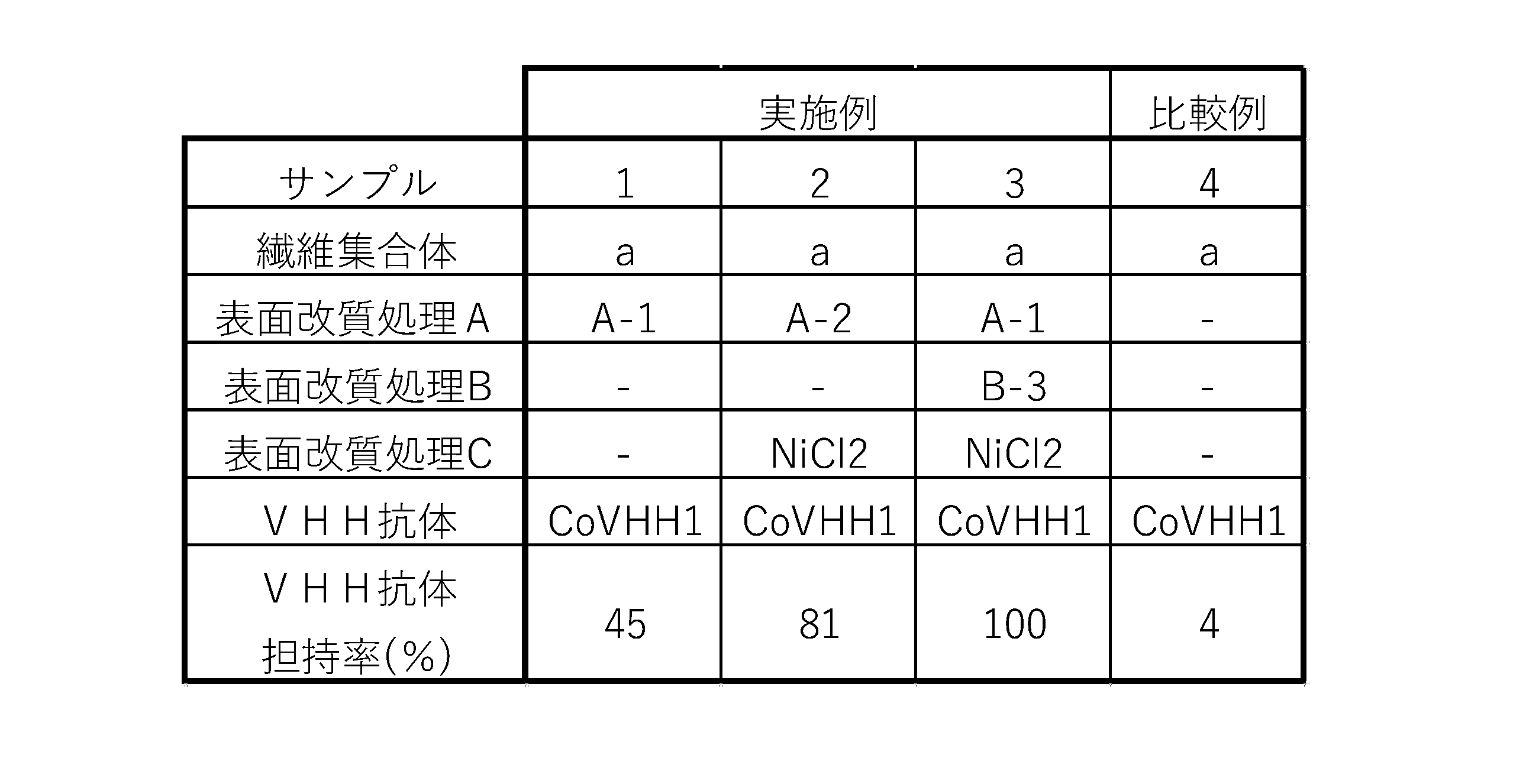
表2に示すように、共重合体(A-1)又は(A-2)による表面改質処理Aを行ったサンプル1~3は、表面改質処理Aを行っていないサンプル4と比較して、多くのCoVHH1が担持されていることがわかった。
<試験例5:抗体担持繊維集合体におけるウイルスの吸着率の検討>
[吸着率の評価]
サンプル1~4を用いて、以下のようにSARS-CoV-2シュードウイルスの吸着率を測定した。
[吸着率の評価]
サンプル1~4を用いて、以下のようにSARS-CoV-2シュードウイルスの吸着率を測定した。
(ウイルス含有溶液への繊維集合体の浸漬)
シリンジ内部にサンプル1~3を入れ、圧縮することで余分な溶液を脱水したのち、各サンプル4枚を1.5mLチューブ(Protein LoBind tube、Eppendorf)に入れ、PBSで10000倍に希釈したSARS-CoV-2シュードウイルス(SARS-CoV-2_S pseudotyped lentivirus(Luciferase)、5.68×10^8 TU/mL、Vector Builder製)溶液を500μL加え、室温でインキュベートした。サンプル4については、サンプル8枚に対して1mLのSARS-CoV-2シュードウイルス溶液を加えた。その後、SARS-CoV-2シュードウイルス溶液を加えてから10分後の溶液の上清を回収した。
シリンジ内部にサンプル1~3を入れ、圧縮することで余分な溶液を脱水したのち、各サンプル4枚を1.5mLチューブ(Protein LoBind tube、Eppendorf)に入れ、PBSで10000倍に希釈したSARS-CoV-2シュードウイルス(SARS-CoV-2_S pseudotyped lentivirus(Luciferase)、5.68×10^8 TU/mL、Vector Builder製)溶液を500μL加え、室温でインキュベートした。サンプル4については、サンプル8枚に対して1mLのSARS-CoV-2シュードウイルス溶液を加えた。その後、SARS-CoV-2シュードウイルス溶液を加えてから10分後の溶液の上清を回収した。
(吸着率の測定)
各サンプルとの接触前後の溶液中のSARS-CoV-2シュードウイルス量を定量することにより、各サンプルのSARS-CoV-2シュードウイルスに対する吸着率を求めた。各溶液中のSARS-CoV-2シュードウイルス量を測定するため、Droplet Digital PCR(ddPCR)を用いて、SARS-CoV-2シュードウイルス内の遺伝子コピー数の定量を行った。ddPCRにはQX200 AutoDG Droplet Digital PCR system(Bio-Rad)を用いた。まず、ドロップレットを作成した。1サンプルあたり11μLのddPCR EvaGreen Supermix(x2)(Bio-Rad)、0.3μLの10μM Forward primer、0.3μLの10μM Reverse primer、9.3μLのNuclease free water、1.1μLのSARS-CoV-2シュードウイルス溶液を混合し、ドロップレット反応液を調製した。プライマーはLuci1F(5'-CGACAAGGATATGGGCTCAC-3':配列番号60)とLuci1R(5'-TTCGCCTCTCTGATTAACGC-3':配列番号61)を用いた。Buffer Controlは、11 μLのddPCR Buffer Control Kit for EvaGreen(x2)(Bio-Rad)、そして11μLのNuclease free waterを混合し調製した。反応液を22μLずつ96wellプレートに添加後、PX1 PCR Plate Sealer(Bio-Rad)を用いて180℃、5秒間の設定でホイルヒートシールによりシーリングし、AutoDG(Bio-Rad)を用いてドロップレットを作製した。全ドロップレットの作製が完了後、30分以内にドロップレットプレートにホイルヒートシールでシーリングした。次のPCRサイクリングは、シーリング後30分以内に実施した。PCRは、ProFlex PCR System(Life technologies)を用いて、95℃で5分間の後、95℃で30秒間と58℃で1分間を40サイクル、その後4℃で5分間、90℃で5分間、4℃でインキュベートの条件で行った。Ramp rateは2℃/秒に設定した。PCR後、ドロップレットプレートをプレートホルダーにセットし、Droplet Reader(Bio-Rad)を用いて陽性および陰性ドロップレットをカウントした。データ解析にはQuantaSoft(Bio-Rad)を用いた。Thresholdは5,000に設定した。
得られた定量値から求められた各サンプルの吸着率は、表3に示す結果となった。この結果から、繊維表面を改質したサンプル1~3のウイルスの吸着率は、未改質のサンプル4に比べて大幅に向上することがわかった。
各サンプルとの接触前後の溶液中のSARS-CoV-2シュードウイルス量を定量することにより、各サンプルのSARS-CoV-2シュードウイルスに対する吸着率を求めた。各溶液中のSARS-CoV-2シュードウイルス量を測定するため、Droplet Digital PCR(ddPCR)を用いて、SARS-CoV-2シュードウイルス内の遺伝子コピー数の定量を行った。ddPCRにはQX200 AutoDG Droplet Digital PCR system(Bio-Rad)を用いた。まず、ドロップレットを作成した。1サンプルあたり11μLのddPCR EvaGreen Supermix(x2)(Bio-Rad)、0.3μLの10μM Forward primer、0.3μLの10μM Reverse primer、9.3μLのNuclease free water、1.1μLのSARS-CoV-2シュードウイルス溶液を混合し、ドロップレット反応液を調製した。プライマーはLuci1F(5'-CGACAAGGATATGGGCTCAC-3':配列番号60)とLuci1R(5'-TTCGCCTCTCTGATTAACGC-3':配列番号61)を用いた。Buffer Controlは、11 μLのddPCR Buffer Control Kit for EvaGreen(x2)(Bio-Rad)、そして11μLのNuclease free waterを混合し調製した。反応液を22μLずつ96wellプレートに添加後、PX1 PCR Plate Sealer(Bio-Rad)を用いて180℃、5秒間の設定でホイルヒートシールによりシーリングし、AutoDG(Bio-Rad)を用いてドロップレットを作製した。全ドロップレットの作製が完了後、30分以内にドロップレットプレートにホイルヒートシールでシーリングした。次のPCRサイクリングは、シーリング後30分以内に実施した。PCRは、ProFlex PCR System(Life technologies)を用いて、95℃で5分間の後、95℃で30秒間と58℃で1分間を40サイクル、その後4℃で5分間、90℃で5分間、4℃でインキュベートの条件で行った。Ramp rateは2℃/秒に設定した。PCR後、ドロップレットプレートをプレートホルダーにセットし、Droplet Reader(Bio-Rad)を用いて陽性および陰性ドロップレットをカウントした。データ解析にはQuantaSoft(Bio-Rad)を用いた。Thresholdは5,000に設定した。
得られた定量値から求められた各サンプルの吸着率は、表3に示す結果となった。この結果から、繊維表面を改質したサンプル1~3のウイルスの吸着率は、未改質のサンプル4に比べて大幅に向上することがわかった。
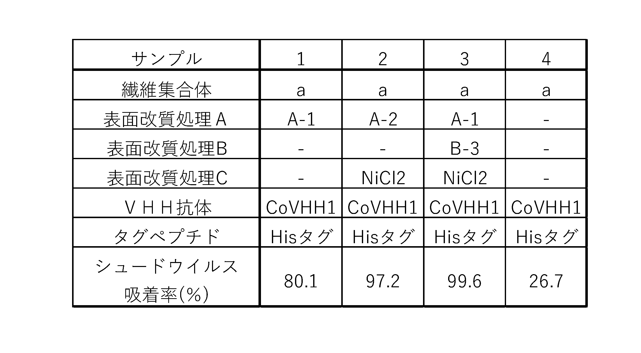
<試験例6:ウイルス濃縮用材料のウイルス濃縮能の検討>
[綿棒状ウイルス濃縮用材料の作製]
ポリプロピレン製からなる棒状の保持部材の一端部に、幅1cm×長さ2cmのシート状の繊維集合体2が保持されたウイルス濃縮用材料aを作製した。繊維集合体2は、保持部材の一端部の表裏を覆うように積層されていた。
[綿棒状ウイルス濃縮用材料の作製]
ポリプロピレン製からなる棒状の保持部材の一端部に、幅1cm×長さ2cmのシート状の繊維集合体2が保持されたウイルス濃縮用材料aを作製した。繊維集合体2は、保持部材の一端部の表裏を覆うように積層されていた。
[ウイルス濃縮用材料の改質処理]
ウイルス濃縮用材料aに対し、共重合体(A-1)による表面改質処理Aを行った。ウイルス濃縮用材料aを1%(w/w)の共重合体(A-1)水溶液(脱イオン水で調整)に浸漬し、室温で60分間撹拌した。処理後の繊維集合体を脱イオン水で洗浄後、キムタオルで脱水した。
表面改質処理Aを行ったウイルス濃縮用材料aを「ウイルス濃縮用材料b」と称する。
[抗体の担持処理]
1mg/mLに調製されたCoVHH-E9溶液にウイルス濃縮用材料bの繊維集合体2部分を浸漬し、4℃で30分静置した。ウイルス濃縮用材料bを取り出し、イオン交換水に浸漬し、室温で10分間静置することで、余分な抗体を洗浄した。
続いて、抗体担持ウイルス濃縮用材料の濡れ性を向上させるため、10%(w/w)DPG(DPG-RF、ADEKA)水溶液に浸漬し、室温で10分間静置した。10%DPG水溶液からウイルス濃縮用材料bを取り出し、33℃恒温槽で1時間風乾させ、抗体担持ウイルス濃縮用材料を作製した。
抗体担持処理を行ったウイルス濃縮用材料bを「ウイルス濃縮用材料c」と称する。
ウイルス濃縮用材料aに対し、共重合体(A-1)による表面改質処理Aを行った。ウイルス濃縮用材料aを1%(w/w)の共重合体(A-1)水溶液(脱イオン水で調整)に浸漬し、室温で60分間撹拌した。処理後の繊維集合体を脱イオン水で洗浄後、キムタオルで脱水した。
表面改質処理Aを行ったウイルス濃縮用材料aを「ウイルス濃縮用材料b」と称する。
[抗体の担持処理]
1mg/mLに調製されたCoVHH-E9溶液にウイルス濃縮用材料bの繊維集合体2部分を浸漬し、4℃で30分静置した。ウイルス濃縮用材料bを取り出し、イオン交換水に浸漬し、室温で10分間静置することで、余分な抗体を洗浄した。
続いて、抗体担持ウイルス濃縮用材料の濡れ性を向上させるため、10%(w/w)DPG(DPG-RF、ADEKA)水溶液に浸漬し、室温で10分間静置した。10%DPG水溶液からウイルス濃縮用材料bを取り出し、33℃恒温槽で1時間風乾させ、抗体担持ウイルス濃縮用材料を作製した。
抗体担持処理を行ったウイルス濃縮用材料bを「ウイルス濃縮用材料c」と称する。
[シュードウイルス吸着試験]
PBSを用いてSARS-CoV-2シュードウイルス溶液を1000倍希釈し、5mLチューブ(Protein LoBind tube、Eppendorf)に1.5mL添加した。
SARS-CoV-2シュードウイルス溶液が添加されたチューブにウイルス濃縮用材料cを1本入れ、濃縮用材料を上下左右に動かすことで溶液を撹拌し、ウイルスを吸着させた。
撹拌を開始してから、5分後の上清を回収した。
PBSを用いてSARS-CoV-2シュードウイルス溶液を1000倍希釈し、5mLチューブ(Protein LoBind tube、Eppendorf)に1.5mL添加した。
SARS-CoV-2シュードウイルス溶液が添加されたチューブにウイルス濃縮用材料cを1本入れ、濃縮用材料を上下左右に動かすことで溶液を撹拌し、ウイルスを吸着させた。
撹拌を開始してから、5分後の上清を回収した。
[吸着率の評価]
SARS-CoV-2シュードウイルスの吸着率は、上清中のSARS-CoV-2シュードウイルス量をもとに、以下の計算式「(初発のウイルス含有溶液中のコピー数-濃縮用材料との接触後の上清中のコピー数)/初発のウイルス含有溶液中のコピー数×100」により算出した。なお、「初発のウイルス含有溶液」とは、ウイルス濃縮用材料サンプルとの接触前のウイルス含有溶液を意味する。
SARS-CoV-2シュードウイルス溶液中の上清におけるSARS-CoV-2シュードウイルス量を測定するため、ddPCRを行った。
ddPCRは、試験例5と同様の手順で実施した。
初発サンプルと接触後の上清中のシュードウイルス量の定量値は、図20に示す結果となった。定量値から算出された吸着率は、97.4%となり、綿棒状ウイルス濃縮用材料においても十分なウイルス吸着性能を示すことが分かった。
SARS-CoV-2シュードウイルスの吸着率は、上清中のSARS-CoV-2シュードウイルス量をもとに、以下の計算式「(初発のウイルス含有溶液中のコピー数-濃縮用材料との接触後の上清中のコピー数)/初発のウイルス含有溶液中のコピー数×100」により算出した。なお、「初発のウイルス含有溶液」とは、ウイルス濃縮用材料サンプルとの接触前のウイルス含有溶液を意味する。
SARS-CoV-2シュードウイルス溶液中の上清におけるSARS-CoV-2シュードウイルス量を測定するため、ddPCRを行った。
ddPCRは、試験例5と同様の手順で実施した。
初発サンプルと接触後の上清中のシュードウイルス量の定量値は、図20に示す結果となった。定量値から算出された吸着率は、97.4%となり、綿棒状ウイルス濃縮用材料においても十分なウイルス吸着性能を示すことが分かった。
<試験例7:ウイルス濃縮用材料の唾液サンプル中の濃縮能の検討>
[綿棒状ウイルス濃縮用材料の作製]
ポリプロピレン製からなる棒状の保持部材の一端部に、幅1cm×長さ2cmのシート状の繊維集合体2が保持されたウイルス濃縮用材料aを作製した。繊維集合体2は、保持部材の一端部の表裏を覆うように積層されていた。
[綿棒状ウイルス濃縮用材料の作製]
ポリプロピレン製からなる棒状の保持部材の一端部に、幅1cm×長さ2cmのシート状の繊維集合体2が保持されたウイルス濃縮用材料aを作製した。繊維集合体2は、保持部材の一端部の表裏を覆うように積層されていた。
[ウイルス濃縮用材料の改質処理]
ウイルス濃縮用材料aに対し、試験例6と同様に共重合体(A-1)による表面改質処理Aと抗体担持処理を行い、ウイルス濃縮用材料cを調製した。
ウイルス濃縮用材料aに対し、試験例6と同様に共重合体(A-1)による表面改質処理Aと抗体担持処理を行い、ウイルス濃縮用材料cを調製した。
[シュードウイルス吸着試験]
採取した唾液に0.5M EDTA pH8.0(株式会社ニッポンジーン製)を1/10量添加し、終濃度50mMのEDTAを含む唾液溶液を調製した。EDTAを添加しない唾液溶液には、イオン交換水を同量添加した。
EDTAを添加した条件を条件1、EDTAを添加していない条件を条件2とした。
調製した唾液溶液を用いてSARS-CoV-2シュードウイルス溶液を1000倍希釈し、15mL遠沈管(Protein LoBind tube、Eppendorf)に1.5mL添加した。SARS-CoV-2シュードウイルス溶液が添加された遠沈管にウイルス濃縮用材料cを1本入れ、濃縮用材料を上下左右に動かすことで溶液を撹拌し、ウイルスを吸着させた。
撹拌を開始してから、1分後、5分後、10分後の上清を回収した。
[吸着率の評価]
SARS-CoV-2シュードウイルスの吸着率は、上清中のSARS-CoV-2シュードウイルス量をもとに、以下の計算式「(初発のウイルス含有溶液中のコピー数-濃縮用材料との接触後の上清中のコピー数)/初発のウイルス含有溶液中のコピー数×100」により算出した。
唾液懸濁SARS-CoV-2シュードウイルス溶液中の上清におけるSARS-CoV-2シュードウイルス量を測定するため、ddPCRを行った。ddPCRは、試験例5と同様の手順で実施した。
得られた定量値をもとに算出されたウイルス濃縮用材料の吸着率は、図21に示すとおりになった。
EDTAを添加していない条件2では、ウイルス濃縮用材料を接触させてから10分後においてもウイルスの濃縮がほとんど確認されなかったのに対し、EDTAを添加した条件1では10分の接触後に50%以上の高い吸着率を示し、EDTAの添加により唾液中のウイルス濃縮能が大幅に向上することが分かった。
採取した唾液に0.5M EDTA pH8.0(株式会社ニッポンジーン製)を1/10量添加し、終濃度50mMのEDTAを含む唾液溶液を調製した。EDTAを添加しない唾液溶液には、イオン交換水を同量添加した。
EDTAを添加した条件を条件1、EDTAを添加していない条件を条件2とした。
調製した唾液溶液を用いてSARS-CoV-2シュードウイルス溶液を1000倍希釈し、15mL遠沈管(Protein LoBind tube、Eppendorf)に1.5mL添加した。SARS-CoV-2シュードウイルス溶液が添加された遠沈管にウイルス濃縮用材料cを1本入れ、濃縮用材料を上下左右に動かすことで溶液を撹拌し、ウイルスを吸着させた。
撹拌を開始してから、1分後、5分後、10分後の上清を回収した。
[吸着率の評価]
SARS-CoV-2シュードウイルスの吸着率は、上清中のSARS-CoV-2シュードウイルス量をもとに、以下の計算式「(初発のウイルス含有溶液中のコピー数-濃縮用材料との接触後の上清中のコピー数)/初発のウイルス含有溶液中のコピー数×100」により算出した。
唾液懸濁SARS-CoV-2シュードウイルス溶液中の上清におけるSARS-CoV-2シュードウイルス量を測定するため、ddPCRを行った。ddPCRは、試験例5と同様の手順で実施した。
得られた定量値をもとに算出されたウイルス濃縮用材料の吸着率は、図21に示すとおりになった。
EDTAを添加していない条件2では、ウイルス濃縮用材料を接触させてから10分後においてもウイルスの濃縮がほとんど確認されなかったのに対し、EDTAを添加した条件1では10分の接触後に50%以上の高い吸着率を示し、EDTAの添加により唾液中のウイルス濃縮能が大幅に向上することが分かった。
<試験例8:ウイルス濃縮用材料の唾液サンプル中の新型コロナウイルス濃縮能の検討>
ウイルス濃縮用材料を作製し、唾液サンプル中のSARS-CoV-2ウイルスに対する濃縮能について評価した。
ウイルス濃縮用材料を作製し、唾液サンプル中のSARS-CoV-2ウイルスに対する濃縮能について評価した。
[綿棒状ウイルス濃縮用材料の改質処理]
試験例6と同様にして、0.5mm幅の棒(ポリプロピレン製)からなる保持部材の一端部に、幅1cm×長さ2cmのシート状の繊維集合体2が保持されたウイルス濃縮用材料aを作製し、表面改質処理及び抗体担持処理を行うことで、ウイルス濃縮用材料cを作製した。
試験例6と同様にして、0.5mm幅の棒(ポリプロピレン製)からなる保持部材の一端部に、幅1cm×長さ2cmのシート状の繊維集合体2が保持されたウイルス濃縮用材料aを作製し、表面改質処理及び抗体担持処理を行うことで、ウイルス濃縮用材料cを作製した。
[新型コロナウイルス濃縮試験]
採取した唾液に0.5M EDTA pH8.0(株式会社ニッポンジーン製)を1/10量添加し、終濃度50mMのEDTAを含む唾液溶液を調製した。
唾液溶液3465μLに北里大学より提供を受けたSARS-CoV-2溶液(KUH003株、2.33×10^10 RNA copies/mL)35μLを加え、2.33x10^8 copies/mLの唾液懸濁SARS-CoV-2溶液を調製した。
唾液懸濁SARS-CoV-2溶液1.5mLを15mL遠沈管(Protein LoBind tube、Eppendorf)に添加し、ウイルス濃縮用材料cを入れて上下左右に動かすことで溶液を撹拌し、ウイルスと接触させた。撹拌を開始してから10分後にウイルス濃縮用材料cを引き上げ、上清を回収した。
採取した唾液に0.5M EDTA pH8.0(株式会社ニッポンジーン製)を1/10量添加し、終濃度50mMのEDTAを含む唾液溶液を調製した。
唾液溶液3465μLに北里大学より提供を受けたSARS-CoV-2溶液(KUH003株、2.33×10^10 RNA copies/mL)35μLを加え、2.33x10^8 copies/mLの唾液懸濁SARS-CoV-2溶液を調製した。
唾液懸濁SARS-CoV-2溶液1.5mLを15mL遠沈管(Protein LoBind tube、Eppendorf)に添加し、ウイルス濃縮用材料cを入れて上下左右に動かすことで溶液を撹拌し、ウイルスと接触させた。撹拌を開始してから10分後にウイルス濃縮用材料cを引き上げ、上清を回収した。
[吸着率の評価]
(ウエスタンブロッティング)
上清中のSARS-CoV-2のNタンパク質の量を測定するため、抗Nタンパク質抗体を用いたウエスタンブロッティングを実施した。
回収した上清130μLと、10×Sample Reducing Agent(Invitrogen)20μLと、4×LDS Sample Buffer(Invitrogen)50μLとを混合し、100℃で5分間加熱した。
標準コントロールとして、組み換えNタンパク質(SARS-CoV Nucleoprotein/NP Protein(His Tag)、Sino Biological)を用いた。組み換えNタンパク質は、サンプル10μLあたりにそれぞれ40ng、20ng、10ngが含まれるように調製し、100℃で5分間加熱した。加熱処理したサンプル10μLを10%,Bis-Tris,1.0mm,Mini Protein Gel(Invitrogen)にアプライし、200Vで40分間電気泳動した。電気泳動終了後、ゲルを取り出し、iBlot2(Invitrogen)を用いて、PVDFメンブレンへタンパク質転写した。続いて、メンブレンを取り出し、iBind(Invitrogen)を用いて、抗原抗体反応を行った。操作は付属のプロトコールに従った。1次抗体には1000倍希釈したSARS-CoV-2 Nucleocapsid Antibody Rabbit Mab(SinoBiological,40143-R019)を用い、2次抗体には1000倍希釈したAnti-Rabbit IgG HRP-linked Antibody(CST,7074S)を使用した。
抗原抗体反応終了後、メンブレンをイオン交換水で2回洗浄し、2mLのECL Prime Western Blotting Detection Reagent(Cytiva)をメンブレンに滴下して、室温で5分間インキュベートした。メンブレンから余計な溶液を除去し、CCDカメラ付きイメージャー(Light capture II、ATTO)で化学発光を検出した。
(バンド強度の解析)
取得した画像から、画像解析ソフトウェア(Image Analysis Software CS Analyzer 4、ATTO)を用いて、各サンプルのNタンパク質のバンド強度を数値化した。各サンプルのバンド強度値は、表4に示すとおりになった。
(ウエスタンブロッティング)
上清中のSARS-CoV-2のNタンパク質の量を測定するため、抗Nタンパク質抗体を用いたウエスタンブロッティングを実施した。
回収した上清130μLと、10×Sample Reducing Agent(Invitrogen)20μLと、4×LDS Sample Buffer(Invitrogen)50μLとを混合し、100℃で5分間加熱した。
標準コントロールとして、組み換えNタンパク質(SARS-CoV Nucleoprotein/NP Protein(His Tag)、Sino Biological)を用いた。組み換えNタンパク質は、サンプル10μLあたりにそれぞれ40ng、20ng、10ngが含まれるように調製し、100℃で5分間加熱した。加熱処理したサンプル10μLを10%,Bis-Tris,1.0mm,Mini Protein Gel(Invitrogen)にアプライし、200Vで40分間電気泳動した。電気泳動終了後、ゲルを取り出し、iBlot2(Invitrogen)を用いて、PVDFメンブレンへタンパク質転写した。続いて、メンブレンを取り出し、iBind(Invitrogen)を用いて、抗原抗体反応を行った。操作は付属のプロトコールに従った。1次抗体には1000倍希釈したSARS-CoV-2 Nucleocapsid Antibody Rabbit Mab(SinoBiological,40143-R019)を用い、2次抗体には1000倍希釈したAnti-Rabbit IgG HRP-linked Antibody(CST,7074S)を使用した。
抗原抗体反応終了後、メンブレンをイオン交換水で2回洗浄し、2mLのECL Prime Western Blotting Detection Reagent(Cytiva)をメンブレンに滴下して、室温で5分間インキュベートした。メンブレンから余計な溶液を除去し、CCDカメラ付きイメージャー(Light capture II、ATTO)で化学発光を検出した。
(バンド強度の解析)
取得した画像から、画像解析ソフトウェア(Image Analysis Software CS Analyzer 4、ATTO)を用いて、各サンプルのNタンパク質のバンド強度を数値化した。各サンプルのバンド強度値は、表4に示すとおりになった。
(吸着率の算出)
SARS-CoV-2ウイルスの吸着率は、バンド強度から求めた上清サンプル中のNタンパク質量をもとに、以下の計算式「(初発のウイルス含有溶液中のNタンパク質量-濃縮用材料との接触後の上清中のNタンパク質量)/初発のウイルス含有溶液中のNタンパク質量×100」により算出した。
バンド強度値と組み換えNタンパク質量をプロットしたグラフから、検量線を作成した。プロット図及び検量線を図22に示す。
得られた検量線を用いて、ウイルス濃縮用材料接触前と接触後の上清サンプルのNタンパク質量を算出すると、図23に示す通り、ウイルス濃縮用材料接触前後で39.0ngから22.1ngに減少したことが分かった。この値をもとに算出した吸着率は43.3%であり、ウイルス濃縮用材料cは唾液中に含まれるSARS-CoV-2ウイルス粒子を濃縮可能であることが分かった。
SARS-CoV-2ウイルスの吸着率は、バンド強度から求めた上清サンプル中のNタンパク質量をもとに、以下の計算式「(初発のウイルス含有溶液中のNタンパク質量-濃縮用材料との接触後の上清中のNタンパク質量)/初発のウイルス含有溶液中のNタンパク質量×100」により算出した。
バンド強度値と組み換えNタンパク質量をプロットしたグラフから、検量線を作成した。プロット図及び検量線を図22に示す。
得られた検量線を用いて、ウイルス濃縮用材料接触前と接触後の上清サンプルのNタンパク質量を算出すると、図23に示す通り、ウイルス濃縮用材料接触前後で39.0ngから22.1ngに減少したことが分かった。この値をもとに算出した吸着率は43.3%であり、ウイルス濃縮用材料cは唾液中に含まれるSARS-CoV-2ウイルス粒子を濃縮可能であることが分かった。
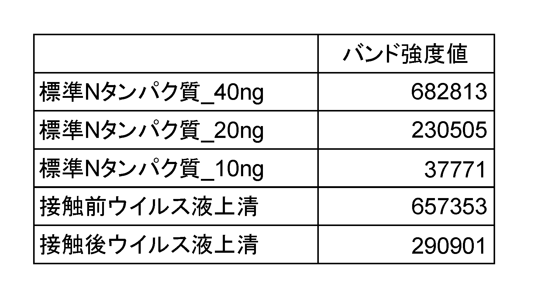
<試験例9:唾液サンプル中のウイルス濃縮能に対するキレート剤添加効果の検討>
抗体担持繊維集合体サンプルを作製し、唾液サンプル中のSARS-CoV-2シュードウイルスに対する濃縮能について評価した。
抗体担持繊維集合体サンプルを作製し、唾液サンプル中のSARS-CoV-2シュードウイルスに対する濃縮能について評価した。
[繊維集合体の改質処理]
繊維集合体2に対し、共重合体(A-1)による表面改質処理Aを行った。繊維集合体2を1%の共重合体(A-1)水溶液(脱イオン水で調整)に浸漬し、室温で60分間撹拌した。処理後の繊維集合体2を脱イオン水で洗浄後、キムタオルで脱水した。
この表面改質処理Aを行った繊維集合体2を「繊維集合体サンプルe」と称する。
[抗体の担持処理]
繊維集合体サンプルeを、1cm×2cm角の長方形状に切断したものに対し、以下の抗体担持処理を行い、抗体担持繊維集合体サンプル5を作製した。
1mg/mLに調製されたCoVHH-E9溶液400μLに、繊維集合体サンプルeを浸漬し、4℃で一晩静置した。繊維集合体サンプルeを取り出し、イオン交換水に浸漬し、室温で10分間静置することで、余分な抗体を洗浄した。続いて、抗体担持繊維集合体の濡れ性を向上させるため、10%(w/w)DPG(ADEKA製、DPG-RF)水溶液に浸漬し、室温で10分間静置した。10%DPG水溶液から繊維集合体サンプルeを取り出し、33℃恒温槽で1時間風乾させ、抗体担持繊維集合体サンプル5を作製した。
繊維集合体2に対し、共重合体(A-1)による表面改質処理Aを行った。繊維集合体2を1%の共重合体(A-1)水溶液(脱イオン水で調整)に浸漬し、室温で60分間撹拌した。処理後の繊維集合体2を脱イオン水で洗浄後、キムタオルで脱水した。
この表面改質処理Aを行った繊維集合体2を「繊維集合体サンプルe」と称する。
[抗体の担持処理]
繊維集合体サンプルeを、1cm×2cm角の長方形状に切断したものに対し、以下の抗体担持処理を行い、抗体担持繊維集合体サンプル5を作製した。
1mg/mLに調製されたCoVHH-E9溶液400μLに、繊維集合体サンプルeを浸漬し、4℃で一晩静置した。繊維集合体サンプルeを取り出し、イオン交換水に浸漬し、室温で10分間静置することで、余分な抗体を洗浄した。続いて、抗体担持繊維集合体の濡れ性を向上させるため、10%(w/w)DPG(ADEKA製、DPG-RF)水溶液に浸漬し、室温で10分間静置した。10%DPG水溶液から繊維集合体サンプルeを取り出し、33℃恒温槽で1時間風乾させ、抗体担持繊維集合体サンプル5を作製した。
[シュードウイルス吸着試験]
採取した唾液に0.5M EDTA pH8.0(ニッポンジーン)とSARS-CoV-2シュードウイルスを混合し、唾液懸濁SARS-CoV-2シュードウイルス溶液を調製した。EDTAの終濃度が50mMのものを条件3、5mMのものを条件4、0.5mMのものを条件5とした。ネガティブコントロールとして、イオン交換水を条件3と同量添加したものを用意し、条件6とした。
繊維集合体サンプル5を2mLチューブ(Protein LoBind tube、Eppendorf)に入れた。繊維集合体サンプル5が入った2mLチューブに各唾液懸濁SARS-CoV-2シュードウイルス溶液1.5mLを加え、インテリミキサー(TOHO)を用いて室温で転倒混和した。その後、唾液懸濁SARS-CoV-2シュードウイルス溶液を加えてから10分後の溶液の上清を回収した。
採取した唾液に0.5M EDTA pH8.0(ニッポンジーン)とSARS-CoV-2シュードウイルスを混合し、唾液懸濁SARS-CoV-2シュードウイルス溶液を調製した。EDTAの終濃度が50mMのものを条件3、5mMのものを条件4、0.5mMのものを条件5とした。ネガティブコントロールとして、イオン交換水を条件3と同量添加したものを用意し、条件6とした。
繊維集合体サンプル5を2mLチューブ(Protein LoBind tube、Eppendorf)に入れた。繊維集合体サンプル5が入った2mLチューブに各唾液懸濁SARS-CoV-2シュードウイルス溶液1.5mLを加え、インテリミキサー(TOHO)を用いて室温で転倒混和した。その後、唾液懸濁SARS-CoV-2シュードウイルス溶液を加えてから10分後の溶液の上清を回収した。
[吸着率の評価]
SARS-CoV-2シュードウイルスの吸着率は、試験例5と同様にddPCRにより定量したSARS-CoV-2シュードウイルス量を用いて算出した。
得られた定量値をもとに算出されたウイルス濃縮用材料の吸着率は、図24に示すとおりになった。
EDTAの濃度依存的なSARS-CoV-2シュードウイルスの吸着率の増加が確認され、唾液サンプルに対しEDTAを0.5mM以上となるように添加することにより、唾液中ウイルスの濃縮能が向上することがわかった。
SARS-CoV-2シュードウイルスの吸着率は、試験例5と同様にddPCRにより定量したSARS-CoV-2シュードウイルス量を用いて算出した。
得られた定量値をもとに算出されたウイルス濃縮用材料の吸着率は、図24に示すとおりになった。
EDTAの濃度依存的なSARS-CoV-2シュードウイルスの吸着率の増加が確認され、唾液サンプルに対しEDTAを0.5mM以上となるように添加することにより、唾液中ウイルスの濃縮能が向上することがわかった。
1…ウイルス濃縮用材料
2…繊維集合体
3…抗体
F…繊維
2…繊維集合体
3…抗体
F…繊維
本発明のウイルス濃縮用材料等によれば、ウイルスを簡便に濃縮し、検出感度を高めることが可能である。
Claims (20)
- 繊維を有する繊維集合体と、
前記繊維の表面に担持された、標的ウイルスに対する抗体と、
を備え、
前記繊維のメジアン繊維径は、20μm未満であり、
前記繊維の表面は、両親媒性を有するアニオン性又はカチオン性重合体の1種以上によって改質されている
ウイルス濃縮用材料。 - 前記繊維のメジアン繊維径は、1μm以下である
請求項1に記載のウイルス濃縮用材料。 - 前記繊維集合体の比表面積は、1m2/g以上である
請求項1又は2に記載のウイルス濃縮用材料。 - 前記繊維集合体は、前記繊維の基材として、熱可塑性樹脂を含む
請求項1から3のいずれか一項に記載のウイルス濃縮用材料。 - 前記熱可塑性樹脂は、ポリオレフィン樹脂を含む
請求項4に記載のウイルス濃縮用材料。 - 前記熱可塑性樹脂は、ポリプロピレンを含む
請求項5に記載のウイルス濃縮用材料。 - 前記抗体は、タグペプチドを介して前記繊維の表面に配置されている
請求項1から6のいずれか一項に記載のウイルス濃縮用材料。 - 前記タグペプチドは、前記抗体のC末端に結合している
請求項7に記載のウイルス濃縮用材料。 - 前記タグペプチドは、配列番号1~16で示されるアミノ酸配列から選ばれる1種又は2種以上のアミノ酸配列を含む
請求項8に記載のウイルス濃縮用材料。 - 前記抗体が担持された前記繊維集合体の1g当たりにおける前記抗体の含有量は、1mg/g以上である
請求項1から9のいずれか一項に記載のウイルス濃縮用材料。 - 前記抗体は、IgG抗体、重鎖抗体、及びフラグメント抗体から選ばれる1種又は2種以上である
請求項1から10のいずれか一項に記載のウイルス濃縮用材料。 - 前記抗体は、VHH抗体である
請求項11に記載のウイルス濃縮用材料。 - 前記標的ウイルスは、ヒト及び家畜への感染が報告されている病原性のウイルスである
請求項1から12のいずれか一項に記載のウイルス濃縮用材料。 - 繊維を有する繊維集合体と、前記繊維の表面に担持された標的ウイルスに対する抗体と、を有するウイルス濃縮用材料と、
前記標的ウイルスの検査のための検査対象液を収容可能であり、前記繊維集合体の挿入及び取り出しが可能な容器と、
を備え、
前記繊維のメジアン繊維径は、20μm未満であり、
前記繊維の表面は、両親媒性を有するアニオン性又はカチオン性重合体の1種以上によって改質されている
ウイルス濃縮キット。 - 繊維を有する繊維集合体と、前記繊維の表面に担持された標的ウイルスに対する抗体と、を有するウイルス濃縮用材料と、
前記標的ウイルスの検査のための検査対象液を収容可能であり、前記繊維集合体の挿入及び取り出しが可能な容器と、
前記繊維集合体に付着した前記検査対象液を用いて前記標的ウイルスを検出するための検査試薬と、
を備え、
前記繊維のメジアン繊維径は、20μm未満であり、
前記繊維の表面は、両親媒性を有するアニオン性又はカチオン性重合体の1種以上によって改質されている
ウイルス検査キット。 - 繊維を有する繊維集合体と、前記繊維の表面に担持された標的ウイルスに対する抗体と、を有し、前記繊維のメジアン繊維径が20μm未満であり、かつ、前記繊維の表面が、両親媒性を有するアニオン性又はカチオン性重合体の1種以上によって改質されている、ウイルス濃縮用材料を準備し、
前記繊維集合体を、前記標的ウイルスの検査のための検査対象液と接触させることで、前記検査対象液中の前記標的ウイルスを濃縮する
ウイルス濃縮方法。 - 前記検査対象液が、唾液を含む
請求項16に記載のウイルス濃縮方法。 - 前記濃縮工程前に、前記検査対象液にキレート剤を添加する
請求項17に記載のウイルス濃縮方法。 - 繊維を有する繊維集合体と、前記繊維の表面に担持された標的ウイルスに対する抗体と、を有し、前記繊維のメジアン繊維径が20μm未満であり、かつ、前記繊維の表面が、両親媒性を有するアニオン性又はカチオン性重合体の1種以上によって改質されている、ウイルス濃縮用材料を準備し、
前記繊維集合体を、前記標的ウイルスの検査のための検査対象液と接触させることで、前記検査対象液中の前記標的ウイルスを濃縮し、
濃縮された前記標的ウイルスを検出する
ウイルス検査方法。 - メジアン繊維径が20μm未満である繊維を有する繊維集合体を形成し、
前記繊維の表面を、両親媒性を有するアニオン性又はカチオン性重合体の1種以上によって改質し、
標的ウイルスに対する抗体に、前記繊維集合体を接触させることで、前記繊維の表面に前記抗体を担持させる
ウイルス濃縮用材料の製造方法。
Applications Claiming Priority (4)
| Application Number | Priority Date | Filing Date | Title |
|---|---|---|---|
| JP2021-009175 | 2021-01-22 | ||
| JP2021009175 | 2021-01-22 | ||
| JP2021142114A JP2022113098A (ja) | 2021-01-22 | 2021-09-01 | ウイルス濃縮用材料 |
| JP2021-142114 | 2021-09-01 |
Publications (1)
| Publication Number | Publication Date |
|---|---|
| WO2022158505A1 true WO2022158505A1 (ja) | 2022-07-28 |
Family
ID=82549474
Family Applications (1)
| Application Number | Title | Priority Date | Filing Date |
|---|---|---|---|
| PCT/JP2022/001883 Ceased WO2022158505A1 (ja) | 2021-01-22 | 2022-01-20 | ウイルス濃縮用材料 |
Country Status (1)
| Country | Link |
|---|---|
| WO (1) | WO2022158505A1 (ja) |
Citations (6)
| Publication number | Priority date | Publication date | Assignee | Title |
|---|---|---|---|---|
| JP2002105434A (ja) * | 2000-10-02 | 2002-04-10 | Lion Corp | 両性両親媒性表面処理剤 |
| US20070264720A1 (en) * | 2005-12-15 | 2007-11-15 | Cunningham Scott D | Polypropylene binding peptides and methods of use |
| JP2009545642A (ja) * | 2006-08-03 | 2009-12-24 | チバ ホールディング インコーポレーテッド | 表面の湿潤性を改良するための組成物 |
| JP2014133784A (ja) * | 2013-01-08 | 2014-07-24 | Kao Corp | 親水化処理剤及び親水化処理方法 |
| WO2017188346A1 (ja) * | 2016-04-27 | 2017-11-02 | 国立大学法人 東京大学 | マイクロファイバーを用いた血中循環細胞の捕捉及び回収用材料及び当該材料を用いる方法 |
| JP2020105458A (ja) * | 2018-12-28 | 2020-07-09 | 花王株式会社 | 溶融電界紡糸用組成物、並びに繊維及びその製造方法 |
-
2022
- 2022-01-20 WO PCT/JP2022/001883 patent/WO2022158505A1/ja not_active Ceased
Patent Citations (6)
| Publication number | Priority date | Publication date | Assignee | Title |
|---|---|---|---|---|
| JP2002105434A (ja) * | 2000-10-02 | 2002-04-10 | Lion Corp | 両性両親媒性表面処理剤 |
| US20070264720A1 (en) * | 2005-12-15 | 2007-11-15 | Cunningham Scott D | Polypropylene binding peptides and methods of use |
| JP2009545642A (ja) * | 2006-08-03 | 2009-12-24 | チバ ホールディング インコーポレーテッド | 表面の湿潤性を改良するための組成物 |
| JP2014133784A (ja) * | 2013-01-08 | 2014-07-24 | Kao Corp | 親水化処理剤及び親水化処理方法 |
| WO2017188346A1 (ja) * | 2016-04-27 | 2017-11-02 | 国立大学法人 東京大学 | マイクロファイバーを用いた血中循環細胞の捕捉及び回収用材料及び当該材料を用いる方法 |
| JP2020105458A (ja) * | 2018-12-28 | 2020-07-09 | 花王株式会社 | 溶融電界紡糸用組成物、並びに繊維及びその製造方法 |
Non-Patent Citations (4)
| Title |
|---|
| HOY CARLTON F.O., KUSHIRO KEIICHIRO, YAMAOKA YUTARO, RYO AKIHIDE, TAKAI MADOKA: "Rapid multiplex microfiber-based immunoassay for anti-MERS-CoV antibody detection", SENSING AND BIO-SENSING RESEARCH, vol. 26, 1 November 2019 (2019-11-01), pages 1 - 7, XP055952861, ISSN: 2214-1804, DOI: 10.1016/j.sbsr.2019.100304 * |
| JUDS CARMEN, SCHMIDT JOHANNES, WELLER MICHAEL G., LANGE THORID, BECK UWE, CONRAD TIM, BÖRNER HANS G.: "Combining Phage Display and Next-Generation Sequencing for Materials Sciences: A Case Study on Probing Polypropylene Surfaces", JOURNAL OF THE AMERICAN CHEMICAL SOCIETY, vol. 142, no. 24, 17 June 2020 (2020-06-17), pages 10624 - 10628, XP055952862, ISSN: 0002-7863, DOI: 10.1021/jacs.0c03482 * |
| KATAYAMA KAZUHIKO: "A research group led by Prof. Kazuhiko Katayama at the Ōmura Satoshi Memorial Institute of Kitasato University has discovered SARS-Coronavirus-2 neutralizing VHH antibodies with therapeutic potential against COVID-19", EPSILON MOLECULAR ENGINEERING, INC - PRESS REALES, 7 May 2020 (2020-05-07), pages 1 - 5, XP055952866 * |
| KONDO T, IWATANI Y, K, FUJINO T, UMEMOTO S, YOKOMAKU Y, ISHIZAKI K, KITO S, SEZAKI T, HAYASHI G, MURAKAMI H: "Antibody-like proteins that capture and neutralize SARS-CoV-2", SCIENCE ADVANCES, vol. 6, no. 42, 14 October 2020 (2020-10-14), pages 1 - 13, XP055875242, DOI: 10.1126/sciadv.abd3916 * |
Similar Documents
| Publication | Publication Date | Title |
|---|---|---|
| CN105283761B (zh) | 免疫层析诊断试剂盒 | |
| JP5046050B2 (ja) | 医療材料用高分子化合物及び該高分子化合物を用いたバイオチップ用基板 | |
| CN105548538A (zh) | 柯萨奇病毒A16和肠道病毒71的IgM抗体联合检测装置及制法 | |
| Cross et al. | Protein-surface interactions on stimuli-responsive polymeric biomaterials | |
| JP5597190B2 (ja) | 高病原性鳥インフルエンザh5n1亜型ウイルスの検出キット | |
| US20140120558A1 (en) | Detecting Cells Secreting A Protein Of Interest | |
| JP2016503486A (ja) | リガンドグラフト化基材 | |
| WO2017200008A1 (ja) | ジカウイルス検出用免疫クロマト分析装置 | |
| JP6143818B2 (ja) | マイコプラズマ・ニューモニエ検出用免疫クロマト分析装置 | |
| JP2020500948A (ja) | 官能化コポリマー及びその使用 | |
| WO2022158505A1 (ja) | ウイルス濃縮用材料 | |
| JP2022113098A (ja) | ウイルス濃縮用材料 | |
| JP2022113059A (ja) | ウイルス濃縮用材料 | |
| TW201817492A (zh) | 捕捉或分離白血球的聚合物、裝置、其製造方法及其應用 | |
| WO2019156248A1 (ja) | チクングニアウイルス検出用免疫クロマト分析装置 | |
| WO2021221050A1 (ja) | 構造物及びその製造方法、それを用いた吸着体、並びに生体粒子の精製方法 | |
| JP2022109167A (ja) | ウイルス濃縮用材料 | |
| JP2022109143A (ja) | ウイルス濃縮用材料 | |
| JP2022162385A (ja) | ウイルス吸着材 | |
| JP2022109171A (ja) | ウイルス濃縮用材料 | |
| JP4434971B2 (ja) | 捕捉ビーズ用マイクロ粒子およびそれを用いた捕捉ビーズならびにバイオチップ | |
| TWI816680B (zh) | 經細胞之選擇性分離用或細胞培養用聚合物被覆的基體 | |
| Serafim et al. | Electrospinning induced surface activation (EISA) of highly porous PMMA microfiber mats for HIV diagnosis | |
| JP2023023973A (ja) | ウイルス吸着材 | |
| TWI254035B (en) | A process for the preparation of a nitrocellulose thin film |
Legal Events
| Date | Code | Title | Description |
|---|---|---|---|
| 121 | Ep: the epo has been informed by wipo that ep was designated in this application |
Ref document number: 22742627 Country of ref document: EP Kind code of ref document: A1 |
|
| NENP | Non-entry into the national phase |
Ref country code: DE |
|
| 122 | Ep: pct application non-entry in european phase |
Ref document number: 22742627 Country of ref document: EP Kind code of ref document: A1 |