WO2022158266A1 - フェンダーライナー及びその製造方法 - Google Patents
フェンダーライナー及びその製造方法 Download PDFInfo
- Publication number
- WO2022158266A1 WO2022158266A1 PCT/JP2021/048512 JP2021048512W WO2022158266A1 WO 2022158266 A1 WO2022158266 A1 WO 2022158266A1 JP 2021048512 W JP2021048512 W JP 2021048512W WO 2022158266 A1 WO2022158266 A1 WO 2022158266A1
- Authority
- WO
- WIPO (PCT)
- Prior art keywords
- foam
- nonwoven fabric
- fender liner
- tire
- layer
- Prior art date
- Legal status (The legal status is an assumption and is not a legal conclusion. Google has not performed a legal analysis and makes no representation as to the accuracy of the status listed.)
- Ceased
Links
Images




Classifications
-
- B—PERFORMING OPERATIONS; TRANSPORTING
- B32—LAYERED PRODUCTS
- B32B—LAYERED PRODUCTS, i.e. PRODUCTS BUILT-UP OF STRATA OF FLAT OR NON-FLAT, e.g. CELLULAR OR HONEYCOMB, FORM
- B32B5/00—Layered products characterised by the non- homogeneity or physical structure, i.e. comprising a fibrous, filamentary, particulate or foam layer; Layered products characterised by having a layer differing constitutionally or physically in different parts
- B32B5/22—Layered products characterised by the non- homogeneity or physical structure, i.e. comprising a fibrous, filamentary, particulate or foam layer; Layered products characterised by having a layer differing constitutionally or physically in different parts characterised by the presence of two or more layers which are next to each other and are fibrous, filamentary, formed of particles or foamed
- B32B5/24—Layered products characterised by the non- homogeneity or physical structure, i.e. comprising a fibrous, filamentary, particulate or foam layer; Layered products characterised by having a layer differing constitutionally or physically in different parts characterised by the presence of two or more layers which are next to each other and are fibrous, filamentary, formed of particles or foamed one layer being a fibrous or filamentary layer
-
- B—PERFORMING OPERATIONS; TRANSPORTING
- B62—LAND VEHICLES FOR TRAVELLING OTHERWISE THAN ON RAILS
- B62D—MOTOR VEHICLES; TRAILERS
- B62D25/00—Superstructure or monocoque structure sub-units; Parts or details thereof not otherwise provided for
- B62D25/08—Front or rear portions
- B62D25/16—Mud-guards or wings; Wheel cover panels
- B62D25/18—Parts or details thereof, e.g. mudguard flaps
Definitions
- the present disclosure relates to a fender liner and a manufacturing method thereof.
- the automobile interior and exterior material described in Patent Document 1 is integrated with the base material formed in a predetermined shape by insert molding using foamed resin at predetermined locations on one surface of the base material facing the vehicle body. and a foam that is formed into a predetermined shape.
- the base material is formed of nonwoven fabric or the like.
- Patent Document 1 The foam described in Patent Document 1 is integrated with the nonwoven fabric by insert molding using foamed resin. Since the nonwoven fabric and the foam are integrated, it is difficult to separate the nonwoven fabric and the foam, making it difficult to recycle the nonwoven fabric.
- One aspect of the present disclosure provides a technique for improving the separability between the nonwoven fabric and the foam constituting the fender liner.
- a fender liner is arranged in a curved shape along the outer circumference of a tire of a vehicle.
- the fender liner comprises a nonwoven fabric and a foam layered on the nonwoven fabric after being foamed outside the nonwoven fabric.
- the separation between the nonwoven fabric and the foam can be improved by using the foam layered on the nonwoven fabric after being foamed outside the nonwoven fabric.
- FIG. 1 is a cross-sectional view showing the lower structure of a vehicle equipped with a fender liner according to one embodiment.
- FIG. 2 is a sectional view showing the lower structure of the vehicle before the fender liner of FIG. 1 is mounted.
- 3 is a cross-sectional view of the fender liner of FIG. 1;
- FIG. FIG. 4 is a cross-sectional view showing a fender liner according to a modification.
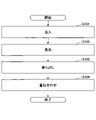
- FIG. 5 is a flow chart illustrating a method of manufacturing a fender liner according to one embodiment.
- 6(A) is a cross-sectional view showing the test piece of Example 1
- FIG. 6(B) is a cross-sectional view showing the test piece of Example 2
- FIG. 6(C) is a cross-sectional view showing the test piece of Example 3.
- It is a diagram.
- FIG. 7 is a diagram showing the sound absorption properties of the test pieces of Examples 1 to 3.
- FIG. 7 is a diagram
- Non-woven fabric is defined as follows in Japanese Industrial Standards JIS L 0222:2001. A fibrous sheet, web or batt in which the fibers are unidirectionally or randomly oriented and are bonded together by entanglement and/or fusion and/or adhesion. However, paper, woven fabrics, knitted fabrics, tufts and crepe felts are excluded.
- FIG. 1 the white arrow indicates the traveling direction of the vehicle, with the left side being the front side of the vehicle and the right side being the rear side of the vehicle.
- the fender liner 1 is arranged inside the tire house 31 .
- the tire house 31 is a space that accommodates the tire 2 of the vehicle body 3 .
- the fender liner 1 is curved along the outer periphery of the tire 2 .
- the fender liner 1 forms a certain or more gap with the tire 2 so as not to contact the tire 2. ⁇
- the fender liner 1 prevents foreign objects such as pebbles thrown up while the vehicle is running from colliding with the vehicle body 3 .
- the fender liner 1 absorbs running noise of the vehicle, collision noise of foreign objects, and the like.
- the fender liner 1 is attached to the vehicle body 3 with fasteners 4 .
- the fixture 4 includes, for example, pins.
- the fender liner 1 includes a nonwoven fabric 11 and a foam 12.
- the foam 12 is formed by laminating the nonwoven fabric 11 after foaming outside the nonwoven fabric 11 . Therefore, an integrated layer in which the nonwoven fabric 11 and the foam 12 are integrated does not exist between the nonwoven fabric 11 and the foam 12 . Instead of the integrated layer, there is a dividing surface that divides the nonwoven fabric 11 and the foam 12 . The nonwoven fabric 11 and the foam 12 are separable at the dividing plane.
- the integrated layer is formed by injecting a resin composition into the interior space of the mold with the nonwoven fabric placed in a part of the interior space of the mold, impregnating the nonwoven fabric with the resin composition, and forming the resin inside the nonwoven fabric. Obtained by foaming the composition. When there is an integrated layer, even if the nonwoven fabric 11 and the foam 12 are to be separated, part of the foam 12 bites into the nonwoven fabric 11 .
- the foam 12 of this embodiment is, as described above, superimposed on the nonwoven fabric 11 after foaming outside the nonwoven fabric 11 . Therefore, an integrated layer in which the nonwoven fabric 11 and the foam 12 are integrated does not exist between the nonwoven fabric 11 and the foam 12 . Instead of the integrated layer, there is a dividing surface that divides the nonwoven fabric 11 and the foam 12 . The nonwoven fabric 11 and the foam 12 are separable at the dividing plane. Therefore, the separability of the nonwoven fabric 11 and the foam 12 can be improved, and the recycling rate of the nonwoven fabric 11 can be improved.
- the nonwoven fabric 11 and the foam 12 are adjacent to each other, and there is no adhesive layer between the nonwoven fabric 11 and the foam 12. Without the adhesive layer that bonds the nonwoven fabric 11 and the foam 12, the nonwoven fabric 11 and the foam 12 can be easily separated, and the recycling rate of the nonwoven fabric 11 can be further improved. Moreover, if there is no adhesive layer, reflection of sound waves by the adhesive layer can be prevented.
- the nonwoven fabric 11 and the foam 12 are adjacent to each other, and no adhesive layer exists between the nonwoven fabric 11 and the foam 12, but an adhesive layer may exist.
- the adhesive layer may be provided only on part of the interface between the nonwoven fabric 11 and the foam 12 .
- the adhesive layer may be provided in a checkered pattern, in a stripe pattern, or in a frame shape only on the periphery.
- the nonwoven fabric 11 has a curved shape along the outer circumference of the tire 2 .
- the foam 12 is provided on the surface 111 of the nonwoven fabric 11 opposite to the tire 2 .
- the foam 12 is provided, for example, only on a portion of the surface 111 of the nonwoven fabric 11 opposite to the tire 2 .
- the nonwoven fabric 11 can be fixed to each mounting portion 32 with the fixing tool 4 in a state in which the foam 12 is fitted between the plurality of mounting portions 32 of the vehicle body 3 and the nonwoven fabric 11 is in contact with each mounting portion 32 . Therefore, even if the foam 12 is simply placed on the nonwoven fabric 11 without fixing the foam 12 to the nonwoven fabric 11 , displacement of the foam 12 with respect to the vehicle body 3 can be suppressed. Moreover, since the foam 12 is simply placed on the nonwoven fabric 11, the foam 12 and the nonwoven fabric 11 can be easily separated.
- the foam 12 may be provided on the entire surface 111 of the nonwoven fabric 11 opposite to the tire 2 . In this case, by covering the entire nonwoven fabric 11 with the foam 12 , the sound absorption coefficient can be improved over the entire fender liner 1 .
- the foam 12 includes a first foam layer 121 provided on at least a portion of the surface 111 of the nonwoven fabric 11 opposite to the tire 2 , and a first foam layer 121 opposite to the tire 2 . and a second foam layer 122 provided on at least a portion of the side surface.
- the first foam layer 121 is provided only on a part of the surface 111 of the nonwoven fabric 11 opposite to the tire 2, and one part of the surface of the first foam layer 121 opposite to the tire 2 is provided.
- the second foam layer 122 is provided only in the portion, by fitting the second foam layer 122 into the recessed portion 33 of the vehicle body 3 , displacement of the foam body 12 with respect to the vehicle body 3 can be further suppressed.
- the first foam layer 121 and the second foam layer 122 for example, have the same composition and are foamed simultaneously inside the same mold. That is, the first foam layer 121 and the second foam layer 122 are integrated. By integrating the first foam layer 121 and the second foam layer 122, the handleability of the foam 12 can be improved.
- first foam layer 121 and the second foam layer 122 may have different compositions and may have different sound absorption characteristics (for example, different sound absorption peak frequencies). As a result, the noise level can be reduced in a wide frequency band. Also, the first foam layer 121 and the second foam layer 122 may be separately molded inside different molds.
- the second foam layer 122 may be provided on the entire surface of the first foam layer 121 opposite to the tire 2. .
- the sound absorption coefficient of the foam 12 can be improved.
- the foam 12 includes a first foam layer 121 provided on the entire surface 111 of the nonwoven fabric 11 opposite to the tire 2 , and a first foam layer 121 provided on the opposite side of the tire 2 . and a second foam layer 122 formed on at least a portion of the surface of the .
- the second foam layer 122 is fitted between the plurality of mounting portions 32 of the vehicle body 3 , and the first foam layer 121 is in contact with each mounting portion 32 . 11 can be fixed. Therefore, even if the foam 12 is simply placed on the nonwoven fabric 11 without fixing the foam 12 to the nonwoven fabric 11 , displacement of the foam 12 with respect to the vehicle body 3 can be suppressed. Moreover, since the foam 12 is simply placed on the nonwoven fabric 11, the foam 12 and the nonwoven fabric 11 can be easily separated.
- the foam 12 may further include a third foam layer 123 provided on at least part of the surface of the second foam layer 122 opposite to the tire 2 .
- a third foam layer 123 provided on at least part of the surface of the second foam layer 122 opposite to the tire 2 .
- the foam 12 consists of a first foam layer 121 provided on the entire surface 111 of the nonwoven fabric 11 opposite to the tire 2 and a A second foam layer 122 provided only on a part of the surface and a third foam layer 123 provided only on a part of the surface of the second foam layer 122 opposite to the tire 2 may be included.
- the third foam layer 123 into the recessed portion 33 of the vehicle body 3 , displacement of the foam 12 with respect to the vehicle body 3 can be further suppressed.
- the first foam layer 121, the second foam layer 122, and the third foam layer 123 for example, have the same composition and are foamed simultaneously inside the same mold. That is, the first foam layer 121, the second foam layer 122, and the third foam layer 123 are integrated. By integrating the first foam layer 121, the second foam layer 122, and the third foam layer 123, the handleability of the foam 12 can be improved.
- first foam layer 121 and the second foam layer 122 and the third foam layer 123 may have different compositions and may have different sound absorption characteristics (for example, different sound absorption peak frequencies). As a result, the noise level can be reduced in a wide frequency band. Also, the first foam layer 121, the second foam layer 122, and the third foam layer 123 may be separately molded inside different molds.
- the third foam layer 123 is provided on the entire surface of the second foam layer 122 opposite to the tire 2 .
- the second foam layer 122 and the third foam layer 123 have different densities, so that the sound absorption coefficient of the foam 12 can be improved.
- the nonwoven fabric 11 is an aggregate of polyester (PEs) fibers, polyethylene (PE) fibers, polypropylene (PP) fibers, or the like.
- the nonwoven fabric 11 may contain multiple types of fibers, and may contain, for example, polyester fibers and rayon fibers. Specific examples of polyester fibers include polyethylene terephthalate (PET) fibers.
- the thickness of the nonwoven fabric 11 is, for example, 0.10 mm to 10 mm.
- the density of the nonwoven fabric 11 is, for example, 5.0 kg/m 3 to 250 kg/m 3 .
- the density of the nonwoven fabric 11 is a so-called bulk density, which is measured according to JIS K7222:2005 "Foamed plastics and rubbers-Determination of apparent density”.
- the density of the nonwoven fabric 11 is preferably 25 kg/m 3 to 220 kg/m 3 , more preferably 50 kg/m 3 to 200 kg/m 3 , still more preferably 100 kg/m 3 to 180 kg/m 3 .
- the nonwoven fabric 11 has a sound absorption coefficient of, for example, 0.1 to 0.5.
- the sound absorption coefficient of the non-woven fabric 11 is measured by cutting out a 10 mm-thick test piece, vertically injecting a 1000 Hz sound wave, and measuring it in accordance with JIS A1405-2:2007 "Measurement of sound absorption coefficient and impedance by acoustic tube".
- the nonwoven fabric 11 preferably has a sound absorption coefficient of 0.2 to 0.4.
- a sound absorption coefficient of 1.0 means that no sound is reflected.
- the foam 12 has a three-dimensional network skeleton.
- the foam 12 has many cells inside. A large number of bubbles are connected to each other, and sound waves propagate inside them. At that time, the air vibrates inside the foam 12 . Friction is generated between the three-dimensional network skeleton of the foam 12 and the air, and sound wave energy is converted into heat energy. As a result, sound is absorbed. The noise level outside the vehicle and the noise level inside the vehicle can be reduced.
- the foam 12 While the nonwoven fabric 11 contains two-dimensionally oriented fibers, the foam 12 has a three-dimensionally stretched network skeleton. Therefore, the foam 12 can improve the sound absorption coefficient compared to the nonwoven fabric 11 . Moreover, since the foam 12 has a three-dimensionally stretched network skeleton and is continuously connected, shape retention can be improved.
- the foam 12 is, for example, a polyurethane foam.
- a polyurethane foam is a so-called polyurethane foam, and is obtained by foaming and solidifying a resin composition containing a polyisocyanate, a polyol, a catalyst, and a foaming agent.
- the foaming agent contains water.
- the foaming agent may contain chlorine. Details of the resin composition will be described later.
- the foam 12 is a polyurethane foam in this embodiment, but may be a polyacrylic, melamine, rubber, polyolefin, or polyimide foam. These materials, including polyurethane, are lightweight and excellent in shape retention.
- the thickness of the foam 12 is, for example, 3 mm to 30 mm, preferably 4 mm to 25 mm, more preferably 5 mm to 20 mm, from the viewpoint of achieving both lightness and sound absorption.
- the density of the foam 12 is, for example, 20 kg/m 3 to 140 kg/m 3 from the viewpoint of compatibility between lightness and sound absorption.
- the density of the foam 12 is a so-called bulk density, which is measured in accordance with JIS K7222:2005 "Foamed plastics and rubbers-Determination of apparent density-”.
- the density of foam 12 is preferably between 30 kg/m 3 and 130 kg/m 3 , more preferably between 55 kg/m 3 and 120 kg/m 3 .
- the sound absorption coefficient of the foam 12 is, for example, 0.4 to 1.0.
- the sound absorption coefficient of the foam 12 is measured by cutting out a test piece with a thickness of 10 mm, vertically irradiating a sound wave of 1000 Hz, and measuring it according to JIS A1405-2:2007 "Measurement of sound absorption coefficient and impedance by acoustic tube".
- the foam 12 preferably has a sound absorption coefficient of 0.4 to 1.0.
- a sound absorption coefficient of 1.0 means that no sound is reflected.
- the manufacturing method of the fender liner 1 includes steps S101 to S104 of FIG. 5, for example.
- a resin composition is injected into the internal space of the mold.
- the mold is a mold from the viewpoint of temperature controllability.
- the mold may be a sand mold, a wooden mold, or a resin mold.
- the mold temperature is adjusted between 50°C and 70°C.
- the temperature of the mold is 50°C or higher, the polymerization reaction and foaming reaction can proceed. In addition, if the temperature of the mold is 70 ° C. or less, it is possible to moderately suppress these reaction rates, it is possible to suppress the completion of solidification before the resin spreads throughout the interior space of the mold, and incomplete filling can be prevented. phenomenon, that is, the occurrence of a short circuit can be suppressed.
- the temperature distribution of the molding die may be uniform or non-uniform. In the latter case, the temperature difference can control the polymerization reaction and foaming reaction of the resin composition.
- the mold is divided into, for example, a lower mold and an upper mold, and is configured so that the internal space can be opened and closed.
- the injection of the resin composition is performed with the inner space closed between the lower mold and the upper mold.
- step S102 the resin composition is foamed in the inner space of the mold to mold the foam 12.
- the foam 12 is molded to the same shape and dimensions as the interior space of the mold. Therefore, foams 12 having the same shape and the same dimensions can be mass-produced.
- the shape and dimensions of the foam 12 are determined by the shape and dimensions of the inner space of the mold, a fine structure can be imparted, and post-processing such as cutting or pressing is unnecessary.
- step S103 the foam 12 is removed from the mold.
- the foam 12 is taken out, for example, in a state where the inner space is opened between the lower mold and the upper mold.
- step S104 the foam 12 removed from the mold is superimposed on the nonwoven fabric 11.
- the fender liner 1 is obtained.
- the fender liner 1 is attached to the vehicle body 3 with fasteners 4 .
- a step of forming a water-repellent layer (not shown) on the surface of the fender liner 1 facing the tire 2 may be included.
- the water-repellent layer is formed, for example, on the surface of the nonwoven fabric 11 facing the tire 2 .
- the timing of forming the water-repellent layer on the nonwoven fabric 11 may be before or after the nonwoven fabric 11 and the foam 12 are stacked.
- the foam 12 is arranged closer to the tire 2 than the nonwoven fabric 11 , the water-repellent layer is formed on the surface of the foam 12 facing the tire 2 .
- the water-repellent layer makes water droplets scattered by the tire 2 slippery. Therefore, it is possible to suppress the remaining water droplets and the formation of an ice film. If the ice film does not form, damage due to detachment of the ice film does not occur.
- the water-repellent layer is formed of, for example, a fluorine-based, silicone-based, or low-polar hydrocarbon-based coating agent such as polyethylene or polypropylene.
- the water-repellent layer may have air permeability. Sound waves such as running noise of the tire 2 easily enter the inside of the fender liner 1 compared to the case where the water-repellent layer does not have air permeability. Therefore, reflection of sound waves can be suppressed.
- a water-repellent layer having air permeability is formed by, for example, a needle punch method or a spray coating method.
- the resin composition that is the raw material of the foam 12 will be described.
- the resin composition contains polyisocyanate, polyol, catalyst, and blowing agent.
- the resin composition may further contain additives.
- the resin composition is usually prepared by mixing a system liquid containing raw materials other than polyisocyanate and polyisocyanate.
- polyisocyanates examples include toluene diisocyanate (TDI), diphenylmethane diisocyanate (MDI), polymethylene polyphenyl isocyanate (common name: crude MDI), xylylene diisocyanate (XDI), isophorone diisocyanate (IPDI) and hexamethylene diisocyanate (HMDI). prepolymer-modified, isocyanurate-modified, urea-modified and carbodiimide-modified polyisocyanates of, but not limited to.
- TDI may be either 2,4-TDI or 2,6-TDI, or may be a mixture.
- MDI may be any of 2,2'-MDI, 2,4'-MDI and 4,4'-MDI, or a mixture of two or three of these.
- polyols examples include polyoxyalkylene polyols and polyester polyols.
- Water can be used as the foaming agent, but is not limited to this.
- an inert compound with a low boiling point is preferred.
- inert compounds include inert gases, and saturated hydrocarbons having a boiling point of 70° C. or less and carbon atoms of 8 or less, in which hydrogen atoms bonded to carbon atoms may be substituted with halogen atoms.
- the halogen atom is, for example, a chlorine atom or a fluorine atom.
- saturated hydrocarbons include, but are not limited to, butane, pentane, hexane, dichloromethane (methylene chloride), trichloroethane and various Freon compounds.
- a foaming agent may be used individually by 1 type, and may use 2 or more types together.
- the catalyst is at least one selected from the group consisting of amine-based catalysts and tin-based catalysts.
- One type of catalyst may be used alone, or two or more types may be used in combination.
- the amine-based catalysts include triethylenediamine, bis(2-dimethylaminoethyl)ether, N,N,N',N'-tetramethylhexamethylenediamine, N,N-dimethylaminoethoxyethoxyethanol, N,N -dimethylamino-6-hexanol, N,N-dimethylaminoethoxyethanol, a compound obtained by adding 2 moles of ethylene oxide to N,N-dimethylaminoethoxyethanol, and 5-(N,N-dimethyl)amino-3-methyl -1-pentanol, but not limited to these.
- tin-based catalysts examples include tin 2-ethylhexanoate, di-n-butyltin oxide, di-n-butyltin dilaurate, di-n-butyltin diacetate, di-n-octyltin oxide, and di-n-octyl. but are not limited to tin dilaurate, monobutyltin trichloride, di-n-butyltin dialkylmercaptan and di-n-octyltin dialkylmercaptan.
- a foam stabilizer may be included as an additive.
- foam stabilizers include, but are not limited to, silicone foam stabilizers or fluorine-containing compound foam stabilizers.
- a foam stabilizer may be used individually by 1 type, and may use 2 or more types together.
- a cross-linking agent may be included as an additive.
- a compound having two or more active hydrogen-containing groups selected from hydroxyl groups, primary amino groups and secondary amino groups can be selected.
- cross-linking agents include ethylene glycol, propylene glycol, 1,4-butanediol, neopentyl glycol, 1,6-hexanediol, diethylene glycol, triethylene glycol, dipropylene glycol, glycerin, trimethylolpropane, pentaerythritol, and diglycerin.
- cross-linking agent polyoxyalkylene polyols having a molecular weight/number of hydroxyl groups of less than 500 can also be used.
- One type of crosslinking agent may be used alone, or two or more types may be used in combination.
- Additives other than those mentioned above include anti-aging agents such as emulsifiers, antioxidants and ultraviolet absorbers, fillers such as calcium carbonate and barium sulfate, plasticizers, colorants, flame retardants, anti-mold agents and foam breakers. but not limited thereto, and additives conventionally used in polyurethane foams can be used.
- Example 1 is an example, and Examples 2 and 3 are comparative examples.
- the same resin composition was used as the material of the foam.
- 109.3 parts by mass of the system liquid and 39.3 parts by mass of polyisocyanate (a mixture of TDI and MDI, manufactured by Tosoh Corporation, trade name: Coronate 1021) are placed in a container and mixed with a high-speed mixer, Prepared at room temperature.
- the system liquid contains 60 parts by mass of polyoxyalkylene polyol 1 (manufactured by AGC, trade name: EXCENOL820), 40 parts by mass of polyoxyalkylene polyol 2 (manufactured by AGC, trade name: EXCENOL923), and water as a blowing agent.
- Example 1 the resin composition was injected into the inner space of the mold and foamed in the inner space of the mold to obtain a foam 52 shown in FIG. 6(A).
- This foam 52 and Ambic's product name SN50B (PET fiber) are press-compressed at 170 ° C. and 1.6 MPa for 3 minutes using a miniTEST PRESS 10 type heating press (manufactured by Toyo Seiki Co., Ltd.) to obtain a thickness of 1.
- a nonwoven fabric 51 having a thickness of 0.3 mm was superimposed to prepare a test piece 5 .
- the thickness of the nonwoven fabric 51 was 1.3 mm
- the thickness of the foam 52 was 8.7 mm
- the thickness of the test piece 5 was 10 mm.
- Example 2 SN50B (PET fiber) manufactured by Ambic Co., Ltd. was used in part of the inner space of the mold at 100 ° C. and a pressure of 0.3 MPa using a miniTESTPRESS 10 type heating press (manufactured by Toyo Seiki Co., Ltd.). After setting a nonwoven fabric having a thickness of 2.7 mm by pressing for 1 minute, the resin composition was injected into the inner space of the mold, and the nonwoven fabric was impregnated with the resin composition and foamed. As a result, as shown in FIG. 6B, a test piece 6 having an integrated layer 63 in which the nonwoven fabric and the foam are integrated between the nonwoven fabric 61 and the foam 62 was obtained.
- the nonwoven fabric 61 had a thickness of 0.2 mm
- the foam 62 had a thickness of 7.3 mm
- the integrated layer 63 had a thickness of 2.5 mm
- the test piece 6 had a thickness of 10 mm.
- Example 3 As shown in FIG. 6(C), a test piece 7 composed only of nonwoven fabric 71 was produced. The thickness of the test piece 7 was 10 mm.
- As the non-woven fabric two layers of SN50B (PET fiber) manufactured by Ambic Co., Ltd., which is a trade name, are used without being press-compressed.
- Fig. 7 shows the sound absorption properties of test pieces 5-7 of Examples 1-3.
- the frequency dependence of the normal incidence sound absorption coefficient was measured. WinZacMTX manufactured by Nippon Acoustic Engineering Co., Ltd. was used for the measurement.
- sound waves were vertically incident on the nonwoven fabrics 51, 61, and 71, as indicated by white arrows in FIG.
- Example 3 Compared to Example 3, the sound absorption coefficient was higher around 1000 Hz, which is typical as the frequency of vehicle running noise. It is presumed that this is because in Examples 1 and 2, unlike Example 3, the test piece contains foam. In addition, in Example 1, compared to Example 2, the sound absorption coefficient was higher in a frequency band higher than 1000 Hz. This is presumably because in Example 1, unlike Example 2, the test piece did not include an integrated layer.
Landscapes
- Engineering & Computer Science (AREA)
- Chemical & Material Sciences (AREA)
- Combustion & Propulsion (AREA)
- Transportation (AREA)
- Mechanical Engineering (AREA)
- Laminated Bodies (AREA)
Priority Applications (1)
| Application Number | Priority Date | Filing Date | Title |
|---|---|---|---|
| JP2022576578A JP7779270B2 (ja) | 2021-01-25 | 2021-12-27 | フェンダーライナー及びその製造方法 |
Applications Claiming Priority (2)
| Application Number | Priority Date | Filing Date | Title |
|---|---|---|---|
| JP2021009713 | 2021-01-25 | ||
| JP2021-009713 | 2021-01-25 |
Publications (1)
| Publication Number | Publication Date |
|---|---|
| WO2022158266A1 true WO2022158266A1 (ja) | 2022-07-28 |
Family
ID=82549727
Family Applications (1)
| Application Number | Title | Priority Date | Filing Date |
|---|---|---|---|
| PCT/JP2021/048512 Ceased WO2022158266A1 (ja) | 2021-01-25 | 2021-12-27 | フェンダーライナー及びその製造方法 |
Country Status (2)
| Country | Link |
|---|---|
| JP (1) | JP7779270B2 (https=) |
| WO (1) | WO2022158266A1 (https=) |
Citations (4)
| Publication number | Priority date | Publication date | Assignee | Title |
|---|---|---|---|---|
| JPS54109237U (https=) * | 1978-01-13 | 1979-08-01 | ||
| JP2001039343A (ja) * | 1999-05-26 | 2001-02-13 | Puramakku Kk | フェンダライナ |
| JP2002348767A (ja) * | 2001-05-23 | 2002-12-04 | Toyoda Gosei Co Ltd | 吸音材及び自動車外装用吸音材 |
| WO2017141801A1 (ja) * | 2016-02-19 | 2017-08-24 | 住江織物株式会社 | 自動車用内外装材用シート及びその製造方法 |
Family Cites Families (1)
| Publication number | Priority date | Publication date | Assignee | Title |
|---|---|---|---|---|
| JP5283886B2 (ja) * | 2006-10-25 | 2013-09-04 | トーア紡マテリアル株式会社 | 防音緩衝材 |
-
2021
- 2021-12-27 WO PCT/JP2021/048512 patent/WO2022158266A1/ja not_active Ceased
- 2021-12-27 JP JP2022576578A patent/JP7779270B2/ja active Active
Patent Citations (4)
| Publication number | Priority date | Publication date | Assignee | Title |
|---|---|---|---|---|
| JPS54109237U (https=) * | 1978-01-13 | 1979-08-01 | ||
| JP2001039343A (ja) * | 1999-05-26 | 2001-02-13 | Puramakku Kk | フェンダライナ |
| JP2002348767A (ja) * | 2001-05-23 | 2002-12-04 | Toyoda Gosei Co Ltd | 吸音材及び自動車外装用吸音材 |
| WO2017141801A1 (ja) * | 2016-02-19 | 2017-08-24 | 住江織物株式会社 | 自動車用内外装材用シート及びその製造方法 |
Also Published As
| Publication number | Publication date |
|---|---|
| JP7779270B2 (ja) | 2025-12-03 |
| JPWO2022158266A1 (https=) | 2022-07-28 |
Similar Documents
| Publication | Publication Date | Title |
|---|---|---|
| KR101005985B1 (ko) | 소음 경감을 위한 삼차원 형상 기재의 제조 방법 | |
| KR101137527B1 (ko) | 압축 성형을 이용한 자동차용 내장재의 제조방법 | |
| EP2977259B1 (en) | Cushion pad | |
| US9573504B2 (en) | Cushion pad | |
| CN101331166B (zh) | 制造汽车车顶内衬的方法 | |
| US8889574B2 (en) | Foam laminate product and process for production thereof | |
| CA2533692C (en) | Foam laminate product and process for production thereof | |
| CN102026803B (zh) | 泡沫层压产品及其生产方法 | |
| CN102317068A (zh) | 泡沫层压产品以及其生产方法 | |
| JP7779270B2 (ja) | フェンダーライナー及びその製造方法 | |
| JP7521542B2 (ja) | フェンダーライナーの製造方法 | |
| US20230303014A1 (en) | Fender liner, manufacturing method of fender liner, and vehicle | |
| WO2023063114A1 (ja) | フェンダーライナー及びその製造方法 | |
| CN109196029A (zh) | 由热塑性弹性体制备的中空颗粒和多孔模塑体 | |
| JP7521541B2 (ja) | フェンダーライナー及び車両 | |
| JP7414061B2 (ja) | ポリウレタンフォーム、及び車両用防音材 | |
| JP7722388B2 (ja) | 車両及びフェンダーライナーの製造方法 | |
| ES2389858T3 (es) | Procedimiento para la fabricación de una pieza compuesta | |
| WO2023171183A1 (ja) | 防音材、防音構造および防音材の製造方法 | |
| WO2021132387A1 (ja) | ポリウレタンフォーム、及び車両用防音材 | |
| CN120266200A (zh) | 隔音材料及其制造方法 |
Legal Events
| Date | Code | Title | Description |
|---|---|---|---|
| 121 | Ep: the epo has been informed by wipo that ep was designated in this application |
Ref document number: 21921367 Country of ref document: EP Kind code of ref document: A1 |
|
| ENP | Entry into the national phase |
Ref document number: 2022576578 Country of ref document: JP Kind code of ref document: A |
|
| NENP | Non-entry into the national phase |
Ref country code: DE |
|
| 122 | Ep: pct application non-entry in european phase |
Ref document number: 21921367 Country of ref document: EP Kind code of ref document: A1 |