WO2022158182A1 - リリーフバルブ - Google Patents
リリーフバルブ Download PDFInfo
- Publication number
- WO2022158182A1 WO2022158182A1 PCT/JP2021/046413 JP2021046413W WO2022158182A1 WO 2022158182 A1 WO2022158182 A1 WO 2022158182A1 JP 2021046413 W JP2021046413 W JP 2021046413W WO 2022158182 A1 WO2022158182 A1 WO 2022158182A1
- Authority
- WO
- WIPO (PCT)
- Prior art keywords
- space
- oil
- pressure
- valve
- valve body
- Prior art date
- Legal status (The legal status is an assumption and is not a legal conclusion. Google has not performed a legal analysis and makes no representation as to the accuracy of the status listed.)
- Ceased
Links
Images




Classifications
-
- F—MECHANICAL ENGINEERING; LIGHTING; HEATING; WEAPONS; BLASTING
- F16—ENGINEERING ELEMENTS AND UNITS; GENERAL MEASURES FOR PRODUCING AND MAINTAINING EFFECTIVE FUNCTIONING OF MACHINES OR INSTALLATIONS; THERMAL INSULATION IN GENERAL
- F16K—VALVES; TAPS; COCKS; ACTUATING-FLOATS; DEVICES FOR VENTING OR AERATING
- F16K17/00—Safety valves; Equalising valves, e.g. pressure relief valves
- F16K17/02—Safety valves; Equalising valves, e.g. pressure relief valves opening on surplus pressure on one side; closing on insufficient pressure on one side
- F16K17/04—Safety valves; Equalising valves, e.g. pressure relief valves opening on surplus pressure on one side; closing on insufficient pressure on one side spring-loaded
- F16K17/0466—Safety valves; Equalising valves, e.g. pressure relief valves opening on surplus pressure on one side; closing on insufficient pressure on one side spring-loaded with a special seating surface
-
- F—MECHANICAL ENGINEERING; LIGHTING; HEATING; WEAPONS; BLASTING
- F16—ENGINEERING ELEMENTS AND UNITS; GENERAL MEASURES FOR PRODUCING AND MAINTAINING EFFECTIVE FUNCTIONING OF MACHINES OR INSTALLATIONS; THERMAL INSULATION IN GENERAL
- F16K—VALVES; TAPS; COCKS; ACTUATING-FLOATS; DEVICES FOR VENTING OR AERATING
- F16K17/00—Safety valves; Equalising valves, e.g. pressure relief valves
- F16K17/02—Safety valves; Equalising valves, e.g. pressure relief valves opening on surplus pressure on one side; closing on insufficient pressure on one side
- F16K17/04—Safety valves; Equalising valves, e.g. pressure relief valves opening on surplus pressure on one side; closing on insufficient pressure on one side spring-loaded
-
- F—MECHANICAL ENGINEERING; LIGHTING; HEATING; WEAPONS; BLASTING
- F04—POSITIVE - DISPLACEMENT MACHINES FOR LIQUIDS; PUMPS FOR LIQUIDS OR ELASTIC FLUIDS
- F04C—ROTARY-PISTON, OR OSCILLATING-PISTON, POSITIVE-DISPLACEMENT MACHINES FOR LIQUIDS; ROTARY-PISTON, OR OSCILLATING-PISTON, POSITIVE-DISPLACEMENT PUMPS
- F04C14/00—Control of, monitoring of, or safety arrangements for, machines, pumps or pumping installations
- F04C14/24—Control of, monitoring of, or safety arrangements for, machines, pumps or pumping installations characterised by using valves controlling pressure or flow rate, e.g. discharge valves or unloading valves
- F04C14/26—Control of, monitoring of, or safety arrangements for, machines, pumps or pumping installations characterised by using valves controlling pressure or flow rate, e.g. discharge valves or unloading valves using bypass channels
-
- F—MECHANICAL ENGINEERING; LIGHTING; HEATING; WEAPONS; BLASTING
- F04—POSITIVE - DISPLACEMENT MACHINES FOR LIQUIDS; PUMPS FOR LIQUIDS OR ELASTIC FLUIDS
- F04C—ROTARY-PISTON, OR OSCILLATING-PISTON, POSITIVE-DISPLACEMENT MACHINES FOR LIQUIDS; ROTARY-PISTON, OR OSCILLATING-PISTON, POSITIVE-DISPLACEMENT PUMPS
- F04C2/00—Rotary-piston machines or pumps
- F04C2/08—Rotary-piston machines or pumps of intermeshing-engagement type, i.e. with engagement of co-operating members similar to that of toothed gearing
- F04C2/10—Rotary-piston machines or pumps of intermeshing-engagement type, i.e. with engagement of co-operating members similar to that of toothed gearing of internal-axis type with the outer member having more teeth or tooth-equivalents, e.g. rollers, than the inner member
- F04C2/102—Rotary-piston machines or pumps of intermeshing-engagement type, i.e. with engagement of co-operating members similar to that of toothed gearing of internal-axis type with the outer member having more teeth or tooth-equivalents, e.g. rollers, than the inner member the two members rotating simultaneously around their respective axes
-
- F—MECHANICAL ENGINEERING; LIGHTING; HEATING; WEAPONS; BLASTING
- F16—ENGINEERING ELEMENTS AND UNITS; GENERAL MEASURES FOR PRODUCING AND MAINTAINING EFFECTIVE FUNCTIONING OF MACHINES OR INSTALLATIONS; THERMAL INSULATION IN GENERAL
- F16K—VALVES; TAPS; COCKS; ACTUATING-FLOATS; DEVICES FOR VENTING OR AERATING
- F16K27/00—Construction of housing; Use of materials therefor
- F16K27/02—Construction of housing; Use of materials therefor of lift valves
- F16K27/0209—Check valves or pivoted valves
-
- F—MECHANICAL ENGINEERING; LIGHTING; HEATING; WEAPONS; BLASTING
- F04—POSITIVE - DISPLACEMENT MACHINES FOR LIQUIDS; PUMPS FOR LIQUIDS OR ELASTIC FLUIDS
- F04C—ROTARY-PISTON, OR OSCILLATING-PISTON, POSITIVE-DISPLACEMENT MACHINES FOR LIQUIDS; ROTARY-PISTON, OR OSCILLATING-PISTON, POSITIVE-DISPLACEMENT PUMPS
- F04C14/00—Control of, monitoring of, or safety arrangements for, machines, pumps or pumping installations
- F04C14/24—Control of, monitoring of, or safety arrangements for, machines, pumps or pumping installations characterised by using valves controlling pressure or flow rate, e.g. discharge valves or unloading valves
-
- F—MECHANICAL ENGINEERING; LIGHTING; HEATING; WEAPONS; BLASTING
- F04—POSITIVE - DISPLACEMENT MACHINES FOR LIQUIDS; PUMPS FOR LIQUIDS OR ELASTIC FLUIDS
- F04C—ROTARY-PISTON, OR OSCILLATING-PISTON, POSITIVE-DISPLACEMENT MACHINES FOR LIQUIDS; ROTARY-PISTON, OR OSCILLATING-PISTON, POSITIVE-DISPLACEMENT PUMPS
- F04C14/00—Control of, monitoring of, or safety arrangements for, machines, pumps or pumping installations
- F04C14/28—Safety arrangements; Monitoring
-
- F—MECHANICAL ENGINEERING; LIGHTING; HEATING; WEAPONS; BLASTING
- F04—POSITIVE - DISPLACEMENT MACHINES FOR LIQUIDS; PUMPS FOR LIQUIDS OR ELASTIC FLUIDS
- F04C—ROTARY-PISTON, OR OSCILLATING-PISTON, POSITIVE-DISPLACEMENT MACHINES FOR LIQUIDS; ROTARY-PISTON, OR OSCILLATING-PISTON, POSITIVE-DISPLACEMENT PUMPS
- F04C2240/00—Components
- F04C2240/30—Casings or housings
-
- F—MECHANICAL ENGINEERING; LIGHTING; HEATING; WEAPONS; BLASTING
- F04—POSITIVE - DISPLACEMENT MACHINES FOR LIQUIDS; PUMPS FOR LIQUIDS OR ELASTIC FLUIDS
- F04C—ROTARY-PISTON, OR OSCILLATING-PISTON, POSITIVE-DISPLACEMENT MACHINES FOR LIQUIDS; ROTARY-PISTON, OR OSCILLATING-PISTON, POSITIVE-DISPLACEMENT PUMPS
- F04C2270/00—Control; Monitoring or safety arrangements
- F04C2270/58—Valve parameters
Definitions
- the present invention relates to relief valves.
- a relief valve (also called a "relief valve” or “safety valve”) that releases liquid in order to prevent a certain level of pressure from being applied to liquids such as oil. .)It has been known.
- an electromagnetic clutch adjusts the position of the opening/closing portion to control the opening/closing of the suction port.
- the suction port is opened based on the control of opening and closing the suction port, the suction port and the discharge port are brought into communication with each other, and the oil flowing through the flow path is discharged through the suction port and the discharge port.
- the solenoid valve by opening and closing, adjusts part of the oil flowing in the flow path to flow to another flow path.
- such a technique is known (for example, patent document 1 etc.).
- the present invention has been made in view of the circumstances described above, and an object of the present invention is to provide a relief valve capable of suppressing hysteresis.
- the present invention is a relief valve that switches whether or not to discharge oil by movement of a valve body, a first space in which the valve body moves; a second space connected to the first space and having a smaller diameter than the first space; an elastic body in contact with the valve body; a seal portion installed in the circumferential direction of the valve body; and a third space formed in the first space.
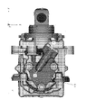
- FIG. 1 is a first diagram showing an example of a pump cover with a relief valve
- Fig. 2 shows an example of a pump cover with a relief valve
- FIG. 4 is a diagram showing an example of a relief valve
- FIG. 10 is a diagram showing an example of a seat-separated state; It is a figure which shows the example of a valve-open state. It is a figure which shows an experimental result.
- FIG. 4 is a diagram showing an example of a contact portion; It is a figure which shows the formation example of a groove
- FIG. 1 is a diagram showing an example of an oil pump.
- An oil pump 1 as shown will be described below as an example. The details of the relief valve will be explained in another drawing. Also, the relief valve may be used in a place other than the oil pump 1 as shown.
- the relief valve can be applied to any oil pump that handles oil with a certain degree of viscosity. Also, the size of the oil pump is not limited.
- the oil pump 1 is an oil pump that can be used in an environment of -40°C to 120°C.
- the relief valve may further include a sealing member such as an O-ring.
- a sealing member such as an O-ring.
- the relief valve is installed integrally with the pump cover 10 installed on the oil pump 1 .
- the pump cover 10 has a relief valve. If the pump cover 10 has a relief valve, the relief valve can be easily replaced even in an oil pump that does not have a relief valve. Moreover, when it is integrated with the pump cover 10, space can be saved by saving parts.
- the pump cover 10 and the relief valve are integrated will be described below.
- the pump cover 10 is installed on the oil pump 1 as follows.
- FIG. 2 is a diagram showing an installation example of the pump cover.
- the pump cover 10 is installed at the lowest part of the oil pump 1 (refers to the lowest side in the Z-axis direction in the drawing. Note that the Z-axis direction is, for example, the direction of gravity). be.
- the installation position, orientation, range, etc. of the pump cover 10 are not limited to the illustrated format. That is, the pump cover 10 may be installed, for example, at a position other than the lowest part of the oil pump 1 .
- the pump cover 10 is attached to the main body of the oil pump 1 by screwing or the like.
- the oil pump 1 performs operations such as sucking up oil and sending the oil to a predetermined position.
- the relief valve discharges oil to the outside when the discharge pressure of the pump exceeds the set pressure of the relief valve.
- the oil pump 1 operates the relief valve to discharge oil to the outside when the discharge pressure of the pump exceeds the set pressure of the relief valve. Therefore, in the oil pump 1, the pressure on the discharge side of the pump (for example, the pressure in the discharge pipe or the casing of the pump, etc.) can be suppressed to a predetermined pressure or less.
- the pressure at which the relief valve discharges oil to the outside that is, the pressure that serves as a reference for the relief valve to discharge oil to the outside, is set in advance in consideration of pressure resistance and the like.
- the pressure at which the relief valve discharges the oil to the outside will be referred to as “valve opening pressure” (also referred to as “set pressure” or “cracking pressure”).
- the destination of oil discharged by the relief valve is, for example, the outside of the oil pump 1 (including a drain, etc.). However, the oil discharge destination of the relief valve may be returned to the suction side.
- valve opening pressure is a value that is set according to the pressure resistance of the piping on the pump discharge side or the equipment.
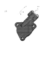
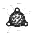
- FIG. 3 is a first view showing an example of a pump cover having a relief valve
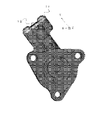
- FIG. 4 is a second diagram showing an example of a pump cover having a relief valve.
- FIG. 3 and 4 show the opposite side (hereinafter referred to as the "rear surface") of the pump cover 10 shown in FIG. 3 (hereinafter referred to as the "front surface”). This relationship is mainly shown.
- the relief plate 11 is installed at a position as shown. Also in the illustrated example, the pump cover 10 has a hole 12 . Through such holes 12, oil is discharged to the outside.
- the position, size, shape, etc. of the relief plate 11 and the hole 12 are not limited to the illustrated example.
- the relief valve has, for example, the following configuration.
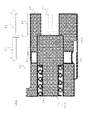
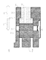
- FIG. 5 is a diagram showing an example of a relief valve.
- the figure is a cross-sectional view showing a part of the pump cover 10 that becomes the relief valve 100 . It should be noted that the cross-sectional view shown below is a view showing the cross section indicated by "AA" in FIG.
- the relief valve 100 is composed of, for example, a spring 101, a valve body 102, a housing 103, a seal portion 104, and the like.
- the relief valve 100 is desirably oriented in the direction of gravity. With such an orientation, the inclination of the relief valve 100 is easily suppressed, and the relief valve 100 can slide smoothly.
- the spring 101 is an example of an elastic body. Specifically, the spring 101 is installed so as to come into contact with the valve body 102 (the figure shows an example where the spring 101 is installed on the left side of the valve body 102).
- valve body 102 moves in the horizontal direction in the drawing.
- first direction 21 the left direction in the drawing
- second direction 22 the right direction in the drawing
- the spring 101 expands and contracts in the first direction 21 and the second direction 22 . Specifically, when force is applied to the valve body 102 from the right direction, the spring 101 contracts in the first direction 21 . Then, when the force applied to the valve body 102 becomes weaker, the spring 101 extends in the second direction 22 . That is, the spring 101 pushes and moves the valve body 102 in the second direction 22 with a restoring force. Therefore, the valve body 102 reciprocates in the first direction 21 and the second direction 22 due to expansion and contraction of the spring 101 .
- the elastic body may be any object that generates a force to move the valve body 102 by a restoring force. Therefore, the elastic body may be an object other than the spring 101, or a combination of the spring 101 and another object. However, the elastic body is preferably a spring in terms of oil resistance, heat resistance, durability, compression amount, and the like.
- the housing 103 has a shape having a first space 31, a second space 32, a third space 33, and the like. Specifically, in the illustrated example, the space on the left becomes the first space 31 and the space on the right becomes the second space 32 .
- the first space portion 31 is a space portion in which the valve body 102 is provided and in which the valve body 102 reciprocates in the longitudinal direction. Therefore, the diameter of the first space portion 31 (hereinafter referred to as the “first diameter 41”; in the figure, the vertical direction is the radial direction) varies depending on the diameter of the valve body 102 or the spring 101. It's size. Also, the first direction 21 and the second direction 22 match the longitudinal direction of the first space portion 31 .
- the second space 32 is a space with a diameter smaller than the first diameter 41 (hereinafter referred to as "second diameter 42").
- second diameter 42 is smaller than the first diameter 41
- boundary 34 is, for example, the Since the diameter is narrower than that of the one-space portion 31, it becomes a step.
- first space portion 31 and the second space portion 32 are space portions that are adjacent and connected to each other.
- the right end of the first space 31 coincides with the left end of the second space 32, and both the first space 31 and the second space 32 are connected spaces. Therefore, the second space portion 32 serves as a flow path through which oil flows from the main body of the oil pump 1 to the first space portion 31 .
- the second space 32 has an inlet 51 at a position as shown, for example.
- the inflow port 51 serves as a path through which oil flowing from the main body of the oil pump 1 flows into the second space 32 . Specifically, the oil flows into the second space 32 from the inlet 51 from the lower side to the upper side in the figure. Therefore, when a large amount of oil or a high pressure of oil flows into the second space 32 from the inlet 51 , a high pressure is applied to the valve body 102 in the first direction 21 .
- the oil that has flowed into the second space 32 and the spring 101 have a positional relationship in which force is applied to the opposing surfaces of the valve element 102 .
- the second space 32 and the spring 101 have a positional relationship in which they are installed symmetrically in the figure with the valve element 102 interposed therebetween. That is, the oil that has flowed into the second space 32 and the spring 101 apply force to the opposite ends of the valve body 102 .
- the end portion where the first space portion 31 and the second space portion 32 are connected (the right side in the drawing) is referred to as the "first end portion”.
- the end portion (on the left side in the figure) different from the first end portion is referred to as the "second end portion”.
- first surface 201 the surface formed on the first end side
- second surface 202 the surface formed on the second end side
- the spring 101 is installed, for example, in contact with the second surface 202 . Therefore, the restoring force by the spring 101 is applied to the second surface 202 . Therefore, a restoring force is applied to the second surface 202 (in the drawing, the force is directed from left to right), so the valve body 102 moves in the second direction 22 due to the restoring force.
- the oil that has flowed into the second space 32 applies pressure to the first surface 201 . Therefore, pressure is applied to the first surface 201 by the oil (a force directed from right to left in the drawing), so the valve body 102 moves in the first direction 21 due to the pressure by the oil.
- the third space 33 is a hole formed in the first space 31 .
- the third space 33 is formed to open vertically with respect to the first space 31 . That is, the first space portion 31 is connected to the outside through the third space portion 33 .
- the third space 33 is formed at two locations, upper and lower, in the first space 31 .
- the relief valve 100 moves the valve body 102 in the first direction 21 to open the third space 33 (in the configuration shown in the figure, when the valve body 102 is moved to the left of the third space 33, it opens). ), the oil can be discharged to the outside.
- the relief valve 100 moves the valve body 102 in the second direction 22 to close the third space 33 with the valve body 102 (in the figure, if the valve body 102 is moved to the right side of the third space 33, By closing the third space 33, the oil can be prevented from being discharged to the outside.
- the relief valve 100 reciprocates the valve body 102 to switch between opening and closing of the third space 33 according to the force relationship between the restoring force of the elastic body and the pressure of the oil. Therefore, the position of the third space 33 (the position in the left-right direction in the figure) and the like are determined by the relationship of the pressure to be opened and closed. Therefore, the position of the third space 33 is determined by the elastic modulus of the spring, the valve opening pressure, the diameter of the valve, and the like. The shape, number, and diameter of the third space 33 are determined by the amount of oil to be discharged, that is, the amount of pressure drop due to the discharge of oil.
- the seal portion 104 seals the outer diameter of the valve body 102 at, for example, the illustrated position.
- the seal portion 104 is installed in the circumferential direction of the valve body 102 . That is, the seal portion 104 is installed in a direction perpendicular to the direction in which the valve body 102 reciprocates (left and right direction in the drawing).
- the installation position of the seal portion 104 is a position that is a side surface of the first surface 201 that mainly receives the pressure of the oil.
- the seal portion 104 has a length of about 1 millimeter or more from the third space portion 33 . That is, the length from the third space 33 to the boundary 34 is about 1 millimeter or more.
- Oil flowing into the first space 31 is sealed by the seal portion 104 installed at such a position and the wall portion of the first space 31 .
- the oil does not flow to the left side of the seal portion 104 in the first space portion 31 .
- the illustrated state is a state in which oil is not flowing into the second space 32 or only a pressure weaker than the restoring force of the spring 101 is generated even if oil is flowing into the second space 32 .
- the force of the spring 101 pushing the valve body 102 that is, the force in the second direction 22
- pushes the valve body 102 with the oil pressure that is, in the first direction 21.
- It is a force in the direction. is a weaker strength relationship. That is, in this state, the force pushing the valve body 102 from the left side to the right side is stronger than the force pushing the valve body 102 from the right side to the left side.
- valve body 102 moves to the right side of the boundary 34 even when it abuts against the step formed on the boundary 34 (that is, even if force is applied in the second direction 22). ).
- the seated state is a state in which the pressure of the oil is not strong enough to move the valve body 102 away from the step as compared with the restoring force of the spring 101 .
- valve element 102 moves from the boundary 34 in the first direction 21 .
- the oil pressure at which the valve opening pressure is less than the valve opening pressure and at which the valve element 102 begins to move is referred to as the "first pressure”.
- a pressure lower than the first pressure including a state in which no oil is flowing into the second space 32 and the pressure due to the oil is "0" is generally referred to as a “second pressure ”.
- the valve body 102 is in a seated state.
- FIG. 6 is a diagram showing an example of a seated state.
- FIG. 6 is a cross-sectional view, which simply shows the same contents as in FIG.
- the 2nd pressure 61 is described typically in a figure.
- FIG. 6 omits the description of the inlet 51 and the like.
- the seated state is a state in which oil does not flow into at least the first space portion 31 . That is, the seated state is a state in which the second space portion 32 serves as a valve seat, and the valve element 102 and the valve seat block the flow of oil into the first space portion 31 .
- the seated state is also a state in which the third space 33 is blocked and oil is not discharged.
- the relief valve 100 changes to the following unseated state or open state due to changes in the oil pressure.
- FIG. 7 is a diagram showing an example of a seat-separated state. Note that FIG. 7 is a cross-sectional view, like FIG. 6 . In the drawing, a pressure that is less than the valve opening pressure and equal to or higher than the first pressure is simply indicated as "first pressure 62". Also, for simplification of the drawing, FIG. 7 omits the description of the state in which the spring 101 is contracted.
- the first pressure 62 is the pressure obtained by the calculation of "valve opening pressure - length of seal portion x spring constant/cross-sectional area of seal portion".
- the unseated state Compared with the seated state, first, in the state shown in FIG. 7 (hereinafter referred to as the "unseated state"), oil flows from the second space 32 into the first space 31, and the oil pressure is increased from the seated state. is in a high state. In this manner, the inflow of oil pushes the valve element 102 in the unseated state, and the point that the valve element 102 moves to the left from FIG. 6 is different. As a result, the difference in the unseated state is that the valve body 102 is separated from the step. That is, the unseated state differs from the seated state in that the valve body 102 moves in the first direction 21 .
- the valve element 102 moves in the first direction.
- the third space 33 is closed. That is, the seat-separated state is a state in which the oil is sealed. Therefore, the oil is not discharged to the outside.
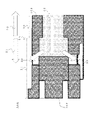
- FIG. 8 is a diagram showing an example of the valve open state. Note that FIG. 8 is a cross-sectional view similar to FIG. In the drawing, the pressure higher than the valve opening pressure is simply indicated as "valve opening pressure 63".
- valve open state the state shown in FIG. 8 (hereinafter referred to as the "valve open state") is different in that the oil pressure is higher than in the unseated state.
- the difference is that such pressure pushes the valve body 102 further than in the unseated state, moving the valve body 102 to the left from FIG.
- the valve open state differs in that the third space 33 is open and the oil is being discharged. That is, the valve open state differs from the unseated state in that the valve body 102 moves further in the first direction 21 .
- the third space 33 is connected to the first space 31 . Since the oil that has flowed into the first space 31 is pressurized, it is discharged from the third space 33 to the outside.
- the relief valve 100 opens and closes by switching between an open state and another closed state (the above-described unseated state or seated state). In this manner, the relief valve 100 switches whether to discharge the oil to the outside.
- the relief valve 100 can suppress the pressure difference before and after opening, that is, the hysteresis. Specifically, the results are as follows.
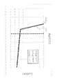
- FIG. 9 is a diagram showing experimental results.
- the horizontal axis indicates the discharge pressure (unit: kilopascal).
- the vertical axis indicates the oil flow rate (the unit is liters per minute).
- a first graph 501 shows the time when the valve is closed.
- a second graph 502 indicates the time when the valve is open.
- a first graph 501 and a second graph 502 are graphs showing characteristics of the relief valve 100 configured as shown in FIG. 5 and the like.
- the change in the discharge pressure with respect to the flow rate is almost the same both when the valve is open and when the valve is closed. In this way, since the pressure changes are substantially the same, the relief valve 100 configured as shown in FIG.
- the relief valve 100 can be made smaller. Further, with the above configuration, the relief valve 100 can have a simple structure.
- a stepped portion or a tapered portion may be further formed in the boundary 34 or the second space portion 32 .
- each component of the relief valve may be changed according to the valve opening pressure.
- the size, shape, positional relationship, etc. of each hole may be other than the illustrated example.
- Comparative Example 600 a relief valve (hereinafter simply referred to as "Comparative Example 600") as a comparative example will be described as an example.
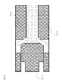
- FIG. 10 is a diagram showing the valve closed state of the comparative example.
- the comparative example 600 is different in that there is no step or the like at the boundary. Moreover, the comparative example 600 is different in that it is configured to seal with the abutment surface 603 .
- the valve is closed by the valve body 601 and the valve seat 602 when the pressure is low and the valve is closed. Then, when the pressure increases, the comparative example 600 opens as follows.
- FIG. 11 is a diagram showing the valve open state of the comparative example.
- FIG. 11 is different in that the valve body 601 is separated from the valve seat 602 by oil pressure from the valve closed state.
- Comparative Example 600 With a configuration like Comparative Example 600, the difference in the pressure receiving area before and after the valve is opened tends to increase. Therefore, hysteresis, which is the pressure difference between the valve opening operation and the valve closing operation, tends to increase. Specifically, using Comparative Example 600 yields the following results.
- FIG. 12 is a diagram showing experimental results according to a comparative example. The horizontal and vertical axes are the same as in FIG.
- a third graph 605 indicates the time when the valve is closed.
- a fourth graph 606 indicates when the valve is open.
- a third graph 605 and a fourth graph 606 are graphs showing the characteristics of the comparative example 600 shown in FIG. 10 and the like.
- the material forming the first space 31 is a material that expands more easily depending on the temperature than the material of the valve body 102, the temperature inside the relief valve 100 or around the relief valve 100 becomes high. , gaps are likely to occur. If there is such a gap, oil is likely to leak from the gap. On the other hand, if the coefficients of linear expansion are the same or the difference between the coefficients of linear expansion is 20% or less, a gap is less likely to occur even if there is a temperature change.
- the same material is used for the material of the valve body 102 and the material forming the first space 31 and the like.
- a combination of materials having close coefficients of linear expansion may be used.
- a practical metal such as aluminum is used for both the material of the valve body 102 and the material forming the first space 31 and the like.
- aluminum "A6061" JIS designation
- JIS designation is a material with a coefficient of linear expansion of 23.6 ⁇ 10 ⁇ 6 .
- the material of the valve body 102 and the material forming the first space 31 and the like are aluminum (for example, "A2017”, “A5052”, “A5056”, or “A7075”) and brass. (For example, “C2801", “C3604", or “C2700"), copper (for example, “C1100” or “C1020”), brass, stainless steel (for example, SUS300 series) austenitic) and copper, stainless steel and brass, aluminum and magnesium alloys (such as "AZ31” or "AZ91”), or cast iron and titanium.
- the material for the valve body 102 and the material for forming the first space 31 and the like are cast iron, structural steel (for example, "SS400"), carbon steel (for example, "S45C”), and the like. ), tool steel (for example, "SKS3" or “SKD11”), and stainless steel (for example, SUS400 series martensite).
- the difference in coefficient of linear expansion is about 12% or less, and the difference in coefficient of linear expansion can be reduced.
- the oil pump has, for example, a pump case and a pump rotor as described below.
- FIG. 13 is a diagram showing a configuration example of a pump case and a pump rotor.
- the oil pump 1 has a pump case 701 and a pump rotor 703 as shown.
- the figure is a sectional view of a pump case 701 and a pump rotor 703 .
- the pump rotor 703 contacts, for example, the inner wall of the pump case 701 (hereinafter simply referred to as the "inner wall portion 702") as illustrated.
- FIG. 14 is a diagram showing an example of a contact portion between a pump case and a pump rotor.
- the figure is a cross-sectional view showing a cross section of "AA" shown in FIG.
- the illustrated portion is the contact portion between the pump case 701 and the pump rotor 703 (hereinafter simply referred to as "contact portion 704"). becomes.
- the contact portion 704 will be enlarged and explained below.
- FIG. 15 is a diagram showing an example of a contact portion.
- the contact portion 704 may be chamfered to form a chamfered portion 705 as shown in the figure.
- chamfered portion 705 may also be formed at other locations.
- Such a chamfered portion 705 may become a gap.
- foreign matter may enter into the gap.
- foreign matter enters the oil path or an intrusion path such as parts brought in during assembly.
- the foreign matter is, for example, metal such as cutting burrs. If a foreign object is inserted into the chamfered portion 705 or the like and pushed into the chamfered portion 705, the oil pump 1 may be locked. In particular, the oil pump 1 is likely to lock when it is pushed in with high hydraulic pressure. Therefore, the following configuration is adopted to deal with such contamination by foreign matter.
- FIG. 16 is a diagram showing an example of groove formation.
- the figure is a cross-sectional view similar to FIG.
- grooves 706 are formed in pump case 701 at locations as shown.
- the groove 706 is formed in a direction perpendicular to the circumference of the pump case 701 so as to connect with the pump case 701 and the inner wall portion 702 and lead to the outside of the pump case 701 . That is, groove 706 is formed in pump case 701 so that chamfered portion 705 communicates with the outside of pump case 701 .
- the grooves 706 are formed in six locations at substantially equal intervals in a direction perpendicular to the circumference of the pump case 701 so that the outside of the pump case 701 and the inner wall portion 702 communicate with each other. .
- grooves 706 need not have the illustrated intervals, positions, arrangements, and number of formations. That is, grooves 706 may be formed at positions other than those shown. For example, grooves 706 may be formed in more or less than six locations.
- the number of grooves 706 formed increases, the amount of oil released tends to increase. Therefore, it is desirable to determine the number of grooves 706 to be formed according to the permissible amount of oil discharge. Therefore, for example, when a large amount of oil discharge can be tolerated, it is desirable to form a large number of grooves 706 . In this way, if the number of grooves 706 to be formed is determined within the range of the allowable amount of oil to be discharged, it is possible to prevent excessive oil from being discharged from the grooves 706 .
- grooves 706 need not be arranged symmetrically as shown.
- groove 706 is preferably located on the discharge side (ie, on the high pressure side). Further, the groove 706 may be arranged not on the suction side.
- the groove 706 on the suction side tends to increase the possibility of sucking air, foreign matter, or both from the groove 706 . Therefore, it is desirable that the grooves 706 are arranged centrally on the discharge side and less on the suction side.
- the groove 706 By arranging the groove 706 mainly on the discharge side in this way, the possibility that foreign matter or the like enters from the groove 706 can be reduced.
- the oil pump 1 may be provided with markings such as, for example:
- FIG. 17 is a diagram showing an example of mark installation.
- the mark 801 may be placed at the following positions.
- the mark 801 is, for example, an identification mark. Also, the mark 801 is formed on the surface of the oil pump 1 . Specifically, the mark 801 has a concave shape. That is, the mark 801 is formed by a depression or the like. With such a mark 801, the front and back of the trochoid pump can be identified. Note that the mark 801 may also be applied to an oil pump such as a vane-pump, for example.
- the mark 801 Since the mark 801 has a concave shape, if it is on the oil flow path (hereinafter simply referred to as "flow path 802"), foreign matter may be sucked in.
- the flow path 802 is a hatched area in the figure.
- the foreign matter is, for example, metal such as cutting burrs.
- the foreign matter may be caught between the intake and discharge ports.
- the oil pump 1 may lock when such a foreign object is caught.
- the mark 801 be formed outside the outer diameter line of the port (hereinafter simply referred to as "outer diameter line 803"). That is, when the mark 801 is formed outside the outer diameter line 803, the probability that the mark 801 will suck in foreign matter can be reduced. Therefore, it is possible to reduce so-called jamming of foreign matter (that is, foreign matter being pinched). Therefore, locking of the oil pump 1 due to foreign matter can be reduced.
- the outer diameter line 803 is, for example, a line that matches the root diameter of the outer of the pump gear.
- embodiments are such as pump covers with relief valves.
- the pump cover is used for, for example, a trochoid type oil pump.
- each element may have a shape or number other than those described above.
- Oil pump 10 Pump cover 12 : Hole 21 : First direction 22 : Second direction 31 : First space 32 : Second space 33 : Third space 34 : Boundary 41 : First diameter 42 : Third 2 Diameter 51 : Inflow port 61 : Second pressure 62 : First pressure 63 : Valve opening pressure 100 : Relief valve 101 : Spring 102 : Valve body 103 : Housing 104 : Seal portion 201 : First surface 202 : Second surface 701 : pump case 702 : inner wall portion 703 : pump rotor 704 : contact portion 705 : chamfered portion 706 : groove 801 : mark 802 : flow path 803 : outer diameter line
Landscapes
- Engineering & Computer Science (AREA)
- General Engineering & Computer Science (AREA)
- Mechanical Engineering (AREA)
- Physics & Mathematics (AREA)
- Fluid Mechanics (AREA)
- Safety Valves (AREA)
- Details And Applications Of Rotary Liquid Pumps (AREA)
Abstract
ヒステリシスを抑制する。弁体の移動によりオイルを吐出するか否かを切り替えるリリーフバルブが、前記弁体が移動する第1空間部と、前記第1空間部とつながり、かつ、前記第1空間部より小さい径である第2空間部と、前記弁体に接する弾性体と、前記弁体の円周方向に設置するシール部と、前記第1空間部に形成される第3空間部とを有する。
Description
本発明は、リリーフバルブに関する。
ポンプ等において、オイル等の液体に対し、一定以上の圧力がかかるのを防ぐため、液体を逃がすリリーフバルブ(「安全弁」(relief valve、safety valve)、又は、「逃し弁」等という場合もある。)が知られている。具体的には、ソレノイドバルブ及び圧力センサを取り付けたポンプカバーにおいて、電磁式のクラッチにより、開閉部の位置を調整して吸入口の開閉を制御する。そして、吸入口を開閉する制御に基づいて吸入口を開くと、吸入口と吐出口が連通状態となり、流路を流れるオイルは、吸入口及び吐出口を通って吐出する。このようにして、ソレノイドバルブは、開閉によって、流路に流れるオイルの一部を他の流路へ流れるように調整する。例えば、このような技術が知られている(例えば、特許文献1等)。
特許文献1に開示の技術では、リリーフバルブ等に対する圧力が高い場合には、ヒステリシス(Hysteresis)が大きくなりやすい。したがって、従来の技術は、ヒステリシスを考慮して設計すると、リリーフバルブが大型化、又は、スプリング等といったリリーフバルブを構成する部品の耐久性が保証できない等の課題がある。
本発明は、上記に示す事情に鑑みてなされたもので、ヒステリシスを抑制できるリリーフバルブを提供することを目的とする。
本発明は、弁体の移動によりオイルを吐出するか否かを切り替えるリリーフバルブであって、
前記弁体が移動する第1空間部と、
前記第1空間部とつながり、かつ、前記第1空間部より小さい径である第2空間部と、
前記弁体に接する弾性体と、
前記弁体の円周方向に設置するシール部と、
前記第1空間部に形成される第3空間部と
を有することを特徴とする。
前記弁体が移動する第1空間部と、
前記第1空間部とつながり、かつ、前記第1空間部より小さい径である第2空間部と、
前記弁体に接する弾性体と、
前記弁体の円周方向に設置するシール部と、
前記第1空間部に形成される第3空間部と
を有することを特徴とする。
本発明によれば、ヒステリシスを抑制できるリリーフバルブを提供できる。
以下、図面を参照しつつ、本発明の実施形態を説明する。
[第1実施形態]
図1は、オイルポンプの例を示す図である。以下、図示するようなオイルポンプ1を例に説明する。なお、リリーフバルブの詳細は、別の図で説明する。また、リリーフバルブは、図示するようなオイルポンプ1以外に用いられてもよい。例えば、リリーフバルブは、ある程度の粘度があるオイルを扱うオイルポンプであれば適用できる。また、オイルポンプの大きさ等は問わない。
図1は、オイルポンプの例を示す図である。以下、図示するようなオイルポンプ1を例に説明する。なお、リリーフバルブの詳細は、別の図で説明する。また、リリーフバルブは、図示するようなオイルポンプ1以外に用いられてもよい。例えば、リリーフバルブは、ある程度の粘度があるオイルを扱うオイルポンプであれば適用できる。また、オイルポンプの大きさ等は問わない。
例えば、オイルポンプ1は、-40℃乃至120℃の環境等で使用できるオイルポンプである。
また、リリーフバルブは、Oリング等のシール部材を更に備えてもよい。以下、説明の簡略化のため、簡易な構成で説明する。
例えば、リリーフバルブは、オイルポンプ1に対して設置するポンプカバー10と一体となって設置される。このように、ポンプカバー10は、リリーフバルブを有する構成であるのが望ましい。ポンプカバー10がリリーフバルブを有すると、リリーフバルブを有さないオイルポンプにも容易にリリーフバルブを換装できる。また、ポンプカバー10と一体にすると、省部品化により、省スペース化ができる。
以下、ポンプカバー10、及び、リリーフバルブが一体の例で説明する。具体的には、ポンプカバー10は、オイルポンプ1に対して以下のように設置される。
図2は、ポンプカバーの設置例を示す図である。例えば、図示するように、ポンプカバー10は、オイルポンプ1の最下部(図におけるZ軸方向において最も下側をいう。なお、Z軸方向は、例えば、重力方向である。)等に設置される。なお、ポンプカバー10の設置位置、向き、及び、範囲等は、図示する形式に限られない。すなわち、ポンプカバー10は、例えば、オイルポンプ1の最下部以外に設置されてもよい。
このように、ポンプカバー10は、オイルポンプ1の本体となる部品に対してねじ止め等で取り付けられる。
オイルポンプ1は、オイルを吸い上げる、及び、オイルを所定の位置へ送る等といった動作を行う。このような動作において、リリーフバルブは、ポンプの吐出圧力がリリーフバルブのセット圧を超えた場合に、オイルを外部へ吐出する。このように、オイルポンプ1は、ポンプの吐出圧力がリリーフバルブのセット圧を超えた場合に、リリーフバルブを作動させて、オイルを外部に排出する。ゆえに、オイルポンプ1は、ポンプの吐出側における圧力(例えば、ポンプの吐出配管、又は、ケーシング内の圧力等である。)を所定圧以下に抑えられる。
なお、リリーフバルブがオイルを外部へ排出する圧力、すなわち、リリーフバルブがオイルを外部へ吐出するように動作する基準となる圧力は、耐圧強度等を考慮して事前に設定される。以下、このように、リリーフバルブがオイルを外部へ排出する圧力を「開弁圧」(「セット圧」、又は、「クラッキング圧力」等という場合もある。)という。
また、リリーフバルブによるオイルの吐出先は、例えば、オイルポンプ1の外部(ドレーン等を含む。)等である。ただし、リリーフバルブによるオイルの吐出先は、吸入側に戻してもよい。
したがって、開弁圧は、ポンプ吐出側の配管、又は、機器類の耐圧等に応じて設定される値である。
[リリーフバルブの構成例]
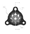
図3は、リリーフバルブを有するポンプカバーの例を示す第1図である。
図3は、リリーフバルブを有するポンプカバーの例を示す第1図である。
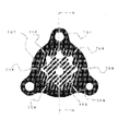
図4は、リリーフバルブを有するポンプカバーの例を示す第2図である。
図3及び図4は、図3が主に示すポンプカバー10の面(以下「おもて面」とする。)に対して、図4が逆の面(以下「裏面」とする。)を主に示す関係である。
例えば、図示するような位置に、リリーフプレート11が設置される。また、図示する例は、ポンプカバー10が穴12を有する。このような穴12により、オイルが外部へ排出される。なお、リリーフプレート11及び穴12の位置、大きさ、及び、形状等は図示する例に限られない。
図示するポンプカバー10において、リリーフバルブは、例えば、以下のような構成である。
図5は、リリーフバルブの例を示す図である。図は、ポンプカバー10におけるリリーフバルブ100となる一部を示す断面図である。なお、以下に示す断面図は、図1に「A-A」で示す断面を示す図である。
リリーフバルブ100は、例えば、ばね101、弁体102、筐体103、及び、シール部104等で構成する。なお、リリーフバルブ100は、重力方向と一致する向きであるのが望ましい。このような向きであると、リリーフバルブ100の傾きが抑制されやすく、リリーフバルブ100をスムーズに摺動できる。
ばね101は、弾性体の例である。具体的には、ばね101は、弁体102(図は、弁体102の左側にばね101を設置する例を示す。)に接するように設置する。
また、以下の説明は、弁体102が図において左右方向に移動する例で説明する。そして、以下の説明は、図における左方向を「第1方向21」とする。一方で、図における右方向を「第2方向22」とする。
また、以下の例では、ばね101は、第1方向21、及び、第2方向22に伸び縮みする。具体的には、弁体102に対し、右方向から力が加えられると、ばね101は、第1方向21に縮む。そして、弁体102に加える力が弱くなると、ばね101は、第2方向22に伸びる。すなわち、ばね101は、復元力で第2方向22に弁体102を押して移動させる。したがって、弁体102は、ばね101の伸び縮みにより、第1方向21、及び、第2方向22に往復移動する。
このように、弾性体は、復元力によって弁体102を移動させる力を発する物体であればよい。したがって、弾性体は、ばね101以外の物体、又は、ばね101と他の物体の組み合わせ等であってもよい。ただし、弾性体は、耐油性、耐熱性、耐久性、及び、圧縮量等からすると、ばねであるのが望ましい。
筐体103は、第1空間部31、第2空間部32、及び、第3空間部33等を有する形状である。具体的には、図示する例において、左側の空間部が第1空間部31となり、かつ、右側の空間部が第2空間部32となる。
第1空間部31は、弁体102を内設し、弁体102が長手方向に往復移動する空間部である。したがって、第1空間部31の径(以下「第1径41」という。また、図は、上下方向が径方向である。)は、弁体102、又は、ばね101の径等に応じて異なる大きさである。また、第1方向21、及び、第2方向22は、第1空間部31の長手方向と一致する。
第2空間部32は、第1径41より小さい径(以下「第2径42」という。)の空間部である。このように、第2径42が第1径41より小さい径であるため、第1空間部31、及び、第2空間部32の境界(以下単に「境界34」という。)は、例えば、第1空間部31より狭い径となるため、段差となる。
また、第1空間部31、及び、第2空間部32は、隣接し、互いにつながる空間部である。図示する例では、第1空間部31の右端が第2空間部32の左端部と一致し、第1空間部31、及び、第2空間部32の両空間部は、つながる空間部である。したがって、第2空間部32は、オイルポンプ1の本体から第1空間部31へオイルを流入させる流路となる。
第2空間部32には、例えば、図示するような位置に流入口51を有する。そして、流入口51は、オイルポンプ1の本体から流れるオイルが第2空間部32に流入する経路となる。具体的には、オイルは、図において下側から上側に向かって、流入口51から第2空間部32に流入する。したがって、オイルが流入口51から第2空間部32に大量に流入する、又は、高い圧力で流入すると、弁体102には、第1方向21に高い圧力がかかる。
また、第2空間部32に流入したオイル、及び、ばね101は、弁体102に対し、対向する面に力をかける位置関係となる。具体的には、第2空間部32、及び、ばね101は、弁体102を挟んで図における左右対称に設置する位置関係となる。すなわち、第2空間部32に流入したオイル、及び、ばね101は、弁体102の左右反対となる端部に対して力をかける。
以下、弁体102の端部のうち、第1空間部31、及び、第2空間部32がつながる方(図では、右側である。)の端部を「第1端部」という。一方で、第1端部とは異なる端部(図では、左側である。)の端部を「第2端部」という。
そして、以下の説明では、弁体102が有する面のうち、第1端部側に形成される面を「第1面201」という。一方で、弁体102が有する面のうち、第2端部側に形成される面を「第2面202」という。したがって、第1面201、及び、第2面202は、弁体102において、互いに反対となる面の位置関係である。
ばね101は、例えば、第2面202に接するように設置される。したがって、ばね101による復元力は、第2面202に対してかけられる。ゆえに、復元力が第2面202にかけられる(図では、左から右向きの力となる。)ため、弁体102は、復元力によって第2方向22に移動する。
一方で、第2空間部32に流入したオイルは、第1面201に対して圧力をかける。したがって、オイルによって圧力が第1面201にかけられる(図では、右から左向きの力となる。)ため、弁体102は、オイルによる圧力によって第1方向21に移動する。
第3空間部33は、第1空間部31に形成される穴である。例えば、第3空間部33は、第1空間部31に対して垂直方向に開口するように形成される。すなわち、第1空間部31は、第3空間部33によって外部とつながる。例えば、第3空間部33は、第1空間部31における上部及び下部の2箇所に形成される。
したがって、リリーフバルブ100は、弁体102を第1方向21に移動させ、第3空間部33を開口する(図の構成では、第3空間部33より左側に弁体102を移動させると開口する。)と、オイルを外部へ吐出できる。
一方で、リリーフバルブ100は、弁体102を第2方向22に移動させ、弁体102で第3空間部33を塞ぐ(図では、第3空間部33より右側に弁体102を移動させると第3空間部33を塞ぐ。)と、オイルを外部へ吐出しないようにできる。
このように、リリーフバルブ100は、弾性体の復元力とオイルの圧力の力関係により、弁体102を往復移動させて第3空間部33の開閉を切り替える。したがって、第3空間部33の位置(図では、左右方向の位置である。)等は、開閉させたい圧力等の関係によって定まる。ゆえに、第3空間部33の位置は、ばねの弾性係数、開弁圧、及び、バルブの径等により定まる。また、第3空間部33の形状、数、及び、径は、オイルを吐出させる量、すなわち、オイルの吐出による圧力の低下量等によって定まる。
シール部104は、例えば、図示するような位置において、弁体102の外径をシール(seal)する。具体的には、シール部104は、弁体102の円周方向に設置する。すなわち、シール部104は、弁体102が往復移動する方向(図では、左右方向である。)に対し、垂直方向に設置される。また、シール部104の設置位置は、オイルの圧力を主に受ける第1面201に対し、側面となる位置である。
例えば、シール部104は、第3空間部33から1ミリメートル以上程度の長さである。すなわち、第3空間部33から境界34までは、1ミリメートル以上程度の長さである。
このような位置に設置されるシール部104、及び、第1空間部31の壁部により、第1空間部31に流入するオイルは、シールされる。この例では、オイルは、第1空間部31において、シール部104より左側に流れない状態となる。
図示する状態は、第2空間部32にオイルが流入していない、又は、第2空間部32にオイルが流入していてもばね101による復元力より弱い圧力しか発しない状態である。また、この状態は、ばね101が弁体102を押す力(すなわち、第2方向22の向きの力である。)より、オイルによる圧力で弁体102を押す力(すなわち、第1方向21の向きの力である。)の方が弱い強弱関係である。つまり、この状態は、弁体102を右側から左側へ押す力より、弁体102を左側から右側に押す力の方が強い状態である。
このような状態では、図示するように、弁体102は、境界34に形成される段差に突き当てられた状態(すなわち、第2方向22に力がかかっていても、境界34より右側に進まない状態である。)となる。
以下、このように弁体102が境界34で止まっている状態を「着座状態」という。また、着座状態は、オイルによる圧力がばね101の復元力と比較して、弁体102を段差から離すほど強くない状態である。
一方で、オイルによる圧力が高まり、オイルによる圧力が一定以上になると、弁体102は、境界34より第1方向21に移動する。
以下、オイルによる圧力が開弁圧未満であり、かつ、弁体102が移動しだすオイルによる圧力を「第1圧力」という。また、以下の説明では、第1圧力未満の圧力(第2空間部32にオイルが流入していない状態であって、オイルによる圧力が「0」の場合を含む。)を総じて「第2圧力」という。
したがって、第1圧力未満の圧力、すなわち、第2圧力である場合には、弁体102は、着座状態となる。
図6は、着座状態の例を示す図である。図6は、断面図であって、図5と同様の内容を簡易に示す図である。なお、図には、第2圧力61を模式的に記載する。また、図の簡略化のため、図6は、流入口51等の記載を省略する。
着座状態は、少なくとも第1空間部31にはオイルが流入していない状態である。すなわち、着座状態は、第2空間部32が弁座となり、弁体102、及び、弁座によって、オイルが第1空間部31に流入するのを塞ぐ状態である。また、着座状態は、第3空間部33が塞がり、オイルが吐出しない状態でもある。
上記のような着座状態に対し、オイルの圧力の変化によって、リリーフバルブ100は、以下のような離座状態、又は、開弁状態に変化する。
[離座状態の例]
図7は、離座状態の例を示す図である。なお、図7は、図6と同様に、断面図である。なお、図には、開弁圧未満、かつ、第1圧力以上の圧力を単に「第1圧力62」と模式的に記載する。また、図の簡略化のため、図7は、ばね101が縮んでいる状態等の記載を省略する。
図7は、離座状態の例を示す図である。なお、図7は、図6と同様に、断面図である。なお、図には、開弁圧未満、かつ、第1圧力以上の圧力を単に「第1圧力62」と模式的に記載する。また、図の簡略化のため、図7は、ばね101が縮んでいる状態等の記載を省略する。
例えば、第1圧力62は、「開弁圧-シール部長さ×ばね定数÷シール部の断面積」の計算で求まる圧力である。
着座状態と比較すると、まず、図7に示すような状態(以下「離座状態」という。)は、オイルが第2空間部32から第1空間部31に流入し、着座状態よりオイルによる圧力が高い状態である点が異なる。このように、オイルの流入により、離座状態は、圧力で弁体102が押され、図6より弁体102が左側へ移動している点が異なる。その結果、離座状態は、弁体102が段差から離れている状態である点が異なる。すなわち、離座状態は、着座状態より弁体102が第1方向21に移動している点が異なる。
図示するように、開弁圧未満、かつ、第1圧力以上の圧力であると、弁体102は、第1方向に移動する。ただし、オイルによる圧力は、開弁圧未満の圧力であるため、第3空間部33は、塞がれた状態である。すなわち、離座状態は、オイルがシールされている状態である。そのため、オイルは、外部に吐出しない状態である。
このような離座状態において、圧力が弱まると、弁体102は、ばね101の復元力により、第2方向22に移動する。そして、圧力が第2圧力まで下がると、状態は、着座状態に戻る。一方で、離座状態より更に圧力が高まり、開弁圧以上の圧力になると、リリーフバルブ100は、以下のような開弁状態となる。
[開弁状態の例]
図8は、開弁状態の例を示す図である。なお、図8は、図7と同様に、断面図である。なお、図には、開弁圧以上の圧力を単に「開弁圧63」と模式的に記載する。
図8は、開弁状態の例を示す図である。なお、図8は、図7と同様に、断面図である。なお、図には、開弁圧以上の圧力を単に「開弁圧63」と模式的に記載する。
着座状態と比較すると、まず、図8に示すような状態(以下「開弁状態」という。)は、離座状態よりオイルによる圧力が更に高い状態である点が異なる。このような圧力により、圧力で離座状態より更に弁体102が押され、図7より弁体102が左側へ移動している点が異なる。その結果、開弁状態は、第3空間部33が開口し、オイルが吐出されている状態である点が異なる。すなわち、開弁状態は、離座状態より弁体102が更に第1方向21に移動している点が異なる。
オイルによる圧力が開弁圧以上に強くなると、第3空間部33は、第1空間部31とつながった状態となる。そして、第1空間部31に流入したオイルは、圧力がかかっているため、第3空間部33より外部へ吐出される。
以上のように、リリーフバルブ100は、開弁状態と、それ以外の閉弁状態(上記の離座状態又は着座状態である。)を切り替えることで開弁及び閉弁を行う。このようにして、リリーフバルブ100は、オイルを外部へ吐出する動作とするか否かを切り替える。
このような構成であると、オイルを吐出するか否かの切り替え、すなわち、開放の前後で径の差が少ない。このように、圧力を受ける面積の差を少なくできるため、リリーフバルブ100は、開放の前後の圧力差、すなわち、ヒステリシスを抑制できる。具体的には、以下のような結果となる。
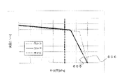
図9は、実験結果を示す図である。図は、横軸に吐出圧(単位は、キロパスカルである。)を示す。そして、縦軸にオイルの流量(単位は、リットル毎分である。)を示す。
第1グラフ501は、閉弁時を示す。
第2グラフ502は、開弁時を示す。
第1グラフ501、及び、第2グラフ502は、図5等に示す構成によるリリーフバルブ100の特性を示すグラフである。
第1グラフ501、及び、第2グラフ502が示すように、開弁時と閉弁時のどちらの場合においても、流量に対する吐出圧の変化がほとんど同一である。このように、圧力の変化がほぼ同一であるため、図5等に示す構成によるリリーフバルブ100は、ヒステリシス、すなわち、開弁時と閉弁時の圧力差を抑制できる。
また、以上のようなシール部104の構成であると、リリーフバルブ100を小型化できる。また、以上のような構成であると、リリーフバルブ100は、簡易な構造にできる。
なお、境界34、又は、第2空間部32には、段差又はテーパ部が更に形成されてもよい。
開弁圧に応じて、リリーフバルブが有する各構成要素は、種類等が変更されてもよい。例えば、各穴の大きさ、形状、又は、位置関係等は、図示する例以外であってもよい。
[比較例]
例えば、以下のような比較例となるリリーフバルブ(以下単に「比較例600」という。)を例に説明する。
例えば、以下のような比較例となるリリーフバルブ(以下単に「比較例600」という。)を例に説明する。
図10は、比較例の閉弁状態を示す図である。比較例600は、境界において段差等がない構成である点が異なる。また、比較例600は、突き当て面603でシールする構成である点が異なる。
図示するように、圧力が低い閉弁状態では、弁体601及び弁座602により閉弁する。そして、圧力が高まると、比較例600は、以下のように開弁状態となる。
図11は、比較例の開弁状態を示す図である。図11は、閉弁状態よりオイルの圧力によって弁体601が弁座602より離れる状態になる点が異なる。
比較例600のような構成であると、開弁前後で受圧面積の差が大きくなりやすい。そのため、開弁動作と閉弁動作の圧力差である、ヒステリシスが大きくなりやすい。具体的には、比較例600を用いると、以下のような結果となる。
図12は、比較例による実験結果を示す図である。横軸及び縦軸は図9と同様である。
第3グラフ605は、閉弁時を示す。
第4グラフ606は、開弁時を示す。
第3グラフ605、及び、第4グラフ606は、図10等に示す比較例600の特性を示すグラフである。
図11で説明する開弁前後で受圧面積が大きく変化するため、第3グラフ605に示す閉弁時の特性、及び、第4グラフ606に示す開弁時の特性の差が大きくなりやすい。そのため、ヒステリシスが大きくなりやすい。
[線膨張係数について]
弁体102の材料、及び、第1空間部31等を形成する材料は、線膨張係数が同一、又は、線膨張係数の差異が20%以下であるのが望ましい。すなわち、弁体102の材料、及び、第1空間部31等を形成する材料は、線膨張係数の差異が少なく、温度変化による伸縮が同程度であるのが望ましい。
弁体102の材料、及び、第1空間部31等を形成する材料は、線膨張係数が同一、又は、線膨張係数の差異が20%以下であるのが望ましい。すなわち、弁体102の材料、及び、第1空間部31等を形成する材料は、線膨張係数の差異が少なく、温度変化による伸縮が同程度であるのが望ましい。
例えば、第1空間部31を形成する材料が、弁体102の材料より、温度によって伸びやすい材料であると、リリーフバルブ100内、又は、リリーフバルブ100の周辺の温度が高くなった場合等に、隙間が生じやすい。このような隙間があると、隙間からオイルが漏れやすい。一方で、線膨張係数が同一、又は、線膨張係数の差異が20%以下であると、温度変化があっても、隙間が生じにくいため、リリーフバルブ100から、オイルが漏れるのを抑制できる。
例えば、線膨張係数を同一、又は、線膨張係数の差異を20%以下にするには、弁体102の材料、及び、第1空間部31等を形成する材料は、同一の材料を採用する、又は、線膨張係数が近しい材料の組み合わせを採用する等である。具体的には、弁体102の材料、及び、第1空間部31等を形成する材料のどちらにも、アルミニウム等の実用金属を採用する。例えば、アルミニウム「A6061」(JIS呼称である。)は、線膨張係数が23.6×10⁻⁶となる材料である。
例えば、弁体102の材料、及び、第1空間部31等を形成する材料は、アルミニウム(例えば、「A2017」、「A5052」、「A5056」、又は、「A7075」等である。)と真鍮(例えば、「C2801」、「C3604」、又は、「C2700」等である。)、銅(例えば、「C1100」、又は、「C1020」等である。)と真鍮、ステンレス鋼(例えば、SUS300番台のオーステナイト系である。)と銅、ステンレス鋼と真鍮、アルミニウムとマグネシウム合金(例えば、「AZ31」、又は、「AZ91」等である。)、又は、鋳鉄とチタン等の組み合わせである。なお、弁体102の材料、及び、第1空間部31等を形成する材料は、鋳鉄、構造用鋼(例えば、「SS400」等である。)、炭素鋼(例えば、「S45C」」等である。)、工具鋼(例えば、「SKS3」、又は、「SKD11」等である。)、及び、ステンレス鋼(例えば、SUS400番台のマルテンサイト系である。)の組み合わせ等でもよい。
以上のような材料の組み合わせとすると、線膨張係数の差異は、12%以下程度になり、線膨張係数の差異を小さくできる。
[第2実施形態]
オイルポンプは、例えば、以下のようなポンプケース、及び、ポンプロータを有する構成である。
オイルポンプは、例えば、以下のようなポンプケース、及び、ポンプロータを有する構成である。
図13は、ポンプケース、及び、ポンプロータの構成例を示す図である。例えば、オイルポンプ1は、図示するようなポンプケース701、及び、ポンプロータ703を有する。図は、ポンプケース701、及び、ポンプロータ703の断面図である。
ポンプロータ703は、例えば、図示するようにポンプケース701の内壁(以下単に「内壁部702」という。)と接触する。
以下、「A-A」の断面で説明する。
図14は、ポンプケース、及び、ポンプロータの接触部の例を示す図である。図は、図13に示す「A-A」の断面を示す断面図である。
このようにポンプケース701、及び、ポンプロータ703が接触する場合には、例えば、図示するような部分がポンプケース701、及び、ポンプロータ703の接触部(以下単に「接触部704」という。)となる。
以下、接触部704を拡大して説明する。
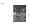
図15は、接触部の例を示す図である。例えば、接触部704において、図示するような箇所に面取り処理が行われ、面取部705が形成される場合がある。
なお、面取部705は、他の箇所にも形成されてもよい。
このような面取部705は、隙間となる場合がある。このように、隙間となると、異物が混入する場合がある。例えば、異物は、油路、又は、組み付けの際に部品が持ち込む等の侵入経路で混入する。また、異物は、例えば、切削バリ等の金属である。そして、異物が面取部705等に介在し、押し込まれると、オイルポンプ1は、ロックしてしまう場合がある。特に、高い油圧で押し込まれた場合等に、オイルポンプ1は、ロックしやすい。そこで、このような異物の混入に対し、以下のような構成にする。
図16は、溝の形成例を示す図である。図は、図13と同様の断面図である。例えば、溝706は、図示するような位置においてポンプケース701に形成される。
溝706は、ポンプケース701及び内壁部702と接続し、かつ、ポンプケース701の外部へ通じるように、ポンプケース701の円周に対して直交方向に形成される。すなわち、溝706は、面取部705とポンプケース701の外部が通じるようにポンプケース701に形成される。
例えば、図示する例のように、溝706は、ポンプケース701の円周に対して直交方向に、ほぼ等間隔で6箇所に、ポンプケース701の外部及び内壁部702が通じるように形成される。
このような溝706が形成されたポンプケース701であると、異物が混入しても、溝706を通って異物を外部に放出できる。
なお、溝706は、図示する間隔、位置、配置、及び、形成数でなくともよい。すなわち、溝706は、図示する位置以外に形成されてもよい。例えば、溝706は、6箇所より多く形成される、又は、少なく形成してもよい。
ただし、溝706の形成数が多くなると、オイルの放出量も増えやすい。したがって、溝706の形成数は、オイルの放出量の許容量等に応じて定めるのが望ましい。ゆえに、例えば、オイルの放出量が多く許容できる場合には、溝706の形成数は多いのが望ましい。このように、許容できるオイルの放出量の範囲で溝706の形成数が定まると、溝706から過剰にオイルが放出されるのを防ぐことができる。
また、溝706は、図示するように、対称の配置でなくともよい。例えば、溝706は、吐出側(すなわち、高圧側となる。)に配置されるのが望ましい。そして、溝706は、吸入側にない配置等でもよい。
吸入側に溝706を配置すると、空気、異物、又は、これらの両方を溝706から吸い込む可能性が高くなりやすい。したがって、溝706の配置は、吐出側を中心に配置し、吸入側には少なくする配置であるのが望ましい。
このように、溝706を主に吐出側に配置すると、溝706から異物等が入る可能性を少なくできる。
[第3実施形態]
トロコイドポンプ(trochoid pump)の場合には、オイルポンプ1に、例えば、以下のようなマークを設ける場合がある。
トロコイドポンプ(trochoid pump)の場合には、オイルポンプ1に、例えば、以下のようなマークを設ける場合がある。
図17は、マークの設置例を示す図である。例えば、マーク801は、以下のような位置等に設置される場合がある。
マーク801は、例えば、識別マーク等である。また、マーク801は、オイルポンプ1の表面に形成する。具体的には、マーク801は、凹形状である。すなわち、マーク801は、窪み等で形成される。このようなマーク801があると、トロコイドポンプの表裏を識別できる。なお、マーク801は、例えば、ベーンポンプ(vane-pump)等のオイルポンプに適用されてもよい。
マーク801は、凹形状であるため、オイルの流路(以下単に「流路802」という。)上にあると、異物を吸い込む場合がある。例えば、流路802は、図においてハッチングで示す範囲である。なお、異物は、例えば、切削バリ等の金属である。
このように、マーク801の部分に異物が吸い込まれると、異物は、吸入及び吐出のポートで挟まる場合がある。このような異物の挟まりが起きると、オイルポンプ1がロックする場合がある。
したがって、マーク801は、ポートの外径線(以下単に「外径線803」という。)より外に形成されるのが望ましい。すなわち、外径線803より外にマーク801が形成されると、マーク801が異物を吸い込む確率を下げることができる。そのため、いわゆる異物の噛み込み(すなわち、異物が挟み込まれることをいう。)を少なくできる。ゆえに、異物により、オイルポンプ1がロックするのを少なくできる。
外径線803は、例えば、ポンプギヤのアウターの歯底径と一致する線である。
[その他の実施形態]
例えば、実施形態は、リリーフバルブを有するポンプカバー等である。また、ポンプカバーは、例えば、トロコイド方式等のオイルポンプに用いる。
例えば、実施形態は、リリーフバルブを有するポンプカバー等である。また、ポンプカバーは、例えば、トロコイド方式等のオイルポンプに用いる。
実施形態は、上記に説明した以外の部品を有する構成で実施されてもよい。また、各要素は、上記に説明した以外の形状、又は、個数であってもよい。
以上、この発明の実施形態について図面を参照して詳述してきたが、具体的な構成はこの実施形態に限られるものではない。すなわち、この発明の要旨を逸脱しない範囲の設計等も権利内に含まれる。
1 :オイルポンプ
10 :ポンプカバー
12 :穴
21 :第1方向
22 :第2方向
31 :第1空間部
32 :第2空間部
33 :第3空間部
34 :境界
41 :第1径
42 :第2径
51 :流入口
61 :第2圧力
62 :第1圧力
63 :開弁圧
100 :リリーフバルブ
101 :ばね
102 :弁体
103 :筐体
104 :シール部
201 :第1面
202 :第2面
701 :ポンプケース
702 :内壁部
703 :ポンプロータ
704 :接触部
705 :面取部
706 :溝
801 :マーク
802 :流路
803 :外径線
10 :ポンプカバー
12 :穴
21 :第1方向
22 :第2方向
31 :第1空間部
32 :第2空間部
33 :第3空間部
34 :境界
41 :第1径
42 :第2径
51 :流入口
61 :第2圧力
62 :第1圧力
63 :開弁圧
100 :リリーフバルブ
101 :ばね
102 :弁体
103 :筐体
104 :シール部
201 :第1面
202 :第2面
701 :ポンプケース
702 :内壁部
703 :ポンプロータ
704 :接触部
705 :面取部
706 :溝
801 :マーク
802 :流路
803 :外径線
Claims (8)
- 弁体の移動によりオイルを吐出するか否かを切り替えるリリーフバルブであって、
前記弁体が移動する第1空間部と、
前記第1空間部とつながり、かつ、前記第1空間部より小さい径である第2空間部と、
前記弁体に接する弾性体と、
前記弁体の円周方向に設置するシール部と、
前記第1空間部に形成される第3空間部と
を有することを特徴とするリリーフバルブ。 - 前記弁体は、
前記第2空間部に流入する前記オイルによる圧力が開弁圧以上の圧力である場合には、前記第3空間部より前記第1空間部の長手方向における第1方向に移動して、前記オイルを前記第3空間部から吐出し、
前記第2空間部に流入する前記オイルによる圧力が前記開弁圧未満、かつ、第1圧力以上の圧力である場合には、前記第1方向に移動し、かつ、前記第3空間部を塞いで前記オイルが前記第3空間部から吐出しないようにし、
前記第2空間部に流入する前記オイルによる圧力が前記第1圧力未満である場合には、前記弾性体による復元力で第2方向に移動する
請求項1に記載のリリーフバルブ。 - 前記弁体の材料、及び、前記第1空間部を形成する材料は、
線膨張係数が同一、又は、線膨張係数の差異が20%以下である
請求項1又は2に記載のリリーフバルブ。 - 前記第1空間部、及び、前記第2空間部の境界には、前記第1空間部の径より径が狭くなる段差が形成され、
前記オイルによる圧力が第1圧力未満である場合には、前記弾性体による復元力で前記弁体が前記第2空間部で形成する弁座に突き当てられ、前記弁体及び前記弁座によって前記オイルが前記第1空間部に流入するのを塞ぎ、
前記オイルによる圧力が前記第1圧力以上である場合には、前記弁体は、第1方向に移動して前記段差から離れ、前記オイルが少なくとも前記第1空間部に流入する
請求項1乃至3のいずれか1項に記載のリリーフバルブ。 - 前記第1空間部と前記第2空間部は、
前記第1空間部の第1端部でつながり、
前記オイルは、
前記弁体が有する面のうち、前記第1端部の方に形成される第1面に対して圧力をかけ、
前記弾性体は、
前記弁体が有する面のうち、前記第1空間部の長手方向における前記第1端部とは異なる端部である第2端部の方に形成される第2面に対して復元力をかけ、
前記第3空間部は、
前記弾性体による復元力、及び、前記オイルによる圧力によって前記弁体が往復する第1方向、及び、第2方向に対して垂直方向に開口して形成される
請求項1乃至4のいずれか1項に記載のリリーフバルブ。 - 前記第1空間部は、
前記弁体を内設し、かつ、前記弁体が往復移動する空間であり、
前記第2空間部は、
前記第1空間部に隣接する空間であって、前記第1空間部へ前記オイルを流入させる流路となり、
前記第3空間部は、
前記第1空間部と外部をつなぐ穴であり、前記オイルによる圧力が開弁圧以上の圧力である場合には、前記第1空間部に流入する前記オイルを外部へ吐出させ、
前記弾性体は、
前記弁体が往復移動する方向に伸び縮みするばねであり、
前記オイルによる圧力によって縮み、
前記弾性体が伸びると、前記弁体に対して復元力がかかり、
前記弁体は、
前記弾性体による復元力、及び、前記オイルによる圧力の強弱関係に応じて前記第1空間部における長手方向を往復移動し、前記第2空間部から前記第1空間部へ前記オイルを流入させるか否かを切り替え、
前記シール部は、
前記弁体が往復移動する方向に対して垂直方向に設置される
請求項1乃至5のいずれか1項に記載のリリーフバルブ。 - 前記第1空間部と前記第2空間部の境界、又は、前記第2空間部には、
前記第1空間部の径より径が狭くなる段差、又は、テーパ部が形成される
請求項1乃至6のいずれか1項に記載のリリーフバルブ。 - 請求項1乃至7のいずれか1項に記載のリリーフバルブを有する
ポンプカバー。
Priority Applications (2)
| Application Number | Priority Date | Filing Date | Title |
|---|---|---|---|
| US18/010,210 US12085180B2 (en) | 2021-01-22 | 2021-12-16 | Relief valve and pump cover |
| CN202180043124.6A CN115917198A (zh) | 2021-01-22 | 2021-12-16 | 泄放阀 |
Applications Claiming Priority (2)
| Application Number | Priority Date | Filing Date | Title |
|---|---|---|---|
| JP2021008844A JP2022112848A (ja) | 2021-01-22 | 2021-01-22 | リリーフバルブ |
| JP2021-008844 | 2021-01-22 |
Publications (1)
| Publication Number | Publication Date |
|---|---|
| WO2022158182A1 true WO2022158182A1 (ja) | 2022-07-28 |
Family
ID=82548343
Family Applications (1)
| Application Number | Title | Priority Date | Filing Date |
|---|---|---|---|
| PCT/JP2021/046413 Ceased WO2022158182A1 (ja) | 2021-01-22 | 2021-12-16 | リリーフバルブ |
Country Status (4)
| Country | Link |
|---|---|
| US (1) | US12085180B2 (ja) |
| JP (1) | JP2022112848A (ja) |
| CN (1) | CN115917198A (ja) |
| WO (1) | WO2022158182A1 (ja) |
Citations (2)
| Publication number | Priority date | Publication date | Assignee | Title |
|---|---|---|---|---|
| JPH03107592A (ja) * | 1989-09-20 | 1991-05-07 | Yamada Seisakusho:Kk | オイルポンプのリリーフ弁構造 |
| JP2015218651A (ja) * | 2014-05-16 | 2015-12-07 | 株式会社ミツバ | 電動ポンプおよび車両用油圧回路 |
Family Cites Families (13)
| Publication number | Priority date | Publication date | Assignee | Title |
|---|---|---|---|---|
| US3796228A (en) * | 1972-08-25 | 1974-03-12 | A Bedo | Relief valve |
| JPH0442552Y2 (ja) * | 1986-07-21 | 1992-10-07 | ||
| US5921274A (en) * | 1996-06-10 | 1999-07-13 | Corken, Inc. | Internal relief and bypass valve for pumps and piping systems |
| JP3643311B2 (ja) * | 2000-03-03 | 2005-04-27 | 本田技研工業株式会社 | リリーフ弁構造 |
| CN100381697C (zh) * | 2004-10-13 | 2008-04-16 | 株式会社电装 | 燃料压力调节阀 |
| WO2007016780A1 (en) * | 2005-08-09 | 2007-02-15 | Stackpole Limited | Pressure relief valve |
| JP2011220394A (ja) * | 2010-04-06 | 2011-11-04 | Toyota Motor Corp | リリーフバルブ、並びに同リリーフバルブを具備する潤滑油供給装置及び油圧供給装置及びポンプユニット |
| JP5781800B2 (ja) * | 2011-03-27 | 2015-09-24 | 株式会社山田製作所 | リリーフ弁装置 |
| US8720849B2 (en) * | 2011-03-31 | 2014-05-13 | Magna Powertrain Inc. | Low gain pressure relief valve for a fluid pump |
| JP3179269U (ja) * | 2012-08-02 | 2012-10-25 | 株式会社山田製作所 | リリーフバルブ |
| JP2017044280A (ja) * | 2015-08-27 | 2017-03-02 | アイシン精機株式会社 | 油圧制御装置およびリリーフ弁 |
| WO2018173826A1 (ja) | 2017-03-23 | 2018-09-27 | 日本電産トーソク株式会社 | オイルポンプ |
| US10767776B2 (en) * | 2017-10-09 | 2020-09-08 | Cyrus Shank Corporation | Pressure relief valve with stop |
-
2021
- 2021-01-22 JP JP2021008844A patent/JP2022112848A/ja active Pending
- 2021-12-16 US US18/010,210 patent/US12085180B2/en active Active
- 2021-12-16 WO PCT/JP2021/046413 patent/WO2022158182A1/ja not_active Ceased
- 2021-12-16 CN CN202180043124.6A patent/CN115917198A/zh active Pending
Patent Citations (2)
| Publication number | Priority date | Publication date | Assignee | Title |
|---|---|---|---|---|
| JPH03107592A (ja) * | 1989-09-20 | 1991-05-07 | Yamada Seisakusho:Kk | オイルポンプのリリーフ弁構造 |
| JP2015218651A (ja) * | 2014-05-16 | 2015-12-07 | 株式会社ミツバ | 電動ポンプおよび車両用油圧回路 |
Also Published As
| Publication number | Publication date |
|---|---|
| CN115917198A (zh) | 2023-04-04 |
| US12085180B2 (en) | 2024-09-10 |
| JP2022112848A (ja) | 2022-08-03 |
| US20230296184A1 (en) | 2023-09-21 |
Similar Documents
| Publication | Publication Date | Title |
|---|---|---|
| US10760567B2 (en) | Fluid end assembly of a reciprocating pump | |
| EP3292329B1 (en) | Gate valve | |
| US8011386B2 (en) | Control valve having “C” seal | |
| US4741509A (en) | Gate valve with improved secondary body to bushing seals | |
| CN111828723B (zh) | 比例液压阀 | |
| KR102234436B1 (ko) | 다중 시트를 포함하는 밸브 및 관련 어셈블리 및 방법 | |
| EP3143316B1 (en) | Valve | |
| EP3181962A1 (en) | Control valve having a metal sleeve within a plastic valve body | |
| JP5060302B2 (ja) | 流体圧力制御デバイスのためのシール組立体 | |
| JP6017850B2 (ja) | バルブ | |
| EP2224154A2 (en) | Gate valve | |
| US5522422A (en) | Hydraulic pressure reducing valve | |
| JP4357296B2 (ja) | ポンプのための入口弁もしくは出口弁 | |
| JP2022112848A (ja) | リリーフバルブ | |
| CN213685321U (zh) | 电磁阀 | |
| JP5699682B2 (ja) | 逆止弁 | |
| US11474545B2 (en) | Thermal bypass valve | |
| JPH11132203A (ja) | 油圧シリンダのクッション装置 | |
| CN110375078B (zh) | 供水设备阀装置和模制阀体的方法 | |
| CA2997807A1 (en) | Zero emission reciprocating drive pump | |
| TW202219407A (zh) | 用於真空系統之單向止回閥及止回閥裝置 | |
| JP4921298B2 (ja) | 単筒型緩衝器 | |
| JP4480929B2 (ja) | フィラープラグを備える高圧ポンプ | |
| US20070163714A1 (en) | Etch chamber | |
| JP6189647B2 (ja) | 圧力制御弁 |
Legal Events
| Date | Code | Title | Description |
|---|---|---|---|
| 121 | Ep: the epo has been informed by wipo that ep was designated in this application |
Ref document number: 21921284 Country of ref document: EP Kind code of ref document: A1 |
|
| NENP | Non-entry into the national phase |
Ref country code: DE |
|
| 122 | Ep: pct application non-entry in european phase |
Ref document number: 21921284 Country of ref document: EP Kind code of ref document: A1 |