WO2022158096A1 - バイポーラ型蓄電池 - Google Patents
バイポーラ型蓄電池 Download PDFInfo
- Publication number
- WO2022158096A1 WO2022158096A1 PCT/JP2021/041932 JP2021041932W WO2022158096A1 WO 2022158096 A1 WO2022158096 A1 WO 2022158096A1 JP 2021041932 W JP2021041932 W JP 2021041932W WO 2022158096 A1 WO2022158096 A1 WO 2022158096A1
- Authority
- WO
- WIPO (PCT)
- Prior art keywords
- positive electrode
- bipolar
- adhesive
- cover plate
- plate
- Prior art date
- Legal status (The legal status is an assumption and is not a legal conclusion. Google has not performed a legal analysis and makes no representation as to the accuracy of the status listed.)
- Ceased
Links
Images



Classifications
-
- H—ELECTRICITY
- H01—ELECTRIC ELEMENTS
- H01M—PROCESSES OR MEANS, e.g. BATTERIES, FOR THE DIRECT CONVERSION OF CHEMICAL ENERGY INTO ELECTRICAL ENERGY
- H01M10/00—Secondary cells; Manufacture thereof
- H01M10/04—Construction or manufacture in general
- H01M10/0413—Large-sized flat cells or batteries for motive or stationary systems with plate-like electrodes
- H01M10/0418—Large-sized flat cells or batteries for motive or stationary systems with plate-like electrodes with bipolar electrodes
-
- H—ELECTRICITY
- H01—ELECTRIC ELEMENTS
- H01M—PROCESSES OR MEANS, e.g. BATTERIES, FOR THE DIRECT CONVERSION OF CHEMICAL ENERGY INTO ELECTRICAL ENERGY
- H01M4/00—Electrodes
- H01M4/02—Electrodes composed of, or comprising, active material
- H01M4/64—Carriers or collectors
- H01M4/66—Selection of materials
- H01M4/68—Selection of materials for use in lead-acid accumulators
- H01M4/685—Lead alloys
-
- H—ELECTRICITY
- H01—ELECTRIC ELEMENTS
- H01M—PROCESSES OR MEANS, e.g. BATTERIES, FOR THE DIRECT CONVERSION OF CHEMICAL ENERGY INTO ELECTRICAL ENERGY
- H01M10/00—Secondary cells; Manufacture thereof
- H01M10/06—Lead-acid accumulators
- H01M10/18—Lead-acid accumulators with bipolar electrodes
-
- H—ELECTRICITY
- H01—ELECTRIC ELEMENTS
- H01M—PROCESSES OR MEANS, e.g. BATTERIES, FOR THE DIRECT CONVERSION OF CHEMICAL ENERGY INTO ELECTRICAL ENERGY
- H01M4/00—Electrodes
- H01M4/02—Electrodes composed of, or comprising, active material
- H01M4/14—Electrodes for lead-acid accumulators
-
- H—ELECTRICITY
- H01—ELECTRIC ELEMENTS
- H01M—PROCESSES OR MEANS, e.g. BATTERIES, FOR THE DIRECT CONVERSION OF CHEMICAL ENERGY INTO ELECTRICAL ENERGY
- H01M4/00—Electrodes
- H01M4/02—Electrodes composed of, or comprising, active material
- H01M4/64—Carriers or collectors
- H01M4/66—Selection of materials
- H01M4/68—Selection of materials for use in lead-acid accumulators
-
- H—ELECTRICITY
- H01—ELECTRIC ELEMENTS
- H01M—PROCESSES OR MEANS, e.g. BATTERIES, FOR THE DIRECT CONVERSION OF CHEMICAL ENERGY INTO ELECTRICAL ENERGY
- H01M4/00—Electrodes
- H01M4/02—Electrodes composed of, or comprising, active material
- H01M4/64—Carriers or collectors
- H01M4/70—Carriers or collectors characterised by shape or form
-
- H—ELECTRICITY
- H01—ELECTRIC ELEMENTS
- H01M—PROCESSES OR MEANS, e.g. BATTERIES, FOR THE DIRECT CONVERSION OF CHEMICAL ENERGY INTO ELECTRICAL ENERGY
- H01M4/00—Electrodes
- H01M4/02—Electrodes composed of, or comprising, active material
- H01M2004/026—Electrodes composed of, or comprising, active material characterised by the polarity
- H01M2004/029—Bipolar electrodes
-
- Y—GENERAL TAGGING OF NEW TECHNOLOGICAL DEVELOPMENTS; GENERAL TAGGING OF CROSS-SECTIONAL TECHNOLOGIES SPANNING OVER SEVERAL SECTIONS OF THE IPC; TECHNICAL SUBJECTS COVERED BY FORMER USPC CROSS-REFERENCE ART COLLECTIONS [XRACs] AND DIGESTS
- Y02—TECHNOLOGIES OR APPLICATIONS FOR MITIGATION OR ADAPTATION AGAINST CLIMATE CHANGE
- Y02E—REDUCTION OF GREENHOUSE GAS [GHG] EMISSIONS, RELATED TO ENERGY GENERATION, TRANSMISSION OR DISTRIBUTION
- Y02E60/00—Enabling technologies; Technologies with a potential or indirect contribution to GHG emissions mitigation
- Y02E60/10—Energy storage using batteries
-
- Y—GENERAL TAGGING OF NEW TECHNOLOGICAL DEVELOPMENTS; GENERAL TAGGING OF CROSS-SECTIONAL TECHNOLOGIES SPANNING OVER SEVERAL SECTIONS OF THE IPC; TECHNICAL SUBJECTS COVERED BY FORMER USPC CROSS-REFERENCE ART COLLECTIONS [XRACs] AND DIGESTS
- Y02—TECHNOLOGIES OR APPLICATIONS FOR MITIGATION OR ADAPTATION AGAINST CLIMATE CHANGE
- Y02P—CLIMATE CHANGE MITIGATION TECHNOLOGIES IN THE PRODUCTION OR PROCESSING OF GOODS
- Y02P70/00—Climate change mitigation technologies in the production process for final industrial or consumer products
- Y02P70/50—Manufacturing or production processes characterised by the final manufactured product
Definitions
- the embodiment of the present invention relates to a bipolar storage battery.
- a bipolar lead-acid battery includes a bipolar electrode having a positive electrode, a negative electrode, and a substrate (bipolar plate) having a positive electrode on one surface and a negative electrode on the other surface.
- the positive electrode of a conventional bipolar electrode has a positive electrode lead layer 220 disposed on one side of a resin substrate 210 with an adhesive layer 240 interposed therebetween. It is configured by placing a positive electrode active material layer (not shown) on the layer 220 .
- the positive electrode lead layer 220 is corroded by the sulfuric acid contained in the electrolyte, and a coating 260 of corrosion products (lead oxide) is formed on the surface of the positive electrode lead layer 220. (see FIG. 6(b)). Then, there is a possibility that growth of the positive electrode lead layer 220 may occur due to the growth of the film 260 of the corrosion product.
- the electrolytic solution will enter the interface between the positive electrode lead layer 220 and the adhesive layer 240, resulting in sulfuric acid. Corrosion of the positive electrode lead layer 220 could further progress (see (c) in FIG. 6). As a result, if the electrolyte runs along the back surface of the positive electrode lead layer 220 (the surface facing the substrate 210) and reaches the negative electrode lead foil (not shown), a short circuit (liquid junction) may occur. In some cases, the performance of the battery deteriorated.
- the surface where corrosion of the positive electrode lead layer 220 (positive electrode) by sulfuric acid has progressed due to penetration of the electrolytic solution into the interface between the positive electrode lead layer 220 (positive electrode) and the adhesive layer 240 due to growth is hereinafter referred to as appropriate. Expressed as “creeping”. Further, the distance over which corrosion progresses is appropriately referred to as “creeping distance”.
- the present invention provides a bipolar storage battery in which even if growth occurs in the positive electrode due to corrosion due to sulfuric acid contained in the electrolytic solution, the electrolytic solution does not easily enter the interface between the positive electrode and the adhesive layer, and battery performance does not easily deteriorate. With the goal.
- a bipolar storage battery includes: a bipolar plate provided with a pillar that supports adjacent plates when stacked; and a positive electrode current collector adhered to one surface of the bipolar plate with an adhesive. a positive electrode active material layer disposed on the positive electrode current collector; a negative electrode current collector adhered to the other surface of the bipolar plate with an adhesive; and a negative electrode disposed on the negative electrode current collector. It includes an active material layer and a cover plate that covers the peripheral edge of the positive electrode current collector.
- a bipolar plate provided with supports for mutually supporting adjacent plates when stacked; a positive electrode current collector adhered to one surface of the bipolar plate with an adhesive; and a positive electrode current collector.
- a positive electrode active material layer disposed on the upper surface of the bipolar plate; a negative electrode current collector adhered to the other surface of the bipolar plate with an adhesive; a negative electrode active material layer disposed on the negative electrode current collector; and a cover plate that covers the peripheral edge of the current collector.
- FIG. 1 is a cross-sectional view partially showing the structure of a bipolar lead-acid battery according to an embodiment of the present invention
- FIG. 1 is an enlarged cross-sectional view of a bipolar electrode, which is a main part of a bipolar lead-acid battery according to an embodiment, and shows the structure of a peripheral portion of a positive electrode lead foil.
- FIG. FIG. 2 is an enlarged cross-sectional view of a bipolar electrode, which is a main part of a bipolar lead-acid battery according to an embodiment, and shows the structure of a peripheral portion of a support.
- 1 is a plan view of a bipolar electrode showing the structure of a main part of a bipolar lead-acid battery according to an embodiment;
- FIG. 4 is an enlarged cross-sectional view of a bipolar electrode showing effects in the bipolar lead-acid battery according to the embodiment
- FIG. 10 is a diagram showing a conventional bipolar lead-acid battery in which sulfuric acid contained in the electrolyte causes growth in the positive electrode lead layer, resulting in penetration of the electrolyte into the interface between the positive electrode lead layer and the adhesive layer. be.
- FIG. 1 is a cross-sectional view partially showing the structure of a bipolar lead-acid battery 1 according to an embodiment of the present invention.
- the bipolar lead-acid battery 1 shown in FIG. 1 has a first end plate 11, a bipolar plate 12 and a second end plate 13.
- the first end plate 11 is formed in a concave shape, and the negative electrode 110 is fixed to the concave portion via an adhesive 140 .
- the bipolar plate 12 includes a bipolar electrode 130 formed in an H shape and having a positive electrode 120 provided on one surface and a negative electrode 110 provided on the other surface configured in parallel with the concave portion of the first end plate 11 .
- the second end plate 13 is formed in a concave shape, and the positive electrode 120 is fixed to the concave portion via an adhesive 140 .
- An electrolytic layer (separator) 105 is provided between the positive electrode active material layer 103 and the negative electrode active material layer 104 and is in contact with both.
- the electrolytic layer 105 is composed of, for example, a glass fiber mat impregnated with an electrolytic solution containing sulfuric acid.
- the bipolar lead-acid battery 1 By stacking the bipolar plate 12 between the first end plate 11 and the second end plate 13, for example, the bipolar lead-acid battery 1 having a substantially rectangular parallelepiped shape is configured.
- FIG. 1 shows the bipolar lead-acid battery 1 in which two bipolar plates 12 are stacked, the number of stacked bipolar plates 12 is determined so that the storage capacity of the bipolar lead-acid battery 1 is a desired value. is set to be
- a negative terminal (not shown) is fixed to the first end plate 11 , and the negative terminal is electrically connected to the negative electrode 110 fixed to the first end plate 11 .
- a positive electrode terminal (not shown) is fixed to the second end plate 13 , and the positive electrode terminal is electrically connected to the positive electrode 120 fixed to the second end plate 13 .
- the first end plate 11 and the second end plate 13 are made of, for example, known molding resin.
- the first end plate 11, the bipolar plate 12, and the second end plate 13 are fixed to each other by an appropriate method so that the inside is sealed so that the electrolytic solution does not flow out.
- substantially central portions of the first end plate 11, the bipolar plate 12, and the second end plate 13 are provided with support columns 14 that mutually support adjacent plates when they are stacked.
- the support 14 is provided only in the substantially central portion, but the support 14 may be provided not only at one place but also at a plurality of places. Also good.
- the bipolar plate 12 is made of thermoplastic resin, for example.
- the thermoplastic resin that forms the bipolar plate 12 include acrylonitrile-butadiene-styrene copolymer (ABS resin) and polypropylene. These thermoplastic resins are excellent in moldability and also in sulfuric acid resistance. Therefore, even if the electrolyte comes into contact with the bipolar plate 12, the bipolar plate 12 is unlikely to be decomposed, deteriorated, corroded, or the like.
- the bipolar plate 12 is provided with a conduction hole 12a that communicates between one surface and the other surface.
- the two are electrically connected, and a conduction portion between the positive electrode 120 and the negative electrode 110 is formed.
- the positive electrode 120 is a positive current collector made of lead or a lead alloy, and includes a positive electrode lead foil 101 arranged on one surface of the bipolar plate 12 and a positive electrode arranged on the positive electrode lead foil 101. and an active material layer 103 .
- This positive electrode lead foil 101 is adhered to one surface of the bipolar plate 12 with an adhesive 140 provided between the one surface of the bipolar plate 12 and the positive electrode lead foil 101 . Therefore, the adhesive 140, the positive electrode lead foil 101, and the positive electrode active material layer 103 are placed on one surface of the bipolar plate 12 (the surface facing upward in the drawings such as FIG. 2 to be described later). They are laminated in this order.
- the negative electrode 110 is a current collector for negative electrode made of lead or a lead alloy. and an active material layer 104 .
- This negative electrode lead foil 102 is adhered to the other surface of the bipolar plate 12 with an adhesive 140 provided between the other surface of the bipolar plate 12 and the negative electrode lead foil 102 .
- the positive electrode 120 and the negative electrode 110 are electrically connected through the above-described conduction hole 12a.
- cathode active material layer 103 and the electrolytic layer 105 are omitted from the cross-sectional views of the bipolar electrode 130 including FIG. 2 shown below.
- the illustration of the negative electrode 110 formed on the other surface of the bipolar plate 12 is also omitted.
- the bipolar plate 12 In the bipolar lead-acid battery 1 according to the embodiment of the present invention having such a configuration, the bipolar plate 12, the positive electrode lead foil 101, the positive electrode active material layer 103, the negative electrode lead foil 102, and the negative electrode active material layer 103 are provided as described above.
- the material layer 104 constitutes a bipolar electrode 130 .
- a bipolar electrode is a single electrode that functions as both a positive electrode and a negative electrode.
- a plurality of cell members each having an electrolytic layer 105 interposed between the positive electrode 120 and the negative electrode 110 are alternately laminated and assembled, thereby separating the cell members. It has a battery configuration connected in series.
- FIG. 2 is an enlarged cross-sectional view of bipolar electrode 130 showing a peripheral edge portion 101c of positive electrode lead foil 101, showing the structure of the main part of bipolar lead-acid battery 1 according to the embodiment of the present invention.
- FIG. 3 is an enlarged cross-sectional view of bipolar electrode 130, which is a main part of bipolar lead-acid battery 1 according to the embodiment of the present invention and shows the structure of peripheral edge portion 101d of support 14. As shown in FIG.
- the bipolar plate 12, the adhesive 140, the positive electrode active material layer 103 other than the positive electrode lead foil 101, the negative electrode 110 and the negative electrode lead foil 102 are adhered to the bipolar plate 12. Illustration of the adhesive 140 is omitted.
- the bipolar plate 12 has a portion extending horizontally in the drawing. 2 and both ends thereof are omitted in FIG. 2 and in FIG. 3, respectively.
- the positive electrode lead foil 101 is adhered via an adhesive 140 onto the horizontally extending portion forming one surface of the bipolar plate 12 .
- the adhesive 140 is applied not only between one surface of the bipolar plate 12 and the surface of the positive electrode lead foil 101 facing that surface, but also the end portion 101 a of the positive electrode lead foil 101 .
- the adhesive 140 is also provided on the surface facing the surface where the positive electrode lead foil 101 is bonded to one surface of the bipolar plate 12 (hereinafter, this surface will be referred to as the "facing surface 101b" as appropriate). .
- the adhesive 140 configures one surface of the bipolar plate 12 so as to connect one surface of the bipolar plate 12 and the surface of the positive electrode lead foil 101 facing the surface and the opposite surface 101a. It is provided in the form of a flange on a horizontally extending portion of the housing.
- a cover plate 150 is adhered onto the adhesive 140 provided on the facing surface 101b.
- cover plate 150 examples include acrylonitrile-butadiene-styrene copolymer (ABS resin) and polypropylene. These thermoplastic resins have excellent moldability and excellent sulfuric acid resistance. Therefore, even if the electrolytic solution contacts the cover plate 150, the cover plate 150 is unlikely to be decomposed, deteriorated, corroded, or the like.
- ABS resin acrylonitrile-butadiene-styrene copolymer
- polypropylene polypropylene
- the cover plate 150 shown in FIG. 2 is placed on the adhesive 140 that covers the end 101a of the positive electrode lead foil 101 and is provided on the opposing surface 101b. Therefore, the cover plate 150 is fixed to the bipolar plate 12 and the positive electrode lead foil 101 via the adhesive 140 . At this time, it is more preferable that the cover plate 150 is arranged so as to press the positive electrode lead foil 101 .
- One end 150a of the cover plate 150 includes a position where the adhesive 140 is provided on the facing surface 101b.
- the end surface of 140 does not exceed (protrudes) one end 150a.
- the other end 150b of the cover plate 150 is placed on an adhesive 140 provided in a flange shape on a horizontally extending portion forming one surface of the bipolar plate 12 .
- the cover plate 150 covers the adhesive 140 provided on the peripheral edge 101c of the positive lead foil 101 including the end 101a of the positive lead foil 101, and the entire surface of the cover plate 150 is in contact with the adhesive 140. That is, by providing the cover plate 150 at such a position, the peripheral edge portion 101 c of the positive electrode lead foil 101 is covered with the cover plate 150 .
- the cover plate 150 When placing the cover plate 150 on the adhesive 140, more preferably, as shown in FIG.
- the cover plate 150 is arranged so that the ratio of the distance L1 to the distance L2 is 9:4.
- the bipolar electrode 130 has a cover plate 150 that covers the peripheral edge portion 101c including the four corners of the positive electrode lead foil 101.
- cover plate 150 partially covers positive electrode lead foil 101 with adhesive 140 interposed therebetween.
- the region of the positive electrode lead foil 101 covered by the cover plate 150 includes the end 101a, as described above, and is the width (between one end 150a and the other end 150b) of the cover plate 150 (between one end 150a and the other end 150b) and the end indicated by L1. This is an area having a predetermined ratio indicated by the portion 101a.
- peripheral edge portion of the positive electrode lead foil 101 includes not only the peripheral edge portion 101c including the four corners of the positive electrode lead foil 101 described above, but also the periphery of the support 14. That is, in the embodiment of the present invention, as shown in FIG. 1 and FIG. A cover plate 150 is also provided at 101d.
- peripheral edge portion 101c of positive electrode lead foil 101 is formed into a frame-like cover plate. covered by 150.
- the cover plate 150 is provided on the peripheral edge portion 101d of the support 14 so as to be in contact with the periphery of the support 14 and surround the peripheral edge portion 101d.
- the frame-shaped cover plate 150 provided on the peripheral edge portion 101c of the positive electrode lead foil 101 and the cover plate 150 provided so as to surround the peripheral edge portion 101d of the column 14 have a larger width relationship in the former than in the latter. is preferred.
- the cover plate 150 provided in a frame shape is larger than the cover plate 150 provided so as to surround it, so that when the growth occurs, the electrolytic solution spreads to the interface between the positive electrode lead foil 101 and the adhesive 140. This is because it is possible to further prevent the two from infiltrating into and separating from each other.
- the width of the frame-shaped cover plate 150 is preferably three to four times the width of the cover plate 150 provided so as to surround it.
- the cover plate 150 may be made of a sulfuric acid-resistant metal (for example, stainless steel) or ceramic that is resistant to corrosion by sulfuric acid.
- the adhesive 140 for adhering the cover plate 150 covers the end portion 101a of the positive electrode lead foil 101, and is between one surface of the bipolar plate 12 and the positive electrode lead foil 101. is integrated with the adhesive 140 disposed on the .
- this integrated state is the surplus when the positive electrode lead foil 101 is adhered to one surface of the bipolar plate 12. is created by utilizing an adhesive 140 of
- the adhesive 140 may be provided at the position where the cover plate 150 of the peripheral portion 101c is placed.
- the adhesive 140 used in the bipolar lead-acid battery 1 of the embodiment of the present invention for example, a reaction-curing adhesive in which a main agent containing an epoxy resin and a curing agent containing an amine compound react to cure A cured product of the agent can be mentioned.
- this cured product has a property of being resistant to sulfuric acid, and sulfuric acid is less likely to enter the interface between the positive electrode lead foil 101 and the adhesive 140 .
- sulfuric acid is less likely to enter the interface between the positive electrode lead foil 101 and the adhesive 140 .
- the positive electrode lead foil 101 and the adhesive 140 are strongly adhered, even if the positive electrode lead foil 101 is corroded by the sulfuric acid contained in the electrolyte, the positive electrode lead foil 101 and the adhesive 140 will not grow. Intrusion of the electrolytic solution into the interface with is suppressed. Further, it is less likely that corrosion due to sulfuric acid will reach the surface of the positive electrode 120 facing the bipolar plate 12, causing a short circuit and degrading the performance of the battery.
- Examples of the epoxy resin contained in the main agent include at least one of bisphenol A type epoxy resin and bisphenol F type epoxy resin.
- An epoxy resin may be used individually by 1 type, and may use 2 or more types together.
- amine compounds contained in the curing agent include aliphatic polyamine compounds, alicyclic polyamine compounds, and aromatic polyamine compounds. These amine compounds may be used individually by 1 type, and may use 2 or more types together.
- aliphatic polyamine compound examples include aliphatic primary amines such as triethylenetetramine ( C6H18N4 ) and aliphatic secondary amines such as triethylenetetramine.
- aliphatic primary amines such as triethylenetetramine ( C6H18N4 )
- aliphatic secondary amines such as triethylenetetramine.
- alicyclic polyamine compounds include alicyclic primary amines such as isophoronediamine ( C10H22N2 ).
- aromatic polyamine compounds include aromatic primary amines such as diaminodiphenylmethane ( C13H14N2 ).
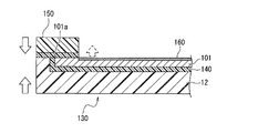
- FIG. 5 is an enlarged cross-sectional view of bipolar electrode 130 showing the effect of bipolar lead-acid battery 1 according to the embodiment.
- pillar 14 is abbreviate
- the positive electrode lead foil 101 is corroded by the sulfuric acid contained in the electrolyte, and a film 160 of corrosion products (lead oxide) is formed on the surface of the positive electrode lead foil 101. ing.
- the surface of the positive electrode lead foil 101 on which the coating 160 is formed is the creeping surface, and the growth of the coating 160 extends the creeping distance. Then, when the positive electrode lead foil 101 grows due to the growth of the film 160, as indicated by the direction of the dashed arrow in FIG. direction side).
- the cover plate 150 is provided so as to cover the peripheral edge portion 101c including the end portion 101a of the positive electrode lead foil 101.
- the positive electrode has been described as an example in the embodiments of the present invention.
- the cover plate should be provided at least on the positive electrode, but the structure described can also be employed on the negative electrode.
- Bipolar lead-acid battery 12 Substrate (bipolar plate) DESCRIPTION OF SYMBOLS 101... Positive electrode lead foil 101a... End part 101b... Opposing surface 101c... Peripheral part 101d... Peripheral part 102... Negative electrode lead foil 103... Positive electrode active material layer 104... Negative electrode active material layer 105 Electrolytic layer 110 Negative electrode 120 Positive electrode 130 Bipolar electrode 140 Adhesive 150 Cover plate 150a One end 160 Coating
Landscapes
- Chemical & Material Sciences (AREA)
- Chemical Kinetics & Catalysis (AREA)
- Electrochemistry (AREA)
- General Chemical & Material Sciences (AREA)
- Engineering & Computer Science (AREA)
- Materials Engineering (AREA)
- Manufacturing & Machinery (AREA)
- Secondary Cells (AREA)
Priority Applications (2)
| Application Number | Priority Date | Filing Date | Title |
|---|---|---|---|
| JP2022576994A JPWO2022158096A1 (https=) | 2021-01-22 | 2021-11-15 | |
| US18/356,578 US20230361312A1 (en) | 2021-01-22 | 2023-07-21 | Bipolar Storage Battery |
Applications Claiming Priority (2)
| Application Number | Priority Date | Filing Date | Title |
|---|---|---|---|
| JP2021008959 | 2021-01-22 | ||
| JP2021-008959 | 2021-01-22 |
Related Child Applications (1)
| Application Number | Title | Priority Date | Filing Date |
|---|---|---|---|
| US18/356,578 Continuation US20230361312A1 (en) | 2021-01-22 | 2023-07-21 | Bipolar Storage Battery |
Publications (1)
| Publication Number | Publication Date |
|---|---|
| WO2022158096A1 true WO2022158096A1 (ja) | 2022-07-28 |
Family
ID=82548675
Family Applications (1)
| Application Number | Title | Priority Date | Filing Date |
|---|---|---|---|
| PCT/JP2021/041932 Ceased WO2022158096A1 (ja) | 2021-01-22 | 2021-11-15 | バイポーラ型蓄電池 |
Country Status (3)
| Country | Link |
|---|---|
| US (1) | US20230361312A1 (https=) |
| JP (1) | JPWO2022158096A1 (https=) |
| WO (1) | WO2022158096A1 (https=) |
Cited By (1)
| Publication number | Priority date | Publication date | Assignee | Title |
|---|---|---|---|---|
| WO2024004764A1 (ja) * | 2022-06-27 | 2024-01-04 | 古河電池株式会社 | 双極型蓄電池 |
Citations (5)
| Publication number | Priority date | Publication date | Assignee | Title |
|---|---|---|---|---|
| GB585703A (en) * | 1944-07-19 | 1947-02-20 | Wilhelm Georg Schmidt | Improvements in electric accumulators |
| US4098967A (en) * | 1973-05-23 | 1978-07-04 | Gould Inc. | Electrochemical system using conductive plastic |
| JPH0757768A (ja) * | 1993-06-21 | 1995-03-03 | General Motors Corp <Gm> | 二極バッテリー、その組立て方法及びハウジング形成方法 |
| JP2014530450A (ja) * | 2011-09-09 | 2014-11-17 | イースト ペン マニュファクチャリング カンパニー インコーポレーテッドEast Penn Manufacturing Co.,Inc. | 二極式電池およびプレート |
| WO2020243093A1 (en) * | 2019-05-24 | 2020-12-03 | Advanced Battery Concepts, LLC | Battery assembly with integrated edge seal and methods of forming the seal |
Family Cites Families (3)
| Publication number | Priority date | Publication date | Assignee | Title |
|---|---|---|---|---|
| US516253A (en) * | 1894-03-13 | Secondary battery | ||
| EP2389698B1 (en) * | 2009-01-21 | 2017-10-04 | Advanced Battery Concepts, Llc | Bipolar battery assembly |
| US11050093B2 (en) * | 2018-06-25 | 2021-06-29 | Eskra Technical Products, Inc. | Bipolar lead acid battery cells with increased energy density |
-
2021
- 2021-11-15 WO PCT/JP2021/041932 patent/WO2022158096A1/ja not_active Ceased
- 2021-11-15 JP JP2022576994A patent/JPWO2022158096A1/ja active Pending
-
2023
- 2023-07-21 US US18/356,578 patent/US20230361312A1/en active Pending
Patent Citations (5)
| Publication number | Priority date | Publication date | Assignee | Title |
|---|---|---|---|---|
| GB585703A (en) * | 1944-07-19 | 1947-02-20 | Wilhelm Georg Schmidt | Improvements in electric accumulators |
| US4098967A (en) * | 1973-05-23 | 1978-07-04 | Gould Inc. | Electrochemical system using conductive plastic |
| JPH0757768A (ja) * | 1993-06-21 | 1995-03-03 | General Motors Corp <Gm> | 二極バッテリー、その組立て方法及びハウジング形成方法 |
| JP2014530450A (ja) * | 2011-09-09 | 2014-11-17 | イースト ペン マニュファクチャリング カンパニー インコーポレーテッドEast Penn Manufacturing Co.,Inc. | 二極式電池およびプレート |
| WO2020243093A1 (en) * | 2019-05-24 | 2020-12-03 | Advanced Battery Concepts, LLC | Battery assembly with integrated edge seal and methods of forming the seal |
Cited By (1)
| Publication number | Priority date | Publication date | Assignee | Title |
|---|---|---|---|---|
| WO2024004764A1 (ja) * | 2022-06-27 | 2024-01-04 | 古河電池株式会社 | 双極型蓄電池 |
Also Published As
| Publication number | Publication date |
|---|---|
| JPWO2022158096A1 (https=) | 2022-07-28 |
| US20230361312A1 (en) | 2023-11-09 |
Similar Documents
| Publication | Publication Date | Title |
|---|---|---|
| JP5363404B2 (ja) | 二次電池 | |
| JPH01132064A (ja) | 二次電池およびその製造方法 | |
| KR20120007508A (ko) | 갈바니 전지용 전극 스택 | |
| KR20090028243A (ko) | 전지용 파우치 및 파우치형 전지 | |
| KR101383804B1 (ko) | 적층 박막 전지 | |
| KR20110000517A (ko) | 코인형 2차 전지 | |
| WO2016121279A1 (ja) | 電池モジュール及び電池モジュールの解体方法 | |
| KR20180102927A (ko) | 배터리 셀 및 그 제조 방법 | |
| WO2022158096A1 (ja) | バイポーラ型蓄電池 | |
| US11145923B2 (en) | Battery structure | |
| KR20040021307A (ko) | 버튼형 및 코인형 전지 | |
| KR20170050445A (ko) | 파우치형 이차전지 | |
| EP3309857B1 (en) | Battery structure | |
| KR102231584B1 (ko) | 이차전지용 전극 조립체, 이의 제조 방법 및 이를 포함하는 리튬이차전지 | |
| KR20190091094A (ko) | 배터리 팩 및 그의 라벨 부착 방법 | |
| WO2022070829A1 (ja) | バイポーラ型蓄電池 | |
| KR102458417B1 (ko) | 포케팅 양극체의 제조방법, 포케팅 양극체 및 포케팅 양극체를 포함하는 전극조립체 | |
| KR20010008762A (ko) | 리튬폴리머 이차전지 | |
| US20230335710A1 (en) | Bipolar Electrode and Bipolar Storage Battery | |
| KR102205425B1 (ko) | 이차전지용 전극 조립체, 이의 제조 방법 및 이를 포함하는 리튬이차전지 | |
| WO2022201834A1 (ja) | バイポーラ型蓄電池及びバイポーラ型蓄電池の製造方法 | |
| KR20220119476A (ko) | 개선된 밀폐 수단을 포함하는 배터리형 전기화학적 장치 및 그 제조 방법 | |
| US20240021883A1 (en) | Bipolar Storage Battery | |
| KR100553735B1 (ko) | 이차전지 및 그 제조방법 | |
| US20240072353A1 (en) | Pouch-Type Secondary Battery With Excellent Insulation And Heat-Dissipating Properties |
Legal Events
| Date | Code | Title | Description |
|---|---|---|---|
| 121 | Ep: the epo has been informed by wipo that ep was designated in this application |
Ref document number: 21921199 Country of ref document: EP Kind code of ref document: A1 |
|
| ENP | Entry into the national phase |
Ref document number: 2022576994 Country of ref document: JP Kind code of ref document: A |
|
| NENP | Non-entry into the national phase |
Ref country code: DE |
|
| 122 | Ep: pct application non-entry in european phase |
Ref document number: 21921199 Country of ref document: EP Kind code of ref document: A1 |