WO2022157828A1 - 回転電機及びドア装置 - Google Patents
回転電機及びドア装置 Download PDFInfo
- Publication number
- WO2022157828A1 WO2022157828A1 PCT/JP2021/001672 JP2021001672W WO2022157828A1 WO 2022157828 A1 WO2022157828 A1 WO 2022157828A1 JP 2021001672 W JP2021001672 W JP 2021001672W WO 2022157828 A1 WO2022157828 A1 WO 2022157828A1
- Authority
- WO
- WIPO (PCT)
- Prior art keywords
- bearing
- shaft
- magnet
- load side
- face
- Prior art date
- Legal status (The legal status is an assumption and is not a legal conclusion. Google has not performed a legal analysis and makes no representation as to the accuracy of the status listed.)
- Ceased
Links
Images


Classifications
-
- H—ELECTRICITY
- H02—GENERATION; CONVERSION OR DISTRIBUTION OF ELECTRIC POWER
- H02K—DYNAMO-ELECTRIC MACHINES
- H02K11/00—Structural association of dynamo-electric machines with electric components or with devices for shielding, monitoring or protection
- H02K11/20—Structural association of dynamo-electric machines with electric components or with devices for shielding, monitoring or protection for measuring, monitoring, testing, protecting or switching
- H02K11/21—Devices for sensing speed or position, or actuated thereby
- H02K11/215—Magnetic effect devices, e.g. Hall-effect or magneto-resistive elements
Definitions
- the present disclosure relates to a rotating electric machine having a magnet provided at the end of a shaft and a magnetic sensor provided facing the magnet, and a door device including the same.
- Patent Document 1 describes a magnetic encoder that detects the rotation angle of a shaft.
- This magnetic encoder includes a shaft, a bearing that supports the inner end of the shaft opposite to the load, a magnet that is fixed to the inner end of the shaft, and a magnetic detector that faces the magnet. and an element.
- the axial end face of the bearing is flush with the end face of the inner end of the shaft.
- the magnet is fixed in a recess formed in the end face of the inner end of the shaft.
- Magnets used in magnetic encoders include radially magnetized magnets that are magnetized along the radial direction perpendicular to the axis of the shaft, and axial magnets that are magnetized along the axial direction parallel to the axis of the shaft. There is also a magnetized type.
- radially magnetized magnets When radially magnetized magnets are used in the magnetic encoder, the direction of the magnetic flux of the magnets is radial. A bearing made of a magnetic material is often arranged on the radially outer side of the magnet. For this reason, when radially magnetized magnets are used in the magnetic encoder, the magnetic flux of the magnets tends to leak to the bearings, reducing the magnetic flux passing through the magnetic detection element.
- the shaft is made of a magnetic material
- the magnetic flux of the magnet tends to leak to the shaft as well, so the magnetic flux passing through the magnetic detection element is further reduced. Therefore, when radially magnetized magnets are used in the magnetic encoder, there is a problem that the detection accuracy of the rotation angle is degraded.
- An object of the present invention is to provide a door device with
- a rotary electric machine includes a housing, a stator fixed to the housing, a rotor provided on the inner peripheral side of the stator, a shaft formed of a magnetic material and passing through the center of the rotor, the a first bearing provided between the housing and the shaft and positioned closer to the load side than the rotor in the axial direction along the axis of the shaft; a second bearing located on the anti-load side of the rotor with respect to the direction; a magnet provided at an end of the shaft on the anti-load side and magnetized along a direction perpendicular to the axial direction; and a magnetic sensor provided opposite to, wherein the shaft end surface that is the end surface of the shaft on the anti-load side is on the same plane as the bearing end surface that is the end surface of the second bearing on the anti-load side, Alternatively, the shaft end surface is located on the load side of the bearing end surface, a recess is formed in the shaft end surface, the magnet is fitted in the recess, and a part
- a door apparatus includes a door panel that opens and closes an entrance, a girder arranged above the door panel, and a rotating electric machine according to the present disclosure that is a door motor provided on the girder for moving the door panel. , provided.
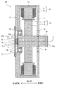
- FIG. 1 is a cross-sectional view showing a configuration of a rotating electric machine according to Embodiment 1;
- FIG. FIG. 7 is a cross-sectional view showing the configuration of a rotating electric machine according to Embodiment 2;
- FIG. 11 is a front view showing the configuration of a door device according to Embodiment 3;
- FIG. 1 is a cross-sectional view showing the configuration of a rotating electrical machine according to this embodiment.
- the direction along the axis 41 of the shaft 40 is defined as the axial direction
- the direction along the radius of the shaft 40 on a plane perpendicular to the axial direction is defined as the radial direction.
- the right side in FIG. 1 represents the load side of the rotary electric machine 100 in the axial direction.
- the left side in FIG. 1 represents the anti-load side of the rotary electric machine 100 in the axial direction.
- the rotating electrical machine 100 has a housing 10, a stator 20, a rotor 30, a shaft 40, a first bearing 50, a second bearing 60 and an angle detector 90.
- the housing 10 has a flat plate-like first shaft support portion 11 and a flat plate-like second shaft support portion 12 facing the first shaft support portion 11 .
- the second shaft support portion 12 is located on the anti-load side of the first shaft support portion 11 .
- the first shaft support portion 11 is provided with a circular first opening 11a.
- the second shaft support portion 12 is provided with a circular second opening 12a.
- Both the first bearing 50 and the second bearing 60 are located between the housing 10 and the shaft 40 .
- the first bearing 50 is mounted in the first opening 11 a of the housing 10 .
- the second bearing 60 is mounted in the second opening 12a of the housing 10.
- the shaft 40 is rotatably supported by the housing 10 via a first bearing 50 and a second bearing 60 .
- Both the first bearing 50 and the second bearing 60 are made of a magnetic material.
- the stator 20 is fixed to the housing 10.
- the stator 20 has an annular stator core 21 and stator coils 22 provided on the stator core 21 .
- the rotor 30 is provided on the inner peripheral side of the stator 20 .
- the rotor 30 has a rotor core 31 and a plurality of rotor magnets 32 fixed to the outer circumference of the rotor core 31 .
- the outer peripheral surface of rotor 30 faces the inner peripheral surface of stator 20 with a gap therebetween.
- a shaft 40 passes through the center of the rotor 30 .
- the rotor 30 rotates integrally with the shaft 40 around the axis 41 of the shaft 40 .
- the rotor 30 is arranged between the first bearing 50 and the second bearing 60 in the axial direction.
- the first bearing 50 is located on the load side of the rotor 30 in the axial direction.
- the second bearing 60 is located on the anti-load side of the rotor 30 in the axial direction.
- the shaft 40 is made of a magnetic material such as S45C.
- the shaft 40 has a first end 40a, which is the end on the load side, and a second end 40b, which is the end on the anti-load side.
- the first end portion 40 a protrudes outside the housing 10 through the first bearing 50 .
- the second end 40b is supported by the second bearing 60 within the second opening 12a.
- a second end portion 40b of the shaft 40 is provided with a shaft end surface 40c formed in a plane perpendicular to the axial direction.
- the second bearing 60 is provided with a planar bearing end surface 60a perpendicular to the axial direction as an end surface on the side opposite to the load.
- the shaft end face 40c is flush with the bearing end face 60a. That is, the shaft end face 40c is located on the same plane as the bearing end face 60a. However, the shaft end face 40c may be positioned closer to the load side than the bearing end face 60a.
- a recess 42 is formed in the center of the shaft end face 40c.
- the concave portion 42 has a cylindrical side wall surface 42a centered on the axis 41 and a flat bottom surface 42b perpendicular to the axial direction.
- the bottom surface 42b is positioned closer to the load than the shaft end surface 40c.
- the recess 42 has a circular shape centered on the axis 41 .
- the angle detector 90 is configured to output a signal corresponding to the rotation angle of the shaft 40.
- a signal output from the angle detector 90 is input to a control unit (not shown) of the rotating electric machine 100 .
- the angle detector 90 includes a magnet 70 provided at the second end 40b of the shaft 40, a magnetic sensor 80 provided facing the magnet 70, a sensor substrate 81 on which the magnetic sensor 80 is mounted, have.
- the magnet 70 is housed in a magnet case 71.
- the magnet case 71 is made of a non-magnetic material.
- the magnet case 71 has a cylindrical portion 71a and a bottom portion 71b closing one axial end of the cylindrical portion 71a.
- the other axial end of the cylindrical portion 71a is open.
- a bottom portion 71 b of the magnet case 71 is in contact with the bottom surface 42 b of the recess 42 .
- the cylindrical portion 71 a of the magnet case 71 is arranged along the side wall surface 42 a of the recess 42 .
- the magnet case 71 is fitted in the recess 42 so as to be coaxial with the shaft 40 and the other axial end of the cylindrical portion 71a faces the anti-load side.
- the entire magnet case 71 is accommodated within the recess 42 .
- An end surface 71c formed on the other axial end side of the cylindrical portion 71a is flush with the shaft end surface 40c.
- the end face 71c may protrude further toward the anti-load side than the shaft end face 40c.
- the end face 71c may protrude from the bearing end face 60a of the second bearing 60 toward the anti-load side.
- the magnet 70 is of a radial magnetization type magnetized along one direction perpendicular to the axial direction.
- the magnet 70 has a disk-like shape.
- the magnet 70 is fitted in the recess 42 via the magnet case 71 so as to be coaxial with the shaft 40 .
- a part of the magnet 70 protrudes from the magnet case 71 and the recess 42 to the anti-load side.
- a magnet end face 70a formed on the anti-load side of the magnet 70 is positioned further on the anti-load side than the shaft end face 40c in the axial direction.
- the magnet end face 70a is located on the anti-load side of the bearing end face 60a of the second bearing 60 in the axial direction. That is, a part of the magnet 70 protrudes toward the anti-load side from both the shaft end surface 40c and the bearing end surface 60a in the axial direction.
- the magnet case 71 may be omitted and the magnets 70 may be fitted directly into the recesses 42 . Even in this case, the magnet 70 is provided so that a portion of the magnet 70 protrudes toward the anti-load side from both the shaft end surface 40c and the bearing end surface 60a.
- the magnetic sensor 80 is provided facing the magnet end surface 70a of the magnet 70 with a gap therebetween.
- the magnetic sensor 80 detects the rotation angle of the shaft 40 according to the direction and intensity of magnetic flux from the magnet 70 .
- a magnetoresistive element or a Hall element is used as the magnetic sensor 80 .
- the sensor board 81 is a printed board on which the magnetic sensor 80 is mounted.
- the sensor board 81 is fixed to the second shaft support portion 12 of the housing 10 with a plurality of bolts.
- the second opening 12 a formed in the second shaft support portion 12 is closed by the sensor substrate 81 .
- the inner diameter of the first bearing 50 is R1
- the inner diameter of the second bearing 60 is R2.
- rotating electric machine 100 includes housing 10, stator 20, rotor 30, shaft 40, first bearing 50, second bearing 60, magnet 70, magnetic a formula sensor 80; Stator 20 is fixed to housing 10 .
- the rotor 30 is provided on the inner peripheral side of the stator 20 .
- the shaft 40 is made of a magnetic material and passes through the center of the rotor 30 .
- a first bearing 50 is provided between the housing 10 and the shaft 40 .
- the first bearing 50 is located on the load side of the rotor 30 in the axial direction along the axis 41 of the shaft 40 .
- a second bearing 60 is provided between the housing 10 and the shaft 40 .
- the second bearing 60 is located on the anti-load side of the rotor 30 in the axial direction.
- the magnet 70 is provided at the second end 40b, which is the end of the shaft 40 on the opposite load side.
- the magnet 70 is magnetized along a direction perpendicular to the axial direction.
- the magnetic sensor 80 is provided facing the magnet 70 .
- the shaft end face 40c which is the end face of the shaft 40 on the anti-load side, is on the same plane as the bearing end face 60a, which is the end face of the second bearing 60 on the anti-load side, or is located on the load side of the bearing end face 60a.
- a recess 42 is formed in the shaft end face 40c.
- a magnet 70 is fitted in the recess 42 . A part of the magnet 70 protrudes toward the anti-load side from the bearing end face 60a in the axial direction.
- the inner diameter R1 of the first bearing 50 and the inner diameter R2 of the second bearing 60 satisfy the relationship of R1 ⁇ R2.
- a part of the magnet 70 protrudes from both the bearing end surface 60a and the shaft end surface 40c toward the anti-load side. magnetic flux is less likely to leak to the second bearing 60 . As a result, reduction in the magnetic flux passing through the magnetic sensor 80 can be suppressed. Therefore, according to the present embodiment, even when the magnets 70 that are magnetized in the radial direction are used, it is possible to suppress a decrease in the detection accuracy of the rotation angle.
- the angle detector 90 can be thinned in the axial direction. Therefore, according to the present embodiment, the axial dimension of rotating electric machine 100 can be reduced.
- the inner diameter R2 of the second bearing 60 is smaller than the inner diameter R1 of the first bearing 50, the axial diameter of the second end 40b of the shaft 40 is smaller than the axial diameter of the first end 40a.
- the distance between the magnet 70 and the second bearing 60 tends to be shortened, making it difficult to prevent the magnetic flux of the magnet 70 from leaking to the second bearing 60 .
- the inner diameter R1 and the inner diameter R2 satisfy the relationship of R1 ⁇ R2, a long distance can be secured between the magnet 70 and the second bearing 60 . Therefore, according to the present embodiment, even when radially magnetized magnets 70 are used, the magnetic flux of magnets 70 can be prevented from leaking to second bearing 60 .
- the rotary electric machine 100 further includes a magnet case 71 that houses the magnets 70 .
- the magnet case 71 is made of a non-magnetic material.
- the magnet 70 is fitted in the recess 42 via the magnet case 71 . According to this configuration, the magnetic flux of the magnet 70 is less likely to leak to the shaft 40, so that the reduction of the magnetic flux passing through the magnetic sensor 80 can be further suppressed.
- FIG. 2 is a cross-sectional view showing the configuration of the rotating electric machine according to the present embodiment.
- the inner diameter R2 of the second bearing 60 is larger than the inner diameter R1 of the first bearing 50, unlike the first embodiment. That is, the inner diameter R1 and the inner diameter R2 satisfy the relationship of R1 ⁇ R2. Accordingly, the shaft diameter of the second end portion 40b of the shaft 40 is larger than the shaft diameter of the first end portion 40a.
- the axial diameter of the second end portion 40b of the shaft 40 is made larger than the axial diameter of the first end portion 40a. be able to.
- a longer distance can be secured between the magnet 70 and the second bearing 60, so that the magnetic flux of the magnet 70 leaks to the second bearing 60 even when the radially magnetized magnet 70 is used. can be suppressed. Therefore, according to the present embodiment, in addition to obtaining the same effects as those of the first embodiment, it is possible to further suppress deterioration in the detection accuracy of the rotation angle.
- FIG. 3 is a front view showing the configuration of the door device according to this embodiment.
- a door device used in an elevator car is illustrated.
- a car doorway 121a is provided on the front surface of the car 121.
- the car doorway 121a is opened and closed by a first car door 122a and a second car door 122b.
- Each of the first car door 122 a and the second car door 122 b has a door panel 123 and a door hanger 124 fixed to the top of the door panel 123 .
- Each door hanger 124 is provided with a plurality of hanger rollers 125 .
- a girder 127 is fixed to the top of the front surface of the car 121 .
- a hanger rail 128 is provided on the girder 127 .
- the first car door 122a and the second car door 122b are suspended from hanger rails 128 and move along the hanger rails 128 when opening and closing the car doorway 121a.
- the hanger rollers 125 move while rolling on the hanger rails 128 when the first car door 122a and the second car door 122b are opened and closed.
- the rotary electric machine 100 of Embodiment 1 or 2 is fixed as a door motor to one end of the beam 127 in the width direction of the car doorway 121a.
- a first pulley 130 is fixed to the first end portion 40 a of the shaft 40 of the rotating electric machine 100 .
- a second pulley 131 is rotatably provided at the other end of the girder 127 in the width direction of the car doorway 121a.
- An endless belt 132 is wound around the first pulley 130 and the second pulley 131 .
- the first car door 122a is connected to the upper portion of the belt 132 via the first connecting member 133a.
- the second car door 122b is connected to the lower portion of the belt 132 via a second connecting member 133b.
- Rotating the first pulley 130 by the electric rotating machine 100 causes the first car door 122 a and the second car door 122 b to open and close along the hanger rails 128 .
- the door device includes the door panel 123, the girder 127, and the rotating electric machine 100 of the first or second embodiment.
- the door panel 123 is configured to open and close the car doorway 121a.
- the girder 127 is arranged above the door panel 123 .
- the rotating electric machine 100 is a door motor that moves the door panel 123 . According to this configuration, the same effects as in the first or second embodiment can be obtained in the door device.
- rotating electrical machine 100 of Embodiments 1 and 2 can also be applied to motors other than elevator door motors, generators, and generator motors.
Landscapes
- Engineering & Computer Science (AREA)
- Microelectronics & Electronic Packaging (AREA)
- Power Engineering (AREA)
- Motor Or Generator Frames (AREA)
Abstract
回転電機は、ハウジングと、ステータと、ロータと、磁性体により形成されたシャフトと、ロータよりも負荷側に位置する第1軸受と、ロータよりも反負荷側に位置する第2軸受と、反負荷側におけるシャフトの端部に設けられ、軸方向と垂直な方向に沿って着磁された磁石と、磁石と対向して設けられた磁気式センサと、を備え、シャフトのシャフト端面は、第2軸受の軸受端面と同一平面上、又は軸受端面よりも負荷側に位置しており、シャフト端面には、凹部が形成されており、磁石は、凹部に嵌め込まれており、磁石の一部は、軸方向において軸受端面よりも反負荷側に突出しており、第1軸受の内径R1及び第2軸受の内径R2は、R1≦R2の関係を満たしている。
Description
本開示は、シャフトの端部に設けられた磁石と磁石に対向して設けられた磁気式センサとを有する回転電機、及びそれを備えたドア装置に関する。
特許文献1には、シャフトの回転角度を検出する磁気式エンコーダが記載されている。この磁気式エンコーダは、シャフトと、シャフトの反負荷側の端部である内端部を支持する軸受と、シャフトの内端部に固定された磁石と、磁石と対向して配置された磁気検出素子と、を有している。軸受の軸方向端面は、シャフトの内端部の端面と面一になっている。磁石は、シャフトの内端部の端面に形成された凹部内に固定されている。
磁気式エンコーダに用いられる磁石には、シャフトの軸心と垂直な径方向に沿って着磁された径方向着磁型、シャフトの軸心と平行な軸方向に沿って着磁された軸方向着磁型などがある。磁気式エンコーダに径方向着磁型の磁石が用いられる場合、磁石の磁束の向きは径方向になる。磁石の径方向外側には、磁性体により形成される軸受が配置されることが多い。このため、磁気式エンコーダに径方向着磁型の磁石が用いられる場合、磁石の磁束が軸受に漏れやすくなり、磁気検出素子を通る磁束が減少する。特に、シャフトが磁性体により形成されている場合には、磁石の磁束がシャフトにも漏れやすくなるため、磁気検出素子を通る磁束がさらに減少する。したがって、磁気式エンコーダに径方向着磁型の磁石が用いられる場合、回転角度の検出精度が低下してしまうという課題があった。
本開示は、上述のような課題を解決するためになされたものであり、径方向着磁型の磁石が用いられる場合であっても、回転角度の検出精度の低下を抑制できる回転電機及びそれを備えたドア装置を提供することを目的とする。
本開示に係る回転電機は、ハウジングと、前記ハウジングに固定されたステータと、前記ステータの内周側に設けられたロータと、磁性体により形成され、前記ロータの中心を貫通したシャフトと、前記ハウジングと前記シャフトとの間に設けられ、前記シャフトの軸心に沿った軸方向において前記ロータよりも負荷側に位置する第1軸受と、前記ハウジングと前記シャフトとの間に設けられ、前記軸方向において前記ロータよりも反負荷側に位置する第2軸受と、前記反負荷側における前記シャフトの端部に設けられ、前記軸方向と垂直な方向に沿って着磁された磁石と、前記磁石と対向して設けられた磁気式センサと、を備え、前記反負荷側における前記シャフトの端面であるシャフト端面は、前記反負荷側における前記第2軸受の端面である軸受端面と同一平面上、又は前記軸受端面よりも前記負荷側に位置しており、前記シャフト端面には、凹部が形成されており、前記磁石は、前記凹部に嵌め込まれており、前記磁石の一部は、前記軸方向において前記軸受端面よりも前記反負荷側に突出しており、前記第1軸受の内径R1及び前記第2軸受の内径R2は、R1≦R2の関係を満たしている。
本開示に係るドア装置は、出入口を開閉するドアパネルと、前記ドアパネルの上方に配置されている桁と、前記桁に設けられており、前記ドアパネルを移動させるドアモータである本開示に係る回転電機と、を備える。
本開示に係るドア装置は、出入口を開閉するドアパネルと、前記ドアパネルの上方に配置されている桁と、前記桁に設けられており、前記ドアパネルを移動させるドアモータである本開示に係る回転電機と、を備える。
本開示によれば、径方向着磁型の磁石が用いられる場合であっても、回転角度の検出精度の低下を抑制することができる。
実施の形態1.
実施の形態1に係る回転電機について説明する。図1は、本実施の形態に係る回転電機の構成を示す断面図である。図1において、シャフト40の軸心41に沿った方向を軸方向とし、軸方向と垂直な平面においてシャフト40の半径に沿った方向を径方向とする。図1中の右側は、軸方向における回転電機100の負荷側を表している。図1中の左側は、軸方向における回転電機100の反負荷側を表している。
実施の形態1に係る回転電機について説明する。図1は、本実施の形態に係る回転電機の構成を示す断面図である。図1において、シャフト40の軸心41に沿った方向を軸方向とし、軸方向と垂直な平面においてシャフト40の半径に沿った方向を径方向とする。図1中の右側は、軸方向における回転電機100の負荷側を表している。図1中の左側は、軸方向における回転電機100の反負荷側を表している。
図1に示すように、回転電機100は、ハウジング10、ステータ20、ロータ30、シャフト40、第1軸受50、第2軸受60及び角度検出器90を有している。
ハウジング10は、平板状の第1軸支持部11と、第1軸支持部11に対向する平板状の第2軸支持部12と、を有している。第2軸支持部12は、第1軸支持部11よりも反負荷側に位置している。第1軸支持部11には、円形の第1開口11aが設けられている。第2軸支持部12には、円形の第2開口12aが設けられている。
第1軸受50及び第2軸受60はいずれも、ハウジング10とシャフト40との間に位置している。第1軸受50は、ハウジング10の第1開口11aに装着されている。第2軸受60は、ハウジング10の第2開口12aに装着されている。シャフト40は、第1軸受50及び第2軸受60を介して、ハウジング10に回転自在に支持されている。第1軸受50及び第2軸受60はいずれも、磁性体により形成されている。
ステータ20は、ハウジング10に固定されている。ステータ20は、環状のステータコア21と、ステータコア21に設けられたステータコイル22と、を有している。
ロータ30は、ステータ20の内周側に設けられている。ロータ30は、ロータコア31と、ロータコア31の外周部にそれぞれ固定された複数のロータ磁石32と、を有している。ロータ30の外周面は、隙間を介してステータ20の内周面と対向している。ロータ30の中心部には、シャフト40が貫通している。ロータ30は、シャフト40の軸心41を中心として、シャフト40と一体に回転する。
ロータ30は、軸方向において第1軸受50と第2軸受60との間に配置されている。第1軸受50は、軸方向においてロータ30よりも負荷側に位置している。第2軸受60は、軸方向においてロータ30よりも反負荷側に位置している。
シャフト40は、S45C等の磁性体により形成されている。シャフト40は、負荷側の端部である第1端部40aと、反負荷側の端部である第2端部40bと、を有している。第1端部40aは、第1軸受50を貫通してハウジング10の外部に突出している。第2端部40bは、第2開口12a内で第2軸受60に支持されている。
シャフト40の第2端部40bには、軸方向と垂直な平面状に形成されたシャフト端面40cが設けられている。第2軸受60には、反負荷側の端面として、軸方向と垂直な平面状に形成された軸受端面60aが設けられている。シャフト端面40cは、軸受端面60aと面一になっている。すなわち、シャフト端面40cは、軸受端面60aと同一平面上に位置している。ただし、シャフト端面40cは、軸受端面60aよりも負荷側に位置していてもよい。
シャフト端面40cの中心部には、凹部42が形成されている。凹部42は、軸心41を中心とした円筒面状の側壁面42aと、軸方向と垂直な平面状に形成された底面42bと、を有している。底面42bは、シャフト端面40cよりも負荷側に位置している。軸方向に沿って見ると、凹部42は、軸心41を中心とした円形の形状を有している。
角度検出器90は、シャフト40の回転角度に応じた信号を出力するように構成されている。角度検出器90から出力された信号は、回転電機100の不図示の制御部に入力される。角度検出器90は、シャフト40の第2端部40bに設けられた磁石70と、磁石70と対向して設けられた磁気式センサ80と、磁気式センサ80が実装されたセンサ基板81と、を有している。
磁石70は、磁石ケース71に収容されている。磁石ケース71は、非磁性材料により形成されている。磁石ケース71は、円筒部71aと、円筒部71aの軸方向一端を塞ぐ底部71bと、を有している。円筒部71aの軸方向他端は開口されている。磁石ケース71の底部71bは、凹部42の底面42bと接触している。磁石ケース71の円筒部71aは、凹部42の側壁面42aに沿って配置されている。磁石ケース71は、シャフト40と同軸になりかつ円筒部71aの軸方向他端が反負荷側を向くように、凹部42に嵌め込まれている。磁石ケース71の全体は、凹部42内に収容されている。円筒部71aの軸方向他端側に形成された端面71cは、シャフト端面40cと面一になっている。ただし、端面71cは、シャフト端面40cよりも反負荷側に突出していてもよい。また、端面71cは、第2軸受60の軸受端面60aよりも反負荷側に突出していてもよい。
磁石70は、軸方向と垂直な一方向に沿って着磁された径方向着磁型である。磁石70は、円板状の形状を有している。磁石70は、シャフト40と同軸になるように、磁石ケース71を介して凹部42に嵌め込まれている。
磁石70の一部は、磁石ケース71及び凹部42から反負荷側にはみ出している。磁石70の反負荷側に形成された磁石端面70aは、軸方向において、シャフト端面40cよりも反負荷側に位置している。また、磁石端面70aは、軸方向において、第2軸受60の軸受端面60aよりも反負荷側に位置している。つまり、磁石70の一部は、軸方向において、シャフト端面40c及び軸受端面60aのいずれよりも反負荷側に突出している。
ここで、磁石ケース71を省略し、磁石70が直接凹部42に嵌め込まれるようにしてもよい。この場合であっても、磁石70は、当該磁石70の一部がシャフト端面40c及び軸受端面60aのいずれよりも反負荷側に突出するように設けられる。
磁気式センサ80は、隙間を介して磁石70の磁石端面70aと対向して設けられている。磁気式センサ80は、磁石70からの磁束の方向及び磁束の強さに応じて、シャフト40の回転角度を検出する。磁気式センサ80としては、磁気抵抗素子又はホール素子が用いられている。
センサ基板81は、磁気式センサ80が実装されたプリント基板である。センサ基板81は、複数のボルトによりハウジング10の第2軸支持部12に固定されている。第2軸支持部12に形成された第2開口12aは、センサ基板81によって塞がれている。
ここで、第1軸受50の内径をR1とし、第2軸受60の内径をR2とする。このとき、内径R1及び内径R2は、R1=R2の関係を満たしている。
以上説明したように、本実施の形態に係る回転電機100は、ハウジング10と、ステータ20と、ロータ30と、シャフト40と、第1軸受50と、第2軸受60と、磁石70と、磁気式センサ80と、を備えている。ステータ20は、ハウジング10に固定されている。ロータ30は、ステータ20の内周側に設けられている。シャフト40は、磁性体により形成されており、ロータ30の中心を貫通している。第1軸受50は、ハウジング10とシャフト40との間に設けられている。第1軸受50は、シャフト40の軸心41に沿った軸方向においてロータ30よりも負荷側に位置している。第2軸受60は、ハウジング10とシャフト40との間に設けられている。第2軸受60は、軸方向においてロータ30よりも反負荷側に位置している。磁石70は、反負荷側におけるシャフト40の端部である第2端部40bに設けられている。磁石70は、軸方向と垂直な方向に沿って着磁されている。磁気式センサ80は、磁石70と対向して設けられている。
反負荷側におけるシャフト40の端面であるシャフト端面40cは、反負荷側における第2軸受60の端面である軸受端面60aと同一平面上、又は軸受端面60aよりも負荷側に位置している。シャフト端面40cには、凹部42が形成されている。磁石70は、凹部42に嵌め込まれている。磁石70の一部は、軸方向において軸受端面60aよりも反負荷側に突出している。第1軸受50の内径R1及び第2軸受60の内径R2は、R1≦R2の関係を満たしている。
この構成によれば、磁石70の一部が軸受端面60a及びシャフト端面40cのいずれよりも反負荷側に突出するため、径方向着磁型の磁石70が用いられる場合であっても、磁石70の磁束が第2軸受60に漏れにくくなる。これにより、磁気式センサ80を通る磁束の減少を抑制できる。したがって、本実施の形態によれば、径方向着磁型の磁石70が用いられる場合であっても、回転角度の検出精度の低下を抑制することができる。
また、上記構成によれば、シャフト端面40cに形成された凹部42に磁石70が嵌め込まれているため、角度検出器90を軸方向に薄型化することができる。したがって、本実施の形態によれば、回転電機100の軸方向寸法を小さくすることができる。
第2軸受60の内径R2が第1軸受50の内径R1よりも小さい場合、シャフト40の第2端部40bの軸径が第1端部40aの軸径よりも小さくなる。これにより、磁石70と第2軸受60との間の距離が短くなりやすいため、磁石70の磁束が第2軸受60に漏れるのを抑えることが困難である。これに対し、上記構成では、内径R1及び内径R2がR1≦R2の関係を満たしているため、磁石70と第2軸受60との間の距離を長く確保することができる。したがって、本実施の形態によれば、径方向着磁型の磁石70が用いられる場合であっても、磁石70の磁束が第2軸受60に漏れるのを抑えることができる。
本実施の形態に係る回転電機100において、内径R1及び内径R2は、R1=R2の関係を満たしている。この構成によれば、第1軸受50及び第2軸受60を同サイズにすることができるため、第1軸受50及び第2軸受60を共通部品化することができる。したがって、本実施の形態によれば、回転電機100の部品の種類を削減することができ、回転電機100の部品コストを低減することができる。
本実施の形態に係る回転電機100は、磁石70を収容する磁石ケース71をさらに備えている。磁石ケース71は、非磁性材料により形成されている。磁石70は、磁石ケース71を介して凹部42に嵌め込まれている。この構成によれば、磁石70の磁束がシャフト40に漏れにくくなるため、磁気式センサ80を通る磁束の減少をさらに抑制することができる。
実施の形態2.
実施の形態2に係る回転電機について説明する。図2は、本実施の形態に係る回転電機の構成を示す断面図である。図2に示すように、本実施の形態では、実施の形態1と異なり、第2軸受60の内径R2が第1軸受50の内径R1よりも大きくなっている。すなわち、内径R1及び内径R2は、R1<R2の関係を満たしている。これに伴い、シャフト40の第2端部40bの軸径は、第1端部40aの軸径よりも大きくなっている。
実施の形態2に係る回転電機について説明する。図2は、本実施の形態に係る回転電機の構成を示す断面図である。図2に示すように、本実施の形態では、実施の形態1と異なり、第2軸受60の内径R2が第1軸受50の内径R1よりも大きくなっている。すなわち、内径R1及び内径R2は、R1<R2の関係を満たしている。これに伴い、シャフト40の第2端部40bの軸径は、第1端部40aの軸径よりも大きくなっている。
本実施の形態では、第2軸受60の内径R2が第1軸受50の内径R1よりも大きいため、シャフト40の第2端部40bの軸径を第1端部40aの軸径よりも大きくすることができる。これにより、磁石70と第2軸受60との間の距離をより長く確保できるため、径方向着磁型の磁石70が用いられる場合であっても、磁石70の磁束が第2軸受60に漏れるのを抑えることができる。したがって、本実施の形態によれば、実施の形態1と同様の効果が得られることに加えて、回転角度の検出精度の低下をさらに抑制することができる。
実施の形態3.
実施の形態3に係るドア装置について説明する。図3は、本実施の形態に係るドア装置の構成を示す正面図である。本実施の形態では、エレベータのかごに用いられるドア装置を例示している。
実施の形態3に係るドア装置について説明する。図3は、本実施の形態に係るドア装置の構成を示す正面図である。本実施の形態では、エレベータのかごに用いられるドア装置を例示している。
図3に示すように、かご121の前面には、かご出入口121aが設けられている。かご出入口121aは、第1かごドア122a及び第2かごドア122bにより開閉される。第1かごドア122a及び第2かごドア122bのそれぞれは、ドアパネル123と、ドアパネル123の上部に固定されているドアハンガ124と、を有している。各ドアハンガ124には、複数のハンガローラ125が設けられている。
かご121の前面の上部には、桁127が固定されている。桁127には、ハンガレール128が設けられている。第1かごドア122a及び第2かごドア122bは、ハンガレール128から吊り下げられており、かご出入口121aの開閉時にハンガレール128に沿って移動する。また、ハンガローラ125は、第1かごドア122a及び第2かごドア122bの開閉動作時にハンガレール128上を転がりながら移動する。
かご出入口121aの幅方向の桁127の一端部には、ドアモータとして、実施の形態1又は2の回転電機100が固定されている。回転電機100のシャフト40の第1端部40aには、第1プーリ130が固定されている。
かご出入口121aの幅方向の桁127の他端部には、第2プーリ131が回転可能に設けられている。第1プーリ130と第2プーリ131には、無端状のベルト132が巻かれている。
第1かごドア122aは、第1接続部材133aを介してベルト132の上側部分に接続されている。第2かごドア122bは、第2接続部材133bを介してベルト132の下側部分に接続されている。回転電機100により第1プーリ130を回転させることにより、第1かごドア122a及び第2かごドア122bがハンガレール128に沿って開閉動作する。
以上説明したように、本実施の形態に係るドア装置は、ドアパネル123と、桁127と、実施の形態1又は2の回転電機100と、を備えている。ドアパネル123は、かご出入口121aを開閉するように構成されている。桁127は、ドアパネル123の上方に配置されている。回転電機100は、ドアパネル123を移動させるドアモータである。この構成によれば、ドア装置において実施の形態1又は2と同様の効果を得ることができる。
なお、上記実施の形態1及び2の回転電機100は、エレベータのドアモータ以外の電動機、発電機及び発電電動機にも適用できる。
10 ハウジング、11 第1軸支持部、11a 第1開口、12 第2軸支持部、12a 第2開口、20 ステータ、21 ステータコア、22 ステータコイル、30 ロータ、31 ロータコア、32 ロータ磁石、40 シャフト、40a 第1端部、40b 第2端部、40c シャフト端面、41 軸心、42 凹部、42a 側壁面、42b 底面、50 第1軸受、60 第2軸受、60a 軸受端面、70 磁石、70a 磁石端面、71 磁石ケース、71a 円筒部、71b 底部、71c 端面、80 磁気式センサ、81 センサ基板、90 角度検出器、100 回転電機、121 かご、121a かご出入口、122a 第1かごドア、122b 第2かごドア、123 ドアパネル、124 ドアハンガ、125 ハンガローラ、127 桁、128 ハンガレール、130 第1プーリ、131 第2プーリ、132 ベルト、133a 第1接続部材、133b 第2接続部材。
Claims (5)
- ハウジングと、
前記ハウジングに固定されたステータと、
前記ステータの内周側に設けられたロータと、
磁性体により形成され、前記ロータの中心を貫通したシャフトと、
前記ハウジングと前記シャフトとの間に設けられ、前記シャフトの軸心に沿った軸方向において前記ロータよりも負荷側に位置する第1軸受と、
前記ハウジングと前記シャフトとの間に設けられ、前記軸方向において前記ロータよりも反負荷側に位置する第2軸受と、
前記反負荷側における前記シャフトの端部に設けられ、前記軸方向と垂直な方向に沿って着磁された磁石と、
前記磁石と対向して設けられた磁気式センサと、
を備え、
前記反負荷側における前記シャフトの端面であるシャフト端面は、前記反負荷側における前記第2軸受の端面である軸受端面と同一平面上、又は前記軸受端面よりも前記負荷側に位置しており、
前記シャフト端面には、凹部が形成されており、
前記磁石は、前記凹部に嵌め込まれており、
前記磁石の一部は、前記軸方向において前記軸受端面よりも前記反負荷側に突出しており、
前記第1軸受の内径R1及び前記第2軸受の内径R2は、R1≦R2の関係を満たしている回転電機。 - 前記内径R1及び前記内径R2は、R1=R2の関係を満たしている請求項1に記載の回転電機。
- 前記内径R1及び前記内径R2は、R1<R2の関係を満たしている請求項1に記載の回転電機。
- 非磁性材料により形成され、前記磁石を収容する磁石ケースをさらに備え、
前記磁石は、前記磁石ケースを介して前記凹部に嵌め込まれている請求項1~請求項3のいずれか一項に記載の回転電機。 - 出入口を開閉するドアパネルと、
前記ドアパネルの上方に配置されている桁と、
前記桁に設けられており、前記ドアパネルを移動させるドアモータである請求項1~請求項4のいずれか一項に記載の回転電機と、
を備えるドア装置。
Priority Applications (2)
| Application Number | Priority Date | Filing Date | Title |
|---|---|---|---|
| JP2021570452A JPWO2022157828A1 (ja) | 2021-01-19 | 2021-01-19 | |
| PCT/JP2021/001672 WO2022157828A1 (ja) | 2021-01-19 | 2021-01-19 | 回転電機及びドア装置 |
Applications Claiming Priority (1)
| Application Number | Priority Date | Filing Date | Title |
|---|---|---|---|
| PCT/JP2021/001672 WO2022157828A1 (ja) | 2021-01-19 | 2021-01-19 | 回転電機及びドア装置 |
Publications (1)
| Publication Number | Publication Date |
|---|---|
| WO2022157828A1 true WO2022157828A1 (ja) | 2022-07-28 |
Family
ID=82549598
Family Applications (1)
| Application Number | Title | Priority Date | Filing Date |
|---|---|---|---|
| PCT/JP2021/001672 Ceased WO2022157828A1 (ja) | 2021-01-19 | 2021-01-19 | 回転電機及びドア装置 |
Country Status (2)
| Country | Link |
|---|---|
| JP (1) | JPWO2022157828A1 (ja) |
| WO (1) | WO2022157828A1 (ja) |
Citations (7)
| Publication number | Priority date | Publication date | Assignee | Title |
|---|---|---|---|---|
| JPH06296382A (ja) * | 1993-04-06 | 1994-10-21 | Mitsubishi Electric Corp | 回転ブレーキ付モータ |
| JP2003324930A (ja) * | 2002-04-26 | 2003-11-14 | Asahi Kasei Corp | 非接触型回転角度検出装置 |
| JP2006233985A (ja) * | 2005-02-22 | 2006-09-07 | Ntn Corp | 回転検出装置付き軸受 |
| JP2010190846A (ja) * | 2009-02-20 | 2010-09-02 | Koyo Electronics Ind Co Ltd | 磁気式エンコーダ |
| JP2016119806A (ja) * | 2014-12-22 | 2016-06-30 | 日本精工株式会社 | センサマグネット固定構造及びその固定構造を備えたモータ並びにそれを搭載した電動パワーステアリング装置及び車両 |
| WO2019012694A1 (ja) * | 2017-07-14 | 2019-01-17 | 三菱電機株式会社 | 回転電機及びそれを用いたドア装置 |
| JP2020162399A (ja) * | 2019-03-28 | 2020-10-01 | キヤノンプレシジョン株式会社 | ブラシレスモータ |
-
2021
- 2021-01-19 JP JP2021570452A patent/JPWO2022157828A1/ja active Pending
- 2021-01-19 WO PCT/JP2021/001672 patent/WO2022157828A1/ja not_active Ceased
Patent Citations (7)
| Publication number | Priority date | Publication date | Assignee | Title |
|---|---|---|---|---|
| JPH06296382A (ja) * | 1993-04-06 | 1994-10-21 | Mitsubishi Electric Corp | 回転ブレーキ付モータ |
| JP2003324930A (ja) * | 2002-04-26 | 2003-11-14 | Asahi Kasei Corp | 非接触型回転角度検出装置 |
| JP2006233985A (ja) * | 2005-02-22 | 2006-09-07 | Ntn Corp | 回転検出装置付き軸受 |
| JP2010190846A (ja) * | 2009-02-20 | 2010-09-02 | Koyo Electronics Ind Co Ltd | 磁気式エンコーダ |
| JP2016119806A (ja) * | 2014-12-22 | 2016-06-30 | 日本精工株式会社 | センサマグネット固定構造及びその固定構造を備えたモータ並びにそれを搭載した電動パワーステアリング装置及び車両 |
| WO2019012694A1 (ja) * | 2017-07-14 | 2019-01-17 | 三菱電機株式会社 | 回転電機及びそれを用いたドア装置 |
| JP2020162399A (ja) * | 2019-03-28 | 2020-10-01 | キヤノンプレシジョン株式会社 | ブラシレスモータ |
Also Published As
| Publication number | Publication date |
|---|---|
| JPWO2022157828A1 (ja) | 2022-07-28 |
Similar Documents
| Publication | Publication Date | Title |
|---|---|---|
| JP6373532B1 (ja) | 回転電機 | |
| US7642681B2 (en) | Rotary electric machine equipped with one or more magnetic sensors | |
| JPH1155902A (ja) | センサ組み込みモータの構造 | |
| JP2008160909A (ja) | 検出器内蔵モータ | |
| JP6373527B1 (ja) | 回転電機及びそれを用いたドア装置 | |
| WO2005040729A1 (ja) | 磁気式エンコーダ装置およびアクチュエータ | |
| US8987954B2 (en) | On-vehicle motor including detector for detecting state of motor | |
| WO2019186832A1 (ja) | 回転電機及びそれを用いたエレベータのドア装置 | |
| WO2022157828A1 (ja) | 回転電機及びドア装置 | |
| CN114729821B (zh) | 磁产生单元、旋转角度检测装置和旋转电机 | |
| CN114729820B (zh) | 磁产生单元、旋转角度检测装置和旋转电机 | |
| EP4390180A1 (en) | Magnetic modulation gear and gear motor | |
| JP7306485B2 (ja) | 磁気発生ユニット、回転角度検出装置、および回転電機 | |
| JP6860120B1 (ja) | 磁気発生ユニット、回転角度検出装置、および回転電機 | |
| RU2050533C1 (ru) | Устройство для диагностики и отбраковки шарикоподшипников | |
| JP2982881B2 (ja) | ギャップ検出装置 | |
| CN110192335B (zh) | 旋转电机 | |
| CN120489189A (zh) | 角位移传感器 | |
| JP2025116441A (ja) | ラジアルギャップ型モータ | |
| US20220085670A1 (en) | Motor | |
| WO2023238170A1 (ja) | 電動機及び電動機の製造方法 | |
| JP2024068424A (ja) | モータ | |
| JPH0197155A (ja) | 3相半波1センサ駆動ブラシレスモータ |
Legal Events
| Date | Code | Title | Description |
|---|---|---|---|
| ENP | Entry into the national phase |
Ref document number: 2021570452 Country of ref document: JP Kind code of ref document: A |
|
| 121 | Ep: the epo has been informed by wipo that ep was designated in this application |
Ref document number: 21920945 Country of ref document: EP Kind code of ref document: A1 |
|
| NENP | Non-entry into the national phase |
Ref country code: DE |
|
| 122 | Ep: pct application non-entry in european phase |
Ref document number: 21920945 Country of ref document: EP Kind code of ref document: A1 |