WO2022153813A1 - Fluid activating device - Google Patents
Fluid activating device Download PDFInfo
- Publication number
- WO2022153813A1 WO2022153813A1 PCT/JP2021/047701 JP2021047701W WO2022153813A1 WO 2022153813 A1 WO2022153813 A1 WO 2022153813A1 JP 2021047701 W JP2021047701 W JP 2021047701W WO 2022153813 A1 WO2022153813 A1 WO 2022153813A1
- Authority
- WO
- WIPO (PCT)
- Prior art keywords
- fluid
- peripheral surface
- shaft
- core
- activation device
- Prior art date
Links
- 239000012530 fluid Substances 0.000 title claims abstract description 211
- 230000003213 activating effect Effects 0.000 title abstract description 5
- 230000002093 peripheral effect Effects 0.000 claims description 137
- 239000012190 activator Substances 0.000 claims description 66
- 230000004913 activation Effects 0.000 claims description 60
- 230000007423 decrease Effects 0.000 claims description 5
- 238000011144 upstream manufacturing Methods 0.000 description 36
- 239000007789 gas Substances 0.000 description 27
- 239000000470 constituent Substances 0.000 description 20
- 239000007788 liquid Substances 0.000 description 17
- 230000004048 modification Effects 0.000 description 8
- 238000012986 modification Methods 0.000 description 8
- 239000002737 fuel gas Substances 0.000 description 4
- 125000006850 spacer group Chemical group 0.000 description 4
- QVGXLLKOCUKJST-UHFFFAOYSA-N atomic oxygen Chemical compound [O] QVGXLLKOCUKJST-UHFFFAOYSA-N 0.000 description 3
- 239000001301 oxygen Substances 0.000 description 3
- 229910052760 oxygen Inorganic materials 0.000 description 3
- 239000011347 resin Substances 0.000 description 3
- 229920005989 resin Polymers 0.000 description 3
- 239000000853 adhesive Substances 0.000 description 2
- 230000001070 adhesive effect Effects 0.000 description 2
- 238000002485 combustion reaction Methods 0.000 description 2
- 239000002184 metal Substances 0.000 description 2
- 238000000034 method Methods 0.000 description 2
- 230000003247 decreasing effect Effects 0.000 description 1
- 230000000694 effects Effects 0.000 description 1
- 239000000446 fuel Substances 0.000 description 1
- 238000001746 injection moulding Methods 0.000 description 1
- 239000000463 material Substances 0.000 description 1
- 239000002101 nanobubble Substances 0.000 description 1
- 239000003973 paint Substances 0.000 description 1
- 239000002245 particle Substances 0.000 description 1
- 238000003825 pressing Methods 0.000 description 1
- 230000001954 sterilising effect Effects 0.000 description 1
- 238000004659 sterilization and disinfection Methods 0.000 description 1
- 239000000126 substance Substances 0.000 description 1
Images


Classifications
-
- B—PERFORMING OPERATIONS; TRANSPORTING
- B01—PHYSICAL OR CHEMICAL PROCESSES OR APPARATUS IN GENERAL
- B01F—MIXING, e.g. DISSOLVING, EMULSIFYING OR DISPERSING
- B01F35/00—Accessories for mixers; Auxiliary operations or auxiliary devices; Parts or details of general application
- B01F35/56—General build-up of the mixers
- B01F35/561—General build-up of the mixers the mixer being built-up from a plurality of modules or stacked plates comprising complete or partial elements of the mixer
-
- B—PERFORMING OPERATIONS; TRANSPORTING
- B01—PHYSICAL OR CHEMICAL PROCESSES OR APPARATUS IN GENERAL
- B01F—MIXING, e.g. DISSOLVING, EMULSIFYING OR DISPERSING
- B01F23/00—Mixing according to the phases to be mixed, e.g. dispersing or emulsifying
- B01F23/20—Mixing gases with liquids
- B01F23/23—Mixing gases with liquids by introducing gases into liquid media, e.g. for producing aerated liquids
- B01F23/237—Mixing gases with liquids by introducing gases into liquid media, e.g. for producing aerated liquids characterised by the physical or chemical properties of gases or vapours introduced in the liquid media
- B01F23/2373—Mixing gases with liquids by introducing gases into liquid media, e.g. for producing aerated liquids characterised by the physical or chemical properties of gases or vapours introduced in the liquid media for obtaining fine bubbles, i.e. bubbles with a size below 100 µm
-
- B—PERFORMING OPERATIONS; TRANSPORTING
- B01—PHYSICAL OR CHEMICAL PROCESSES OR APPARATUS IN GENERAL
- B01F—MIXING, e.g. DISSOLVING, EMULSIFYING OR DISPERSING
- B01F25/00—Flow mixers; Mixers for falling materials, e.g. solid particles
- B01F25/30—Injector mixers
- B01F25/31—Injector mixers in conduits or tubes through which the main component flows
- B01F25/313—Injector mixers in conduits or tubes through which the main component flows wherein additional components are introduced in the centre of the conduit
- B01F25/3131—Injector mixers in conduits or tubes through which the main component flows wherein additional components are introduced in the centre of the conduit with additional mixing means other than injector mixers, e.g. screens, baffles or rotating elements
-
- B—PERFORMING OPERATIONS; TRANSPORTING
- B01—PHYSICAL OR CHEMICAL PROCESSES OR APPARATUS IN GENERAL
- B01F—MIXING, e.g. DISSOLVING, EMULSIFYING OR DISPERSING
- B01F25/00—Flow mixers; Mixers for falling materials, e.g. solid particles
- B01F25/40—Static mixers
- B01F25/42—Static mixers in which the mixing is affected by moving the components jointly in changing directions, e.g. in tubes provided with baffles or obstructions
- B01F25/43—Mixing tubes, e.g. wherein the material is moved in a radial or partly reversed direction
- B01F25/434—Mixing tubes comprising cylindrical or conical inserts provided with grooves or protrusions
- B01F25/4342—Mixing tubes comprising cylindrical or conical inserts provided with grooves or protrusions the insert being provided with a labyrinth of grooves or a distribution of protrusions
-
- B—PERFORMING OPERATIONS; TRANSPORTING
- B01—PHYSICAL OR CHEMICAL PROCESSES OR APPARATUS IN GENERAL
- B01F—MIXING, e.g. DISSOLVING, EMULSIFYING OR DISPERSING
- B01F27/00—Mixers with rotary stirring devices in fixed receptacles; Kneaders
- B01F27/50—Pipe mixers, i.e. mixers wherein the materials to be mixed flow continuously through pipes, e.g. column mixers
-
- B—PERFORMING OPERATIONS; TRANSPORTING
- B01—PHYSICAL OR CHEMICAL PROCESSES OR APPARATUS IN GENERAL
- B01F—MIXING, e.g. DISSOLVING, EMULSIFYING OR DISPERSING
- B01F27/00—Mixers with rotary stirring devices in fixed receptacles; Kneaders
- B01F27/60—Mixers with rotary stirring devices in fixed receptacles; Kneaders with stirrers rotating about a horizontal or inclined axis
- B01F27/70—Mixers with rotary stirring devices in fixed receptacles; Kneaders with stirrers rotating about a horizontal or inclined axis with paddles, blades or arms
-
- B—PERFORMING OPERATIONS; TRANSPORTING
- B01—PHYSICAL OR CHEMICAL PROCESSES OR APPARATUS IN GENERAL
- B01F—MIXING, e.g. DISSOLVING, EMULSIFYING OR DISPERSING
- B01F33/00—Other mixers; Mixing plants; Combinations of mixers
- B01F33/80—Mixing plants; Combinations of mixers
- B01F33/81—Combinations of similar mixers, e.g. with rotary stirring devices in two or more receptacles
- B01F33/813—Combinations of similar mixers, e.g. with rotary stirring devices in two or more receptacles mixing simultaneously in two or more mixing receptacles
Definitions
- the present invention relates to a fluid activator that activates a fluid.
- Ultrafine bubbles are extremely fine bubbles having a sphere-equivalent diameter of less than 1 ⁇ m, and are stably present in a liquid. Ultrafine bubbles are colorless and transparent and cannot be directly confirmed with the naked eye, but various techniques for measuring particle size and number concentration have been developed. Since various actions can be obtained by generating ultrafine bubbles in a liquid, its use in various fields such as fisheries, agriculture, medical care, food industry, and chemical industry is being studied. For example, it has been confirmed that when ultrafine bubbles are generated in a liquid, various effects such as promotion of biological growth, sterilization, improvement of detergency, improvement of fuel combustion efficiency, and improvement of paint uniformity can be obtained.
- Patent Document 1 describes a configuration in which a blade body having a plurality of blades provided on the outer peripheral surface of a cylindrical shaft is housed in a tubular storage tube as a device capable of generating ultrafine bubbles in a liquid.
- a blade body having a plurality of blades provided on the outer peripheral surface of a cylindrical shaft is housed in a tubular storage tube as a device capable of generating ultrafine bubbles in a liquid.
- Patent Document 1 by providing a bent portion on the blade, a complicated turbulent flow is generated in the liquid flowing between the blades, thereby improving the efficiency of generating ultrafine bubbles.
- An object of the present invention is to provide a fluid activation device capable of efficiently activating a fluid.
- the fluid activator according to the present invention has a cylindrical shaft and a tubular body having a hollow portion and accommodating the shaft at a predetermined distance between the inner peripheral surface of the hollow portion and the outer peripheral surface of the shaft.
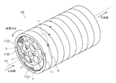
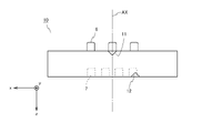
- FIG. 1 is a perspective view of the fluid activator according to the first embodiment.
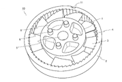
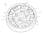
- FIG. 2 is a perspective view of a constituent unit of the fluid activator shown in FIG.
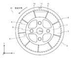
- FIG. 3 is a surface view of the constituent unit shown in FIG.
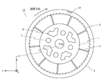
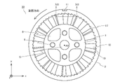
- FIG. 4 is a back view of the constituent unit shown in FIG.
- FIG. 5 is a top view of the constituent unit shown in FIG.
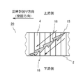
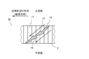
- FIG. 6 is a developed view of a cross section along the VI-VI line shown in FIG. 3 developed in a plane.
- FIG. 7 is a perspective view of a constituent unit of the fluid activator according to the second embodiment.
- FIG. 8 is a surface view of the constituent unit shown in FIG. 7.
- FIG. 9 is a developed view of a cross section along the IX-IX line shown in FIG. 8 developed in a plane.
- FIG. 10 is a perspective view of a constituent unit of the fluid activation device according to the modified example of the second embodiment.
- FIG. 11 is a surface view of the constituent unit shown in FIG.
- FIG. 12 is a developed view of a cross section along the XII-XII line shown in FIG. 11 developed in a plane.
- FIG. 13A is a partial cross-sectional view of the fluid activator according to the third embodiment.
- FIG. 13B is a cross-sectional view of the tubular body shown in FIG. 13A.
- FIG. 14 is a cross-sectional view taken along the XIV-XIV line shown in FIG. 13A.
- FIG. 15 is a partial cross-sectional view of the fluid activator according to the modified example of the third embodiment.
- FIG. 15 is a partial cross-sectional view of the fluid activator according to the modified example of the third embodiment.
- FIG. 16 is a partial cross-sectional view of the fluid activator according to the fourth embodiment.
- FIG. 17A is a cross-sectional view of the fluid activator according to the fifth embodiment.
- FIG. 17B is a cross-sectional view of the fluid activator according to the first modification of the fifth embodiment.
- FIG. 17C is a cross-sectional view of the fluid activator according to the second modification of the fifth embodiment.
- FIG. 17D is a cross-sectional view of the fluid activator according to the third modification of the fifth embodiment.
- FIG. 18 is a cross-sectional view of the fluid activator according to the sixth embodiment.
- FIG. 19 is a schematic view of the fluid activation device according to the seventh embodiment.
- FIG. 20 is a schematic view of the fluid activation device according to the eighth embodiment.
- FIG. 19 is a schematic view of the fluid activation device according to the seventh embodiment.
- FIG. 20 is a schematic view of the fluid activation device according to the eighth embodiment.
- FIG. 21 is a schematic view of a constituent unit of the fluid activator according to the ninth embodiment.
- FIG. 22 is a schematic view of a constituent unit of the fluid activation device according to the modified example of the ninth embodiment.
- FIG. 23 is a schematic view of the fluid activation device according to the tenth embodiment.
- fluid is a general term for liquids and gases.
- activation of fluid means that when the fluid is a liquid, a large number of ultrafine bubbles are generated in the liquid.
- fluid activation means reducing the size (number of molecules) of clusters, which are a collection of multiple (for example, several to several tens) gas molecules existing in the gas phase. To do.
- the cluster size of each gas becomes smaller and the clusters of each gas are uniformly mixed.
- the fuel gas and air oxygen in the air
- the fuel gas cluster and the oxygen cluster are uniformly distributed in the gas phase, so that the fuel gas molecule and the fuel gas molecule Bonding with oxygen molecules can be efficiently generated, and combustion efficiency can be dramatically improved.
- an apparatus for generating ultrafine bubbles in a liquid will be described as an example, but the fluid activator according to each of the following embodiments can also be applied to gas activation.
- FIG. 1 is a perspective view of the fluid activator according to the first embodiment.
- the fluid activation device 100 has a tubular shape as a whole and is a device that activates the supplied fluid.
- the fluid activator 100 is connected in the middle of piping such as a pipe or a tube so that the left end of FIG. 1 is on the upstream side and the right end of FIG. 1 is on the downstream side.
- the fluid activator 100 includes a cylindrical shaft 21, a tubular body 22 accommodating the shaft 21, and a plurality of blades 3 provided between the outer peripheral surface of the shaft 21 and the inner peripheral surface of the tubular body 22.
- the fluid activation device 100 is configured by combining a plurality of units 10 having the same shape, the shaft 21 is composed of a plurality of cores 1 of the plurality of units 10, and a plurality of the plurality of units 10.
- the tubular body 22 is formed by the peripheral wall 2 of the above.
- the tubular body 22 has a hollow portion, and the shaft 21 is housed in the hollow portion. As shown in FIG.
- a plurality of ribs 24 formed of ridges extending in the axial direction of the shaft 21 are provided on the inner peripheral surface of the tubular body 22.
- the plurality of ribs 24 are composed of a plurality of convex portions 4 of the plurality of units 10.
- FIG. 2 is a perspective view of the constituent unit of the fluid activator shown in FIG. 1
- FIG. 3 is a front view of the constituent unit shown in FIG. 2
- FIG. 4 is a back view of the constituent unit shown in FIG. 5 is a top view of the constituent unit shown in FIG. 4
- FIG. 6 is a developed view of a cross section along the VI-VI line shown in FIG. 3 developed in a plane.
- the direction may be specified in the xyz coordinate system.
- the positive direction of the z-axis corresponds to the flow direction of the fluid.
- the unit 10 includes a core 1, a peripheral wall 2, and a plurality of blades 3.
- the unit 10 can be formed, for example, by injection molding of a resin.
- Core 1 is a columnar member.
- the core 1 is provided with a through hole 5, a boss 6, and a recess 7. Further, recesses 8 and 9 are provided on the upstream side surface and the downstream side surface of the core 1 for the purpose of reducing the amount of resin, respectively.
- the through hole 5 is a circular hole that penetrates the center of the core 1.
- the through hole 5 is for forming a flow path that penetrates the fluid activation device 100 along its central axis when a plurality of cores 1 are connected as shown in FIG. 1 to form the fluid activation device 100. belongs to.
- This flow path is provided so that another liquid or gas can be supplied to the fluid (fluid containing a large number of ultrafine bubbles) flowing out from the fluid activation device 100.
- the through hole 5 may be closed or the through hole 5 may be omitted.
- the boss 6 is provided on both sides of the core 1 on the upstream side of the fluid activator 100 (FIG. 3). Further, the recess 7 is provided on both sides of the core 1 on the downstream side (FIG. 4) of the fluid activator 100.
- the boss 6 and the recess 7 have a shape that can be fitted to each other, and are provided to connect adjacent cores 1.
- the recess 7 is arranged at a position rotated by a predetermined angle around the central axis AX of the core 1 with respect to the boss 6. That is, when the core 1 is viewed in a plan view from the upstream side or the downstream side of the fluid activation device 100, the boss 6 is provided at a rotational position that does not overlap with the recess 7.
- the recess 7 may be provided on the upstream surface of the core 1 and the boss 6 may be provided on the downstream surface of the core 1. Further, if adjacent cores 1 can be connected to each other, fitting portions forming a fitting structure other than the boss 6 and the recess 7 may be provided on the upstream side and downstream side surfaces. Further, when the cores 1 are joined to each other with an adhesive or the like, the fitting portion may be omitted.
- the peripheral wall 2 is a tubular or annular member coaxial with the core 1.
- the peripheral wall 2 surrounds the core 1 at a predetermined distance from the outer peripheral surface of the core 1.
- a first positioning portion 11 and a second positioning portion 12 are provided on the outer surface of the peripheral wall 2 (FIGS. 3 to 5).
- the first positioning unit 11 and the second positioning unit 12 are provided so that when the cores 1 are combined, the relative rotation positions of the adjacent cores 1 can be easily aligned. Details of the first positioning unit 11 and the second positioning unit 12 will be described later.
- a plurality of convex portions 4 are provided on the inner peripheral surface of the peripheral wall 2.
- the convex portion 4 is composed of a convex strip extending in the central axis AX direction of the core 1. As shown in FIGS.
- each convex portion 4 parallel to the plane orthogonal to the central axis AX of the core 1 (hereinafter referred to as “xy plane”) is triangular.
- a plurality of convex portions 4 are provided without gaps over the entire circumference of the peripheral wall 2 in the circumferential direction, and the cross section of the plurality of convex portions 4 is saw blade-shaped on a plane parallel to the xy plane. Further, as shown in FIGS. 3 and 4, the convex portion 4 is provided on both the upstream side (front surface side) and the downstream side (back surface side) of the blade 3.
- the height of the convex portion 4 on the cross section parallel to the xy plane, the size of the apex angle, and the lengths of the two sides excluding the bottom are not particularly limited, and the viscosity and flow velocity of the fluid supplied to the fluid activator 100 are not particularly limited. , Can be set based on the pressure applied to the fluid, the permissible pressure loss, etc.
- the height of the convex portion 4 means the maximum height of the convex portion 4 in the radial direction of the peripheral wall 2 on a cross section parallel to the xy plane.
- the size of the apex angle and the length of each of the two sides excluding the base also refer to the values on the cross section parallel to the xy plane.
- the cross-sectional shape of the convex portion 4 does not have to be triangular. For example, one or both of the slopes of the convex portion 4 may be curved surfaces.
- the plurality of blades 3 swirl the fluid flowing in the space between the outer peripheral surface of the core 1 and the inner peripheral surface of the peripheral wall 2 around the central axis AX of the core 1. Further, the plurality of blades 3 are members that generate ultrafine bubbles by generating turbulent flow in the fluid.
- Each of the blades 3 connects the outer peripheral surface of the core 1 and the inner peripheral surface of the peripheral wall 2.
- the blade 3 may be connected to either the outer peripheral surface of the core 1 or the inner peripheral surface of the peripheral wall 2, but is connected to both the outer peripheral surface of the core 1 and the inner peripheral surface of the peripheral wall 2. , The strength of the blade 3 is improved.
- Each of the blades 3 is provided at a constant pitch in the circumferential direction of the core 1.
- Each of the blades 3 is arranged so as to be inclined at a predetermined angle with respect to the central axis AX of the core 1. Specifically, each of the blades 3 is directed toward the turning direction of the flow path (in the present embodiment, the counterclockwise direction centered on the central axis AX of the core 1 when viewed from the upstream side). It is inclined so that the vertical distance from the plane P including the surface on the upstream side of 1 to the surface (surface on the upstream side) of the blade 3 increases (FIG. 6). The tilt angle of each of the blades 3 is the same.
- the surface of the blade 3 may be flat or curved. As shown in FIG.
- the blade 3 has a flat plate-shaped main surface portion 13 and a bent portion 14 provided along the downstream end edge of the main surface portion.
- the upstream edge of the main surface portion 13 is preferably formed in a thin blade shape in order to reduce fluid resistance.
- the bent portion 14 generates a turbulent flow (vortex) in the fluid flowing along the surface on the downstream side of the blade 3. It is considered that ultrafine bubbles are generated due to the turbulence generated by the bent portion 14.
- the number and inclination angles of the blades 3 are not particularly limited, and can be set based on the viscosity and flow velocity of the fluid supplied to the fluid activator 100, the pressure applied to the fluid, the allowable pressure loss, and the like.
- the fluid activator 100 will be further described with reference to FIG. 1 again.
- the fluid activation device 100 shown in FIG. 1 is configured by connecting a plurality of units 10 in the direction of the central axis AX of the core 1.
- the boss 6 and the recess 7 are provided on the upstream surface (FIG. 3) and the downstream surface (FIG. 4) of the core 1, respectively. Therefore, the two units 10 can be connected by fitting the boss 6 of another unit 10 into the recess 7 of one unit 10.
- the fluid activation device 100 can be configured by connecting another unit to the connected unit 10 one after another.
- the number of units 10 constituting the fluid activation device 100 is not particularly limited.
- the recess 7 is arranged at a rotational position rotated by a predetermined angle around the central axis AX of the core 1 with respect to the boss 6. Therefore, when the plurality of units 10 are connected by fitting the boss 6 and the recess 7, each of the plurality of units 10 sequentially AX the central axis of the core 1 from the upstream side to the downstream side of the fluid activator 100. It is arranged around the wheel by rotating it in a certain direction of rotation by a certain rotation angle. For example, in the example of FIG. 1, the unit 10 on the downstream side of the two adjacent units 10 is counterclockwise around the central axis of the core 1 when viewed from the upstream side with respect to the unit 10 on the upstream side.
- a first positioning portion 11 and a second positioning portion 12 are provided on the outer peripheral surface of the peripheral wall 2.
- the second positioning unit 12 is provided at a rotational position that is rotated counterclockwise by a certain angle with respect to the first positioning unit 11 with respect to the first positioning unit 11 when viewed from the upstream side of the unit 10. Has been done. Therefore, as shown in FIG. 1, when connecting a pair of adjacent units 10, the second positioning unit 12 of the upstream unit 10 and the first positioning unit 11 of the downstream unit 10 rotate in the same manner. Place in position. As a result, the unit 10 on the downstream side can be arranged at a rotation position rotated by a certain rotation angle in a certain rotation direction with respect to the unit 10 on the upstream side.
- the relative rotation angle of the first positioning portion 11 and the second positioning portion 12 around the central axis AX and the relative rotation angle of the recess 7 with respect to the boss 6 around the central axis AX are set to be equal. There is. Therefore, when the second positioning portion 12 of the upstream unit 10 and the first positioning portion 11 of the downstream unit 10 are aligned, the recess 7 of the upstream unit 10 and the downstream unit 10 The boss 6 and the boss 6 have a positional relationship in which they can be fitted.
- each unit is shifted in the same direction by a designed constant rotation angle.
- the boss 6 and the recess 7 can be aligned with each other.
- the plurality of connected units 10 may be fixed with an adhesive, a fixing tool, or the like.
- the fluid activation device 100 is attached in the middle of the piping.
- a supply pipe for supplying the gas is connected to the flow path formed by the through hole 5 provided in the core 1.
- the flow path formed by the through hole 5 is closed.
- Fluid is supplied to the fluid activation device 100 from the piping on the upstream side.
- the fluid may be a liquid or a gas.
- you may supply a plurality of kinds of fluids together.
- the plurality of types of fluids can be uniformly mixed by the action of the fluid activator.
- different kinds of liquids may be supplied, different kinds of gases may be supplied, or liquids and gases may be supplied.
- the fluid is a liquid and ultrafine bubbles are generated in the liquid will be described.
- the fluid supplied to the space sandwiched between the core 1 and the peripheral wall 2 passes between the blades 3 adjacent in the circumferential direction and flows to the unit 10 on the downstream side.
- ultrafine bubbles are generated in the fluid due to the turbulent flow generated by the bent portion 14 of the blade 3 shown in FIG.
- the rotation position of the blade 3 of each unit is deviated by a certain angle in the counterclockwise direction about the central axis AX when viewed from the upstream side, so that the blades 3 are adjacent to each other in the circumferential direction.
- the spaces between the blades 3 are connected in order to form a flow path extending in a counterclockwise spiral. Since the fluid collides with the bent portion 14 of the blade 3 a plurality of times while flowing through the spiral flow path, ultrafine bubbles are repeatedly generated.
- the fluid activation device 100 is provided with a plurality of convex portions 4 on the inner peripheral surface of the peripheral wall 2.
- a turbulent flow vortex
- the turbulent flow further generates an ultrafine bubble.
- a plurality of convex portions 4 are provided inside the peripheral wall 2 (cylindrical body 22), and not only the collision between the fluid and the blade 3 but also the fluid and the convex portion 4 are provided. Ultrafine bubbles can also be generated by collision with the portion 4 (rib 24). Since the plurality of blades 3 generate a swirling flow, centrifugal force acts on the fluid flowing near the inner peripheral surface of the peripheral wall 2. By providing the plurality of convex portions 4 on the inner peripheral surface of the peripheral wall 2, the centrifugal force acting on the fluid can be utilized, so that the efficiency of generating ultrafine bubbles can be improved.
- the height of each of the plurality of convex portions 4 (ribs 24) monotonically increases to a predetermined height toward the turning direction of the spiral flow path, and then rapidly decreases at the ridgeline portion.
- the height of each convex portion 4 (rib 24) is from the connection portion between the respective convex portion 4 (rib 24) and the rib adjacent to the upstream side in the turning direction of the spiral flow path. It increases to the connection part between the convex portion 4 (rib 24) of the spiral flow path and the rib adjacent to the downstream side in the turning direction of the spiral flow path, and each convex portion 4 (rib 24) and each convex portion 4 (rib).
- a step is formed at the connection portion between 24) and the rib adjacent to the spiral flow path on the downstream side in the turning direction.
- the cross section of the convex portion 4 (rib 24) along the plane orthogonal to the central axis AX of the core is triangular.
- the convex portion 4 (rib 24) is provided on the entire inner peripheral surface of the peripheral wall 2 without any gap. The shape and arrangement of the convex portions 4 also improve the efficiency of generating ultrafine bubbles.
- the boss 6 and the recess 7 provided in the core 1 are provided in a positional relationship rotated by a certain angle. Therefore, when the pair of adjacent units 10 are connected by fitting the boss 6 and the recess 7, the blade 3 of one unit 10 and the blade 3 of the other unit 10 can be arranged by shifting them by a predetermined angle. can. Therefore, with the unit 10 according to the present embodiment, the fluid activation device 100 can be easily assembled.
- the second positioning portion 12 provided on the upstream unit 10 and the first positioning portion 11 provided on the downstream unit 10 are formed around the peripheral wall 2. Place them in the same rotation position in the direction. As a result, the blade 3 of the unit 10 on the upstream side and the blade 3 of the unit 10 on the downstream side can be arranged by shifting them by a predetermined angle. Further, since the first positioning unit 11 and the second positioning unit 12 correspond to the relative rotation positions of the boss 6 and the recess 7, they are based on the first positioning unit 11 and the second positioning unit 12. Therefore, it becomes easy to align the boss 6 and the recess 7 with a matable positional relationship. Therefore, the first positioning unit 11 and the second positioning unit 12 can further facilitate the assembly of the fluid activation device 100.
- FIG. 7 is a perspective view of a constituent unit of the fluid activator according to the second embodiment
- FIG. 8 is a surface view of the constituent unit shown in FIG. 7
- FIG. 9 is an IX-shown in FIG. It is a development view which developed the cross section along the IX line into a plane.
- the differences between the present embodiment and the first embodiment will be mainly described.
- the fluid activation device is composed of a combination of a plurality of units 20.
- the unit 20 includes a plurality of blades 15 having a shape different from that of the first embodiment.
- a plurality of convex portions 16 extending in the radial direction of the unit 20 are provided on the front surface and the back surface of the blade 15.
- each of the convex portions 16 has a triangular cross section.
- the convex portion 16 may be provided on one of the front surface and the back surface of the blade 15, but by providing the convex portion 16 on both sides of the blade 15, the efficiency of generating ultrafine bubbles can be further improved.
- a plurality of units 20 are connected in the central axis AX direction as in the first embodiment to form a fluid activation device.
- the fluid supplied to the space between the shaft formed by the core 1 and the tubular body formed by the peripheral wall 2 flows downstream along the front surface and the back surface of the blade 15.
- turbulence is generated in the vicinity of the ridgeline of the convex portions 16, and a large number of ultrafine bubbles are generated due to the turbulent flow.
- microbubbles are also generated when the fluid collides with the convex portion 4 provided on the inner peripheral surface of the peripheral wall 2. Therefore, according to the present embodiment, it is possible to provide a fluid activation device having excellent efficiency of generating ultrafine bubbles.
- the convex portion 16 provided on the blade 15 has a predetermined thickness toward the turning direction of the spiral flow path formed by the blade 15. After increasing to the thickness of, the thickness is rapidly reduced at the connecting portion with the adjacent convex portion 16.
- the convex portion 4 provided on any of the inner peripheral surfaces of the peripheral wall 2 has a diameter of the peripheral wall 2 as it goes toward the turning direction of the spiral flow path formed by the blade 15. After the height in the direction increases to a predetermined height, the height is sharply decreased at the connecting portion with the adjacent convex portion 4.
- FIG. 10 is a perspective view of the constituent unit of the fluid activator according to the modified example of the second embodiment
- FIG. 11 is a surface view of the constituent unit shown in FIG. 10
- FIG. 12 is shown in FIG. It is a developed view which developed the cross section along the XII-XII line shown in a plane.
- the fluid activation device is composed of a combination of a plurality of units 30.
- the unit 30 includes a blade 18 having a saw blade-like cross section as in the second embodiment, but has the shape of the convex portion 4 provided on the peripheral wall 2 and the shape of the convex portion 19 provided on the blade 18. Is different from the second embodiment.
- a plurality of convex portions 19 extending in the radial direction of the peripheral wall 2 are provided on the front surface and the back surface of the blade 18.
- the thickness of the convex portion 19 decreases from a predetermined thickness toward the turning direction of the spiral flow path formed by the blade 18, and then the thickness is formed at the connecting portion with the adjacent convex portion 19. Is configured to rapidly increase to a predetermined thickness.
- the height of the convex portion 17 provided on the inner peripheral surface of the peripheral wall 2 in the radial direction of the peripheral wall 2 decreases from a predetermined height as the spiral flow path formed by the blade 15 is directed toward the turning direction.
- the height is rapidly increased to a predetermined height at the connecting portion with the adjacent convex portion 17.
- these convex portions 17 and 19 are provided, turbulence is generated by the fluid colliding with the step formed by the convex portions 17 and 19, so that the ultra is compared with the case where the convex portions 17 and 19 are not provided.
- the efficiency of fine bubble generation can be improved.
- the combination of the convex shapes of the present modification is adopted, the flow velocity of the fluid tends to decrease due to the collision with the step, so that the combination of the convex shapes in the second embodiment shown in FIGS. 7 to 9 is used. By comparison, the efficiency of ultrafine bubble generation is low.
- the combination of the cross-sectional shape of the convex portion provided on the peripheral wall (cylindrical body) and the cross-sectional shape of the convex portion provided on the blade is not particularly limited.
- the convex portion 4 according to the second embodiment and the convex portion 19 according to the modified example may be combined, or the convex portion 17 according to the modified example and the convex portion 16 according to the second embodiment may be combined. You may.
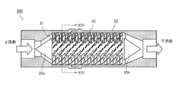
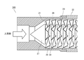
- FIG. 13A is a partial cross-sectional view of the fluid activator according to the third embodiment
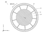
- FIG. 13B is a cross-sectional view of the cylindrical body shown in FIG. 13A
- FIG. 14 is an XIV-XIV shown in FIG. 13A. It is sectional drawing along the line.
- the fluid activator 200 includes a cylindrical shaft 21, a tubular body 22 accommodating the shaft 21, and a plurality of blades 23 provided between the outer peripheral surface of the shaft 21 and the inner peripheral surface of the tubular body 22.
- the tubular body 22 has a hollow portion, and the shaft 21 is housed in the hollow portion.
- a plurality of ribs 24 formed of ridges extending in the axial direction of the shaft 21 are provided on the inner peripheral surface of the tubular body 22.
- a space for arranging the blade 23 is formed between the outer peripheral surface of the shaft 21 and the inner peripheral surface of the tubular body 22.
- Each of the blades 23 is provided so as to be inclined at a predetermined angle with respect to the central axis of the shaft 21 as in each of the above embodiments.
- the blade 23 has the same shape as that shown in FIG. 6, but the blade 23 may be formed in a saw blade shape as in the second embodiment.
- the blades 23 are arranged at predetermined intervals in the circumferential direction and the axial direction of the shaft 21.
- the plurality of blades 23 adjacent to the shaft 21 in the axial direction rotate from the upstream side to the downstream side of the fluid activator 200 by a constant rotation angle in a constant rotation direction around the central axis of the shaft 21. Be placed.
- the arrangement of the blades 23 forms a flow path that spirally extends from the upstream side to the downstream side of the fluid activator 200.
- the materials of the shaft 21, the tubular body 22, and the blade 23 are not particularly limited, but can be formed of, for example, resin or metal.
- the shaft 21 and the blade 23 may be integrally formed by cutting or the like, or may be formed as separate members and coupled to each other.
- Conical rectifying members 25a and 25b are provided at the upstream end and the downstream end of the shaft 21, respectively.
- the rectifying member 25a is a member that allows the supplied fluid to smoothly flow into the flow path formed by the blade 23.
- the rectifying member 25b is a member that smoothly guides the fluid flowing out from the flow path formed by the blade 23 to the downstream.
- the rectifying members 25a and 25b are not always necessary and may be omitted.
- an ultrafine bubble is generated by generating a turbulent flow at the bent portion provided in the blade 23 with respect to the fluid flowing through the flow path formed by the blade 23. Let me. Further, although centrifugal force is generated in the fluid flowing through the spiral flow path formed by the blade 23, ultrafine is provided by providing a plurality of ribs 24 provided on the inner peripheral surface of the cylindrical body 22. The efficiency of bubble generation can be improved.
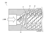
- FIG. 15 is a partial cross-sectional view of the fluid activator according to the modified example of the third embodiment.
- the fluid activation device 200 may be provided with the rectifying member 26 shown in FIG. 15 instead of the rectifying member 25a shown in FIG. 13A.
- the rectifying member 26 has a conical base portion and a spiral blade provided on the conical surface of the base portion.
- the swirling direction of the spiral blade is the same as the swirling direction of the flow path formed by the blade 23.
- FIG. 16 is a partial cross-sectional view of the fluid activator according to the fourth embodiment.
- the fluid activation device 300 includes a conical rectifying member 27 having a shaft portion 28, a plurality of spacers 29, a plurality of blade plates 38 having a plurality of blades 23, and a tubular body 22.
- the plurality of spacers 29 and the plurality of blade plates 38 are integrated in a form in which a shaft portion 28 penetrates an opening (not shown) provided at the center.
- the shaft 21 is formed by integrating the plurality of spacers 29 and a part of the plurality of blade plates 38.
- the blade plate 38 can be formed, for example, by pressing a metal plate.
- the blade 23 provided on the blade plate 38 has the same shape as that shown in FIG. 6, but the blade 23 may be formed in a saw blade shape as in the second embodiment.
- a plurality of ribs are provided on the inner peripheral surface of the tubular body 22, and the efficiency of generating ultrafine bubbles can be improved by the plurality of ribs.
- the number of ultrafine bubbles generated can be adjusted by appropriately adjusting the number of spacers 29 and blade plates 38.
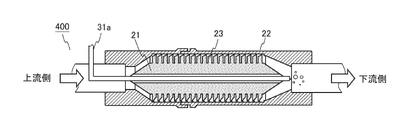
- FIG. 17A is a cross-sectional view of the fluid activator according to the fifth embodiment.
- the fluid activation device 400 further includes a supply pipe 31a for supplying a gas.
- the supply pipe 31a penetrates the through hole provided in the center of the shaft 21 from the upstream side to the downstream side, and the end portion of the supply pipe 31a is arranged in the vicinity of the downstream end portion of the shaft 21.
- the supply pipe 31a When a fluid is supplied to the fluid activation device 400, the supply pipe 31a is depressurized by the flow of the fluid, so that the gas is drawn into the fluid through the supply pipe 31a.
- the gas drawn from the supply pipe 31a is caught in the swirling flow of the fluid near the downstream end of the fluid activator 400, and the fluid is formed as a microbubble having a diameter of 1 to 100 ⁇ m or a bubble having a size larger than that. Introduced in.
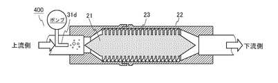
- 17B to 17D are cross-sectional views of the fluid activation device according to the first to third modifications of the fifth embodiment.
- the supply pipe 31b does not penetrate the shaft 21 and is provided on the downstream side of the shaft 21.
- the end portion of the supply pipe 31b is arranged near the downstream end portion of the shaft 21.
- the shaft 21 is provided with an L-shaped flow path from the upstream end portion through the central portion of the shaft 21 to the outer peripheral surface of the shaft 21, and the L-shaped flow path is provided.
- the end of the supply pipe 31c is arranged in the road.
- the end of the supply pipe 31d is arranged on the upstream side of the upstream end of the shaft 21.
- Gas is supplied to the supply pipe 31d by a pump.
- the gas supplied from the supply pipe 31d is caught in the swirling flow formed by the blade 23 and is taken into the fluid as an ultrafine bubble. Also with this configuration, it is possible to obtain a fluid containing a high concentration of ultrafine bubbles of gas supplied from the supply pipe 31d.
- a plurality of ribs are provided on the inner peripheral surface of the tubular body 22. Therefore, as in each of the above embodiments, the centrifugal force acting on the fluid can be utilized to improve the efficiency of generating ultrafine bubbles by the plurality of ribs.
- the type of gas supplied in the fluid activator shown in FIGS. 17A to 17D is not particularly limited. Further, the fluid activator shown in FIGS. 17A to 17D may have any of the configurations described in the first to fourth embodiments described above.
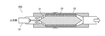
- FIG. 18 is a cross-sectional view of the fluid activator according to the sixth embodiment.
- the fluid activation device 500 further includes a drive device 32 for rotating the shaft 21.
- the drive device 32 is, for example, a motor.
- By rotating the shaft 21 while supplying the fluid to the fluid activation device 500 the number of passages of the blade 23 per unit time can be increased, so that the generation of ultrafine bubbles can be promoted.
- a plurality of ribs (not shown) are provided on the inner peripheral surface of the tubular body 22. Therefore, as in each of the above embodiments, the centrifugal force acting on the fluid can be utilized to improve the efficiency of generating ultrafine bubbles by the plurality of ribs.
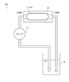
- FIG. 19 is a schematic view of the fluid activation device according to the seventh embodiment.
- the fluid activation device 600 includes a shaft 21, a cylindrical body 22, a blade 23, an accommodating portion 33 accommodating them, and a motor 34 attached to the shaft 21.
- the accommodating portion 33 is provided with an inflow pipe 35a for inflowing the fluid and an outflow pipe 35b for guiding the fluid to the outside.
- the motor 34 rotates the shaft 21 to efficiently generate ultrafine bubbles.
- a plurality of ribs are provided on the inner peripheral surface of the tubular body 22. Therefore, as in each of the above embodiments, the centrifugal force acting on the fluid can be utilized to improve the efficiency of generating ultrafine bubbles by the plurality of ribs.
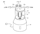
- FIG. 20 is a schematic view of the fluid activation device according to the eighth embodiment.
- the fluid activation device 700 includes a shaft 21, a cylindrical body 22, a blade 23, a storage tank 36, and a pump 37.
- the fluid in the storage tank 36 is supplied into the tubular body 22 by the pump 37, and the fluid discharged from the tubular body 22 is returned to the storage tank 36.
- the concentration of ultrafine bubbles can be improved by circulating the fluid in the storage tank 36 and repeatedly supplying the fluid to the tubular body 22.
- a plurality of ribs (not shown) are provided on the inner peripheral surface of the tubular body 22. Therefore, as in each of the above embodiments, the centrifugal force acting on the fluid can be utilized to improve the efficiency of generating ultrafine bubbles by the plurality of ribs.
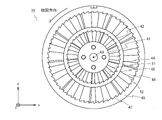
- FIG. 21 is a schematic view of a constituent unit of the fluid activator according to the ninth embodiment.
- the unit 40 has a structure in which the unit 10 is nested in the core 1 portion of the unit 10 according to the first embodiment.
- the unit 40 includes a core 41, a first peripheral wall 42, a plurality of first blades 43, a plurality of first convex portions 44, a second peripheral wall 45, and a plurality of second blades 46.
- a plurality of second convex portions 47 are provided.
- the core 41 is a columnar member.
- a through hole may be provided in the central portion of the core 41 as in the first embodiment.
- the first peripheral wall 42 is a tubular or annular member coaxial with the core 41.
- the first peripheral wall 42 surrounds the core 41 at a predetermined distance from the outer peripheral surface of the core 41.
- the plurality of first blades 43 have the same shape as the blade 3 (FIG. 6) of the first embodiment, and are connected to the outer peripheral surface of the core 41 and the inner peripheral surface of the first peripheral wall 42.
- the plurality of blades 43 form a flow path extending spirally in the first cylindrical body formed by the plurality of first peripheral walls 42, and the core 41 and the first peripheral wall 42 The fluid flowing between them is swirled around the central axis AX of the core 41. Further, the plurality of first blades 43 generate ultrafine bubbles by generating turbulent flow in the fluid.
- the plurality of first convex portions 44 are convex strips extending in the central axis AX direction of the core 1, and are configured in the same manner as the convex portions 4 of the first embodiment. A plurality of first convex portions 44 are provided without gaps over the entire circumference of the first peripheral wall 42 in the circumferential direction.
- the second peripheral wall 45 surrounds the first peripheral wall 42 at a predetermined distance from the outer peripheral surface of the first peripheral wall 42.
- the plurality of second blades 46 have the same shape as the blade 3 (FIG. 6) of the first embodiment, and are connected to the outer peripheral surface of the first peripheral wall 42 and the inner peripheral surface of the second peripheral wall 45. To. Similar to the blade 3 described above, the plurality of second blades 46 form a flow path extending spirally in the second cylindrical body formed by the plurality of second peripheral walls 45, and together with the first peripheral wall 42. The fluid flowing between the second peripheral wall 45 is swirled around the central axis AX of the core 41. Further, the plurality of second blades 46 generate ultrafine bubbles by generating turbulent flow in the fluid.
- the plurality of second convex portions 47 are convex stripes extending in the central axis AX direction of the core 1, and are configured in the same manner as the convex portions 4 of the first embodiment.
- a plurality of second convex portions 47 are provided without gaps over the entire circumference of the second peripheral wall 45 in the circumferential direction.
- the unit 40 may be provided with the first positioning unit 11 and the second positioning unit 12 described in the first embodiment. Further, the unit 40 may be provided with the boss 6 and the recess 7 described in the first embodiment.
- the fluid activation device is configured by connecting a plurality of units 40 so that the central axes AX coincide with each other.
- a plurality of cores 41 of a plurality of units 40 form a shaft of a fluid activator
- a plurality of first peripheral walls 42 of the plurality of units 40 form a first cylindrical body
- a second of the plurality of units 40 form a second tubular body.
- the inside of the second peripheral wall 45 is divided concentrically, and the inner peripheral surface of the first peripheral wall 42 (first cylindrical body) is divided into concentric circles.
- a plurality of first convex portions 44 and a plurality of second convex portions 47 are provided on the inner peripheral surface of the second peripheral wall 45 (second tubular body). Therefore, the first convex portion 44 on the inner peripheral surface of the first peripheral wall 42 and the second convex portion 47 on the inner peripheral surface of the second peripheral wall 45 increase the amount of ultrafine bubbles generated.
- the unit 40 having a nested structure can be particularly suitably applied to a fluid activator having a large diameter, and can improve the efficiency of generating ultrafine bubbles in a fluid activator having a large diameter.
- FIG. 22 is a schematic view of a constituent unit of the fluid activation device according to the modified example of the ninth embodiment.
- the unit 50 shown in FIG. 22 replaces the plurality of first blades 43 and the plurality of second blades 46 of the unit 40 shown in FIG. 22 with the plurality of first blades 48 and the plurality of second blades 49. Is provided.
- the first blade 48 and the second blade 49 have the same shape as the blade 15 (FIG. 9) shown in the second embodiment. That is, a plurality of convex portions 51 and 52 extending in the radial direction of the unit 50 are provided on the front surface and the back surface of the first blade 48 and the second blade 49.
- the convex portions 51 and 52 have the same shape as the convex portions 16 (FIG. 9) of the second embodiment.
- the fluid flowing while swirling inside the fluid activator is formed in a plurality of convex portions 51 provided on the front and back surfaces of the first blade 48 and a plurality of convex portions 52 provided on the front and back surfaces of the second blade 49. collide. At this time, turbulence is generated near the ridges of the convex portions 51 and 52, and a large number of ultrafine bubbles are generated due to the turbulence. Therefore, when the fluid activation device is configured by the unit 50 according to the present embodiment, the efficiency of generating ultrafine bubbles can be further improved as compared with the case where the unit 40 shown in FIG. 22 is used.
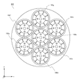
- FIG. 23 is a schematic view of the fluid activation device according to the tenth embodiment.
- the fluid activator 800 is the same fluid activator 100a to 100 g as the fluid activator 100 according to the first embodiment arranged in parallel.
- the fluid activators 100a to 100b are arranged so that their central axes are parallel to each other and are fixed to each other.
- the means for fixing the fluid activator 100a to 100g is not particularly limited.
- a large-diameter fluid activator 800 can be realized by combining relatively small-diameter fluid activators 100a to 100 g. Further, by changing the number of small-diameter fluid activators to be combined, the cross-sectional shape and cross-sectional size of the fluid activator 800 can be easily changed.
- a plurality of fluid activators according to any of the second, third and ninth embodiments may be arranged in parallel.
- the present invention can be used for a fluid activator.
Abstract
Description
図1は、第1の実施形態に係る流体活性化装置の斜視図である。 (First Embodiment)
FIG. 1 is a perspective view of the fluid activator according to the first embodiment.
図7は、第2の実施形態に係る流体活性化装置の構成ユニットの斜視図であり、図8は、図7に示す構成ユニットの表面図であり、図9は、図8に示すIX-IXラインに沿う断面を平面に展開した展開図である。以下、本実施形態と第1の実施形態との相違点を中心に説明する。 (Second embodiment)
7 is a perspective view of a constituent unit of the fluid activator according to the second embodiment, FIG. 8 is a surface view of the constituent unit shown in FIG. 7, and FIG. 9 is an IX-shown in FIG. It is a development view which developed the cross section along the IX line into a plane. Hereinafter, the differences between the present embodiment and the first embodiment will be mainly described.
図10は、第2の実施形態の変形例に係る流体活性化装置の構成ユニットの斜視図であり、図11は、図10に示す構成ユニットの表面図であり、図12は、図11に示すXII-XIIラインに沿う断面を平面に展開した展開図である。 (Modified example of the second embodiment)
10 is a perspective view of the constituent unit of the fluid activator according to the modified example of the second embodiment, FIG. 11 is a surface view of the constituent unit shown in FIG. 10, and FIG. 12 is shown in FIG. It is a developed view which developed the cross section along the XII-XII line shown in a plane.
図13Aは、第3の実施形態に係る流体活性化装置の部分断面図であり、図13Bは、図13Aに示す筒状体の断面図であり、図14は、図13Aに示すXIV-XIVラインに沿う断面図である。 (Third Embodiment)
13A is a partial cross-sectional view of the fluid activator according to the third embodiment, FIG. 13B is a cross-sectional view of the cylindrical body shown in FIG. 13A, and FIG. 14 is an XIV-XIV shown in FIG. 13A. It is sectional drawing along the line.
図16は、第4の実施形態に係る流体活性化装置の部分断面図である。 (Fourth Embodiment)
FIG. 16 is a partial cross-sectional view of the fluid activator according to the fourth embodiment.
図17Aは、第5の実施形態に係る流体活性化装置の断面図である。 (Fifth Embodiment)
FIG. 17A is a cross-sectional view of the fluid activator according to the fifth embodiment.
図18は、第6の実施形態に係る流体活性化装置の断面図である。 (Sixth Embodiment)
FIG. 18 is a cross-sectional view of the fluid activator according to the sixth embodiment.
図19は、第7の実施形態に係る流体活性化装置の概略図である。 (7th Embodiment)
FIG. 19 is a schematic view of the fluid activation device according to the seventh embodiment.
図20は、第8の実施形態に係る流体活性化装置の概略図である。 (8th Embodiment)
FIG. 20 is a schematic view of the fluid activation device according to the eighth embodiment.
図21は、第9の実施形態に係る流体活性化装置の構成ユニットの概略図である。 (9th Embodiment)
FIG. 21 is a schematic view of a constituent unit of the fluid activator according to the ninth embodiment.
図23は、第10の実施形態に係る流体活性化装置の概略図である。 (10th Embodiment)
FIG. 23 is a schematic view of the fluid activation device according to the tenth embodiment.
2 周壁
3 ブレード
4 リブ
6 ボス
7 凹部
10 ユニット
11 第1の位置決め部
12 第2の位置決め部
15 ブレード
16 凸条
20 ユニット
21 シャフト
22 筒状体
23 ブレード
24 リブ
30 ユニット
40 ユニット
41 コア
42 第1の周壁
43 第1のブレード
44 第1の凸部
45 第2の周壁
46 第2のブレード
47 第2の凸部
48 第1のブレード
49 第2のブレード
51、52 凸部
100、200、300、400、500、600、700、800 流体活性化装置
1
Claims (10)
- 円柱状のシャフトと、
中空部を有し、前記中空部の内周面と前記シャフトの外周面との間に所定間隔を空けて前記シャフトを収容する筒状体と、
前記シャフトの外周面と前記筒状体の内周面との間に設けられ、前記筒状体の一方端側から他方端側に向かって螺旋状に延びる流路を形成すると共に、前記流路を流れる流体に乱流を発生させる複数のブレードとを備え、
筒状体の内周面には、前記シャフトの軸方向に延びる凸条からなる複数のリブが設けられる、流体活性化装置。 Cylindrical shaft and
A cylindrical body having a hollow portion and accommodating the shaft at a predetermined distance between the inner peripheral surface of the hollow portion and the outer peripheral surface of the shaft.
A flow path provided between the outer peripheral surface of the shaft and the inner peripheral surface of the tubular body and spirally extending from one end side to the other end side of the tubular body is formed, and the flow path is formed. Equipped with multiple blades that generate turbulence in the flowing fluid,
A fluid activation device in which a plurality of ribs formed of ridges extending in the axial direction of the shaft are provided on the inner peripheral surface of the tubular body. - 前記複数のリブが、前記周壁の前記内周面の全面に設けられる、請求項1に記載の流体活性化装置。 The fluid activation device according to claim 1, wherein the plurality of ribs are provided on the entire surface of the inner peripheral surface of the peripheral wall.
- 前記複数のリブの各々の高さが、前記流路の旋回方向の反対側に隣接するリブとの接続部から、前記流路の旋回方向側に隣接するリブとの接続部にかけて、前記流路の旋回方向に向かうにつれて増加し、前記複数のリブの各々と、前記流路の旋回方向側に隣接するリブとの接続部に段差が設けられる、請求項1または2に記載の流体活性化装置。 The height of each of the plurality of ribs extends from the connection portion with the rib adjacent to the swirl direction side of the flow path to the connection portion with the rib adjacent to the swirl direction side of the flow path. The fluid activation device according to claim 1 or 2, wherein the number of ribs increases toward the swirling direction of the fluid, and a step is provided at a connection portion between each of the plurality of ribs and a rib adjacent to the swirling direction side of the flow path. ..
- 前記複数のブレードの各々は、前記筒状体の径方向に延びる複数の凸部を有し、
前記流路の旋回方向に向かうにつれて、前記複数のブレードの各々に設けられた前記複数の凸部の厚みが所定の厚みまで増加した後、隣接する凸部との接続部で急減する、請求項1または2に記載の流体活性化装置。 Each of the plurality of blades has a plurality of convex portions extending in the radial direction of the tubular body.
The claim that the thickness of the plurality of convex portions provided on each of the plurality of blades increases to a predetermined thickness as the flow direction is swirled, and then rapidly decreases at a connection portion with an adjacent convex portion. The fluid activator according to 1 or 2. - 前記複数のブレードの各々の断面が鋸刃状である、請求項1~4のいずれかに記載の流体活性化装置。 The fluid activation device according to any one of claims 1 to 4, wherein each of the plurality of blades has a saw blade shape.
- 前記流体活性化装置は、同一形状を有する複数のユニットから構成されており、
前記複数のユニットの各々は、
円柱状のコアと、
前記コアと同軸であり、前記コアの外周面との間に所定間隔を空けて前記コアを取り囲む筒状の周壁と、
前記コアの外周面及び/または前記周壁の内周面に接続され、前記コアの周方向に所定のピッチで配置される複数の前記ブレードとを備え、
前記周壁の内周面に、前記複数のリブを構成する複数の凸部が設けられる、請求項1~5のいずれかに記載の流体活性化装置。 The fluid activator is composed of a plurality of units having the same shape.
Each of the plurality of units
With a columnar core
A cylindrical peripheral wall that is coaxial with the core and surrounds the core at a predetermined distance from the outer peripheral surface of the core.
A plurality of the blades connected to the outer peripheral surface of the core and / or the inner peripheral surface of the peripheral wall and arranged at a predetermined pitch in the circumferential direction of the core are provided.
The fluid activation device according to any one of claims 1 to 5, wherein a plurality of convex portions forming the plurality of ribs are provided on the inner peripheral surface of the peripheral wall. - 前記複数のユニットの各々は、前記流体活性化装置の一方端側から他方端側に向かって順に、前記コアの中心軸の周りに一定の回転方向に一定の回転角度ずつ回転して配置されており、
前記周壁の内側に、前記流体活性化装置の前記一方端側から前記他方端側へと螺旋状に延びる前記流路が形成される、請求項6に記載の流体活性化装置。 Each of the plurality of units is sequentially arranged from one end side to the other end side of the fluid activator by rotating around the central axis of the core by a constant rotation angle in a constant rotation direction. Ori,
The fluid activation device according to claim 6, wherein the flow path spirally extending from the one end side of the fluid activation device to the other end side is formed inside the peripheral wall. - 前記コアの両面のうち、前記流体活性化装置の前記一方端側の面に第1の嵌合部が設けられ、前記流体活性化装置の前記他方端側の面に前記第1の嵌合部と嵌合可能な第2の嵌合部が設けられ、
前記第2の嵌合部は、前記第1の嵌合部に対して、前記コアの中心軸の周りに前記一定の回転方向に前記一定の回転角度だけ回転した回転位置に設けられる、請求項7に記載の流体活性化装置。 Of both sides of the core, a first fitting portion is provided on the one end side surface of the fluid activation device, and the first fitting portion is provided on the other end side surface of the fluid activation device. A second fitting part that can be fitted with is provided,
The second fitting portion is provided at a rotational position with respect to the first fitting portion, which is rotated around the central axis of the core by the constant rotation angle in the constant rotation direction. 7. The fluid activator according to 7. - 前記周壁の外周面には、第1の位置決め部及び第2の位置決め部が設けられており、
隣接する一対のユニットの一方に設けられた前記第1の位置決め部と、前記隣接する一対のユニットの他方に設けられた前記第2の位置決め部とを、前記周壁の周方向における同一の回転位置に配置したときに、前記ユニットの前記他方が、前記ユニットの前記一方に対して、前記コアの中心軸周りに前記一定の回転方向に前記一定の回転角度だけ回転した回転位置に配置される、請求項7または8に記載の流体活性化装置。 A first positioning portion and a second positioning portion are provided on the outer peripheral surface of the peripheral wall.
The first positioning portion provided on one of a pair of adjacent units and the second positioning portion provided on the other side of the pair of adjacent units are positioned at the same rotation position in the circumferential direction of the peripheral wall. When arranged in, the other of the units is arranged at a rotation position that is rotated by the certain rotation angle in the certain rotation direction around the central axis of the core with respect to the one of the units. The fluid activator according to claim 7 or 8. - 円柱状のシャフトと、
第1の中空部を有し、前記第1の中空部の内周面と前記シャフトの外周面との間に所定間隔を空けて前記シャフトを収容する第1の筒状体と、
前記シャフトの外周面と前記第2の筒状体の内周面との間に設けられ、前記第1の筒状体の一方端側から他方端側に向かって螺旋状に延びる第1の流路を形成すると共に、前記第1の流路を流れる流体に乱流を発生させる複数の第1のブレードと、
前記第1の筒状体の内周面に設けられ、前記シャフトの軸方向に延びる凸条からなる複数の第1のリブと、
第2の中空部を有し、前記第2の中空部の内周面と前記シャフトの外周面との間に所定間隔を空けて前記第1の筒状体を収容する第2の筒状体と、
前記第1の筒状体の外周面と前記第2の筒状体の内周面との間に設けられ、前記第2の筒状体の一方端側から他方端側に向かって螺旋状に延びる第2の流路を形成すると共に、前記第2の流路を流れる流体に乱流を発生させる複数の第2のブレードと、
前記第2の筒状体の内周面に設けられ、前記シャフトの軸方向に延びる凸条からなる複数の第2のリブとを備える、流体活性化装置。 Cylindrical shaft and
A first cylindrical body having a first hollow portion and accommodating the shaft at a predetermined distance between the inner peripheral surface of the first hollow portion and the outer peripheral surface of the shaft.
A first flow that is provided between the outer peripheral surface of the shaft and the inner peripheral surface of the second tubular body and extends spirally from one end side to the other end side of the first tubular body. A plurality of first blades that form a path and generate turbulence in the fluid flowing through the first flow path.
A plurality of first ribs provided on the inner peripheral surface of the first tubular body and formed of ridges extending in the axial direction of the shaft, and a plurality of first ribs.
A second cylindrical body having a second hollow portion and accommodating the first cylindrical body at a predetermined distance between the inner peripheral surface of the second hollow portion and the outer peripheral surface of the shaft. When,
It is provided between the outer peripheral surface of the first cylindrical body and the inner peripheral surface of the second tubular body, and spirals from one end side to the other end side of the second tubular body. A plurality of second blades that form an extending second flow path and generate turbulence in the fluid flowing through the second flow path.
A fluid activation device provided on the inner peripheral surface of the second tubular body and provided with a plurality of second ribs formed of ridges extending in the axial direction of the shaft.
Priority Applications (3)
| Application Number | Priority Date | Filing Date | Title |
|---|---|---|---|
| CN202180089961.2A CN116829248A (en) | 2021-01-12 | 2021-12-22 | fluid activation device |
| EP21919700.1A EP4279168A1 (en) | 2021-01-12 | 2021-12-22 | Fluid activating device |
| JP2022575493A JPWO2022153813A1 (en) | 2021-01-12 | 2021-12-22 |
Applications Claiming Priority (2)
| Application Number | Priority Date | Filing Date | Title |
|---|---|---|---|
| JP2021003031A JP6990471B1 (en) | 2021-01-12 | 2021-01-12 | Ultra fine bubble generator |
| JP2021-003031 | 2021-01-12 |
Publications (1)
| Publication Number | Publication Date |
|---|---|
| WO2022153813A1 true WO2022153813A1 (en) | 2022-07-21 |
Family
ID=80185461
Family Applications (1)
| Application Number | Title | Priority Date | Filing Date |
|---|---|---|---|
| PCT/JP2021/047701 WO2022153813A1 (en) | 2021-01-12 | 2021-12-22 | Fluid activating device |
Country Status (4)
| Country | Link |
|---|---|
| EP (1) | EP4279168A1 (en) |
| JP (3) | JP6990471B1 (en) |
| CN (1) | CN116829248A (en) |
| WO (1) | WO2022153813A1 (en) |
Families Citing this family (1)
| Publication number | Priority date | Publication date | Assignee | Title |
|---|---|---|---|---|
| JP7338926B1 (en) | 2023-03-24 | 2023-09-05 | 株式会社アルベール・インターナショナル | microbubble generator |
Citations (7)
| Publication number | Priority date | Publication date | Assignee | Title |
|---|---|---|---|---|
| JPS6242728A (en) * | 1985-08-14 | 1987-02-24 | Ono Bankin Kogyosho:Kk | Fluid mixer |
| JP2007524335A (en) * | 2003-07-10 | 2007-08-23 | マグネティック アプリケーションズ インコーポレイテッド | Compact high-power alternator |
| JP2012139646A (en) * | 2010-12-29 | 2012-07-26 | Bicom:Kk | Micro nano-bubble generating apparatus, and micro nano-bubble water generating apparatus |
| JP2014195793A (en) * | 2013-03-04 | 2014-10-16 | 株式会社リコー | Fluid agitation device, fluid agitation method and toner production method |
| JP2017080721A (en) * | 2015-10-30 | 2017-05-18 | 昭義 毛利 | Ultrafine bubble generating tool |
| JP6490317B1 (en) | 2017-12-14 | 2019-03-27 | 泰平 山田 | Ultra Fine Bubble Generator |
| WO2019116642A1 (en) * | 2017-12-14 | 2019-06-20 | 泰平 山田 | Ultra-fine bubble generation device |
-
2021
- 2021-01-12 JP JP2021003031A patent/JP6990471B1/en active Active
- 2021-11-29 JP JP2021193086A patent/JP2022108258A/en active Pending
- 2021-12-22 EP EP21919700.1A patent/EP4279168A1/en active Pending
- 2021-12-22 CN CN202180089961.2A patent/CN116829248A/en active Pending
- 2021-12-22 WO PCT/JP2021/047701 patent/WO2022153813A1/en active Application Filing
- 2021-12-22 JP JP2022575493A patent/JPWO2022153813A1/ja active Pending
Patent Citations (7)
| Publication number | Priority date | Publication date | Assignee | Title |
|---|---|---|---|---|
| JPS6242728A (en) * | 1985-08-14 | 1987-02-24 | Ono Bankin Kogyosho:Kk | Fluid mixer |
| JP2007524335A (en) * | 2003-07-10 | 2007-08-23 | マグネティック アプリケーションズ インコーポレイテッド | Compact high-power alternator |
| JP2012139646A (en) * | 2010-12-29 | 2012-07-26 | Bicom:Kk | Micro nano-bubble generating apparatus, and micro nano-bubble water generating apparatus |
| JP2014195793A (en) * | 2013-03-04 | 2014-10-16 | 株式会社リコー | Fluid agitation device, fluid agitation method and toner production method |
| JP2017080721A (en) * | 2015-10-30 | 2017-05-18 | 昭義 毛利 | Ultrafine bubble generating tool |
| JP6490317B1 (en) | 2017-12-14 | 2019-03-27 | 泰平 山田 | Ultra Fine Bubble Generator |
| WO2019116642A1 (en) * | 2017-12-14 | 2019-06-20 | 泰平 山田 | Ultra-fine bubble generation device |
Also Published As
| Publication number | Publication date |
|---|---|
| JPWO2022153813A1 (en) | 2022-07-21 |
| CN116829248A (en) | 2023-09-29 |
| EP4279168A1 (en) | 2023-11-22 |
| JP2022108258A (en) | 2022-07-25 |
| JP2022108153A (en) | 2022-07-25 |
| JP6990471B1 (en) | 2022-01-12 |
Similar Documents
| Publication | Publication Date | Title |
|---|---|---|
| JP6490317B1 (en) | Ultra Fine Bubble Generator | |
| JP6048841B2 (en) | Fine bubble generator | |
| JP5748162B2 (en) | Swivel unit-based microbubble generator | |
| US8622715B1 (en) | Twin turbine asymmetrical nozzle and jet pump incorporating such nozzle | |
| WO2022153813A1 (en) | Fluid activating device | |
| WO2019116642A1 (en) | Ultra-fine bubble generation device | |
| JP6842249B2 (en) | Fine bubble generation nozzle | |
| US20190118197A1 (en) | Fluid supply apparatus | |
| WO2006019107A1 (en) | Method of generating micro air bubble in liquid and air bubble generating apparatus | |
| JP2019063986A (en) | Internal structure | |
| CN113648858A (en) | Bubble generation device and bubble generation unit | |
| JPWO2018117040A1 (en) | Apparatus and system for generating gas-liquid containing fine bubbles | |
| US20080106969A1 (en) | Fluid mixer and mixing element member | |
| JP6925020B2 (en) | Mixing device and mixing method | |
| US20210213400A1 (en) | Gas-liquid mixing device | |
| JP2020015018A (en) | Gas-liquid mixer | |
| JP6151555B2 (en) | Fluid suction mixing device | |
| WO2018134887A1 (en) | Ultrafine bubble generation tool | |
| CN209901060U (en) | Device for doping micro-nano bubbles into fluid | |
| KR20180028795A (en) | Impeller | |
| JP2011121038A (en) | Static mixer | |
| JP2021084068A (en) | Fluid supply device | |
| FI20195196A1 (en) | A mixing and dissolving tube | |
| CN211864584U (en) | Micro-power gas-liquid or liquid-liquid mixed nano-scale fluid generator | |
| KR102355532B1 (en) | Shear nozzle and fine bubble conversion module including the same |
Legal Events
| Date | Code | Title | Description |
|---|---|---|---|
| 121 | Ep: the epo has been informed by wipo that ep was designated in this application |
Ref document number: 21919700 Country of ref document: EP Kind code of ref document: A1 |
|
| ENP | Entry into the national phase |
Ref document number: 2022575493 Country of ref document: JP Kind code of ref document: A |
|
| WWE | Wipo information: entry into national phase |
Ref document number: 202180089961.2 Country of ref document: CN |
|
| NENP | Non-entry into the national phase |
Ref country code: DE |
|
| ENP | Entry into the national phase |
Ref document number: 2021919700 Country of ref document: EP Effective date: 20230814 |