WO2022153482A1 - 圧縮機 - Google Patents
圧縮機 Download PDFInfo
- Publication number
- WO2022153482A1 WO2022153482A1 PCT/JP2021/001250 JP2021001250W WO2022153482A1 WO 2022153482 A1 WO2022153482 A1 WO 2022153482A1 JP 2021001250 W JP2021001250 W JP 2021001250W WO 2022153482 A1 WO2022153482 A1 WO 2022153482A1
- Authority
- WO
- WIPO (PCT)
- Prior art keywords
- drive shaft
- oil separator
- rotor
- compressor
- discharge pipe
- Prior art date
- Legal status (The legal status is an assumption and is not a legal conclusion. Google has not performed a legal analysis and makes no representation as to the accuracy of the status listed.)
- Ceased
Links
Images



Classifications
-
- F—MECHANICAL ENGINEERING; LIGHTING; HEATING; WEAPONS; BLASTING
- F04—POSITIVE - DISPLACEMENT MACHINES FOR LIQUIDS; PUMPS FOR LIQUIDS OR ELASTIC FLUIDS
- F04B—POSITIVE-DISPLACEMENT MACHINES FOR LIQUIDS; PUMPS
- F04B39/00—Component parts, details, or accessories, of pumps or pumping systems specially adapted for elastic fluids, not otherwise provided for in, or of interest apart from, groups F04B25/00 - F04B37/00
- F04B39/04—Measures to avoid lubricant contaminating the pumped fluid
-
- F—MECHANICAL ENGINEERING; LIGHTING; HEATING; WEAPONS; BLASTING
- F04—POSITIVE - DISPLACEMENT MACHINES FOR LIQUIDS; PUMPS FOR LIQUIDS OR ELASTIC FLUIDS
- F04C—ROTARY-PISTON, OR OSCILLATING-PISTON, POSITIVE-DISPLACEMENT MACHINES FOR LIQUIDS; ROTARY-PISTON, OR OSCILLATING-PISTON, POSITIVE-DISPLACEMENT PUMPS
- F04C29/00—Component parts, details or accessories of pumps or pumping installations, not provided for in groups F04C18/00 - F04C28/00
- F04C29/02—Lubrication; Lubricant separation
Definitions
- This disclosure relates to a compressor used in an air conditioner or the like.
- the refrigerating machine oil mixed with the compressed refrigerant is discharged together with the refrigerant gas to the refrigerant system outside the compressor, which may cause a phenomenon of oil rising.
- the oil rises in the compressor the amount of oil for lubrication decreases, which may lead to failure. Therefore, in the conventional compressor, in order to prevent the oil from rising, the oil called the oil separator and the refrigerant are centrifuged directly under the discharge pipe and at the upper end of the drive shaft, and the refrigerating machine oil is separated into the inside of the compressor.
- the compressor of Patent Document 1 is an oil separator for separating the refrigerating machine oil contained in the refrigerant gas, in which a disk is provided above the rotor of the electric mechanism portion, and the disk is cut and bent up and down. It has a protruding shape.
- the disk-shaped oil separator provided in the conventional compressor separates the refrigerating machine oil contained in the refrigerant gas only by the centrifugal separation effect. Therefore, in the conventional compressor, when the flow rate of the refrigerant is large such as during high-speed operation, or when the oil is separated by a large-capacity compressor, the refrigerant gas and the refrigerating machine oil can be efficiently separated by centrifugation alone. May not be separated.
- the present disclosure is for solving such a problem, and an object of the present disclosure is to provide a compressor capable of efficiently separating a refrigerant gas and a refrigerating machine oil.
- the compressor according to the present disclosure is arranged inside a closed container constituting an outer shell, an electric mechanism unit having a stator and a rotor, and inside the closed container, and compresses the refrigerant.
- a front portion having one side and formed in a plate shape, and a second side portion having a second side portion which is an edge on the opposite side in the rotation direction, and a rear portion formed in a plate shape and an anterior portion in the rotation direction. It has a bent portion which is a portion between the portion and the rear portion and is a portion formed in a bent state of the blade plate, and the second side portion is the first side in the axial direction of the drive shaft. It is formed so as to be located on the side where the rotor is arranged rather than the portion.
- the second side portion which is one edge portion, is located below the first side portion, which is the other edge portion, in the circumferential direction. It is formed to do.
- the oil separator causes turbulence in the refrigerant gas contained in the surrounding space of the oil separator and the refrigerating machine oil contained therein to increase the Reynolds number when the oil separator rotates, thereby increasing the Reynolds number of the oil separator.
- the refrigerant gas and the refrigerating machine oil contained therein are caused to have a steep gradient in the flow velocity distribution.
- the heat transfer coefficient of the refrigerant gas and the refrigerating machine oil is increased by stirring by the blades. Since the gradients of the density changes of the refrigerant gas and the refrigerating machine oil differ depending on the temperature, the density difference between the refrigerant gas and the refrigerating machine oil increases as the temperatures of the refrigerant gas and the refrigerating machine oil rise.
- the oil separator can enhance the effect of centrifugal separation between the refrigerant gas and the refrigerating machine oil due to this density difference, and can efficiently separate the refrigerant gas and the refrigerating machine oil.
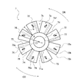
- FIG. 5 is a vertical cross-sectional view schematically showing the overall structure of the compressor according to the first embodiment. It is a schematic top view of the oil separator of the compressor which concerns on Embodiment 1. FIG. It is a schematic side view of the oil separator of the compressor which concerns on Embodiment 1. FIG. It is a schematic side view explaining the relationship between the drive shaft of the compressor and the oil separator which concerns on Embodiment 1. FIG. It is a conceptual diagram which showed the flow of the fluid which flows along the blade surface in the cross section of the blade of the oil separator of the compressor which concerns on Embodiment 1. FIG.
- FIG. 1 is a vertical cross-sectional view schematically showing the overall structure of the compressor 100 according to the first embodiment.
- the compressor 100 according to the first embodiment is a rotary type closed type compressor.
- the compressor 100 includes an electric mechanism unit 4 and a compression mechanism unit 10 that sucks and compresses the refrigerant by the rotation of the drive shaft 5 fixed to the electric mechanism unit 4, and these are arranged inside the closed container 60.
- the compressor 100 is provided in the drive shaft 5 for transmitting the rotational driving force generated in the electric mechanism unit 4 to the compression mechanism unit 10 and the drive shaft 5 inside the closed container 60, and is included in the refrigerant gas. It is provided with an oil separator 7 that separates the refrigerating machine oil from the refrigerant. Further, a suction pipe 62 and a suction pipe 63 for sucking the refrigerant are connected to the side wall portion of the closed container 60 of the compressor 100, and the compressed refrigerant is discharged to the upper wall portion of the closed container 60. A discharge pipe 64 for this purpose is provided. The discharge pipe 64 is provided above the drive shaft 5. The discharge pipe 64 is erected so as to extend perpendicular to the upper wall portion of the compressor 100, but the angle with respect to the upper wall portion is not limited to vertical.
- the closed container 60 constitutes the outer shell of the compressor 100, and forms a closed space inside the closed container 60.
- the closed container 60 is formed of, for example, a steel plate, and the side wall portion of the closed container 60 is formed in a substantially cylindrical shape.
- the electric mechanism unit 4 includes an annular stator 2 fixed to the closed container 60, and a rotor 3 arranged inside the stator 2 with an inner peripheral surface of the stator 2 and a predetermined gap. ing.
- the rotor 3 is rotatably arranged with respect to the stator 2.
- the rotor 3 is formed in a columnar shape, and a drive shaft 5 is fixed to the central portion of the rotor 3.
- the rotor 3 is formed with a through hole 3a that allows the space above the rotor 3 and the space below the rotor 3 to communicate with each other.
- the electric mechanism portion 4 is arranged in the upper space in the closed container 60, and is arranged above the compression mechanism portion 10.
- the electric mechanism unit 4 is driven by being supplied with electric power from the outside via an airtight terminal (not shown).
- a magnetic field is generated when a current flows through the stator 2, and the rotor 3 is rotationally driven by the magnetic field generated in the stator 2.
- the compressor 100 when the electric mechanism unit 4 is driven, the rotor 3 is rotated by the magnetic field generated in the stator 2, and the drive shaft 5 fixed to the rotor 3 is rotated as the rotor 3 is rotated. do.
- the drive shaft 5 transmits the driving force generated in the rotor 3 of the electric mechanism unit 4 to the compression mechanism unit 10.
- the compression mechanism unit 10 is driven by the rotation of the drive shaft 5.
- the compression mechanism portion 10 is arranged on the first compression mechanism portion 10A, the second compression mechanism portion 10B, the bearing 11 arranged on the upper end surface of the first compression mechanism portion 10A, and the lower end surface of the second compression mechanism portion 10B.
- the bearing 12 and the bearing 12 are provided.
- Each of the bearing 11 and the bearing 12 includes a hollow cylindrical bearing boss portion 13 that rotatably supports the drive shaft 5, and a flat plate annular end plate portion 14 that closes the end faces of the cylinder 21 and the cylinder 31, which will be described later. ing.
- a discharge port 14a is formed in the end plate portion 14.
- an intermediate partition plate 15 is arranged between the first compression mechanism portion 10A and the second compression mechanism portion 10B.
- the compression mechanism portion 10 is arranged in the lower space inside the closed container 60, and is arranged below the electric mechanism portion 4.
- the first compression mechanism portion 10A includes a cylindrical cylinder 21, a rolling piston 22 slidably fitted to the first eccentric shaft portion 5a of the drive shaft 5, and a vane groove provided in the cylinder 21 (not shown). ) Is provided with a vane (not shown) slidably arranged, and the like.
- the cylinder 21 is formed in a columnar shape, and a substantially cylindrical through hole is formed through the cylinder 21 in the vertical direction at a substantially central portion thereof. The through hole is closed by the end plate portion 14 of the bearing 11 and the intermediate partition plate 15, so that a cylinder chamber is formed in the cylinder 21.
- the cylinder chamber is divided into a suction chamber and a compression chamber by a vane.
- the second compression mechanism portion 10B includes a cylindrical cylinder 31, a rolling piston 32 slidably fitted to the second eccentric shaft portion 5b of the drive shaft 5, and a vane groove provided in the cylinder 31 (not shown). ) Is provided with a vane (not shown) slidably arranged, and the like.
- the cylinder 31 is formed in a columnar shape, and a substantially cylindrical through hole is formed through the cylinder 31 in the vertical direction at a substantially central portion thereof. The through hole is closed by the end plate portion 14 of the bearing 12 and the intermediate partition plate 15, so that a cylinder chamber is formed in the cylinder 31.
- the cylinder chamber is divided into a suction chamber and a compression chamber by a vane.
- the drive shaft 5 is formed in a columnar shape and is formed so as to extend in the vertical direction of the compressor 100.
- the vertical direction of the compressor 100 is the height direction of the compressor 100 when the compressor 100 is placed upright so that the electric mechanism unit 4 is located above the compression mechanism unit 10.
- the drive shaft 5 has a first main shaft portion 5d, a first eccentric shaft portion 5a, an intermediate shaft portion 5c, a second eccentric shaft portion 5b, and a second main shaft portion 5e.
- the first spindle portion 5d, the first eccentric shaft portion 5a, the intermediate shaft portion 5c, the second eccentric shaft portion 5b, and the second spindle portion 5e are arranged from above to below the compressor 100. In this order, the drive shafts 5 are formed side by side in the axial direction.
- the first spindle portion 5d, the first eccentric shaft portion 5a, the intermediate shaft portion 5c, the second eccentric shaft portion 5b, and the second spindle portion 5e are integrally made of the same material.
- the axis of the first spindle 5d and the axis of the second spindle 5e coincide with each other.
- the diameter of the first spindle portion 5d and the diameter of the second spindle portion 5e are the same.
- the first spindle portion 5d is longer in the axial direction than the second spindle portion 5e.
- the first spindle portion 5d has a protruding portion 51d.
- the protruding portion 51d is a portion that protrudes upward from the rotor 3 and extends from the rotor 3 toward the discharge pipe 64.
- the tip of the protrusion 51d is formed so as to face the end of the discharge pipe 64.
- the configuration is not limited, and the tip of the protrusion 51d and the end of the discharge pipe 64 do not have to face each other.
- the portion of the first spindle portion 5d below the protruding portion 51d is fixed to the rotor 3 of the electric mechanism portion 4.
- the protruding portion 51d has an upper protruding portion 51d1, a tapered portion 51d2, and a lower protruding portion 51d3.
- the upper protruding portion 51d1, the tapered portion 51d2, and the lower protruding portion 51d3 are formed side by side in the axial direction of the drive shaft 5 in this order from the upper side to the lower side of the compressor 100.
- the axes of the upper protruding portion 51d1, the tapered portion 51d2, and the lower protruding portion 51d3 coincide with each other.
- the shaft diameter of the upper protruding portion 51d1 is formed to be thinner than the shaft diameter of the lower protruding portion 51d3.
- the drive shaft 5 has a tapered portion 51d2 formed in a tapered shape at a portion protruding from the rotor 3.
- the tapered portion 51d2 is formed in a tapered state, and is formed so that the shaft diameter gradually decreases from the forming side of the lower protruding portion 51d3 toward the forming side of the upper protruding portion 51d1.
- the first eccentric shaft portion 5a is slidably fitted with the rolling piston 22 in the first compression mechanism portion 10A and is arranged in the cylinder 21.
- the second eccentric shaft portion 5b is slidably fitted with the rolling piston 32 in the second compression mechanism portion 10B, and is arranged in the cylinder 31.
- the axis of the first eccentric shaft portion 5a and the axis of the second eccentric shaft portion 5b are eccentric from the axis of the first main shaft portion 5d.
- the first eccentric shaft portion 5a and the second eccentric shaft portion 5b are provided with a phase shift, and are formed so that the eccentric directions are different.
- the intermediate shaft portion 5c forms a shaft portion between the first eccentric shaft portion 5a and the second eccentric shaft portion 5b, and is arranged in the through hole formed in the intermediate partition plate 15 in the compression mechanism portion 10. ..
- Oil separator 7 When the compressor 100 is in operation, the oil separator 7 rotates together with the drive shaft 5 to agitate the refrigerant gas inside the compressor 100 and the refrigerating machine oil contained in the refrigerant gas to separate the refrigerant and the refrigerating machine oil. do.
- the oil separator 7 is provided on a protruding portion 51d, which is a portion of a drive shaft 5 protruding above the rotor 3.
- the oil separator 7 is formed in a disk shape and is arranged in the space between the rotor 3 and the discharge pipe 64.
- the oil separator 7 is arranged at a position away from the suction port 64a of the discharge pipe 64.
- the distance between the uppermost portion of the oil separator 7 and the suction port 64a of the discharge pipe 64 provided above the drive shaft 5 is 30 mm or less, and the oil separator 7 does not come into contact with the discharge pipe 64. It is placed in position.
- the uppermost portion of the oil separator 7 is, for example, a flat portion 71 (see FIG. 2) described later.
- the suction port 64a is a tip portion of the discharge pipe 64 located inside the compressor 100.
- the main material constituting the oil separator 7 is metal or resin, but the material is not limited to the material.
- the oil separator 7 is formed in the shape of a paddle blade, and has a flat portion 71 and a blade 72 (see FIG. 2).
- FIG. 2 is a schematic top view of the oil separator 7 of the compressor 100 according to the first embodiment.
- FIG. 3 is a schematic side view of the oil separator 7 of the compressor 100 according to the first embodiment.
- FIG. 4 is a schematic side view illustrating the relationship between the drive shaft 5 of the compressor 100 and the oil separator 7 according to the first embodiment.
- the rotation direction DR indicated by the arrow in FIG. 2 and the white arrow in FIG. 3 is the rotation direction of the drive shaft 5 and the rotation direction of the oil separator 7.
- the circumferential direction CD indicated by the arrows in FIGS. 2 and 3 is the circumferential direction of the oil separator 7.
- the central portion C is a central portion of the disk 7a described later.
- the configuration of the oil separator 7 will be described in detail with reference to FIGS. 2 to 4.
- the flat portion 71 of the oil separator 7 is a portion attached to the drive shaft 5, and is formed in a disk shape and an annular shape.
- the flat portion 71 may be formed in an annular shape, and is not limited to a disk shape.
- the flat portion 71 may be formed into a polygonal shape in a plan view.
- the flat portion 71 is formed in a flat plate shape, but is not limited to the flat plate shape.
- the flat portion 71 formed in an annular shape may be formed so that the inner edge portion side is tapered with respect to the outer edge portion side, that is, it may be formed in a tapered state.
- the flat portion 71 is formed in a circular shape when viewed in the axial direction S of the drive shaft 5, and an opening 73 is formed in the central portion of the flat portion 71.
- the opening 73 is a through hole of the flat portion 71, and is formed by the inner peripheral wall of the flat portion 71.
- the opening 73 is formed in a circular shape, but is not limited to the shape, and may be formed in a shape along the outer peripheral wall of the drive shaft 5.
- the drive shaft 5 is inserted into the opening 73 formed in the flat portion 71, and the flat portion 71 and the drive shaft 5 are fitted together.
- the flat portion 71 is fixed to the tapered portion 51d2 of the drive shaft 5.
- the oil separator 7 can be easily attached to the drive shaft 5 by press-fitting the tapered portion 51d2 provided on the upper portion of the drive shaft 5 into the flat portion 71.
- the outer edge portion 71a of the flat portion 71 is provided with a plurality of wings 72 arranged so as to spread radially around the opening 73.
- the plurality of wings 72 are formed in the shape of paddle wings.
- the plurality of wings 72 are provided so as to project from the outer edge portion 71a of the flat portion 71, respectively, and are continuously provided in the circumferential direction of the flat portion 71.
- Each of the wings 72 is formed by, for example, the following means. First, in the disk 7a including the flat portion 71 at the center, a plurality of notches 7b are formed between the outer peripheral edge 7a1 of the disk 7a and the flat portion 71.
- Each of the notches 7b is formed in a substantially triangular shape so that one of the vertices is located on the outer peripheral edge of the flat portion 71.
- the plurality of cuts 7b are formed at equal intervals in the circumferential direction of the disk 7a.
- the number of cuts 7b is 8, but the number is an example, and the number of cuts 7b may be 7 or less, or 9 or more.
- the distance N which is the depth of the notch 7b in the radial direction of the disk 7a, is formed so as to be a distance of half or more of the radius R of the disk 7a (distance N ⁇ (radius R ⁇ (1/2))). ).
- the distance N which is the depth of the notch 7b, is not limited to the distance.
- the wings 72 divided by the notch 7b are formed so as to have an acute angle ⁇ with respect to the extension surface H of the upper surface 71b of the flat portion 71.
- the tip portion located on the outer peripheral side of the blade 72 is located on the arrangement side (lower side of FIG. 3) of the rotor 3 rather than the inner peripheral side in the axial direction S of the drive shaft 5. It is provided. That is, each of the wings 72 is provided so as to be inclined with respect to the flat portion 71.
- the tip portion located on the outer peripheral side of the wing 72 is a third side portion 76, which will be described later, which constitutes the outer edge portion of the wing 72.
- the blades 72 divided by the notch 7b are tilted downward at an acute angle from the state perpendicular to the axial direction S of the drive shaft 5 to the compressor 100. It is formed in a bent state so as to be in a vertical state.
- the means for forming the blade 72 from the disk 7a described above is an example of the means for forming the oil separator 7, and the means for forming the oil separator 7 is not limited to the means.
- the oil separator 7 may be formed by other means such as injection molding.
- the wing 72 is formed on the outer periphery of the flat portion 71, and is formed so as to extend radially outward from the flat portion 71.
- the plurality of blades 72 are arranged radially outward from the flat portion 71 in the radial direction.
- the plurality of wings 72 are provided apart from each other in the circumferential direction CD of the flat portion 71.
- the oil separator 7 having eight blades 72 is exemplified, but the number of blades 72 is not limited to eight, and may be seven or less, and nine blades 72. The above may be sufficient.
- Each of the plurality of blades 72 is formed in a plate shape, and as shown in FIG. 4, is driven so as to have an acute angle ⁇ with respect to the virtual surface I perpendicular to the axial direction S of the drive shaft 5. It is formed so as to be inclined with respect to the axial direction S of the shaft 5. Further, each of the plurality of blades 72 is inclined with respect to the axial direction S of the drive shaft 5 so that the tip portion located on the outer peripheral side is located on the arrangement side of the rotor 3.
- the angle ⁇ which is the angle between the extension surface H of the flat portion 71 and the blade 72 described above, is perpendicular to the axial direction S of the drive shaft 5.
- the angle ⁇ which is the angle between the virtual surface I and the wing 72, is equal to the angle ⁇ .
- the wing 72 is formed in a substantially rectangular shape having four sides in a plan view, and more specifically, in a fan-shaped ring shape.
- the wing 72 has a first side portion 74, a second side portion 75, a third side portion 76, and a fourth side portion 77.
- the first side portion 74 forms a leading edge portion which is an edge portion on the forward side of the blade 72 in the rotation direction DR of the oil separator 7. That is, the first side portion 74 is located forward with respect to the second side portion 75 in the rotation direction DR.
- the first side portion 74 is formed so as to be located on the discharge pipe 64 side, that is, above the second side portion 75 in the axial direction S of the drive shaft 5.
- the second side portion 75 forms a trailing edge portion of the wing 72 that is the edge portion on the opposite side of the rotation direction DR of the oil separator 7. That is, the second side portion 75 is located rearward with respect to the first side portion 74 in the rotation direction DR.
- the oil separator 7 has a first side portion 74 which is a leading edge portion as a blade tip portion facing the rotation direction DR of the oil separator 7, and a blade opposite to the first side portion 74 in the rotation direction DR. It has a second side portion 75 which is a trailing edge portion as an end portion.
- the third side portion 76 forms an outer edge portion that serves as an outer peripheral edge portion of the wing 72.
- the third side portion 76 is a portion extending back and forth in the rotation direction DR so as to connect the outermost peripheral portion of the first side portion 74 and the outermost peripheral portion of the second side portion 75.
- the third side portion 76 constitutes an end portion on the outer peripheral side in the radial direction in the oil separator 7.
- the third side portion 76 is formed in an arc shape when viewed in a direction parallel to the axial direction S of the drive shaft 5.
- the third side portion 76 is not limited to the configuration formed in an arc shape when viewed in a direction parallel to the axial direction S.
- the length of the third side portion 76 in the circumferential direction CD is longer than the length of the fourth side portion 77 in the circumferential direction CD.
- the relationship between the lengths of the third side portion 76 and the fourth side portion 77 in the circumferential direction CD is not limited to the configuration.
- the length of the third side portion 76 and the length of the fourth side portion 77 may be the same, and the length of the fourth side portion 77 may be formed longer than the length of the third side portion 76.
- the fourth side portion 77 forms an inner peripheral edge portion that is an edge portion on the inner peripheral side of the outermost peripheral portion of the wing 72.
- the fourth side portion 77 is a portion extending back and forth in the rotation direction DR so as to connect the innermost peripheral portion of the first side portion 74 and the innermost peripheral portion of the second side portion 75.
- the fourth side portion 77 constitutes an end portion on the inner peripheral side in the radial direction in the oil separator 7.
- the fourth side portion 77 is formed in an arc shape when viewed in a direction parallel to the axial direction S of the drive shaft 5.
- the fourth side portion 77 is not limited to the configuration formed in an arc shape when viewed in a direction parallel to the axial direction S.
- the fourth side portion 77 is formed integrally with the flat portion 71.
- Each of the wings 72 has a front portion 72a, a bent portion 72b, and a rear portion 72c between the first side portion 74 and the second side portion 75 in the circumferential direction CD.
- the front portion 72a is a portion having a first side portion 74 and formed in a plate shape
- the rear portion 72c is a portion having a second side portion 75 and formed in a plate shape.
- the front portion 72a is formed in a plate shape and is not provided at an angle with respect to the rotation direction DR.
- the front portion 72a is provided parallel to the rotation direction DR when one or both of the upper surface and the lower surface are viewed in a cross section parallel to the axial direction.
- the bent portion 72b is a portion between the front portion 72a and the rear portion 72c, and is a portion formed in a state where the blade plate is bent.
- the bent portion 72b is curved so that the arrangement side of the discharge pipe 64 is convex and the arrangement side of the rotor 3 is concave.
- the rear portion 72c is provided so as to be inclined with respect to the front portion 72a due to the presence of the bent portion 72b, and is angled with respect to the rotation direction DR when viewed in a cross section parallel to the axial direction. It is provided.
- the angle between the rear portion 72c and the front portion 72a is formed so as to be an obtuse angle.
- the rear portion 72c is formed so as to be located on the rotor 3 side (see FIG. 1) with respect to the front portion 72a. That is, the rear portion 72c is formed so as to be located below the front portion 72a. Therefore, each of the blades 72 is formed so that the second side portion 75 is located on the arrangement side of the rotor 3 of the compressor 100, that is, on the lower side than the first side portion 74 by having the bent portion 72b. Has been done.
- the first side portion 74 of each of the blades 72 is above the second side portion 75 of the adjacent blades 72 immediately before the rotation direction DR, that is, , It is formed so as to be located on the arrangement side (see FIG. 4) of the discharge pipe 64.
- the second side portion 75 of each of the blades 72 is below the first side portion 74 of the adjacent blades 72 one after the rotation direction DR, that is, the rotation. It is formed so as to be located on the arrangement side (see FIG. 4) of the child 3.
- the plurality of blades 72 have the position of the first side portion 74 of the blade 72 and the position of the second side portion 75 of the adjacent blade 72 in the vertical direction which is the axial direction S of the drive shaft 5. Is provided so as to form a gap W of 2 mm to 5 mm. That is, the adjacent blades 72 are provided so that the positions of the blade tips located on opposite sides in the circumferential direction CD form a gap W of 2 mm to 5 mm in the vertical direction in which the axial direction S of the drive shaft 5 is formed. Has been done.
- each of the wings 72 has a protrusion 78.
- the protrusion 78 is provided so as to rise from the upper wing surface of the wing 72, and is formed so as to protrude from the wing surface of the wing 72 toward the arrangement side of the discharge pipe 64 inside the closed container 60.
- the protrusion 78 is provided on the front portion 72a of the wing 72.
- the height of the protrusion 78 from the blade surface is formed to have a size of 0.5 mm to 2 mm.
- the protrusion 78 is formed by cutting up from a member constituting the wing 72, for example.
- the protrusion 78 is formed by making a notch in the member constituting the wing 72 and folding it upward.
- the protrusion 78 is not limited to the configuration formed by cutting and raising, and may be formed so as to protrude from the blade surface in advance, or may be formed by a configuration other than cutting and raising. ..
- the protrusion 78 formed by cutting and raising is formed in a substantially triangular plate shape, but is not limited to the shape.
- the wing 72 is formed with an opening 78a which is a through hole.
- the protrusion 78 is formed so as to be located on the front side with respect to the opening 78a.
- FIG. 5 is a conceptual diagram showing the flow of fluid flowing along the blade surface in the cross section of the blade 72 of the oil separator 7 of the compressor 100 according to the first embodiment.
- the white arrow shown in FIG. 5 indicates the rotation direction DR of the blade 72, and the small arrow LR indicates the fluid flow.
- the drive shaft 5 is rotated by the rotation of the rotor 3, and the refrigerant is compressed by the compression mechanism unit 10 with the rotation of the drive shaft 5.
- the first eccentric shaft portion 5a is rotated by the rotation of the drive shaft 5.
- the rolling piston 22 rotates eccentrically along the inner peripheral surface of the cylinder 21 inside the cylinder 21. Refrigerant gas is sucked into the suction chamber in the cylinder 21 from the suction pipe 62, and the refrigerant gas is compressed in the compression chamber in the cylinder 21.
- the high-pressure refrigerant gas compressed in the compression chamber is discharged into the closed container 60 from the discharge port 14a, passes through the through hole 3a formed in the rotor 3, and goes upward of the rotor 3, and the refrigerating machine oil is used in the oil separator 7. Is separated and discharged from the discharge pipe 64 to the outside of the closed container 60.
- the rotation of the drive shaft 5 causes the second eccentric shaft portion 5b to rotate.
- the rolling piston 32 rotates eccentrically along the inner peripheral surface of the cylinder 31 inside the cylinder 31.
- Refrigerant gas is sucked into the suction chamber in the cylinder 31 from the suction pipe 63, and the refrigerant gas is compressed in the compression chamber in the cylinder 31.
- the high-pressure refrigerant gas compressed in the compression chamber is discharged into the closed container 60 from the discharge port 14a, passes through the through hole 3a formed in the rotor 3, and goes upward of the rotor 3, and the refrigerating machine oil is used in the oil separator 7. Is separated and discharged from the discharge pipe 64 to the outside of the closed container 60.
- the flow of the refrigerant gas in contact with the oil separator 7 and the refrigerating machine oil contained therein is changed from the center of the compressor 100 toward the outer circumference by the flat portion 71 of the oil separator 7. Since the oil separator 7 rotates together with the drive shaft 5 to which the rotor 3 is connected, the refrigerant gas and the refrigerant gas are included in the paddle-shaped blade 72 provided so as to radiate from the outer edge portion of the flat portion 71. Centrifugal force is applied to the refrigerating machine oil. At this time, since the refrigerating machine oil has a higher specific gravity than the refrigerant gas, it is separated from the refrigerant gas by centrifugal force.
- the oil separator 7 has a plurality of paddle-shaped blades 72 that are continuously provided in the circumferential direction CD on the outer peripheral portion of the flat portion 71 and spread radially around the opening 73.
- Each of the wings 72 is formed so that the second side portion 75, which is one edge portion, is located below the first side portion 74, which is the other edge portion, in the circumferential direction CD.
- the rear portion 72c is formed so as to be inclined with respect to the front portion 72a. Therefore, the oil separator 7 can increase the Reynolds number by generating a turbulent flow in the refrigerant gas contained in the peripheral space of the oil separator 7 and the refrigerating machine oil contained therein when the oil separator 7 rotates. Due to such an action, the oil separator 7 causes a steep gradient of the flow velocity distribution in the refrigerant gas and the refrigerating machine oil contained therein on the outer circumference of the oil separator 7.
- the oil separator 7 can enhance the effect of centrifugal separation between the refrigerant gas and the refrigerating machine oil due to this density difference, and can efficiently separate the refrigerant gas and the refrigerating machine oil. In this way, the oil separator 7 separates the refrigerating machine oil from the refrigerant gas by the gradient of the flow velocity distribution together with the centrifugal separation effect.
- Refrigerating machine oil which has a large specific gravity with respect to the refrigerant gas, is separated from the refrigerant gas toward the lower side of the compressor 100 by the centrifugal force generated by the rotational movement of the blade 72.
- the compressor 100 uses the refrigerating machine oil separated from the refrigerant gas by the blades 72 that are inclined with respect to the flat portion 71 and are inclined downward with respect to the virtual surface I perpendicular to the axial direction S of the drive shaft 5. Reflux below the compressor 100.
- the suction port 64a of the discharge pipe 64 exists in the range covered by the steep slope of the flow velocity distribution, and the refrigerating machine oil recirculated below the compressor 100 is less likely to be sent to the discharge pipe 64.
- the compressor 100 can prevent the refrigerating machine oil from flowing out from the inside of the compressor 100, and can reduce the concentration of the refrigerating machine oil contained in the refrigerant gas discharged to the outside of the compressor 100. Further, the compressor 100 reduces the density of the refrigerant gas and the refrigerating machine oil discharged by increasing the Reynolds number of the refrigerant gas contained in the peripheral space of the oil separator 7 and the refrigerating machine oil contained therein. Promotes separation from.
- the wing 72 of the oil separator 7 has a protrusion 78.
- the unevenness provided on the surface of the blade 72 has the effect of promoting the generation of turbulence. Therefore, the oil separator 7 can increase the Reynolds number by generating a turbulent flow in the refrigerant gas contained in the peripheral space of the oil separator 7 and the refrigerating machine oil contained therein by the protrusion 78 of the blade 72. Then, the oil separator 7 can separate the refrigerant gas and the refrigerating machine oil by the gradient of the flow velocity distribution described above. Therefore, the oil separator 7 can strengthen the separation between the refrigerant gas and the refrigerating machine oil as compared with the oil separator having no protrusion 78 on the blade 72.
- the blade 72 of the oil separator 7 has a front portion 72a which is not provided at an angle with respect to the rotation direction DR of the oil separator 7.
- the oil separator 7 has the entire blade in the direction perpendicular to the flow, as compared with an oil separator having, for example, a propeller shaft and blades and the entire blade formed in a propeller shape. Is not angled. Therefore, the oil separator 7 has a structure that suppresses the resistance of the blades 72 of the oil separator 7 to the flow of the DR in the rotational direction as compared with the oil separator formed in the shape of a propeller.
- the oil separator 7 can reduce the flow resistance in the blade 72 as compared with the oil separator in which the entire blade is formed in the shape of a propeller, and can reduce the electric power required to drive the compressor 100.
- the compressor 100 can improve the operating efficiency of the compressor 100 and improve the energy saving efficiency.
- the compressor 100 can improve the reliability of the compressor 100 and the efficiency of the heat exchanger provided in the refrigerant circuit by the oil separator 7.
- each of the plurality of blades 72 has an acute angle ⁇ with respect to the plane perpendicular to the axial direction S of the drive shaft 5, and the tip portion located on the outer peripheral side is arranged with the rotor 3.
- the drive shaft 5 is inclined with respect to the axial direction S so as to be located on the side. Therefore, in the blade 72, the blade 72 does not form a vertical plane with respect to the flow of the refrigerant gas containing the refrigerating machine oil from the rotor 3 to the suction port 64a of the discharge pipe 64, and the refrigerant gas containing the refrigerating machine oil.
- the resistance to the flow of the gas can be reduced.
- the compressor 100 can improve the operating efficiency of the compressor 100 and improve the energy saving efficiency.
- the compressor 100 can improve the reliability of the compressor 100 and the efficiency of the heat exchanger provided in the refrigerant circuit by the oil separator 7.
- the drive shaft has an oil separator having a propeller-shaped rotor blade as described above.
- the compressor of such a comparative example has insufficient force to generate a flow of refrigerating machine oil toward the lower part of the compressor when the propeller-shaped rotary blade rotates at a low speed, such as when the compressor starts up. In some cases.
- the oil separator 7 has a flat portion 71, and when the rotor 3 of the compressor 100 rotates at a low speed, the refrigerating machine oil that rises with the refrigerant gas can be suppressed by the flat portion 71. Further, the oil separator 7 has a blade 72 having a bent portion 72b, and each of the blades 72 has a second side portion 75 rather than a first side portion 74 on the rotor 3 side of the compressor 100, that is, , Is formed to be located on the lower side. In the plurality of blades 72, the first side portion 74 of each of the blades 72 is above the second side portion 75 of the adjacent blades 72 immediately before the rotation direction DR, that is, the discharge pipe 64 side.
- the oil separator 7 centrifuges the refrigerating machine oil and the refrigerant gas by stirring the refrigerant gas containing the refrigerating machine oil by a plurality of blades 72 having the same configuration.
- the refrigerating machine oil and the refrigerant gas can be separated.
- the front portion 72a of the wing 72 does not have an angle of inclination with respect to the rotation direction DR, thereby suppressing resistance to rotation. Further, the oil separator 7 is separated from the oil separator having a propeller-shaped rotary blade because the front portion 72a of the blade 72 suppresses resistance to rotation and the rear portion 72c is inclined. Refrigerating machine oil is refluxed below the compressor 100. Since the oil separator has such characteristics, the reliability and performance of the compressor 100 can be improved.
- the oil separator 7 is press-fitted and fixed to the tapered portion 51d2 formed on the upper part of the drive shaft 5.
- the oil separator 7 has a closed container 60 in which the distance between the suction port 64a of the discharge pipe 64 provided above the drive shaft 5 and the uppermost portion of the oil separator 7 is 30 mm or less. It is arranged within a range that does not come into contact with the discharge pipe 64.
- the distance between the oil separator and the discharge pipe becomes larger than 30 mm, the effectiveness of the separation function between the refrigerant gas and the refrigerating machine oil weakens, and the refrigerating machine oil is sufficiently separated from the refrigerant gas. Cannot be separated.
- the distance between the oil separator 7 and the discharge pipe 64 is 30 mm or less, and the function of separating the refrigerant gas and the refrigerating machine oil can be fully exhibited.
- the oil separator 7 is press-fitted and fixed to the tapered portion 51d2 formed on the upper part of the drive shaft 5.
- the compressor 100 can reduce the number of parts as compared with an oil separator having propeller-shaped blades mounted on the drive shaft, and the length of the propeller shaft for mounting the propeller shaft can be reduced. There is no need to extend the shaft length of the drive shaft. Since the compressor 100 has such characteristics, vibration due to the shaft length of the drive shaft 5 can be suppressed, and energy consumption for rotating the drive shaft 5 can be suppressed, so that the reliability of the compressor 100 can be suppressed. The sex and performance can be improved.
- the flat portion 71 of the oil separator 7 is fixed to the tapered portion 51d2. Since the tapered portion 51d2 of the drive shaft 5 is press-fitted into the flat portion 71 of the oil separator 7 and fixed to the compressor 100, the compressor 100 is configured such that the oil separator is fixed to the rotor 3 by a plurality of columnar pins. In comparison, the number of parts can be reduced. Further, in the compressor 100, since it is not necessary to fix the paddle-shaped blade 72 to the rotor 3 by a plurality of columnar pins, a portion where stress is concentrated on the blade 72 does not occur, and the oil separator 7 is deformed. Since it is suppressed, the reliability of the compressor 100 is improved.
- the configuration shown in the above embodiment is an example, and can be combined with another known technique, or a part of the configuration may be omitted or changed without departing from the gist. It is possible.
Landscapes
- Engineering & Computer Science (AREA)
- Mechanical Engineering (AREA)
- General Engineering & Computer Science (AREA)
- Applications Or Details Of Rotary Compressors (AREA)
Priority Applications (2)
| Application Number | Priority Date | Filing Date | Title |
|---|---|---|---|
| JP2022574988A JPWO2022153482A1 (https=) | 2021-01-15 | 2021-01-15 | |
| PCT/JP2021/001250 WO2022153482A1 (ja) | 2021-01-15 | 2021-01-15 | 圧縮機 |
Applications Claiming Priority (1)
| Application Number | Priority Date | Filing Date | Title |
|---|---|---|---|
| PCT/JP2021/001250 WO2022153482A1 (ja) | 2021-01-15 | 2021-01-15 | 圧縮機 |
Publications (1)
| Publication Number | Publication Date |
|---|---|
| WO2022153482A1 true WO2022153482A1 (ja) | 2022-07-21 |
Family
ID=82448087
Family Applications (1)
| Application Number | Title | Priority Date | Filing Date |
|---|---|---|---|
| PCT/JP2021/001250 Ceased WO2022153482A1 (ja) | 2021-01-15 | 2021-01-15 | 圧縮機 |
Country Status (2)
| Country | Link |
|---|---|
| JP (1) | JPWO2022153482A1 (https=) |
| WO (1) | WO2022153482A1 (https=) |
Cited By (5)
| Publication number | Priority date | Publication date | Assignee | Title |
|---|---|---|---|---|
| CN115750356A (zh) * | 2022-11-21 | 2023-03-07 | 珠海凌达压缩机有限公司 | 一种压缩机及制冷设备 |
| US12320354B1 (en) | 2024-09-19 | 2025-06-03 | Mahle International Gmbh | Compression device having integrated discharge chamber(s) and compressor with compression device having integrated discharge chamber(s) |
| US12523223B1 (en) | 2024-09-19 | 2026-01-13 | Mahle International Gmbh | Balanced rolling piston compressor with central mass reductions for improved compressor stability |
| WO2026028467A1 (ja) * | 2024-08-01 | 2026-02-05 | 三菱電機株式会社 | 圧縮機 |
| US20260078758A1 (en) * | 2024-09-19 | 2026-03-19 | Mahle International Gmbh | Oil separator for compressor and compressor with oil separator |
Citations (10)
| Publication number | Priority date | Publication date | Assignee | Title |
|---|---|---|---|---|
| JPS5090206U (https=) * | 1973-12-19 | 1975-07-30 | ||
| JPS55106394U (https=) * | 1979-01-22 | 1980-07-25 | ||
| JPS55165981U (https=) * | 1979-05-16 | 1980-11-28 | ||
| JPS5872498U (ja) * | 1981-11-10 | 1983-05-17 | カルソニックカンセイ株式会社 | 冷却フアン |
| JPS60105886U (ja) * | 1983-12-24 | 1985-07-19 | ダイキン工業株式会社 | 密閉形圧縮機 |
| JPS6257787U (https=) * | 1985-09-30 | 1987-04-10 | ||
| JPH06288395A (ja) * | 1993-03-31 | 1994-10-11 | Shin Caterpillar Mitsubishi Ltd | 送風フアン |
| JPH09151882A (ja) * | 1995-11-30 | 1997-06-10 | Sanyo Electric Co Ltd | 密閉型回転圧縮機 |
| JP2007138918A (ja) * | 2005-11-22 | 2007-06-07 | Jianzhun Electric Mach Ind Co Ltd | 薄型ファン |
| JP2007255214A (ja) * | 2006-03-20 | 2007-10-04 | Mitsubishi Electric Corp | 密閉電動圧縮機および冷凍サイクル装置 |
Family Cites Families (2)
| Publication number | Priority date | Publication date | Assignee | Title |
|---|---|---|---|---|
| JP2006219990A (ja) * | 2005-02-08 | 2006-08-24 | Sanyo Electric Co Ltd | 電動送風機 |
| JP6192419B2 (ja) * | 2013-08-06 | 2017-09-06 | 三菱電機株式会社 | プロペラファン |
-
2021
- 2021-01-15 WO PCT/JP2021/001250 patent/WO2022153482A1/ja not_active Ceased
- 2021-01-15 JP JP2022574988A patent/JPWO2022153482A1/ja not_active Ceased
Patent Citations (10)
| Publication number | Priority date | Publication date | Assignee | Title |
|---|---|---|---|---|
| JPS5090206U (https=) * | 1973-12-19 | 1975-07-30 | ||
| JPS55106394U (https=) * | 1979-01-22 | 1980-07-25 | ||
| JPS55165981U (https=) * | 1979-05-16 | 1980-11-28 | ||
| JPS5872498U (ja) * | 1981-11-10 | 1983-05-17 | カルソニックカンセイ株式会社 | 冷却フアン |
| JPS60105886U (ja) * | 1983-12-24 | 1985-07-19 | ダイキン工業株式会社 | 密閉形圧縮機 |
| JPS6257787U (https=) * | 1985-09-30 | 1987-04-10 | ||
| JPH06288395A (ja) * | 1993-03-31 | 1994-10-11 | Shin Caterpillar Mitsubishi Ltd | 送風フアン |
| JPH09151882A (ja) * | 1995-11-30 | 1997-06-10 | Sanyo Electric Co Ltd | 密閉型回転圧縮機 |
| JP2007138918A (ja) * | 2005-11-22 | 2007-06-07 | Jianzhun Electric Mach Ind Co Ltd | 薄型ファン |
| JP2007255214A (ja) * | 2006-03-20 | 2007-10-04 | Mitsubishi Electric Corp | 密閉電動圧縮機および冷凍サイクル装置 |
Cited By (5)
| Publication number | Priority date | Publication date | Assignee | Title |
|---|---|---|---|---|
| CN115750356A (zh) * | 2022-11-21 | 2023-03-07 | 珠海凌达压缩机有限公司 | 一种压缩机及制冷设备 |
| WO2026028467A1 (ja) * | 2024-08-01 | 2026-02-05 | 三菱電機株式会社 | 圧縮機 |
| US12320354B1 (en) | 2024-09-19 | 2025-06-03 | Mahle International Gmbh | Compression device having integrated discharge chamber(s) and compressor with compression device having integrated discharge chamber(s) |
| US12523223B1 (en) | 2024-09-19 | 2026-01-13 | Mahle International Gmbh | Balanced rolling piston compressor with central mass reductions for improved compressor stability |
| US20260078758A1 (en) * | 2024-09-19 | 2026-03-19 | Mahle International Gmbh | Oil separator for compressor and compressor with oil separator |
Also Published As
| Publication number | Publication date |
|---|---|
| JPWO2022153482A1 (https=) | 2022-07-21 |
Similar Documents
| Publication | Publication Date | Title |
|---|---|---|
| WO2022153482A1 (ja) | 圧縮機 | |
| CN203384053U (zh) | 旋转式压缩机 | |
| JP2013528352A (ja) | 電気機械冷却システム及び方法 | |
| JPWO2022153482A5 (https=) | ||
| CN106050725A (zh) | 电动水泵 | |
| CN103807189A (zh) | 涡轮风扇和具有该涡轮风扇的显卡 | |
| JP2022189749A (ja) | 攪拌装置 | |
| US11773862B2 (en) | Impeller and centrifugal fan having the impeller | |
| JP4388993B1 (ja) | プロペラファン、流体送り装置および成型金型 | |
| CN206437646U (zh) | 一种排料阀 | |
| JPH08100780A (ja) | 摩擦再生ポンプ | |
| MXPA03008958A (es) | Bomba de disco rotatorio. | |
| JP4489394B2 (ja) | 渦流ポンプ | |
| JP2012072695A (ja) | 遠心ポンプ | |
| CN102478020B (zh) | 离心式风扇及其扇叶 | |
| BRPI0617523A2 (pt) | rotor para uma mÁquina giratària e uma mÁquina giratària | |
| CN111989496A (zh) | 电动压缩机 | |
| CN117977860A (zh) | 端盖、电机和车辆 | |
| WO2023279643A1 (zh) | 转子、转子冷却结构、电机及压缩机 | |
| JP7682681B2 (ja) | 羽根車、遠心ポンプ | |
| JP2587942B2 (ja) | ポンプ | |
| JP4333734B2 (ja) | ベーンポンプ | |
| JP3317808B2 (ja) | 排水ポンプ | |
| JP2006144602A (ja) | 圧縮機および空気調和機 | |
| CN219345024U (zh) | 一种轴流式飞轮结构及旋转式制冷机 |
Legal Events
| Date | Code | Title | Description |
|---|---|---|---|
| 121 | Ep: the epo has been informed by wipo that ep was designated in this application |
Ref document number: 21919375 Country of ref document: EP Kind code of ref document: A1 |
|
| ENP | Entry into the national phase |
Ref document number: 2022574988 Country of ref document: JP Kind code of ref document: A |
|
| NENP | Non-entry into the national phase |
Ref country code: DE |
|
| 122 | Ep: pct application non-entry in european phase |
Ref document number: 21919375 Country of ref document: EP Kind code of ref document: A1 |