WO2022153395A1 - 端末、無線通信方法及び基地局 - Google Patents
端末、無線通信方法及び基地局 Download PDFInfo
- Publication number
- WO2022153395A1 WO2022153395A1 PCT/JP2021/000837 JP2021000837W WO2022153395A1 WO 2022153395 A1 WO2022153395 A1 WO 2022153395A1 JP 2021000837 W JP2021000837 W JP 2021000837W WO 2022153395 A1 WO2022153395 A1 WO 2022153395A1
- Authority
- WO
- WIPO (PCT)
- Prior art keywords
- transmission
- srs
- antenna
- information
- base station
- Prior art date
Links
- 238000004891 communication Methods 0.000 title claims description 56
- 238000000034 method Methods 0.000 title claims description 31
- 230000005540 biological transmission Effects 0.000 claims abstract description 196
- 230000001427 coherent effect Effects 0.000 claims description 13
- 238000012545 processing Methods 0.000 description 52
- 238000005259 measurement Methods 0.000 description 19
- 238000010586 diagram Methods 0.000 description 17
- 230000011664 signaling Effects 0.000 description 15
- 230000009977 dual effect Effects 0.000 description 10
- 238000001914 filtration Methods 0.000 description 9
- 238000010295 mobile communication Methods 0.000 description 9
- 238000013507 mapping Methods 0.000 description 8
- 230000008569 process Effects 0.000 description 8
- 238000007726 management method Methods 0.000 description 6
- 238000005516 engineering process Methods 0.000 description 5
- 230000006870 function Effects 0.000 description 5
- 239000011159 matrix material Substances 0.000 description 5
- 102100040160 Rabankyrin-5 Human genes 0.000 description 4
- 101710086049 Rabankyrin-5 Proteins 0.000 description 4
- 230000003321 amplification Effects 0.000 description 4
- 238000004364 calculation method Methods 0.000 description 4
- 238000006243 chemical reaction Methods 0.000 description 4
- 238000012937 correction Methods 0.000 description 4
- 238000003199 nucleic acid amplification method Methods 0.000 description 4
- 230000002776 aggregation Effects 0.000 description 3
- 238000004220 aggregation Methods 0.000 description 3
- 125000004122 cyclic group Chemical group 0.000 description 3
- 230000007774 longterm Effects 0.000 description 3
- 230000009471 action Effects 0.000 description 2
- 230000004913 activation Effects 0.000 description 2
- 238000012790 confirmation Methods 0.000 description 2
- 238000009795 derivation Methods 0.000 description 2
- 230000007274 generation of a signal involved in cell-cell signaling Effects 0.000 description 2
- 238000011835 investigation Methods 0.000 description 2
- 230000003287 optical effect Effects 0.000 description 2
- 230000000737 periodic effect Effects 0.000 description 2
- 238000013468 resource allocation Methods 0.000 description 2
- 230000003595 spectral effect Effects 0.000 description 2
- 238000012546 transfer Methods 0.000 description 2
- 101000741965 Homo sapiens Inactive tyrosine-protein kinase PRAG1 Proteins 0.000 description 1
- 102100038659 Inactive tyrosine-protein kinase PRAG1 Human genes 0.000 description 1
- 108700026140 MAC combination Proteins 0.000 description 1
- 101150071746 Pbsn gene Proteins 0.000 description 1
- 230000006978 adaptation Effects 0.000 description 1
- 239000000969 carrier Substances 0.000 description 1
- 239000003795 chemical substances by application Substances 0.000 description 1
- 239000000470 constituent Substances 0.000 description 1
- 230000009849 deactivation Effects 0.000 description 1
- 239000000835 fiber Substances 0.000 description 1
- 239000006249 magnetic particle Substances 0.000 description 1
- 238000012986 modification Methods 0.000 description 1
- 230000004048 modification Effects 0.000 description 1
- 239000013307 optical fiber Substances 0.000 description 1
- 230000002093 peripheral effect Effects 0.000 description 1
- 238000001774 stimulated Raman spectroscopy Methods 0.000 description 1
- 230000001360 synchronised effect Effects 0.000 description 1
- 238000013519 translation Methods 0.000 description 1
- 238000012384 transportation and delivery Methods 0.000 description 1
- 238000011144 upstream manufacturing Methods 0.000 description 1
Images


Classifications
-
- H—ELECTRICITY
- H04—ELECTRIC COMMUNICATION TECHNIQUE
- H04B—TRANSMISSION
- H04B7/00—Radio transmission systems, i.e. using radiation field
- H04B7/02—Diversity systems; Multi-antenna system, i.e. transmission or reception using multiple antennas
- H04B7/04—Diversity systems; Multi-antenna system, i.e. transmission or reception using multiple antennas using two or more spaced independent antennas
- H04B7/06—Diversity systems; Multi-antenna system, i.e. transmission or reception using multiple antennas using two or more spaced independent antennas at the transmitting station
- H04B7/0613—Diversity systems; Multi-antenna system, i.e. transmission or reception using multiple antennas using two or more spaced independent antennas at the transmitting station using simultaneous transmission
- H04B7/0615—Diversity systems; Multi-antenna system, i.e. transmission or reception using multiple antennas using two or more spaced independent antennas at the transmitting station using simultaneous transmission of weighted versions of same signal
- H04B7/0619—Diversity systems; Multi-antenna system, i.e. transmission or reception using multiple antennas using two or more spaced independent antennas at the transmitting station using simultaneous transmission of weighted versions of same signal using feedback from receiving side
- H04B7/0621—Feedback content
- H04B7/0628—Diversity capabilities
-
- H—ELECTRICITY
- H04—ELECTRIC COMMUNICATION TECHNIQUE
- H04B—TRANSMISSION
- H04B7/00—Radio transmission systems, i.e. using radiation field
- H04B7/02—Diversity systems; Multi-antenna system, i.e. transmission or reception using multiple antennas
- H04B7/04—Diversity systems; Multi-antenna system, i.e. transmission or reception using multiple antennas using two or more spaced independent antennas
- H04B7/06—Diversity systems; Multi-antenna system, i.e. transmission or reception using multiple antennas using two or more spaced independent antennas at the transmitting station
- H04B7/0613—Diversity systems; Multi-antenna system, i.e. transmission or reception using multiple antennas using two or more spaced independent antennas at the transmitting station using simultaneous transmission
- H04B7/0615—Diversity systems; Multi-antenna system, i.e. transmission or reception using multiple antennas using two or more spaced independent antennas at the transmitting station using simultaneous transmission of weighted versions of same signal
- H04B7/0619—Diversity systems; Multi-antenna system, i.e. transmission or reception using multiple antennas using two or more spaced independent antennas at the transmitting station using simultaneous transmission of weighted versions of same signal using feedback from receiving side
- H04B7/0621—Feedback content
- H04B7/063—Parameters other than those covered in groups H04B7/0623 - H04B7/0634, e.g. channel matrix rank or transmit mode selection
-
- H—ELECTRICITY
- H04—ELECTRIC COMMUNICATION TECHNIQUE
- H04W—WIRELESS COMMUNICATION NETWORKS
- H04W8/00—Network data management
- H04W8/22—Processing or transfer of terminal data, e.g. status or physical capabilities
- H04W8/24—Transfer of terminal data
Definitions
- This disclosure relates to terminals, wireless communication methods and base stations in next-generation mobile communication systems.
- LTE Long Term Evolution
- 3GPP Rel.10-14 LTE-Advanced (3GPP Rel.10-14) has been specified for the purpose of further increasing the capacity and sophistication of LTE (Third Generation Partnership Project (3GPP) Release (Rel.) 8, 9).
- LTE Long Term Evolution
- 5G 5th generation mobile communication system
- 5G + plus
- NR New Radio
- 3GPP Rel.15 3GPP Rel.15 or later, etc.
- uplink (Uplink (UL)) Multi Input Multi Output (MIMO) transmission up to 4 layers is supported.
- MIMO Multi Input Multi Output
- one of the purposes of the present disclosure is to provide a terminal, a wireless communication method, and a base station capable of appropriately controlling UL transmission having a number of layers larger than 4.
- the terminal includes a transmission unit that transmits capability information indicating that it supports transmission of a number of antenna ports larger than 4, a control unit that controls uplink transmission using a number of layers larger than 4. Has.
- UL transmission with a number of layers larger than 4 can be appropriately controlled.
- FIG. 1A and 1B are diagrams showing an example of UE capability information regarding antenna coherency according to the first embodiment.
- FIG. 2A-2D is a diagram showing an example of a table of antenna ports to be referred to in the fourth embodiment when the transform precoder is invalid, the DMRS type is 1, and the maximum length of the DMRS is 2.
- 3A and 3B are diagrams showing an example of a table of antenna ports to be referred to in the fourth embodiment when the transform precoder is invalid, the DMRS type is 2, and the maximum length of the DMRS is 1.
- FIG. 2A-2D is a diagram showing an example of a table of antenna ports to be referred to in the fourth embodiment when the transform precoder is invalid, the DMRS type is 1, and the maximum length of the DMRS is 1.
- FIG. 4A-4D is a diagram showing an example of a table of antenna ports to be referred to in the fourth embodiment when the transform precoder is invalid, the DMRS type is 2, and the maximum length of the DMRS is 2.
- FIG. 5 is a diagram showing an example of a schematic configuration of a wireless communication system according to an embodiment.
- FIG. 6 is a diagram showing an example of the configuration of the base station according to the embodiment.
- FIG. 7 is a diagram showing an example of the configuration of the user terminal according to the embodiment.
- FIG. 8 is a diagram showing an example of the hardware configuration of the base station and the user terminal according to the embodiment.
- the UE is in the information (SRS configuration information, eg, “SRS-Config” of the RRC control element) used to transmit the measurement reference signal (eg, Sounding Reference Signal (SRS)). Parameters) may be received.
- SRS configuration information eg, “SRS-Config” of the RRC control element
- SRS Sounding Reference Signal
- the UE has information about one or more SRS resource sets (SRS resource set information, for example, "SRS-ResourceSet” of RRC control element) and information about one or more SRS resources (SRS resource).
- SRS resource set information for example, "SRS-ResourceSet” of RRC control element
- SRS resource information about one or more SRS resources
- Information for example, at least one of the RRC control elements "SRS-Resource" may be received.
- One SRS resource set may be associated with a predetermined number of SRS resources (a predetermined number of SRS resources may be grouped).
- Each SRS resource may be specified by an SRS resource identifier (SRS Resource Indicator (SRI)) or an SRS resource ID (Identifier).
- SRI SRS Resource Indicator
- SRS resource ID Identifier
- the SRS resource set information may include information on the SRS resource set ID (SRS-ResourceSetId), a list of SRS resource IDs (SRS-ResourceId) used in the resource set, the SRS resource type, and the usage of the SRS.
- SRS-ResourceSetId information on the SRS resource set ID
- SRS-ResourceId list of SRS resource IDs
- the SRS resource types are periodic SRS (Periodic SRS (P-SRS)), semi-persistent SRS (Semi-Persistent SRS (SP-SRS)), and aperiodic CSI (Aperiodic SRS (A-SRS)). You may indicate any of.
- the UE may transmit P-SRS and SP-SRS periodically (or periodically after activation), and may transmit A-SRS based on DCI's SRS request.
- RRC parameter "usage", L1 (Layer-1) parameter "SRS-SetUse" are, for example, beam management, codebook (CB), noncodebook (noncodebook (). NCB)), antenna switching, etc. may be used.
- SRS for codebook or non-codebook use may be used to determine a precoder for codebook-based or non-codebook-based uplink shared channel (PUSCH) transmission based on SRI.
- PUSCH uplink shared channel
- the UE is based on SRI, transmission rank indicator (Transmitted Rank Indicator (TRI)), and transmission precoding matrix indicator (Transmitted Precoding Matrix Indicator (TPMI)).
- the precoder for PUSCH transmission may be determined.
- the UE may determine a precoder for PUSCH transmission based on SRI.
- the SRS resource information includes SRS resource ID (SRS-ResourceId), number of SRS ports, SRS port number, transmission comb, SRS resource mapping (for example, time and / or frequency resource position, resource offset, resource cycle, number of repetitions, SRS).
- SRS resource ID SRS-ResourceId
- number of SRS ports SRS port number
- transmission comb SRS resource mapping (for example, time and / or frequency resource position, resource offset, resource cycle, number of repetitions, SRS).
- SRS resource mapping for example, time and / or frequency resource position, resource offset, resource cycle, number of repetitions, SRS.
- the number of symbols, SRS bandwidth, etc. may be included.
- the spatial relationship information of the SRS may indicate the spatial relationship information between the predetermined reference signal and the SRS.
- the predetermined reference signal includes a synchronization signal / broadcast channel (Synchronization Signal / Physical Broadcast Channel (SS / PBCH)) block, a channel state information reference signal (Channel State Information Reference Signal (CSI-RS)), and an SRS (for example, another). It may be at least one of SRS).
- the SS / PBCH block may be referred to as a synchronous signal block (SSB).
- the SRS spatial relationship information may include at least one of the SSB index, the CSI-RS resource ID, and the SRS resource ID as the index of the predetermined reference signal.
- the SSB index, SSB resource ID, and SSB Resource Indicator may be read as each other. Further, the CSI-RS index, the CSI-RS resource ID and the CSI-RS Resource Indicator (CRI) may be read as each other. Further, the SRS index, SRS resource ID and SRI may be read as each other.
- the SRS spatial relationship information may include a serving cell index, a BWP index (BWP ID), and the like corresponding to the above-mentioned predetermined reference signal.
- the UE When the UE sets spatial relation information about SSB or CSI-RS and SRS for a certain SRS resource, the UE has a spatial domain filter (spatial domain reception filter) for receiving the SSB or CSI-RS.
- the SRS resource may be transmitted using the same spatial domain filter (spatial domain transmission filter).
- the UE may assume that the UE receiving beam of SSB or CSI-RS and the UE transmitting beam of SRS are the same.
- the UE When the UE sets spatial relationship information about another SRS (reference SRS) and the SRS (target SRS) for one SRS (target SRS) resource, the UE is a spatial domain filter for transmitting the reference SRS.
- the target SRS resource may be transmitted using the same spatial domain filter (spatial domain transmission filter) as the (spatial domain transmission filter). That is, in this case, the UE may assume that the UE transmission beam of the reference SRS and the UE transmission beam of the target SRS are the same.
- the UE may determine the spatial relationship of the PUSCH scheduled by the DCI based on the value of a predetermined field (eg, the SRS Resource Identifier (SRI) field) in the DCI (eg DCI format 0_1). Specifically, the UE may use the spatial relationship information of the SRS resource (for example, “spatialRelationInfo” of the RRC information element) determined based on the value of the predetermined field (for example, SRI) for PUSCH transmission.
- a predetermined field eg, the SRS Resource Identifier (SRI) field
- SRI SRS Resource Identifier
- the UE when codebook-based transmission is used for PUSCH, the UE has a maximum of two SRS resources, and the SRS resource set of the codebook is set by RRC, and the maximum of two SRSs are set.
- One of the resources may be indicated by DCI (1 bit SRI field).
- the PUSCH transmit beam will be specified by the SRI field.
- the UE may determine the TPMI for PUSCH and the number of layers (transmission rank) based on the precoding information and the number of layers field (hereinafter, also referred to as the precoding information field). From the codebook for uplink about the same number of ports as the number of SRS ports indicated by the upper layer parameter "nrofSRS-Ports" set for the SRS resource specified by the SRI field, the UE can see the TPMI, The precoder may be selected based on the number of layers and the like.
- the UE when non-codebook-based transmission is used for PUSCH, the UE has a maximum of 4 SRS resources, and the non-codebook SRS resource set is set by RRC, and the maximum of 4 SRS resources are set.
- One or more of the SRS resources of may be indicated by a DCI (2-bit SRI field).
- the UE may determine the number of layers (transmission rank) for PUSCH based on the above SRI field. For example, the UE may determine that the number of SRS resources specified by the SRI field is the same as the number of layers for PUSCH. In addition, the UE may calculate the precoder of the SRS resource.
- the transmission beam of the PUSCH is set. It may be calculated based on (measurement of) the relevant CSI-RS. Otherwise, the PUSCH transmit beam may be specified by SRI.
- the UE may set whether to use codebook-based PUSCH transmission or non-codebook-based PUSCH transmission by the upper layer parameter "txConfig" indicating the transmission scheme.
- the parameter may indicate a "codebook” or “nonCodebook” value.
- the codebook-based PUSCH (codebook-based PUSCH transmission, codebook-based transmission) may mean the PUSCH when "codebook" is set as the transmission scheme in the UE.
- the non-codebook-based PUSCH (non-codebook-based PUSCH transmission, non-codebook-based transmission) may mean a PUSCH when "non-codebook" is set as a transmission scheme in the UE.
- the present inventors have conceived a method for appropriately performing UL transmission with a number of layers larger than 4.
- a / B may mean "at least one of A and B”.
- the upper layer signaling may be, for example, any one of Radio Resource Control (RRC) signaling, Medium Access Control (MAC) signaling, broadcast information, or a combination thereof.
- RRC Radio Resource Control
- MAC Medium Access Control
- MAC CE MAC Control Element
- PDU MAC Protocol Data Unit
- the broadcast information includes, for example, a master information block (Master Information Block (MIB)), a system information block (System Information Block (SIB)), a minimum system information (Remaining Minimum System Information (RMSI)), and other system information ( Other System Information (OSI)) may be used.
- MIB Master Information Block
- SIB System Information Block
- RMSI Minimum System Information
- OSI Other System Information
- the physical layer signaling may be, for example, downlink control information (DCI).
- DCI downlink control information
- activation, deactivation, instruction (or indicate), selection, setting (configure), update (update), decision (determine), etc. may be read as each other.
- UL Uplink
- TRP spatial relationship information
- SRI spatial relationship
- COntrol REsource SET CORESET
- PDSCH Physical Downlink Shared Channel
- code word for example, base station, predetermined antenna port (for example, demodulation reference signal (DMRS) port), predetermined antenna port group (for example, DMRS port group), predetermined group (for example, for example).
- DMRS demodulation reference signal
- CDM Code Division Multiplexing
- predetermined reference signal group predetermined reference signal group
- CORESET group predetermined resource (for example, predetermined reference signal resource), predetermined resource set (for example, predetermined reference signal resource set) , CORESET pool, PUCCH group (PUCCH resource group), spatial relationship group, downlink TCI state (DL TCI state), uplink TCI state (UL TCI state), unified TCI state (unified TCI state), QCL Etc. may be read as each other.
- the spatial relationship information Identifier (ID) (TCI state ID) and the spatial relationship information (TCI state) may be read as each other.
- the "spatial relation information” may be read as “a set of spatial relation information”, “one or more spatial relation information”, and the like.
- the TCI state and TCI may be read interchangeably.
- index, ID, indicator, and resource ID may be read as each other.
- sequences, lists, sets, groups, groups, clusters, subsets, etc. may be read interchangeably.
- SRI spatial Relation Information
- SRI spatial Relation Information for PUSCH
- Spatial Relation UL Beam
- UE Transmission Beam UE Transmission Beam
- SRS TCI UL TCI
- SRI SRS Resource Indicator
- SRS resource SRS resource indicator
- precoder precoder
- the first embodiment relates to a UE transmit antenna configuration to support a number of layers greater than four.
- the UE may report to the network UE capability information indicating that it supports transmission of a number of antenna ports greater than 4.
- the UE capability information may be referred to as UE capability information regarding the transmitting antenna configuration.
- the UE capability information for the transmit antenna configuration may include information about the number of transmit antenna ports supported by the UE (eg, 6, 8, etc.) and for codebook-based PUSCH / non-codebook-based PUSCH supported by the UE. It may contain information about the maximum number of layers.
- Information on the maximum number of layers for the codebook-based PUSCH and information on the maximum number of layers for the non-codebook-based PUSCH are provided, for example, by the RRC parameters "maxNumberMIMO-LayersCB-PUSCH” and “maxNumberMIMO-LayersNonCB-PUSCH", respectively. May be shown.
- a suffix for example, "r_18" indicating a specific release may be added to an arbitrary parameter name in the present disclosure.
- the UE may report UE capability information regarding antenna coherency to the network.
- the UE capability information regarding the antenna coherency may be included in the UE capability information regarding the transmitting antenna configuration, or may be included in another UE capability information.
- UE capability information regarding the antenna coherency may be indicated, for example, by the RRC parameter "pusch-Trans Coherence".
- the UE capability information regarding the antenna coherency may include information regarding at least one of the antenna assumption and the codebook subset.
- the UE capability information regarding the antenna coherency may be specified by "fullyAndPartialAndNonCoherent”, “partialAndNonCoherent”, “NonCoherent”, or the like.
- the UE capability information regarding the antenna coherency may indicate a set of coherent antennas, the number of ports included in the set, or the number of the set. For example, a UE that supports transmission of 6 antenna ports may report "(X1, X2, X3)" as UE capability information regarding the antenna coherency.
- Xi (i is an integer) indicates the number of antenna ports included in the set consisting of one or more coherent antenna ports.
- Xi can take a value of 0 or more and less than or equal to the maximum number of antenna ports.
- ⁇ i Xi may correspond to the maximum number of antenna ports supported by the UE.
- Xi (i is an integer) may indicate the number of ports included in one frame, and in this case, the UE capability information regarding the antenna coherency may indicate the number of ports included in each frame.
- the frame is a unit in which antenna ports are grouped / grouped, and may be read as a panel, a panel group, an antenna group, an antenna port group, an antenna port set, a beam group, or the like.
- FIGS. 1A and 1B are diagrams showing an example of UE capability information regarding antenna coherency according to the first embodiment. In this example, a case where the UE supports transmission of 6 antenna ports will be described.
- FIG. 1A corresponds to a transmitting antenna configuration in which all antenna ports are coherent within the frame.
- FIG. 1B shows a coherent combination of two antenna ports in a frame, and corresponds to a transmitting antenna configuration having three of these combinations (frames). Antenna ports between different frames are non-coherent.
- (X1, X2, X3, X4) (4, 4, 0, 0) means that the set of four antenna ports in the frame is coherent, and the antenna ports between different frames are non-coherent.
- a transmission antenna configuration having two may be shown.
- (X1, X2, X3, X4) (2, 2, 2, 2) means that the pair of two antenna ports in the frame is coherent, and the antenna ports between different frames are non-coherent.
- a transmission antenna configuration having four may be shown.
- the above-mentioned array consisting of Xi may be called antenna coherency information, antenna coherency type, or the like.
- a UE that supports transmission with a number of antenna ports greater than 4 may support a number of UL layers greater than 4.
- a UE that supports 6 transmit antenna ports (which may be referred to as a 6TX UE) may support up to a specific number of layers (eg, 4/5/6) for UL.
- a UE that supports 8 transmit antenna ports (which may also be called an 8TX UE) may support up to a certain number of layers (eg, 4/5/6/7/8) for UL. good.
- the 6TX UE is a table of precoding matrices for specific number (for example, 1/2/3/4/5/6) layer transmission using 6 antenna ports as a table of precoding matrices when the transform precoder is invalid. May be used.
- the 6TX UE may use a table of precoding matrices for at least one layer transmission using 6 antenna ports as a table of precoding matrices when the transform precoder is enabled.
- the 6TX UE may use a table of precoding matrices for two-layer transmission using 6 antenna ports as a table of precoding matrices when the transform precoder is enabled.
- the 8TX UE uses 8 antenna ports as a table of the precoding matrix when the transform precoder is invalid. (For example, 1/2/3/4/5/6/7/8) layer transmission pre A table of coding matrices may be used.
- the 8TX UE may use a table of precoding matrices for at least one layer transmission using 8 antenna ports as a table of precoding matrices when the transform precoder is enabled.
- the 8TX UE may use a table of precoding matrices for two-layer transmission using eight antenna ports as a table of precoding matrices when the transform precoder is enabled.
- the precoding matrix in the present disclosure may correspond to the TPMI index. Also, the table of precoding matrices (which may be called a codebook) may be different for each antenna coherency type.
- a UE that supports transmission with a number of antenna ports greater than 4 may report UE capability information indicating the maximum number of layers of UL transmission supported.
- the UE may report UE capability information indicating whether or not to support two-layer UL transmission when the transform precoder is enabled.
- the transmitting antenna configuration of the UE for supporting the number of layers larger than 4 can be appropriately reported to the network.
- the second embodiment relates to PUSCH transmission of UEs (eg, 6TX UEs, 8TX UEs) that support a number of layers greater than 4.
- UEs eg, 6TX UEs, 8TX UEs
- the PUSCHs with a number of layers greater than 4 may be transmitted by Transport Block (TB) / Code Word (CW).
- the DCI (eg, DCI format 0_1 / 0_2) that schedules the PUSCH may have at least one of the following fields having a size larger than the bit size of the existing DCI field: -SRS resource indicator field, -Precoding information field.
- the size of the SRS resource indicator field increases in the case of non-codebook-based PUSCH, and does not have to increase in the case of codebook-based PUSCH (that is, it may be 1 bit). .. If it is a codebook-based PUSCH and there is no increase in the number of SRS resources in the SRS resource set (for example, the number of SRS resources set in the SRS resource set is 2), one SRI for the PUSCH. Is sufficient, and it is not necessary to increase the number of bits for SRI.
- a new precoding and layer number table for the 6/8 antenna port may be defined. This table may be associated with a table in the precoding matrix.
- the size of the above-mentioned DCI antenna port ('Antenna ports') field does not have to be increased.
- a new table for antenna ports may be defined for DMRS port indications with more layers than 4 layers. This will be described in the fourth embodiment.
- the DCI includes a set of fields including a modulation and coding scheme (MCS) field, a new data indicator (NDI) field, and a redundant version (Redundancy Version (RV)) field. Two may be included. This one set may correspond to one TB. In other words, the UE may schedule two TBs by a DCI containing two of this set.
- MCS modulation and coding scheme
- NDI new data indicator
- RV redundant version
- PUSCH transmission using a number of layers larger than 4 can be appropriately controlled.
- a third embodiment relates to the increased size SRS resource indicator field described in the second embodiment.
- the third embodiment is roughly divided into the following embodiments depending on how many SRS resources are set in one SRS resource set by the UE for up to 6 or 8 layers: When 3.1: 1 SRS resource set is set to 6 or 8 1-port SRS resources. -When a 1-port SRS resource of up to 3 or 4 is set in the 3.2: 1 SRS resource set.
- the SRS resource set in the third embodiment may be an SRS resource set whose use is a non-codebook, and the PUSCH may be a non-codebook-based PUSCH.
- the base station may instruct the UE of up to 6 or 8 SRS resources by DCI.
- the size of the SRS resource indicator field included in the DCI may be expressed by Equation 1 below.
- NSRS is the number of SRS resources set in the SRS resource set whose use is a non-codebook
- L max is an upper layer parameter (for example, RRC parameter "max MIMO" indicating the maximum MIMO layer used for PUSCH. It may be given by -Layers ”) or by the maximum number of layers for PUSCH supported by the UE for non-codebook based operation.
- Equation 1 itself is described in Rel. The same applies to 15 NR. NSRS , Lmax , etc. are described in Rel. The size of the SRS resource indicator field is set to Rel. It increases more than that at 15 NR.
- the UE may be configured with two SRS resource sets, and each SRS resource set may include up to three or four 1-port SRS resources.
- the UE may receive a DCI containing two SRS resource indicator fields.
- the UE may assume that the DCI includes two SRS resource indicator fields when "2SRS resources for non-codebook base" is set.
- the base station may instruct the UE to have up to 3 or 4 SRS resources per SRS resource indicator field of the DCI.
- One SRS resource indicator field may correspond to one TB.
- one SRS resource indicator field indicates up to four SRS resources, and the other SRS resource indicator field has no SRS resources (no SRS resources). May be indicated.
- the SRS resource specified by each SRS resource indicator field may be subject to certain restrictions.
- the number of SRS resources that can be specified by the two SRS resource indicator fields is at least one such as (3 + 2), (2 + 3), (3 + 3), (3 + 4), (4 + 3), (4 + 4), and so on. May be good.
- the X + Y layer (X and Y are numbers) is expressed, the X + Y layer transmission based on the designation of the X + Y SRS resources using the two SRS resource indicator fields shown in the second embodiment 3.2. May mean.
- SRI can be appropriately specified for a non-codebook-based PUSCH using a number of layers larger than 4.
- a fourth embodiment relates to a table of antenna ports for DMRS port indication with a number of layers greater than 4 layers when the transform precoder is disabled.
- the UE determines the rank (number of layers) for PUSCH transmission based on the precoding information field of DCI.
- the UE determines the rank (number of layers) for PUSCH transmission based on the DCI SRS resource indicator field.
- the UE sets the table of antenna ports corresponding to the determined rank by the DMRS type of PUSCH (RRC parameter "dmrs-Type") which is set by enabling / disabling the transform precoder and upper layer signaling. It may be determined based on the value of the maximum length of DMRS (which may be set by the RRC parameter "maxLength").
- the DCI antenna port field corresponds to a set of referenced table entries (entries are the number of CDM groups, DMRS antenna port index, number of preceding symbols ("Number of front-load symbols”), etc. ) May be determined.
- FIG. 2A-2D is a diagram showing an example of a table of antenna ports to be referred to in the fourth embodiment when the transform precoder is invalid, the DMRS type is 1, and the maximum length of the DMRS is 2.
- FIG. 2A is an example of a table of antenna ports corresponding to rank 5.
- the correspondence between the value and the content of the entry is not limited to this. The same applies to other examples.
- 2 + 3 layers and 3 + 2 layers may be supported. Note that only some of the illustrated entries may be supported. For example, only entries on DMRS port 0-4 may be supported for 2 + 3 layers and only entries on DMRS ports 0, 1, 2, 3, 6 may be supported for 3 + 2 layers.
- FIG. 2B is an example of a table of antenna ports corresponding to rank 6.
- FIG. 2C is an example of a table of antenna ports corresponding to rank 7.
- FIG. 2D is an example of a table of antenna ports corresponding to rank 8.
- transmission up to rank 6 may be supported, only transmission up to rank 4 may be supported, or rank 6 (eg, 4 + 2 layer). ) Is not supported and only transmissions up to rank 5 may be supported.
- 3A and 3B are diagrams showing an example of a table of antenna ports to be referred to in the fourth embodiment when the transform precoder is invalid, the DMRS type is 2, and the maximum length of the DMRS is 1.
- FIG. 3A is an example of a table of antenna ports corresponding to rank 5.
- FIG. 3B is an example of a table of antenna ports corresponding to rank 6.
- FIG. 4A is an example of a table of antenna ports corresponding to rank 5.
- FIG. 4B is an example of a table of antenna ports corresponding to rank 6.
- FIG. 4C is an example of a table of antenna ports corresponding to rank 7.
- FIG. 4D is an example of a table of antenna ports corresponding to rank 8.
- the antenna port can be appropriately specified for the PUSCH using a number of layers larger than 4 when the transform precoder is invalid.
- wireless communication system Wireless communication system
- communication is performed using any one of the wireless communication methods according to each of the above-described embodiments of the present disclosure or a combination thereof.
- FIG. 5 is a diagram showing an example of a schematic configuration of a wireless communication system according to an embodiment.
- the wireless communication system 1 may be a system that realizes communication using Long Term Evolution (LTE), 5th generation mobile communication system New Radio (5G NR), etc. specified by Third Generation Partnership Project (3GPP). ..
- the radio communication system 1 may support dual connectivity between a plurality of Radio Access Technologies (RATs) (Multi-RAT Dual Connectivity (MR-DC)).
- MR-DC is dual connectivity between LTE (Evolved Universal Terrestrial Radio Access (E-UTRA)) and NR (E-UTRA-NR Dual Connectivity (EN-DC)), and dual connectivity between NR and LTE (NR-E).
- -UTRA Dual Connectivity (NE-DC) may be included.
- the LTE (E-UTRA) base station (eNB) is the master node (Master Node (MN)), and the NR base station (gNB) is the secondary node (Secondary Node (SN)).
- the base station (gNB) of NR is MN
- the base station (eNB) of LTE (E-UTRA) is SN.
- the wireless communication system 1 has dual connectivity between a plurality of base stations in the same RAT (for example, dual connectivity (NR-NR Dual Connectivity (NN-DC)) in which both MN and SN are NR base stations (gNB). )) May be supported.
- a plurality of base stations in the same RAT for example, dual connectivity (NR-NR Dual Connectivity (NN-DC)) in which both MN and SN are NR base stations (gNB). )
- NR-NR Dual Connectivity NR-DC
- gNB NR base stations
- the wireless communication system 1 includes a base station 11 that forms a macro cell C1 having a relatively wide coverage, and a base station 12 (12a-12c) that is arranged in the macro cell C1 and forms a small cell C2 that is narrower than the macro cell C1. You may prepare.
- the user terminal 20 may be located in at least one cell. The arrangement, number, and the like of each cell and the user terminal 20 are not limited to the mode shown in the figure.
- the base stations 11 and 12 are not distinguished, they are collectively referred to as the base station 10.
- the user terminal 20 may be connected to at least one of the plurality of base stations 10.
- the user terminal 20 may use at least one of carrier aggregation (Carrier Aggregation (CA)) and dual connectivity (DC) using a plurality of component carriers (Component Carrier (CC)).
- CA Carrier Aggregation
- DC dual connectivity
- CC Component Carrier
- Each CC may be included in at least one of a first frequency band (Frequency Range 1 (FR1)) and a second frequency band (Frequency Range 2 (FR2)).
- the macro cell C1 may be included in FR1 and the small cell C2 may be included in FR2.
- FR1 may be in a frequency band of 6 GHz or less (sub 6 GHz (sub-6 GHz)), and FR2 may be in a frequency band higher than 24 GHz (above-24 GHz).
- the frequency bands and definitions of FR1 and FR2 are not limited to these, and for example, FR1 may correspond to a frequency band higher than FR2.
- the user terminal 20 may perform communication using at least one of Time Division Duplex (TDD) and Frequency Division Duplex (FDD) in each CC.
- TDD Time Division Duplex
- FDD Frequency Division Duplex
- the plurality of base stations 10 may be connected by wire (for example, optical fiber compliant with Common Public Radio Interface (CPRI), X2 interface, etc.) or wirelessly (for example, NR communication).
- wire for example, optical fiber compliant with Common Public Radio Interface (CPRI), X2 interface, etc.
- NR communication for example, when NR communication is used as a backhaul between base stations 11 and 12, the base station 11 corresponding to the higher-level station is an Integrated Access Backhaul (IAB) donor, and the base station 12 corresponding to a relay station (relay) is IAB. It may be called a node.
- IAB Integrated Access Backhaul
- relay station relay station
- the base station 10 may be connected to the core network 30 via another base station 10 or directly.
- the core network 30 may include at least one such as Evolved Packet Core (EPC), 5G Core Network (5GCN), and Next Generation Core (NGC).
- EPC Evolved Packet Core
- 5GCN 5G Core Network
- NGC Next Generation Core
- the user terminal 20 may be a terminal that supports at least one of communication methods such as LTE, LTE-A, and 5G.
- a wireless access method based on Orthogonal Frequency Division Multiplexing may be used.
- OFDM Orthogonal Frequency Division Multiplexing
- DL Downlink
- UL Uplink
- CP-OFDM Cyclic Prefix OFDM
- DFT-s-OFDM Discrete Fourier Transform Spread OFDM
- OFDMA Orthogonal Frequency Division Multiple. Access
- SC-FDMA Single Carrier Frequency Division Multiple Access
- the wireless access method may be called a waveform.
- another wireless access system for example, another single carrier transmission system, another multi-carrier transmission system
- the UL and DL wireless access systems may be used as the UL and DL wireless access systems.
- downlink shared channels Physical Downlink Shared Channel (PDSCH)
- broadcast channels Physical Broadcast Channel (PBCH)
- downlink control channels Physical Downlink Control
- Channel PDCCH
- the uplink shared channel Physical Uplink Shared Channel (PUSCH)
- the uplink control channel Physical Uplink Control Channel (PUCCH)
- the random access channel shared by each user terminal 20 are used.
- Physical Random Access Channel (PRACH) Physical Random Access Channel or the like may be used.
- PDSCH User data, upper layer control information, System Information Block (SIB), etc. are transmitted by PDSCH.
- User data, upper layer control information, and the like may be transmitted by the PUSCH.
- MIB Master Information Block
- PBCH Master Information Block
- Lower layer control information may be transmitted by PDCCH.
- the lower layer control information may include, for example, downlink control information (Downlink Control Information (DCI)) including scheduling information of at least one of PDSCH and PUSCH.
- DCI Downlink Control Information
- the DCI that schedules PDSCH may be called DL assignment, DL DCI, etc.
- the DCI that schedules PUSCH may be called UL grant, UL DCI, etc.
- the PDSCH may be read as DL data
- the PUSCH may be read as UL data.
- a control resource set (COntrol REsource SET (CORESET)) and a search space (search space) may be used to detect PDCCH.
- CORESET corresponds to a resource for searching DCI.
- the search space corresponds to the search area and search method of PDCCH candidates (PDCCH candidates).
- One CORESET may be associated with one or more search spaces. The UE may monitor the CORESET associated with a search space based on the search space settings.
- One search space may correspond to PDCCH candidates corresponding to one or more aggregation levels.
- One or more search spaces may be referred to as a search space set.
- the "search space”, “search space set”, “search space setting”, “search space set setting”, “CORESET”, “CORESET setting”, etc. of the present disclosure may be read as each other.
- channel state information (Channel State Information (CSI)
- delivery confirmation information for example, it may be called Hybrid Automatic Repeat reQuest ACKnowledgement (HARQ-ACK), ACK / NACK, etc.
- scheduling request (Scheduling Request () Uplink Control Information (UCI) including at least one of SR)
- the PRACH may transmit a random access preamble to establish a connection with the cell.
- downlinks, uplinks, etc. may be expressed without “links”. Further, it may be expressed without adding "Physical" at the beginning of various channels.
- a synchronization signal (Synchronization Signal (SS)), a downlink reference signal (Downlink Reference Signal (DL-RS)), and the like may be transmitted.
- the DL-RS includes a cell-specific reference signal (CRS), a channel state information reference signal (Channel State Information Reference Signal (CSI-RS)), and a demodulation reference signal (DeModulation).
- Reference Signal (DMRS)), positioning reference signal (Positioning Reference Signal (PRS)), phase tracking reference signal (Phase Tracking Reference Signal (PTRS)), and the like may be transmitted.
- the synchronization signal may be, for example, at least one of a primary synchronization signal (Primary Synchronization Signal (PSS)) and a secondary synchronization signal (Secondary Synchronization Signal (SSS)).
- PSS Primary Synchronization Signal
- SSS Secondary Synchronization Signal
- the signal block including SS (PSS, SSS) and PBCH (and DMRS for PBCH) may be referred to as SS / PBCH block, SS Block (SSB) and the like.
- SS, SSB and the like may also be called a reference signal.
- a measurement reference signal Sounding Reference Signal (SRS)
- a demodulation reference signal DMRS
- UL-RS Uplink Reference Signal
- UE-specific Reference Signal UE-specific Reference Signal
- FIG. 6 is a diagram showing an example of the configuration of the base station according to the embodiment.
- the base station 10 includes a control unit 110, a transmission / reception unit 120, a transmission / reception antenna 130, and a transmission line interface 140.
- the control unit 110, the transmission / reception unit 120, the transmission / reception antenna 130, and the transmission line interface 140 may each be provided with one or more.
- this example mainly shows the functional blocks of the feature portion in the present embodiment, and it may be assumed that the base station 10 also has other functional blocks necessary for wireless communication. A part of the processing of each part described below may be omitted.
- the control unit 110 controls the entire base station 10.
- the control unit 110 can be composed of a controller, a control circuit, and the like described based on the common recognition in the technical field according to the present disclosure.
- the control unit 110 may control signal generation, scheduling (for example, resource allocation, mapping) and the like.
- the control unit 110 may control transmission / reception, measurement, and the like using the transmission / reception unit 120, the transmission / reception antenna 130, and the transmission line interface 140.
- the control unit 110 may generate data to be transmitted as a signal, control information, a sequence, and the like, and transfer the data to the transmission / reception unit 120.
- the control unit 110 may perform call processing (setting, release, etc.) of the communication channel, state management of the base station 10, management of radio resources, and the like.
- the transmission / reception unit 120 may include a baseband unit 121, a Radio Frequency (RF) unit 122, and a measurement unit 123.
- the baseband unit 121 may include a transmission processing unit 1211 and a reception processing unit 1212.
- the transmission / reception unit 120 includes a transmitter / receiver, an RF circuit, a baseband circuit, a filter, a phase shifter, a measurement circuit, a transmission / reception circuit, and the like, which are described based on common recognition in the technical fields according to the present disclosure. be able to.
- the transmission / reception unit 120 may be configured as an integrated transmission / reception unit, or may be composed of a transmission unit and a reception unit.
- the transmission unit may be composed of a transmission processing unit 1211 and an RF unit 122.
- the receiving unit may be composed of a receiving processing unit 1212, an RF unit 122, and a measuring unit 123.
- the transmitting / receiving antenna 130 can be composed of an antenna described based on common recognition in the technical field according to the present disclosure, for example, an array antenna.
- the transmission / reception unit 120 may transmit the above-mentioned downlink channel, synchronization signal, downlink reference signal, and the like.
- the transmission / reception unit 120 may receive the above-mentioned uplink channel, uplink reference signal, and the like.
- the transmission / reception unit 120 may form at least one of a transmission beam and a reception beam by using digital beamforming (for example, precoding), analog beamforming (for example, phase rotation), and the like.
- digital beamforming for example, precoding
- analog beamforming for example, phase rotation
- the transmission / reception unit 120 processes, for example, Packet Data Convergence Protocol (PDCP) layer processing and Radio Link Control (RLC) layer processing (for example, RLC) for data, control information, etc. acquired from control unit 110.
- PDCP Packet Data Convergence Protocol
- RLC Radio Link Control
- MAC Medium Access Control
- HARQ retransmission control HARQ retransmission control
- the transmission / reception unit 120 performs channel coding (may include error correction coding), modulation, mapping, filtering, and discrete Fourier transform (Discrete Fourier Transform (DFT)) for the bit string to be transmitted.
- the base band signal may be output by performing processing (if necessary), inverse fast Fourier transform (IFFT) processing, precoding, digital-analog conversion, and other transmission processing.
- IFFT inverse fast Fourier transform
- the transmission / reception unit 120 may perform modulation, filtering, amplification, etc. on the baseband signal to the radio frequency band, and transmit the signal in the radio frequency band via the transmission / reception antenna 130. ..
- the transmission / reception unit 120 may perform amplification, filtering, demodulation to a baseband signal, or the like on the signal in the radio frequency band received by the transmission / reception antenna 130.
- the transmission / reception unit 120 (reception processing unit 1212) performs analog-digital conversion, fast Fourier transform (FFT) processing, and inverse discrete Fourier transform (IDFT) on the acquired baseband signal. )) Processing (if necessary), filtering, decoding, demodulation, decoding (may include error correction decoding), MAC layer processing, RLC layer processing, PDCP layer processing, and other reception processing are applied. User data and the like may be acquired.
- FFT fast Fourier transform
- IDFT inverse discrete Fourier transform
- the transmission / reception unit 120 may perform measurement on the received signal.
- the measuring unit 123 may perform Radio Resource Management (RRM) measurement, Channel State Information (CSI) measurement, or the like based on the received signal.
- the measuring unit 123 has received power (for example, Reference Signal Received Power (RSRP)) and reception quality (for example, Reference Signal Received Quality (RSRQ), Signal to Interference plus Noise Ratio (SINR), Signal to Noise Ratio (SNR)).
- RSRP Reference Signal Received Power
- RSSQ Reference Signal Received Quality
- SINR Signal to Noise Ratio
- Signal strength for example, Received Signal Strength Indicator (RSSI)
- propagation path information for example, CSI
- the measurement result may be output to the control unit 110.
- the transmission line interface 140 transmits / receives signals (backhaul signaling) to / from a device included in the core network 30, another base station 10 and the like, and provides user data (user plane data) and control plane for the user terminal 20. Data or the like may be acquired or transmitted.
- the transmitting unit and the receiving unit of the base station 10 in the present disclosure may be composed of at least one of the transmission / reception unit 120, the transmission / reception antenna 130, and the transmission line interface 140.
- the transmission / reception unit 120 may receive the capability information indicating that it supports transmission of a number of antenna ports larger than 4 from the user terminal 20.
- control unit 110 may control the uplink transmission using a number of layers larger than 4 for the user terminal 20.
- FIG. 7 is a diagram showing an example of the configuration of the user terminal according to the embodiment.
- the user terminal 20 includes a control unit 210, a transmission / reception unit 220, and a transmission / reception antenna 230.
- the control unit 210, the transmission / reception unit 220, and the transmission / reception antenna 230 may each be provided with one or more.
- this example mainly shows the functional blocks of the feature portion in the present embodiment, and it may be assumed that the user terminal 20 also has other functional blocks necessary for wireless communication. A part of the processing of each part described below may be omitted.
- the control unit 210 controls the entire user terminal 20.
- the control unit 210 can be composed of a controller, a control circuit, and the like described based on the common recognition in the technical field according to the present disclosure.
- the control unit 210 may control signal generation, mapping, and the like.
- the control unit 210 may control transmission / reception, measurement, and the like using the transmission / reception unit 220 and the transmission / reception antenna 230.
- the control unit 210 may generate data to be transmitted as a signal, control information, a sequence, and the like, and transfer the data to the transmission / reception unit 220.
- the transmission / reception unit 220 may include a baseband unit 221 and an RF unit 222, and a measurement unit 223.
- the baseband unit 221 may include a transmission processing unit 2211 and a reception processing unit 2212.
- the transmission / reception unit 220 can be composed of a transmitter / receiver, an RF circuit, a baseband circuit, a filter, a phase shifter, a measurement circuit, a transmission / reception circuit, and the like, which are described based on the common recognition in the technical field according to the present disclosure.
- the transmission / reception unit 220 may be configured as an integrated transmission / reception unit, or may be composed of a transmission unit and a reception unit.
- the transmission unit may be composed of a transmission processing unit 2211 and an RF unit 222.
- the receiving unit may be composed of a receiving processing unit 2212, an RF unit 222, and a measuring unit 223.
- the transmitting / receiving antenna 230 can be composed of an antenna described based on the common recognition in the technical field according to the present disclosure, for example, an array antenna.
- the transmission / reception unit 220 may receive the above-mentioned downlink channel, synchronization signal, downlink reference signal, and the like.
- the transmission / reception unit 220 may transmit the above-mentioned uplink channel, uplink reference signal, and the like.
- the transmission / reception unit 220 may form at least one of a transmission beam and a reception beam by using digital beamforming (for example, precoding), analog beamforming (for example, phase rotation), and the like.
- digital beamforming for example, precoding
- analog beamforming for example, phase rotation
- the transmission / reception unit 220 (transmission processing unit 2211) performs PDCP layer processing, RLC layer processing (for example, RLC retransmission control), and MAC layer processing (for example, for data, control information, etc. acquired from the control unit 210). , HARQ retransmission control), etc., to generate a bit string to be transmitted.
- RLC layer processing for example, RLC retransmission control
- MAC layer processing for example, for data, control information, etc. acquired from the control unit 210.
- HARQ retransmission control HARQ retransmission control
- the transmission / reception unit 220 (transmission processing unit 2211) performs channel coding (may include error correction coding), modulation, mapping, filtering processing, DFT processing (if necessary), and IFFT processing for the bit string to be transmitted. , Precoding, digital-to-analog conversion, and other transmission processing may be performed to output the baseband signal.
- Whether or not to apply the DFT process may be based on the transform precoder settings.
- the transmission / reception unit 220 transmits the channel (for example, PUSCH) by using the DFT-s-OFDM waveform.
- the DFT process may be performed as the transmission process, and if not, the DFT process may not be performed as the transmission process.
- the transmission / reception unit 220 may perform modulation, filtering, amplification, etc. on the baseband signal to the radio frequency band, and transmit the signal in the radio frequency band via the transmission / reception antenna 230. ..
- the transmission / reception unit 220 may perform amplification, filtering, demodulation to a baseband signal, or the like on the signal in the radio frequency band received by the transmission / reception antenna 230.
- the transmission / reception unit 220 (reception processing unit 2212) performs analog-to-digital conversion, FFT processing, IDFT processing (if necessary), filtering processing, demapping, demodulation, and decoding (error correction) for the acquired baseband signal. Decoding may be included), MAC layer processing, RLC layer processing, PDCP layer processing, and other reception processing may be applied to acquire user data and the like.
- the transmission / reception unit 220 may perform measurement on the received signal.
- the measuring unit 223 may perform RRM measurement, CSI measurement, or the like based on the received signal.
- the measuring unit 223 may measure received power (for example, RSRP), reception quality (for example, RSRQ, SINR, SNR), signal strength (for example, RSSI), propagation path information (for example, CSI), and the like.
- the measurement result may be output to the control unit 210.
- the transmitter and receiver of the user terminal 20 in the present disclosure may be composed of at least one of the transmitter / receiver 220 and the transmitter / receiver antenna 230.
- the transmission / reception unit 220 may transmit capability information (UE capability information) indicating that it supports transmission of a number of antenna ports larger than 4. Further, the control unit 210 may control uplink transmission (for example, PUSCH) using a number of layers larger than 4.
- UE capability information indicating that it supports transmission of a number of antenna ports larger than 4.
- control unit 210 may control uplink transmission (for example, PUSCH) using a number of layers larger than 4.
- the above capability information may indicate the number of ports (or a set of such ports) included in a set of coherent antennas.
- the control unit 210 is set with two sounding reference signal (SRS) resource sets whose use is a non-codebook, and three or four 1-port SRS resources are set for each SRS resource set.
- the uplink transmission may be controlled based on the downlink control information (DCI) including the two SRS Resource Indicator (SRI) fields.
- DCI downlink control information
- SRI SRS Resource Indicator
- the uplink transmission may be controlled.
- DMRS DeModulation Reference Signal
- each functional block may be realized by using one device that is physically or logically connected, or directly or indirectly (for example, by two or more devices that are physically or logically separated). , Wired, wireless, etc.) and may be realized using these plurality of devices.
- the functional block may be realized by combining the software with the one device or the plurality of devices.
- the functions include judgment, decision, judgment, calculation, calculation, processing, derivation, investigation, search, confirmation, reception, transmission, output, access, solution, selection, selection, establishment, comparison, assumption, expectation, and deemed. , Broadcasting, notifying, communicating, forwarding, configuring, reconfiguring, allocating, mapping, assigning, etc.
- a functional block (constituent unit) for functioning transmission may be referred to as a transmitting unit (transmitting unit), a transmitter (transmitter), or the like.
- the method of realizing each of them is not particularly limited.
- the base station, user terminal, and the like in one embodiment of the present disclosure may function as a computer that processes the wireless communication method of the present disclosure.
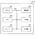
- FIG. 8 is a diagram showing an example of the hardware configuration of the base station and the user terminal according to the embodiment.
- the base station 10 and the user terminal 20 described above may be physically configured as a computer device including a processor 1001, a memory 1002, a storage 1003, a communication device 1004, an input device 1005, an output device 1006, a bus 1007, and the like. ..
- the hardware configuration of the base station 10 and the user terminal 20 may be configured to include one or more of the devices shown in the figure, or may be configured not to include some of the devices.
- processor 1001 may be a plurality of processors. Further, the processing may be executed by one processor, or the processing may be executed simultaneously, sequentially, or by using other methods by two or more processors.
- the processor 1001 may be mounted by one or more chips.
- the processor 1001 For each function of the base station 10 and the user terminal 20, for example, by loading predetermined software (program) on hardware such as the processor 1001 and the memory 1002, the processor 1001 performs an operation and communicates via the communication device 1004. It is realized by controlling at least one of reading and writing of data in the memory 1002 and the storage 1003.
- predetermined software program
- Processor 1001 operates, for example, an operating system to control the entire computer.
- the processor 1001 may be configured by a central processing unit (CPU) including an interface with peripheral devices, a control device, an arithmetic unit, a register, and the like.
- CPU central processing unit
- control unit 110 210
- transmission / reception unit 120 220
- the like may be realized by the processor 1001.
- the processor 1001 reads a program (program code), a software module, data, etc. from at least one of the storage 1003 and the communication device 1004 into the memory 1002, and executes various processes according to these.
- a program program code
- the control unit 110 may be realized by a control program stored in the memory 1002 and operating in the processor 1001, and may be realized in the same manner for other functional blocks.
- the memory 1002 is a computer-readable recording medium, for example, at least a Read Only Memory (ROM), an Erasable Programmable ROM (EPROM), an Electrically EPROM (EPROM), a Random Access Memory (RAM), or any other suitable storage medium. It may be composed of one.
- the memory 1002 may be referred to as a register, a cache, a main memory (main storage device), or the like.
- the memory 1002 can store a program (program code), a software module, or the like that can be executed to implement the wireless communication method according to the embodiment of the present disclosure.
- the storage 1003 is a computer-readable recording medium, and is, for example, a flexible disk, a floppy (registered trademark) disk, an optical magnetic disk (for example, a compact disc (Compact Disc ROM (CD-ROM)), a digital versatile disk, etc.). At least one of Blu-ray® disks, removable disks, optical disc drives, smart cards, flash memory devices (eg cards, sticks, key drives), magnetic stripes, databases, servers, and other suitable storage media. It may be composed of.
- the storage 1003 may be referred to as an auxiliary storage device.
- the communication device 1004 is hardware (transmission / reception device) for communicating between computers via at least one of a wired network and a wireless network, and is also referred to as, for example, a network device, a network controller, a network card, a communication module, or the like.
- the communication device 1004 includes, for example, a high frequency switch, a duplexer, a filter, a frequency synthesizer, etc. in order to realize at least one of frequency division duplex (Frequency Division Duplex (FDD)) and time division duplex (Time Division Duplex (TDD)). May be configured to include.
- FDD Frequency Division Duplex
- TDD Time Division Duplex
- the transmission / reception unit 120 (220), the transmission / reception antenna 130 (230), and the like described above may be realized by the communication device 1004.
- the transmission / reception unit 120 (220) may be physically or logically separated from the transmission unit 120a (220a) and the reception unit 120b (220b).
- the input device 1005 is an input device (for example, a keyboard, a mouse, a microphone, a switch, a button, a sensor, etc.) that receives an input from the outside.
- the output device 1006 is an output device (for example, a display, a speaker, a Light Emitting Diode (LED) lamp, etc.) that outputs to the outside.
- the input device 1005 and the output device 1006 may have an integrated configuration (for example, a touch panel).
- each device such as the processor 1001 and the memory 1002 is connected by the bus 1007 for communicating information.
- the bus 1007 may be configured by using a single bus, or may be configured by using a different bus for each device.
- the base station 10 and the user terminal 20 include a microprocessor, a digital signal processor (Digital Signal Processor (DSP)), an Application Specific Integrated Circuit (ASIC), a Programmable Logic Device (PLD), a Field Programmable Gate Array (FPGA), and the like. It may be configured to include hardware, and a part or all of each functional block may be realized by using the hardware. For example, processor 1001 may be implemented using at least one of these hardware.
- DSP Digital Signal Processor
- ASIC Application Specific Integrated Circuit
- PLD Programmable Logic Device
- FPGA Field Programmable Gate Array
- the terms described in the present disclosure and the terms necessary for understanding the present disclosure may be replaced with terms having the same or similar meanings.
- channels, symbols and signals may be read interchangeably.
- the signal may be a message.
- the reference signal may be abbreviated as RS, and may be referred to as a pilot, a pilot signal, or the like depending on the applied standard.
- the component carrier Component Carrier (CC)
- CC Component Carrier
- the wireless frame may be composed of one or more periods (frames) in the time domain.
- Each of the one or more periods (frames) constituting the wireless frame may be referred to as a subframe.
- the subframe may be composed of one or more slots in the time domain.
- the subframe may have a fixed time length (eg, 1 ms) that is independent of numerology.
- the numerology may be a communication parameter applied to at least one of transmission and reception of a signal or channel.
- Numerology includes, for example, subcarrier spacing (SubCarrier Spacing (SCS)), bandwidth, symbol length, cyclic prefix length, transmission time interval (Transmission Time Interval (TTI)), number of symbols per TTI, and wireless frame configuration.
- SCS subcarrier Spacing
- TTI Transmission Time Interval
- a specific filtering process performed by the transmitter / receiver in the frequency domain, a specific windowing process performed by the transmitter / receiver in the time domain, and the like may be indicated.
- the slot may be composed of one or more symbols (Orthogonal Frequency Division Multiple Access (OFDMA) symbol, Single Carrier Frequency Division Multiple Access (SC-FDMA) symbol, etc.) in the time domain.
- OFDMA Orthogonal Frequency Division Multiple Access
- SC-FDMA Single Carrier Frequency Division Multiple Access
- the slot may be a time unit based on numerology.
- the slot may include a plurality of mini slots. Each minislot may consist of one or more symbols in the time domain. The mini-slot may also be referred to as a sub-slot. A minislot may consist of a smaller number of symbols than the slot.
- a PDSCH (or PUSCH) transmitted in a time unit larger than the minislot may be referred to as a PDSCH (PUSCH) mapping type A.
- the PDSCH (or PUSCH) transmitted using the minislot may be referred to as PDSCH (PUSCH) mapping type B.
- the wireless frame, subframe, slot, minislot and symbol all represent the time unit when transmitting a signal.
- the radio frame, subframe, slot, minislot and symbol may have different names corresponding to each.
- the time units such as frames, subframes, slots, mini slots, and symbols in the present disclosure may be read as each other.
- one subframe may be called TTI
- a plurality of consecutive subframes may be called TTI
- one slot or one minislot may be called TTI. That is, at least one of the subframe and TTI may be a subframe (1 ms) in existing LTE, a period shorter than 1 ms (eg, 1-13 symbols), or a period longer than 1 ms. It may be.
- the unit representing TTI may be called a slot, a mini slot, or the like instead of a subframe.
- TTI refers to, for example, the minimum time unit of scheduling in wireless communication.
- the base station schedules each user terminal to allocate radio resources (frequency bandwidth that can be used in each user terminal, transmission power, etc.) in TTI units.
- the definition of TTI is not limited to this.
- the TTI may be a transmission time unit such as a channel-encoded data packet (transport block), a code block, or a code word, or may be a processing unit such as scheduling or link adaptation.
- the time interval for example, the number of symbols
- the transport block, code block, code word, etc. may be shorter than the TTI.
- one or more TTIs may be the minimum time unit for scheduling. Further, the number of slots (number of mini-slots) constituting the minimum time unit of the scheduling may be controlled.
- a TTI having a time length of 1 ms may be referred to as a normal TTI (TTI in 3GPP Rel. 8-12), a normal TTI, a long TTI, a normal subframe, a normal subframe, a long subframe, a slot, or the like.
- TTIs shorter than normal TTIs may be referred to as shortened TTIs, short TTIs, partial TTIs (partial or fractional TTIs), shortened subframes, short subframes, minislots, subslots, slots, and the like.
- the long TTI (for example, normal TTI, subframe, etc.) may be read as a TTI having a time length of more than 1 ms, and the short TTI (for example, shortened TTI, etc.) is less than the TTI length of the long TTI and 1 ms. It may be read as a TTI having the above TTI length.
- a resource block is a resource allocation unit in the time domain and the frequency domain, and may include one or a plurality of continuous subcarriers in the frequency domain.
- the number of subcarriers contained in the RB may be the same regardless of the numerology, and may be, for example, 12.
- the number of subcarriers contained in the RB may be determined based on numerology.
- the RB may include one or more symbols in the time domain, and may have a length of 1 slot, 1 mini slot, 1 subframe or 1 TTI.
- Each 1TTI, 1 subframe, etc. may be composed of one or a plurality of resource blocks.
- One or more RBs are a physical resource block (Physical RB (PRB)), a sub-carrier group (Sub-Carrier Group (SCG)), a resource element group (Resource Element Group (REG)), a PRB pair, and an RB. It may be called a pair or the like.
- Physical RB Physical RB (PRB)
- SCG sub-carrier Group
- REG resource element group
- the resource block may be composed of one or a plurality of resource elements (Resource Element (RE)).
- RE Resource Element
- 1RE may be a radio resource area of 1 subcarrier and 1 symbol.
- Bandwidth Part (which may also be called partial bandwidth, etc.) represents a subset of consecutive common resource blocks (RBs) for a numerology in a carrier. May be good.
- the common RB may be specified by the index of the RB with respect to the common reference point of the carrier.
- PRBs may be defined in a BWP and numbered within that BWP.
- the BWP may include UL BWP (BWP for UL) and DL BWP (BWP for DL).
- BWP UL BWP
- BWP for DL DL BWP
- One or more BWPs may be set in one carrier for the UE.
- At least one of the configured BWPs may be active, and the UE may not expect to send or receive a given channel / signal outside the active BWP.
- “cell”, “carrier” and the like in this disclosure may be read as “BWP”.
- the above-mentioned structures such as wireless frames, subframes, slots, mini slots, and symbols are merely examples.
- the number of subframes contained in a wireless frame the number of slots per subframe or wireless frame, the number of minislots contained within a slot, the number of symbols and RBs contained in a slot or minislot, included in the RB.
- the number of subcarriers, the number of symbols in the TTI, the symbol length, the cyclic prefix (CP) length, and other configurations can be changed in various ways.
- the information, parameters, etc. described in the present disclosure may be expressed using absolute values, relative values from predetermined values, or using other corresponding information. It may be represented. For example, radio resources may be indicated by a given index.
- the information, signals, etc. described in this disclosure may be represented using any of a variety of different techniques.
- data, instructions, commands, information, signals, bits, symbols, chips, etc. that may be referred to throughout the above description are voltages, currents, electromagnetic waves, magnetic fields or magnetic particles, light fields or photons, or any of these. It may be represented by a combination of.
- information, signals, etc. can be output from the upper layer to the lower layer and from the lower layer to at least one of the upper layers.
- Information, signals, etc. may be input / output via a plurality of network nodes.
- Input / output information, signals, etc. may be stored in a specific location (for example, memory) or may be managed using a management table. Input / output information, signals, etc. can be overwritten, updated, or added. The output information, signals, etc. may be deleted. The input information, signals, etc. may be transmitted to other devices.
- the notification of information is not limited to the mode / embodiment described in the present disclosure, and may be performed by using other methods.
- the notification of information in the present disclosure includes physical layer signaling (for example, downlink control information (DCI)), uplink control information (Uplink Control Information (UCI))), and higher layer signaling (for example, Radio Resource Control). (RRC) signaling, broadcast information (Master Information Block (MIB), System Information Block (SIB), etc.), Medium Access Control (MAC) signaling), other signals or combinations thereof May be carried out by.
- DCI downlink control information
- UCI Uplink Control Information
- RRC Radio Resource Control
- MIB Master Information Block
- SIB System Information Block
- MAC Medium Access Control
- the physical layer signaling may be referred to as Layer 1 / Layer 2 (L1 / L2) control information (L1 / L2 control signal), L1 control information (L1 control signal), and the like.
- the RRC signaling may be called an RRC message, and may be, for example, an RRC connection setup (RRC Connection Setup) message, an RRC connection reconfiguration (RRC Connection Reconfiguration) message, or the like.
- MAC signaling may be notified using, for example, a MAC control element (MAC Control Element (CE)).
- CE MAC Control Element
- the notification of predetermined information is not limited to the explicit notification, but implicitly (for example, by not notifying the predetermined information or another information). May be done (by notification of).
- the determination may be made by a value represented by 1 bit (0 or 1), or by a boolean value represented by true or false. , May be done by numerical comparison (eg, comparison with a given value).
- Software whether referred to as software, firmware, middleware, microcode, hardware description language, or by any other name, is an instruction, instruction set, code, code segment, program code, program, subprogram, software module.
- Applications, software applications, software packages, routines, subroutines, objects, executable files, execution threads, procedures, features, etc. should be broadly interpreted.
- software, instructions, information, etc. may be transmitted and received via a transmission medium.
- a transmission medium For example, a website where software uses at least one of wired technology (coaxial cable, fiber optic cable, twisted pair, digital subscriber line (DSL), etc.) and wireless technology (infrared, microwave, etc.).
- wired technology coaxial cable, fiber optic cable, twisted pair, digital subscriber line (DSL), etc.
- wireless technology infrared, microwave, etc.
- the terms “system” and “network” used in this disclosure may be used interchangeably.
- the “network” may mean a device (eg, a base station) included in the network.
- precoding "precoding weight”
- QCL Quality of Co-Co-Location
- TCI state Transmission Configuration Indication state
- space "Spatial relation”, “spatial domain filter”, “transmission power”, “phase rotation”, "antenna port”, “antenna port group”, “layer”, “number of layers”
- Terms such as “rank”, “resource”, “resource set”, “resource group”, “beam”, “beam width”, “beam angle”, "antenna”, “antenna element", “panel” are compatible.
- Base station BS
- radio base station fixed station
- NodeB NodeB
- eNB eNodeB
- gNB gNodeB
- Access point "Transmission point (Transmission Point (TP))
- RP Reception point
- TRP Transmission / Reception Point
- Panel , "Cell”, “sector”, “cell group”, “carrier”, “component carrier” and the like
- Base stations are sometimes referred to by terms such as macrocells, small cells, femtocells, and picocells.
- the base station can accommodate one or more (for example, three) cells.
- a base station accommodates multiple cells, the entire coverage area of the base station can be divided into multiple smaller areas, each smaller area being a base station subsystem (eg, a small indoor base station (Remote Radio)).
- Communication services can also be provided by Head (RRH))).
- RRH Head
- the term "cell” or “sector” refers to part or all of the coverage area of at least one of the base stations and base station subsystems that provide communication services in this coverage.
- MS mobile station
- UE user equipment
- terminal terminal
- Mobile stations include subscriber stations, mobile units, subscriber units, wireless units, remote units, mobile devices, wireless devices, wireless communication devices, remote devices, mobile subscriber stations, access terminals, mobile terminals, wireless terminals, remote terminals. , Handset, user agent, mobile client, client or some other suitable term.
- At least one of the base station and the mobile station may be called a transmitting device, a receiving device, a wireless communication device, or the like.
- At least one of the base station and the mobile station may be a device mounted on the mobile body, the mobile body itself, or the like.
- the moving body may be a vehicle (for example, a car, an airplane, etc.), an unmanned moving body (for example, a drone, an autonomous vehicle, etc.), or a robot (manned or unmanned type). ) May be.
- at least one of the base station and the mobile station includes a device that does not necessarily move during communication operation.
- at least one of the base station and the mobile station may be an Internet of Things (IoT) device such as a sensor.
- IoT Internet of Things
- the base station in the present disclosure may be read by the user terminal.
- communication between a base station and a user terminal has been replaced with communication between a plurality of user terminals (for example, it may be called Device-to-Device (D2D), Vehicle-to-Everything (V2X), etc.).
- D2D Device-to-Device
- V2X Vehicle-to-Everything
- Each aspect / embodiment of the present disclosure may be applied to the configuration.
- the user terminal 20 may have the function of the base station 10 described above.
- words such as "up” and “down” may be read as words corresponding to communication between terminals (for example, "side”).
- the upstream channel, the downstream channel, and the like may be read as a side channel.
- the user terminal in the present disclosure may be read as a base station.
- the base station 10 may have the functions of the user terminal 20 described above.
- the operation performed by the base station may be performed by its upper node (upper node) in some cases.
- various operations performed for communication with a terminal are performed by the base station and one or more network nodes other than the base station (for example,).
- Mobility Management Entity (MME), Serving-Gateway (S-GW), etc. can be considered, but it is not limited to these), or it is clear that it can be performed by a combination thereof.
- each aspect / embodiment described in the present disclosure may be used alone, in combination, or switched with execution. Further, the order of the processing procedures, sequences, flowcharts, etc. of each aspect / embodiment described in the present disclosure may be changed as long as there is no contradiction. For example, the methods described in the present disclosure present elements of various steps using exemplary order, and are not limited to the particular order presented.
- LTE Long Term Evolution
- LTE-A LTE-Advanced
- SUPER 3G IMT-Advanced
- 4G 4th generation mobile communication system
- 5G 5th generation mobile communication system
- 6G 6th generation mobile communication system
- xG xG (xG (x is, for example, integer, fraction)
- Future Radio Access FAA
- RAT New -Radio Access Technology
- NR New Radio
- NX New radio access
- FX Future generation radio access
- GSM registered trademark
- CDMA2000 Code Division Multiple Access
- UMB Ultra Mobile Broadband
- LTE 802.11 Wi-Fi®
- LTE 802.16 WiMAX®
- LTE 802.20 Ultra-WideBand (UWB), Bluetooth®, and other suitable radios. It may be applied to a system using a communication method, a next-generation system extended based on these, and the like.
- UMB Ultra-WideBand
- references to elements using designations such as “first” and “second” as used in this disclosure does not generally limit the quantity or order of those elements. These designations can be used in the present disclosure as a convenient way to distinguish between two or more elements. Thus, references to the first and second elements do not mean that only two elements can be adopted or that the first element must somehow precede the second element.
- determining used in this disclosure may include a wide variety of actions.
- judgment (decision) means judgment (judging), calculation (calculating), calculation (computing), processing (processing), derivation (deriving), investigation (investigating), search (looking up, search, inquiry) ( For example, searching in a table, database or another data structure), ascertaining, etc. may be considered to be "judgment”.
- judgment (decision) includes receiving (for example, receiving information), transmitting (for example, transmitting information), input (input), output (output), and access (for example). It may be regarded as “judgment (decision)" of "accessing” (for example, accessing data in memory).
- judgment (decision) is regarded as “judgment (decision)” of solving, selecting, selecting, establishing, comparing, and the like. May be good. That is, “judgment (decision)” may be regarded as “judgment (decision)” of some action.
- connection are any direct or indirect connection or connection between two or more elements. Means, and can include the presence of one or more intermediate elements between two elements that are “connected” or “joined” to each other.
- the connection or connection between the elements may be physical, logical, or a combination thereof. For example, "connection” may be read as "access”.
- the radio frequency region when two elements are connected, one or more wires, cables, printed electrical connections, etc. are used, and as some non-limiting and non-comprehensive examples, the radio frequency region, microwaves. It can be considered to be “connected” or “coupled” to each other using electromagnetic energy having wavelengths in the region, light (both visible and invisible) regions, and the like.
- the term "A and B are different” may mean “A and B are different from each other”.
- the term may mean that "A and B are different from C”.
- Terms such as “separate” and “combined” may be interpreted in the same way as “different”.
Landscapes
- Engineering & Computer Science (AREA)
- Computer Networks & Wireless Communication (AREA)
- Signal Processing (AREA)
- Physics & Mathematics (AREA)
- Mathematical Physics (AREA)
- Mobile Radio Communication Systems (AREA)
Priority Applications (4)
| Application Number | Priority Date | Filing Date | Title |
|---|---|---|---|
| PCT/JP2021/000837 WO2022153395A1 (ja) | 2021-01-13 | 2021-01-13 | 端末、無線通信方法及び基地局 |
| EP21919291.1A EP4280643A1 (en) | 2021-01-13 | 2021-01-13 | Terminal, wireless communication method, and base station |
| CN202180095355.1A CN117063503A (zh) | 2021-01-13 | 2021-01-13 | 终端、无线通信方法以及基站 |
| JP2022574912A JPWO2022153395A1 (zh) | 2021-01-13 | 2021-01-13 |
Applications Claiming Priority (1)
| Application Number | Priority Date | Filing Date | Title |
|---|---|---|---|
| PCT/JP2021/000837 WO2022153395A1 (ja) | 2021-01-13 | 2021-01-13 | 端末、無線通信方法及び基地局 |
Publications (1)
| Publication Number | Publication Date |
|---|---|
| WO2022153395A1 true WO2022153395A1 (ja) | 2022-07-21 |
Family
ID=82447019
Family Applications (1)
| Application Number | Title | Priority Date | Filing Date |
|---|---|---|---|
| PCT/JP2021/000837 WO2022153395A1 (ja) | 2021-01-13 | 2021-01-13 | 端末、無線通信方法及び基地局 |
Country Status (4)
| Country | Link |
|---|---|
| EP (1) | EP4280643A1 (zh) |
| JP (1) | JPWO2022153395A1 (zh) |
| CN (1) | CN117063503A (zh) |
| WO (1) | WO2022153395A1 (zh) |
Cited By (4)
| Publication number | Priority date | Publication date | Assignee | Title |
|---|---|---|---|---|
| WO2023170904A1 (ja) * | 2022-03-11 | 2023-09-14 | 株式会社Nttドコモ | 端末、無線通信方法及び基地局 |
| WO2023170905A1 (ja) * | 2022-03-11 | 2023-09-14 | 株式会社Nttドコモ | 端末、無線通信方法及び基地局 |
| WO2024026724A1 (en) * | 2022-08-03 | 2024-02-08 | Lenovo (Beijing) Ltd. | Support of srs transmission with 8 antenna ports |
| WO2024061093A1 (zh) * | 2022-09-24 | 2024-03-28 | 华为技术有限公司 | 一种上行预编码的指示方法及通信装置 |
Citations (1)
| Publication number | Priority date | Publication date | Assignee | Title |
|---|---|---|---|---|
| US20200412421A1 (en) * | 2018-03-13 | 2020-12-31 | Zte Corporation | Transmissions using antenna port sets |
-
2021
- 2021-01-13 WO PCT/JP2021/000837 patent/WO2022153395A1/ja active Application Filing
- 2021-01-13 CN CN202180095355.1A patent/CN117063503A/zh active Pending
- 2021-01-13 JP JP2022574912A patent/JPWO2022153395A1/ja active Pending
- 2021-01-13 EP EP21919291.1A patent/EP4280643A1/en active Pending
Patent Citations (1)
| Publication number | Priority date | Publication date | Assignee | Title |
|---|---|---|---|---|
| US20200412421A1 (en) * | 2018-03-13 | 2020-12-31 | Zte Corporation | Transmissions using antenna port sets |
Non-Patent Citations (3)
| Title |
|---|
| "Evolved Universal Terrestrial Radio Access (E-UTRA) and Evolved Universal Terrestrial Radio Access Network (E-UTRAN); Overall description; Stage 2 (Release 8", 3GPP TS 36.300 V8.12.0, April 2010 (2010-04-01) |
| CATT: "Remaining issues on non-codebook based UL transmission", 3GPP DRAFT; R1-1806277, 3RD GENERATION PARTNERSHIP PROJECT (3GPP), MOBILE COMPETENCE CENTRE ; 650, ROUTE DES LUCIOLES ; F-06921 SOPHIA-ANTIPOLIS CEDEX ; FRANCE, vol. RAN WG1, no. Busan, Korea; 20180521 - 20180525, 20 May 2018 (2018-05-20), Mobile Competence Centre ; 650, route des Lucioles ; F-06921 Sophia-Antipolis Cedex ; France , XP051441484 * |
| LENOVO ET AL.: "Discussion of multi- TRP/panel transmission", 3GPP TSG RAN WG1#98, 30 August 2019 (2019-08-30), XP051765328, Retrieved from the Internet <URL:https://www.3gpp.org/ftp/tsg_ran/WG1_RL1/TSGR1_98/Docs/Rl-1908720.zip> [retrieved on 20210706] * |
Cited By (4)
| Publication number | Priority date | Publication date | Assignee | Title |
|---|---|---|---|---|
| WO2023170904A1 (ja) * | 2022-03-11 | 2023-09-14 | 株式会社Nttドコモ | 端末、無線通信方法及び基地局 |
| WO2023170905A1 (ja) * | 2022-03-11 | 2023-09-14 | 株式会社Nttドコモ | 端末、無線通信方法及び基地局 |
| WO2024026724A1 (en) * | 2022-08-03 | 2024-02-08 | Lenovo (Beijing) Ltd. | Support of srs transmission with 8 antenna ports |
| WO2024061093A1 (zh) * | 2022-09-24 | 2024-03-28 | 华为技术有限公司 | 一种上行预编码的指示方法及通信装置 |
Also Published As
| Publication number | Publication date |
|---|---|
| EP4280643A1 (en) | 2023-11-22 |
| CN117063503A (zh) | 2023-11-14 |
| JPWO2022153395A1 (zh) | 2022-07-21 |
Similar Documents
| Publication | Publication Date | Title |
|---|---|---|
| WO2021024494A1 (ja) | 端末及び無線通信方法 | |
| WO2021090403A1 (ja) | 端末及び無線通信方法 | |
| WO2022153395A1 (ja) | 端末、無線通信方法及び基地局 | |
| WO2021005764A1 (ja) | 端末及び無線通信方法 | |
| WO2021064962A1 (ja) | 端末及び無線通信方法 | |
| WO2021002018A1 (ja) | 端末及び無線通信方法 | |
| WO2022029933A1 (ja) | 端末、無線通信方法及び基地局 | |
| WO2020209281A1 (ja) | ユーザ端末及び無線通信方法 | |
| WO2020250399A1 (ja) | 端末及び無線通信方法 | |
| WO2021117193A1 (ja) | 端末及び無線通信方法 | |
| WO2021009916A1 (ja) | 端末及び無線通信方法 | |
| WO2020202517A1 (ja) | ユーザ端末及び無線通信方法 | |
| WO2021215379A1 (ja) | 端末、無線通信方法及び基地局 | |
| WO2022029979A1 (ja) | 端末、無線通信方法及び基地局 | |
| JPWO2020090061A1 (ja) | 端末、無線通信方法、基地局及びシステム | |
| WO2021220411A1 (ja) | 端末、無線通信方法及び基地局 | |
| WO2021166036A1 (ja) | 端末、無線通信方法及び基地局 | |
| WO2021070392A1 (ja) | 端末及び無線通信方法 | |
| WO2020250400A1 (ja) | 端末及び無線通信方法 | |
| WO2020183721A1 (ja) | ユーザ端末及び無線通信方法 | |
| WO2021241210A1 (ja) | 端末、無線通信方法及び基地局 | |
| WO2022029934A1 (ja) | 端末、無線通信方法及び基地局 | |
| WO2022044290A1 (ja) | 端末、無線通信方法及び基地局 | |
| WO2021171565A1 (ja) | 端末、無線通信方法及び基地局 | |
| WO2021161451A1 (ja) | 端末、無線通信方法及び基地局 |
Legal Events
| Date | Code | Title | Description |
|---|---|---|---|
| 121 | Ep: the epo has been informed by wipo that ep was designated in this application |
Ref document number: 21919291 Country of ref document: EP Kind code of ref document: A1 |
|
| ENP | Entry into the national phase |
Ref document number: 2022574912 Country of ref document: JP Kind code of ref document: A |
|
| NENP | Non-entry into the national phase |
Ref country code: DE |
|
| ENP | Entry into the national phase |
Ref document number: 2021919291 Country of ref document: EP Effective date: 20230814 |
|
| WWE | Wipo information: entry into national phase |
Ref document number: 202180095355.1 Country of ref document: CN |