WO2022149573A1 - 観測装置および観測方法 - Google Patents
観測装置および観測方法 Download PDFInfo
- Publication number
- WO2022149573A1 WO2022149573A1 PCT/JP2022/000062 JP2022000062W WO2022149573A1 WO 2022149573 A1 WO2022149573 A1 WO 2022149573A1 JP 2022000062 W JP2022000062 W JP 2022000062W WO 2022149573 A1 WO2022149573 A1 WO 2022149573A1
- Authority
- WO
- WIPO (PCT)
- Prior art keywords
- unit
- rotating body
- rotation
- position deviation
- storage
- Prior art date
- Legal status (The legal status is an assumption and is not a legal conclusion. Google has not performed a legal analysis and makes no representation as to the accuracy of the status listed.)
- Ceased
Links
Images





Classifications
-
- G—PHYSICS
- G05—CONTROLLING; REGULATING
- G05B—CONTROL OR REGULATING SYSTEMS IN GENERAL; FUNCTIONAL ELEMENTS OF SUCH SYSTEMS; MONITORING OR TESTING ARRANGEMENTS FOR SUCH SYSTEMS OR ELEMENTS
- G05B19/00—Program-control systems
- G05B19/02—Program-control systems electric
- G05B19/18—Numerical control [NC], i.e. automatically operating machines, in particular machine tools, e.g. in a manufacturing environment, so as to execute positioning, movement or co-ordinated operations by means of program data in numerical form
- G05B19/402—Numerical control [NC], i.e. automatically operating machines, in particular machine tools, e.g. in a manufacturing environment, so as to execute positioning, movement or co-ordinated operations by means of program data in numerical form characterised by control arrangements for positioning, e.g. centring a tool relative to a hole in the workpiece, additional detection means to correct position
-
- G—PHYSICS
- G01—MEASURING; TESTING
- G01M—TESTING STATIC OR DYNAMIC BALANCE OF MACHINES OR STRUCTURES; TESTING OF STRUCTURES OR APPARATUS, NOT OTHERWISE PROVIDED FOR
- G01M1/00—Testing static or dynamic balance of machines or structures
- G01M1/14—Determining imbalance
- G01M1/16—Determining imbalance by oscillating or rotating the body to be tested
-
- B—PERFORMING OPERATIONS; TRANSPORTING
- B23—MACHINE TOOLS; METAL-WORKING NOT OTHERWISE PROVIDED FOR
- B23Q—DETAILS, COMPONENTS, OR ACCESSORIES FOR MACHINE TOOLS, e.g. ARRANGEMENTS FOR COPYING OR CONTROLLING; MACHINE TOOLS IN GENERAL CHARACTERISED BY THE CONSTRUCTION OF PARTICULAR DETAILS OR COMPONENTS; COMBINATIONS OR ASSOCIATIONS OF METAL-WORKING MACHINES, NOT DIRECTED TO A PARTICULAR RESULT
- B23Q17/00—Arrangements for observing, indicating or measuring on machine tools
- B23Q17/22—Arrangements for observing, indicating or measuring on machine tools for indicating or measuring existing or desired position of tool or work
-
- G—PHYSICS
- G01—MEASURING; TESTING
- G01M—TESTING STATIC OR DYNAMIC BALANCE OF MACHINES OR STRUCTURES; TESTING OF STRUCTURES OR APPARATUS, NOT OTHERWISE PROVIDED FOR
- G01M1/00—Testing static or dynamic balance of machines or structures
- G01M1/14—Determining imbalance
- G01M1/16—Determining imbalance by oscillating or rotating the body to be tested
- G01M1/24—Performing balancing on elastic shafts, e.g. for crankshafts
-
- G—PHYSICS
- G01—MEASURING; TESTING
- G01M—TESTING STATIC OR DYNAMIC BALANCE OF MACHINES OR STRUCTURES; TESTING OF STRUCTURES OR APPARATUS, NOT OTHERWISE PROVIDED FOR
- G01M1/00—Testing static or dynamic balance of machines or structures
- G01M1/30—Compensating imbalance
- G01M1/32—Compensating imbalance by adding material to the body to be tested, e.g. by correcting-weights
-
- B—PERFORMING OPERATIONS; TRANSPORTING
- B23—MACHINE TOOLS; METAL-WORKING NOT OTHERWISE PROVIDED FOR
- B23Q—DETAILS, COMPONENTS, OR ACCESSORIES FOR MACHINE TOOLS, e.g. ARRANGEMENTS FOR COPYING OR CONTROLLING; MACHINE TOOLS IN GENERAL CHARACTERISED BY THE CONSTRUCTION OF PARTICULAR DETAILS OR COMPONENTS; COMBINATIONS OR ASSOCIATIONS OF METAL-WORKING MACHINES, NOT DIRECTED TO A PARTICULAR RESULT
- B23Q17/00—Arrangements for observing, indicating or measuring on machine tools
-
- G—PHYSICS
- G05—CONTROLLING; REGULATING
- G05B—CONTROL OR REGULATING SYSTEMS IN GENERAL; FUNCTIONAL ELEMENTS OF SUCH SYSTEMS; MONITORING OR TESTING ARRANGEMENTS FOR SUCH SYSTEMS OR ELEMENTS
- G05B2219/00—Program-control systems
- G05B2219/30—Nc systems
- G05B2219/39—Robotics, robotics to robotics hand
- G05B2219/39101—Cooperation with one or more rotating workpiece holders, manipulators
Definitions
- the present invention relates to an observation device and an observation method for observing the balanced state of a rotating body of a machine tool.
- the field balancer is a device for observing the balance state of rotation of an observation target driven by rotation.
- the observation target is, for example, a motor (motor shaft).
- the machine tool is equipped with a rotating body that is driven to rotate.
- the rotating body is, for example, a spindle or a face plate.
- the machine tool operator attaches a field balancer to the machine tool to measure the balance of the rotating body.
- the operator can perform work for correcting the balance state of the rotating body based on the measured balance state of the rotating body.
- the accuracy of observing the balance state of the rotating body by the field balancer depends on the mounting method of the field balancer and the mounting position of the field balancer. Therefore, it is difficult for anyone to check the balance state of the rotating body with stable accuracy. It is also difficult for anyone to carry out balance correction work with stable accuracy.
- the present invention aims to solve the above-mentioned problems.
- a first aspect of the present invention is a work comprising a rotating body, a detector for detecting the rotation angle of the rotating body, and a moving body moving along a moving axis orthogonal to the rotation center line of the rotating body.
- An observation device for observing the balanced state of the rotating body of the machine, the command output unit for issuing a command to the machine tool to stop the moving body at a predetermined position while rotating the rotating body, and the above.
- a first acquisition unit that acquires the rotation angle based on the detection signal of the detector, a second acquisition unit that acquires the position deviation of the moving body in the direction of the moving axis, and an operator with respect to the rotating body.
- the robot actually changes the operation position for attaching / detaching the weight from a predetermined operation position predetermined as the operation position for attaching / detaching the weight for balance adjustment, the rotation between the predetermined operation position and the changed operation position.
- the first storage control unit that stores the first angle difference in the rotation direction of the body in the storage unit, the plurality of rotation angles, and the position deviation corresponding to each of the plurality of rotation angles are associated with each other.
- the second storage control unit to be stored in the storage unit, the rotation angle associated with the position deviation, or the current rotation angle of the rotating body is corrected based on the first angle difference.
- a graph showing the correspondence between the plurality of rotation angles and the position deviation stored in association with the plurality of rotation angles is displayed on the display unit. It is provided with a display control unit for displaying and further displaying the current rotation angle of the rotating body on the graph.
- a second aspect of the present invention is a work comprising a rotating body, a detector for detecting the rotation angle of the rotating body, and a moving body moving along a moving axis orthogonal to the rotation center line of the rotating body.
- the robot actually changes the operation position for attaching / detaching the weight from a predetermined operation position predetermined as the operation position for attaching / detaching the weight for balance adjustment, the rotation between the predetermined operation position and the changed operation position.
- the storage in which the first storage step for storing the first angle difference in the rotation direction of the body in the storage unit, the plurality of rotation angles, and the position deviation corresponding to each of the plurality of rotation angles are associated with each other.
- a graph showing the correspondence between the plurality of rotation angles and the position deviations stored in association with the plurality of rotation angles based on the correction result performed in the first correction step is displayed on the display unit. It includes a display control step for displaying and further displaying the current rotation angle of the rotating body on the graph.
- the balance state of the rotating body of the machine tool can be observed regardless of the field balancer.
- the balance correction work of the rotating body by the operator can be facilitated.
- FIG. 1 is a block diagram of an observation system according to an embodiment.
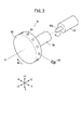
- FIG. 2 is a simplified configuration diagram of the rotating body and the spindle motor of the embodiment.
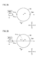
- FIG. 3A is a first schematic diagram for explaining the detection of the rotation angle by the detector.
- FIG. 3B is a second schematic diagram for explaining the detection of the rotation angle by the detector.
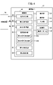
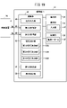
- FIG. 4 is a block diagram of the observation device of the embodiment.
- FIG. 5 is a schematic diagram illustrating the angle difference stored in the storage unit.
- FIG. 6 is a graph illustrating the phase of the rotation angle of the rotating body acquired by the first acquisition unit.
- FIG. 7 is a graph illustrating the phase of the position deviation of the moving body acquired by the second acquisition unit.
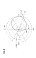
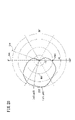
- FIG. 8 is a graph illustrating the correspondence between the plurality of rotation angles acquired by the first acquisition unit and the position deviations corresponding to each of the plurality of rotation angles acquired by the first acquisition unit.
- FIG. 9 is a diagram illustrating together the graph of FIG. 8 and the auxiliary line showing the current rotation angle corrected by the first correction unit.
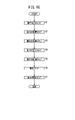
- FIG. 10 is a flowchart illustrating the flow of the observation method of the embodiment.
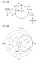
- FIG. 11A is a schematic diagram for explaining a balance correction operation in the case where the weight is attached / detached at a predetermined operation position.
- FIG. 11B is a diagram illustrating an auxiliary line and a graph displayed by the display control unit in the case of FIG. 11A.
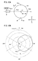
- FIG. 12A is a schematic diagram for explaining a balance correction operation when the position for attaching / detaching the weight is changed from a predetermined operation position.
- FIG. 12B is a diagram illustrating an auxiliary line and a graph displayed by the display control unit in the case of FIG. 12A.
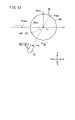
- FIG. 13 is a schematic diagram illustrating the second angle difference stored in the storage unit.
- FIG. 14 is a block diagram of the observation device of the first modification.
- FIG. 15A is a schematic diagram for explaining a balance correction operation when the first detector is not installed at a predetermined installation position and the position for attaching / detaching the weight is changed from a predetermined operation position.
- FIG. 15B is a diagram illustrating an auxiliary line and a graph displayed by the display control unit in the case of FIG.
- FIG. 16 is a schematic diagram for supplementarily explaining the application of the modified example 1.
- FIG. 17 is a configuration diagram of the observation device of the modified example 2.
- FIG. 18 is a graph of FIG. 9 in which the polarity is reversed.
- FIG. 19 is a block diagram of the observation device of the modified example 4.
- FIG. 20 is a graph of FIG. 9 in which the orientations of the deviation axes are reversed.
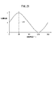
- FIG. 21 is a graph illustrating the correspondence between the plurality of rotation angles and the position deviations corresponding to each of the plurality of rotation angles.
- FIG. 1 is a block diagram of the observation system 10 of the embodiment.
- the observation system 10 has an observation device 12 and a machine tool 14. In the following, the machine tool 14 and the observation device 12 will be described in this order.
- FIG. 1 shows not only the observation system 10 but also the X-axis line and the Y-axis line.
- FIG. 2 which will be referred to later, shows a Z-axis line.
- the X-axis line, the Y-axis line, and the Z-axis line are directional axes orthogonal to each other.
- the X-axis and Z-axis are parallel to the horizontal plane.
- the Y-axis is parallel to the direction of gravity.
- one direction along the direction axis is represented by "+” and the other direction is represented by "-”.
- the direction toward one side along the X-axis line is expressed as "+ X direction”.
- the direction opposite to the + X direction is expressed as "-X direction”.
- the machine tool 14 is an industrial machine that produces a product by processing an object to be processed.
- the machine tool 14 includes a rotating body 16, a first detector 18, a moving body 20, a spindle motor 22, a feed motor 24, and a control device 26.
- the rotating body 16 is a rotating member.
- the first detector 18 is a sensor for detecting the rotation angle RA of the rotating body 16.
- the moving body 20 is a member that moves along a predetermined moving axis (moving axis).
- the spindle motor 22 is an actuator (motor) that rotates the rotating body 16.
- the feed motor 24 is an actuator (motor) that moves the moving body 20.
- the control device 26 is a device for controlling the spindle motor 22 and the feed motor 24.
- the machine tool 14 is, for example, a lathe machine. However, the machine tool 14 of the present embodiment is not limited to the lathe machine.
- FIG. 2 is a simplified configuration diagram of the rotating body 16 and the spindle motor 22 of the embodiment.
- the rotating body 16 rotates about the rotation center line LC .
- the rotation center line LC is a virtual straight line along the Z - axis direction.
- the arrow ( DR ) in FIG. 2 indicates the rotation direction of the rotating body 16.
- the rotating body 16 of the present embodiment has a spindle portion 16A and a rotating portion 16B.
- the spindle portion 16A rotates according to the drive of the spindle motor 22.
- the rotating portion 16B is a disk-shaped member.
- the rotating portion 16B is supported by the spindle portion 16A.
- the rotating portion 16B can rotate integrally with the spindle portion 16A.
- the drive system of the spindle portion 16A is an electric type. That is, the spindle portion 16A rotates in response to the drive of the electric spindle motor 22.
- the drive system of the spindle portion 16A is not limited to the electric system.
- the drive system of the spindle portion 16A may be an air system.
- the spindle portion 16A is rotationally driven according to the supplied air (air turbine).
- the spindle motor 22 may be omitted from the configuration of the machine tool 14.
- the spindle portion 16A has an end portion in the + Z direction. Its end is connected to the rotating portion 16B (see FIG. 2).
- the rotating portion 16B is, for example, a face plate or a chuck portion that supports an object to be machined.
- the rotating portion 16B has a plurality of weight attachment / detachment portions 30.
- the plurality of weight attachment / detachment portions 30 are arranged on the side surface (outer peripheral surface) of the rotating portion 16B.
- the side surface of the rotating portion 16B is a surface of the rotating portion 16B facing the X-axis direction or the Y-axis direction (see FIG. 2).
- Each of the plurality of weight attachment / detachment portions 30 holds the balance adjusting weight 28 detachably.
- the plurality of weight attachment / detachment portions 30 may be arranged on the front surface of the rotating portion 16B or on the rear surface of the rotating portion 16B.
- the front surface of the rotating portion 16B is a surface facing the + Z direction.
- the rear surface of the rotating portion 16B is a surface facing the ⁇ Z direction.
- the weight 28 is attached / detached to / from the rear surface of the rotating portion 16B.
- the weight 28 is, for example, a screw.
- each of the plurality of weight attachment / detachment portions 30 is a screw hole.
- the weight 28 is inserted into the weight attachment / detachment portion 30.
- the weight 28 is attached to the rotating portion 16B.
- the weight 28 is pulled out from the weight attachment / detachment portion 30.
- the weight 28 is removed from the rotating portion 16B.
- the weight 28 is attached to and detached from the rotating portion 16B (plural weight attachment / detachment portions 30) by an operator or a robot.
- the operation position where the work of attaching / detaching the weight 28 to / from the weight attaching / detaching portion 30 (attachment / detachment work) is performed is predetermined in the present embodiment.
- the predetermined operation position is also described as a predetermined operation position Pope .
- the predetermined operation position Pope is a position on the machine coordinate system of the machine tool 14. For example, even if the rotating portion 16B rotates along the rotation direction DR, the predetermined operation position Pop does not move.
- the predetermined operation position Pope moves together with the rotating portion 16B .
- the attachment / detachment work is performed in a state where the position of the weight attachment / detachment portion 30 is aligned with the predetermined operation position Pope in the rotation direction DR .
- the predetermined operation position Pope of the present embodiment is a position 180 degrees along the rotation direction DR from the installation position P18pre of the first detector 18.
- the predetermined operation position Pope may be the same position as the first detector 18 in the rotation direction DR .
- the spindle motor 22 that rotates the spindle portion 16A is, for example, a spindle motor.
- the spindle motor 22 has a shaft 22a.
- the shaft 22a is connected to the spindle portion 16A.
- the spindle motor 22 can rotate the spindle portion 16A along the rotation direction DR according to the rotational drive of the shaft 22a.
- the first detector 18 for detecting the rotation angle RA of the rotating body 16 is, for example, a rotary encoder.
- the first detector 18 is installed at a position different from the rotating body 16 (rotating portion 16B) on a plane parallel to the XY plane.
- FIG. 3A is a first schematic diagram for explaining the detection of the rotation angle RA by the first detector 18.
- FIG. 3B is a second schematic diagram for explaining the detection of the rotation angle RA by the first detector 18.
- the rotating portion 16B (rotating body 16) has an origin port (see FIG. 3A).
- the origin Porg is a reference point (a point indicating zero degree) of the rotation angle RA.
- the origin Porg moves along the rotation direction DR .
- the origin Porg reaches the installation position P18pre of the first detector 18 in the rotation direction DR (see FIG. 3A).
- the first detector 18 outputs a detection signal indicating zero degree as the rotation angle RA to the control device 26.
- the first detector 18 outputs a detection signal indicating ⁇ degree as the rotation angle RA to the control device 26. (See Fig. 3B).
- the installation position P 18pre of the first detector 18 is a predetermined position.
- the installation position P18pre of the present embodiment is a position in the + X direction with respect to the rotating portion 16B. Further, the installation position P 18pre of this embodiment is on the line LX .
- the line LX is a virtual straight line parallel to the X - axis line and passes through the rotation center line LC. In this case, the installation position P18pre and the above - mentioned predetermined operation position Pope sandwich the rotation center line LC on the line LX .
- the moving axis of the moving body 20 is an axis along the direction orthogonal to the rotation center line LC .
- the moving body 20 is connected to the shaft of the feed motor 24 via a ball screw and a nut.
- the ball screw is installed parallel to the moving axis of the moving body 20.
- the ball screw rotates integrally with the shaft of the feed motor 24.
- the nut is screwed into the ball screw.
- the moving body 20 is connected to the nut. As a result, the moving body 20 can move along the moving axis according to the drive of the feed motor 24.
- the illustration of the ball screw and the nut is omitted.
- the moving axis of the present embodiment is parallel to the X-axis. Therefore, the moving body 20 moves in the + X direction or the ⁇ X direction. The amount of movement of the moving body 20 correlates with the amount of rotation of the shaft of the feed motor 24.
- the moving body 20 is connected (supported) to the spindle portion 16A. As a result, the rotating body 16 moves integrally with the moving body 20 along the + X direction or the ⁇ X direction.
- the feed motor 24 that moves the moving body 20 is, for example, a servo motor.
- the feed motor 24 is provided with a second detector 32.
- the second detector 32 is a sensor for detecting the rotation angle of the feed motor 24.
- the second detector 32 is, for example, a rotary encoder.
- the control device 26 is an electronic device (computer) including, for example, a processor, a memory, and an amplifier.
- the control device 26 numerically controls the spindle motor 22 and the feed motor 24.
- the control device 26 acquires the detection signal of the first detector 18.
- the control device 26 acquires the rotation angle RA of the spindle motor 22.
- the control device 26 acquires the detection signal of the second detector 32.
- the control device 26 acquires the rotation angle of the feed motor 24.
- the control device 26 calculates the position deviation PD in the X-axis direction of the moving body 20 described below.
- the position deviation PD is a deviation (difference) between the rotation angle commanded by the control device 26 to the feed motor 24 and the actual rotation angle of the feed motor 24 in response to the command.
- the rotation amount of the feed motor 24 and the movement amount of the moving body 20 in the X-axis direction correlate with each other. Therefore, the position deviation PD substantially indicates the difference between the commanded position and the actual position of the moving body 20 in the X-axis direction.
- the control device 26 can accurately control the position of the moving body 20 in the X-axis direction by further controlling the feed motor 24 so that the position deviation PD approaches zero.
- the "rotating body 16" refers to the rotating portion 16B of the main shaft portion 16A and the rotating portion 16B.
- the observation device 12 is an electronic device for observing changes in the balance state of the rotating body 16. Although the details will be described later, the observation device 12 acquires the rotation angle RA of the rotating body 16 and the position deviation PD of the moving body 20 from the machine tool 14. Further, the observation device 12 associates the rotation angle RA and the position deviation PD with each other. In particular, the observation device 12 of the present embodiment corrects the rotation angle RA according to the change in the operation position for performing the attachment / detachment work. As a result, the observation device 12 facilitates the balance correction work of the rotating body 16 by the operator. In addition, the accuracy of balance correction is improved.
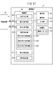
- FIG. 4 is a configuration diagram of the observation device 12 of the embodiment.
- the observation device 12 includes a display unit 34, an operation unit 36, a storage unit 38, and a calculation unit 40.
- the display unit 34 is, for example, a device having a liquid crystal screen.
- the display unit 34 displays information.
- the screen of the display unit 34 of the present embodiment is a liquid crystal screen.
- the screen of the display unit 34 is not limited to the liquid crystal screen.
- the display unit 34 may be an organic EL (OEL: Organic Electro-Luminescence) screen.
- the operation unit 36 has, for example, a keyboard, a mouse, and a touch panel.
- the touch panel is installed on the screen of the display unit 34, for example.
- the operation unit 36 receives information input by the operator. As a result, the operator can appropriately input his / her instruction to the observation device 12.
- the operation unit 36 has an input unit 47.
- the input unit 47 accepts an operation of changing the operation position of the operation unit 36 from which the operator attaches / detaches the weight 28 from the predetermined operation position Pope.
- the operator can arbitrarily change the operation position for attaching and detaching the weight 28 via the input unit 47. For example, the operator may want to place some other member in the vicinity of the predetermined operating position Pope . Here, the operator changes the operation position so that the other member does not hinder the attachment / detachment work of the weight 28.
- the operating position of the weight 28 after the change is also described as the operating position P'open .
- the operating position P'open is a position on the machine coordinate system of the machine tool 14.
- the storage unit 38 has a memory.
- the storage unit 38 has a RAM (RandomAccessMemory) and a ROM (ReadOnlyMemory).
- the storage unit 38 stores information.
- the storage unit 38 stores the observation program 42 (see FIG. 4).
- the observation program 42 is a program for causing the observation device 12 to execute the observation method of the present embodiment. A description of the observation method will be described later (FIG. 10).
- the storage unit 38 stores the first angle difference AD 1 described below.
- the first angle difference AD 1 is the angle difference between the predetermined operation position Pope and the actual operation position P'open along the rotation direction DR .
- the first angle difference AD 1 is input to the observation device 12 via the operation unit 36, for example, by an operator.
- FIG. 5 is a schematic diagram illustrating the first angle difference AD 1 stored by the storage unit 38.
- the operation position P'ope in FIG. 5 is a position of +90 degrees along the rotation direction DR from the predetermined operation position Pope .
- the first angle difference AD 1 is "90 degrees”.
- the first angle difference AD 1 90 degrees is a concrete example. Therefore, the first angle difference AD 1 is not limited to 90 degrees.
- the storage unit 38 further stores the plurality of rotation angles RA and the position deviation PD corresponding to each of the plurality of rotation angles RA.
- a description of the correspondence between the plurality of rotation angles RA and the plurality of position deviation PDs will be described later.
- the arithmetic unit 40 has a processor.
- the arithmetic unit 40 has a CPU (Central Processing Unit) and a GPU (Graphics Processing Unit).
- the calculation unit 40 includes a command output unit 44, a first acquisition unit 46, a second acquisition unit 48, a storage control unit 50, a display control unit 54, and a first correction unit 52.
- the command output unit 44 issues a command to the machine tool 14 in order to perform observation appropriately.
- the first acquisition unit 46 acquires the rotation angle RA.
- the second acquisition unit 48 acquires the position deviation PD.
- the storage control unit 50 stores information in the storage unit 38 as appropriate.
- the display control unit 54 causes the display unit 34 to display the correspondence between the rotation angle RA and the position deviation PD and the current rotation angle RA.
- the first correction unit 52 corrects the current rotation angle RA displayed on the display unit 34 based on the first angle difference AD 1 .
- the command output unit 44, the first acquisition unit 46, the second acquisition unit 48, the storage control unit 50, the display control unit 54, and the first correction unit 52 use the observation program 42 as the calculation unit 40. Is realized by executing.
- the command output unit 44 issues a command to the machine tool 14. This command includes the content of rotating the rotating body 16 and the content of stopping the moving body 20 at a predetermined position on the X-axis direction.
- the command output unit 44 issues a request to, for example, the control device 26.
- the control device 26 controls the spindle motor 22 and the feed motor 24 according to the input request.
- the command output unit 44 can easily create a situation in which it is easy to observe the position deviation PD caused by the rotation of the rotating body 16.
- the first acquisition unit 46 acquires a plurality of rotation angles RA based on the detection signal of the first detector 18.
- the first acquisition unit 46 acquires, for example, the rotation angle RA calculated by the control device 26 from the control device 26.
- the first acquisition unit 46 may acquire the detection signal from the control device 26 or the first detector 18. In that case, the first acquisition unit 46 may calculate the rotation angle RA based on the acquired detection signal.
- the acquisition cycle of the plurality of rotation angles RA by the first acquisition unit 46 is as short as possible.
- the acquisition cycle of the rotation angle RA is short, the balance state of the rotating body 16 is accurately observed.
- the acquisition cycle of the rotation angle RA is limited according to the detection cycle of the first detector 18 and the resolution of the first detector 18.
- FIG. 6 is a graph illustrating the phase of the rotation angle RA of the rotating body 16 acquired by the first acquisition unit 46.
- the graph of FIG. 6 has a vertical axis showing the rotation angle RA and a horizontal axis showing the time.
- the graph of FIG. 6 shows a plurality of rotation angles RA acquired along the time series.
- the rotation angle RA of the rotating body 16 at the time point t1 is " ⁇ 1".
- the graph of FIG. 6 can be created based on the plurality of rotation angles RA acquired by the first acquisition unit 46.
- the range of the vertical axis in FIG. 6 is 0 degrees to 360 degrees. However, the range of the vertical axis in FIG. 6 is not limited to 0 degrees to 360 degrees.
- the vertical axis of FIG. 6 may include a rotation angle RA of 361 degrees or more.
- the vertical axis including the rotation angle RA of 361 degrees or more is used, for example, when the first detector 18 can detect the rotation angle RA of 361 degrees or more.
- the second acquisition unit 48 acquires the position deviation PD.
- the second acquisition unit 48 acquires, for example, the position deviation PD calculated by the control device 26 from the control device 26.
- the second acquisition unit 48 may acquire the control command of the feed motor 24 and the detection signal of the second detector 32. In that case, the second acquisition unit 48 may calculate the position deviation PD based on the acquired control command and the detection signal.
- the acquisition cycle of the plurality of position deviation PDs by the second acquisition unit 48 is synchronized with the acquisition cycle of the plurality of rotation angles RA by the first acquisition unit 46.
- the acquisition cycle of the plurality of position deviation PDs by the second acquisition unit 48 does not have to be synchronized with the acquisition cycle of the plurality of rotation angles RA by the first acquisition unit 46.
- FIG. 7 is a graph illustrating the phase of the position deviation PD of the moving body 20 acquired by the second acquisition unit 48.
- the graph of FIG. 7 has a vertical axis showing the position deviation PD and a horizontal axis showing the time.
- the graph of FIG. 7 shows a plurality of position deviation PDs acquired along the time series.
- the position deviation PD at time point t1 is pd1.
- the time point t1 in FIG. 7 and the time point t1 in FIG. 6 are simultaneous points.
- the graph of FIG. 7 can be created based on the acquisition results of a plurality of position deviation PDs by the second acquisition unit 48.
- the memory control unit 50 has a first memory control unit 50A and a second memory control unit 50B (see FIG. 4).
- the first storage control unit 50A stores the first angle difference AD 1 in the storage unit 38.
- the first storage control unit 50A stores the first angle difference AD 1 input by the operator via the input unit 47 in the storage unit 38.
- the second storage control unit 50B stores each of the plurality of rotation angles RA and the position deviation PD in association with each other in the storage unit 38.
- the second storage control unit 50B associates a plurality of rotation angles RA (FIG. 6) and a plurality of position deviation PDs (FIG. 7) with each other on the time axis. For example, the second storage control unit 50B associates the rotation angle ⁇ 1 acquired at the time point t1 with the position deviation pd1 also acquired at the time point t1 (see FIGS. 6 and 7). Further, the second storage control unit 50B stores the rotation angle RA and the position deviation PD associated with each other in the storage unit 38.
- the acquisition cycle of the first acquisition unit 46 and the acquisition cycle of the second acquisition unit 48 may not be synchronized. In that case, there is a possibility that the rotation angle RA and the position deviation PD acquired at the same time do not exist.
- the second storage control unit 50B may associate the rotation angle RA and the position deviation PD whose acquisition time points are close to each other on the time axis. Further, the second storage control unit 50B may interpolate (estimate) the position deviation PD corresponding to the time point when the rotation angle RA is acquired, for example, by using linear interpolation (linear interpolation).
- the position deviation PD representing the balance state of the rotating body 16 at a certain rotation angle RA is detected after the rotation angle RA is detected.
- the rotation angle RA and the position deviation PD are associated with each other in consideration of the above time difference. However, in order to simplify the explanation as much as possible, the above time difference is ignored in the present embodiment.
- FIG. 8 is a graph illustrating the correspondence between the plurality of rotation angle RAs acquired by the first acquisition unit 46 and the position deviation PD corresponding to each of the plurality of rotation angle RAs acquired by the first acquisition unit 46. Is.
- the graph of FIG. 8 has an angle axis (angle axis) A RA and a deviation axis (deviation axis) A PD .
- the angle axis A RA represents the magnitude of the rotation angle RA when the position deviation PD is set to zero as a circle.
- the deviation axis A PD represents the size of the position deviation PD by the normal of the circle.
- the graph of FIG. 8 can be created based on the result of associating a plurality of rotation angles RA with a plurality of position deviation PDs.
- the display range of the rotation angle RA included in the angle axis A RA is 0 degrees to 360 degrees. That is, the display range of the rotation angle RA included in the angle axis ARA is one rotation of the rotating body 16.
- the graph of FIG. 8 includes a plurality of angular axes ARA (circles) having different diameters from each other. However, the number of the angle axis ARA may be singular.
- the position deviation PD in the + X direction is plotted outside the reference circle.
- the position deviation PD in the + X direction is larger in the + X direction as it is plotted farther from the reference circle.
- the position deviation PD in the -X direction is plotted inward of the reference circle.
- the position deviation PD in the ⁇ X direction is larger in the ⁇ X direction as it is plotted farther from the reference circle.
- the graph of FIG. 8 has a plurality of deviation axis A PDs intersecting in an asterisk pattern. However, the number of deviation axis A PDs may be singular.
- pd2 is the maximum value in the + X direction among the plurality of position deviation PDs shown in FIG.
- pd3 is the maximum value in the ⁇ X direction among the plurality of position deviation PDs shown in FIG.
- the display control unit 54 causes the display unit 34 to display a graph (see FIG. 8) showing the correspondence relationship between the plurality of rotation angles RA and the plurality of position deviation PDs associated with each of the plurality of rotation angles RA.
- the graph displayed on the display unit 34 represents the observation result of the balance state of the rotating body 16.
- the correspondence relationship shown by the graph is a correspondence relationship stored in the storage unit 38 by the second storage control unit 50B.
- the display control unit 54 further displays the auxiliary line LRA on the graph (see FIG. 8).
- the auxiliary line L RA indicates the current rotation position (rotation angle RA) of the rotating body 16.
- the operator can easily grasp the current rotation position of the rotating body 16 by referring to the auxiliary line LRA .
- the auxiliary line LRA in FIG. 8 points to ⁇ 4 degrees on the angle axis ARA . Therefore, the operator can easily grasp that the current rotation angle RA of the rotating body 16 is ⁇ 4 degrees based on the auxiliary line L RA .
- the graph of FIG. 8 is created based on the rotation angle RA and the position deviation PD.
- the rotation angle RA and the position deviation PD are numerical information that can be acquired from the machine tool 14. Therefore, the observation device 12 can observe the balanced state of the rotating body 16 without requiring a separate device such as a field balancer.
- Observation of the balanced state of the rotating body 16 by the observation device 12 can be performed if the observation device 12 and the control device 26 are communicably connected. In this case, it is not necessary to use a field balancer. Therefore, the observation result of the balance state of the rotating body 16 does not depend on the mounting method and the mounting position of the field balancer. As a result, the observation device 12 of the present embodiment can stably acquire accurate observation results.
- the first correction unit 52 corrects the current rotation angle RA (auxiliary line LRA) displayed on the display unit 34 based on the first angle difference AD 1 .
- the first angle difference AD 1 stored in the storage unit 38 is 90 degrees.
- the first correction unit 52 corrects the current rotation angle RA indicated by the auxiliary line L RA by 90 degrees along the direction opposite to the rotation direction DR.
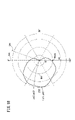
- FIG. 9 is a diagram illustrating together the graph of FIG. 8 and the auxiliary line LRA indicating the current rotation angle RA corrected by the first correction unit 52.
- the display control unit 54 described above causes the display unit 34 to display the graph and the auxiliary line LRA based on the correction result of the first correction unit 52.
- the first angle difference AD 1 is 90 degrees.
- the rotation angle RA detected by the first detector 18 is ⁇ 4 degrees.
- the auxiliary line L RA of FIG. 9 is displayed on the display unit 34.
- the auxiliary line LRA in FIG. 9 points to ⁇ 4-90 degrees. That is, the auxiliary line LRA in FIG. 9 shifts from ⁇ 4 in the direction opposite to the rotation direction DR by the first angle difference AD 1 (90 degrees).
- the corrected auxiliary line LRA indicates ⁇ 4 + 90 degrees.
- FIG. 10 is a flowchart illustrating the flow of the observation method of the embodiment.
- the observation method includes a command output step S1, a first acquisition step S2, a second acquisition step S3, a first storage step S4, a second storage step S5, and a correction step (first correction step). ) S6 and display control step S7 (see FIG. 10).
- the command output unit 44 issues a command to the machine tool 14.
- the command includes a content of rotating the rotating body 16 and a content of stopping the moving body 20 at a predetermined position.
- the command output step S1 is started, for example, when the operator gives an instruction to the observation device 12 via the operation unit 36.
- the first acquisition unit 46 acquires a plurality of rotation angles RA based on the detection signal of the first detector 18.
- the first acquisition step S2 is executed after the start of the command output step S1.
- the second acquisition unit 48 acquires a plurality of position deviation PDs.
- the second acquisition step S3 is executed after the command output step S1.
- the second acquisition step S3 is executed in parallel with the first acquisition step S2, it is time-efficient.
- the first storage control unit 50A stores the first angle difference AD 1 in the storage unit 38.
- the first storage step S4 is executed by the start of the first correction step S6 described later.
- the first storage step S4 may be executed before the command output step S1.
- the second storage control unit 50B stores the plurality of rotation angles RA and the position deviation PD corresponding to each of the plurality of rotation angles RA in the storage unit 38 in association with each other.
- the second storage step S5 is executed after the first acquisition step S2 and the second acquisition step S3.
- the first correction unit 52 corrects the current rotation angle RA based on the first angle difference AD 1 .
- the display control unit 54 causes the display unit 34 to display a graph showing the correspondence relationship between the plurality of rotation angles RA and the plurality of position deviation PDs.
- the display control step S7 is executed after the completion of both the second storage step S5 and the first correction step S6.
- the current rotation angle RA corrected in the first correction step S6 is displayed on the display unit 34 together with the graph in the display control step S7.
- the observation device 12 and the observation method contribute to the operator easily performing the balance correction work of the rotating body 16 as described below.
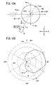
- FIG. 11A is a schematic diagram for explaining a balance correction operation in the case where the weight 28 is attached / detached at a predetermined operation position Pope .
- FIG. 11B is a diagram illustrating the graph displayed by the display control unit 54 and the auxiliary line LRA in the case of FIG. 11A.
- the predetermined operation position Pope is a position on the line LX and in the ⁇ X direction with respect to the rotating portion 16B.
- the first detector 18 is ideally installed at a predetermined installation position P18pre .
- the graph of FIG. 11B is displayed on the display unit 34.
- the rotation angle RA 90 degrees and the maximum value of the position deviation PD in the + X direction correspond to each other.
- the unbalanced position Pumb is a position (rotational position) on the rotating portion 16B.
- the unbalanced position Pumb moves along the rotation direction DR with the rotation of the rotating portion 16B.
- the time point at which the position deviation PD in the + X direction becomes maximum is the time point at which the rotation angle RA reaches 90 degrees as described above.
- the operator attaches the weight 28 to the weight attachment / detachment portion 30 at the predetermined operation position Pope along the rotation direction DR when the rotation angle RA is 90 degrees.
- the unbalanced state of the rotating body 16 of FIG. 11A is efficiently adjusted. That is, when the rotating portion 16B is in the unbalanced state, the position of the center of gravity of the rotating portion 16B shifts in the direction of the unbalanced position Pumb when viewed from the rotation center line LC . Therefore, the operator attaches the weight 28 to the weight attachment / detachment portion 30 located 180 degrees along the rotation direction DR from the unbalanced position Pumb .
- the position of the center of gravity of the rotating portion 16B efficiently approaches the position of the rotation center line LC.
- the weight attachment / detachment portion 30 located 180 degrees along the rotation direction DR from the unbalanced position Pumb has a predetermined operation position P along the rotation direction DR when the rotation angle RA is 90 degrees. It is in open .
- the weight attachment / detachment portion 30 at the predetermined operation position Pope is also referred to as a weight attachment / detachment portion 30'.
- the operator refers to the auxiliary line LRA .
- the operator adjusts the rotation angle RA of the rotating body 16 (rotating portion 16B) to 90 degrees based on the rotation angle RA indicated by the auxiliary line L RA .
- the operator attaches the weight 28 to the weight attachment / detachment portion 30'.
- the operator can suitably correct the balance state of the rotating body 16.
- the first detector 18 is installed at the installation position P18pre .
- the installation position P 18pre is on the line LX and is a position in the + X direction with respect to the rotating portion 16B.
- the rotation angle RA corresponding to the maximum value of the position deviation PD in the + X direction represents the rotation angle RA at which the unbalanced position Pumb reaches the installation position P18pre in the rotation direction DR . Therefore, the operator adjusts the rotation position of the rotating body 16 to the rotation angle RA corresponding to the maximum value of the position deviation PD in the + X direction, so that the position is 180 degrees from the predetermined operation position Pope along the rotation direction DR . It can be easily achieved to adjust the unbalanced position Pumb to. Therefore, the operator can easily correct the unbalanced state.
- the weight attachment / detachment portion 30'in FIG. 11A and the unbalanced position Pumb are at the same position with respect to the rotation direction DR. That is, the unbalanced position Pumb in FIG. 11A reaches a predetermined operation position Pope on the rotation direction DR when the rotating body 16 is further rotated by 180 degrees.
- the operator may remove the weight 28 from the weight attachment / detachment portion 30'when the rotation angle RA reaches 270 degrees. As a result, the operator can efficiently bring the position of the center of gravity closer to the rotation center line LC .
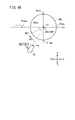
- FIG. 12A is a schematic diagram for explaining the balance correction work when the position where the weight 28 is attached / detached is changed from the predetermined operation position Pope .
- FIG. 12B is a diagram illustrating the graph displayed by the display control unit 54 and the auxiliary line LRA in the case of FIG. 12A.
- 12A and 12B are referenced for illustration purposes.
- the positional relationship between the position where the first detector 18 of FIG. 12A is installed, the origin Porg , and the unbalanced position Pumb is the same as that of the example of FIG. 11A.
- the first angle difference AD 1 occurs. That is, the actual operation position P'ope is different from the predetermined operation position P'open .
- the first angle difference AD 1 is +90 degrees.
- the rotating portion 16B is further rotated by the first angle difference AD 1 (90 degrees). There is a need.
- the current rotation angle RA indicated by the auxiliary line L RA is the rotation angle RA corrected by the amount of the first angle difference AD 1 (see FIG. 12B).
- the operator adjusts the rotation angle RA instructed by the auxiliary line L RA to the rotation angle RA corresponding to the maximum value of the position deviation PD, so that the unbalanced position Pumb is set in the rotation direction from the operation position P'ope . It can be adjusted to a position of 180 degrees along the DR .
- the operator corrects the unbalanced state of the rotating body 16 by attaching the weight 28 to the weight attachment / detachment portion 30'. Can be done.
- the observation device 12 and the observation method are provided.
- the observation device 12 executes the observation method.
- the observation device 12 observes the balance state of the rotating body 16 of the machine tool 14 regardless of the field balancer.
- the observation device 12 facilitates the balance correction work of the rotating body 16 by the operator.
- Modification 1 The embodiment has been described on the premise that the first detector 18 is installed at a predetermined installation position P18pre . However, the position where the first detector 18 is installed may be different from the installation position P18pre . Based on the above, this modification will be described below. In the following description, the position where the first detector 18 is actually installed is also described as the installation position P 18 to distinguish it from the installation position P 18 pre .
- the storage unit 38 of this modification further stores the second angle difference AD 2 .
- the second angle difference AD 2 is a phase difference between the angles of the installation position P 18pre and the installation position P 18 in the rotation direction DR .
- FIG. 13 is a schematic diagram illustrating the second angle difference AD 2 stored by the storage unit 38.
- FIG. 13 illustrates the positional relationship between the rotating portion 16B and the first detector 18.
- the first detector 18 is installed at the installation position P18.
- the installation position P 18 is a position of ⁇ 60 degrees along the rotation direction DR from the predetermined installation position P 18 pre of the first detector 18.
- the second angle difference AD 2 is ⁇ 60 degrees.
- the second angle difference AD 2 is not limited to ⁇ 60 degrees.
- the second angle difference AD 2 is stored in the storage unit 38 by the first storage control unit 50A.
- the first storage control unit 50A stores the input second angle difference AD 2 in the storage unit 38, for example, when the operator inputs the second angle difference AD 2 via the operation unit 36.
- FIG. 14 is a configuration diagram of the observation device 12 of the modified example 1.
- the observation device 12 of this modification further includes a second correction unit 56.
- the second correction unit 56 corrects the rotation angle RA corresponding to each of the plurality of position deviation PDs on the graph based on the second angle difference AD 2 .
- the second angle difference AD 2 is ⁇ 60 degrees.
- the second correction unit 56 corrects the rotation angle RA corresponding to each of the plurality of position deviation PDs by -60 degrees.
- a graph showing the correspondence between the plurality of rotation angles RA corrected based on the second angle difference AD 2 and the position deviation PD associated with each of them is displayed on the display unit 34.
- the unbalanced position Pumb in FIG. 13 is on the line LX and reaches the + X direction from the rotation center line LC when the rotation angle RA reaches 150 degrees. Therefore, in the case of FIG. 13, the rotation angle RA corresponding to the maximum value of the position deviation PD in the + X direction is 150 degrees.
- the unbalanced position Pumb is not a position 180 degrees along the rotation direction DR from the predetermined operation position Pope (see FIG. 13). Therefore, even if the operator attaches the weight 28 to the weight attachment / detachment portion 30'of the predetermined operation position Pope when the rotation angle RA is 150 degrees, does the center of gravity position of the rotation portion 16B efficiently approach the rotation center line LC ? do not have.
- the second correction unit 56 of this modification corrects each of the plurality of rotation angles RA based on the second angle difference AD 2 .
- the unbalanced position Pumb reaches the installation position P18.
- the operator adjusts the rotation angle RA to 90 degrees in the example of FIG. As a result, the unbalanced position Pumb reaches the installation position P18 . As a result, the operator can suitably perform the balance correction work even when the installation position P 18 of the first detector 18 is different from the installation position P 18pre .
- FIG. 15A is for explaining the balance correction work when the first detector 18 is not installed at the predetermined installation position P 18pre and the position where the weight 28 is attached / detached is changed from the predetermined operation position Pope . It is a schematic diagram.
- FIG. 15B is a diagram illustrating the graph displayed by the display control unit 54 and the auxiliary line LRA in the case of FIG. 15A.
- FIG. 15A the positional relationship between the origin Porg and the unbalanced position Pumb and the positional relationship between the installation position P 18pre and the installation position P 18 are the same as in FIG. 13.
- the position where the weight 28 is attached / detached is changed from the predetermined operation position Pope to the operation position P'open . Therefore, the first angle difference AD 1 occurs.
- the first angle difference AD 1 in this example is 150 degrees.
- the first correction unit 52 corrects the rotation angle RA instructed by the auxiliary line L RA based on the first angle difference AD 1 .
- the second correction unit 56 corrects the rotation angle corresponding to each of the plurality of position deviation PDs on the graph based on the second angle difference AD 2 .
- the correction of the rotation angle RA (second correction step) by the second correction unit 56 is performed in parallel with the display of the graph by the display control unit 54 in, for example, the display control step S7.
- the rotation angle RA corresponding to the maximum value of the position deviation PD is corrected from 150 degrees to 90 degrees (150 degrees -60 degrees).
- the phase (solid line) shifted by -60 degrees along the rotation direction DR from before the correction (two-dot chain line) is displayed.
- the auxiliary line L RA indicates 0 degrees (150 degrees-150 degrees), for example, when the actual rotation angle RA of the rotating body 16 is 150 degrees. Therefore, the auxiliary line L RA indicates 90 degrees (240 degrees-150 degrees) when the actual rotation angle RA of the rotating body 16 is 240 degrees.
- the time when the actual rotation angle RA of the rotating body 16 is 240 degrees is the time when the unbalanced position Pumb reaches the position of 180 degrees along the rotation direction DR from the operation position P'open in FIG. 15A.
- the operator can perform the balance correction work even when the installation position P 18 of the first detector 18 is different from the installation position P 18pre and the operation position P'ope is different from the predetermined operation position Pope . Can be preferably performed.
- FIG. 16 is a schematic diagram for supplementarily explaining the application of the modified example 1.
- the second correction unit 56 does not correct the rotation angle RA regardless of this modification.
- -60 degrees is generated as the second angle difference AD 2 , but this second angle difference AD 2 is ignored.
- the operator adjusts the rotation angle RA indicated by the auxiliary line L RA corrected based on the first angle difference AD 1 to 150 degrees (the actual rotation angle RA is 240 degrees).
- the unbalanced position Pumb reaches a position of 180 degrees from the operation position P'ope along the rotation direction DR .
- Modification 2 In the following, "polarity" will be described. Further, based on the explanation, the observation device 12 of this modification will be described. As in the embodiment (FIG. 1), the moving axis is parallel to the X-axis.
- the polarity is information that determines which of the two directions along the X-axis is the + X direction (first direction) or the ⁇ X direction (second direction).
- the positive and negative signs of the position deviation PD are determined according to this polarity.
- a position deviation PD that occurs in one direction along the X-axis is represented by a negative polarity if that one direction follows a polarity defined as the + X direction. That is, the negative number position deviation PD represents a deviation in the opposite direction of the + X direction.
- the position deviation PD generated in one direction along the X-axis line is represented by a positive polarity if the one direction follows a polarity defined as the ⁇ X direction. That is, the positive position deviation PD represents a deviation in the opposite direction of the ⁇ X direction.
- the control device 26 calculates the position deviation PD based on the polarity. Therefore, the control device 26 possesses information regarding the polarity. In this case, the observation device 12 can acquire information on the polarity from the control device 26.
- the polarity settings may be opposite to each other. In this case, even if the absolute direction and the absolute value of the position deviation PD are exactly the same, the positive and negative of the observation results (graphs) of the two machine tools 14 are reversed from each other.
- FIG. 17 is a configuration diagram of the observation device 12 of the modified example 2.
- the memory control unit 50 of this modification further includes a third memory control unit 50C (see FIG. 17).
- the third storage control unit 50C stores the polarities of the + X direction and the ⁇ X direction along the X axis in the storage unit 38. As a result, in this modification, the polarity of the observation device 12 is stored in the storage unit 38.
- the observation method may further include a polarity determination step in which the observation device 12 (calculation unit 40) specifies the polarity.
- the third storage control unit 50C stores the polarity specified in the polarity determination step in the storage unit 38.
- the observation method may include an operation step in which the operator specifies the polarity via the operation unit 36 instead of the polarity determination step.
- the third storage control unit 50C may store the polarity specified in the operation step in the storage unit 38.
- FIG. 18 is a graph of FIG. 9 in which the polarity is reversed.
- the display control unit 54 compares the polarity set in the machine tool 14 with the polarity stored in the storage unit 38 when displaying the graph on the display unit 34. If the polarity set in the machine tool 14 and the polarity stored in the storage unit 38 are opposite to each other, the display control unit 54 stores the polarities of the plurality of position deviation PDs to be displayed in the display unit 34 in the storage unit. Invert according to the polarity stored in 38 (see FIG. 18).
- the operator can refer to the observation results with a unified polarity even if the operator observes a plurality of machine tools 14 having different polarities as long as the same observation device 12 is used.
- "+" and "-" in FIG. 18 represent the polarities set in the observation device 12.
- the second acquisition unit 48 and the second storage control unit 50B may refer to the polarity stored in the storage unit 38 by the third storage control unit 50C.
- the second acquisition unit 48 may correct the positive or negative of the position deviation PD according to the polarity set in the observation device 12 when the position deviation PD is acquired.
- the second storage control unit 50B may correct the positive or negative of the position deviation PD according to the polarity set in the observation device 12 at the time of associating the rotation angle RA with the position deviation PD. ..
- FIG. 19 is a configuration diagram of the observation device 12 of the modified example 4.
- the memory control unit 50 of this modification further includes a fourth memory control unit 50D (see FIG. 19).
- the fourth storage control unit 50D stores the direction of the deviation axis A PD (see FIG. 9) in the storage unit 38. That is, the fourth storage control unit 50D stores the orientation of the position deviation PD indicated by the deviation axis A PD in the storage unit 38.
- the magnitude of the position deviation PD may be represented by an axis other than the deviation axis A PD .
- the fourth storage control unit 50D may store the orientation of the axis indicating the magnitude of the position deviation PD in the storage unit 38.
- the display control unit 54 compared the polarity set in the machine tool 14 with the polarity stored in the storage unit 38.
- the fourth storage control unit 50D compares the polarity set in the machine tool 14 with the polarity stored in the storage unit 38. If the polarity set in the machine tool 14 and the polarity stored in the storage unit 38 are opposite to each other, the fourth storage control unit 50D has the deviation axis A according to the polarity stored in the storage unit 38. Determine the orientation of the PD . Further, the fourth storage control unit 50D stores the determined direction of the deviation axis A PD in the storage unit 38.
- the observation method of the embodiment may further include an operation step of causing the operator to specify a large or small direction via the operation unit 36. In this case, the fourth storage control unit 50D may store the large and small orientations specified in the operation step in the storage unit 38.
- FIG. 20 is a graph of FIG. 9 in which the orientation of the deviation axis A PD is reversed.
- the display control unit 54 When displaying the graph on the display unit 34, the display control unit 54 refers to the direction of the deviation axis A PD stored in the storage unit 38. The display control unit 54 determines the position of the positive polarity and the position of the negative polarity according to the direction of the referenced deviation axis A PD (see FIG. 20).
- the display control unit 54 changes the direction of the deviation axis A PD according to the polarity set in the machine tool 14.
- the direction toward the center of the angle axis A RA is the negative electrode direction.
- the direction of the negative electrode is changed to the direction toward the outside of the angle axis ARA .
- the plus sign (+) and the minus sign (-) in FIG. 20 represent the polarities set in the machine tool 14.
- FIG. 21 is a graph illustrating the correspondence between the plurality of rotation angles RA and the position deviation PD corresponding to each of the plurality of rotation angles RA.
- the format of the graph showing the observation results is not limited to the format shown in FIG. 8 or FIG.
- the correspondence between the plurality of rotation angles RA and the plurality of position deviation PDs may be expressed using the form of the graph of FIG.
- the graph of FIG. 21 has a vertical axis indicating the position deviation PD and a horizontal axis indicating the rotation angle RA.
- the display control unit 54 may display both the graph of FIG. 9 and the graph of FIG. 21 on the display unit 34. Further, the display control unit 54 may allow the operator to select the format of the graph to be displayed on the display unit 34. In that case, the operation unit 36 may accept the selection operation by the operator.
- the method of indicating the current rotation angle RA of the rotating body 16 to the operator is not limited to displaying the auxiliary line L RA (FIG. 9).
- the display control unit 54 may display a numerical value indicating the rotation angle RA on the screen of the display unit 34.
- the display control unit 54 may display an icon moving along the circle represented by the angle axis ARA on the screen of the display unit 34.
- the predetermined installation position P 18pre of the first detector 18 is on the line LX and is a position in the + X direction with respect to the rotating portion 16B.
- the installation position P18pre is not limited to this.
- the installation position P 18pre may be on the line LX and may be a position in the ⁇ X direction with respect to the rotating portion 16B.
- the moving axis of the moving body 20 is not limited to the X - axis as long as it is a direction axis orthogonal to the rotation center line LC.
- the moving axis may be the Y axis.
- a ball screw (see embodiment) is installed parallel to the Y-axis.
- the installation position P 18pre of the first detector 18 is, for example, on a line passing through the rotation center line LC and parallel to the Y axis line, and at a position in the + Y direction or ⁇ Y direction with respect to the rotation portion 16B. ..
- the position deviation PD indicates a positional deviation of the moving body 20 in the Y-axis direction.
- the position deviation PD becomes maximum.
- the operator can correct the unbalanced state of the rotating body 16 by attaching the weight 28 at a position 180 degrees from the unbalanced position Pumb along the rotation direction DR .
- the second acquisition unit 48 acquires the position deviation PD in the Y axis direction.
- the second storage control unit 50B associates the corrected plurality of rotation angles RA with the plurality of position deviation PDs in the Y-axis direction.
- the machine tool 14 may include a moving body 20 moving in the X-axis direction and another moving body 20 moving in the Y-axis direction.
- the rotating body 16 can move in a plurality of directions.
- the machine tool 14 includes a plurality of feed motors 24 for moving the plurality of moving bodies 20.
- the second acquisition unit 48 acquires a position deviation PD in any one of the plurality of moving axis directions. ..
- the operator or the second acquisition unit 48 may select the moving axis direction in which the position deviation PD is acquired.
- the second storage control unit 50B associates the corrected plurality of rotation angles RA with the plurality of position deviation PDs in the direction of the selected moving axis.
- the display control unit 54 may output a graph showing the observation result to an external device of the observation device 12. That is, the display unit 34 for displaying the graph may be installed outside the observation device 12.
- the display unit 34 may be a display device included in the machine tool 14.
- the observation device 12 may be integrally configured with the control device 26 of the machine tool 14. As a result, the observation device 12 that also functions as the control device 26 of the machine tool 14 is provided.
- the moving body 20 may be a member that moves relative to the rotating body 16.
- the machine tool 14 in this case is, for example, a machining center.
- a tool is mounted on the spindle portion 16A of the machining center via a tool holder.
- the machining center performs cutting on the object to be machined by using a tool mounted on the spindle 16A.
- the object to be machined is supported by a table that moves relative to the spindle 18A.
- the rotating portion 16B in this case is a tool holder or a tool itself. Further, the moving body 20 in this case is a table.
- the shaft 22a of the spindle motor 22 may be at the same position as the rotation center line LC of the rotating portion 16B on a plane parallel to the XY plane.
- the first detector 18 may output a signal corresponding to the rotation of the shaft 22a.
- the observation device 12 may acquire the rotation angle of the shaft 22a as the rotation angle RA of the rotation unit 16B.
- the rotary encoder provided in the spindle motor 22 can be used as the first detector 18.
- the weight attachment / detachment portion 30 may be provided on the spindle portion 16A. In that case, the balance correction work of the rotating body 16 is performed by attaching / detaching the weight 28 to / from the weight attaching / detaching portion 30 of the main shaft portion 16A.
- the weight 28 may be an adhesive member that adheres to the rotating body 16.
- the adhesive member is, for example, an adhesive tape.
- the balance state of the rotating body 16 changes even if the adhesive tape is attached.
- the operator can easily finely adjust the balance state of the rotating body 16. Further, for the operator, the work of attaching the adhesive tape to the rotating body 16 is easier than the work of inserting the screws.
- each of the plurality of weight attachment / detachment portions 30 is a portion of the rotating body 16 to which the adhesive member can be attached.
- the moving body 20 is moved along the moving axis by using the ball screw and the feed motor 24.
- the moving body 20 may move, for example, depending on the direct power along the moving axis generated by the linear motor or the fluid bearing.
- the amount of movement of the moving body 20 in the moving axis direction can be measured by using, for example, a scale.
- the machine tool 14 provided with a linear motor or a fluid bearing as an element for moving the moving body 20 is, for example, an ultra-precision machine tool.
- the ultra-precision processing machine is a machine tool 14 that processes according to a command.
- the command resolution of the command of the ultra-precision processing machine is 10 nanometers or less.
- the first correction unit 52 may correct the rotation angle RA associated with the position deviation PD on the graph based on the first angle difference AD 1 .
- the display control unit 54 includes a graph in which the phase of the angle is shifted by the amount of the first angle difference AD 1 due to the correction of the first correction unit 52, and a detection that is not corrected by the first angle difference AD 1 .
- the current rotation angle RA with the value as it is is displayed on the display unit 34. In this case, the first correction unit 52 does not have to correct the current rotation angle RA (auxiliary line L RA ).
- the rotating body (16), the detector (18) for detecting the rotation angle (RA) of the rotating body, and the moving axis (X) orthogonal to the rotation center line ( LC ) of the rotating body move.
- An observation device (12) for observing the balanced state of the rotating body of the machine tool (14) including the moving body (20), and the moving body is stopped at a predetermined position while rotating the rotating body.
- a command output unit (44) that issues a command to the machine tool, a first acquisition unit (46) that acquires the rotation angle based on the detection signal of the detector, and the said in the direction of the moving axis.
- the first storage control unit (50A) that stores the first angle difference (AD 1 ) in the storage unit (38), the plurality of rotation angles, and the position deviation corresponding to each of the plurality of rotation angles.
- the second storage control unit (50B) associated with the storage unit and the rotation angle associated with the position deviation, or the current rotation angle (RA) of the rotating body is the first rotation angle.
- the plurality of rotation angles and the plurality of rotation angles are stored in association with each other.
- a display control unit (54) is provided, which displays a graph showing the correspondence with the position deviation on the display unit (34) and further displays the current rotation angle of the rotating body on the graph.
- This provides an observation device that can observe the balance state of the rotating body of the machine tool regardless of the field balancer and facilitate the balance correction work of the rotating body.
- the first storage control unit is of the rotating body having an installation position (P 18pre ) predetermined as a position where the detector is installed and a position (P 18 ) where the detector is actually installed.
- the second angle difference (AD 2 ) in the rotation direction is further stored in the storage unit, and the observation device corrects a plurality of the rotation angles based on the second angle difference (56). ),
- the second storage control unit corresponds to each of the plurality of rotation angles corrected by the second correction unit and the plurality of rotation angles corrected by the second correction unit.
- the plurality of rotation angles corrected by the second correction unit and the correction by the second correction unit are performed.
- the correspondence relationship with the position deviation stored in association with the plurality of rotation angles may be shown. As a result, even if the detector is not installed at a predetermined installation position, the operator can easily perform the balance correction work of the rotating body.
- the installation position and the predetermined operation position may be positions on a line ( LX ) parallel to the moving axis passing through the rotation center line of the rotating body and may be positions sandwiching the rotation center line. ..
- LX line parallel to the moving axis passing through the rotation center line of the rotating body
- the observation device further includes an input unit (47) for the operator to input the first angle difference, and the first storage control unit inputs the input first angle difference to the storage unit. You may memorize it. As a result, the operator can arbitrarily specify the changed operation position.
- the moving body can move along the moving axis in a first direction (+ X) and in a second direction ( ⁇ X) opposite to the first direction, and the observation device can move the moving body.
- a third storage control unit (50C) for storing the polarities of the first direction and the second direction in the storage unit is further provided, and the display control unit responds to the polarity stored in the storage unit.
- the position deviation may be displayed with the same polarity.
- the operator can refer to the observation results with a unified polarity even if the operator observes a plurality of machine tools having different polarities as long as the same observation device is used.
- the observation device further includes an operation unit (36) that accepts an operation for designating the polarity, and the third storage control unit may store the specified polarity in the storage unit. This allows the operator to optionally determine the polarity of the observation device.
- the moving body can move along the moving axis in a first direction (+ X) and in a second direction ( ⁇ X) opposite to the first direction.
- the position deviation generated in the first direction is displayed with a positive polarity
- the position deviation generated in the second direction is displayed with a negative polarity
- the observation device displays the magnitude of the position deviation in the graph.
- a fourth storage control unit (50D) for storing the orientation of the axis ( APD ) indicating the deviation in the storage unit is further provided, and the display control unit is in the orientation of the size stored in the storage unit. Accordingly, the position of the positive polarity and the position of the negative polarity in the graph may be determined.
- the polarity in the direction indicating the positive polarity of the polarity of the observation device is arranged on one of the axes of the graph.
- the polarity in the direction indicating the negative polarity of the polarity of the observation device is arranged on the fixed other side on the axis of the graph.
- the observation device further includes an operation unit (36) that accepts an operation for designating the large and small directions, and the fourth storage control unit may store the designated large and small directions in the storage unit. .. This allows the operator to arbitrarily determine the magnitude orientation.
- the display control unit may display the graph on the display unit and may further display the current rotation angle of the rotating body on the graph. This is convenient for the operator who performs the balance correction work.
- the graph shows an angle axis ( ARA ) representing the magnitude of the rotation angle when the position deviation is zero, and a deviation axis ( APD ) representing the magnitude of the position deviation with the normal of the circle. ) And may have.
- ARA angle axis
- APD deviation axis
- the transition of the position deviation accompanying the change of the rotation angle can be shown to the operator in an easy-to-understand manner.
- ⁇ Second invention> The rotating body (16), the detector (18) for detecting the rotation angle (RA) of the rotating body, and the moving axis (X) orthogonal to the rotation center line ( LC ) of the rotating body move. It is an observation method for observing the balanced state of the rotating body of the moving body (20) and the machine tool (14) provided with the moving body (20) so as to stop the moving body at a predetermined position while rotating the rotating body.
- the second acquisition step (S3) for acquiring the position deviation (PD) and the predetermined operation position (predetermined) as the operation position for the operator or the robot to attach / detach the weight (28) for balance adjustment to / from the rotating body.
- the first storage step (S4) for storing the angle difference (AD 1 ) in the storage unit (38), the plurality of rotation angles, and the position deviation corresponding to each of the plurality of rotation angles are associated with each other.
- the second storage step (S5) to be stored in the storage unit, the rotation angle associated with the position deviation, or the current rotation angle (RA) of the rotating body is based on the first angle difference.
- the plurality of rotation angles and the position deviation stored in association with the plurality of rotation angles are stored.
- a display control step (S7) is included, in which a graph showing the correspondence with the above is displayed on the display unit (34), and the current rotation angle (RA) of the rotating body is further displayed on the graph.
- This provides an observation method that can observe the balance state of the rotating body of the machine tool regardless of the field balancer and facilitate the balance correction work of the rotating body.
- the observation method further comprises a second correction step of correcting a plurality of the rotation angles based on the second angle difference, said second.
- the storage is associated with the plurality of rotation angles corrected in the second correction step and the position deviations corresponding to each of the plurality of rotation angles corrected in the second correction step.
- the graph stored in the unit and displayed in the display control step is associated with the plurality of rotation angles corrected in the second correction step and the plurality of rotation angles corrected in the second correction step. The correspondence with the position deviation stored in the above may be shown. As a result, even if the detector is not installed at a predetermined installation position, the operator can easily perform the balance correction work of the rotating body.
- the installation position and the predetermined operation position may be positions on a line ( LX ) parallel to the moving axis passing through the rotation center line of the rotating body and may be positions sandwiching the rotation center line. ..
- LX line parallel to the moving axis passing through the rotation center line of the rotating body
- the observation method further includes an input step for inputting the first angle difference, and in the first storage step, the input first angle difference may be stored.
- the operator can arbitrarily specify the changed operation position.
- the moving body can move along the moving axis in a first direction (+ X) and in a second direction ( ⁇ X) opposite to the first direction, and the observation method is:
- a third storage step for storing the polarities of the first direction and the second direction is further included, and in the display control step, the position deviation has a polarity corresponding to the polarity stored in the third storage step. May be displayed.
- the operator can refer to the observation results with a unified polarity even if the operator makes observations on a plurality of machine tools having different polarities.
- the observation method further includes an operation step for accepting an operation for designating the polarity, and in the third storage step, the designated polarity may be stored. This allows the operator to optionally determine the polarity.
- the moving body can move along the moving axis in a first direction (+ X) and in a second direction ( ⁇ X) opposite to the first direction.
- the position deviation generated in the first direction is displayed with a positive polarity
- the position deviation generated in the second direction is displayed with a negative polarity
- the observation method shows that the position deviation is large in the graph.
- a fourth storage step for storing the magnitude orientation of the axis ( APD ) indicating the deviation is further included, and in the display control step, the orientation in the graph is determined according to the magnitude orientation stored in the fourth storage step.
- the positive polarity position and the negative polarity position may be determined.
- the polarity in the direction indicating the positive polarity of the polarity of the observation device is arranged on one of the axes of the graph.
- the polarity in the direction indicating the negative polarity of the polarity of the observation device is arranged on the fixed other side on the axis of the graph.
- the observation method further includes an operation step for accepting an operation for designating the large and small directions, and in the fourth storage step, the designated large and small directions may be stored. This allows the operator to arbitrarily determine the magnitude orientation.
- the graph shows an angle axis ( ARA ) representing the magnitude of the rotation angle when the position deviation is zero, and a deviation axis ( APD ) representing the magnitude of the position deviation with the normal of the circle. ) And may have.
- ARA angle axis
- APD deviation axis
- RA rotation angle
Landscapes
- Physics & Mathematics (AREA)
- General Physics & Mathematics (AREA)
- Engineering & Computer Science (AREA)
- Human Computer Interaction (AREA)
- Manufacturing & Machinery (AREA)
- Automation & Control Theory (AREA)
- Mechanical Engineering (AREA)
- Numerical Control (AREA)
Abstract
Description
図1は、実施の形態の観測システム10の構成図である。
以下に、実施の形態に係る変形例が説明される。ただし、実施の形態と重複する説明は、以下の説明では可能な限り省略される。実施の形態で説明済の構成要素には、特に断らない限り、実施の形態と同一の参照符号が流用される。
実施の形態は、第1の検出器18が予め決められた設置位置P18preに設置されていることを前提に説明された。しかし、第1の検出器18が設置される位置は、設置位置P18preとは異なる位置であってもよい。以上を踏まえ、以下に本変形例が説明される。なお、以下の説明において、第1の検出器18が実際に設置される位置は、設置位置P18preとの区別のために設置位置P18とも記載される。
以下において、「極性」が説明される。また、その説明を踏まえ、本変形例の観測装置12が説明される。なお、実施の形態(図1)と同様に、移動軸線はX軸線と平行である。
変形例1に関連し、第2の取得部48と第2の記憶制御部50Bとは、第3の記憶制御部50Cが記憶部38に記憶させた極性を参照してもよい。例えば、第2の取得部48は、位置偏差PDを取得した時点で、観測装置12に設定された極性に合わせて位置偏差PDの正負を補正してもよい。また例えば、第2の記憶制御部50Bは、回転角度RAと位置偏差PDとの対応付けをする時点で、観測装置12に設定された極性に合わせて位置偏差PDの正負を補正してもよい。
変形例1、2に係る位置偏差PDの正負は、極性に応じて反転する。ただし、位置偏差PDの正負ではなく、観測結果を示すグラフの軸が、極性に応じて反転してもよい。これを踏まえ、以下に本変形例が説明される。なお、以下では、観測装置12の極性は記憶部38に予め記憶される。
図21は、複数の回転角度RAと、複数の回転角度RAの各々に対応する位置偏差PDとの対応関係を例示するグラフである。
回転体16の現在の回転角度RAをオペレータに示す方法は、補助線LRA(図9)を表示させることに限定されない。例えば、表示制御部54は、回転角度RAを示す数値を表示部34の画面に表示させてもよい。また例えば、表示制御部54は、角度軸線ARAにより表される円に沿って移動するアイコンを表示部34の画面に表示させてもよい。
実施の形態では、第1の検出器18の予め決められた設置位置P18preは線LX上であって回転部16Bよりも+X方向の位置であった。ただし、設置位置P18preはこれに限定されない。例えば、設置位置P18preは線LX上であって回転部16Bよりも-X方向の位置でもよい。
移動体20の移動軸線は、回転中心線LCと直交する方向軸であれば、X軸線に限定されない。例えば、移動軸線はY軸線でもよい。その場合は、ボールネジ(実施の形態参照)が、Y軸線に平行に設置される。この場合、第1の検出器18の設置位置P18preは、例えば回転中心線LCを通りY軸線に平行な線上であり、且つ、回転部16Bよりも+Y方向または-Y方向の位置である。移動軸線がY軸線である場合、位置偏差PDは、移動体20のY軸線方向の位置ズレを示す。この場合、アンバランス位置Punbが回転中心線LCを通りY軸線に平行な線上であって回転部16BのY方向の一方の位置に到達した場合に、位置偏差PDが最大になる。オペレータは、アンバランス位置Punbから回転方向DRに沿って180度の位置に錘28を取り付けることで、回転体16のアンバランス状態を修正することができる。
変形例8に関連し、工作機械14は、X軸線方向に移動する移動体20と、Y軸線方向に移動するもう一つの移動体20とを備えてもよい。異なる方向に移動する複数の移動体20が主軸部16Aに接続されることで、回転体16は複数の方向に移動可能となる。その場合、工作機械14は、複数の移動体20を移動させる複数の送りモータ24を備える。
表示制御部54は、観測結果を示すグラフを観測装置12の外部機器に出力してもよい。つまり、グラフを表示する表示部34は、観測装置12の外部に設置されてもよい。例えば、表示部34は、工作機械14が備える表示機器であってもよい。
観測装置12は、工作機械14の制御装置26と一体的に構成されてもよい。これにより、工作機械14の制御装置26としても機能する観測装置12が提供される。
移動体20は、回転体16に対して相対移動する部材でもよい。この場合の工作機械14とは、例えばマシニングセンタである。マシニングセンタの主軸部16Aには、工具ホルダを介して工具が装着される。マシニングセンタは、主軸部16Aに装着された工具を用いて、加工対象物に切削加工を施す。加工対象物は、主軸18Aに対して相対移動するテーブルに支持される。この場合の回転部16Bは工具ホルダ、または工具自体である。また、この場合の移動体20は、テーブルである。
主軸モータ22のシャフト22aが、XY平面と平行な面上において回転部16Bの回転中心線LCと同位置である場合がある。この場合、第1の検出器18は、シャフト22aの回転に応じた信号を出力してもよい。この場合、観測装置12は、シャフト22aの回転角度を、回転部16Bの回転角度RAとして取得してもよい。また、この場合、例えば主軸モータ22に設けられるロータリエンコーダを第1の検出器18として使用することができる。
錘着脱部30は、主軸部16Aに設けられてもよい。その場合、回転体16のバランス修正作業は、主軸部16Aの錘着脱部30に対して錘28を着脱させることにより行われる。
錘28は、回転体16に粘着する粘着部材でもよい。粘着部材は、例えば粘着テープである。回転体16のバランス状態は粘着テープを貼り付けるだけでも変動する。粘着テープを用いることで、オペレータは、回転体16のバランス状態を微細に調整しやすい。また、オペレータにしてみると、回転体16に粘着テープを貼り付ける作業は、ネジを挿入する作業よりも容易である。
実施の形態では、ボールネジと送りモータ24とを用いて移動体20を移動軸線に沿って移動させることが説明された。これに関し、移動体20は、例えばリニアモータまたは流体軸受が生じる移動軸線に沿った直動力に応じて、移動してもよい。
第1の補正部52は、グラフ上で位置偏差PDと対応付けられる回転角度RAを、第1の角度差AD1に基づいて補正してもよい。この場合、表示制御部54は、第1の補正部52の補正により第1の角度差AD1の分だけ角度の位相がシフトしたグラフと、第1の角度差AD1で補正されていない検出値そのままの現在の回転角度RAとを表示部34に表示させる。なお、この場合、第1の補正部52は、現在の回転角度RA(補助線LRA)を補正しなくてもよい。
前述の各変形例は、矛盾の生じない範囲内で適宜組み合わされてもよい。
上記実施の形態および変形例から把握しうる発明について、以下に記載する。
回転体(16)と、前記回転体の回転角度(RA)を検出する検出器(18)と、前記回転体の回転中心線(LC)と直交する移動軸(X)に沿って移動する移動体(20)と、を備える工作機械(14)の前記回転体のバランス状態を観測する観測装置(12)であって、前記回転体を回転させつつ、前記移動体を所定の位置で停止するように前記工作機械に指令を出す指令出力部(44)と、前記検出器の検出信号に基づいて前記回転角度を取得する第1の取得部(46)と、前記移動軸の方向における前記移動体の位置偏差(PD)を取得する第2の取得部(48)と、前記回転体に対してオペレータまたはロボットがバランス調整用の錘(28)を着脱する操作位置として予め決められた所定操作位置(Pope)から実際に前記錘を着脱する操作位置を変更したときの、前記所定操作位置と変更後の操作位置(P’ope)との前記回転体の回転方向(DR)における第1の角度差(AD1)を記憶部(38)に記憶させる第1の記憶制御部(50A)と、複数の前記回転角度と、複数の前記回転角度の各々に対応する前記位置偏差とを対応付けて前記記憶部に記憶させる第2の記憶制御部(50B)と、前記位置偏差に対応付けられた前記回転角度、または前記回転体の現在の回転角度(RA)を前記第1の角度差に基づいて補正する第1の補正部(52)と、前記第1の補正部の補正結果に基づいて、複数の前記回転角度と、複数の前記回転角度に対応付けられて記憶された前記位置偏差との対応関係を示すグラフを表示部(34)に表示させると共に、前記回転体の現在の回転角度をグラフ上にさらに表示させる表示制御部(54)と、を備える。
回転体(16)と、前記回転体の回転角度(RA)を検出する検出器(18)と、前記回転体の回転中心線(LC)と直交する移動軸(X)に沿って移動する移動体(20)と、を備える工作機械(14)の前記回転体のバランス状態を観測する観測方法であって、前記回転体を回転させつつ、前記移動体を所定の位置で停止するように前記工作機械に指令を出す指令出力ステップ(S1)と、前記検出器の検出信号に基づいて前記回転角度を取得する第1の取得ステップ(S2)と、前記移動軸の方向における前記移動体の位置偏差(PD)を取得する第2の取得ステップ(S3)と、前記回転体に対してオペレータまたはロボットがバランス調整用の錘(28)を着脱する操作位置として予め決められた所定操作位置(Pope)から実際に前記錘を着脱する操作位置を変更したときの、前記所定操作位置と変更後の操作位置(P’ope)との前記回転体の回転方向(DR)における第1の角度差(AD1)を記憶部(38)に記憶させる第1の記憶ステップ(S4)と、複数の前記回転角度と、複数の前記回転角度の各々に対応する前記位置偏差とを対応付けて前記記憶部に記憶させる第2の記憶ステップ(S5)と、前記位置偏差に対応付けられた前記回転角度、または前記回転体の現在の回転角度(RA)を前記第1の角度差に基づいて補正する第1の補正ステップ(S6)と、前記第1の補正ステップで行った補正結果に基づいて、複数の前記回転角度と、複数の前記回転角度に対応付けられて記憶された前記位置偏差との対応関係を示すグラフを表示部(34)に表示させると共に、前記回転体の現在の回転角度(RA)を前記グラフ上にさらに表示させる表示制御ステップ(S7)と、を含む。
Claims (18)
- 回転体(16)と、前記回転体の回転角度(RA)を検出する検出器(18)と、前記回転体の回転中心線(LC)と直交する移動軸(X)に沿って移動する移動体(20)と、を備える工作機械(14)の前記回転体のバランス状態を観測する観測装置(12)であって、
前記回転体を回転させつつ、前記移動体を所定の位置で停止するように前記工作機械に指令を出す指令出力部(44)と、
前記検出器の検出信号に基づいて前記回転角度を取得する第1の取得部(46)と、
前記移動軸の方向における前記移動体の位置偏差(PD)を取得する第2の取得部(48)と、
前記回転体に対してオペレータまたはロボットがバランス調整用の錘(28)を着脱する操作位置として予め決められた所定操作位置(Pope)から実際に前記錘を着脱する操作位置を変更したときの、前記所定操作位置と変更後の操作位置(P’ope)との前記回転体の回転方向(DR)における第1の角度差(AD1)を記憶部(38)に記憶させる第1の記憶制御部(50A)と、
複数の前記回転角度と、複数の前記回転角度の各々に対応する前記位置偏差とを対応付けて前記記憶部に記憶させる第2の記憶制御部(50B)と、
前記位置偏差に対応付けられた前記回転角度、または前記回転体の現在の回転角度(RA)を前記第1の角度差に基づいて補正する第1の補正部(52)と、
前記第1の補正部の補正結果に基づいて、複数の前記回転角度と、複数の前記回転角度に対応付けられて記憶された前記位置偏差との対応関係を示すグラフを表示部(34)に表示させると共に、前記回転体の現在の回転角度を前記グラフ上にさらに表示させる表示制御部(54)と、
を備える、観測装置。 - 請求項1に記載の観測装置であって、
前記第1の記憶制御部は、前記検出器を設置する位置として予め決められた設置位置(P18pre)と、前記検出器が実際に設置された位置(P18)との、前記回転体の回転方向における第2の角度差(AD2)をさらに前記記憶部に記憶させ、
前記観測装置は、前記第2の角度差に基づいて複数の前記回転角度を補正する第2の補正部(56)をさらに備え、
前記第2の記憶制御部は、前記第2の補正部が補正した複数の前記回転角度と、前記第2の補正部が補正した複数の前記回転角度の各々に対応する前記位置偏差とを対応付けて前記記憶部に記憶させ、
前記表示制御部が表示させる前記グラフは、前記第2の補正部が補正した複数の前記回転角度と、前記第2の補正部が補正した複数の前記回転角度に対応付けられて記憶された前記位置偏差との対応関係を示す、観測装置。 - 請求項2に記載の観測装置であって、
前記設置位置および前記所定操作位置は、前記回転体の回転中心線を通る前記移動軸と平行な線(LX)上の位置であって、前記回転中心線を挟み合う位置である、観測装置。 - 請求項1~3のいずれか1項に記載の観測装置であって、
オペレータが前記第1の角度差を入力するための入力部(47)をさらに備え、
前記第1の記憶制御部は、入力された前記第1の角度差を前記記憶部に記憶させる、観測装置。 - 請求項1~4のいずれか1項に記載の観測装置であって、
前記移動体は、前記移動軸に沿って、第1の方向(+X)と、前記第1の方向とは反対の第2の方向(-X)とに移動可能であり、
前記観測装置は、前記第1の方向および前記第2の方向の極性を前記記憶部に記憶させる第3の記憶制御部(50C)をさらに備え、
前記表示制御部は、前記記憶部に記憶された前記極性に応じた極性で前記位置偏差を表示させる、観測装置。 - 請求項5に記載の観測装置であって、
前記極性を指定する操作を受け付ける操作部(36)をさらに備え、
前記第3の記憶制御部は、指定された前記極性を前記記憶部に記憶させる、観測装置。 - 請求項1~4のいずれか1項に記載の観測装置であって、
前記移動体は、前記移動軸に沿って、第1の方向(+X)と、前記第1の方向とは反対の第2の方向(-X)とに移動可能であり、
前記グラフでは、前記第1の方向に生じた前記位置偏差は正の極性で表示され、前記第2の方向に生じた前記位置偏差は負の極性で表示され、
前記観測装置は、前記グラフで前記位置偏差の大きさを示す軸(APD)の大小の向きを前記記憶部に記憶させる第4の記憶制御部(50D)をさらに備え、
前記表示制御部は、前記記憶部に記憶された前記大小の向きに応じて、前記グラフにおける前記正の極性の位置と前記負の極性の位置とを決定する、観測装置。 - 請求項7に記載の観測装置であって、
前記大小の向きを指定する操作を受け付ける操作部(36)をさらに備え、
前記第4の記憶制御部は、指定された前記大小の向きを前記記憶部に記憶させる、観測装置。 - 請求項1~8のいずれか1項に記載の観測装置であって、
前記グラフは、前記位置偏差をゼロとした場合の前記回転角度の大きさを円で表す角度軸(ARA)と、前記位置偏差の大きさを前記円の法線で表す偏差軸(APD)とを有する、観測装置。 - 回転体(16)と、前記回転体の回転角度(RA)を検出する検出器(18)と、前記回転体の回転中心線(LC)と直交する移動軸(X)に沿って移動する移動体(20)と、を備える工作機械(14)の前記回転体のバランス状態を観測する観測方法であって、
前記回転体を回転させつつ、前記移動体を所定の位置で停止するように前記工作機械に指令を出す指令出力ステップ(S1)と、
前記検出器の検出信号に基づいて前記回転角度を取得する第1の取得ステップ(S2)と、
前記移動軸の方向における前記移動体の位置偏差(PD)を取得する第2の取得ステップ(S3)と、
前記回転体に対してオペレータまたはロボットがバランス調整用の錘(28)を着脱する操作位置として予め決められた所定操作位置(Pope)から実際に前記錘を着脱する操作位置を変更したときの、前記所定操作位置と変更後の操作位置(P’ope)との前記回転体の回転方向(DR)における第1の角度差(AD1)を記憶部(38)に記憶させる第1の記憶ステップ(S4)と、
複数の前記回転角度と、複数の前記回転角度の各々に対応する前記位置偏差とを対応付けて前記記憶部に記憶させる第2の記憶ステップ(S5)と、
前記位置偏差に対応付けられた前記回転角度、または前記回転体の現在の回転角度(RA)を前記第1の角度差に基づいて補正する第1の補正ステップ(S6)と、
前記第1の補正ステップで行った補正結果に基づいて、複数の前記回転角度と、複数の前記回転角度に対応付けられて記憶された前記位置偏差との対応関係を示すグラフを表示部(34)に表示させると共に、前記回転体の現在の回転角度を前記グラフ上にさらに表示させる表示制御ステップ(S7)と、
を含む、観測方法。 - 請求項10に記載の観測方法であって、
前記第1の記憶ステップでは、前記検出器を設置する位置として予め決められた設置位置(P18pre)と、前記検出器が実際に設置された位置(P18)との、前記回転体の回転方向における第2の角度差(AD2)をさらに記憶し、
前記観測方法は、前記第2の角度差に基づいて複数の前記回転角度を補正する第2の補正ステップをさらに含み、
前記第2の記憶ステップでは、前記第2の補正ステップで補正した複数の前記回転角度と、前記第2の補正ステップで補正した複数の前記回転角度の各々に対応する前記位置偏差とを対応付けて前記記憶部に記憶させ、
前記表示制御ステップで表示させる前記グラフは、前記第2の補正ステップで補正した複数の前記回転角度と、前記第2の補正ステップで補正した複数の前記回転角度に対応付けられて記憶された前記位置偏差との対応関係を示す、観測方法。 - 請求項11に記載の観測方法であって、
前記設置位置および前記所定操作位置は、前記回転体の回転中心線を通る前記移動軸と平行な線(LX)上の位置であって、前記回転中心線を挟み合う位置である、観測方法。 - 請求項10~12のいずれか1項に記載の観測方法であって、
前記第1の角度差を入力する入力ステップをさらに含み、
前記第1の記憶ステップでは、入力された前記第1の角度差を記憶する、観測方法。 - 請求項10~13のいずれか1項に記載の観測方法であって、
前記移動体は、前記移動軸に沿って、第1の方向(+X)と、前記第1の方向とは反対の第2の方向(-X)とに移動可能であり、
前記観測方法は、前記第1の方向および前記第2の方向の極性を記憶する第3の記憶ステップをさらに含み、
前記表示制御ステップでは、前記第3の記憶ステップで記憶した前記極性に応じた極性で前記位置偏差を表示させる、観測方法。 - 請求項14に記載の観測方法であって、
前記極性を指定する操作を受け付ける操作ステップをさらに含み、
前記第3の記憶ステップでは、指定された前記極性を記憶する、観測方法。 - 請求項10~13のいずれか1項に記載の観測方法であって、
前記移動体は、前記移動軸に沿って、第1の方向(+X)と、前記第1の方向とは反対の第2の方向(-X)とに移動可能であり、
前記グラフでは、前記第1の方向に生じた前記位置偏差は正の極性で表示され、前記第2の方向に生じた前記位置偏差は負の極性で表示され、
前記観測方法は、前記グラフで前記位置偏差の大きさを示す軸(APD)の大小の向きを記憶する第4の記憶ステップをさらに含み、
前記表示制御ステップでは、前記第4の記憶ステップで記憶した前記大小の向きに応じて、前記グラフにおける前記正の極性の位置と前記負の極性の位置とを決定する、観測方法。 - 請求項16に記載の観測方法であって、
前記大小の向きを指定する操作を受け付ける操作ステップをさらに含み、
前記第4の記憶ステップでは、指定された前記大小の向きを記憶する、観測方法。 - 請求項10~17のいずれか1項に記載の観測方法であって、
前記グラフは、前記位置偏差をゼロとした場合の前記回転角度の大きさを円で表す角度軸(ARA)と、前記位置偏差の大きさを前記円の法線で表す偏差軸(APD)とを有する、観測方法。
Priority Applications (4)
| Application Number | Priority Date | Filing Date | Title |
|---|---|---|---|
| US18/260,153 US20240053723A1 (en) | 2021-01-07 | 2022-01-05 | Observation device and observation method |
| DE112022000236.0T DE112022000236T5 (de) | 2021-01-07 | 2022-01-05 | Beobachtungsvorrichtung und Beobachtungsverfahren |
| CN202280008826.5A CN116802468A (zh) | 2021-01-07 | 2022-01-05 | 观测装置及观测方法 |
| JP2022574054A JPWO2022149573A1 (ja) | 2021-01-07 | 2022-01-05 |
Applications Claiming Priority (2)
| Application Number | Priority Date | Filing Date | Title |
|---|---|---|---|
| JP2021001389 | 2021-01-07 | ||
| JP2021-001389 | 2021-01-07 |
Publications (1)
| Publication Number | Publication Date |
|---|---|
| WO2022149573A1 true WO2022149573A1 (ja) | 2022-07-14 |
Family
ID=82357743
Family Applications (1)
| Application Number | Title | Priority Date | Filing Date |
|---|---|---|---|
| PCT/JP2022/000062 Ceased WO2022149573A1 (ja) | 2021-01-07 | 2022-01-05 | 観測装置および観測方法 |
Country Status (5)
| Country | Link |
|---|---|
| US (1) | US20240053723A1 (ja) |
| JP (1) | JPWO2022149573A1 (ja) |
| CN (1) | CN116802468A (ja) |
| DE (1) | DE112022000236T5 (ja) |
| WO (1) | WO2022149573A1 (ja) |
Citations (4)
| Publication number | Priority date | Publication date | Assignee | Title |
|---|---|---|---|---|
| US5544073A (en) * | 1994-06-02 | 1996-08-06 | Computational Systems, Inc. | Rotor balancing calculator |
| JPH11326105A (ja) * | 1997-12-02 | 1999-11-26 | Guzik Technical Enterp Inc | スピンスタンド及びディスク試験装置の平衡をとるための方法及び装置 |
| JP2011107028A (ja) * | 2009-11-19 | 2011-06-02 | Toyota Motor Corp | 回転軸の測定装置 |
| JP2015137875A (ja) * | 2014-01-20 | 2015-07-30 | ファナック株式会社 | 回転工具の回転振れ及び動バランス調整機構 |
Family Cites Families (6)
| Publication number | Priority date | Publication date | Assignee | Title |
|---|---|---|---|---|
| JP2716237B2 (ja) | 1990-02-27 | 1998-02-18 | ファナック株式会社 | モータのバランス構造 |
| JP4672299B2 (ja) * | 2004-07-26 | 2011-04-20 | ヤマザキマザック株式会社 | 工作機械のバランサ取付角度算出方法、及び工作機械 |
| DE102005042718A1 (de) * | 2005-09-02 | 2007-03-08 | MAPAL Fabrik für Präzisionswerkzeuge Dr. Kress KG | Werkzeug zur spanenden Bearbeitung von Werkstückoberflächen |
| JP4522493B1 (ja) * | 2010-02-19 | 2010-08-11 | 博明 山本 | バランサー |
| CN110023858B (zh) * | 2017-06-20 | 2020-01-07 | 山崎马扎克公司 | 机床管理系统以及机床的管理方法 |
| CN110799395B (zh) * | 2017-06-28 | 2021-12-03 | 弗克斯特有限公司 | 用于确定制动盘的位置偏差的方法和装置 |
-
2022
- 2022-01-05 US US18/260,153 patent/US20240053723A1/en active Pending
- 2022-01-05 CN CN202280008826.5A patent/CN116802468A/zh not_active Withdrawn
- 2022-01-05 WO PCT/JP2022/000062 patent/WO2022149573A1/ja not_active Ceased
- 2022-01-05 JP JP2022574054A patent/JPWO2022149573A1/ja not_active Withdrawn
- 2022-01-05 DE DE112022000236.0T patent/DE112022000236T5/de active Pending
Patent Citations (4)
| Publication number | Priority date | Publication date | Assignee | Title |
|---|---|---|---|---|
| US5544073A (en) * | 1994-06-02 | 1996-08-06 | Computational Systems, Inc. | Rotor balancing calculator |
| JPH11326105A (ja) * | 1997-12-02 | 1999-11-26 | Guzik Technical Enterp Inc | スピンスタンド及びディスク試験装置の平衡をとるための方法及び装置 |
| JP2011107028A (ja) * | 2009-11-19 | 2011-06-02 | Toyota Motor Corp | 回転軸の測定装置 |
| JP2015137875A (ja) * | 2014-01-20 | 2015-07-30 | ファナック株式会社 | 回転工具の回転振れ及び動バランス調整機構 |
Also Published As
| Publication number | Publication date |
|---|---|
| DE112022000236T5 (de) | 2023-09-28 |
| JPWO2022149573A1 (ja) | 2022-07-14 |
| CN116802468A (zh) | 2023-09-22 |
| US20240053723A1 (en) | 2024-02-15 |
Similar Documents
| Publication | Publication Date | Title |
|---|---|---|
| JP4276270B2 (ja) | 接触検知によるワークの基準位置設定機能を有する工作機械 | |
| JP6978456B2 (ja) | 情報処理装置および情報処理方法 | |
| CN101357443A (zh) | 具有通过接触检测来校正安装误差的功能的机床 | |
| US20140350881A1 (en) | Angle measuring device and methods for calibration | |
| CN102216860A (zh) | 用于标定工业机器人系统的方法和设备 | |
| JP2020159752A (ja) | 主軸振動測定システム、主軸振動測定方法、およびプログラム | |
| Yang et al. | Identification and compensation of 11 position-independent geometric errors on five-axis machine tools with a tilting head | |
| JP2020038569A (ja) | 数値制御方法及び数値制御装置 | |
| WO2022149572A1 (ja) | 観測装置および観測方法 | |
| KR20190085429A (ko) | 공작기계의 주축 보정장치 및 보정방법 | |
| JP2012152898A (ja) | ロボットのターゲット位置検出装置、半導体装置およびターゲット位置検出方法 | |
| WO2022149573A1 (ja) | 観測装置および観測方法 | |
| JP2023028733A (ja) | 工作機械の電流計測システムおよびその方法 | |
| JPH03217907A (ja) | 円弧補間軌跡表示機能を有する数値制御方法およびその装置 | |
| US11409258B2 (en) | Information processing device and information processing method | |
| US20070145932A1 (en) | Controller for machine tool | |
| JP7096455B1 (ja) | 観測装置および観測方法 | |
| EP1752845A1 (en) | Rotary table balance monitor | |
| EP4134762A1 (en) | Machining method | |
| JP2010029973A (ja) | 研削盤および研削方法 | |
| US20250360588A1 (en) | Machine tool, and machine tool alignment method | |
| TW202317959A (zh) | 運算裝置及運算方法 | |
| US20230364729A1 (en) | Machine tool | |
| JP7637600B2 (ja) | エアスピンドル装置 | |
| JP2008194758A (ja) | 作業補助装置、作業補助方法及びその作業に使用するワーク回転装置 |
Legal Events
| Date | Code | Title | Description |
|---|---|---|---|
| 121 | Ep: the epo has been informed by wipo that ep was designated in this application |
Ref document number: 22736741 Country of ref document: EP Kind code of ref document: A1 |
|
| ENP | Entry into the national phase |
Ref document number: 2022574054 Country of ref document: JP Kind code of ref document: A |
|
| WWE | Wipo information: entry into national phase |
Ref document number: 112022000236 Country of ref document: DE Ref document number: 202280008826.5 Country of ref document: CN Ref document number: 18260153 Country of ref document: US |
|
| 122 | Ep: pct application non-entry in european phase |
Ref document number: 22736741 Country of ref document: EP Kind code of ref document: A1 |