WO2022149571A1 - 観測装置および観測方法 - Google Patents
観測装置および観測方法 Download PDFInfo
- Publication number
- WO2022149571A1 WO2022149571A1 PCT/JP2022/000060 JP2022000060W WO2022149571A1 WO 2022149571 A1 WO2022149571 A1 WO 2022149571A1 JP 2022000060 W JP2022000060 W JP 2022000060W WO 2022149571 A1 WO2022149571 A1 WO 2022149571A1
- Authority
- WO
- WIPO (PCT)
- Prior art keywords
- spindle
- observation device
- movement information
- observation
- rotation
- Prior art date
- Legal status (The legal status is an assumption and is not a legal conclusion. Google has not performed a legal analysis and makes no representation as to the accuracy of the status listed.)
- Ceased
Links
Images






Classifications
-
- B—PERFORMING OPERATIONS; TRANSPORTING
- B23—MACHINE TOOLS; METAL-WORKING NOT OTHERWISE PROVIDED FOR
- B23Q—DETAILS, COMPONENTS, OR ACCESSORIES FOR MACHINE TOOLS, e.g. ARRANGEMENTS FOR COPYING OR CONTROLLING; MACHINE TOOLS IN GENERAL CHARACTERISED BY THE CONSTRUCTION OF PARTICULAR DETAILS OR COMPONENTS; COMBINATIONS OR ASSOCIATIONS OF METAL-WORKING MACHINES, NOT DIRECTED TO A PARTICULAR RESULT
- B23Q17/00—Arrangements for observing, indicating or measuring on machine tools
-
- G—PHYSICS
- G01—MEASURING; TESTING
- G01M—TESTING STATIC OR DYNAMIC BALANCE OF MACHINES OR STRUCTURES; TESTING OF STRUCTURES OR APPARATUS, NOT OTHERWISE PROVIDED FOR
- G01M1/00—Testing static or dynamic balance of machines or structures
- G01M1/14—Determining imbalance
- G01M1/16—Determining imbalance by oscillating or rotating the body to be tested
-
- G—PHYSICS
- G05—CONTROLLING; REGULATING
- G05B—CONTROL OR REGULATING SYSTEMS IN GENERAL; FUNCTIONAL ELEMENTS OF SUCH SYSTEMS; MONITORING OR TESTING ARRANGEMENTS FOR SUCH SYSTEMS OR ELEMENTS
- G05B19/00—Program-control systems
- G05B19/02—Program-control systems electric
- G05B19/18—Numerical control [NC], i.e. automatically operating machines, in particular machine tools, e.g. in a manufacturing environment, so as to execute positioning, movement or co-ordinated operations by means of program data in numerical form
- G05B19/406—Numerical control [NC], i.e. automatically operating machines, in particular machine tools, e.g. in a manufacturing environment, so as to execute positioning, movement or co-ordinated operations by means of program data in numerical form characterised by monitoring or safety
- G05B19/4063—Monitoring general control system
Definitions
- the present invention relates to an observation device and an observation method for observing the balanced state of the spindle of a machine tool.
- a field balancer is described in Japanese Patent Application Laid-Open No. 03-251066.
- the field balancer is a device for measuring the balance state of a measurement target driven by rotation.
- the measurement target is, for example, a motor (motor shaft).
- the operator of a machine tool uses a field balancer, for example, to measure the balance state of the spindle of the machine tool.
- the operator attaches the field balancer (accelerometer pickup sensor) to the machine tool.
- the work of attaching the field balancer to the machine tool is laborious and time-consuming.
- the accuracy of observing the balance state of the spindle by the field balancer depends on how the field balancer is attached to the machine tool and the mounting position of the field balancer. Therefore, it is difficult for anyone to check the balance state of the spindle with stable observation accuracy.
- the present invention aims to solve the above-mentioned problems.
- the first aspect of the present invention is an observation device for observing the balanced state of the spindle of a machine tool, in which the spindle and the spindle are rotatably fixed and orthogonal to the axial direction of the spindle.
- the observation device includes a first acquisition unit for acquiring the rotation angle of the rotating spindle, and a moving state of the moving body when the spindle is rotating. It includes a second acquisition unit for acquiring movement information, and an output generation unit for displaying each of the rotation angles of the spindle and the movement information on the display unit in association with each other.
- a second aspect of the present invention is an observation method for observing a balanced state of a spindle of a machine tool, in which the spindle and the spindle are rotatably fixed and orthogonal to the axial direction of the spindle.
- the observation method includes a first acquisition step of acquiring the rotation angle of the rotating spindle, and a moving state of the moving body when the spindle is rotating. It includes a second acquisition step of acquiring movement information, and an output generation step of associating each of the rotation angles of the spindle with the movement information and displaying the movement information on the display unit.
- the balance state of the spindle of the machine tool is observed regardless of the field balancer.
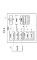
- FIG. 1 is a block diagram of an observation system according to an embodiment.
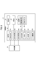
- FIG. 2 is a block diagram of the observation device of the embodiment.
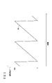
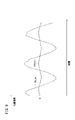
- FIG. 3 is a graph illustrating the rotation angle on the time axis of the main axis acquired by the first acquisition unit.
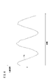
- FIG. 4 is a graph showing the phase of the position deviation of the moving body acquired by the second acquisition unit.
- FIG. 5 is a diagram illustrating the observation result of the balance state of the spindle observed by the observation device of the embodiment.
- FIG. 6 is a flowchart illustrating the flow of the observation method of the embodiment.
- FIG. 7 is a block diagram of the observation system of the modified example 4.
- FIG. 8 is a block diagram of the observation device of the modified example 5.
- FIG. 1 is a block diagram of an observation system according to an embodiment.
- FIG. 2 is a block diagram of the observation device of the embodiment.
- FIG. 3 is a graph illustrating the rotation angle on the time axis of the main axis acquired by the
- FIG. 9 is a graph illustrating the time transition of the position deviation of the moving body.
- FIG. 10 is a block diagram of the observation device of the modified example 6.
- FIG. 11 is a graph illustrating the phase on the time axis between the rotation angle of the main axis and the position deviation before and after the correction by the correction unit.
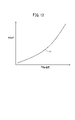
- FIG. 12 is a graph for explaining the correction amount stored in the storage unit.
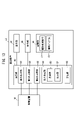
- FIG. 13 is a block diagram of the observation device of the modified example 7.
- FIG. 14 is a diagram illustrating the observation result of the balance state of the spindle observed by the observation device of the modified example 7.
- FIG. 1 is a block diagram of the observation system 10 of the embodiment.
- the observation system 10 includes a machine tool 14, a control device 16, and an observation device 12.
- the control device 16 is connected to the machine tool 14 so as to be able to control the machine tool 14.
- the control device 16 and the observation device 12 are communicably connected to each other.
- the machine tool 14 is, for example, a lathe machine.
- the machine tool 14 includes a spindle 18, a spindle motor 20, a moving body 22, and a feed shaft motor 24.
- the spindle 18 rotates about the axis A 18 (see FIG. 1).
- the spindle motor 20 is a spindle motor.
- the spindle motor 20 rotates the spindle 18.
- a drive current is supplied to the spindle motor 20.
- the spindle motor 20 is driven.
- the spindle 18 rotates according to the drive of the spindle motor 20.
- the spindle motor 20 is provided with a first detector 26.
- the first detector 26 is, for example, a rotary encoder.
- the first detector 26 outputs a signal corresponding to the rotation angle of the shaft of the spindle motor 20.
- the first detector 26 feeds back the signal to the spindle amplifier 32A.
- the spindle amplifier 32A will be described later.
- the moving body 22 moves the spindle 18 along the moving direction D 22 .
- the moving direction D 22 is a direction orthogonal to the extending direction of the axis A 18 (see FIG. 1).
- the moving body 22 is connected to the feed shaft motor 24 via a conversion mechanism (not shown).
- This conversion mechanism (not shown) is, for example, a ball screw mechanism.
- a conversion mechanism (not shown) converts the rotational force generated by the feed shaft motor 24 into direct power in the moving direction D 22 and transmits it to the moving body 22.
- the moving body 22 moves along the moving direction D 22 according to the direct power transmitted from the conversion mechanism (not shown).
- the spindle 18 is rotatably fixed (supported) to the moving body 22. Therefore, when the moving body 22 moves in the moving direction D 22 , the spindle 18 also moves in the moving direction D 22 .
- the feed shaft motor 24 is a servomotor for controlling the movement of the moving body 22.
- a drive current is supplied to the feed shaft motor 24.
- the shaft of the feed shaft motor 24 is rotationally driven.
- the feed shaft motor 24 generates the above-mentioned rotational force.
- the feed shaft motor 24 is also supplied with a drive current even when the position of the moving body 22 is maintained.
- the feed shaft motor 24 is provided with a second detector 28.
- the second detector 28 is, for example, a rotary encoder.
- the second detector 28 outputs a signal corresponding to the rotation angle of the shaft of the feed shaft motor 24.
- the second detector 28 feeds back the signal to the feed shaft amplifier 32B.
- the feed shaft amplifier 32B will be described later.
- the machine tool 14 may include a plurality of feed shaft motors 24.
- the plurality of feed shaft motors 24 may move the moving body 22 along different directions from each other.
- the feed shaft motor 24 may be a linear motor.
- the feed shaft motor 24 has a linear motion shaft.
- the second detector 28 detects the position of the linear motion shaft of the feed shaft motor 24.
- the second detector 28 that detects the position of the linear motion shaft of the feed shaft motor 24 is, for example, a linear encoder.
- the feed shaft motor 24 is a linear motor, the feed shaft motor 24 produces direct power. In that case, the above-mentioned conversion mechanism is unnecessary.
- the control device 16 is a numerical control device that feedback-controls the machine tool 14.
- the control device 16 includes a command unit (processor) 30 and an amplifier 32.
- the command unit 30 generates a control command for numerically controlling the spindle motor 20 and the feed shaft motor 24. Further, the command unit 30 outputs the generated control command to the amplifier 32.
- the command unit 30 may receive a command based on the observation control command 41 from the observation device 12 (details will be described later). In this case, the command unit 30 outputs a control command based on the observation control command 41 to the amplifier 32.
- the amplifier 32 has a spindle amplifier 32A and a feed shaft amplifier 32B.
- the spindle amplifier 32A is a drive device connected to the command unit 30 and the spindle motor 20.
- the spindle amplifier 32A supplies a drive current to the spindle motor 20 based on the control command of the command unit 30 and the rotation angle of the shaft of the spindle motor 20.
- the rotation angle of the shaft of the spindle motor 20 is calculated based on the output signal of the first detector 26.
- the feed shaft amplifier 32B is a drive device connected to the command unit 30 and the feed shaft motor 24.
- the feed shaft amplifier 32B supplies a drive current to the feed shaft motor 24 based on the control command of the command unit 30 and the rotation angle of the feed shaft motor 24.
- the rotation angle of the feed shaft motor 24 is calculated based on the output signal of the second detector 28.
- FIG. 2 is a schematic configuration diagram of the observation device 12 of the embodiment.
- the observation device 12 is an electronic device (computer) for observing the balanced state of the spindle 18. As will be described in detail below, the observation device 12 observes the balance state of the spindle 18 by associating the rotation angle of the spindle 18 with the information (movement information) indicating the motion state of the moving body 22 on the time axis. do.
- the observation device 12 acquires movement information. Specifically, the movement information is, for example, the position deviation of the moving body 22.
- the control device 16 feedback-controls the feed shaft motor 24.
- the position deviation of the moving body 22 is generally calculated in the process of feedback control. Therefore, the observation device 12 can acquire the position deviation of the moving body 22 from the control device 16.
- the movement information contains a large amount of deviation components affected by the vibration transmitted from the spindle 18. Therefore, it is preferable that the observation device 12 acquires the movement information while the control device 16 controls the feed shaft motor 24 in order to make the moving body 22 stationary.
- the observation device 12 includes a display unit 34, an operation unit 36, a storage unit 38, and a calculation unit 40.
- the display unit 34 is a display device having a screen.
- the screen is, for example, a liquid crystal screen.
- Information is displayed on the screen as appropriate. For example, the observation result of FIG. 5 is displayed on the screen.
- the operation unit 36 is an input device that accepts information input.
- the operation unit 36 has, for example, a keyboard, a mouse, and a touch panel. However, the operation unit 36 may have an operation panel.
- the touch panel is installed on the screen of the display unit 34, for example. The operator can instruct the observation device 12 to start observing the balanced state, for example, via the operation unit 36.
- the storage unit 38 has a memory for storing information.
- the storage unit 38 has, for example, a RAM (RandomAccessMemory) and a ROM (ReadOnlyMemory).
- the storage unit 38 stores the observation control command 41 and the predetermined observation program 42.
- the observation control command 41 is information including the content of the command for instructing the control device 16.
- the observation control command 41 includes a command for rotating the spindle 18. Further, it is preferable that the observation control command 41 further includes a command for maintaining the position of the moving body 22 at a predetermined position.
- the observation program 42 is a program for causing the observation device 12 to execute the observation method of the present embodiment. The details of the observation method will be described later.
- the calculation unit 40 has a processor that processes information by calculation.
- the arithmetic unit 40 has, for example, a CPU (Central Processing Unit) and a GPU (Graphics Processing Unit).
- the calculation unit 40 includes a command output unit 43, a first acquisition unit 44, a second acquisition unit 46, and an output generation unit 48.
- Each of the command output unit 43, the first acquisition unit 44, the second acquisition unit 46, and the output generation unit 48 is realized by the arithmetic unit 40 executing the observation program 42.
- the command output unit 43 outputs a command including at least the observation control command 41 to the control device 16.
- the control device 16 controls the spindle motor 20 in order to rotate the spindle 18.
- the control device 16 may gradually increase the rotational speed of the shaft of the spindle motor 20 at a constant acceleration.
- the control device 16 may gradually increase the rotational speed of the shaft of the spindle motor 20.
- the control device 16 controls the feed shaft motor 24 in order to maintain the position of the moving body 22 at a predetermined position. For example, when the position of the moving body 22 deviates from a predetermined position, the control device 16 moves the moving body 22 to a predetermined position.
- the first acquisition unit 44 acquires the rotation angle of the spindle 18.
- the rotation angle of the spindle 18 and the rotation angle of the shaft of the spindle motor 20 match.
- the control device 16 calculates the rotation angle of the shaft of the spindle motor 20 in order to feedback control the spindle motor 20. Therefore, the first acquisition unit 44 may acquire the rotation angle of the shaft of the spindle motor 20 from the control device 16. As a result, the first acquisition unit 44 substantially acquires the rotation angle of the spindle 18.
- the storage unit 38 stores the acquired rotation angle of the spindle 18.
- FIG. 3 is a graph illustrating the rotation angle of the spindle 18 acquired by the first acquisition unit 44 on the time axis.
- the graph illustrated in FIG. 3 shows the phase (RA) of the rotation angle of the spindle 18.
- the graph of FIG. 3 has a vertical axis indicating a rotation angle and a horizontal axis indicating time.
- the range of the rotation angle is 0 degrees to 360 degrees (one rotation of the spindle 18).
- the range of the rotation angle is not limited to this.
- the second acquisition unit 46 acquires movement information from the control device 16.
- the control device 16 controls the feed shaft motor 24 in order to make the moving body 22 rest at a predetermined position. Therefore, the movement information contains many deviation components affected by the vibration transmitted from the spindle 18.
- FIG. 4 is a graph illustrating the position deviation on the time axis acquired by the second acquisition unit 46.
- the graph illustrated in FIG. 4 shows the phase of the position deviation (Pd) of the moving body 22.
- the graph of FIG. 4 has a vertical axis indicating a position deviation and a horizontal axis indicating time.
- the position deviation of the moving body 22 fluctuates according to the vibration of the moving body 22. This vibration is transmitted from the main shaft 18 to the moving body 22. That is, the spindle 18 vibrates when it rotates.
- the vibration amount of the spindle 18 changes according to the balance state of the spindle 18. Therefore, the transition of the position deviation indirectly indicates the change of the balance state of the spindle 18.
- the output generation unit 48 generates an observation result (FIG. 5) based on the rotation angle of the spindle 18 and the movement information (positional deviation of the moving body 22). Further, the output generation unit 48 outputs the generated observation result to the display unit 34. More specifically, the output generation unit 48 includes a generation unit 50 and an output unit 52.
- FIG. 5 is a diagram illustrating the observation result of the balance state of the spindle 18 observed by the observation device 12 of the embodiment.
- the generation unit 50 associates the rotation angle of the main shaft 18 (FIG. 3) with the position deviation of the moving body 22 (FIG. 4) on the time axis. That is, the rotation angle and the position deviation detected at the same time are associated with each other. As a result, the generation unit 50 generates the observation result (FIG. 5).
- the transition of the position deviation (Pd) accompanying the rotation of the spindle 18 is displayed in polar coordinate format.
- the distance from the origin indicates the magnitude of the position deviation.
- Pd0 is a reference value of the position deviation. That is, at Pd0, the position deviation is zero.
- the output unit 52 outputs the observation result generated by the generation unit 50 to the display unit 34.
- the operator observes the displayed observation results.
- the operator can grasp the change in the position deviation of the moving body 22 due to the rotation of the main shaft 18. That is, the operator can easily grasp the change in the balance state of the rotating spindle 18.
- FIG. 6 is a flowchart illustrating the flow of the observation method of the embodiment.
- the observation method of the present embodiment includes a command output step (S1), a first acquisition step (S2), a second acquisition step (S3), a determination step (S4), and an output generation step (S5). And, including.
- the observation device 12 executes the command output step.
- the command output step the command output unit 43 outputs a command to the control device 16.
- This command includes the content of the observation control command 41.
- the spindle 18 starts rotating. Further, the position of the moving body 22 is maintained at a predetermined position.
- the observation device 12 executes the first acquisition step and the second acquisition step. The first acquisition step and the second acquisition step may be executed in parallel with each other.
- the first acquisition unit 44 acquires the rotation angle of the spindle 18 that rotates based on the command.
- the storage unit 38 stores the acquired rotation angle of the spindle 18.
- the second acquisition unit 46 acquires the movement information (positional deviation of the moving body 22) during the rotation of the spindle 18.
- the storage unit 38 stores the acquired movement information.
- the moving body 22 vibrates according to the rotation of the spindle 18. Therefore, the position deviation acquired by the second acquisition unit 46 includes a large amount of deviation components corresponding to the vibration of the spindle 18.
- the determination step it is determined whether or not the calculation unit 40 has acquired the rotation angle for one rotation of the spindle 18 and the position deviation corresponding to one rotation of the spindle 18. This determination is made based on the information stored in the storage unit 38.
- the observation device 12 has the first acquisition step. Repeat the second acquisition step.
- the observation device 12 starts the subsequent steps. ..
- the output generation step includes a generation step (S51) and an output step (S52).
- the generation step the generation unit 50 generates an observation result (FIG. 5) of the balance state of the spindle 18.
- the observation result is generated by associating each rotation angle of the spindle 18 with the position deviation.
- the output unit 52 outputs the observation result generated in the generation step to the display unit 34. As a result, the operator can observe the balance state of the spindle 18 via the display unit 34.
- the field balancer has a problem that the observation accuracy of the balanced state is unstable. That is, the accuracy of observing the balance state by the field balancer depends on the mounting method of the field balancer and the mounting position. On the other hand, the observation device 12 observes the balance state based on the information acquired from the control device 16. Therefore, the accuracy of observing the balanced state by the observing device 12 is more stable than when the field balancer is used.
- the observation device 12 may be included in the control device 16. Thereby, for example, the display unit 34, the operation unit 36, the storage unit 38, and the calculation unit 40 are realized by the hardware of the control device 16.
- the observation device 12 may start generating observation results before completing the acquisition of the rotation angle for one rotation of the spindle 18 and the position deviation of the moving body 22 corresponding to one rotation of the spindle 18. ..
- the observation device 12 may sequentially draw the observation results on the display unit 34 as the rotation angle of the main shaft 18 is acquired and the position deviation of the moving body 22 is acquired.
- the observation device 12 associates the first rotation angle of the spindle 18 with the first position deviation of the moving body 22.
- the observation device 12 outputs the first rotation angle and the first position deviation to the display unit 34.
- the observation device 12 associates the second rotation angle of the spindle 18 with the second position deviation of the moving body 22.
- the observation device 12 outputs the second rotation angle and the second position deviation to the display unit 34.
- the machine tool 14 is not limited to a lathe machine as long as it includes a rotating member (spindle 18) and a member (moving body 22) that moves (vibrates) in response to the vibration of the rotating member.
- the spindle 18 may be an air spindle that rotates according to the supplied air.
- FIG. 7 is a configuration diagram of the observation system 10 of the modified example 4.
- the spindle 18 in FIG. 7 is an air spindle.
- the machine tool 14 of FIG. 7 includes a third detector 54 and an air turbine 55.
- the third detector 54 is a sensor for detecting the rotation angle of the spindle 18.
- the first acquisition unit 44 acquires the rotation angle of the spindle 18 based on the detection result of the third detector 54.
- the air turbine 55 is a turbine for rotating the main shaft 18.
- the third detector 54 in FIG. 7 is connected to the observation device 12. In this case, the third detector 54 inputs a signal corresponding to the rotation of the spindle 18 to the observation device 12. However, the third detector 54 may input a signal corresponding to the rotation of the spindle 18 to the control device 16. In that case, the observation device 12 may acquire the signal of the third detector 54 via the control device 16.
- the field balancer is not required even in this modification.
- the responsiveness of the feedback control of the feed shaft motor 24 changes according to the gain.
- Typical examples of gains include position loop gains, current loop gains, and velocity loop gains.
- the machining accuracy of the machine tool 14 increases as the gain is increased. Therefore, in the general control of the machine tool 14, the gain is optimized to be as high as possible.
- the state in which the gain is optimized in order to perform machining with high accuracy is described as a high gain state or a high gain. Further, a state in which at least one of the position loop gain, the current loop gain, and the speed loop gain is lower than the set value of the high gain is described as a low gain state or a low gain. Based on the above, the observation device 12 of this modification will be described below.
- FIG. 8 is a configuration diagram of the observation device 12 of the modified example 5.
- the second acquisition unit 46 acquires movement information while the feed shaft motor 24 is controlled by low gain.
- the observation device 12 of this modification further includes a gain adjusting unit 56.
- the gain adjusting unit 56 requests the control device 16 (command unit 30) to control the feed shaft motor 24 with a low gain.
- the gain adjusting unit 56 requires the control device 16 to lower the position loop gain.
- the control device 16 lowers the position loop gain based on the request.
- the gain adjusting unit 56 may request the control device 16 to lower the current loop gain or the speed loop gain.
- FIG. 9 is a graph illustrating the time transition of the position deviation of the moving body 22. Note that FIG. 9 illustrates the position deviation when the feed shaft motor 24 is controlled by high gain and the position deviation when the feed shaft motor 24 is controlled by low gain.
- the two-dot chain line Pd High shows the phase of the position deviation acquired at high gain.
- the broken line Pd Low shows the phase of the position deviation acquired at low gain.
- the control responsiveness of the feed shaft motor 24 is lower than in the case of high gain. Therefore, the position deviation in the case of low gain is more likely to fluctuate than the position deviation in the case of high gain.
- the gain adjusting unit 56 requires the control device 16 to control the feed shaft motor 24 with a low gain. As a result, the second acquisition unit 46 can easily acquire the position deviation that more strongly reflects the balance state of the spindle 18.
- the gain adjusting unit 56 may return the gain setting to the original (high gain) when the balance state is not observed (when the observation is completed).
- the moving body 22 and the spindle 18 are separate members from each other. Therefore, there is a time lag between the vibration of the spindle 18 and the transmission of the vibration to the moving body 22. Depending on the time lag, the temporal phase of the positional deviation of the moving body 22 is delayed from the temporal phase of the rotation angle of the spindle 18.
- the specifics will be described below.
- the rotation angle of the spindle 18 at time t is ⁇ (t).
- the time lag is t'.
- the rotation angle of the spindle 18 at time t + t' is ⁇ (t + t').
- the position deviation of the moving body 22 at time t + t' is Pd (t + t').
- the vibration generated in the spindle 18 at time t is transmitted to the moving body 22 at time t + t'.
- the position deviation Pd (t + t') reflects the balance state of the spindle 18 at the rotation angle ⁇ (t).
- the position deviation Pd (t + t') does not reflect the balance state of the spindle 18 at the rotation angle ⁇ (t + t').
- the above-mentioned time lag is a minute time. Therefore, even if the time lag is ignored, the reliability of the observation results will not be significantly reduced. However, in order to improve the observation accuracy as much as possible, it is more preferable to consider the time lag.
- FIG. 10 is a configuration diagram of the observation device 12 of the modified example 6.
- the observation device 12 of this modification further includes a correction unit 58.
- the correction unit 58 corrects the rotation angle of the spindle 18 based on the correction amount C.
- the correction amount C is a time amount representing the above-mentioned time lag.
- FIG. 11 is a graph illustrating the phase on the time axis between the rotation angle of the main shaft 18 and the position deviation before and after the correction by the correction unit 58.
- FIG. 11 shows a one-dot chain line (Pd'), a broken line (Pd), and a solid line (RA).
- the alternate long and short dash line (Pd') indicates the temporal phase of the positional deviation of the moving body 22 before correction.
- the broken line (Pd) indicates the temporal phase of the position deviation of the moving body 22 after correction.
- the solid line (RA) indicates the temporal phase of the rotation angle of the spindle 18 (similar to FIG. 3).
- the correction unit 58 advances the temporal phase of the position deviation (Pd') by the amount of correction amount C.
- the generation unit 50 can accurately associate the rotation angle (RA) of the main shaft 18 with the position deviation (Pd') of the moving body 22.
- the generation unit 50 can associate the rotation angle ⁇ (t) with the position deviation Pd (t + t').
- the time lag changes according to the rotation speed of the spindle 18. Therefore, it is desirable to change the correction amount C according to the rotation speed of the spindle 18.
- the correction amount C for each rotation speed of the spindle 18 is obtained based on an experiment.
- the experiment is performed, for example, as follows. First, the experimenter intentionally puts the spindle 18 in an unbalanced state. The experimenter can put the spindle 18 in an unbalanced state by attaching a weight (lead) to the spindle 18. Next, the experimenter observes the position deviation of the moving body 22 while rotating the spindle 18 at a specific rotation speed. Since the spindle 18 is in an unbalanced state, the positional deviation of the moving body 22 differs depending on the rotation angle of the spindle 18.
- the experimenter can predict the rotation angle of the spindle 18 corresponding to the maximum value of the position deviation of the moving body 22 based on the unbalanced angle (mounting position of the weight) of the spindle 18.
- the rotation angle of the spindle 18 at the time when the position deviation of the moving body 22 becomes maximum is different from the rotation angle predicted by the experimenter. Therefore, based on this angle difference, the experimenter can back-calculate the time lag (correction amount C) corresponding to the specific rotation speed of the spindle 18.
- FIG. 12 is a graph for explaining the correction amount C stored in the storage unit 38.
- FIG. 12 illustrates a solid line TL.
- the solid line TL indicates a change in the time lag (correction amount C) according to the rotation speed of the spindle 18.
- the correspondence between the rotation speed of the spindle 18 and the time lag (correction amount C) is stored by the storage unit 38.
- the correction unit 58 uses the correction amount C properly according to the rotation speed of the spindle 18 by referring to the storage unit 38. As a result, the correction unit 58 can accurately correct the rotation angle of the spindle 18.
- the plurality of correction amounts C can be obtained by performing the above-mentioned experiment a plurality of times while changing the rotation speed of the spindle 18.
- the obtained plurality of correction amounts C can also be represented in the same graph as in FIG. 12 (however, the vertical axis represents the correction amount C).
- the above-mentioned time lag differs depending not only on the rotation speed of the spindle 18 but also on the load (mass) of the spindle 18. Therefore, the plurality of correction amounts C may be obtained according to the load of the spindle 18. Further, for example, some of the plurality of correction quantities C that can be represented in the graph as shown in FIG. 12 may be obtained by interpolation (linear interpolation) based on some other correction quantities C that have already been obtained. The specifics are described below.
- a third correction amount is shown in the figure based on the first correction amount and the second correction amount. It may be interpolated into 12 graphs. In this case, the interpolation is, for example, linear interpolation.
- the observation result of FIG. 5 is generated based on the numerical value acquired from the control device 16. Here, it is easier for the operator to see the line (Pd) showing the transition of the position deviation shown in FIG. 5 if it is as smooth as possible.
- FIG. 13 is a configuration diagram of the observation device 12 of the modified example 7.
- the observation device 12 of this modification further includes a calculation unit 60.
- the calculation unit 60 obtains the average value of a plurality of position deviations for each of the plurality of angle sections.
- the angle section is a section divided by a predetermined angle width among the rotation angles (0 degrees to 360 degrees) for one rotation of the main shaft 18.
- the predetermined angular width is, for example, 5 degrees.
- the rotation angle for one rotation of the spindle 18 includes 72 angle sections (for example, a section of 0 degrees to 5 degrees, a section of 6 degrees to 10 degrees, ).
- the angle width is not limited to 5 degrees and may be changed as appropriate.
- the calculation unit 60 refers to the result of associating the rotation angle of the spindle 18 with the position deviation of the moving body 22 performed by the generation unit 50. Since this correspondence has already been described in the embodiment, the description in this modification is omitted.
- the calculation unit 60 calculates the average value of a plurality of position deviations corresponding to the plurality of rotation angles included in the angle section for each angle section.
- the generation unit 50 re-associates the rotation angle of the main shaft 18 with the position deviation of the moving body 22 based on the average value calculated by the calculation unit 60.
- the generation unit 50 associates a plurality of rotation angles included in the angle section with the average value calculated for the angle section for each angle section.
- FIG. 14 is a diagram illustrating the observation result of the balance state of the spindle 18 observed by the observation device 12 of the modified example 7.
- FIG. 14 shows the transition of the position deviation accompanying the rotation of the spindle 18 more smoothly than in FIG. Therefore, it becomes easy for the operator to observe the tendency of the change of the balance state of the spindle 18.
- the above-mentioned calculation unit 60 may obtain the average value of a plurality of position deviations corresponding to each of the rotation angles of the spindle 18. That is, by rotating the spindle 18 a plurality of times, the second acquisition unit 46 can acquire a plurality of position deviations corresponding to the same rotation angle. In this case, the calculation unit 60 may obtain the average value of the plurality of position deviations.
- the above-mentioned calculation unit 60 may obtain a moving average of a plurality of position deviations during one rotation of the spindle 18.
- the observation device 12 acquires the position deviation (pd 1 , pd 2 , ..., Pd n ) for n rotations with respect to a certain rotation angle ⁇ .
- the calculation unit 60 may obtain the moving average value of the n position deviations.
- the generation unit 50 may associate the rotation angle ⁇ with the moving average values of n position deviations (pd 1 , pd 2 , ..., Pdn). Note that n is a natural number.
- the movement information is not limited to the position deviation of the moving body 22.
- the observation device 12 may acquire, for example, the drive position, drive current, speed, speed deviation, acceleration, acceleration deviation, jerk, or jerk deviation of the feed shaft motor 24 as movement information.
- the drive position, drive current, velocity, velocity deviation, acceleration, acceleration deviation, jerk, and jerk deviation are information generally handled in the feedback control of the feed shaft motor 24. Therefore, the observation device 12 can acquire the drive position, drive current, velocity, velocity deviation, acceleration, acceleration deviation, jerk, or jerk deviation from the control device 16 in the same manner as the position deviation.
- the observation result exemplified in FIG. 5 or FIG. 14 includes the speed deviation of the feed shaft motor 24 for each rotation angle instead of the position deviation.
- the output unit 52 may output the observation result to an external device of the observation device 12.
- the external device is, for example, a control device 16. That is, the display unit 34 to which the output unit 52 outputs the observation result may be provided in the external device of the observation device 12.
- the external device may have an operation interface (input device).
- the observation device 12 may be operated via the operation interface of the external device.
- the operation unit 36 may be omitted from the configuration of the observation device 12 if it is not necessary.
- the observation device includes a moving body (22) that moves in the direction (D 22 ), and the observation device has a first acquisition unit (44) that acquires a rotation angle of the rotating spindle, and the spindle is rotating.
- a generation unit (48) is provided.
- This provides an observation device that observes the balance state of the spindle of the machine tool regardless of the field balancer.
- a command output unit (43) that controls the machine tool so that the spindle rotates and the moving body does not deviate from a predetermined position may be further provided. As a result, the deviation component generated by moving the moving body is not included in the movement information.
- the machine tool further includes a spindle motor (20) connected to the spindle and a detector (26) for detecting the rotation angle of the rotation axis of the spindle motor, and the spindle drives the spindle motor.
- the first acquisition unit may acquire the rotation angle of the spindle based on the detection result of the detector. As a result, the rotation angle of the electric spindle is acquired without attaching detectors such as an acceleration pickup to the spindle separately from the configuration of the machine tool and the control device.
- the machine tool further includes a detector (54) for detecting the rotation angle of the spindle, the spindle is an air spindle rotated by air, and the first acquisition unit is based on the detection result of the detector.
- the rotation angle of the spindle may be acquired.
- the rotation angle of the air spindle is acquired without attaching detectors such as an acceleration pickup to the spindle separately from the configuration of the machine tool and the control device.
- the machine tool further includes a feed shaft motor (24) that controls the movement of the moving body, and the second acquisition unit uses the feed shaft motor drive current, drive position, position deviation, and speed as the movement information.
- Velocity deviation, acceleration, acceleration deviation, jerk or jerk deviation may be acquired as the movement information.
- the movement information is acquired without attaching detectors for detecting the movement information separately from the configuration of the machine tool and the control device.
- the first invention may further include a gain adjusting unit (56) that sets the gain for controlling the feed shaft motor to be lower when acquiring the movement information than when the machine tool is machined. This makes it easier to acquire movement information that makes it easy to read the tendency of the balanced state.
- a gain adjusting unit (56) that sets the gain for controlling the feed shaft motor to be lower when acquiring the movement information than when the machine tool is machined. This makes it easier to acquire movement information that makes it easy to read the tendency of the balanced state.
- the gain includes the position loop gain, the current loop gain, and the speed loop gain of the feed shaft motor, and when the gain adjusting unit acquires the movement information, the position loop gain, the current loop gain, and the speed are used. At least one of the loop gains may be reduced.
- the first invention is a storage unit (a storage unit) that stores a plurality of predetermined correction amounts (C) representing a time lag until the vibration generated by the rotation of the spindle is transmitted to the moving body according to the rotation speed of the spindle. 38) and a correction unit (58) for correcting the phase of the movement information on the time axis based on the correction amount are further provided, and the output generation unit is corrected with each of the rotation angles of the spindle. You may display it in association with the movement information. This makes the observation results more reliable.
- the rotation phase for one rotation of the spindle has a plurality of angle sections, and the observation device rotates the spindle within the range of the angle section for each of the plurality of angle sections.
- the output generation unit includes a calculation unit (60) for obtaining an average value of the movement information at the time of being present, and the output generation unit obtains the average value of the movement information obtained for each of the plurality of angle sections in the plurality of angle sections. It may be displayed as the movement information corresponding to each range of. As a result, the movement information corresponding to each of the rotation angles of the spindle can be smoothed, and it becomes easier for the operator to observe the observation result.
- the first invention further includes a calculation unit (60) for obtaining an average value of a plurality of the movement information corresponding to each of the rotation angles of the main shaft, and the second acquisition unit obtains the movement information of the main shaft. Acquired over a plurality of rotations, the calculation unit obtains an average value based on the movement information for the plurality of rotations acquired by the second acquisition unit, and the output generation unit obtains the obtained average value. It may be displayed as the movement information corresponding to each of the rotation angles of the spindle. As a result, the movement information corresponding to each of the rotation angles of the spindle can be smoothed, and it becomes easier for the operator to observe the observation result.
- the first invention further comprises a calculation unit (60) for obtaining a moving average of the movement information during one rotation of the main shaft based on a plurality of movement information corresponding to one rotation of the main shaft.
- the output generation unit may display the obtained moving average as the moving information corresponding to each of the rotation angles of the main shaft.
- the observation method includes a moving body (22) that moves to D 22 ), and the observation method includes a first acquisition step of acquiring the rotation angle of the rotating spindle and the moving body when the spindle is rotating. It includes a second acquisition step of acquiring movement information indicating a movement state, and an output generation step of associating each of the rotation angles of the spindle with the movement information and displaying the movement information on the display unit (34).
- This provides an observation method for observing the balance state of the spindle of the machine tool regardless of the field balancer.
- It may further include a command output step that controls the machine tool so that the spindle rotates and the moving body does not deviate from a predetermined position. As a result, the deviation component generated by moving the moving body is not included in the movement information.
- the machine tool further includes a feed shaft motor (24) that controls the movement of the moving body, and the observation method uses the machine tool to obtain a gain for controlling the feed shaft motor when acquiring the movement information. It may further include a gain adjustment step that is set lower than that at the time of processing. This makes it easier to acquire movement information that makes it easy to read the tendency of the balanced state.
- the second invention comprises a storage step of storing a plurality of predetermined correction quantities (C) representing a time lag until the vibration generated by the rotation of the spindle is transmitted to the moving body according to the rotation speed of the spindle. Further includes a correction step of correcting the phase of the movement information on the time axis based on the correction amount, and in the output generation step, each of the rotation angles of the spindle and the corrected movement information are combined. It may be displayed in association with each other. This makes the observation results more reliable.
- C predetermined correction quantities
Landscapes
- Engineering & Computer Science (AREA)
- Physics & Mathematics (AREA)
- General Physics & Mathematics (AREA)
- Human Computer Interaction (AREA)
- Manufacturing & Machinery (AREA)
- Automation & Control Theory (AREA)
- Mechanical Engineering (AREA)
- Machine Tool Sensing Apparatuses (AREA)
- Numerical Control (AREA)
Abstract
Description
図1は、実施の形態の観測システム10の構成図である。
以下に、実施の形態に係る変形例が説明される。ただし、実施の形態と重複する説明は、以下の説明では可能な限り省略される。実施の形態で説明済の構成要素には、特に断らない限り、実施の形態と同一の参照符号が流用される。
観測装置12は、制御装置16に備わってもよい。これにより、例えば表示部34と、操作部36と、記憶部38と、演算部40とは、制御装置16のハードウェアにより実現される。
観測装置12は、主軸18の1回転分の回転角度と、主軸18の1回転分に対応する移動体22の位置偏差との取得を完了する前に、観測結果の生成を開始してもよい。例えば観測装置12は、主軸18の回転角度の取得と移動体22の位置偏差の取得との進行に伴って、観測結果を表示部34に順次描画してもよい。この場合、例えば観測装置12は、主軸18の第1の回転角度と、移動体22の第1の位置偏差とを対応付ける。観測装置12は、第1の回転角度と第1の位置偏差とを、表示部34に出力する。次に、観測装置12は、主軸18の第2の回転角度と、移動体22の第2の位置偏差とを対応付ける。観測装置12は、第2の回転角度と第2の位置偏差とを、表示部34に出力する。
回転する部材(主軸18)と、回転する部材の振動に応じて移動(振動)する部材(移動体22)とを備える限りにおいて、工作機械14は旋盤機に限定されない。
主軸18は、供給されるエアに応じて回転するエア主軸でもよい。
以下では、送り軸モータ24のフィードバック制御に関して検討される事項が予備的に説明される。また、その予備的説明を踏まえ、変形例5の観測装置12が説明される。
以下では、実施の形態で説明した観測結果(図5)に関する補足事項が説明される。また、その補足説明を踏まえ、変形例6の観測装置12が説明される。
以下では、実施の形態で説明された観測結果(図5)に関する補足事項が説明される。また、その補足説明を踏まえ、変形例7の観測装置12が説明される。
前述の算出部60は、主軸18の回転角度の各々に対応する複数の位置偏差の平均値を求めてもよい。つまり、主軸18が複数回転することで、第2の取得部46は、同一の回転角度に対応する複数の位置偏差を取得することができる。この場合、算出部60は、その複数の位置偏差の平均値を求めてもよい。
前述の算出部60は、主軸18が1回転する間の複数の位置偏差の移動平均を求めてもよい。例えば観測装置12は、ある回転角度αについてn回転分の位置偏差(pd1、pd2、…、pdn)を取得する。この場合、算出部60は、そのn個の位置偏差の移動平均値を求めてもよい。また、生成部50は、回転角度αと、n個の位置偏差(pd1、pd2、…、pdn)の移動平均値と、を対応付けてもよい。なお、nは自然数である。
移動情報は、移動体22の位置偏差に限定されない。観測装置12は、例えば、送り軸モータ24の駆動位置、駆動電流、速度、速度偏差、加速度、加速度偏差、加加速度、または加加速度偏差を、移動情報として取得してもよい。
出力部52は、観測装置12の外部機器に観測結果を出力してもよい。外部機器は、例えば制御装置16である。つまり、出力部52が観測結果を出力する対象である表示部34は、観測装置12の外部機器に備わってもよい。
前述の各変形例は、矛盾の生じない範囲内で適宜組み合わされてもよい。
上記実施の形態および変形例から把握しうる発明について、以下に記載する。
工作機械(14)の主軸(18)のバランス状態を観測する観測装置(12)であって、前記工作機械は、前記主軸と、前記主軸が回転可能に固定され、前記主軸の軸方向に直交する方向(D22)に移動する移動体(22)とを備え、前記観測装置は、回転する前記主軸の回転角度を取得する第1の取得部(44)と、前記主軸が回転しているときの前記移動体の移動状態を示す移動情報を取得する第2の取得部(46)と、前記主軸の回転角度の各々と前記移動情報とを対応付けて表示部(34)に表示させる出力生成部(48)と、を備える。
工作機械(14)の主軸(18)のバランス状態を観測する観測方法であって、前記工作機械は、前記主軸と、前記主軸が回転可能に固定され、前記主軸の軸方向に直交する方向(D22)に移動する移動体(22)とを備え、前記観測方法は、回転する前記主軸の回転角度を取得する第1の取得ステップと、前記主軸が回転しているときの前記移動体の移動状態を示す移動情報を取得する第2の取得ステップと、前記主軸の回転角度の各々と前記移動情報とを対応付けて表示部(34)に表示させる出力生成ステップと、を含む。
Claims (15)
- 工作機械(14)の主軸(18)のバランス状態を観測する観測装置(12)であって、
前記工作機械は、前記主軸と、前記主軸が回転可能に固定され、前記主軸の軸方向に直交する方向(D22)に移動する移動体(22)とを備え、
前記観測装置は、回転する前記主軸の回転角度を取得する第1の取得部(44)と、
前記主軸が回転しているときの前記移動体の移動状態を示す移動情報を取得する第2の取得部(46)と、
前記主軸の回転角度の各々と前記移動情報とを対応付けて表示部(34)に表示させる出力生成部(48)と、
を備える、観測装置。 - 請求項1に記載の観測装置であって、
前記主軸が回転し、且つ前記移動体が予め決められた位置からずれないように前記工作機械を制御する指令出力部(43)をさらに備える、観測装置。 - 請求項1または2に記載の観測装置であって、
前記工作機械は、
前記主軸に接続される主軸モータ(20)と、
前記主軸モータの回転軸の回転角度を検出する検出器(26)と、
をさらに備え、
前記主軸は、前記主軸モータの駆動により回転する電動主軸であり、
前記第1の取得部は、前記検出器の検出結果に基づいて前記主軸の回転角度を取得する、観測装置。 - 請求項1または2に記載の観測装置であって、
前記工作機械は、前記主軸の回転角度を検出する検出器(54)をさらに備え、
前記主軸はエアによって回転するエア主軸であり、
前記第1の取得部は、前記検出器の検出結果に基づいて前記主軸の回転角度を取得する、観測装置。 - 請求項1~4のいずれか1項に記載の観測装置であって、
前記工作機械は、前記移動体の移動を制御する送り軸モータ(24)をさらに備え、
前記第2の取得部は、前記移動情報として前記送り軸モータの駆動電流、駆動位置、位置偏差、速度、速度偏差、加速度、加速度偏差、加加速度または加加速度偏差を前記移動情報として取得する、観測装置。 - 請求項5に記載の観測装置であって、
前記送り軸モータを制御するゲインを、前記移動情報を取得する際には前記工作機械の加工実行時よりも低く設定するゲイン調整部(56)をさらに備える、観測装置。 - 請求項6に記載の観測装置であって、
前記ゲインは、前記送り軸モータの位置ループゲイン、電流ループゲインおよび速度ループゲインを含み、
前記ゲイン調整部は、前記移動情報を取得する際には前記位置ループゲイン、前記電流ループゲインおよび前記速度ループゲインの少なくとも1つを低下させる、観測装置。 - 請求項1~7のいずれか1項に記載の観測装置であって、
前記主軸の回転により生じる振動が前記移動体に伝達されるまでのタイムラグを表す予め決められた補正量(C)を前記主軸の回転速度に応じて複数記憶した記憶部(38)と、
前記移動情報の時間軸上の位相を前記補正量に基づいて補正する補正部(58)と、
をさらに備え、
前記出力生成部は、前記主軸の回転角度の各々と補正された前記移動情報とを対応付けて表示させる、観測装置。 - 請求項1~8のいずれか1項に記載の観測装置であって、
前記主軸の1回転分の回転位相は複数の角度区間を有し、
前記観測装置は、前記複数の角度区間の各々について、前記主軸が角度区間の範囲内を回転しているときの前記移動情報の平均値を求める算出部(60)をさらに備え、
前記出力生成部は、前記複数の角度区間の各々について求められた前記移動情報の平均値を、前記複数の角度区間の各々の範囲に対応する前記移動情報として表示させる、観測装置。 - 請求項1~8のいずれか1項に記載の観測装置であって、
前記主軸の回転角度の各々に対応する複数の前記移動情報の平均値を求める算出部(60)をさらに備え、
前記第2の取得部は、前記移動情報を前記主軸の複数回転する間にわたって取得し、
前記算出部は、前記第2の取得部が取得した複数回転分の前記移動情報に基づいて平均値を求め、
前記出力生成部は、求められた前記平均値を前記主軸の回転角度の各々に対応する前記移動情報として表示させる、観測装置。 - 請求項1~8のいずれか1項に記載の観測装置であって、
前記主軸の1回転分に対応する複数の前記移動情報に基づいて、前記主軸が1回転する間の前記移動情報の移動平均を求める算出部(60)をさらに備え、
前記出力生成部は、求められた前記移動平均を前記主軸の回転角度の各々に対応する前記移動情報として表示させる、観測装置。 - 工作機械(14)の主軸(18)のバランス状態を観測する観測方法であって、
前記工作機械は、前記主軸と、前記主軸が回転可能に固定され、前記主軸の軸方向に直交する方向(D22)に移動する移動体(22)とを備え、
前記観測方法は、
回転する前記主軸の回転角度を取得する第1の取得ステップと、
前記主軸が回転しているときの前記移動体の移動状態を示す移動情報を取得する第2の取得ステップと、
前記主軸の回転角度の各々と前記移動情報とを対応付けて表示部(34)に表示させる出力生成ステップと、
を含む、観測方法。 - 請求項12に記載の観測方法であって、
前記主軸が回転し、且つ前記移動体が予め決められた位置からずれないように前記工作機械を制御する指令出力ステップをさらに含む、観測方法。 - 請求項12または13に記載の観測方法であって、
前記工作機械は、前記移動体の移動を制御する送り軸モータ(24)をさらに備え、
前記観測方法は、前記送り軸モータを制御するゲインを、前記移動情報を取得する際には前記工作機械の加工実行時よりも低く設定するゲイン調整ステップをさらに含む、観測方法。 - 請求項12~14のいずれか1項に記載の観測方法であって、
前記主軸の回転により生じる振動が前記移動体に伝達されるまでのタイムラグを表す予め決められた補正量(C)を前記主軸の回転速度に応じて複数記憶する記憶ステップと、
前記移動情報の時間軸上の位相を前記補正量に基づいて補正する補正ステップと、をさらに含み、
前記出力生成ステップでは、前記主軸の回転角度の各々と補正された前記移動情報とを対応付けて表示させる、観測方法。
Priority Applications (4)
| Application Number | Priority Date | Filing Date | Title |
|---|---|---|---|
| DE112022000237.9T DE112022000237T5 (de) | 2021-01-07 | 2022-01-05 | Beobachtungsvorrichtung und beobachtungsverfahren |
| JP2022523304A JP7096455B1 (ja) | 2021-01-07 | 2022-01-05 | 観測装置および観測方法 |
| US18/260,108 US20240060844A1 (en) | 2021-01-07 | 2022-01-05 | Observation device and observation method |
| CN202280008828.4A CN116670483A (zh) | 2021-01-07 | 2022-01-05 | 观测装置及观测方法 |
Applications Claiming Priority (2)
| Application Number | Priority Date | Filing Date | Title |
|---|---|---|---|
| JP2021-001367 | 2021-01-07 | ||
| JP2021001367 | 2021-01-07 |
Publications (1)
| Publication Number | Publication Date |
|---|---|
| WO2022149571A1 true WO2022149571A1 (ja) | 2022-07-14 |
Family
ID=82358001
Family Applications (1)
| Application Number | Title | Priority Date | Filing Date |
|---|---|---|---|
| PCT/JP2022/000060 Ceased WO2022149571A1 (ja) | 2021-01-07 | 2022-01-05 | 観測装置および観測方法 |
Country Status (1)
| Country | Link |
|---|---|
| WO (1) | WO2022149571A1 (ja) |
Citations (3)
| Publication number | Priority date | Publication date | Assignee | Title |
|---|---|---|---|---|
| JP2018111149A (ja) * | 2017-01-10 | 2018-07-19 | 株式会社ジェイテクト | 研削加工装置及び研削加工方法 |
| JP2019095951A (ja) * | 2017-11-21 | 2019-06-20 | 三菱重工工作機械株式会社 | 加工状態表示装置、加工システム、加工状態表示方法、プログラム |
| JP2020140447A (ja) * | 2019-02-28 | 2020-09-03 | ファナック株式会社 | 情報処理装置および情報処理方法 |
-
2022
- 2022-01-05 WO PCT/JP2022/000060 patent/WO2022149571A1/ja not_active Ceased
Patent Citations (3)
| Publication number | Priority date | Publication date | Assignee | Title |
|---|---|---|---|---|
| JP2018111149A (ja) * | 2017-01-10 | 2018-07-19 | 株式会社ジェイテクト | 研削加工装置及び研削加工方法 |
| JP2019095951A (ja) * | 2017-11-21 | 2019-06-20 | 三菱重工工作機械株式会社 | 加工状態表示装置、加工システム、加工状態表示方法、プログラム |
| JP2020140447A (ja) * | 2019-02-28 | 2020-09-03 | ファナック株式会社 | 情報処理装置および情報処理方法 |
Similar Documents
| Publication | Publication Date | Title |
|---|---|---|
| US9513619B2 (en) | Numerical control device which performs tapping operation by using a main spindle and a feed shaft | |
| US10029340B2 (en) | Machine tool | |
| US20100262289A1 (en) | Device utilizing a pid controller,control method thereof, and robot utilizing the controller | |
| EP2392960B1 (en) | Mirror angular-positioning apparatus and processing apparatus | |
| JP2005216135A (ja) | ねじ切り・ねじ立て加工用制御装置 | |
| JP5249452B1 (ja) | 補正データを考慮した軌跡表示装置 | |
| JP2004330368A (ja) | 切削抵抗検出方法及び切削抵抗による加工制御方法並びに制御装置 | |
| CN111618661A (zh) | 信息处理装置及信息处理方法 | |
| JP7096455B1 (ja) | 観測装置および観測方法 | |
| JP2020038569A (ja) | 数値制御方法及び数値制御装置 | |
| JP3926739B2 (ja) | ねじ切り加工制御方法及びその装置 | |
| JP2005313280A (ja) | 数値制御装置 | |
| JP2629729B2 (ja) | ねじ加工装置 | |
| JP2008186434A (ja) | 工作機械の制御装置及び制御方法 | |
| JP2008152536A (ja) | 非真円形状加工装置 | |
| CN117693409A (zh) | 机床的控制装置以及机床的控制系统 | |
| WO2022149571A1 (ja) | 観測装置および観測方法 | |
| US20240231309A1 (en) | Numerical controller | |
| CN111624940B (zh) | 信息处理装置以及信息处理方法 | |
| JP5334932B2 (ja) | パラメータ設定方法およびパラメータ設定装置 | |
| US20240053722A1 (en) | Observation device and observation method | |
| JP4409115B2 (ja) | 位置制御装置および位置制御方法 | |
| JP7436174B2 (ja) | 工作機械 | |
| JP7525629B2 (ja) | 工作機械 | |
| US20240053723A1 (en) | Observation device and observation method |
Legal Events
| Date | Code | Title | Description |
|---|---|---|---|
| ENP | Entry into the national phase |
Ref document number: 2022523304 Country of ref document: JP Kind code of ref document: A |
|
| 121 | Ep: the epo has been informed by wipo that ep was designated in this application |
Ref document number: 22736739 Country of ref document: EP Kind code of ref document: A1 |
|
| WWE | Wipo information: entry into national phase |
Ref document number: 112022000237 Country of ref document: DE |
|
| WWE | Wipo information: entry into national phase |
Ref document number: 18260108 Country of ref document: US Ref document number: 202280008828.4 Country of ref document: CN |
|
| 122 | Ep: pct application non-entry in european phase |
Ref document number: 22736739 Country of ref document: EP Kind code of ref document: A1 |