WO2022149502A1 - Tôle d'acier et son procédé de production - Google Patents
Tôle d'acier et son procédé de production Download PDFInfo
- Publication number
- WO2022149502A1 WO2022149502A1 PCT/JP2021/048346 JP2021048346W WO2022149502A1 WO 2022149502 A1 WO2022149502 A1 WO 2022149502A1 JP 2021048346 W JP2021048346 W JP 2021048346W WO 2022149502 A1 WO2022149502 A1 WO 2022149502A1
- Authority
- WO
- WIPO (PCT)
- Prior art keywords
- steel sheet
- less
- hot
- content
- cold
- Prior art date
Links
- 229910000831 Steel Inorganic materials 0.000 title claims abstract description 254
- 239000010959 steel Substances 0.000 title claims abstract description 254
- 238000004519 manufacturing process Methods 0.000 title claims description 20
- 229910001566 austenite Inorganic materials 0.000 claims abstract description 106
- 230000000717 retained effect Effects 0.000 claims abstract description 85
- 229910052739 hydrogen Inorganic materials 0.000 claims abstract description 79
- 239000001257 hydrogen Substances 0.000 claims abstract description 79
- UFHFLCQGNIYNRP-UHFFFAOYSA-N Hydrogen Chemical compound [H][H] UFHFLCQGNIYNRP-UHFFFAOYSA-N 0.000 claims abstract description 76
- 229910000734 martensite Inorganic materials 0.000 claims abstract description 47
- 229910000859 α-Fe Inorganic materials 0.000 claims abstract description 34
- 239000000126 substance Substances 0.000 claims abstract description 29
- 239000000203 mixture Substances 0.000 claims abstract description 24
- 229910001563 bainite Inorganic materials 0.000 claims abstract description 22
- 229910001562 pearlite Inorganic materials 0.000 claims abstract description 22
- 238000000034 method Methods 0.000 claims description 68
- 238000000137 annealing Methods 0.000 claims description 41
- 230000008569 process Effects 0.000 claims description 41
- 238000001816 cooling Methods 0.000 claims description 36
- 239000010960 cold rolled steel Substances 0.000 claims description 34
- 238000007747 plating Methods 0.000 claims description 32
- 238000005097 cold rolling Methods 0.000 claims description 19
- 238000010438 heat treatment Methods 0.000 claims description 19
- HCHKCACWOHOZIP-UHFFFAOYSA-N Zinc Chemical compound [Zn] HCHKCACWOHOZIP-UHFFFAOYSA-N 0.000 claims description 18
- 238000005098 hot rolling Methods 0.000 claims description 18
- 229910052725 zinc Inorganic materials 0.000 claims description 18
- 239000011701 zinc Substances 0.000 claims description 18
- 230000009467 reduction Effects 0.000 claims description 15
- 229910001335 Galvanized steel Inorganic materials 0.000 claims description 14
- 239000008397 galvanized steel Substances 0.000 claims description 14
- 239000012535 impurity Substances 0.000 claims description 12
- 238000004804 winding Methods 0.000 claims description 10
- IJGRMHOSHXDMSA-UHFFFAOYSA-N Atomic nitrogen Chemical compound N#N IJGRMHOSHXDMSA-UHFFFAOYSA-N 0.000 claims description 8
- 229910052757 nitrogen Inorganic materials 0.000 claims description 6
- 238000005554 pickling Methods 0.000 claims description 5
- 229910045601 alloy Inorganic materials 0.000 claims description 3
- 239000000956 alloy Substances 0.000 claims description 3
- 150000002431 hydrogen Chemical class 0.000 claims description 3
- 229910052751 metal Inorganic materials 0.000 abstract description 14
- 239000002184 metal Substances 0.000 abstract description 14
- 230000003647 oxidation Effects 0.000 abstract description 4
- 238000007254 oxidation reaction Methods 0.000 abstract description 4
- 239000010410 layer Substances 0.000 description 67
- 230000000694 effects Effects 0.000 description 43
- XEEYBQQBJWHFJM-UHFFFAOYSA-N iron Substances [Fe] XEEYBQQBJWHFJM-UHFFFAOYSA-N 0.000 description 25
- 238000005096 rolling process Methods 0.000 description 21
- 238000002791 soaking Methods 0.000 description 19
- 238000005246 galvanizing Methods 0.000 description 16
- 230000009466 transformation Effects 0.000 description 16
- 238000005259 measurement Methods 0.000 description 15
- 238000003466 welding Methods 0.000 description 15
- 238000005452 bending Methods 0.000 description 14
- 238000005336 cracking Methods 0.000 description 13
- 230000007423 decrease Effects 0.000 description 13
- 229910052742 iron Inorganic materials 0.000 description 11
- 150000001247 metal acetylides Chemical class 0.000 description 11
- 235000013339 cereals Nutrition 0.000 description 10
- 238000005728 strengthening Methods 0.000 description 10
- 239000013078 crystal Substances 0.000 description 9
- 230000006872 improvement Effects 0.000 description 9
- 239000000463 material Substances 0.000 description 9
- 239000002344 surface layer Substances 0.000 description 9
- 238000011282 treatment Methods 0.000 description 9
- 238000009864 tensile test Methods 0.000 description 8
- 238000005275 alloying Methods 0.000 description 7
- 238000004458 analytical method Methods 0.000 description 7
- 229910052799 carbon Inorganic materials 0.000 description 7
- 238000001556 precipitation Methods 0.000 description 7
- 230000015572 biosynthetic process Effects 0.000 description 6
- 229910001567 cementite Inorganic materials 0.000 description 6
- 238000006243 chemical reaction Methods 0.000 description 6
- 238000005260 corrosion Methods 0.000 description 6
- 230000007797 corrosion Effects 0.000 description 6
- 238000011156 evaluation Methods 0.000 description 6
- 238000005498 polishing Methods 0.000 description 6
- 229910052791 calcium Inorganic materials 0.000 description 5
- KSOKAHYVTMZFBJ-UHFFFAOYSA-N iron;methane Chemical compound C.[Fe].[Fe].[Fe] KSOKAHYVTMZFBJ-UHFFFAOYSA-N 0.000 description 5
- 229910052749 magnesium Inorganic materials 0.000 description 5
- 229910052748 manganese Inorganic materials 0.000 description 5
- 238000012545 processing Methods 0.000 description 5
- 229910052710 silicon Inorganic materials 0.000 description 5
- 238000005496 tempering Methods 0.000 description 5
- UCKMPCXJQFINFW-UHFFFAOYSA-N Sulphide Chemical compound [S-2] UCKMPCXJQFINFW-UHFFFAOYSA-N 0.000 description 4
- 230000009471 action Effects 0.000 description 4
- 229910052787 antimony Inorganic materials 0.000 description 4
- 229910052804 chromium Inorganic materials 0.000 description 4
- 238000005261 decarburization Methods 0.000 description 4
- 238000000445 field-emission scanning electron microscopy Methods 0.000 description 4
- 229910052750 molybdenum Inorganic materials 0.000 description 4
- 239000002994 raw material Substances 0.000 description 4
- 238000012360 testing method Methods 0.000 description 4
- 229910052727 yttrium Inorganic materials 0.000 description 4
- OKTJSMMVPCPJKN-UHFFFAOYSA-N Carbon Chemical compound [C] OKTJSMMVPCPJKN-UHFFFAOYSA-N 0.000 description 3
- 238000010521 absorption reaction Methods 0.000 description 3
- 230000002411 adverse Effects 0.000 description 3
- 229910052782 aluminium Inorganic materials 0.000 description 3
- 229910052785 arsenic Inorganic materials 0.000 description 3
- 229910052802 copper Inorganic materials 0.000 description 3
- 238000001887 electron backscatter diffraction Methods 0.000 description 3
- 238000007373 indentation Methods 0.000 description 3
- 238000004080 punching Methods 0.000 description 3
- 238000001953 recrystallisation Methods 0.000 description 3
- 238000007670 refining Methods 0.000 description 3
- 238000005204 segregation Methods 0.000 description 3
- 229910052718 tin Inorganic materials 0.000 description 3
- 229910052719 titanium Inorganic materials 0.000 description 3
- 229910052721 tungsten Inorganic materials 0.000 description 3
- 229910052726 zirconium Inorganic materials 0.000 description 3
- CURLTUGMZLYLDI-UHFFFAOYSA-N Carbon dioxide Chemical compound O=C=O CURLTUGMZLYLDI-UHFFFAOYSA-N 0.000 description 2
- 229910052684 Cerium Inorganic materials 0.000 description 2
- 241000209094 Oryza Species 0.000 description 2
- 235000007164 Oryza sativa Nutrition 0.000 description 2
- 229910000794 TRIP steel Inorganic materials 0.000 description 2
- 238000002441 X-ray diffraction Methods 0.000 description 2
- 238000004364 calculation method Methods 0.000 description 2
- 238000007796 conventional method Methods 0.000 description 2
- 230000003111 delayed effect Effects 0.000 description 2
- 238000009792 diffusion process Methods 0.000 description 2
- 238000000295 emission spectrum Methods 0.000 description 2
- 239000000446 fuel Substances 0.000 description 2
- 239000011261 inert gas Substances 0.000 description 2
- 229910052746 lanthanum Inorganic materials 0.000 description 2
- 230000033001 locomotion Effects 0.000 description 2
- 230000013011 mating Effects 0.000 description 2
- 230000007246 mechanism Effects 0.000 description 2
- 238000000465 moulding Methods 0.000 description 2
- 229910052759 nickel Inorganic materials 0.000 description 2
- 229910052758 niobium Inorganic materials 0.000 description 2
- QJGQUHMNIGDVPM-UHFFFAOYSA-N nitrogen group Chemical group [N] QJGQUHMNIGDVPM-UHFFFAOYSA-N 0.000 description 2
- 230000003287 optical effect Effects 0.000 description 2
- 239000002245 particle Substances 0.000 description 2
- 229910052698 phosphorus Inorganic materials 0.000 description 2
- 230000001737 promoting effect Effects 0.000 description 2
- 235000009566 rice Nutrition 0.000 description 2
- 229910052717 sulfur Inorganic materials 0.000 description 2
- 229910052715 tantalum Inorganic materials 0.000 description 2
- 150000003568 thioethers Chemical class 0.000 description 2
- 229910052720 vanadium Inorganic materials 0.000 description 2
- 238000012935 Averaging Methods 0.000 description 1
- 229910019142 PO4 Inorganic materials 0.000 description 1
- VYPSYNLAJGMNEJ-UHFFFAOYSA-N Silicium dioxide Chemical compound O=[Si]=O VYPSYNLAJGMNEJ-UHFFFAOYSA-N 0.000 description 1
- 229910000797 Ultra-high-strength steel Inorganic materials 0.000 description 1
- 238000007545 Vickers hardness test Methods 0.000 description 1
- XAGFODPZIPBFFR-UHFFFAOYSA-N aluminium Chemical compound [Al] XAGFODPZIPBFFR-UHFFFAOYSA-N 0.000 description 1
- 125000004429 atom Chemical group 0.000 description 1
- 229910002092 carbon dioxide Inorganic materials 0.000 description 1
- 239000001569 carbon dioxide Substances 0.000 description 1
- 238000005266 casting Methods 0.000 description 1
- 230000008859 change Effects 0.000 description 1
- ZCDOYSPFYFSLEW-UHFFFAOYSA-N chromate(2-) Chemical compound [O-][Cr]([O-])(=O)=O ZCDOYSPFYFSLEW-UHFFFAOYSA-N 0.000 description 1
- 239000008119 colloidal silica Substances 0.000 description 1
- 230000000052 comparative effect Effects 0.000 description 1
- 230000002950 deficient Effects 0.000 description 1
- 238000009826 distribution Methods 0.000 description 1
- 230000005684 electric field Effects 0.000 description 1
- 238000005530 etching Methods 0.000 description 1
- 238000004880 explosion Methods 0.000 description 1
- 239000007789 gas Substances 0.000 description 1
- 238000007429 general method Methods 0.000 description 1
- 238000000227 grinding Methods 0.000 description 1
- 238000007542 hardness measurement Methods 0.000 description 1
- 230000001771 impaired effect Effects 0.000 description 1
- 230000009545 invasion Effects 0.000 description 1
- 150000002505 iron Chemical class 0.000 description 1
- 229910001338 liquidmetal Inorganic materials 0.000 description 1
- 230000014759 maintenance of location Effects 0.000 description 1
- 239000000155 melt Substances 0.000 description 1
- 150000004767 nitrides Chemical class 0.000 description 1
- 230000001590 oxidative effect Effects 0.000 description 1
- 229910052760 oxygen Inorganic materials 0.000 description 1
- NBIIXXVUZAFLBC-UHFFFAOYSA-K phosphate Chemical compound [O-]P([O-])([O-])=O NBIIXXVUZAFLBC-UHFFFAOYSA-K 0.000 description 1
- 239000010452 phosphate Substances 0.000 description 1
- 230000005855 radiation Effects 0.000 description 1
- 238000011946 reduction process Methods 0.000 description 1
- 230000004044 response Effects 0.000 description 1
- 229920006395 saturated elastomer Polymers 0.000 description 1
- 230000035945 sensitivity Effects 0.000 description 1
- 239000006104 solid solution Substances 0.000 description 1
- 239000000243 solution Substances 0.000 description 1
- 238000003892 spreading Methods 0.000 description 1
- 230000007480 spreading Effects 0.000 description 1
- 238000009628 steelmaking Methods 0.000 description 1
- 238000010998 test method Methods 0.000 description 1
- 239000011800 void material Substances 0.000 description 1
Images
Classifications
-
- C—CHEMISTRY; METALLURGY
- C22—METALLURGY; FERROUS OR NON-FERROUS ALLOYS; TREATMENT OF ALLOYS OR NON-FERROUS METALS
- C22C—ALLOYS
- C22C38/00—Ferrous alloys, e.g. steel alloys
- C22C38/18—Ferrous alloys, e.g. steel alloys containing chromium
- C22C38/40—Ferrous alloys, e.g. steel alloys containing chromium with nickel
- C22C38/58—Ferrous alloys, e.g. steel alloys containing chromium with nickel with more than 1.5% by weight of manganese
-
- C—CHEMISTRY; METALLURGY
- C21—METALLURGY OF IRON
- C21D—MODIFYING THE PHYSICAL STRUCTURE OF FERROUS METALS; GENERAL DEVICES FOR HEAT TREATMENT OF FERROUS OR NON-FERROUS METALS OR ALLOYS; MAKING METAL MALLEABLE, e.g. BY DECARBURISATION OR TEMPERING
- C21D1/00—General methods or devices for heat treatment, e.g. annealing, hardening, quenching or tempering
- C21D1/18—Hardening; Quenching with or without subsequent tempering
- C21D1/185—Hardening; Quenching with or without subsequent tempering from an intercritical temperature
-
- C—CHEMISTRY; METALLURGY
- C21—METALLURGY OF IRON
- C21D—MODIFYING THE PHYSICAL STRUCTURE OF FERROUS METALS; GENERAL DEVICES FOR HEAT TREATMENT OF FERROUS OR NON-FERROUS METALS OR ALLOYS; MAKING METAL MALLEABLE, e.g. BY DECARBURISATION OR TEMPERING
- C21D1/00—General methods or devices for heat treatment, e.g. annealing, hardening, quenching or tempering
- C21D1/18—Hardening; Quenching with or without subsequent tempering
- C21D1/25—Hardening, combined with annealing between 300 degrees Celsius and 600 degrees Celsius, i.e. heat refining ("Vergüten")
-
- C—CHEMISTRY; METALLURGY
- C21—METALLURGY OF IRON
- C21D—MODIFYING THE PHYSICAL STRUCTURE OF FERROUS METALS; GENERAL DEVICES FOR HEAT TREATMENT OF FERROUS OR NON-FERROUS METALS OR ALLOYS; MAKING METAL MALLEABLE, e.g. BY DECARBURISATION OR TEMPERING
- C21D1/00—General methods or devices for heat treatment, e.g. annealing, hardening, quenching or tempering
- C21D1/26—Methods of annealing
-
- C—CHEMISTRY; METALLURGY
- C21—METALLURGY OF IRON
- C21D—MODIFYING THE PHYSICAL STRUCTURE OF FERROUS METALS; GENERAL DEVICES FOR HEAT TREATMENT OF FERROUS OR NON-FERROUS METALS OR ALLOYS; MAKING METAL MALLEABLE, e.g. BY DECARBURISATION OR TEMPERING
- C21D1/00—General methods or devices for heat treatment, e.g. annealing, hardening, quenching or tempering
- C21D1/74—Methods of treatment in inert gas, controlled atmosphere, vacuum or pulverulent material
- C21D1/76—Adjusting the composition of the atmosphere
-
- C—CHEMISTRY; METALLURGY
- C21—METALLURGY OF IRON
- C21D—MODIFYING THE PHYSICAL STRUCTURE OF FERROUS METALS; GENERAL DEVICES FOR HEAT TREATMENT OF FERROUS OR NON-FERROUS METALS OR ALLOYS; MAKING METAL MALLEABLE, e.g. BY DECARBURISATION OR TEMPERING
- C21D3/00—Diffusion processes for extraction of non-metals; Furnaces therefor
- C21D3/02—Extraction of non-metals
- C21D3/04—Decarburising
-
- C—CHEMISTRY; METALLURGY
- C21—METALLURGY OF IRON
- C21D—MODIFYING THE PHYSICAL STRUCTURE OF FERROUS METALS; GENERAL DEVICES FOR HEAT TREATMENT OF FERROUS OR NON-FERROUS METALS OR ALLOYS; MAKING METAL MALLEABLE, e.g. BY DECARBURISATION OR TEMPERING
- C21D3/00—Diffusion processes for extraction of non-metals; Furnaces therefor
- C21D3/02—Extraction of non-metals
- C21D3/06—Extraction of hydrogen
-
- C—CHEMISTRY; METALLURGY
- C21—METALLURGY OF IRON
- C21D—MODIFYING THE PHYSICAL STRUCTURE OF FERROUS METALS; GENERAL DEVICES FOR HEAT TREATMENT OF FERROUS OR NON-FERROUS METALS OR ALLOYS; MAKING METAL MALLEABLE, e.g. BY DECARBURISATION OR TEMPERING
- C21D8/00—Modifying the physical properties by deformation combined with, or followed by, heat treatment
- C21D8/02—Modifying the physical properties by deformation combined with, or followed by, heat treatment during manufacturing of plates or strips
- C21D8/0205—Modifying the physical properties by deformation combined with, or followed by, heat treatment during manufacturing of plates or strips of ferrous alloys
-
- C—CHEMISTRY; METALLURGY
- C21—METALLURGY OF IRON
- C21D—MODIFYING THE PHYSICAL STRUCTURE OF FERROUS METALS; GENERAL DEVICES FOR HEAT TREATMENT OF FERROUS OR NON-FERROUS METALS OR ALLOYS; MAKING METAL MALLEABLE, e.g. BY DECARBURISATION OR TEMPERING
- C21D8/00—Modifying the physical properties by deformation combined with, or followed by, heat treatment
- C21D8/02—Modifying the physical properties by deformation combined with, or followed by, heat treatment during manufacturing of plates or strips
- C21D8/0221—Modifying the physical properties by deformation combined with, or followed by, heat treatment during manufacturing of plates or strips characterised by the working steps
- C21D8/0226—Hot rolling
-
- C—CHEMISTRY; METALLURGY
- C21—METALLURGY OF IRON
- C21D—MODIFYING THE PHYSICAL STRUCTURE OF FERROUS METALS; GENERAL DEVICES FOR HEAT TREATMENT OF FERROUS OR NON-FERROUS METALS OR ALLOYS; MAKING METAL MALLEABLE, e.g. BY DECARBURISATION OR TEMPERING
- C21D8/00—Modifying the physical properties by deformation combined with, or followed by, heat treatment
- C21D8/02—Modifying the physical properties by deformation combined with, or followed by, heat treatment during manufacturing of plates or strips
- C21D8/0221—Modifying the physical properties by deformation combined with, or followed by, heat treatment during manufacturing of plates or strips characterised by the working steps
- C21D8/0236—Cold rolling
-
- C—CHEMISTRY; METALLURGY
- C21—METALLURGY OF IRON
- C21D—MODIFYING THE PHYSICAL STRUCTURE OF FERROUS METALS; GENERAL DEVICES FOR HEAT TREATMENT OF FERROUS OR NON-FERROUS METALS OR ALLOYS; MAKING METAL MALLEABLE, e.g. BY DECARBURISATION OR TEMPERING
- C21D8/00—Modifying the physical properties by deformation combined with, or followed by, heat treatment
- C21D8/02—Modifying the physical properties by deformation combined with, or followed by, heat treatment during manufacturing of plates or strips
- C21D8/0247—Modifying the physical properties by deformation combined with, or followed by, heat treatment during manufacturing of plates or strips characterised by the heat treatment
- C21D8/0257—Modifying the physical properties by deformation combined with, or followed by, heat treatment during manufacturing of plates or strips characterised by the heat treatment with diffusion of elements, e.g. decarburising, nitriding
-
- C—CHEMISTRY; METALLURGY
- C21—METALLURGY OF IRON
- C21D—MODIFYING THE PHYSICAL STRUCTURE OF FERROUS METALS; GENERAL DEVICES FOR HEAT TREATMENT OF FERROUS OR NON-FERROUS METALS OR ALLOYS; MAKING METAL MALLEABLE, e.g. BY DECARBURISATION OR TEMPERING
- C21D8/00—Modifying the physical properties by deformation combined with, or followed by, heat treatment
- C21D8/02—Modifying the physical properties by deformation combined with, or followed by, heat treatment during manufacturing of plates or strips
- C21D8/0247—Modifying the physical properties by deformation combined with, or followed by, heat treatment during manufacturing of plates or strips characterised by the heat treatment
- C21D8/0263—Modifying the physical properties by deformation combined with, or followed by, heat treatment during manufacturing of plates or strips characterised by the heat treatment following hot rolling
-
- C—CHEMISTRY; METALLURGY
- C21—METALLURGY OF IRON
- C21D—MODIFYING THE PHYSICAL STRUCTURE OF FERROUS METALS; GENERAL DEVICES FOR HEAT TREATMENT OF FERROUS OR NON-FERROUS METALS OR ALLOYS; MAKING METAL MALLEABLE, e.g. BY DECARBURISATION OR TEMPERING
- C21D8/00—Modifying the physical properties by deformation combined with, or followed by, heat treatment
- C21D8/02—Modifying the physical properties by deformation combined with, or followed by, heat treatment during manufacturing of plates or strips
- C21D8/0247—Modifying the physical properties by deformation combined with, or followed by, heat treatment during manufacturing of plates or strips characterised by the heat treatment
- C21D8/0273—Final recrystallisation annealing
-
- C—CHEMISTRY; METALLURGY
- C21—METALLURGY OF IRON
- C21D—MODIFYING THE PHYSICAL STRUCTURE OF FERROUS METALS; GENERAL DEVICES FOR HEAT TREATMENT OF FERROUS OR NON-FERROUS METALS OR ALLOYS; MAKING METAL MALLEABLE, e.g. BY DECARBURISATION OR TEMPERING
- C21D9/00—Heat treatment, e.g. annealing, hardening, quenching or tempering, adapted for particular articles; Furnaces therefor
- C21D9/46—Heat treatment, e.g. annealing, hardening, quenching or tempering, adapted for particular articles; Furnaces therefor for sheet metals
-
- C—CHEMISTRY; METALLURGY
- C22—METALLURGY; FERROUS OR NON-FERROUS ALLOYS; TREATMENT OF ALLOYS OR NON-FERROUS METALS
- C22C—ALLOYS
- C22C38/00—Ferrous alloys, e.g. steel alloys
- C22C38/001—Ferrous alloys, e.g. steel alloys containing N
-
- C—CHEMISTRY; METALLURGY
- C22—METALLURGY; FERROUS OR NON-FERROUS ALLOYS; TREATMENT OF ALLOYS OR NON-FERROUS METALS
- C22C—ALLOYS
- C22C38/00—Ferrous alloys, e.g. steel alloys
- C22C38/002—Ferrous alloys, e.g. steel alloys containing In, Mg, or other elements not provided for in one single group C22C38/001 - C22C38/60
-
- C—CHEMISTRY; METALLURGY
- C22—METALLURGY; FERROUS OR NON-FERROUS ALLOYS; TREATMENT OF ALLOYS OR NON-FERROUS METALS
- C22C—ALLOYS
- C22C38/00—Ferrous alloys, e.g. steel alloys
- C22C38/005—Ferrous alloys, e.g. steel alloys containing rare earths, i.e. Sc, Y, Lanthanides
-
- C—CHEMISTRY; METALLURGY
- C22—METALLURGY; FERROUS OR NON-FERROUS ALLOYS; TREATMENT OF ALLOYS OR NON-FERROUS METALS
- C22C—ALLOYS
- C22C38/00—Ferrous alloys, e.g. steel alloys
- C22C38/02—Ferrous alloys, e.g. steel alloys containing silicon
-
- C—CHEMISTRY; METALLURGY
- C22—METALLURGY; FERROUS OR NON-FERROUS ALLOYS; TREATMENT OF ALLOYS OR NON-FERROUS METALS
- C22C—ALLOYS
- C22C38/00—Ferrous alloys, e.g. steel alloys
- C22C38/04—Ferrous alloys, e.g. steel alloys containing manganese
-
- C—CHEMISTRY; METALLURGY
- C22—METALLURGY; FERROUS OR NON-FERROUS ALLOYS; TREATMENT OF ALLOYS OR NON-FERROUS METALS
- C22C—ALLOYS
- C22C38/00—Ferrous alloys, e.g. steel alloys
- C22C38/06—Ferrous alloys, e.g. steel alloys containing aluminium
-
- C—CHEMISTRY; METALLURGY
- C22—METALLURGY; FERROUS OR NON-FERROUS ALLOYS; TREATMENT OF ALLOYS OR NON-FERROUS METALS
- C22C—ALLOYS
- C22C38/00—Ferrous alloys, e.g. steel alloys
- C22C38/08—Ferrous alloys, e.g. steel alloys containing nickel
-
- C—CHEMISTRY; METALLURGY
- C22—METALLURGY; FERROUS OR NON-FERROUS ALLOYS; TREATMENT OF ALLOYS OR NON-FERROUS METALS
- C22C—ALLOYS
- C22C38/00—Ferrous alloys, e.g. steel alloys
- C22C38/10—Ferrous alloys, e.g. steel alloys containing cobalt
-
- C—CHEMISTRY; METALLURGY
- C22—METALLURGY; FERROUS OR NON-FERROUS ALLOYS; TREATMENT OF ALLOYS OR NON-FERROUS METALS
- C22C—ALLOYS
- C22C38/00—Ferrous alloys, e.g. steel alloys
- C22C38/12—Ferrous alloys, e.g. steel alloys containing tungsten, tantalum, molybdenum, vanadium, or niobium
-
- C—CHEMISTRY; METALLURGY
- C22—METALLURGY; FERROUS OR NON-FERROUS ALLOYS; TREATMENT OF ALLOYS OR NON-FERROUS METALS
- C22C—ALLOYS
- C22C38/00—Ferrous alloys, e.g. steel alloys
- C22C38/14—Ferrous alloys, e.g. steel alloys containing titanium or zirconium
-
- C—CHEMISTRY; METALLURGY
- C22—METALLURGY; FERROUS OR NON-FERROUS ALLOYS; TREATMENT OF ALLOYS OR NON-FERROUS METALS
- C22C—ALLOYS
- C22C38/00—Ferrous alloys, e.g. steel alloys
- C22C38/16—Ferrous alloys, e.g. steel alloys containing copper
-
- C—CHEMISTRY; METALLURGY
- C22—METALLURGY; FERROUS OR NON-FERROUS ALLOYS; TREATMENT OF ALLOYS OR NON-FERROUS METALS
- C22C—ALLOYS
- C22C38/00—Ferrous alloys, e.g. steel alloys
- C22C38/18—Ferrous alloys, e.g. steel alloys containing chromium
- C22C38/32—Ferrous alloys, e.g. steel alloys containing chromium with boron
-
- C—CHEMISTRY; METALLURGY
- C22—METALLURGY; FERROUS OR NON-FERROUS ALLOYS; TREATMENT OF ALLOYS OR NON-FERROUS METALS
- C22C—ALLOYS
- C22C38/00—Ferrous alloys, e.g. steel alloys
- C22C38/18—Ferrous alloys, e.g. steel alloys containing chromium
- C22C38/38—Ferrous alloys, e.g. steel alloys containing chromium with more than 1.5% by weight of manganese
-
- C—CHEMISTRY; METALLURGY
- C22—METALLURGY; FERROUS OR NON-FERROUS ALLOYS; TREATMENT OF ALLOYS OR NON-FERROUS METALS
- C22C—ALLOYS
- C22C38/00—Ferrous alloys, e.g. steel alloys
- C22C38/18—Ferrous alloys, e.g. steel alloys containing chromium
- C22C38/40—Ferrous alloys, e.g. steel alloys containing chromium with nickel
- C22C38/42—Ferrous alloys, e.g. steel alloys containing chromium with nickel with copper
-
- C—CHEMISTRY; METALLURGY
- C22—METALLURGY; FERROUS OR NON-FERROUS ALLOYS; TREATMENT OF ALLOYS OR NON-FERROUS METALS
- C22C—ALLOYS
- C22C38/00—Ferrous alloys, e.g. steel alloys
- C22C38/18—Ferrous alloys, e.g. steel alloys containing chromium
- C22C38/40—Ferrous alloys, e.g. steel alloys containing chromium with nickel
- C22C38/44—Ferrous alloys, e.g. steel alloys containing chromium with nickel with molybdenum or tungsten
-
- C—CHEMISTRY; METALLURGY
- C22—METALLURGY; FERROUS OR NON-FERROUS ALLOYS; TREATMENT OF ALLOYS OR NON-FERROUS METALS
- C22C—ALLOYS
- C22C38/00—Ferrous alloys, e.g. steel alloys
- C22C38/18—Ferrous alloys, e.g. steel alloys containing chromium
- C22C38/40—Ferrous alloys, e.g. steel alloys containing chromium with nickel
- C22C38/46—Ferrous alloys, e.g. steel alloys containing chromium with nickel with vanadium
-
- C—CHEMISTRY; METALLURGY
- C22—METALLURGY; FERROUS OR NON-FERROUS ALLOYS; TREATMENT OF ALLOYS OR NON-FERROUS METALS
- C22C—ALLOYS
- C22C38/00—Ferrous alloys, e.g. steel alloys
- C22C38/18—Ferrous alloys, e.g. steel alloys containing chromium
- C22C38/40—Ferrous alloys, e.g. steel alloys containing chromium with nickel
- C22C38/48—Ferrous alloys, e.g. steel alloys containing chromium with nickel with niobium or tantalum
-
- C—CHEMISTRY; METALLURGY
- C22—METALLURGY; FERROUS OR NON-FERROUS ALLOYS; TREATMENT OF ALLOYS OR NON-FERROUS METALS
- C22C—ALLOYS
- C22C38/00—Ferrous alloys, e.g. steel alloys
- C22C38/18—Ferrous alloys, e.g. steel alloys containing chromium
- C22C38/40—Ferrous alloys, e.g. steel alloys containing chromium with nickel
- C22C38/50—Ferrous alloys, e.g. steel alloys containing chromium with nickel with titanium or zirconium
-
- C—CHEMISTRY; METALLURGY
- C22—METALLURGY; FERROUS OR NON-FERROUS ALLOYS; TREATMENT OF ALLOYS OR NON-FERROUS METALS
- C22C—ALLOYS
- C22C38/00—Ferrous alloys, e.g. steel alloys
- C22C38/18—Ferrous alloys, e.g. steel alloys containing chromium
- C22C38/40—Ferrous alloys, e.g. steel alloys containing chromium with nickel
- C22C38/52—Ferrous alloys, e.g. steel alloys containing chromium with nickel with cobalt
-
- C—CHEMISTRY; METALLURGY
- C22—METALLURGY; FERROUS OR NON-FERROUS ALLOYS; TREATMENT OF ALLOYS OR NON-FERROUS METALS
- C22C—ALLOYS
- C22C38/00—Ferrous alloys, e.g. steel alloys
- C22C38/18—Ferrous alloys, e.g. steel alloys containing chromium
- C22C38/40—Ferrous alloys, e.g. steel alloys containing chromium with nickel
- C22C38/54—Ferrous alloys, e.g. steel alloys containing chromium with nickel with boron
-
- C—CHEMISTRY; METALLURGY
- C22—METALLURGY; FERROUS OR NON-FERROUS ALLOYS; TREATMENT OF ALLOYS OR NON-FERROUS METALS
- C22C—ALLOYS
- C22C38/00—Ferrous alloys, e.g. steel alloys
- C22C38/60—Ferrous alloys, e.g. steel alloys containing lead, selenium, tellurium, or antimony, or more than 0.04% by weight of sulfur
-
- C—CHEMISTRY; METALLURGY
- C23—COATING METALLIC MATERIAL; COATING MATERIAL WITH METALLIC MATERIAL; CHEMICAL SURFACE TREATMENT; DIFFUSION TREATMENT OF METALLIC MATERIAL; COATING BY VACUUM EVAPORATION, BY SPUTTERING, BY ION IMPLANTATION OR BY CHEMICAL VAPOUR DEPOSITION, IN GENERAL; INHIBITING CORROSION OF METALLIC MATERIAL OR INCRUSTATION IN GENERAL
- C23C—COATING METALLIC MATERIAL; COATING MATERIAL WITH METALLIC MATERIAL; SURFACE TREATMENT OF METALLIC MATERIAL BY DIFFUSION INTO THE SURFACE, BY CHEMICAL CONVERSION OR SUBSTITUTION; COATING BY VACUUM EVAPORATION, BY SPUTTERING, BY ION IMPLANTATION OR BY CHEMICAL VAPOUR DEPOSITION, IN GENERAL
- C23C2/00—Hot-dipping or immersion processes for applying the coating material in the molten state without affecting the shape; Apparatus therefor
- C23C2/02—Pretreatment of the material to be coated, e.g. for coating on selected surface areas
-
- C—CHEMISTRY; METALLURGY
- C23—COATING METALLIC MATERIAL; COATING MATERIAL WITH METALLIC MATERIAL; CHEMICAL SURFACE TREATMENT; DIFFUSION TREATMENT OF METALLIC MATERIAL; COATING BY VACUUM EVAPORATION, BY SPUTTERING, BY ION IMPLANTATION OR BY CHEMICAL VAPOUR DEPOSITION, IN GENERAL; INHIBITING CORROSION OF METALLIC MATERIAL OR INCRUSTATION IN GENERAL
- C23C—COATING METALLIC MATERIAL; COATING MATERIAL WITH METALLIC MATERIAL; SURFACE TREATMENT OF METALLIC MATERIAL BY DIFFUSION INTO THE SURFACE, BY CHEMICAL CONVERSION OR SUBSTITUTION; COATING BY VACUUM EVAPORATION, BY SPUTTERING, BY ION IMPLANTATION OR BY CHEMICAL VAPOUR DEPOSITION, IN GENERAL
- C23C2/00—Hot-dipping or immersion processes for applying the coating material in the molten state without affecting the shape; Apparatus therefor
- C23C2/04—Hot-dipping or immersion processes for applying the coating material in the molten state without affecting the shape; Apparatus therefor characterised by the coating material
- C23C2/06—Zinc or cadmium or alloys based thereon
-
- C—CHEMISTRY; METALLURGY
- C23—COATING METALLIC MATERIAL; COATING MATERIAL WITH METALLIC MATERIAL; CHEMICAL SURFACE TREATMENT; DIFFUSION TREATMENT OF METALLIC MATERIAL; COATING BY VACUUM EVAPORATION, BY SPUTTERING, BY ION IMPLANTATION OR BY CHEMICAL VAPOUR DEPOSITION, IN GENERAL; INHIBITING CORROSION OF METALLIC MATERIAL OR INCRUSTATION IN GENERAL
- C23C—COATING METALLIC MATERIAL; COATING MATERIAL WITH METALLIC MATERIAL; SURFACE TREATMENT OF METALLIC MATERIAL BY DIFFUSION INTO THE SURFACE, BY CHEMICAL CONVERSION OR SUBSTITUTION; COATING BY VACUUM EVAPORATION, BY SPUTTERING, BY ION IMPLANTATION OR BY CHEMICAL VAPOUR DEPOSITION, IN GENERAL
- C23C2/00—Hot-dipping or immersion processes for applying the coating material in the molten state without affecting the shape; Apparatus therefor
- C23C2/26—After-treatment
- C23C2/28—Thermal after-treatment, e.g. treatment in oil bath
-
- C—CHEMISTRY; METALLURGY
- C23—COATING METALLIC MATERIAL; COATING MATERIAL WITH METALLIC MATERIAL; CHEMICAL SURFACE TREATMENT; DIFFUSION TREATMENT OF METALLIC MATERIAL; COATING BY VACUUM EVAPORATION, BY SPUTTERING, BY ION IMPLANTATION OR BY CHEMICAL VAPOUR DEPOSITION, IN GENERAL; INHIBITING CORROSION OF METALLIC MATERIAL OR INCRUSTATION IN GENERAL
- C23C—COATING METALLIC MATERIAL; COATING MATERIAL WITH METALLIC MATERIAL; SURFACE TREATMENT OF METALLIC MATERIAL BY DIFFUSION INTO THE SURFACE, BY CHEMICAL CONVERSION OR SUBSTITUTION; COATING BY VACUUM EVAPORATION, BY SPUTTERING, BY ION IMPLANTATION OR BY CHEMICAL VAPOUR DEPOSITION, IN GENERAL
- C23C2/00—Hot-dipping or immersion processes for applying the coating material in the molten state without affecting the shape; Apparatus therefor
- C23C2/34—Hot-dipping or immersion processes for applying the coating material in the molten state without affecting the shape; Apparatus therefor characterised by the shape of the material to be treated
- C23C2/36—Elongated material
- C23C2/40—Plates; Strips
-
- C—CHEMISTRY; METALLURGY
- C21—METALLURGY OF IRON
- C21D—MODIFYING THE PHYSICAL STRUCTURE OF FERROUS METALS; GENERAL DEVICES FOR HEAT TREATMENT OF FERROUS OR NON-FERROUS METALS OR ALLOYS; MAKING METAL MALLEABLE, e.g. BY DECARBURISATION OR TEMPERING
- C21D2211/00—Microstructure comprising significant phases
- C21D2211/001—Austenite
-
- C—CHEMISTRY; METALLURGY
- C21—METALLURGY OF IRON
- C21D—MODIFYING THE PHYSICAL STRUCTURE OF FERROUS METALS; GENERAL DEVICES FOR HEAT TREATMENT OF FERROUS OR NON-FERROUS METALS OR ALLOYS; MAKING METAL MALLEABLE, e.g. BY DECARBURISATION OR TEMPERING
- C21D2211/00—Microstructure comprising significant phases
- C21D2211/002—Bainite
-
- C—CHEMISTRY; METALLURGY
- C21—METALLURGY OF IRON
- C21D—MODIFYING THE PHYSICAL STRUCTURE OF FERROUS METALS; GENERAL DEVICES FOR HEAT TREATMENT OF FERROUS OR NON-FERROUS METALS OR ALLOYS; MAKING METAL MALLEABLE, e.g. BY DECARBURISATION OR TEMPERING
- C21D2211/00—Microstructure comprising significant phases
- C21D2211/005—Ferrite
-
- C—CHEMISTRY; METALLURGY
- C21—METALLURGY OF IRON
- C21D—MODIFYING THE PHYSICAL STRUCTURE OF FERROUS METALS; GENERAL DEVICES FOR HEAT TREATMENT OF FERROUS OR NON-FERROUS METALS OR ALLOYS; MAKING METAL MALLEABLE, e.g. BY DECARBURISATION OR TEMPERING
- C21D2211/00—Microstructure comprising significant phases
- C21D2211/008—Martensite
-
- C—CHEMISTRY; METALLURGY
- C21—METALLURGY OF IRON
- C21D—MODIFYING THE PHYSICAL STRUCTURE OF FERROUS METALS; GENERAL DEVICES FOR HEAT TREATMENT OF FERROUS OR NON-FERROUS METALS OR ALLOYS; MAKING METAL MALLEABLE, e.g. BY DECARBURISATION OR TEMPERING
- C21D2211/00—Microstructure comprising significant phases
- C21D2211/009—Pearlite
-
- C—CHEMISTRY; METALLURGY
- C21—METALLURGY OF IRON
- C21D—MODIFYING THE PHYSICAL STRUCTURE OF FERROUS METALS; GENERAL DEVICES FOR HEAT TREATMENT OF FERROUS OR NON-FERROUS METALS OR ALLOYS; MAKING METAL MALLEABLE, e.g. BY DECARBURISATION OR TEMPERING
- C21D6/00—Heat treatment of ferrous alloys
- C21D6/005—Heat treatment of ferrous alloys containing Mn
Definitions
- the present invention relates to a steel sheet and a method for manufacturing the same.
- the present application claims priority based on Japanese Patent Application No. 2021-001682 filed in Japan on January 07, 2021, and the contents thereof are incorporated herein by reference.
- High-strength steel sheets are used as steel sheets for automobiles in order to reduce the weight of automobiles, improve fuel efficiency, reduce carbon dioxide emissions, and ensure the safety of passengers.
- high-strength alloyed hot-dip galvanized steel sheets have also been used as steel sheets for automobiles in order to sufficiently ensure the corrosion resistance of vehicle bodies and parts (see, for example, Patent Document 1). ).
- high-strength steel sheets used for automobile parts are required to have not only strength but also characteristics (formability) necessary for forming parts such as uniform elongation.
- a TRIP (TRansformation Induced Plasticity) steel sheet which is a high-strength steel sheet utilizing the transformation-induced plasticity of retained austenite, is known as a means for achieving both of these.
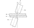
- LME cracks are cracks that occur when the zinc in the galvanized layer melts due to the heat generated during spot welding, the molten zinc invades the grain boundaries of the steel plate structure of the weld, and tensile stress acts on that state. ..
- LME cracking even if one is a cold-rolled steel sheet that has not been galvanized, if the other is a galvanized steel sheet, the zinc melted by the galvanized steel sheet comes into contact with the cold-rolled steel sheet during spot welding. May cause LME cracking. Further, LME cracking occurs remarkably especially when a high-strength TRIP steel sheet (transformation-induced plastic steel sheet) is spot-welded.
- the high-strength TRIP steel sheet is a steel sheet having a higher concentration of C, Si, and Mn than a normal high-strength steel sheet and having excellent energy absorption capacity and press formability by containing retained austenite.
- Hydrogen embrittlement cracking is a phenomenon in which a steel member under high stress under usage conditions suddenly breaks due to hydrogen that has entered the steel from the environment. This phenomenon is also called delayed fracture because of the form of fracture.
- hydrogen embrittlement cracking of a steel sheet is more likely to occur as the tensile strength of the steel sheet increases. It is considered that this is because the higher the tensile strength of the steel sheet, the greater the stress remaining on the steel sheet after forming the part.
- the sensitivity to hydrogen embrittlement cracking is called hydrogen embrittlement resistance.
- hydrogen embrittlement cracking is particularly likely to occur in the bent portion where a large plastic strain is applied. Therefore, when a high-strength steel sheet is used for an automobile member, it is required to improve not only formability such as elongation, bendability, and hole expandability, but also hydrogen embrittlement resistance of the bent portion.
- High-strength steel plates used for vehicle bodies are liable to become brittle due to hydrogen in the steel, and are liable to crack or break at low stress when stress such as bending deformation is applied.
- Patent Document 2 describes high strength with excellent ductility and hole widening property, excellent chemical conversion treatment property, plating adhesion property, fatigue property and hydrogen embrittlement resistance property of bent portion. Steel plates are disclosed.
- Patent Document 2 is excellent in hydrogen embrittlement resistance of the bent portion, but when punched, hydrogen embrittlement may occur at the punched end face. Concerned, it turned out that it may not be possible to meet the demand for higher collision characteristics in recent years.
- the present invention provides a steel sheet having high strength and excellent formability (particularly uniform elongation), collision resistance (particularly punched portion), and LME resistance during spot welding, and a method for manufacturing the same. The purpose is to do.
- the present invention has been made based on the above findings, and the gist thereof is as follows.
- the steel plate according to one aspect of the present invention has a chemical composition of% by mass, C: 0.10 to 0.40%, Si: 0.10 to 1.20%, Al: 0.30 to 1. .50%, Mn: 1.0 to 4.0%, P: 0.0200% or less, S: 0.0200% or less, N: 0.0200% or less, O: 0.0200% or less, Ni: 0 ⁇ 1.00%, Mo: 0 to 0.50%, Cr: 0 to 2.00%, Ti: 0 to 0.100%, B: 0 to 0.0100%, Nb: 0 to 0.10% , V: 0 to 0.50%, Cu: 0 to 0.50%, W: 0 to 0.10%, Ta: 0 to 0.100%, Co: 0 to 0.50%, Mg: 0 to 0.050%, Ca: 0 to 0.0500%, Y: 0 to 0.050%, Zr: 0 to 0.050%, La: 0 to 0.0500%, Ce: 0 to 0.05
- the volume ratio of retained austenite is 3% or more and 20% or less
- the balance is one or two kinds of fresh martensite and tempered martensite
- the aspect ratio is Retained austenite having a thickness of 3.0 or more occupies 80% or more of the total retained austenite in terms of area ratio
- the internal oxide layer having a thickness from the surface of the steel plate of 4.0 ⁇ m or more and the steel plate. It has a decarburized layer having a thickness from the surface of 10 ⁇ m or more and 100 ⁇ m or less, and the amount of diffusible hydrogen contained in the steel plate is 1.00 ppm or less on a mass basis.
- the steel sheet according to the above [1] may have a hot-dip galvanized layer on the surface.
- the steel sheet according to the above [1] may have an alloyed hot-dip galvanized layer on the surface.
- the method for producing a steel sheet according to another aspect of the present invention includes a hot-rolling step of hot-rolling a slab having the chemical composition according to [1] to obtain a hot-rolled steel sheet, and the hot-rolled steel sheet. Is cooled at a cooling rate of 5 ° C./s or higher and wound up at 400 ° C. or lower, and the hot-rolled steel sheet after the winding step is pickled and then 0.5% or more and 20.0%.
- the cold-rolled steel sheet is held at a holding temperature of Ac1 to Ac3 ° C. for 1 second or more and 1000 seconds or less, and the cold-rolled steel sheet after the holding is cooled to 100 to 340 ° C. at an average cooling rate of 4 ° C./s or more.
- the cooled rolled steel sheet is reheated and held at 350 ° C. or higher and 480 ° C. or lower for 80 seconds or longer.
- t -2.4 ⁇ T + 96 (1)
- T: is the average temperature (° C.) when left unattended.
- the cold-rolled steel sheet after the baking step is further subjected to a temperature range of (zinc plating bath temperature ⁇ 40) ° C. to (zinc plating bath temperature +50) ° C. It may have a hot-dip galvanizing step of forming hot-dip galvanizing on the surface of the cold-rolled steel sheet by immersing it in a hot-dip galvanizing bath.
- the method for manufacturing a steel sheet according to the above [5] may further include an alloying step of heating the hot-dip galvanized steel sheet to a temperature range of 300 to 500 ° C. to alloy the plated layer. good.
- the steel sheet according to this embodiment has a predetermined chemical composition described later and has a predetermined chemical composition.
- the volume fractions of ferrite, bainite, and pearlite are 0% or more and 50% or less in total.
- the volume fraction of retained austenite is 3% or more and 20% or less.
- the rest is one or two types of fresh martensite and tempered martensite.
- Retained austenite having an aspect ratio of 3.0 or more accounts for 80% or more of the total retained austenite in terms of area ratio.
- It has an internal oxide layer having a thickness of 4.0 ⁇ m or more from the surface of the steel sheet and a decarburized layer having a thickness of 10 ⁇ m or more and 100 ⁇ m or less from the surface of the steel sheet.
- the amount of diffusible hydrogen contained in the steel sheet is 1.00 ppm or less on a mass basis.
- the metal structure (microstructure) of the steel sheet according to this embodiment will be described.
- the tissue fraction is expressed as a volume fraction
- the unit "%" of the tissue fraction means volume percent unless otherwise specified.
- Those that identify the tissue fraction by image processing consider the area fraction as the volume fraction.
- the metallographic structure of the steel sheet according to the present embodiment represents a metallographic structure at 1/4 part of the plate thickness (position at a depth of 1/4 of the plate thickness in the plate thickness direction from the surface).
- the reason for defining the metal structure of 1/4 part of the plate thickness is that in the plate thickness direction, in the vicinity of the surface and the vicinity of the center of the plate thickness, the microstructure (component) of the steel sheet becomes the other part due to decarburization and Mn segregation, respectively. This is because the metal structure of 1/4 part of the plate thickness may be a typical structure of the steel sheet.
- Bainite is a tissue obtained by holding it at 350 ° C or higher and 450 ° C or lower for a certain period of time after annealing. Bainite is a tissue that contributes to improved elongation because it is soft against martensite. However, in order to obtain the desired high strength, it is necessary to limit the volume fraction as in the case of ferrite.
- Pearlite is a structure that contains hard iron carbide and is the starting point for the generation of voids when expanding holes.
- the volume fractions of ferrite, bainite and pearlite are 50% or less in total.
- the total volume fraction of ferrite, bainite and pearlite may be 40% or less in total. Since ferrite, bainite and pearlite are not essential to obtain the effect of this embodiment, the lower limit thereof is 0%.
- Retained austenite is a tissue that contributes to the improvement of elongation (particularly uniform elongation) by the TRIP effect.
- the volume fraction of retained austenite is set to 3% or more.
- the volume fraction of retained austenite is preferably 5% or more, more preferably 7% or more.
- the volume fraction of retained austenite becomes excessive, the particle size of retained austenite becomes large.
- Retained austenite having such a large particle size becomes coarse and hard martensite after deformation. In this case, it is not preferable because it tends to be a starting point of cracking and the hole expanding property is deteriorated. Therefore, the volume fraction of retained austenite is set to 20% or less.
- the volume fraction of retained austenite is preferably 18% or less, more preferably 16% or less.
- the stability of the retained austenite is enhanced by controlling not only the volume fraction of the retained austenite but also the aspect ratio of the retained austenite. Since the stability of the retained austenite is high, the process-induced transformation to the fresh martensite phase, which is a hard phase, can be suppressed, so that the uniform elongation is improved.
- Fresh martensite and / or tempered martensite The remainder other than the above-mentioned ferrite, bainite, pearlite, and retained austenite is one or two of fresh martensite and tempered martensite. Since fresh martensite is a hard structure with a high dislocation density, it is a structure that contributes to the improvement of tensile strength. Tempering martensite, like fresh martensite, is a collection of lath-shaped crystal grains and is a structure that contributes to the improvement of tensile strength. On the other hand, tempered martensite is a hard structure containing fine iron-based carbides inside due to tempering, unlike fresh martensite.
- Tempering martensite is obtained by tempering fresh martensite produced by cooling after annealing by heat treatment or the like. Considering the volume fractions of ferrite, bainite, pearlite, and retained austenite, the total volume fraction of fresh martensite and tempered martensite is 30 to 97%.
- the volume fraction of retained austenite can be calculated by measuring the diffraction intensity using X-rays.
- the surface of the sample cut out from the steel sheet to the 1/4 depth position of the plate thickness is removed by mechanical polishing and chemical polishing, and MoK ⁇ rays are emitted on the polished surface (1/4 depth position).
- X-ray diffraction was performed using the sample, and the texture of retained austenite was determined from the integrated intensity ratios of the diffraction peaks of the bcc phase (200) and (211) and the fcc phase (200), (220) and (311). Calculate the rate.
- the 5-peak method is used as a general calculation method.
- the volume fraction of fresh martensite is determined by the following procedure. Samples are taken so that the cross section of the plate thickness parallel to the rolling direction of the steel plate is the observation surface.
- the observation surface of the sample is etched with a reperer solution, and the electric field is applied to a region of 100 ⁇ m ⁇ 100 ⁇ m within the range of 1/8 to 3/8 of the plate thickness from the surface centered on the 1/4 depth position of the plate thickness from the surface. It is determined from the obtained secondary electron image by observing with a radiation scanning electron microscope (FE-SEM) at a magnification of 3000 times.
- FE-SEM radiation scanning electron microscope
- the area ratio of the uncorroded area is the total area ratio of fresh martensite and retained austenite.
- the area ratio of this uncorroded area is regarded as the total area ratio of fresh martensite and retained austenite, and the volume ratio of retained austenite measured by the above-mentioned X-ray is subtracted from this total area ratio. Calculate the volume fraction of fresh martensite.
- the volume ratios of ferrite, bainite, pearlite, and tempered martensite can be observed by FE-SEM and determined from the obtained secondary electron image.
- the observation surface shall be a sheet thickness cross section parallel to the rolling direction of the steel sheet. Polishing and night-game etching are performed on the observation surface, and 100 ⁇ m within the range of 1/8 to 3/8 of the plate thickness from the surface centered on the position of 1/4 depth from the surface on the observation surface. A region of ⁇ 100 ⁇ m is observed at a magnification of 3000 times. By leaving a plurality of indentations around the region observed by the above-mentioned repeller corrosion, the same region as the region observed by the repeller corrosion can be confirmed.
- Bainite is a collection of lath-shaped crystal grains that does not contain iron-based carbides with a major axis of 20 nm or more inside, or contains iron-based carbides with a major axis of 20 nm or more inside, and the carbides are a single variant. That is, it belongs to a group of iron-based carbides extending in the same direction.
- the iron-based carbide group elongated in the same direction means that the difference in the elongation direction of the iron-based carbide group is within 5 °.
- Tempering martensite is a collection of lath-shaped crystal grains and contains iron-based carbides with a major axis of 20 nm or more inside, but cementite in the structure has multiple variants. Further, the region where cementite is deposited in a lamellar shape is pearlite. Based on these differences, each tissue is identified and the area ratio is calculated by image processing. Then, in the present embodiment, as described above, the value obtained by calculating the area ratio by image processing is regarded as the volume ratio.
- retained austenite with aspect ratio of 3.0 or more: 80 area% or more of total retained austenite By forming the retained austenite into a needle shape, the stability when subjected to strain is improved. Specifically, retained austenite gradually transforms from grain boundaries to martensite, and distortion occurs with this transformation. As the transformation progresses, the dislocations generated near the grain boundaries move through the grains to the opposite grain boundaries, and the dislocations are accumulated. When the retained austenite is needle-shaped, the distance from the vicinity of the grain boundary where dislocations occur to the grain boundaries where dislocations are accumulated is short.
- the retained austenite is formed into a needle shape by the method described later, but the retained austenite generated without controlling the shape does not have a needle-like structure, and the stability varies in each retained austenite. Therefore, the uniform elongation deteriorates.
- "retained austenite having an aspect ratio of 3.0 or more” is defined as “needle-shaped retained austenite”.
- the retained austenite having an aspect ratio of 3.0 or more is 80% or more of the total retained austenite, the uniform elongation is improved and the hydrogen embrittlement resistance is improved.
- the retained austenite having an aspect ratio of 3.0 or more is preferably 83% or more, more preferably 85% or more of the total retained austenite.
- the upper limit of the ratio of retained austenite having an aspect ratio of 3.0 or more to the total retained austenite is not particularly set, and is ideally 100%.
- the "ratio" referred to here is an area ratio as described later.
- the upper limit of the aspect ratio of the retained austenite that defines the area ratio is not limited, but if the aspect ratio is high, it becomes the starting point of void generation when the residual ⁇ is transformed, and the uniform elongation may decrease. Therefore, the ratio of retained austenite having an aspect ratio of 3.0 to 8.0 is preferably 80% or more.
- the area ratio of the retained austenite having an aspect ratio of 3.0 or more to the total retained austenite is determined by the EBSD analysis method using FE-SEM. Specifically, a sample whose observation surface is a sheet thickness section parallel to the rolling direction of the steel sheet is collected, the observation surface of the sample is polished, the strain-affected layer is removed by electrolytic polishing, and the plate thickness is 1 from the surface. EBSD analysis is performed in a region of 100 ⁇ m ⁇ 100 ⁇ m within the range of 1/8 to 3/8 of the plate thickness from the surface centered on the / 4 depth position, with the measurement step set to 0.05 ⁇ m.
- the magnification of the measurement may be any magnification selected from 1000 to 9000 times, and may be, for example, 3000 times, which is the same as the observation of the SEM-reflected electron image described above.
- Create a retained austenite map from the measured data extract retained austenite with an aspect ratio of 3.0 or more, and obtain the area ratio (area of retained austenite with aspect ratio of 3.0 or more / area of total retained austenite). ..
- the steel sheet according to the present embodiment has an internal oxide layer having a thickness of 4.0 ⁇ m or more from the surface (the internal oxide layer is formed to a depth of at least 4.0 ⁇ m from the surface).
- the internal oxide layer is a layer in which at least a part of the crystal grain boundaries is covered with an oxide of an easily oxidizing element such as Si or Mn. By covering the crystal grain boundaries with the oxide, it is possible to suppress the invasion of the molten metal into the crystal grain boundaries during welding and to suppress the LME cracking during welding. If the thickness of the internal oxide layer is less than 4.0 ⁇ m, the above effect cannot be sufficiently obtained.
- the thickness of the internal oxide layer is set to 4.0 ⁇ m or more.
- the upper limit of the internal oxide layer is preferably 15.0 ⁇ m or less.
- the surface refers to the surface of the base steel sheet (the interface between the plated layer and the base steel sheet).
- the thickness of the internal oxide layer is determined by the following method.
- the plate thickness of the steel plate in the case of a plated steel plate, the plate thickness of the base steel plate
- the position of t / 2 in the plate thickness direction from the surface is defined as the plate thickness center C.
- the Mn concentration distribution is measured by a high-frequency glow discharge emission analyzer (GDS) over a distance of 120 ⁇ m from the surface to the plate thickness center C with the plate thickness cross section parallel to the rolling direction of the steel plate as the measurement surface and the surface of the steel plate as the origin. Measure continuously. Due to the formation of the internal oxide layer, the solid-dissolved Mn around the oxide is deficient and the Mn concentration decreases.
- the Mn concentration is low in the internal oxide layer and increases from the internal oxide layer toward the inside of the plate thickness. , The concentration becomes constant from a certain point. Therefore, the concentration at this constant position is used as the representative concentration inside the steel sheet.
- the position where the Mn concentration becomes 90% of the representative concentration inside the steel sheet is defined as X1, and the distance from the surface to X1 is defined as the thickness of the internal oxide layer. Define.
- a known high frequency GDS analysis method can be used.
- a method is used in which the surface of the steel sheet is made into an Ar atmosphere, a voltage is applied to generate glow plasma, and the surface of the steel sheet is sputtered to analyze in the depth direction. Then, the element contained in the material (steel plate) is identified from the emission spectrum wavelength peculiar to the element emitted by exciting the atom in the glow plasma, and the amount of the element contained in the material is estimated from the emission intensity of the identified element.
- the data in the depth direction can be estimated from the spatter time. Specifically, the spatter time can be converted into the spatter depth by obtaining the relationship between the spatter time and the spatter depth in advance using a standard sample. Therefore, the sputter depth converted from the sputter time can be defined as the depth from the surface of the material. For high frequency GDS analysis, a commercially available analyzer can be used.
- the steel sheet according to the present embodiment has a decarburized layer having a thickness of 10 ⁇ m or more from the surface of the steel sheet (the decarburized layer is formed to a depth of at least 10 ⁇ m from the surface). If the thickness of the decarburized layer is less than 10 ⁇ m, the above effect cannot be sufficiently obtained. On the other hand, if the thickness of the decarburized layer exceeds 100 ⁇ m, the strength is insufficient. Therefore, the thickness of the decarburized layer is 100 ⁇ m or less.
- the thickness of the decarburized layer is determined by the following method.
- the region (excluding the plating layer) on the surface side of the steel sheet is defined as the decarburized layer from the deepest position where the average hardness is 80% or less with respect to the average hardness inside the steel sheet.
- the average hardness inside the steel sheet and the average hardness at each position in the thickness direction of the steel sheet are obtained as follows. A sample is taken with the thickness cross section parallel to the rolling direction of the steel sheet as the observation surface, the observation surface is polished to a mirror surface, and chemical polishing is performed using colloidal silica to remove the processed layer on the surface layer.
- the pushing load is set so that the Vickers indentations do not interfere with each other.
- the pushing load is 20 gf.
- the diagonal length of the indentation is measured using an optical microscope, a scanning electron microscope, or the like, and converted into Vickers hardness (Hv).
- the measurement position is moved by 10 ⁇ m or more in the rolling direction, and the same measurement is performed up to a position with a plate thickness of 1/8 with the starting point as a depth position of 10 ⁇ m from the surface.
- the measurement position is moved by 10 ⁇ m or more in the rolling direction, and the same measurement is performed from the surface to the position of 1/8 of the plate thickness, starting from the position at a depth of 5 ⁇ m from the surface.
- the measurement position is moved by 10 ⁇ m or more in the rolling direction, and the same measurement is performed from the outermost layer to the position of 1/8 thickness with the starting point as the depth position of 10 ⁇ m.
- the Vickers hardness of 5 points is measured at each depth position.
- the reason why the measurement interval is not simply set to 5 ⁇ m pitch is to avoid interference between indentations.
- the average value of the five points at the same depth position is taken as the hardness at the thickness position. By interpolating between each data with a straight line, a hardness profile in the depth direction is obtained.
- the hardness at at least 5 points was measured using a micro-hardness measuring device in the same manner as described above.
- the value obtained by averaging the values is taken as the average hardness inside the steel sheet.
- the region on the surface side of the steel sheet is defined as the decarburized layer from the deepest position where the average hardness is 80% or less with respect to the average hardness inside the steel sheet obtained as described above.
- the decarburized layer defined as described above exists in the region having a thickness of 10 to 100 ⁇ m in the plate thickness direction from the surface.
- a decarburized layer having a hardness of 80% or less of the average hardness inside the steel sheet is present on the surface layer portion of the steel sheet, and the thickness of the decarburized layer is 10 to 100 ⁇ m.
- the amount of diffusible hydrogen in the steel sheet is set to 1.00 ppm or less on a mass basis so that the steel sheet has excellent collision resistance even if it has high strength. If the amount of diffusible hydrogen exceeds 1.00 ppm, the collision resistance is deteriorated.
- the amount of diffusible hydrogen is preferably 0.80 ppm or less.
- the hydrogen embrittlement resistance property may be evaluated by the critical diffusible hydrogen amount, but in the steel plate according to the present embodiment, the diffusible hydrogen amount in the steel plate is controlled from the viewpoint of reducing the hydrogen amount at the time of manufacture. is doing.
- the amount of diffusible hydrogen in the steel plate is measured by a temperature-raising hydrogen analysis method using a gas chromatograph (heating rate: 100 ° C / hour, measured up to 300 ° C), and the amount of hydrogen released from the steel material from room temperature to 200 ° C is measured.
- the amount of diffusible hydrogen is measured by a temperature-raising hydrogen analysis method using a gas chromatograph (heating rate: 100 ° C / hour, measured up to 300 ° C), and the amount of hydrogen released from the steel material from room temperature to 200 ° C is measured. The amount of diffusible hydrogen.
- % related to the component composition means mass%.
- C is an element that secures a predetermined amount of martensite (fresh martensite and tempered martensite) and improves the strength of the steel sheet.
- the C content is preferably 0.12% or more.
- the C content is set to 0.40% or less.
- the C content is preferably 0.35% or less.
- Si 0.10% to 1.20% Si is an element useful for improving the strength of steel sheets by solid solution strengthening. Further, since Si suppresses the formation of cementite, it is an effective element for promoting the concentration of C in austenite and forming retained austenite after annealing. Further, Si has an effect of segregating carbon (C) on the ⁇ grain boundary in the annealing step described later. If the Si content is less than 0.10%, it becomes difficult to obtain the effect of the above action, sufficient uniform elongation cannot be obtained, and hydrogen embrittlement resistance deteriorates, which is not preferable. Therefore, the Si content is set to 0.10% or more. The Si content is preferably 0.50% or more, more preferably 0.60% or more.
- the Si content is 1.20% or less.
- the Si content is preferably 1.10% or less, more preferably 1.00% or less.
- Al 0.30% or more, 1.50% or less
- Al is an element having an action of deoxidizing molten steel. Further, Al is an effective element for promoting the concentration of C in austenite and producing retained austenite after annealing because it suppresses the formation of cementite like Si.
- the Si content is set to the above range in order to improve the LME resistance
- the Al content is set to a relatively high range in order to increase the volume fraction of the residual ⁇ . Specifically, when the Al content is less than 0.30%, these effects cannot be sufficiently obtained, so the Al content is set to 0.30% or more.
- the Al content is preferably 0.40% or more, more preferably 0.50% or more.
- the Al content is 1.50% or less.
- the Al content is preferably 1.40% or less, more preferably 1.30% or less.
- Mn 1.0 to 4.0% Mn has an action of improving the hardenability of steel and is an effective element for obtaining the metallographic structure of the present embodiment.
- the Mn content is preferably 1.3% or more.
- the Mn content is set to 4.0% or less.
- the Mn content is preferably 3.5% or less.
- P 0.0200% or less
- P is an impurity element, which segregates in the central portion of the thickness of the steel sheet to reduce toughness and embrittle the welded portion.
- the P content is preferably 0.0100% or less. The smaller the P content is, the more preferable it is, and it may be 0%. However, if the P content is reduced to less than 0.0001% in the practical steel sheet, the manufacturing cost is significantly increased, which is economically disadvantageous. Therefore, the P content may be 0.0001% or more.
- S 0.0200% or less
- S is an impurity element, which is an element that lowers weldability and lowers manufacturability during casting and hot spreading. Further, S is also an element that forms coarse MnS and causes a decrease in hole expandability. When the S content exceeds 0.0200%, the weldability, the manufacturability, and the hole widening property are significantly reduced. Therefore, the S content is 0.0200% or less. The smaller the S content is, the more preferable it is, and it may be 0%. However, if S is reduced to less than 0.0001% in the practical steel sheet, the manufacturing cost is significantly increased, which is economically disadvantageous. Therefore, the S content may be 0.0001% or more.
- N 0.0200% or less
- N is an element that forms a coarse nitride, reduces bendability and hole widening property, and causes blowholes during welding.
- the N content exceeds 0.0200%, the hole expanding property is lowered and the blow hole is remarkably generated. Therefore, the N content is 0.0200% or less.
- the N content may be 0.0001% or more.
- O 0.0200% or less
- O is an element that forms a coarse oxide, reduces bendability and hole widening property, and causes blowholes during welding.
- the O content exceeds 0.0200%, the hole expanding property is lowered and the blow hole is remarkably generated. Therefore, the O content is 0.0200% or less.
- the O content may be 0.0005% or more.
- the balance excluding the above elements is basically Fe and impurities. Impurities are elements that are allowed to exist within a range that is mixed from the steel raw material and / or in the steelmaking process and does not clearly deteriorate the characteristics of the steel sheet according to the present embodiment.
- the chemical composition of the steel plate according to the present embodiment has Ni: 1.00% or less, Mo: 0.50% or less, Cr: 2.
- Ni 0 to 1.00%
- Ni is an element effective in improving the strength of steel sheets.
- the Ni content may be 0%, but in order to obtain the above effect, the Ni content is preferably 0.001% or more.
- the Ni content is more preferably 0.01% or more.
- the Ni content is set to 1.00% or less.
- Mo 0 to 0.50%
- Mo is an element that contributes to increasing the strength of the steel sheet. This effect can be obtained even in a trace amount.
- the Mo content may be 0%, but in order to obtain the above effect, the Mo content is preferably 0.01% or more.
- the Mo content is set to 0.50% or less.
- Cr 0 to 2.00% Cr is an element that improves the hardenability of steel and contributes to high strength, and is an effective element for obtaining the above-mentioned metallographic structure. Therefore, Cr may be contained.
- the Cr content may be 0%, but in order to sufficiently obtain the above effects, the Cr content is preferably 0.01% or more. On the other hand, even if Cr is excessively contained, the effect of the above action is saturated and it becomes uneconomical. Therefore, the Cr content is set to 2.00% or less.
- Ti 0 to 0.100%
- Ti is an element that contributes to an increase in the strength of a steel sheet by strengthening precipitation, strengthening fine grains by suppressing the growth of ferrite crystal grains, and / or strengthening dislocations by suppressing recrystallization.
- the Ti content may be 0%, but in order to sufficiently obtain the above effects, the Ti content is preferably 0.001% or more. In order to further increase the strength of the steel sheet, the Ti content is more preferably 0.010% or more. On the other hand, when the Ti content exceeds 0.100%, the precipitation of carbonitride increases and the moldability deteriorates. Therefore, the Ti content is set to 0.100% or less.
- B 0 to 0.0100%
- B is an element that suppresses the formation of ferrite and pearlite in the metal structure during the cooling process from the austenite temperature range and promotes the formation of a low temperature transformation structure such as bainite or martensite. Further, B is an element useful for increasing the strength of steel. This effect can be obtained even in a trace amount.
- the B content may be 0%, but in order to obtain the above effect, the B content is preferably 0.0001% or more.
- the B content is 0.0100% or less.
- Nb is an element that contributes to the increase in the strength of the steel sheet by strengthening precipitation, strengthening fine grains by suppressing the growth of ferrite crystal grains, and / or strengthening dislocations by suppressing recrystallization.
- the Nb content may be 0%, but the Nb content is preferably 0.01% or more in order to sufficiently obtain the above effects. In order to further increase the strength of the steel sheet, the Nb content is more preferably 0.05% or more.
- the Nb content is set to 0.10% or less. From the viewpoint of moldability, the Nb content is preferably 0.06% or less.
- V 0 to 0.50%
- V is an element that contributes to the increase in the strength of the steel sheet by strengthening precipitation, strengthening fine grains by suppressing the growth of ferrite crystal grains, and / or strengthening dislocations by suppressing recrystallization.
- the V content may be 0%, but in order to sufficiently obtain the above effect, the V content is preferably 0.01% or more, more preferably 0.02% or more.
- the V content is set to 0.50% or less.
- the V content is preferably 0.40% or less.
- Cu 0 to 0.50%
- the Cu content may be 0%, but in order to obtain the above effect, the Cu content is preferably 0.01% or more.
- the Cu content is set to 0.50% or less.
- W 0 to 0.10% W is an element effective for improving the strength of the steel sheet.
- the W content may be 0%, but in order to obtain the above effect, the W content is preferably 0.01% or more.
- the W content is set to 0.10% or less.
- Ta is also an element effective for improving the strength of the steel sheet.
- the Ta content may be 0%, but in order to obtain the above effect, the Ta content is preferably 0.001% or more.
- the Ta content is set to 0.100% or less.
- the Ta content is preferably 0.020% or less, more preferably 0.010% or less.
- Co 0 to 0.50%
- Co is an element effective for improving the strength of the steel sheet.
- the Co content may be 0%, but in order to obtain the above effect, the Co content is preferably 0.01% or more.
- the Co content is set to 0.50% or less.
- Mg 0 to 0.050%
- Mg is an element that controls the morphology of sulfides and oxides and contributes to the improvement of bend formability of steel sheets. Since this effect can be obtained even in a trace amount, the Mg content may be 0%, but in order to obtain the above effect, the Mg content is preferably 0.0001% or more. On the other hand, if the Mg content is too high, the cold formability may deteriorate due to the formation of coarse inclusions. Therefore, the Mg content is set to 0.050% or less. The Mg content is preferably 0.040% or less.
- Ca 0-0.0500%
- the Ca content may be 0%, but in order to obtain the above effect, the Ca content is preferably 0.0010% or more.
- the Ca content is 0.0500% or less.
- the Ca content is preferably 0.0400% or less, more preferably 0.0300% or less.
- Y 0 to 0.050%
- Y is an element that can control the morphology of sulfide with a small amount.
- the Y content may be 0%, but in order to obtain the above effect, the Y content is preferably 0.001% or more.
- the Y content is set to 0.050% or less.
- the Y content is preferably 0.040% or less.
- Zr 0 to 0.050%
- Zr is an element that can control the morphology of sulfide with a small amount.
- the Zr content may be 0%, but in order to obtain the above effect, the Zr content is preferably 0.001% or more.
- the Zr content is set to 0.050% or less.
- the Zr content is preferably 0.040% or less.
- La 0-0.0500%
- the La content may be 0%, but in order to obtain the above effect, the La content is preferably 0.0010% or more.
- the La content is 0.0500% or less.
- the La content is preferably 0.0400% or less.
- Ce 0 to 0.050%
- Ce is an element that can control the morphology of sulfide with a small amount, and is an element that also contributes to the improvement of LME resistance.
- the Ce content is preferably 0.001% or more.
- the Ce content may be 0.002% or more, 0.003% or more, or 0.005% or more.
- the Ce content is set to 0.050% or less.
- the Ce content may be 0.040% or less, 0.020% or less, or 0.010% or less.
- Sn 0 to 0.05%
- Sn is an element that can be contained in a steel sheet when scrap is used as a raw material for the steel sheet. Sn may be contained because it has an effect of improving corrosion resistance, but it is an element that may cause a decrease in cold formability of a steel sheet due to embrittlement of ferrite. If the Sn content is more than 0.05%, the adverse effect becomes remarkable, so the Sn content is set to 0.05% or less.
- the Sn content is preferably 0.04% or less, and may be 0%. However, reducing the Sn content to less than 0.001% leads to an excessive increase in refining cost, so the Sn content may be 0.001% or more.
- Sb 0 to 0.050% Similar to Sn, Sb is an element that can be contained in a steel sheet when scrap is used as a raw material for the steel sheet. Since Sb has an effect of improving corrosion resistance, it may be contained, but it is an element that may cause embrittlement and decrease in elongation of grain boundaries and decrease in cold formability due to strong segregation at grain boundaries. be. If the Sb content is more than 0.050%, the adverse effect becomes remarkable, so the Sb content is set to 0.050% or less. The Sb content is preferably 0.040% or less, and may be 0%. However, reducing the Sb content to less than 0.001% leads to an excessive increase in refining cost, so the Sb content may be 0.001% or more.
- the As content is preferably 0.040% or less, and may be 0%. However, reducing the As content to less than 0.001% leads to an excessive increase in refining cost, so the As content may be 0.001% or more.
- the chemical composition of the steel sheet according to this embodiment can be obtained by the following method.
- the chemical composition of the above-mentioned steel sheet may be measured by a general chemical composition.
- ICP-AES Inductively Coupled Plasma-Atomic Emission Spectrum
- C and S may be measured by using the combustion-infrared absorption method
- N may be measured by using the inert gas melting-heat conductivity method
- O may be measured by using the inert gas melting-non-dispersive infrared absorption method.
- the plating layer may be removed by mechanical grinding and then the chemical composition may be analyzed.
- a zinc plating layer may be formed on the surface (both sides or one side) of the steel sheet according to the present embodiment.
- the hot-dip galvanized layer may be an alloyed alloyed hot-dip galvanized layer.
- the chemical composition of the hot-dip galvanized layer of the steel sheet according to the present embodiment is not particularly limited, and may be a known plated layer. Further, it is not hindered that the steel sheet according to the present embodiment has another plating (for example, aluminum plating).
- the Fe content in the hot-dip galvanized layer is preferably less than 7.0% by mass.
- the hot-dip galvanized layer is an alloyed alloyed hot-dip galvanized layer
- the Fe content is preferably 6.0% by mass or more. More preferably, it is 7.0% by mass or more.
- the alloyed hot-dip galvanized steel sheet has better weldability than the hot-dip galvanized steel sheet.
- an upper plating layer may be further provided on the zinc plating layer and the zinc plating layer for the purpose of improving coatability, weldability, and the like.
- the zinc-plated steel sheet may be subjected to various treatments such as chromate treatment, phosphate treatment, lubricity improvement treatment, weldability improvement treatment and the like.
- the tensile strength (TS) is targeted to be 980 MPa or more in consideration of the contribution to the improvement of the fuel efficiency of the automobile.
- the upper limit of the tensile strength is not particularly limited, but may be 1310 MPa or less in terms of moldability.
- the uniform elongation (u-El) is targeted to be 7.0% or more from the viewpoint of formability.
- the upper limit of uniform elongation is not particularly limited.
- Tensile strength and uniform elongation are measured by collecting a JIS No. 5 tensile test piece described in JIS Z 2241: 2011 from a steel sheet in a direction perpendicular to the rolling direction and performing a tensile test along JIS Z 2241: 2011. do.
- the steel sheet according to the present embodiment has excellent hydrogen embrittlement resistance at the punched end face, it has excellent collision resistance.
- the tensile strength when a semi-circular punched hole with a diameter of 10 mm is made in the center of both ends of the JIS No. 5 tensile test piece and pulled along JIS Z 2241: 2011 is the center of both ends of the JIS No. 5 tensile test piece.
- the tensile strength is TS2
- R TS1 / TS2
- the value of R is 0. It is preferably .93 or more.
- the steel plate according to the present embodiment is, for example, two steel plates having at least one zinc-plated steel plate at a pressure of 450 kgf (4413 kgm / m /) using a servomotor pressure type single-phase AC spot welder (power supply frequency 50 Hz). While pressurizing in s2), the current value is 6.5 kA, the inclination angle of the electrode is 3 °, there is no upslope, the energization time is 0.4 seconds, and the holding time after energization is 0.1 seconds.
- the steel sheet according to this embodiment can be manufactured by a manufacturing method including the following steps.
- An annealing step of annealing the cold-rolled steel sheet after the hydrogen amount reducing step. t -2.4 ⁇ T + 96 (1)
- T is the average temperature (° C.) when left unattended.
- preferable conditions will be described for each step. Known conditions can be applied to the conditions not described.
- a slab having the above-mentioned chemical composition (the same chemical composition as that of the steel sheet according to the present embodiment) is hot-rolled to obtain a hot-rolled steel sheet.
- the slab to be subjected to hot rolling is not particularly limited as long as it has the above-mentioned chemical composition, and may be a slab produced by a conventional method.
- the slab may be a slab manufactured by a general method such as a continuously cast slab or a thin slab caster.
- hot rolling rough rolling and finish rolling are performed.
- finish rolling the slab after rough rolling is rolled by a plurality of finish rolling mills.
- the heating temperature and holding time of the slab before hot rolling are not particularly limited.
- the plate thickness of the hot-rolled steel sheet obtained by hot rolling is not particularly specified, but if the plate thickness is less than 1.0 mm, the plate may be broken during the annealing process. If the plate thickness is thicker than 6.0 mm, the steel plate is heavy, and even if tension is applied during plate passage, it does not become taut and may meander. Therefore, it is preferably 1.0 to 6.0 mm.
- the hot-rolled steel sheet (hot-rolled steel sheet) as described above has a temperature (rolling) of 400 ° C or lower so that the cooling rate from the hot rolling process end temperature to the winding temperature is always 5 ° C / s or higher. Cool to the taking temperature) and wind up at that temperature.
- the cooling rate minimum cooling rate
- the cooling rate is preferably 10 ° C./s or higher, more preferably 20 ° C./s or higher.
- the upper limit of the cooling rate is not particularly limited, but may be 100 ° C./s or less from the viewpoint of manufacturability. At temperatures below 400 ° C, the cooling rate is not limited.
- the hot-rolled steel sheet after the winding step is pickled and then cold-rolled at a reduction rate of 0.5 to 20.0% to obtain a cold-rolled steel sheet.
- Pickling is a step for removing oxides on the surface of the hot-rolled steel sheet, and may be performed under known conditions. The number of pickling may be one or more.
- the rolling reduction ratio for cold rolling is set to 0.5% or more.
- the reduction rate is preferably 5.0% or more.
- the rolling reduction ratio of cold rolling exceeds 20.0%, the ferrite interface movement is promoted in the heating process of the annealing step, and needle-shaped austenite cannot be obtained.
- the reduction ratio of cold rolling is set to 20.0% or less.
- the rolling reduction of cold rolling is preferably 18.0% or less.
- the cold-rolled steel sheet after the hydrogen content reduction step is bent and bent back at 150 to 400 ° C., and then contains 0.1 to 30.0% by volume of hydrogen and H2O .
- Heating process In the heating process of the annealing step, the steel sheet is bent and bent back with a roll having a radius of 1500 mm or less while the temperature of the steel sheet is 150 to 400 ° C., and the dew point is -20 to 20 ° C., 0.1 to 30.0 volumes. Heat in an atmosphere containing% hydrogen and the balance being nitrogen and impurities. There are two effects by imparting bending back to the steel sheet at 150 to 400 ° C. One is that a sufficient amount of iron-based carbide can be deposited. In this case, the shape of austenite becomes needle-shaped in the heat soaking process described later.
- the lattice spacing inside the steel sheet can be repeatedly changed, and hydrogen on the surface layer can be released to the outside of the steel sheet.
- hydrogen existing inside the steel sheet is also diffused to the surface layer side. If the temperature is less than 150 ° C. when bending back, hydrogen does not diffuse sufficiently, so that the concentration of diffusible hydrogen in the finally obtained steel sheet becomes excessive. Further, when the temperature exceeds 400 ° C., the dislocations imparted by bending and bending back are recovered at a high speed, so that a sufficient amount of iron-based carbide cannot be obtained and needle-shaped austenite cannot be sufficiently obtained.
- the radius of the roll exceeds 1500 mm, it is difficult to efficiently introduce dislocations into the steel sheet structure due to bending-bending back deformation, so the radius of the roll is set to 1500 mm or less.
- the easily oxidizable element is diffused to the surface of the steel sheet. It can prevent and promote internal oxidation. If the amount of hydrogen is less than 0.1% by volume, the oxide film existing on the surface of the steel sheet cannot be sufficiently reduced, and an oxide film is formed on the steel sheet. Therefore, the chemical conversion treatment property and the plating adhesion of the steel sheet obtained after the heat treatment are lowered.
- the amount of hydrogen ( H2 content) in the atmosphere is set to 0.1% or more and 30.0% by volume or less.
- the dew point of the atmosphere is less than ⁇ 20 ° C.
- external oxidation of Si and Mn on the surface layer of the steel sheet occurs, and internal oxidation and decarburization reaction become insufficient.
- the LME resistance and the collision resistance are deteriorated.
- the dew point is more than 20 ° C., an oxide film is formed on the steel sheet to deteriorate the chemical conversion treatment property and the plating adhesion, and the decarburization reaction proceeds excessively.
- Annealing furnaces are roughly divided into three areas: pre-tropical, heated zone and level tropical.
- the atmosphere in the heating zone is the above condition. Atmospheric control is possible even in pre-tropics and average tropics.
- Heat soaking process In the heat soaking process, the cold-rolled steel sheet after the heating process is heated in the temperature range of Ac1 to Ac3 for 1 to 1000 seconds. By soaking under such conditions, needle-shaped austenite is generated along the lath of tempered martensite.
- the specific soaking temperature can be appropriately adjusted based on the Ac1 point (° C.) and the Ac3 point (° C.) represented by the following formulas, taking into consideration the ratio of the desired metal structure.
- Ac1 723-10.7 x Mn-16.9 x Ni + 29.1 x Si + 16.9 x Cr + 290 x As + 6.38 x W ...
- the soaking temperature exceeds Ac3 points, the structure during heat soaking becomes an austenite monophasic structure, and the morphology of the hard structure (low temperature transformation structure) which is the source of the needle-like structure is lost. Therefore, needle-shaped austenite cannot be obtained. Further, if the soaking time is more than 1000 seconds, the productivity is lowered.
- the heat equalization time in the heat equalization process may be set to 300 seconds or less from the viewpoint of suppressing the coarsening of ferrite and austenite during heat equalization.
- the temperature of the steel sheet in the heat soaking process does not have to be constant. If a desired structure ratio can be obtained, the temperature of the steel sheet in the heat soaking step may change within the temperature range of Ac1 to Ac3.
- the cold-rolled steel sheet after the soaking step is cooled to a temperature range of 100 to 340 ° C. so that the average cooling rate is 4 ° C./s or more for the subsequent holding process.
- the average cooling rate is less than 4 ° C./s, ferrite transformation cannot be suppressed.
- the cooling shutdown temperature is less than 100 ° C., the martensite fraction is high.
- the cooling shutdown temperature exceeds 340 ° C., the ferrite, bainite, and pearlite fractions become high, and it becomes difficult to obtain a desired structure.
- the holding process in order to reduce the amount of hydrogen in the steel sheet while increasing the stability of austenite, the cold-rolled steel sheet after the cooling process is reheated to a temperature range of 350 to 480 ° C, and in that temperature range for 80 seconds or more. Hold. If the retention time is less than 80 seconds, carbon is not sufficiently concentrated in the untransformed austenite, and hydrogen cannot be released to the outside of the steel sheet. By setting the holding time in the above temperature range to 80 seconds or more, the carbon concentration in austenite can be increased, and a desired amount of retained austenite can be secured after final cooling. In order to obtain the above effect stably, the holding time is preferably 100 seconds or more.
- the holding time may be 1000 seconds or less because the productivity is lowered if the holding time is excessively long.
- the holding temperature is set to 350 ° C. or higher. It is preferably 380 ° C. or higher.
- the holding temperature is set to 480 ° C. or lower. It is preferably 450 ° C. or lower.
- the conditions for cooling the cold-rolled steel sheet after the holding process to room temperature are not limited, but in order to obtain a stable and desired metal structure, the cold-rolled steel sheet after the holding process has an average cooling rate down to the Ms point or less. It may be cooled to 2 ° C./s or higher.
- the method for manufacturing a steel sheet according to the present embodiment further includes a hot-dip galvanizing step for forming plating on the surface of the cold-rolled steel sheet during the cooling process after annealing, during the holding process, or after the holding process. May be good. Further, after the hot-dip galvanizing step, an alloying step of alloying the plating layer may be further provided.
- the method of hot-dip galvanizing and the method of alloying are not particularly limited, and a conventional method can be used.
- a method of hot-dip galvanizing for example, in the middle of the cooling process, cooling is stopped in a temperature range of (zinc plating bath temperature -40) ° C to (zinc plating bath temperature +50) ° C, and the hot dip galvanizing is controlled in this temperature range to melt.
- Examples thereof include a method of forming hot-dip galvanizing by immersing in a zinc plating bath.
- an alloying method for example, a method of alloying hot dip galvanizing in a temperature range of 300 to 500 ° C. can be mentioned.
- a slab having the chemical composition shown in Table 1 was cast.
- the cast slab was heated to the temperature shown in Table 2 and then hot-rolled to a thickness of 1.0 to 6.0 mm.
- the hot-rolled steel sheet was cooled under the conditions shown in Table 2 and wound up, and then cold-rolled under the conditions shown in Table 2 to obtain a cold-rolled steel sheet.
- These cold-rolled steel sheets were left in the air under the conditions shown in Table 3 to reduce the amount of hydrogen.
- annealing was performed under the conditions shown in Tables 3 and 4.
- An example of bending-bending back was performed on a roll having a radius of roll diameter of 1100 mm in a temperature range of 150 to 400 ° C.
- plating was performed by controlling the temperature in the temperature range of (zinc plating bath temperature ⁇ 40) ° C. to (zinc plating bath temperature +50) ° C. and then immersing in a hot-dip galvanizing bath.
- the steel sheet was heated to a temperature range of 300 to 500 ° C. to alloy the plating layer.
- GI is an example of hot-dip galvanizing
- GA is an example of alloyed hot-dip galvanizing.
- a test piece for SEM observation is collected from the obtained steel sheet (annealed steel sheet or steel sheet plated after annealing), and after polishing the vertical cross section parallel to the rolling direction, the plate thickness is 1 as described above.
- the metallographic structure at the / 4 position was observed, and the area ratio of each structure (ferrite, bainite, pearlite, balance (fresh martensite and / or annealed martensite)) was measured by image processing, and this was used as the volume ratio. ..
- X-ray diffraction was performed in the same manner as described above to determine the volume fraction of retained austenite. The volume fraction of each tissue is shown in Table 5.
- the area ratio of the retained austenite having an aspect ratio of 3.0 or more in the total retained austenite was obtained by the EBSD analysis method using FE-SEM as described above. The results are shown in Table 5.
- the thickness of the decarburized layer and the thickness of the internal oxide layer were measured as described above.
- the amount of diffusible hydrogen contained in the steel was measured as described above. The results are shown in Table 5.
- TS tensile strength
- u-El uniform elongation
- collision resistance assuming punching collision resistance assuming punching
- LME resistance of spot welds are evaluated by the following methods. did.
- collision resistance The collision resistance characteristics were evaluated by the range of R values shown in the following formula.
- a semi-circular punched hole with a diameter of 10 mm was created at the center of both ends of the JIS No. 5 tensile test piece under the conditions of a punch diameter of 10 mm and a punching clearance of 12 ⁇ 2%, and the tensile strength when pulled along JISZ 2241: 2011.
- Example No. 1 A 50 mm ⁇ 80 mm test piece was collected from the obtained steel sheet. Further, a slab having the chemical composition of A in Table 1 was cast, and after applying the production conditions of Example No. 1, it was immersed in a hot-dip galvanized bath to produce a hot-dip galvanized steel sheet (mate material). A 50 mm ⁇ 80 mm test piece was collected from the manufactured steel sheet (mate material). A steel plate as a mating material was superposed on the test pieces collected from each of the steel plates of Example Nos. 1 to 37, and two steel plates were spot welded as shown in FIG. Specifically, a hot-dip galvanized steel sheet, which is a mating material, is used as the steel sheet 1d in FIG. Spot welded.
- a servomotor pressurized single-phase AC spot welder (power supply frequency 50 Hz) was used, and while pressurizing at a pressure of 450 kgf (4413 kgm / s 2 ), the current value was 6.5 kA and the inclination angle of the electrodes was ⁇ was set to 3 °, no upslope was used, the energization time was 0.4 seconds, and the holding time after the end of energization was 0.1 seconds.
- the structure of the center of the nugget at the joint of the steel sheets was observed using an optical microscope at a magnification of 200 to 1000 times.
- the tensile strength is a value larger than 980 MPa and the uniform elongation is a value larger than 7.0%.
- the evaluation of the index R of the collision resistance was A or B, and the evaluation of the LME resistance (length of crack after spot welding) was A or B.
- the tensile strength is larger than 980 MPa and the uniform elongation is 7.0% or more.
- the evaluation of the index R of the collision resistance characteristic was A or B, and the evaluation of the crack length after spot welding was A or B.
- any of the chemical composition and the structure is out of the scope of the present invention, and any of the tensile strength, uniform elongation, collision resistance, and LME resistance is inferior. rice field.
- Example No. 17 the minimum cooling rate from the hot rolling process end temperature to the take-up temperature was less than 5 ° C./s. Therefore, the proportion of retained austenite having an aspect ratio of 3.0 or more in the structure after annealing was small, and the amount of diffusible hydrogen contained in the steel was large. As a result, uniform elongation and collision resistance were low.
- Example No. 18 the take-up temperature was higher than 400 ° C. Therefore, the proportion of retained austenite having an aspect ratio of 3.0 or more was small, and the amount of diffusible hydrogen contained in the steel was large. As a result, uniform elongation and collision resistance were low.
- Example No. 17 the minimum cooling rate from the hot rolling process end temperature to the take-up temperature was less than 5 ° C./s. Therefore, the proportion of retained austenite having an aspect ratio of 3.0 or more in the structure after annealing was small, and the amount of diffusible hydrogen contained in the steel was large. As a result, uniform elongation and collision resistance
- Example No. 19 since the cold rolling ratio was less than 0.5% in the cold rolling process, the proportion of retained austenite having an aspect ratio of 3.0 or more in the texture after annealing was small and contained in the steel. The amount of diffusible hydrogen was large. As a result, uniform elongation and collision resistance were low.
- Example No. 20 since the cold rolling ratio was more than 20.0% in the cold rolling process, the proportion of retained austenite having an aspect ratio of 3.0 or more in the texture after annealing was small and contained in the steel. The amount of diffusible hydrogen was large. As a result, uniform elongation and collision resistance were low. In Example No.
- Example No. 21 the diffusible hydrogen amount could not be sufficiently reduced because the time left in the atmosphere in the hydrogen amount reduction step was less than -2.4 ⁇ T + 96 (time: hour). As a result, the collision resistance was low.
- Example No. 22 since bending and bending back were not applied in the heating process of the annealing step, the proportion of retained austenite having an aspect ratio of 3.0 or more in the structure after annealing was small, and the diffusivity contained in the steel was small. There was a lot of hydrogen. As a result, uniform elongation and collision resistance were low. In Example No. 23, since the dew point was less than ⁇ 20 ° C.
- Example No. 24 the dew point was more than 20 ° C. in the heating process of the annealing step, so that the thickness of the decarburized layer became excessive. As a result, the tensile strength was low.
- Example No. 25 since the holding temperature was less than Ac1 point in the soaking process of the annealing step, the total area fraction of ferrite, bainite, and pearlite exceeded 50%, and the volume fraction of retained austenite was 0%. .. As a result, the tensile strength was low. In Example No.
- Example No. 26 since the holding temperature was more than Ac3 points in the soaking process of the annealing step, the volume fraction of retained austenite became small, and the proportion of retained austenite having an aspect ratio of 3.0 or more became small. rice field. As a result, the collision resistance and uniform elongation were low.
- Example No. 27 since the average cooling rate was less than 4 ° C./s in the cooling process of the annealing step, the total area ratio of ferrite, bainite, and pearlite exceeded 50%. As a result, the tensile strength was low.
- Example No. 28 since the holding temperature was less than 350 ° C. in the holding process of the annealing step, the retained austenite was not stabilized and the volume fraction of the retained austenite became small.
- Example No. 29 since the holding temperature was over 480 ° C. in the holding process of the annealing step, the total area ratio of ferrite, bainite, and pearlite exceeded 50%. As a result, the tensile strength was low. In Example No. 30, since the holding time was less than 80 seconds in the holding process of the annealing step, the retained austenite was not stabilized and the volume fraction of the retained austenite became small. As a result, the uniform elongation was low.
- Example No. 31 the C content was less than 0.10%, so that the tensile strength was low. In addition, the volume fraction of retained austenite was insufficient. As a result, the uniform elongation was low.
- Example No. 32 the C content was more than 0.40%, so that the LME resistance was lowered.
- Example No. 33 the Si content was less than 0.10%, so that the volume fraction of retained austenite was insufficient. As a result, the uniform elongation was low.
- Example No. 34 the Si content was more than 1.20%, so that the LME resistance was lowered.
- Example No. 35 the volume fraction of retained austenite was insufficient because the Al content was less than 0.30%.
- Example No. 36 the Mn content was less than 1.0%, so that the total area ratio of ferrite, bainite, and pearlite exceeded 50%. As a result, the tensile strength was low.
- Example No. 37 the cold rolling ratio in the cold rolling step was less than 0.5%, and the hydrogen content reduction step was not performed, so that the residual structure after annealing had an aspect ratio of 3.0 or more. The proportion of austenite was small and the amount of diffusible hydrogen contained in the steel was large. As a result, uniform elongation and collision resistance were low.
Landscapes
- Chemical & Material Sciences (AREA)
- Engineering & Computer Science (AREA)
- Materials Engineering (AREA)
- Mechanical Engineering (AREA)
- Metallurgy (AREA)
- Organic Chemistry (AREA)
- Physics & Mathematics (AREA)
- Thermal Sciences (AREA)
- Crystallography & Structural Chemistry (AREA)
- Chemical Kinetics & Catalysis (AREA)
- Oil, Petroleum & Natural Gas (AREA)
- Heat Treatment Of Sheet Steel (AREA)
- Solid-Phase Diffusion Into Metallic Material Surfaces (AREA)
Abstract
Priority Applications (6)
| Application Number | Priority Date | Filing Date | Title |
|---|---|---|---|
| EP21917722.7A EP4223894A4 (fr) | 2021-01-07 | 2021-12-24 | Tôle d'acier et son procédé de production |
| MX2023005834A MX2023005834A (es) | 2021-01-07 | 2021-12-24 | Lamina de acero y metodo para producir la misma. |
| CN202180078137.7A CN116507747A (zh) | 2021-01-07 | 2021-12-24 | 钢板及其制造方法 |
| US18/035,066 US20240011114A1 (en) | 2021-01-07 | 2021-12-24 | Steel sheet and method for producing same |
| KR1020237016576A KR20230086778A (ko) | 2021-01-07 | 2021-12-24 | 강판 및 그 제조 방법 |
| JP2022574012A JPWO2022149502A1 (fr) | 2021-01-07 | 2021-12-24 |
Applications Claiming Priority (2)
| Application Number | Priority Date | Filing Date | Title |
|---|---|---|---|
| JP2021-001682 | 2021-01-07 | ||
| JP2021001682 | 2021-01-07 |
Publications (1)
| Publication Number | Publication Date |
|---|---|
| WO2022149502A1 true WO2022149502A1 (fr) | 2022-07-14 |
Family
ID=82357915
Family Applications (1)
| Application Number | Title | Priority Date | Filing Date |
|---|---|---|---|
| PCT/JP2021/048346 WO2022149502A1 (fr) | 2021-01-07 | 2021-12-24 | Tôle d'acier et son procédé de production |
Country Status (7)
| Country | Link |
|---|---|
| US (1) | US20240011114A1 (fr) |
| EP (1) | EP4223894A4 (fr) |
| JP (1) | JPWO2022149502A1 (fr) |
| KR (1) | KR20230086778A (fr) |
| CN (1) | CN116507747A (fr) |
| MX (1) | MX2023005834A (fr) |
| WO (1) | WO2022149502A1 (fr) |
Cited By (5)
| Publication number | Priority date | Publication date | Assignee | Title |
|---|---|---|---|---|
| CN117187682A (zh) * | 2023-04-28 | 2023-12-08 | 鞍钢股份有限公司 | 新能源汽车用1200MPa电池包用钢及其制备方法 |
| JP7468815B1 (ja) | 2022-10-27 | 2024-04-16 | Jfeスチール株式会社 | 高強度めっき鋼板およびその製造方法 |
| JP7468816B1 (ja) | 2022-10-27 | 2024-04-16 | Jfeスチール株式会社 | 高強度めっき鋼板およびその製造方法 |
| WO2024090033A1 (fr) * | 2022-10-27 | 2024-05-02 | Jfeスチール株式会社 | Tôle d'acier plaquée hautement résistante, et procédé de fabrication de celle-ci |
| WO2024090032A1 (fr) * | 2022-10-27 | 2024-05-02 | Jfeスチール株式会社 | Tôle d'acier plaquée hautement résistante, et procédé de fabrication de celle-ci |
Citations (8)
| Publication number | Priority date | Publication date | Assignee | Title |
|---|---|---|---|---|
| JP2016130357A (ja) * | 2015-01-09 | 2016-07-21 | 株式会社神戸製鋼所 | 高強度めっき鋼板、並びにその製造方法 |
| WO2018043453A1 (fr) | 2016-08-30 | 2018-03-08 | Jfeスチール株式会社 | Tôle d'acier mince et procédé de production de cette dernière |
| WO2019116531A1 (fr) * | 2017-12-15 | 2019-06-20 | 日本製鉄株式会社 | Tôle d'acier, tôle d'acier revêtue de zinc par immersion à chaud et tôle d'acier revêtue de zinc par immersion à chaud alliée |
| WO2019187060A1 (fr) | 2018-03-30 | 2019-10-03 | 日本製鉄株式会社 | Tôle d'acier et son procédé de fabrication |
| WO2020130631A1 (fr) * | 2018-12-19 | 2020-06-25 | 주식회사 포스코 | Tôle d'acier galvanisée à haute résistance ayant une excellente soudabilité par point de résistance électrique et son procédé de fabrication |
| JP2021001682A (ja) | 2019-06-19 | 2021-01-07 | 株式会社ジェイテクト | 密封部材 |
| WO2021200580A1 (fr) * | 2020-03-31 | 2021-10-07 | Jfeスチール株式会社 | Feuille d'acier, élément et leurs procédés de production |
| WO2021200579A1 (fr) * | 2020-03-31 | 2021-10-07 | Jfeスチール株式会社 | Tôle d'acier, élément, et leur procédé de fabrication |
Family Cites Families (1)
| Publication number | Priority date | Publication date | Assignee | Title |
|---|---|---|---|---|
| US11118252B2 (en) * | 2018-03-30 | 2021-09-14 | Nippon Steel Corporation | Galvannealed steel sheet |
-
2021
- 2021-12-24 MX MX2023005834A patent/MX2023005834A/es unknown
- 2021-12-24 JP JP2022574012A patent/JPWO2022149502A1/ja active Pending
- 2021-12-24 EP EP21917722.7A patent/EP4223894A4/fr active Pending
- 2021-12-24 WO PCT/JP2021/048346 patent/WO2022149502A1/fr active Application Filing
- 2021-12-24 US US18/035,066 patent/US20240011114A1/en active Pending
- 2021-12-24 CN CN202180078137.7A patent/CN116507747A/zh active Pending
- 2021-12-24 KR KR1020237016576A patent/KR20230086778A/ko unknown
Patent Citations (8)
| Publication number | Priority date | Publication date | Assignee | Title |
|---|---|---|---|---|
| JP2016130357A (ja) * | 2015-01-09 | 2016-07-21 | 株式会社神戸製鋼所 | 高強度めっき鋼板、並びにその製造方法 |
| WO2018043453A1 (fr) | 2016-08-30 | 2018-03-08 | Jfeスチール株式会社 | Tôle d'acier mince et procédé de production de cette dernière |
| WO2019116531A1 (fr) * | 2017-12-15 | 2019-06-20 | 日本製鉄株式会社 | Tôle d'acier, tôle d'acier revêtue de zinc par immersion à chaud et tôle d'acier revêtue de zinc par immersion à chaud alliée |
| WO2019187060A1 (fr) | 2018-03-30 | 2019-10-03 | 日本製鉄株式会社 | Tôle d'acier et son procédé de fabrication |
| WO2020130631A1 (fr) * | 2018-12-19 | 2020-06-25 | 주식회사 포스코 | Tôle d'acier galvanisée à haute résistance ayant une excellente soudabilité par point de résistance électrique et son procédé de fabrication |
| JP2021001682A (ja) | 2019-06-19 | 2021-01-07 | 株式会社ジェイテクト | 密封部材 |
| WO2021200580A1 (fr) * | 2020-03-31 | 2021-10-07 | Jfeスチール株式会社 | Feuille d'acier, élément et leurs procédés de production |
| WO2021200579A1 (fr) * | 2020-03-31 | 2021-10-07 | Jfeスチール株式会社 | Tôle d'acier, élément, et leur procédé de fabrication |
Non-Patent Citations (1)
| Title |
|---|
| See also references of EP4223894A4 |
Cited By (6)
| Publication number | Priority date | Publication date | Assignee | Title |
|---|---|---|---|---|
| JP7468815B1 (ja) | 2022-10-27 | 2024-04-16 | Jfeスチール株式会社 | 高強度めっき鋼板およびその製造方法 |
| JP7468816B1 (ja) | 2022-10-27 | 2024-04-16 | Jfeスチール株式会社 | 高強度めっき鋼板およびその製造方法 |
| WO2024090033A1 (fr) * | 2022-10-27 | 2024-05-02 | Jfeスチール株式会社 | Tôle d'acier plaquée hautement résistante, et procédé de fabrication de celle-ci |
| WO2024090032A1 (fr) * | 2022-10-27 | 2024-05-02 | Jfeスチール株式会社 | Tôle d'acier plaquée hautement résistante, et procédé de fabrication de celle-ci |
| CN117187682A (zh) * | 2023-04-28 | 2023-12-08 | 鞍钢股份有限公司 | 新能源汽车用1200MPa电池包用钢及其制备方法 |
| CN117187682B (zh) * | 2023-04-28 | 2024-05-14 | 鞍钢股份有限公司 | 新能源汽车用1200MPa电池包用钢及其制备方法 |
Also Published As
| Publication number | Publication date |
|---|---|
| CN116507747A (zh) | 2023-07-28 |
| EP4223894A4 (fr) | 2024-03-13 |
| KR20230086778A (ko) | 2023-06-15 |
| MX2023005834A (es) | 2023-06-02 |
| EP4223894A1 (fr) | 2023-08-09 |
| US20240011114A1 (en) | 2024-01-11 |
| JPWO2022149502A1 (fr) | 2022-07-14 |
Similar Documents
| Publication | Publication Date | Title |
|---|---|---|
| EP3309273B1 (fr) | Tôle d'acier galvanisée et procédé pour sa fabrication | |
| JP5354135B2 (ja) | 機械切断特性に優れた高強度溶融亜鉛めっき鋼板、高強度合金化溶融亜鉛めっき鋼板、並びにそれらの製造方法 | |
| US8840834B2 (en) | High-strength steel sheet and method for manufacturing the same | |
| WO2022149502A1 (fr) | Tôle d'acier et son procédé de production | |
| EP3216886A1 (fr) | Tôle d'acier galvanisée par immersion à chaud | |
| EP2757169A1 (fr) | Tôle d'acier à haute résistance ayant une excellente aptitude au façonnage et son procédé de production | |
| CN114585766B (zh) | 高强度钢板及其制造方法 | |
| CN114981457B (zh) | 高强度镀锌钢板及其制造方法 | |
| JP6760524B1 (ja) | 高強度溶融亜鉛めっき鋼板およびその製造方法 | |
| CN114555845B (zh) | 高强度钢板及其制造方法 | |
| CN114585765B (zh) | 高强度钢板及其制造方法 | |
| WO2021200579A1 (fr) | Tôle d'acier, élément, et leur procédé de fabrication | |
| CN115698361B (zh) | 钢板、构件及它们的制造方法 | |
| JP6947334B1 (ja) | 高強度鋼板およびその製造方法 | |
| CN114585758B (zh) | 高强度钢板和碰撞吸收构件以及高强度钢板的制造方法 | |
| CN115698362B (zh) | 钢板、构件及它们的制造方法 | |
| JP7311808B2 (ja) | 鋼板及びその製造方法 | |
| WO2022196733A1 (fr) | Tôle d'acier, élément en acier et élément en acier revêtu | |
| CN116806274A (zh) | 高强度钢板及其制造方法 |
Legal Events
| Date | Code | Title | Description |
|---|---|---|---|
| 121 | Ep: the epo has been informed by wipo that ep was designated in this application |
Ref document number: 21917722 Country of ref document: EP Kind code of ref document: A1 |
|
| ENP | Entry into the national phase |
Ref document number: 2022574012 Country of ref document: JP Kind code of ref document: A |
|
| WWE | Wipo information: entry into national phase |
Ref document number: 18035066 Country of ref document: US |
|
| ENP | Entry into the national phase |
Ref document number: 2021917722 Country of ref document: EP Effective date: 20230503 |
|
| ENP | Entry into the national phase |
Ref document number: 20237016576 Country of ref document: KR Kind code of ref document: A |
|
| WWE | Wipo information: entry into national phase |
Ref document number: 202180078137.7 Country of ref document: CN |
|
| NENP | Non-entry into the national phase |
Ref country code: DE |