WO2022149502A1 - Steel sheet and method for producing same - Google Patents
Steel sheet and method for producing same Download PDFInfo
- Publication number
- WO2022149502A1 WO2022149502A1 PCT/JP2021/048346 JP2021048346W WO2022149502A1 WO 2022149502 A1 WO2022149502 A1 WO 2022149502A1 JP 2021048346 W JP2021048346 W JP 2021048346W WO 2022149502 A1 WO2022149502 A1 WO 2022149502A1
- Authority
- WO
- WIPO (PCT)
- Prior art keywords
- steel sheet
- less
- hot
- content
- cold
- Prior art date
Links
- 229910000831 Steel Inorganic materials 0.000 title claims abstract description 254
- 239000010959 steel Substances 0.000 title claims abstract description 254
- 238000004519 manufacturing process Methods 0.000 title claims description 20
- 229910001566 austenite Inorganic materials 0.000 claims abstract description 106
- 230000000717 retained effect Effects 0.000 claims abstract description 85
- 229910052739 hydrogen Inorganic materials 0.000 claims abstract description 79
- 239000001257 hydrogen Substances 0.000 claims abstract description 79
- UFHFLCQGNIYNRP-UHFFFAOYSA-N Hydrogen Chemical compound [H][H] UFHFLCQGNIYNRP-UHFFFAOYSA-N 0.000 claims abstract description 76
- 229910000734 martensite Inorganic materials 0.000 claims abstract description 47
- 229910000859 α-Fe Inorganic materials 0.000 claims abstract description 34
- 239000000126 substance Substances 0.000 claims abstract description 29
- 239000000203 mixture Substances 0.000 claims abstract description 24
- 229910001563 bainite Inorganic materials 0.000 claims abstract description 22
- 229910001562 pearlite Inorganic materials 0.000 claims abstract description 22
- 238000000034 method Methods 0.000 claims description 68
- 238000000137 annealing Methods 0.000 claims description 41
- 230000008569 process Effects 0.000 claims description 41
- 238000001816 cooling Methods 0.000 claims description 36
- 239000010960 cold rolled steel Substances 0.000 claims description 34
- 238000007747 plating Methods 0.000 claims description 32
- 238000005097 cold rolling Methods 0.000 claims description 19
- 238000010438 heat treatment Methods 0.000 claims description 19
- HCHKCACWOHOZIP-UHFFFAOYSA-N Zinc Chemical compound [Zn] HCHKCACWOHOZIP-UHFFFAOYSA-N 0.000 claims description 18
- 238000005098 hot rolling Methods 0.000 claims description 18
- 229910052725 zinc Inorganic materials 0.000 claims description 18
- 239000011701 zinc Substances 0.000 claims description 18
- 230000009467 reduction Effects 0.000 claims description 15
- 229910001335 Galvanized steel Inorganic materials 0.000 claims description 14
- 239000008397 galvanized steel Substances 0.000 claims description 14
- 239000012535 impurity Substances 0.000 claims description 12
- 238000004804 winding Methods 0.000 claims description 10
- IJGRMHOSHXDMSA-UHFFFAOYSA-N Atomic nitrogen Chemical compound N#N IJGRMHOSHXDMSA-UHFFFAOYSA-N 0.000 claims description 8
- 229910052757 nitrogen Inorganic materials 0.000 claims description 6
- 238000005554 pickling Methods 0.000 claims description 5
- 229910045601 alloy Inorganic materials 0.000 claims description 3
- 239000000956 alloy Substances 0.000 claims description 3
- 150000002431 hydrogen Chemical class 0.000 claims description 3
- 229910052751 metal Inorganic materials 0.000 abstract description 14
- 239000002184 metal Substances 0.000 abstract description 14
- 230000003647 oxidation Effects 0.000 abstract description 4
- 238000007254 oxidation reaction Methods 0.000 abstract description 4
- 239000010410 layer Substances 0.000 description 67
- 230000000694 effects Effects 0.000 description 43
- XEEYBQQBJWHFJM-UHFFFAOYSA-N iron Substances [Fe] XEEYBQQBJWHFJM-UHFFFAOYSA-N 0.000 description 25
- 238000005096 rolling process Methods 0.000 description 21
- 238000002791 soaking Methods 0.000 description 19
- 238000005246 galvanizing Methods 0.000 description 16
- 230000009466 transformation Effects 0.000 description 16
- 238000005259 measurement Methods 0.000 description 15
- 238000003466 welding Methods 0.000 description 15
- 238000005452 bending Methods 0.000 description 14
- 238000005336 cracking Methods 0.000 description 13
- 230000007423 decrease Effects 0.000 description 13
- 229910052742 iron Inorganic materials 0.000 description 11
- 150000001247 metal acetylides Chemical class 0.000 description 11
- 235000013339 cereals Nutrition 0.000 description 10
- 238000005728 strengthening Methods 0.000 description 10
- 239000013078 crystal Substances 0.000 description 9
- 230000006872 improvement Effects 0.000 description 9
- 239000000463 material Substances 0.000 description 9
- 239000002344 surface layer Substances 0.000 description 9
- 238000011282 treatment Methods 0.000 description 9
- 238000009864 tensile test Methods 0.000 description 8
- 238000005275 alloying Methods 0.000 description 7
- 238000004458 analytical method Methods 0.000 description 7
- 229910052799 carbon Inorganic materials 0.000 description 7
- 238000001556 precipitation Methods 0.000 description 7
- 230000015572 biosynthetic process Effects 0.000 description 6
- 229910001567 cementite Inorganic materials 0.000 description 6
- 238000006243 chemical reaction Methods 0.000 description 6
- 238000005260 corrosion Methods 0.000 description 6
- 230000007797 corrosion Effects 0.000 description 6
- 238000011156 evaluation Methods 0.000 description 6
- 238000005498 polishing Methods 0.000 description 6
- 229910052791 calcium Inorganic materials 0.000 description 5
- KSOKAHYVTMZFBJ-UHFFFAOYSA-N iron;methane Chemical compound C.[Fe].[Fe].[Fe] KSOKAHYVTMZFBJ-UHFFFAOYSA-N 0.000 description 5
- 229910052749 magnesium Inorganic materials 0.000 description 5
- 229910052748 manganese Inorganic materials 0.000 description 5
- 238000012545 processing Methods 0.000 description 5
- 229910052710 silicon Inorganic materials 0.000 description 5
- 238000005496 tempering Methods 0.000 description 5
- UCKMPCXJQFINFW-UHFFFAOYSA-N Sulphide Chemical compound [S-2] UCKMPCXJQFINFW-UHFFFAOYSA-N 0.000 description 4
- 230000009471 action Effects 0.000 description 4
- 229910052787 antimony Inorganic materials 0.000 description 4
- 229910052804 chromium Inorganic materials 0.000 description 4
- 238000005261 decarburization Methods 0.000 description 4
- 238000000445 field-emission scanning electron microscopy Methods 0.000 description 4
- 229910052750 molybdenum Inorganic materials 0.000 description 4
- 239000002994 raw material Substances 0.000 description 4
- 238000012360 testing method Methods 0.000 description 4
- 229910052727 yttrium Inorganic materials 0.000 description 4
- OKTJSMMVPCPJKN-UHFFFAOYSA-N Carbon Chemical compound [C] OKTJSMMVPCPJKN-UHFFFAOYSA-N 0.000 description 3
- 238000010521 absorption reaction Methods 0.000 description 3
- 230000002411 adverse Effects 0.000 description 3
- 229910052782 aluminium Inorganic materials 0.000 description 3
- 229910052785 arsenic Inorganic materials 0.000 description 3
- 229910052802 copper Inorganic materials 0.000 description 3
- 238000001887 electron backscatter diffraction Methods 0.000 description 3
- 238000007373 indentation Methods 0.000 description 3
- 238000004080 punching Methods 0.000 description 3
- 238000001953 recrystallisation Methods 0.000 description 3
- 238000007670 refining Methods 0.000 description 3
- 238000005204 segregation Methods 0.000 description 3
- 229910052718 tin Inorganic materials 0.000 description 3
- 229910052719 titanium Inorganic materials 0.000 description 3
- 229910052721 tungsten Inorganic materials 0.000 description 3
- 229910052726 zirconium Inorganic materials 0.000 description 3
- CURLTUGMZLYLDI-UHFFFAOYSA-N Carbon dioxide Chemical compound O=C=O CURLTUGMZLYLDI-UHFFFAOYSA-N 0.000 description 2
- 229910052684 Cerium Inorganic materials 0.000 description 2
- 241000209094 Oryza Species 0.000 description 2
- 235000007164 Oryza sativa Nutrition 0.000 description 2
- 229910000794 TRIP steel Inorganic materials 0.000 description 2
- 238000002441 X-ray diffraction Methods 0.000 description 2
- 238000004364 calculation method Methods 0.000 description 2
- 238000007796 conventional method Methods 0.000 description 2
- 230000003111 delayed effect Effects 0.000 description 2
- 238000009792 diffusion process Methods 0.000 description 2
- 238000000295 emission spectrum Methods 0.000 description 2
- 239000000446 fuel Substances 0.000 description 2
- 239000011261 inert gas Substances 0.000 description 2
- 229910052746 lanthanum Inorganic materials 0.000 description 2
- 230000033001 locomotion Effects 0.000 description 2
- 230000013011 mating Effects 0.000 description 2
- 230000007246 mechanism Effects 0.000 description 2
- 238000000465 moulding Methods 0.000 description 2
- 229910052759 nickel Inorganic materials 0.000 description 2
- 229910052758 niobium Inorganic materials 0.000 description 2
- QJGQUHMNIGDVPM-UHFFFAOYSA-N nitrogen group Chemical group [N] QJGQUHMNIGDVPM-UHFFFAOYSA-N 0.000 description 2
- 230000003287 optical effect Effects 0.000 description 2
- 239000002245 particle Substances 0.000 description 2
- 229910052698 phosphorus Inorganic materials 0.000 description 2
- 230000001737 promoting effect Effects 0.000 description 2
- 235000009566 rice Nutrition 0.000 description 2
- 229910052717 sulfur Inorganic materials 0.000 description 2
- 229910052715 tantalum Inorganic materials 0.000 description 2
- 150000003568 thioethers Chemical class 0.000 description 2
- 229910052720 vanadium Inorganic materials 0.000 description 2
- 238000012935 Averaging Methods 0.000 description 1
- 229910019142 PO4 Inorganic materials 0.000 description 1
- VYPSYNLAJGMNEJ-UHFFFAOYSA-N Silicium dioxide Chemical compound O=[Si]=O VYPSYNLAJGMNEJ-UHFFFAOYSA-N 0.000 description 1
- 229910000797 Ultra-high-strength steel Inorganic materials 0.000 description 1
- 238000007545 Vickers hardness test Methods 0.000 description 1
- XAGFODPZIPBFFR-UHFFFAOYSA-N aluminium Chemical compound [Al] XAGFODPZIPBFFR-UHFFFAOYSA-N 0.000 description 1
- 125000004429 atom Chemical group 0.000 description 1
- 229910002092 carbon dioxide Inorganic materials 0.000 description 1
- 239000001569 carbon dioxide Substances 0.000 description 1
- 238000005266 casting Methods 0.000 description 1
- 230000008859 change Effects 0.000 description 1
- ZCDOYSPFYFSLEW-UHFFFAOYSA-N chromate(2-) Chemical compound [O-][Cr]([O-])(=O)=O ZCDOYSPFYFSLEW-UHFFFAOYSA-N 0.000 description 1
- 239000008119 colloidal silica Substances 0.000 description 1
- 230000000052 comparative effect Effects 0.000 description 1
- 230000002950 deficient Effects 0.000 description 1
- 238000009826 distribution Methods 0.000 description 1
- 230000005684 electric field Effects 0.000 description 1
- 238000005530 etching Methods 0.000 description 1
- 238000004880 explosion Methods 0.000 description 1
- 239000007789 gas Substances 0.000 description 1
- 238000007429 general method Methods 0.000 description 1
- 238000000227 grinding Methods 0.000 description 1
- 238000007542 hardness measurement Methods 0.000 description 1
- 230000001771 impaired effect Effects 0.000 description 1
- 230000009545 invasion Effects 0.000 description 1
- 150000002505 iron Chemical class 0.000 description 1
- 229910001338 liquidmetal Inorganic materials 0.000 description 1
- 230000014759 maintenance of location Effects 0.000 description 1
- 239000000155 melt Substances 0.000 description 1
- 150000004767 nitrides Chemical class 0.000 description 1
- 230000001590 oxidative effect Effects 0.000 description 1
- 229910052760 oxygen Inorganic materials 0.000 description 1
- NBIIXXVUZAFLBC-UHFFFAOYSA-K phosphate Chemical compound [O-]P([O-])([O-])=O NBIIXXVUZAFLBC-UHFFFAOYSA-K 0.000 description 1
- 239000010452 phosphate Substances 0.000 description 1
- 230000005855 radiation Effects 0.000 description 1
- 238000011946 reduction process Methods 0.000 description 1
- 230000004044 response Effects 0.000 description 1
- 229920006395 saturated elastomer Polymers 0.000 description 1
- 230000035945 sensitivity Effects 0.000 description 1
- 239000006104 solid solution Substances 0.000 description 1
- 239000000243 solution Substances 0.000 description 1
- 238000003892 spreading Methods 0.000 description 1
- 230000007480 spreading Effects 0.000 description 1
- 238000009628 steelmaking Methods 0.000 description 1
- 238000010998 test method Methods 0.000 description 1
- 239000011800 void material Substances 0.000 description 1
Images
Classifications
-
- C—CHEMISTRY; METALLURGY
- C22—METALLURGY; FERROUS OR NON-FERROUS ALLOYS; TREATMENT OF ALLOYS OR NON-FERROUS METALS
- C22C—ALLOYS
- C22C38/00—Ferrous alloys, e.g. steel alloys
- C22C38/18—Ferrous alloys, e.g. steel alloys containing chromium
- C22C38/40—Ferrous alloys, e.g. steel alloys containing chromium with nickel
- C22C38/58—Ferrous alloys, e.g. steel alloys containing chromium with nickel with more than 1.5% by weight of manganese
-
- C—CHEMISTRY; METALLURGY
- C21—METALLURGY OF IRON
- C21D—MODIFYING THE PHYSICAL STRUCTURE OF FERROUS METALS; GENERAL DEVICES FOR HEAT TREATMENT OF FERROUS OR NON-FERROUS METALS OR ALLOYS; MAKING METAL MALLEABLE, e.g. BY DECARBURISATION OR TEMPERING
- C21D1/00—General methods or devices for heat treatment, e.g. annealing, hardening, quenching or tempering
- C21D1/18—Hardening; Quenching with or without subsequent tempering
- C21D1/185—Hardening; Quenching with or without subsequent tempering from an intercritical temperature
-
- C—CHEMISTRY; METALLURGY
- C21—METALLURGY OF IRON
- C21D—MODIFYING THE PHYSICAL STRUCTURE OF FERROUS METALS; GENERAL DEVICES FOR HEAT TREATMENT OF FERROUS OR NON-FERROUS METALS OR ALLOYS; MAKING METAL MALLEABLE, e.g. BY DECARBURISATION OR TEMPERING
- C21D1/00—General methods or devices for heat treatment, e.g. annealing, hardening, quenching or tempering
- C21D1/18—Hardening; Quenching with or without subsequent tempering
- C21D1/25—Hardening, combined with annealing between 300 degrees Celsius and 600 degrees Celsius, i.e. heat refining ("Vergüten")
-
- C—CHEMISTRY; METALLURGY
- C21—METALLURGY OF IRON
- C21D—MODIFYING THE PHYSICAL STRUCTURE OF FERROUS METALS; GENERAL DEVICES FOR HEAT TREATMENT OF FERROUS OR NON-FERROUS METALS OR ALLOYS; MAKING METAL MALLEABLE, e.g. BY DECARBURISATION OR TEMPERING
- C21D1/00—General methods or devices for heat treatment, e.g. annealing, hardening, quenching or tempering
- C21D1/26—Methods of annealing
-
- C—CHEMISTRY; METALLURGY
- C21—METALLURGY OF IRON
- C21D—MODIFYING THE PHYSICAL STRUCTURE OF FERROUS METALS; GENERAL DEVICES FOR HEAT TREATMENT OF FERROUS OR NON-FERROUS METALS OR ALLOYS; MAKING METAL MALLEABLE, e.g. BY DECARBURISATION OR TEMPERING
- C21D1/00—General methods or devices for heat treatment, e.g. annealing, hardening, quenching or tempering
- C21D1/74—Methods of treatment in inert gas, controlled atmosphere, vacuum or pulverulent material
- C21D1/76—Adjusting the composition of the atmosphere
-
- C—CHEMISTRY; METALLURGY
- C21—METALLURGY OF IRON
- C21D—MODIFYING THE PHYSICAL STRUCTURE OF FERROUS METALS; GENERAL DEVICES FOR HEAT TREATMENT OF FERROUS OR NON-FERROUS METALS OR ALLOYS; MAKING METAL MALLEABLE, e.g. BY DECARBURISATION OR TEMPERING
- C21D3/00—Diffusion processes for extraction of non-metals; Furnaces therefor
- C21D3/02—Extraction of non-metals
- C21D3/04—Decarburising
-
- C—CHEMISTRY; METALLURGY
- C21—METALLURGY OF IRON
- C21D—MODIFYING THE PHYSICAL STRUCTURE OF FERROUS METALS; GENERAL DEVICES FOR HEAT TREATMENT OF FERROUS OR NON-FERROUS METALS OR ALLOYS; MAKING METAL MALLEABLE, e.g. BY DECARBURISATION OR TEMPERING
- C21D3/00—Diffusion processes for extraction of non-metals; Furnaces therefor
- C21D3/02—Extraction of non-metals
- C21D3/06—Extraction of hydrogen
-
- C—CHEMISTRY; METALLURGY
- C21—METALLURGY OF IRON
- C21D—MODIFYING THE PHYSICAL STRUCTURE OF FERROUS METALS; GENERAL DEVICES FOR HEAT TREATMENT OF FERROUS OR NON-FERROUS METALS OR ALLOYS; MAKING METAL MALLEABLE, e.g. BY DECARBURISATION OR TEMPERING
- C21D8/00—Modifying the physical properties by deformation combined with, or followed by, heat treatment
- C21D8/02—Modifying the physical properties by deformation combined with, or followed by, heat treatment during manufacturing of plates or strips
- C21D8/0205—Modifying the physical properties by deformation combined with, or followed by, heat treatment during manufacturing of plates or strips of ferrous alloys
-
- C—CHEMISTRY; METALLURGY
- C21—METALLURGY OF IRON
- C21D—MODIFYING THE PHYSICAL STRUCTURE OF FERROUS METALS; GENERAL DEVICES FOR HEAT TREATMENT OF FERROUS OR NON-FERROUS METALS OR ALLOYS; MAKING METAL MALLEABLE, e.g. BY DECARBURISATION OR TEMPERING
- C21D8/00—Modifying the physical properties by deformation combined with, or followed by, heat treatment
- C21D8/02—Modifying the physical properties by deformation combined with, or followed by, heat treatment during manufacturing of plates or strips
- C21D8/0221—Modifying the physical properties by deformation combined with, or followed by, heat treatment during manufacturing of plates or strips characterised by the working steps
- C21D8/0226—Hot rolling
-
- C—CHEMISTRY; METALLURGY
- C21—METALLURGY OF IRON
- C21D—MODIFYING THE PHYSICAL STRUCTURE OF FERROUS METALS; GENERAL DEVICES FOR HEAT TREATMENT OF FERROUS OR NON-FERROUS METALS OR ALLOYS; MAKING METAL MALLEABLE, e.g. BY DECARBURISATION OR TEMPERING
- C21D8/00—Modifying the physical properties by deformation combined with, or followed by, heat treatment
- C21D8/02—Modifying the physical properties by deformation combined with, or followed by, heat treatment during manufacturing of plates or strips
- C21D8/0221—Modifying the physical properties by deformation combined with, or followed by, heat treatment during manufacturing of plates or strips characterised by the working steps
- C21D8/0236—Cold rolling
-
- C—CHEMISTRY; METALLURGY
- C21—METALLURGY OF IRON
- C21D—MODIFYING THE PHYSICAL STRUCTURE OF FERROUS METALS; GENERAL DEVICES FOR HEAT TREATMENT OF FERROUS OR NON-FERROUS METALS OR ALLOYS; MAKING METAL MALLEABLE, e.g. BY DECARBURISATION OR TEMPERING
- C21D8/00—Modifying the physical properties by deformation combined with, or followed by, heat treatment
- C21D8/02—Modifying the physical properties by deformation combined with, or followed by, heat treatment during manufacturing of plates or strips
- C21D8/0247—Modifying the physical properties by deformation combined with, or followed by, heat treatment during manufacturing of plates or strips characterised by the heat treatment
- C21D8/0257—Modifying the physical properties by deformation combined with, or followed by, heat treatment during manufacturing of plates or strips characterised by the heat treatment with diffusion of elements, e.g. decarburising, nitriding
-
- C—CHEMISTRY; METALLURGY
- C21—METALLURGY OF IRON
- C21D—MODIFYING THE PHYSICAL STRUCTURE OF FERROUS METALS; GENERAL DEVICES FOR HEAT TREATMENT OF FERROUS OR NON-FERROUS METALS OR ALLOYS; MAKING METAL MALLEABLE, e.g. BY DECARBURISATION OR TEMPERING
- C21D8/00—Modifying the physical properties by deformation combined with, or followed by, heat treatment
- C21D8/02—Modifying the physical properties by deformation combined with, or followed by, heat treatment during manufacturing of plates or strips
- C21D8/0247—Modifying the physical properties by deformation combined with, or followed by, heat treatment during manufacturing of plates or strips characterised by the heat treatment
- C21D8/0263—Modifying the physical properties by deformation combined with, or followed by, heat treatment during manufacturing of plates or strips characterised by the heat treatment following hot rolling
-
- C—CHEMISTRY; METALLURGY
- C21—METALLURGY OF IRON
- C21D—MODIFYING THE PHYSICAL STRUCTURE OF FERROUS METALS; GENERAL DEVICES FOR HEAT TREATMENT OF FERROUS OR NON-FERROUS METALS OR ALLOYS; MAKING METAL MALLEABLE, e.g. BY DECARBURISATION OR TEMPERING
- C21D8/00—Modifying the physical properties by deformation combined with, or followed by, heat treatment
- C21D8/02—Modifying the physical properties by deformation combined with, or followed by, heat treatment during manufacturing of plates or strips
- C21D8/0247—Modifying the physical properties by deformation combined with, or followed by, heat treatment during manufacturing of plates or strips characterised by the heat treatment
- C21D8/0273—Final recrystallisation annealing
-
- C—CHEMISTRY; METALLURGY
- C21—METALLURGY OF IRON
- C21D—MODIFYING THE PHYSICAL STRUCTURE OF FERROUS METALS; GENERAL DEVICES FOR HEAT TREATMENT OF FERROUS OR NON-FERROUS METALS OR ALLOYS; MAKING METAL MALLEABLE, e.g. BY DECARBURISATION OR TEMPERING
- C21D9/00—Heat treatment, e.g. annealing, hardening, quenching or tempering, adapted for particular articles; Furnaces therefor
- C21D9/46—Heat treatment, e.g. annealing, hardening, quenching or tempering, adapted for particular articles; Furnaces therefor for sheet metals
-
- C—CHEMISTRY; METALLURGY
- C22—METALLURGY; FERROUS OR NON-FERROUS ALLOYS; TREATMENT OF ALLOYS OR NON-FERROUS METALS
- C22C—ALLOYS
- C22C38/00—Ferrous alloys, e.g. steel alloys
- C22C38/001—Ferrous alloys, e.g. steel alloys containing N
-
- C—CHEMISTRY; METALLURGY
- C22—METALLURGY; FERROUS OR NON-FERROUS ALLOYS; TREATMENT OF ALLOYS OR NON-FERROUS METALS
- C22C—ALLOYS
- C22C38/00—Ferrous alloys, e.g. steel alloys
- C22C38/002—Ferrous alloys, e.g. steel alloys containing In, Mg, or other elements not provided for in one single group C22C38/001 - C22C38/60
-
- C—CHEMISTRY; METALLURGY
- C22—METALLURGY; FERROUS OR NON-FERROUS ALLOYS; TREATMENT OF ALLOYS OR NON-FERROUS METALS
- C22C—ALLOYS
- C22C38/00—Ferrous alloys, e.g. steel alloys
- C22C38/005—Ferrous alloys, e.g. steel alloys containing rare earths, i.e. Sc, Y, Lanthanides
-
- C—CHEMISTRY; METALLURGY
- C22—METALLURGY; FERROUS OR NON-FERROUS ALLOYS; TREATMENT OF ALLOYS OR NON-FERROUS METALS
- C22C—ALLOYS
- C22C38/00—Ferrous alloys, e.g. steel alloys
- C22C38/02—Ferrous alloys, e.g. steel alloys containing silicon
-
- C—CHEMISTRY; METALLURGY
- C22—METALLURGY; FERROUS OR NON-FERROUS ALLOYS; TREATMENT OF ALLOYS OR NON-FERROUS METALS
- C22C—ALLOYS
- C22C38/00—Ferrous alloys, e.g. steel alloys
- C22C38/04—Ferrous alloys, e.g. steel alloys containing manganese
-
- C—CHEMISTRY; METALLURGY
- C22—METALLURGY; FERROUS OR NON-FERROUS ALLOYS; TREATMENT OF ALLOYS OR NON-FERROUS METALS
- C22C—ALLOYS
- C22C38/00—Ferrous alloys, e.g. steel alloys
- C22C38/06—Ferrous alloys, e.g. steel alloys containing aluminium
-
- C—CHEMISTRY; METALLURGY
- C22—METALLURGY; FERROUS OR NON-FERROUS ALLOYS; TREATMENT OF ALLOYS OR NON-FERROUS METALS
- C22C—ALLOYS
- C22C38/00—Ferrous alloys, e.g. steel alloys
- C22C38/08—Ferrous alloys, e.g. steel alloys containing nickel
-
- C—CHEMISTRY; METALLURGY
- C22—METALLURGY; FERROUS OR NON-FERROUS ALLOYS; TREATMENT OF ALLOYS OR NON-FERROUS METALS
- C22C—ALLOYS
- C22C38/00—Ferrous alloys, e.g. steel alloys
- C22C38/10—Ferrous alloys, e.g. steel alloys containing cobalt
-
- C—CHEMISTRY; METALLURGY
- C22—METALLURGY; FERROUS OR NON-FERROUS ALLOYS; TREATMENT OF ALLOYS OR NON-FERROUS METALS
- C22C—ALLOYS
- C22C38/00—Ferrous alloys, e.g. steel alloys
- C22C38/12—Ferrous alloys, e.g. steel alloys containing tungsten, tantalum, molybdenum, vanadium, or niobium
-
- C—CHEMISTRY; METALLURGY
- C22—METALLURGY; FERROUS OR NON-FERROUS ALLOYS; TREATMENT OF ALLOYS OR NON-FERROUS METALS
- C22C—ALLOYS
- C22C38/00—Ferrous alloys, e.g. steel alloys
- C22C38/14—Ferrous alloys, e.g. steel alloys containing titanium or zirconium
-
- C—CHEMISTRY; METALLURGY
- C22—METALLURGY; FERROUS OR NON-FERROUS ALLOYS; TREATMENT OF ALLOYS OR NON-FERROUS METALS
- C22C—ALLOYS
- C22C38/00—Ferrous alloys, e.g. steel alloys
- C22C38/16—Ferrous alloys, e.g. steel alloys containing copper
-
- C—CHEMISTRY; METALLURGY
- C22—METALLURGY; FERROUS OR NON-FERROUS ALLOYS; TREATMENT OF ALLOYS OR NON-FERROUS METALS
- C22C—ALLOYS
- C22C38/00—Ferrous alloys, e.g. steel alloys
- C22C38/18—Ferrous alloys, e.g. steel alloys containing chromium
- C22C38/32—Ferrous alloys, e.g. steel alloys containing chromium with boron
-
- C—CHEMISTRY; METALLURGY
- C22—METALLURGY; FERROUS OR NON-FERROUS ALLOYS; TREATMENT OF ALLOYS OR NON-FERROUS METALS
- C22C—ALLOYS
- C22C38/00—Ferrous alloys, e.g. steel alloys
- C22C38/18—Ferrous alloys, e.g. steel alloys containing chromium
- C22C38/38—Ferrous alloys, e.g. steel alloys containing chromium with more than 1.5% by weight of manganese
-
- C—CHEMISTRY; METALLURGY
- C22—METALLURGY; FERROUS OR NON-FERROUS ALLOYS; TREATMENT OF ALLOYS OR NON-FERROUS METALS
- C22C—ALLOYS
- C22C38/00—Ferrous alloys, e.g. steel alloys
- C22C38/18—Ferrous alloys, e.g. steel alloys containing chromium
- C22C38/40—Ferrous alloys, e.g. steel alloys containing chromium with nickel
- C22C38/42—Ferrous alloys, e.g. steel alloys containing chromium with nickel with copper
-
- C—CHEMISTRY; METALLURGY
- C22—METALLURGY; FERROUS OR NON-FERROUS ALLOYS; TREATMENT OF ALLOYS OR NON-FERROUS METALS
- C22C—ALLOYS
- C22C38/00—Ferrous alloys, e.g. steel alloys
- C22C38/18—Ferrous alloys, e.g. steel alloys containing chromium
- C22C38/40—Ferrous alloys, e.g. steel alloys containing chromium with nickel
- C22C38/44—Ferrous alloys, e.g. steel alloys containing chromium with nickel with molybdenum or tungsten
-
- C—CHEMISTRY; METALLURGY
- C22—METALLURGY; FERROUS OR NON-FERROUS ALLOYS; TREATMENT OF ALLOYS OR NON-FERROUS METALS
- C22C—ALLOYS
- C22C38/00—Ferrous alloys, e.g. steel alloys
- C22C38/18—Ferrous alloys, e.g. steel alloys containing chromium
- C22C38/40—Ferrous alloys, e.g. steel alloys containing chromium with nickel
- C22C38/46—Ferrous alloys, e.g. steel alloys containing chromium with nickel with vanadium
-
- C—CHEMISTRY; METALLURGY
- C22—METALLURGY; FERROUS OR NON-FERROUS ALLOYS; TREATMENT OF ALLOYS OR NON-FERROUS METALS
- C22C—ALLOYS
- C22C38/00—Ferrous alloys, e.g. steel alloys
- C22C38/18—Ferrous alloys, e.g. steel alloys containing chromium
- C22C38/40—Ferrous alloys, e.g. steel alloys containing chromium with nickel
- C22C38/48—Ferrous alloys, e.g. steel alloys containing chromium with nickel with niobium or tantalum
-
- C—CHEMISTRY; METALLURGY
- C22—METALLURGY; FERROUS OR NON-FERROUS ALLOYS; TREATMENT OF ALLOYS OR NON-FERROUS METALS
- C22C—ALLOYS
- C22C38/00—Ferrous alloys, e.g. steel alloys
- C22C38/18—Ferrous alloys, e.g. steel alloys containing chromium
- C22C38/40—Ferrous alloys, e.g. steel alloys containing chromium with nickel
- C22C38/50—Ferrous alloys, e.g. steel alloys containing chromium with nickel with titanium or zirconium
-
- C—CHEMISTRY; METALLURGY
- C22—METALLURGY; FERROUS OR NON-FERROUS ALLOYS; TREATMENT OF ALLOYS OR NON-FERROUS METALS
- C22C—ALLOYS
- C22C38/00—Ferrous alloys, e.g. steel alloys
- C22C38/18—Ferrous alloys, e.g. steel alloys containing chromium
- C22C38/40—Ferrous alloys, e.g. steel alloys containing chromium with nickel
- C22C38/52—Ferrous alloys, e.g. steel alloys containing chromium with nickel with cobalt
-
- C—CHEMISTRY; METALLURGY
- C22—METALLURGY; FERROUS OR NON-FERROUS ALLOYS; TREATMENT OF ALLOYS OR NON-FERROUS METALS
- C22C—ALLOYS
- C22C38/00—Ferrous alloys, e.g. steel alloys
- C22C38/18—Ferrous alloys, e.g. steel alloys containing chromium
- C22C38/40—Ferrous alloys, e.g. steel alloys containing chromium with nickel
- C22C38/54—Ferrous alloys, e.g. steel alloys containing chromium with nickel with boron
-
- C—CHEMISTRY; METALLURGY
- C22—METALLURGY; FERROUS OR NON-FERROUS ALLOYS; TREATMENT OF ALLOYS OR NON-FERROUS METALS
- C22C—ALLOYS
- C22C38/00—Ferrous alloys, e.g. steel alloys
- C22C38/60—Ferrous alloys, e.g. steel alloys containing lead, selenium, tellurium, or antimony, or more than 0.04% by weight of sulfur
-
- C—CHEMISTRY; METALLURGY
- C23—COATING METALLIC MATERIAL; COATING MATERIAL WITH METALLIC MATERIAL; CHEMICAL SURFACE TREATMENT; DIFFUSION TREATMENT OF METALLIC MATERIAL; COATING BY VACUUM EVAPORATION, BY SPUTTERING, BY ION IMPLANTATION OR BY CHEMICAL VAPOUR DEPOSITION, IN GENERAL; INHIBITING CORROSION OF METALLIC MATERIAL OR INCRUSTATION IN GENERAL
- C23C—COATING METALLIC MATERIAL; COATING MATERIAL WITH METALLIC MATERIAL; SURFACE TREATMENT OF METALLIC MATERIAL BY DIFFUSION INTO THE SURFACE, BY CHEMICAL CONVERSION OR SUBSTITUTION; COATING BY VACUUM EVAPORATION, BY SPUTTERING, BY ION IMPLANTATION OR BY CHEMICAL VAPOUR DEPOSITION, IN GENERAL
- C23C2/00—Hot-dipping or immersion processes for applying the coating material in the molten state without affecting the shape; Apparatus therefor
- C23C2/02—Pretreatment of the material to be coated, e.g. for coating on selected surface areas
-
- C—CHEMISTRY; METALLURGY
- C23—COATING METALLIC MATERIAL; COATING MATERIAL WITH METALLIC MATERIAL; CHEMICAL SURFACE TREATMENT; DIFFUSION TREATMENT OF METALLIC MATERIAL; COATING BY VACUUM EVAPORATION, BY SPUTTERING, BY ION IMPLANTATION OR BY CHEMICAL VAPOUR DEPOSITION, IN GENERAL; INHIBITING CORROSION OF METALLIC MATERIAL OR INCRUSTATION IN GENERAL
- C23C—COATING METALLIC MATERIAL; COATING MATERIAL WITH METALLIC MATERIAL; SURFACE TREATMENT OF METALLIC MATERIAL BY DIFFUSION INTO THE SURFACE, BY CHEMICAL CONVERSION OR SUBSTITUTION; COATING BY VACUUM EVAPORATION, BY SPUTTERING, BY ION IMPLANTATION OR BY CHEMICAL VAPOUR DEPOSITION, IN GENERAL
- C23C2/00—Hot-dipping or immersion processes for applying the coating material in the molten state without affecting the shape; Apparatus therefor
- C23C2/04—Hot-dipping or immersion processes for applying the coating material in the molten state without affecting the shape; Apparatus therefor characterised by the coating material
- C23C2/06—Zinc or cadmium or alloys based thereon
-
- C—CHEMISTRY; METALLURGY
- C23—COATING METALLIC MATERIAL; COATING MATERIAL WITH METALLIC MATERIAL; CHEMICAL SURFACE TREATMENT; DIFFUSION TREATMENT OF METALLIC MATERIAL; COATING BY VACUUM EVAPORATION, BY SPUTTERING, BY ION IMPLANTATION OR BY CHEMICAL VAPOUR DEPOSITION, IN GENERAL; INHIBITING CORROSION OF METALLIC MATERIAL OR INCRUSTATION IN GENERAL
- C23C—COATING METALLIC MATERIAL; COATING MATERIAL WITH METALLIC MATERIAL; SURFACE TREATMENT OF METALLIC MATERIAL BY DIFFUSION INTO THE SURFACE, BY CHEMICAL CONVERSION OR SUBSTITUTION; COATING BY VACUUM EVAPORATION, BY SPUTTERING, BY ION IMPLANTATION OR BY CHEMICAL VAPOUR DEPOSITION, IN GENERAL
- C23C2/00—Hot-dipping or immersion processes for applying the coating material in the molten state without affecting the shape; Apparatus therefor
- C23C2/26—After-treatment
- C23C2/28—Thermal after-treatment, e.g. treatment in oil bath
-
- C—CHEMISTRY; METALLURGY
- C23—COATING METALLIC MATERIAL; COATING MATERIAL WITH METALLIC MATERIAL; CHEMICAL SURFACE TREATMENT; DIFFUSION TREATMENT OF METALLIC MATERIAL; COATING BY VACUUM EVAPORATION, BY SPUTTERING, BY ION IMPLANTATION OR BY CHEMICAL VAPOUR DEPOSITION, IN GENERAL; INHIBITING CORROSION OF METALLIC MATERIAL OR INCRUSTATION IN GENERAL
- C23C—COATING METALLIC MATERIAL; COATING MATERIAL WITH METALLIC MATERIAL; SURFACE TREATMENT OF METALLIC MATERIAL BY DIFFUSION INTO THE SURFACE, BY CHEMICAL CONVERSION OR SUBSTITUTION; COATING BY VACUUM EVAPORATION, BY SPUTTERING, BY ION IMPLANTATION OR BY CHEMICAL VAPOUR DEPOSITION, IN GENERAL
- C23C2/00—Hot-dipping or immersion processes for applying the coating material in the molten state without affecting the shape; Apparatus therefor
- C23C2/34—Hot-dipping or immersion processes for applying the coating material in the molten state without affecting the shape; Apparatus therefor characterised by the shape of the material to be treated
- C23C2/36—Elongated material
- C23C2/40—Plates; Strips
-
- C—CHEMISTRY; METALLURGY
- C21—METALLURGY OF IRON
- C21D—MODIFYING THE PHYSICAL STRUCTURE OF FERROUS METALS; GENERAL DEVICES FOR HEAT TREATMENT OF FERROUS OR NON-FERROUS METALS OR ALLOYS; MAKING METAL MALLEABLE, e.g. BY DECARBURISATION OR TEMPERING
- C21D2211/00—Microstructure comprising significant phases
- C21D2211/001—Austenite
-
- C—CHEMISTRY; METALLURGY
- C21—METALLURGY OF IRON
- C21D—MODIFYING THE PHYSICAL STRUCTURE OF FERROUS METALS; GENERAL DEVICES FOR HEAT TREATMENT OF FERROUS OR NON-FERROUS METALS OR ALLOYS; MAKING METAL MALLEABLE, e.g. BY DECARBURISATION OR TEMPERING
- C21D2211/00—Microstructure comprising significant phases
- C21D2211/002—Bainite
-
- C—CHEMISTRY; METALLURGY
- C21—METALLURGY OF IRON
- C21D—MODIFYING THE PHYSICAL STRUCTURE OF FERROUS METALS; GENERAL DEVICES FOR HEAT TREATMENT OF FERROUS OR NON-FERROUS METALS OR ALLOYS; MAKING METAL MALLEABLE, e.g. BY DECARBURISATION OR TEMPERING
- C21D2211/00—Microstructure comprising significant phases
- C21D2211/005—Ferrite
-
- C—CHEMISTRY; METALLURGY
- C21—METALLURGY OF IRON
- C21D—MODIFYING THE PHYSICAL STRUCTURE OF FERROUS METALS; GENERAL DEVICES FOR HEAT TREATMENT OF FERROUS OR NON-FERROUS METALS OR ALLOYS; MAKING METAL MALLEABLE, e.g. BY DECARBURISATION OR TEMPERING
- C21D2211/00—Microstructure comprising significant phases
- C21D2211/008—Martensite
-
- C—CHEMISTRY; METALLURGY
- C21—METALLURGY OF IRON
- C21D—MODIFYING THE PHYSICAL STRUCTURE OF FERROUS METALS; GENERAL DEVICES FOR HEAT TREATMENT OF FERROUS OR NON-FERROUS METALS OR ALLOYS; MAKING METAL MALLEABLE, e.g. BY DECARBURISATION OR TEMPERING
- C21D2211/00—Microstructure comprising significant phases
- C21D2211/009—Pearlite
-
- C—CHEMISTRY; METALLURGY
- C21—METALLURGY OF IRON
- C21D—MODIFYING THE PHYSICAL STRUCTURE OF FERROUS METALS; GENERAL DEVICES FOR HEAT TREATMENT OF FERROUS OR NON-FERROUS METALS OR ALLOYS; MAKING METAL MALLEABLE, e.g. BY DECARBURISATION OR TEMPERING
- C21D6/00—Heat treatment of ferrous alloys
- C21D6/005—Heat treatment of ferrous alloys containing Mn
Definitions
- the present invention relates to a steel sheet and a method for manufacturing the same.
- the present application claims priority based on Japanese Patent Application No. 2021-001682 filed in Japan on January 07, 2021, and the contents thereof are incorporated herein by reference.
- High-strength steel sheets are used as steel sheets for automobiles in order to reduce the weight of automobiles, improve fuel efficiency, reduce carbon dioxide emissions, and ensure the safety of passengers.
- high-strength alloyed hot-dip galvanized steel sheets have also been used as steel sheets for automobiles in order to sufficiently ensure the corrosion resistance of vehicle bodies and parts (see, for example, Patent Document 1). ).
- high-strength steel sheets used for automobile parts are required to have not only strength but also characteristics (formability) necessary for forming parts such as uniform elongation.
- a TRIP (TRansformation Induced Plasticity) steel sheet which is a high-strength steel sheet utilizing the transformation-induced plasticity of retained austenite, is known as a means for achieving both of these.
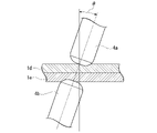
- LME cracks are cracks that occur when the zinc in the galvanized layer melts due to the heat generated during spot welding, the molten zinc invades the grain boundaries of the steel plate structure of the weld, and tensile stress acts on that state. ..
- LME cracking even if one is a cold-rolled steel sheet that has not been galvanized, if the other is a galvanized steel sheet, the zinc melted by the galvanized steel sheet comes into contact with the cold-rolled steel sheet during spot welding. May cause LME cracking. Further, LME cracking occurs remarkably especially when a high-strength TRIP steel sheet (transformation-induced plastic steel sheet) is spot-welded.
- the high-strength TRIP steel sheet is a steel sheet having a higher concentration of C, Si, and Mn than a normal high-strength steel sheet and having excellent energy absorption capacity and press formability by containing retained austenite.
- Hydrogen embrittlement cracking is a phenomenon in which a steel member under high stress under usage conditions suddenly breaks due to hydrogen that has entered the steel from the environment. This phenomenon is also called delayed fracture because of the form of fracture.
- hydrogen embrittlement cracking of a steel sheet is more likely to occur as the tensile strength of the steel sheet increases. It is considered that this is because the higher the tensile strength of the steel sheet, the greater the stress remaining on the steel sheet after forming the part.
- the sensitivity to hydrogen embrittlement cracking is called hydrogen embrittlement resistance.
- hydrogen embrittlement cracking is particularly likely to occur in the bent portion where a large plastic strain is applied. Therefore, when a high-strength steel sheet is used for an automobile member, it is required to improve not only formability such as elongation, bendability, and hole expandability, but also hydrogen embrittlement resistance of the bent portion.
- High-strength steel plates used for vehicle bodies are liable to become brittle due to hydrogen in the steel, and are liable to crack or break at low stress when stress such as bending deformation is applied.
- Patent Document 2 describes high strength with excellent ductility and hole widening property, excellent chemical conversion treatment property, plating adhesion property, fatigue property and hydrogen embrittlement resistance property of bent portion. Steel plates are disclosed.
- Patent Document 2 is excellent in hydrogen embrittlement resistance of the bent portion, but when punched, hydrogen embrittlement may occur at the punched end face. Concerned, it turned out that it may not be possible to meet the demand for higher collision characteristics in recent years.
- the present invention provides a steel sheet having high strength and excellent formability (particularly uniform elongation), collision resistance (particularly punched portion), and LME resistance during spot welding, and a method for manufacturing the same. The purpose is to do.
- the present invention has been made based on the above findings, and the gist thereof is as follows.
- the steel plate according to one aspect of the present invention has a chemical composition of% by mass, C: 0.10 to 0.40%, Si: 0.10 to 1.20%, Al: 0.30 to 1. .50%, Mn: 1.0 to 4.0%, P: 0.0200% or less, S: 0.0200% or less, N: 0.0200% or less, O: 0.0200% or less, Ni: 0 ⁇ 1.00%, Mo: 0 to 0.50%, Cr: 0 to 2.00%, Ti: 0 to 0.100%, B: 0 to 0.0100%, Nb: 0 to 0.10% , V: 0 to 0.50%, Cu: 0 to 0.50%, W: 0 to 0.10%, Ta: 0 to 0.100%, Co: 0 to 0.50%, Mg: 0 to 0.050%, Ca: 0 to 0.0500%, Y: 0 to 0.050%, Zr: 0 to 0.050%, La: 0 to 0.0500%, Ce: 0 to 0.05
- the volume ratio of retained austenite is 3% or more and 20% or less
- the balance is one or two kinds of fresh martensite and tempered martensite
- the aspect ratio is Retained austenite having a thickness of 3.0 or more occupies 80% or more of the total retained austenite in terms of area ratio
- the internal oxide layer having a thickness from the surface of the steel plate of 4.0 ⁇ m or more and the steel plate. It has a decarburized layer having a thickness from the surface of 10 ⁇ m or more and 100 ⁇ m or less, and the amount of diffusible hydrogen contained in the steel plate is 1.00 ppm or less on a mass basis.
- the steel sheet according to the above [1] may have a hot-dip galvanized layer on the surface.
- the steel sheet according to the above [1] may have an alloyed hot-dip galvanized layer on the surface.
- the method for producing a steel sheet according to another aspect of the present invention includes a hot-rolling step of hot-rolling a slab having the chemical composition according to [1] to obtain a hot-rolled steel sheet, and the hot-rolled steel sheet. Is cooled at a cooling rate of 5 ° C./s or higher and wound up at 400 ° C. or lower, and the hot-rolled steel sheet after the winding step is pickled and then 0.5% or more and 20.0%.
- the cold-rolled steel sheet is held at a holding temperature of Ac1 to Ac3 ° C. for 1 second or more and 1000 seconds or less, and the cold-rolled steel sheet after the holding is cooled to 100 to 340 ° C. at an average cooling rate of 4 ° C./s or more.
- the cooled rolled steel sheet is reheated and held at 350 ° C. or higher and 480 ° C. or lower for 80 seconds or longer.
- t -2.4 ⁇ T + 96 (1)
- T: is the average temperature (° C.) when left unattended.
- the cold-rolled steel sheet after the baking step is further subjected to a temperature range of (zinc plating bath temperature ⁇ 40) ° C. to (zinc plating bath temperature +50) ° C. It may have a hot-dip galvanizing step of forming hot-dip galvanizing on the surface of the cold-rolled steel sheet by immersing it in a hot-dip galvanizing bath.
- the method for manufacturing a steel sheet according to the above [5] may further include an alloying step of heating the hot-dip galvanized steel sheet to a temperature range of 300 to 500 ° C. to alloy the plated layer. good.
- the steel sheet according to this embodiment has a predetermined chemical composition described later and has a predetermined chemical composition.
- the volume fractions of ferrite, bainite, and pearlite are 0% or more and 50% or less in total.
- the volume fraction of retained austenite is 3% or more and 20% or less.
- the rest is one or two types of fresh martensite and tempered martensite.
- Retained austenite having an aspect ratio of 3.0 or more accounts for 80% or more of the total retained austenite in terms of area ratio.
- It has an internal oxide layer having a thickness of 4.0 ⁇ m or more from the surface of the steel sheet and a decarburized layer having a thickness of 10 ⁇ m or more and 100 ⁇ m or less from the surface of the steel sheet.
- the amount of diffusible hydrogen contained in the steel sheet is 1.00 ppm or less on a mass basis.
- the metal structure (microstructure) of the steel sheet according to this embodiment will be described.
- the tissue fraction is expressed as a volume fraction
- the unit "%" of the tissue fraction means volume percent unless otherwise specified.
- Those that identify the tissue fraction by image processing consider the area fraction as the volume fraction.
- the metallographic structure of the steel sheet according to the present embodiment represents a metallographic structure at 1/4 part of the plate thickness (position at a depth of 1/4 of the plate thickness in the plate thickness direction from the surface).
- the reason for defining the metal structure of 1/4 part of the plate thickness is that in the plate thickness direction, in the vicinity of the surface and the vicinity of the center of the plate thickness, the microstructure (component) of the steel sheet becomes the other part due to decarburization and Mn segregation, respectively. This is because the metal structure of 1/4 part of the plate thickness may be a typical structure of the steel sheet.
- Bainite is a tissue obtained by holding it at 350 ° C or higher and 450 ° C or lower for a certain period of time after annealing. Bainite is a tissue that contributes to improved elongation because it is soft against martensite. However, in order to obtain the desired high strength, it is necessary to limit the volume fraction as in the case of ferrite.
- Pearlite is a structure that contains hard iron carbide and is the starting point for the generation of voids when expanding holes.
- the volume fractions of ferrite, bainite and pearlite are 50% or less in total.
- the total volume fraction of ferrite, bainite and pearlite may be 40% or less in total. Since ferrite, bainite and pearlite are not essential to obtain the effect of this embodiment, the lower limit thereof is 0%.
- Retained austenite is a tissue that contributes to the improvement of elongation (particularly uniform elongation) by the TRIP effect.
- the volume fraction of retained austenite is set to 3% or more.
- the volume fraction of retained austenite is preferably 5% or more, more preferably 7% or more.
- the volume fraction of retained austenite becomes excessive, the particle size of retained austenite becomes large.
- Retained austenite having such a large particle size becomes coarse and hard martensite after deformation. In this case, it is not preferable because it tends to be a starting point of cracking and the hole expanding property is deteriorated. Therefore, the volume fraction of retained austenite is set to 20% or less.
- the volume fraction of retained austenite is preferably 18% or less, more preferably 16% or less.
- the stability of the retained austenite is enhanced by controlling not only the volume fraction of the retained austenite but also the aspect ratio of the retained austenite. Since the stability of the retained austenite is high, the process-induced transformation to the fresh martensite phase, which is a hard phase, can be suppressed, so that the uniform elongation is improved.
- Fresh martensite and / or tempered martensite The remainder other than the above-mentioned ferrite, bainite, pearlite, and retained austenite is one or two of fresh martensite and tempered martensite. Since fresh martensite is a hard structure with a high dislocation density, it is a structure that contributes to the improvement of tensile strength. Tempering martensite, like fresh martensite, is a collection of lath-shaped crystal grains and is a structure that contributes to the improvement of tensile strength. On the other hand, tempered martensite is a hard structure containing fine iron-based carbides inside due to tempering, unlike fresh martensite.
- Tempering martensite is obtained by tempering fresh martensite produced by cooling after annealing by heat treatment or the like. Considering the volume fractions of ferrite, bainite, pearlite, and retained austenite, the total volume fraction of fresh martensite and tempered martensite is 30 to 97%.
- the volume fraction of retained austenite can be calculated by measuring the diffraction intensity using X-rays.
- the surface of the sample cut out from the steel sheet to the 1/4 depth position of the plate thickness is removed by mechanical polishing and chemical polishing, and MoK ⁇ rays are emitted on the polished surface (1/4 depth position).
- X-ray diffraction was performed using the sample, and the texture of retained austenite was determined from the integrated intensity ratios of the diffraction peaks of the bcc phase (200) and (211) and the fcc phase (200), (220) and (311). Calculate the rate.
- the 5-peak method is used as a general calculation method.
- the volume fraction of fresh martensite is determined by the following procedure. Samples are taken so that the cross section of the plate thickness parallel to the rolling direction of the steel plate is the observation surface.
- the observation surface of the sample is etched with a reperer solution, and the electric field is applied to a region of 100 ⁇ m ⁇ 100 ⁇ m within the range of 1/8 to 3/8 of the plate thickness from the surface centered on the 1/4 depth position of the plate thickness from the surface. It is determined from the obtained secondary electron image by observing with a radiation scanning electron microscope (FE-SEM) at a magnification of 3000 times.
- FE-SEM radiation scanning electron microscope
- the area ratio of the uncorroded area is the total area ratio of fresh martensite and retained austenite.
- the area ratio of this uncorroded area is regarded as the total area ratio of fresh martensite and retained austenite, and the volume ratio of retained austenite measured by the above-mentioned X-ray is subtracted from this total area ratio. Calculate the volume fraction of fresh martensite.
- the volume ratios of ferrite, bainite, pearlite, and tempered martensite can be observed by FE-SEM and determined from the obtained secondary electron image.
- the observation surface shall be a sheet thickness cross section parallel to the rolling direction of the steel sheet. Polishing and night-game etching are performed on the observation surface, and 100 ⁇ m within the range of 1/8 to 3/8 of the plate thickness from the surface centered on the position of 1/4 depth from the surface on the observation surface. A region of ⁇ 100 ⁇ m is observed at a magnification of 3000 times. By leaving a plurality of indentations around the region observed by the above-mentioned repeller corrosion, the same region as the region observed by the repeller corrosion can be confirmed.
- Bainite is a collection of lath-shaped crystal grains that does not contain iron-based carbides with a major axis of 20 nm or more inside, or contains iron-based carbides with a major axis of 20 nm or more inside, and the carbides are a single variant. That is, it belongs to a group of iron-based carbides extending in the same direction.
- the iron-based carbide group elongated in the same direction means that the difference in the elongation direction of the iron-based carbide group is within 5 °.
- Tempering martensite is a collection of lath-shaped crystal grains and contains iron-based carbides with a major axis of 20 nm or more inside, but cementite in the structure has multiple variants. Further, the region where cementite is deposited in a lamellar shape is pearlite. Based on these differences, each tissue is identified and the area ratio is calculated by image processing. Then, in the present embodiment, as described above, the value obtained by calculating the area ratio by image processing is regarded as the volume ratio.
- retained austenite with aspect ratio of 3.0 or more: 80 area% or more of total retained austenite By forming the retained austenite into a needle shape, the stability when subjected to strain is improved. Specifically, retained austenite gradually transforms from grain boundaries to martensite, and distortion occurs with this transformation. As the transformation progresses, the dislocations generated near the grain boundaries move through the grains to the opposite grain boundaries, and the dislocations are accumulated. When the retained austenite is needle-shaped, the distance from the vicinity of the grain boundary where dislocations occur to the grain boundaries where dislocations are accumulated is short.
- the retained austenite is formed into a needle shape by the method described later, but the retained austenite generated without controlling the shape does not have a needle-like structure, and the stability varies in each retained austenite. Therefore, the uniform elongation deteriorates.
- "retained austenite having an aspect ratio of 3.0 or more” is defined as “needle-shaped retained austenite”.
- the retained austenite having an aspect ratio of 3.0 or more is 80% or more of the total retained austenite, the uniform elongation is improved and the hydrogen embrittlement resistance is improved.
- the retained austenite having an aspect ratio of 3.0 or more is preferably 83% or more, more preferably 85% or more of the total retained austenite.
- the upper limit of the ratio of retained austenite having an aspect ratio of 3.0 or more to the total retained austenite is not particularly set, and is ideally 100%.
- the "ratio" referred to here is an area ratio as described later.
- the upper limit of the aspect ratio of the retained austenite that defines the area ratio is not limited, but if the aspect ratio is high, it becomes the starting point of void generation when the residual ⁇ is transformed, and the uniform elongation may decrease. Therefore, the ratio of retained austenite having an aspect ratio of 3.0 to 8.0 is preferably 80% or more.
- the area ratio of the retained austenite having an aspect ratio of 3.0 or more to the total retained austenite is determined by the EBSD analysis method using FE-SEM. Specifically, a sample whose observation surface is a sheet thickness section parallel to the rolling direction of the steel sheet is collected, the observation surface of the sample is polished, the strain-affected layer is removed by electrolytic polishing, and the plate thickness is 1 from the surface. EBSD analysis is performed in a region of 100 ⁇ m ⁇ 100 ⁇ m within the range of 1/8 to 3/8 of the plate thickness from the surface centered on the / 4 depth position, with the measurement step set to 0.05 ⁇ m.
- the magnification of the measurement may be any magnification selected from 1000 to 9000 times, and may be, for example, 3000 times, which is the same as the observation of the SEM-reflected electron image described above.
- Create a retained austenite map from the measured data extract retained austenite with an aspect ratio of 3.0 or more, and obtain the area ratio (area of retained austenite with aspect ratio of 3.0 or more / area of total retained austenite). ..
- the steel sheet according to the present embodiment has an internal oxide layer having a thickness of 4.0 ⁇ m or more from the surface (the internal oxide layer is formed to a depth of at least 4.0 ⁇ m from the surface).
- the internal oxide layer is a layer in which at least a part of the crystal grain boundaries is covered with an oxide of an easily oxidizing element such as Si or Mn. By covering the crystal grain boundaries with the oxide, it is possible to suppress the invasion of the molten metal into the crystal grain boundaries during welding and to suppress the LME cracking during welding. If the thickness of the internal oxide layer is less than 4.0 ⁇ m, the above effect cannot be sufficiently obtained.
- the thickness of the internal oxide layer is set to 4.0 ⁇ m or more.
- the upper limit of the internal oxide layer is preferably 15.0 ⁇ m or less.
- the surface refers to the surface of the base steel sheet (the interface between the plated layer and the base steel sheet).
- the thickness of the internal oxide layer is determined by the following method.
- the plate thickness of the steel plate in the case of a plated steel plate, the plate thickness of the base steel plate
- the position of t / 2 in the plate thickness direction from the surface is defined as the plate thickness center C.
- the Mn concentration distribution is measured by a high-frequency glow discharge emission analyzer (GDS) over a distance of 120 ⁇ m from the surface to the plate thickness center C with the plate thickness cross section parallel to the rolling direction of the steel plate as the measurement surface and the surface of the steel plate as the origin. Measure continuously. Due to the formation of the internal oxide layer, the solid-dissolved Mn around the oxide is deficient and the Mn concentration decreases.
- the Mn concentration is low in the internal oxide layer and increases from the internal oxide layer toward the inside of the plate thickness. , The concentration becomes constant from a certain point. Therefore, the concentration at this constant position is used as the representative concentration inside the steel sheet.
- the position where the Mn concentration becomes 90% of the representative concentration inside the steel sheet is defined as X1, and the distance from the surface to X1 is defined as the thickness of the internal oxide layer. Define.
- a known high frequency GDS analysis method can be used.
- a method is used in which the surface of the steel sheet is made into an Ar atmosphere, a voltage is applied to generate glow plasma, and the surface of the steel sheet is sputtered to analyze in the depth direction. Then, the element contained in the material (steel plate) is identified from the emission spectrum wavelength peculiar to the element emitted by exciting the atom in the glow plasma, and the amount of the element contained in the material is estimated from the emission intensity of the identified element.
- the data in the depth direction can be estimated from the spatter time. Specifically, the spatter time can be converted into the spatter depth by obtaining the relationship between the spatter time and the spatter depth in advance using a standard sample. Therefore, the sputter depth converted from the sputter time can be defined as the depth from the surface of the material. For high frequency GDS analysis, a commercially available analyzer can be used.
- the steel sheet according to the present embodiment has a decarburized layer having a thickness of 10 ⁇ m or more from the surface of the steel sheet (the decarburized layer is formed to a depth of at least 10 ⁇ m from the surface). If the thickness of the decarburized layer is less than 10 ⁇ m, the above effect cannot be sufficiently obtained. On the other hand, if the thickness of the decarburized layer exceeds 100 ⁇ m, the strength is insufficient. Therefore, the thickness of the decarburized layer is 100 ⁇ m or less.
- the thickness of the decarburized layer is determined by the following method.
- the region (excluding the plating layer) on the surface side of the steel sheet is defined as the decarburized layer from the deepest position where the average hardness is 80% or less with respect to the average hardness inside the steel sheet.
- the average hardness inside the steel sheet and the average hardness at each position in the thickness direction of the steel sheet are obtained as follows. A sample is taken with the thickness cross section parallel to the rolling direction of the steel sheet as the observation surface, the observation surface is polished to a mirror surface, and chemical polishing is performed using colloidal silica to remove the processed layer on the surface layer.
- the pushing load is set so that the Vickers indentations do not interfere with each other.
- the pushing load is 20 gf.
- the diagonal length of the indentation is measured using an optical microscope, a scanning electron microscope, or the like, and converted into Vickers hardness (Hv).
- the measurement position is moved by 10 ⁇ m or more in the rolling direction, and the same measurement is performed up to a position with a plate thickness of 1/8 with the starting point as a depth position of 10 ⁇ m from the surface.
- the measurement position is moved by 10 ⁇ m or more in the rolling direction, and the same measurement is performed from the surface to the position of 1/8 of the plate thickness, starting from the position at a depth of 5 ⁇ m from the surface.
- the measurement position is moved by 10 ⁇ m or more in the rolling direction, and the same measurement is performed from the outermost layer to the position of 1/8 thickness with the starting point as the depth position of 10 ⁇ m.
- the Vickers hardness of 5 points is measured at each depth position.
- the reason why the measurement interval is not simply set to 5 ⁇ m pitch is to avoid interference between indentations.
- the average value of the five points at the same depth position is taken as the hardness at the thickness position. By interpolating between each data with a straight line, a hardness profile in the depth direction is obtained.
- the hardness at at least 5 points was measured using a micro-hardness measuring device in the same manner as described above.
- the value obtained by averaging the values is taken as the average hardness inside the steel sheet.
- the region on the surface side of the steel sheet is defined as the decarburized layer from the deepest position where the average hardness is 80% or less with respect to the average hardness inside the steel sheet obtained as described above.
- the decarburized layer defined as described above exists in the region having a thickness of 10 to 100 ⁇ m in the plate thickness direction from the surface.
- a decarburized layer having a hardness of 80% or less of the average hardness inside the steel sheet is present on the surface layer portion of the steel sheet, and the thickness of the decarburized layer is 10 to 100 ⁇ m.
- the amount of diffusible hydrogen in the steel sheet is set to 1.00 ppm or less on a mass basis so that the steel sheet has excellent collision resistance even if it has high strength. If the amount of diffusible hydrogen exceeds 1.00 ppm, the collision resistance is deteriorated.
- the amount of diffusible hydrogen is preferably 0.80 ppm or less.
- the hydrogen embrittlement resistance property may be evaluated by the critical diffusible hydrogen amount, but in the steel plate according to the present embodiment, the diffusible hydrogen amount in the steel plate is controlled from the viewpoint of reducing the hydrogen amount at the time of manufacture. is doing.
- the amount of diffusible hydrogen in the steel plate is measured by a temperature-raising hydrogen analysis method using a gas chromatograph (heating rate: 100 ° C / hour, measured up to 300 ° C), and the amount of hydrogen released from the steel material from room temperature to 200 ° C is measured.
- the amount of diffusible hydrogen is measured by a temperature-raising hydrogen analysis method using a gas chromatograph (heating rate: 100 ° C / hour, measured up to 300 ° C), and the amount of hydrogen released from the steel material from room temperature to 200 ° C is measured. The amount of diffusible hydrogen.
- % related to the component composition means mass%.
- C is an element that secures a predetermined amount of martensite (fresh martensite and tempered martensite) and improves the strength of the steel sheet.
- the C content is preferably 0.12% or more.
- the C content is set to 0.40% or less.
- the C content is preferably 0.35% or less.
- Si 0.10% to 1.20% Si is an element useful for improving the strength of steel sheets by solid solution strengthening. Further, since Si suppresses the formation of cementite, it is an effective element for promoting the concentration of C in austenite and forming retained austenite after annealing. Further, Si has an effect of segregating carbon (C) on the ⁇ grain boundary in the annealing step described later. If the Si content is less than 0.10%, it becomes difficult to obtain the effect of the above action, sufficient uniform elongation cannot be obtained, and hydrogen embrittlement resistance deteriorates, which is not preferable. Therefore, the Si content is set to 0.10% or more. The Si content is preferably 0.50% or more, more preferably 0.60% or more.
- the Si content is 1.20% or less.
- the Si content is preferably 1.10% or less, more preferably 1.00% or less.
- Al 0.30% or more, 1.50% or less
- Al is an element having an action of deoxidizing molten steel. Further, Al is an effective element for promoting the concentration of C in austenite and producing retained austenite after annealing because it suppresses the formation of cementite like Si.
- the Si content is set to the above range in order to improve the LME resistance
- the Al content is set to a relatively high range in order to increase the volume fraction of the residual ⁇ . Specifically, when the Al content is less than 0.30%, these effects cannot be sufficiently obtained, so the Al content is set to 0.30% or more.
- the Al content is preferably 0.40% or more, more preferably 0.50% or more.
- the Al content is 1.50% or less.
- the Al content is preferably 1.40% or less, more preferably 1.30% or less.
- Mn 1.0 to 4.0% Mn has an action of improving the hardenability of steel and is an effective element for obtaining the metallographic structure of the present embodiment.
- the Mn content is preferably 1.3% or more.
- the Mn content is set to 4.0% or less.
- the Mn content is preferably 3.5% or less.
- P 0.0200% or less
- P is an impurity element, which segregates in the central portion of the thickness of the steel sheet to reduce toughness and embrittle the welded portion.
- the P content is preferably 0.0100% or less. The smaller the P content is, the more preferable it is, and it may be 0%. However, if the P content is reduced to less than 0.0001% in the practical steel sheet, the manufacturing cost is significantly increased, which is economically disadvantageous. Therefore, the P content may be 0.0001% or more.
- S 0.0200% or less
- S is an impurity element, which is an element that lowers weldability and lowers manufacturability during casting and hot spreading. Further, S is also an element that forms coarse MnS and causes a decrease in hole expandability. When the S content exceeds 0.0200%, the weldability, the manufacturability, and the hole widening property are significantly reduced. Therefore, the S content is 0.0200% or less. The smaller the S content is, the more preferable it is, and it may be 0%. However, if S is reduced to less than 0.0001% in the practical steel sheet, the manufacturing cost is significantly increased, which is economically disadvantageous. Therefore, the S content may be 0.0001% or more.
- N 0.0200% or less
- N is an element that forms a coarse nitride, reduces bendability and hole widening property, and causes blowholes during welding.
- the N content exceeds 0.0200%, the hole expanding property is lowered and the blow hole is remarkably generated. Therefore, the N content is 0.0200% or less.
- the N content may be 0.0001% or more.
- O 0.0200% or less
- O is an element that forms a coarse oxide, reduces bendability and hole widening property, and causes blowholes during welding.
- the O content exceeds 0.0200%, the hole expanding property is lowered and the blow hole is remarkably generated. Therefore, the O content is 0.0200% or less.
- the O content may be 0.0005% or more.
- the balance excluding the above elements is basically Fe and impurities. Impurities are elements that are allowed to exist within a range that is mixed from the steel raw material and / or in the steelmaking process and does not clearly deteriorate the characteristics of the steel sheet according to the present embodiment.
- the chemical composition of the steel plate according to the present embodiment has Ni: 1.00% or less, Mo: 0.50% or less, Cr: 2.
- Ni 0 to 1.00%
- Ni is an element effective in improving the strength of steel sheets.
- the Ni content may be 0%, but in order to obtain the above effect, the Ni content is preferably 0.001% or more.
- the Ni content is more preferably 0.01% or more.
- the Ni content is set to 1.00% or less.
- Mo 0 to 0.50%
- Mo is an element that contributes to increasing the strength of the steel sheet. This effect can be obtained even in a trace amount.
- the Mo content may be 0%, but in order to obtain the above effect, the Mo content is preferably 0.01% or more.
- the Mo content is set to 0.50% or less.
- Cr 0 to 2.00% Cr is an element that improves the hardenability of steel and contributes to high strength, and is an effective element for obtaining the above-mentioned metallographic structure. Therefore, Cr may be contained.
- the Cr content may be 0%, but in order to sufficiently obtain the above effects, the Cr content is preferably 0.01% or more. On the other hand, even if Cr is excessively contained, the effect of the above action is saturated and it becomes uneconomical. Therefore, the Cr content is set to 2.00% or less.
- Ti 0 to 0.100%
- Ti is an element that contributes to an increase in the strength of a steel sheet by strengthening precipitation, strengthening fine grains by suppressing the growth of ferrite crystal grains, and / or strengthening dislocations by suppressing recrystallization.
- the Ti content may be 0%, but in order to sufficiently obtain the above effects, the Ti content is preferably 0.001% or more. In order to further increase the strength of the steel sheet, the Ti content is more preferably 0.010% or more. On the other hand, when the Ti content exceeds 0.100%, the precipitation of carbonitride increases and the moldability deteriorates. Therefore, the Ti content is set to 0.100% or less.
- B 0 to 0.0100%
- B is an element that suppresses the formation of ferrite and pearlite in the metal structure during the cooling process from the austenite temperature range and promotes the formation of a low temperature transformation structure such as bainite or martensite. Further, B is an element useful for increasing the strength of steel. This effect can be obtained even in a trace amount.
- the B content may be 0%, but in order to obtain the above effect, the B content is preferably 0.0001% or more.
- the B content is 0.0100% or less.
- Nb is an element that contributes to the increase in the strength of the steel sheet by strengthening precipitation, strengthening fine grains by suppressing the growth of ferrite crystal grains, and / or strengthening dislocations by suppressing recrystallization.
- the Nb content may be 0%, but the Nb content is preferably 0.01% or more in order to sufficiently obtain the above effects. In order to further increase the strength of the steel sheet, the Nb content is more preferably 0.05% or more.
- the Nb content is set to 0.10% or less. From the viewpoint of moldability, the Nb content is preferably 0.06% or less.
- V 0 to 0.50%
- V is an element that contributes to the increase in the strength of the steel sheet by strengthening precipitation, strengthening fine grains by suppressing the growth of ferrite crystal grains, and / or strengthening dislocations by suppressing recrystallization.
- the V content may be 0%, but in order to sufficiently obtain the above effect, the V content is preferably 0.01% or more, more preferably 0.02% or more.
- the V content is set to 0.50% or less.
- the V content is preferably 0.40% or less.
- Cu 0 to 0.50%
- the Cu content may be 0%, but in order to obtain the above effect, the Cu content is preferably 0.01% or more.
- the Cu content is set to 0.50% or less.
- W 0 to 0.10% W is an element effective for improving the strength of the steel sheet.
- the W content may be 0%, but in order to obtain the above effect, the W content is preferably 0.01% or more.
- the W content is set to 0.10% or less.
- Ta is also an element effective for improving the strength of the steel sheet.
- the Ta content may be 0%, but in order to obtain the above effect, the Ta content is preferably 0.001% or more.
- the Ta content is set to 0.100% or less.
- the Ta content is preferably 0.020% or less, more preferably 0.010% or less.
- Co 0 to 0.50%
- Co is an element effective for improving the strength of the steel sheet.
- the Co content may be 0%, but in order to obtain the above effect, the Co content is preferably 0.01% or more.
- the Co content is set to 0.50% or less.
- Mg 0 to 0.050%
- Mg is an element that controls the morphology of sulfides and oxides and contributes to the improvement of bend formability of steel sheets. Since this effect can be obtained even in a trace amount, the Mg content may be 0%, but in order to obtain the above effect, the Mg content is preferably 0.0001% or more. On the other hand, if the Mg content is too high, the cold formability may deteriorate due to the formation of coarse inclusions. Therefore, the Mg content is set to 0.050% or less. The Mg content is preferably 0.040% or less.
- Ca 0-0.0500%
- the Ca content may be 0%, but in order to obtain the above effect, the Ca content is preferably 0.0010% or more.
- the Ca content is 0.0500% or less.
- the Ca content is preferably 0.0400% or less, more preferably 0.0300% or less.
- Y 0 to 0.050%
- Y is an element that can control the morphology of sulfide with a small amount.
- the Y content may be 0%, but in order to obtain the above effect, the Y content is preferably 0.001% or more.
- the Y content is set to 0.050% or less.
- the Y content is preferably 0.040% or less.
- Zr 0 to 0.050%
- Zr is an element that can control the morphology of sulfide with a small amount.
- the Zr content may be 0%, but in order to obtain the above effect, the Zr content is preferably 0.001% or more.
- the Zr content is set to 0.050% or less.
- the Zr content is preferably 0.040% or less.
- La 0-0.0500%
- the La content may be 0%, but in order to obtain the above effect, the La content is preferably 0.0010% or more.
- the La content is 0.0500% or less.
- the La content is preferably 0.0400% or less.
- Ce 0 to 0.050%
- Ce is an element that can control the morphology of sulfide with a small amount, and is an element that also contributes to the improvement of LME resistance.
- the Ce content is preferably 0.001% or more.
- the Ce content may be 0.002% or more, 0.003% or more, or 0.005% or more.
- the Ce content is set to 0.050% or less.
- the Ce content may be 0.040% or less, 0.020% or less, or 0.010% or less.
- Sn 0 to 0.05%
- Sn is an element that can be contained in a steel sheet when scrap is used as a raw material for the steel sheet. Sn may be contained because it has an effect of improving corrosion resistance, but it is an element that may cause a decrease in cold formability of a steel sheet due to embrittlement of ferrite. If the Sn content is more than 0.05%, the adverse effect becomes remarkable, so the Sn content is set to 0.05% or less.
- the Sn content is preferably 0.04% or less, and may be 0%. However, reducing the Sn content to less than 0.001% leads to an excessive increase in refining cost, so the Sn content may be 0.001% or more.
- Sb 0 to 0.050% Similar to Sn, Sb is an element that can be contained in a steel sheet when scrap is used as a raw material for the steel sheet. Since Sb has an effect of improving corrosion resistance, it may be contained, but it is an element that may cause embrittlement and decrease in elongation of grain boundaries and decrease in cold formability due to strong segregation at grain boundaries. be. If the Sb content is more than 0.050%, the adverse effect becomes remarkable, so the Sb content is set to 0.050% or less. The Sb content is preferably 0.040% or less, and may be 0%. However, reducing the Sb content to less than 0.001% leads to an excessive increase in refining cost, so the Sb content may be 0.001% or more.
- the As content is preferably 0.040% or less, and may be 0%. However, reducing the As content to less than 0.001% leads to an excessive increase in refining cost, so the As content may be 0.001% or more.
- the chemical composition of the steel sheet according to this embodiment can be obtained by the following method.
- the chemical composition of the above-mentioned steel sheet may be measured by a general chemical composition.
- ICP-AES Inductively Coupled Plasma-Atomic Emission Spectrum
- C and S may be measured by using the combustion-infrared absorption method
- N may be measured by using the inert gas melting-heat conductivity method
- O may be measured by using the inert gas melting-non-dispersive infrared absorption method.
- the plating layer may be removed by mechanical grinding and then the chemical composition may be analyzed.
- a zinc plating layer may be formed on the surface (both sides or one side) of the steel sheet according to the present embodiment.
- the hot-dip galvanized layer may be an alloyed alloyed hot-dip galvanized layer.
- the chemical composition of the hot-dip galvanized layer of the steel sheet according to the present embodiment is not particularly limited, and may be a known plated layer. Further, it is not hindered that the steel sheet according to the present embodiment has another plating (for example, aluminum plating).
- the Fe content in the hot-dip galvanized layer is preferably less than 7.0% by mass.
- the hot-dip galvanized layer is an alloyed alloyed hot-dip galvanized layer
- the Fe content is preferably 6.0% by mass or more. More preferably, it is 7.0% by mass or more.
- the alloyed hot-dip galvanized steel sheet has better weldability than the hot-dip galvanized steel sheet.
- an upper plating layer may be further provided on the zinc plating layer and the zinc plating layer for the purpose of improving coatability, weldability, and the like.
- the zinc-plated steel sheet may be subjected to various treatments such as chromate treatment, phosphate treatment, lubricity improvement treatment, weldability improvement treatment and the like.
- the tensile strength (TS) is targeted to be 980 MPa or more in consideration of the contribution to the improvement of the fuel efficiency of the automobile.
- the upper limit of the tensile strength is not particularly limited, but may be 1310 MPa or less in terms of moldability.
- the uniform elongation (u-El) is targeted to be 7.0% or more from the viewpoint of formability.
- the upper limit of uniform elongation is not particularly limited.
- Tensile strength and uniform elongation are measured by collecting a JIS No. 5 tensile test piece described in JIS Z 2241: 2011 from a steel sheet in a direction perpendicular to the rolling direction and performing a tensile test along JIS Z 2241: 2011. do.
- the steel sheet according to the present embodiment has excellent hydrogen embrittlement resistance at the punched end face, it has excellent collision resistance.
- the tensile strength when a semi-circular punched hole with a diameter of 10 mm is made in the center of both ends of the JIS No. 5 tensile test piece and pulled along JIS Z 2241: 2011 is the center of both ends of the JIS No. 5 tensile test piece.
- the tensile strength is TS2
- R TS1 / TS2
- the value of R is 0. It is preferably .93 or more.
- the steel plate according to the present embodiment is, for example, two steel plates having at least one zinc-plated steel plate at a pressure of 450 kgf (4413 kgm / m /) using a servomotor pressure type single-phase AC spot welder (power supply frequency 50 Hz). While pressurizing in s2), the current value is 6.5 kA, the inclination angle of the electrode is 3 °, there is no upslope, the energization time is 0.4 seconds, and the holding time after energization is 0.1 seconds.
- the steel sheet according to this embodiment can be manufactured by a manufacturing method including the following steps.
- An annealing step of annealing the cold-rolled steel sheet after the hydrogen amount reducing step. t -2.4 ⁇ T + 96 (1)
- T is the average temperature (° C.) when left unattended.
- preferable conditions will be described for each step. Known conditions can be applied to the conditions not described.
- a slab having the above-mentioned chemical composition (the same chemical composition as that of the steel sheet according to the present embodiment) is hot-rolled to obtain a hot-rolled steel sheet.
- the slab to be subjected to hot rolling is not particularly limited as long as it has the above-mentioned chemical composition, and may be a slab produced by a conventional method.
- the slab may be a slab manufactured by a general method such as a continuously cast slab or a thin slab caster.
- hot rolling rough rolling and finish rolling are performed.
- finish rolling the slab after rough rolling is rolled by a plurality of finish rolling mills.
- the heating temperature and holding time of the slab before hot rolling are not particularly limited.
- the plate thickness of the hot-rolled steel sheet obtained by hot rolling is not particularly specified, but if the plate thickness is less than 1.0 mm, the plate may be broken during the annealing process. If the plate thickness is thicker than 6.0 mm, the steel plate is heavy, and even if tension is applied during plate passage, it does not become taut and may meander. Therefore, it is preferably 1.0 to 6.0 mm.
- the hot-rolled steel sheet (hot-rolled steel sheet) as described above has a temperature (rolling) of 400 ° C or lower so that the cooling rate from the hot rolling process end temperature to the winding temperature is always 5 ° C / s or higher. Cool to the taking temperature) and wind up at that temperature.
- the cooling rate minimum cooling rate
- the cooling rate is preferably 10 ° C./s or higher, more preferably 20 ° C./s or higher.
- the upper limit of the cooling rate is not particularly limited, but may be 100 ° C./s or less from the viewpoint of manufacturability. At temperatures below 400 ° C, the cooling rate is not limited.
- the hot-rolled steel sheet after the winding step is pickled and then cold-rolled at a reduction rate of 0.5 to 20.0% to obtain a cold-rolled steel sheet.
- Pickling is a step for removing oxides on the surface of the hot-rolled steel sheet, and may be performed under known conditions. The number of pickling may be one or more.
- the rolling reduction ratio for cold rolling is set to 0.5% or more.
- the reduction rate is preferably 5.0% or more.
- the rolling reduction ratio of cold rolling exceeds 20.0%, the ferrite interface movement is promoted in the heating process of the annealing step, and needle-shaped austenite cannot be obtained.
- the reduction ratio of cold rolling is set to 20.0% or less.
- the rolling reduction of cold rolling is preferably 18.0% or less.
- the cold-rolled steel sheet after the hydrogen content reduction step is bent and bent back at 150 to 400 ° C., and then contains 0.1 to 30.0% by volume of hydrogen and H2O .
- Heating process In the heating process of the annealing step, the steel sheet is bent and bent back with a roll having a radius of 1500 mm or less while the temperature of the steel sheet is 150 to 400 ° C., and the dew point is -20 to 20 ° C., 0.1 to 30.0 volumes. Heat in an atmosphere containing% hydrogen and the balance being nitrogen and impurities. There are two effects by imparting bending back to the steel sheet at 150 to 400 ° C. One is that a sufficient amount of iron-based carbide can be deposited. In this case, the shape of austenite becomes needle-shaped in the heat soaking process described later.
- the lattice spacing inside the steel sheet can be repeatedly changed, and hydrogen on the surface layer can be released to the outside of the steel sheet.
- hydrogen existing inside the steel sheet is also diffused to the surface layer side. If the temperature is less than 150 ° C. when bending back, hydrogen does not diffuse sufficiently, so that the concentration of diffusible hydrogen in the finally obtained steel sheet becomes excessive. Further, when the temperature exceeds 400 ° C., the dislocations imparted by bending and bending back are recovered at a high speed, so that a sufficient amount of iron-based carbide cannot be obtained and needle-shaped austenite cannot be sufficiently obtained.
- the radius of the roll exceeds 1500 mm, it is difficult to efficiently introduce dislocations into the steel sheet structure due to bending-bending back deformation, so the radius of the roll is set to 1500 mm or less.
- the easily oxidizable element is diffused to the surface of the steel sheet. It can prevent and promote internal oxidation. If the amount of hydrogen is less than 0.1% by volume, the oxide film existing on the surface of the steel sheet cannot be sufficiently reduced, and an oxide film is formed on the steel sheet. Therefore, the chemical conversion treatment property and the plating adhesion of the steel sheet obtained after the heat treatment are lowered.
- the amount of hydrogen ( H2 content) in the atmosphere is set to 0.1% or more and 30.0% by volume or less.
- the dew point of the atmosphere is less than ⁇ 20 ° C.
- external oxidation of Si and Mn on the surface layer of the steel sheet occurs, and internal oxidation and decarburization reaction become insufficient.
- the LME resistance and the collision resistance are deteriorated.
- the dew point is more than 20 ° C., an oxide film is formed on the steel sheet to deteriorate the chemical conversion treatment property and the plating adhesion, and the decarburization reaction proceeds excessively.
- Annealing furnaces are roughly divided into three areas: pre-tropical, heated zone and level tropical.
- the atmosphere in the heating zone is the above condition. Atmospheric control is possible even in pre-tropics and average tropics.
- Heat soaking process In the heat soaking process, the cold-rolled steel sheet after the heating process is heated in the temperature range of Ac1 to Ac3 for 1 to 1000 seconds. By soaking under such conditions, needle-shaped austenite is generated along the lath of tempered martensite.
- the specific soaking temperature can be appropriately adjusted based on the Ac1 point (° C.) and the Ac3 point (° C.) represented by the following formulas, taking into consideration the ratio of the desired metal structure.
- Ac1 723-10.7 x Mn-16.9 x Ni + 29.1 x Si + 16.9 x Cr + 290 x As + 6.38 x W ...
- the soaking temperature exceeds Ac3 points, the structure during heat soaking becomes an austenite monophasic structure, and the morphology of the hard structure (low temperature transformation structure) which is the source of the needle-like structure is lost. Therefore, needle-shaped austenite cannot be obtained. Further, if the soaking time is more than 1000 seconds, the productivity is lowered.
- the heat equalization time in the heat equalization process may be set to 300 seconds or less from the viewpoint of suppressing the coarsening of ferrite and austenite during heat equalization.
- the temperature of the steel sheet in the heat soaking process does not have to be constant. If a desired structure ratio can be obtained, the temperature of the steel sheet in the heat soaking step may change within the temperature range of Ac1 to Ac3.
- the cold-rolled steel sheet after the soaking step is cooled to a temperature range of 100 to 340 ° C. so that the average cooling rate is 4 ° C./s or more for the subsequent holding process.
- the average cooling rate is less than 4 ° C./s, ferrite transformation cannot be suppressed.
- the cooling shutdown temperature is less than 100 ° C., the martensite fraction is high.
- the cooling shutdown temperature exceeds 340 ° C., the ferrite, bainite, and pearlite fractions become high, and it becomes difficult to obtain a desired structure.
- the holding process in order to reduce the amount of hydrogen in the steel sheet while increasing the stability of austenite, the cold-rolled steel sheet after the cooling process is reheated to a temperature range of 350 to 480 ° C, and in that temperature range for 80 seconds or more. Hold. If the retention time is less than 80 seconds, carbon is not sufficiently concentrated in the untransformed austenite, and hydrogen cannot be released to the outside of the steel sheet. By setting the holding time in the above temperature range to 80 seconds or more, the carbon concentration in austenite can be increased, and a desired amount of retained austenite can be secured after final cooling. In order to obtain the above effect stably, the holding time is preferably 100 seconds or more.
- the holding time may be 1000 seconds or less because the productivity is lowered if the holding time is excessively long.
- the holding temperature is set to 350 ° C. or higher. It is preferably 380 ° C. or higher.
- the holding temperature is set to 480 ° C. or lower. It is preferably 450 ° C. or lower.
- the conditions for cooling the cold-rolled steel sheet after the holding process to room temperature are not limited, but in order to obtain a stable and desired metal structure, the cold-rolled steel sheet after the holding process has an average cooling rate down to the Ms point or less. It may be cooled to 2 ° C./s or higher.
- the method for manufacturing a steel sheet according to the present embodiment further includes a hot-dip galvanizing step for forming plating on the surface of the cold-rolled steel sheet during the cooling process after annealing, during the holding process, or after the holding process. May be good. Further, after the hot-dip galvanizing step, an alloying step of alloying the plating layer may be further provided.
- the method of hot-dip galvanizing and the method of alloying are not particularly limited, and a conventional method can be used.
- a method of hot-dip galvanizing for example, in the middle of the cooling process, cooling is stopped in a temperature range of (zinc plating bath temperature -40) ° C to (zinc plating bath temperature +50) ° C, and the hot dip galvanizing is controlled in this temperature range to melt.
- Examples thereof include a method of forming hot-dip galvanizing by immersing in a zinc plating bath.
- an alloying method for example, a method of alloying hot dip galvanizing in a temperature range of 300 to 500 ° C. can be mentioned.
- a slab having the chemical composition shown in Table 1 was cast.
- the cast slab was heated to the temperature shown in Table 2 and then hot-rolled to a thickness of 1.0 to 6.0 mm.
- the hot-rolled steel sheet was cooled under the conditions shown in Table 2 and wound up, and then cold-rolled under the conditions shown in Table 2 to obtain a cold-rolled steel sheet.
- These cold-rolled steel sheets were left in the air under the conditions shown in Table 3 to reduce the amount of hydrogen.
- annealing was performed under the conditions shown in Tables 3 and 4.
- An example of bending-bending back was performed on a roll having a radius of roll diameter of 1100 mm in a temperature range of 150 to 400 ° C.
- plating was performed by controlling the temperature in the temperature range of (zinc plating bath temperature ⁇ 40) ° C. to (zinc plating bath temperature +50) ° C. and then immersing in a hot-dip galvanizing bath.
- the steel sheet was heated to a temperature range of 300 to 500 ° C. to alloy the plating layer.
- GI is an example of hot-dip galvanizing
- GA is an example of alloyed hot-dip galvanizing.
- a test piece for SEM observation is collected from the obtained steel sheet (annealed steel sheet or steel sheet plated after annealing), and after polishing the vertical cross section parallel to the rolling direction, the plate thickness is 1 as described above.
- the metallographic structure at the / 4 position was observed, and the area ratio of each structure (ferrite, bainite, pearlite, balance (fresh martensite and / or annealed martensite)) was measured by image processing, and this was used as the volume ratio. ..
- X-ray diffraction was performed in the same manner as described above to determine the volume fraction of retained austenite. The volume fraction of each tissue is shown in Table 5.
- the area ratio of the retained austenite having an aspect ratio of 3.0 or more in the total retained austenite was obtained by the EBSD analysis method using FE-SEM as described above. The results are shown in Table 5.
- the thickness of the decarburized layer and the thickness of the internal oxide layer were measured as described above.
- the amount of diffusible hydrogen contained in the steel was measured as described above. The results are shown in Table 5.
- TS tensile strength
- u-El uniform elongation
- collision resistance assuming punching collision resistance assuming punching
- LME resistance of spot welds are evaluated by the following methods. did.
- collision resistance The collision resistance characteristics were evaluated by the range of R values shown in the following formula.
- a semi-circular punched hole with a diameter of 10 mm was created at the center of both ends of the JIS No. 5 tensile test piece under the conditions of a punch diameter of 10 mm and a punching clearance of 12 ⁇ 2%, and the tensile strength when pulled along JISZ 2241: 2011.
- Example No. 1 A 50 mm ⁇ 80 mm test piece was collected from the obtained steel sheet. Further, a slab having the chemical composition of A in Table 1 was cast, and after applying the production conditions of Example No. 1, it was immersed in a hot-dip galvanized bath to produce a hot-dip galvanized steel sheet (mate material). A 50 mm ⁇ 80 mm test piece was collected from the manufactured steel sheet (mate material). A steel plate as a mating material was superposed on the test pieces collected from each of the steel plates of Example Nos. 1 to 37, and two steel plates were spot welded as shown in FIG. Specifically, a hot-dip galvanized steel sheet, which is a mating material, is used as the steel sheet 1d in FIG. Spot welded.
- a servomotor pressurized single-phase AC spot welder (power supply frequency 50 Hz) was used, and while pressurizing at a pressure of 450 kgf (4413 kgm / s 2 ), the current value was 6.5 kA and the inclination angle of the electrodes was ⁇ was set to 3 °, no upslope was used, the energization time was 0.4 seconds, and the holding time after the end of energization was 0.1 seconds.
- the structure of the center of the nugget at the joint of the steel sheets was observed using an optical microscope at a magnification of 200 to 1000 times.
- the tensile strength is a value larger than 980 MPa and the uniform elongation is a value larger than 7.0%.
- the evaluation of the index R of the collision resistance was A or B, and the evaluation of the LME resistance (length of crack after spot welding) was A or B.
- the tensile strength is larger than 980 MPa and the uniform elongation is 7.0% or more.
- the evaluation of the index R of the collision resistance characteristic was A or B, and the evaluation of the crack length after spot welding was A or B.
- any of the chemical composition and the structure is out of the scope of the present invention, and any of the tensile strength, uniform elongation, collision resistance, and LME resistance is inferior. rice field.
- Example No. 17 the minimum cooling rate from the hot rolling process end temperature to the take-up temperature was less than 5 ° C./s. Therefore, the proportion of retained austenite having an aspect ratio of 3.0 or more in the structure after annealing was small, and the amount of diffusible hydrogen contained in the steel was large. As a result, uniform elongation and collision resistance were low.
- Example No. 18 the take-up temperature was higher than 400 ° C. Therefore, the proportion of retained austenite having an aspect ratio of 3.0 or more was small, and the amount of diffusible hydrogen contained in the steel was large. As a result, uniform elongation and collision resistance were low.
- Example No. 17 the minimum cooling rate from the hot rolling process end temperature to the take-up temperature was less than 5 ° C./s. Therefore, the proportion of retained austenite having an aspect ratio of 3.0 or more in the structure after annealing was small, and the amount of diffusible hydrogen contained in the steel was large. As a result, uniform elongation and collision resistance
- Example No. 19 since the cold rolling ratio was less than 0.5% in the cold rolling process, the proportion of retained austenite having an aspect ratio of 3.0 or more in the texture after annealing was small and contained in the steel. The amount of diffusible hydrogen was large. As a result, uniform elongation and collision resistance were low.
- Example No. 20 since the cold rolling ratio was more than 20.0% in the cold rolling process, the proportion of retained austenite having an aspect ratio of 3.0 or more in the texture after annealing was small and contained in the steel. The amount of diffusible hydrogen was large. As a result, uniform elongation and collision resistance were low. In Example No.
- Example No. 21 the diffusible hydrogen amount could not be sufficiently reduced because the time left in the atmosphere in the hydrogen amount reduction step was less than -2.4 ⁇ T + 96 (time: hour). As a result, the collision resistance was low.
- Example No. 22 since bending and bending back were not applied in the heating process of the annealing step, the proportion of retained austenite having an aspect ratio of 3.0 or more in the structure after annealing was small, and the diffusivity contained in the steel was small. There was a lot of hydrogen. As a result, uniform elongation and collision resistance were low. In Example No. 23, since the dew point was less than ⁇ 20 ° C.
- Example No. 24 the dew point was more than 20 ° C. in the heating process of the annealing step, so that the thickness of the decarburized layer became excessive. As a result, the tensile strength was low.
- Example No. 25 since the holding temperature was less than Ac1 point in the soaking process of the annealing step, the total area fraction of ferrite, bainite, and pearlite exceeded 50%, and the volume fraction of retained austenite was 0%. .. As a result, the tensile strength was low. In Example No.
- Example No. 26 since the holding temperature was more than Ac3 points in the soaking process of the annealing step, the volume fraction of retained austenite became small, and the proportion of retained austenite having an aspect ratio of 3.0 or more became small. rice field. As a result, the collision resistance and uniform elongation were low.
- Example No. 27 since the average cooling rate was less than 4 ° C./s in the cooling process of the annealing step, the total area ratio of ferrite, bainite, and pearlite exceeded 50%. As a result, the tensile strength was low.
- Example No. 28 since the holding temperature was less than 350 ° C. in the holding process of the annealing step, the retained austenite was not stabilized and the volume fraction of the retained austenite became small.
- Example No. 29 since the holding temperature was over 480 ° C. in the holding process of the annealing step, the total area ratio of ferrite, bainite, and pearlite exceeded 50%. As a result, the tensile strength was low. In Example No. 30, since the holding time was less than 80 seconds in the holding process of the annealing step, the retained austenite was not stabilized and the volume fraction of the retained austenite became small. As a result, the uniform elongation was low.
- Example No. 31 the C content was less than 0.10%, so that the tensile strength was low. In addition, the volume fraction of retained austenite was insufficient. As a result, the uniform elongation was low.
- Example No. 32 the C content was more than 0.40%, so that the LME resistance was lowered.
- Example No. 33 the Si content was less than 0.10%, so that the volume fraction of retained austenite was insufficient. As a result, the uniform elongation was low.
- Example No. 34 the Si content was more than 1.20%, so that the LME resistance was lowered.
- Example No. 35 the volume fraction of retained austenite was insufficient because the Al content was less than 0.30%.
- Example No. 36 the Mn content was less than 1.0%, so that the total area ratio of ferrite, bainite, and pearlite exceeded 50%. As a result, the tensile strength was low.
- Example No. 37 the cold rolling ratio in the cold rolling step was less than 0.5%, and the hydrogen content reduction step was not performed, so that the residual structure after annealing had an aspect ratio of 3.0 or more. The proportion of austenite was small and the amount of diffusible hydrogen contained in the steel was large. As a result, uniform elongation and collision resistance were low.
Abstract
Description
本願は、2021年01月07日に、日本に出願された特願2021-001682号に基づき優先権を主張し、その内容をここに援用する。 The present invention relates to a steel sheet and a method for manufacturing the same.
The present application claims priority based on Japanese Patent Application No. 2021-001682 filed in Japan on January 07, 2021, and the contents thereof are incorporated herein by reference.
また、LME割れは、特に、高強度TRIP鋼板(変態誘起塑性鋼板)をスポット溶接した際に、顕著に発生する。高強度TRIP鋼板とは、通常の高強度鋼板よりもC、Si、Mn濃度が高く、残留オーステナイトを含むことにより、優れたエネルギー吸収能およびプレス成形性を有する鋼板のことである。 However, for the assembly of the car body and / or parts, galvanized steel sheets (hot-dip galvanized steel sheets, electrogalvanized steel sheets or alloyed hot-dip galvanized steel sheets) are spot-welded to each other, or cold-rolled steel sheets and galvanized steel sheets are spot-welded. When welding is performed, cracks called liquid metal embrittlement (LME) cracks may occur in the spot welded portion. LME cracks are cracks that occur when the zinc in the galvanized layer melts due to the heat generated during spot welding, the molten zinc invades the grain boundaries of the steel plate structure of the weld, and tensile stress acts on that state. .. For LME cracking, even if one is a cold-rolled steel sheet that has not been galvanized, if the other is a galvanized steel sheet, the zinc melted by the galvanized steel sheet comes into contact with the cold-rolled steel sheet during spot welding. May cause LME cracking.
Further, LME cracking occurs remarkably especially when a high-strength TRIP steel sheet (transformation-induced plastic steel sheet) is spot-welded. The high-strength TRIP steel sheet is a steel sheet having a higher concentration of C, Si, and Mn than a normal high-strength steel sheet and having excellent energy absorption capacity and press formability by containing retained austenite.
以上を鑑み、本発明は、高強度を有するとともに、成形性(特に均一伸び)、耐衝突特性(特に打ち抜き加工部)、及びスポット溶接時の耐LME性に優れた鋼板及びその製造方法を提供することを目的とする。 As described above, conventionally, a steel sheet having high strength and excellent formability, collision resistance (particularly collision resistance in a punched portion), and LME resistance during spot welding has not been disclosed.
In view of the above, the present invention provides a steel sheet having high strength and excellent formability (particularly uniform elongation), collision resistance (particularly punched portion), and LME resistance during spot welding, and a method for manufacturing the same. The purpose is to do.
[2]上記[1]に記載の鋼板では、前記表面に溶融亜鉛めっき層を有してもよい。
[3]上記[1]に記載の鋼板では、前記表面に合金化溶融亜鉛めっき層を有してもよい。
[4]本発明の別の態様に係る鋼板の製造方法は、[1]に記載の前記化学組成を有するスラブを熱間圧延し、熱延鋼板とする熱間圧延工程と、前記熱延鋼板を5℃/s以上の冷却速度で冷却し、400℃以下で巻き取る巻取工程と、前記巻取工程後の前記熱延鋼板を、酸洗した後に、0.5%以上20.0%以下の圧下率で冷間圧延して冷延鋼板とする冷間圧延工程と、前記冷延鋼板を、1時間以上かつ下記式(1)で表されるt時間以上の間、大気中で放置する水素量低減工程と、前記水素量低減工程後の前記冷延鋼板を焼鈍する焼鈍工程と、を有し、前記焼鈍工程は、前記冷延鋼板に対して、150~400℃において鋼板へ曲げ曲げ戻しを付与し、前記冷延鋼板を、露点が-20℃から20℃の、0.1~30.0体積%の水素を含み残部が窒素および不純物である雰囲気で加熱し、前記加熱後の前記冷延鋼板を、Ac1~Ac3℃の保持温度で1秒以上1000秒以下保持し、前記保持後の前記冷延鋼板を、平均冷却速度4℃/s以上で100~340℃まで冷却し、前記冷却後の前記冷延鋼板を、再加熱し、350℃以上480℃以下で80秒以上保持する。
t=-2.4×T+96 (1)
ここで、T:放置時の平均気温(℃)である。
[5]上記[4]に記載の鋼板の製造方法では、さらに、前記焼鈍工程後の前記冷延鋼板を、(亜鉛めっき浴温度-40)℃~(亜鉛めっき浴温度+50)℃の温度域に制御した後、溶融亜鉛めっき浴に浸漬することにより、前記冷延鋼板の表面に溶融亜鉛めっきを形成する溶融亜鉛めっき工程を有してもよい。
[6]上記[5]に記載の鋼板の製造方法では、さらに、前記溶融亜鉛めっき鋼板を、300~500℃の温度域に加熱してめっき層を合金化する合金化工程を有してもよい。 [1] The steel plate according to one aspect of the present invention has a chemical composition of% by mass, C: 0.10 to 0.40%, Si: 0.10 to 1.20%, Al: 0.30 to 1. .50%, Mn: 1.0 to 4.0%, P: 0.0200% or less, S: 0.0200% or less, N: 0.0200% or less, O: 0.0200% or less, Ni: 0 ~ 1.00%, Mo: 0 to 0.50%, Cr: 0 to 2.00%, Ti: 0 to 0.100%, B: 0 to 0.0100%, Nb: 0 to 0.10% , V: 0 to 0.50%, Cu: 0 to 0.50%, W: 0 to 0.10%, Ta: 0 to 0.100%, Co: 0 to 0.50%, Mg: 0 to 0.050%, Ca: 0 to 0.0500%, Y: 0 to 0.050%, Zr: 0 to 0.050%, La: 0 to 0.0500%, Ce: 0 to 0.050%, It contains Sn: 0 to 0.05%, Sb: 0 to 0.050%, As: 0 to 0.050%, the balance is Fe and impurities, and the volume ratio of ferrite, bainite, and pearlite in the metal structure. Is 0% or more and 50% or less in total, the volume ratio of retained austenite is 3% or more and 20% or less, and the balance is one or two kinds of fresh martensite and tempered martensite, and the aspect ratio is Retained austenite having a thickness of 3.0 or more occupies 80% or more of the total retained austenite in terms of area ratio, and the internal oxide layer having a thickness from the surface of the steel plate of 4.0 μm or more and the steel plate. It has a decarburized layer having a thickness from the surface of 10 μm or more and 100 μm or less, and the amount of diffusible hydrogen contained in the steel plate is 1.00 ppm or less on a mass basis.
[2] The steel sheet according to the above [1] may have a hot-dip galvanized layer on the surface.
[3] The steel sheet according to the above [1] may have an alloyed hot-dip galvanized layer on the surface.
[4] The method for producing a steel sheet according to another aspect of the present invention includes a hot-rolling step of hot-rolling a slab having the chemical composition according to [1] to obtain a hot-rolled steel sheet, and the hot-rolled steel sheet. Is cooled at a cooling rate of 5 ° C./s or higher and wound up at 400 ° C. or lower, and the hot-rolled steel sheet after the winding step is pickled and then 0.5% or more and 20.0%. The cold-rolled step of cold-rolling at the following rolling ratio to obtain a cold-rolled steel sheet, and the cold-rolled steel sheet are left in the air for 1 hour or more and t hours or more represented by the following formula (1). It has a hydrogen amount reducing step and an annealing step of annealing the cold-rolled steel sheet after the hydrogen amount reducing step, and the annealing step bends the cold-rolled steel sheet into a steel sheet at 150 to 400 ° C. After bending back, the cold-rolled steel sheet was heated in an atmosphere having a dew point of −20 ° C. to 20 ° C., containing 0.1 to 30.0% by volume of hydrogen, and the balance being nitrogen and impurities. The cold-rolled steel sheet is held at a holding temperature of Ac1 to Ac3 ° C. for 1 second or more and 1000 seconds or less, and the cold-rolled steel sheet after the holding is cooled to 100 to 340 ° C. at an average cooling rate of 4 ° C./s or more. The cooled rolled steel sheet is reheated and held at 350 ° C. or higher and 480 ° C. or lower for 80 seconds or longer.
t = -2.4 × T + 96 (1)
Here, T: is the average temperature (° C.) when left unattended.
[5] In the method for manufacturing a steel sheet according to the above [4], the cold-rolled steel sheet after the baking step is further subjected to a temperature range of (zinc plating bath temperature −40) ° C. to (zinc plating bath temperature +50) ° C. It may have a hot-dip galvanizing step of forming hot-dip galvanizing on the surface of the cold-rolled steel sheet by immersing it in a hot-dip galvanizing bath.
[6] The method for manufacturing a steel sheet according to the above [5] may further include an alloying step of heating the hot-dip galvanized steel sheet to a temperature range of 300 to 500 ° C. to alloy the plated layer. good.
本実施形態に係る鋼板は、後述する所定の化学組成を有し、
金属組織において、
フェライト、ベイナイト、パーライトの体積率が合計で0%以上、50%以下であり、
残留オーステナイトの体積率が3%以上、20%以下であり、
残部がフレッシュマルテンサイト及び焼き戻しマルテンサイトの1種または2種であり、
アスペクト比が3.0以上である残留オーステナイトが、面積率で、前記全残留オーステナイトのうちの80%以上を占め、
前記鋼板の表面からの厚みが4.0μm以上である内部酸化層と、前記鋼板の前記表面からの厚みが10μm以上100μm以下である脱炭層とを有し、
前記鋼板中に含まれる拡散性水素量が、質量基準で1.00ppm以下である。 Hereinafter, a steel sheet according to an embodiment of the present invention (steel sheet according to the present embodiment) and a method for manufacturing the same will be described.
The steel sheet according to this embodiment has a predetermined chemical composition described later and has a predetermined chemical composition.
In the metallographic structure
The volume fractions of ferrite, bainite, and pearlite are 0% or more and 50% or less in total.
The volume fraction of retained austenite is 3% or more and 20% or less.
The rest is one or two types of fresh martensite and tempered martensite.
Retained austenite having an aspect ratio of 3.0 or more accounts for 80% or more of the total retained austenite in terms of area ratio.
It has an internal oxide layer having a thickness of 4.0 μm or more from the surface of the steel sheet and a decarburized layer having a thickness of 10 μm or more and 100 μm or less from the surface of the steel sheet.
The amount of diffusible hydrogen contained in the steel sheet is 1.00 ppm or less on a mass basis.
まず、本実施形態に係る鋼板の金属組織(ミクロ組織)について説明する。以下、組織分率は体積率で表示するので、組織分率の単位「%」は断りがない限り体積%を意味する。画像処理により組織分率を同定するものは、面積率を体積率とみなす。本実施形態に係る鋼板の金属組織は、特に断りが無い限りは板厚1/4部(表面から板厚方向に、板厚の1/4の深さ位置)における金属組織を表す。板厚1/4部の金属組織を規定する理由は、板厚方向において、表面近傍及び板厚中心近傍では、それぞれ、脱炭及びMn偏析により鋼板のミクロ組織(構成要素)がその他の部分と大きく異なる場合があるからであり、板厚1/4部の金属組織が、鋼板の代表的な組織となるからである。 <Metal structure>
First, the metal structure (microstructure) of the steel sheet according to this embodiment will be described. Hereinafter, since the tissue fraction is expressed as a volume fraction, the unit "%" of the tissue fraction means volume percent unless otherwise specified. Those that identify the tissue fraction by image processing consider the area fraction as the volume fraction. Unless otherwise specified, the metallographic structure of the steel sheet according to the present embodiment represents a metallographic structure at 1/4 part of the plate thickness (position at a depth of 1/4 of the plate thickness in the plate thickness direction from the surface). The reason for defining the metal structure of 1/4 part of the plate thickness is that in the plate thickness direction, in the vicinity of the surface and the vicinity of the center of the plate thickness, the microstructure (component) of the steel sheet becomes the other part due to decarburization and Mn segregation, respectively. This is because the metal structure of 1/4 part of the plate thickness may be a typical structure of the steel sheet.
フェライトは、軟質な組織であるので変形し易く、伸びの向上に寄与する組織である。しかしながら、所望の高強度を得るためには、フェライトの体積率を制限する必要がある。
ベイナイトは焼鈍後に350℃以上、450℃以下に一定時間保持することで得られる組織である。ベイナイトは、マルテンサイトに対して軟質であるので、伸びの向上に寄与する組織である。しかしながら、所望の高強度を得るためには、フェライトと同様に体積率を制限する必要がある。
パーライトは、硬質な鉄炭化物を含み、穴広げ時にボイドの発生の起点となる組織である。
上記の理由から、本実施形態に係る鋼板では、フェライト、ベイナイト及びパーライトの体積率は合計で50%以下とする。強度を高めるためには、フェライト、ベイナイト及びパーライトの合計体積率は、合計で40%以下としても良い。本実施形態の効果を得るためには、フェライト、ベイナイト及びパーライトは必須ではないので、その下限は0%である。 [Ferite, bainite and pearlite: 0-50% in total]
Since ferrite is a soft structure, it is easily deformed and contributes to the improvement of elongation. However, in order to obtain the desired high strength, it is necessary to limit the volume fraction of ferrite.
Bainite is a tissue obtained by holding it at 350 ° C or higher and 450 ° C or lower for a certain period of time after annealing. Bainite is a tissue that contributes to improved elongation because it is soft against martensite. However, in order to obtain the desired high strength, it is necessary to limit the volume fraction as in the case of ferrite.
Pearlite is a structure that contains hard iron carbide and is the starting point for the generation of voids when expanding holes.
For the above reasons, in the steel sheet according to the present embodiment, the volume fractions of ferrite, bainite and pearlite are 50% or less in total. In order to increase the strength, the total volume fraction of ferrite, bainite and pearlite may be 40% or less in total. Since ferrite, bainite and pearlite are not essential to obtain the effect of this embodiment, the lower limit thereof is 0%.
残留オーステナイトは、TRIP効果により、伸び(特に均一伸び)の向上に寄与する組織である。この効果を得るため、残留オーステナイトの体積率は3%以上とする。残留オーステナイトの体積率は、好ましくは5%以上、より好ましくは7%以上である。
一方、残留オーステナイトの体積率が過剰になると、残留オーステナイトの粒径が大きくなる。このような粒径の大きな残留オーステナイトは、変形後に粗大かつ硬質なマルテンサイトとなる。この場合、割れの起点となりやすくなり、穴広げ性が劣化するため好ましくない。このため、残留オーステナイトの体積率は20%以下とする。残留オーステナイトの体積率は、好ましくは18%以下、より好ましくは16%以下である。 [Residual austenite: 3-20%]
Retained austenite is a tissue that contributes to the improvement of elongation (particularly uniform elongation) by the TRIP effect. In order to obtain this effect, the volume fraction of retained austenite is set to 3% or more. The volume fraction of retained austenite is preferably 5% or more, more preferably 7% or more.
On the other hand, when the volume fraction of retained austenite becomes excessive, the particle size of retained austenite becomes large. Retained austenite having such a large particle size becomes coarse and hard martensite after deformation. In this case, it is not preferable because it tends to be a starting point of cracking and the hole expanding property is deteriorated. Therefore, the volume fraction of retained austenite is set to 20% or less. The volume fraction of retained austenite is preferably 18% or less, more preferably 16% or less.
上述したフェライト、ベイナイト、パーライト、残留オーステナイト以外の残部は、フレッシュマルテンサイト及び焼き戻しマルテンサイトの1種または2種である。
フレッシュマルテンサイトは、転位密度が高く硬質な組織であるので、引張強さの向上に寄与する組織である。
焼き戻しマルテンサイトは、フレッシュマルテンサイトと同様に、ラス状の結晶粒の集合であり、引張強さの向上に寄与する組織である。一方で、焼き戻しマルテンサイトは、フレッシュマルテンサイトとは異なり、焼き戻しにより内部に微細な鉄系炭化物を含む硬質な組織である。
焼き戻しマルテンサイトは、焼鈍後の冷却等により生成したフレッシュマルテンサイトを熱処理等により焼き戻すことで得られる。
フェライト、ベイナイト、パーライト、残留オーステナイトの体積率を考慮すると、フレッシュマルテンサイトと焼き戻しマルテンサイトとの合計体積率は、30~97%となる。 [Remaining: Fresh martensite and / or tempered martensite]
The remainder other than the above-mentioned ferrite, bainite, pearlite, and retained austenite is one or two of fresh martensite and tempered martensite.
Since fresh martensite is a hard structure with a high dislocation density, it is a structure that contributes to the improvement of tensile strength.
Tempering martensite, like fresh martensite, is a collection of lath-shaped crystal grains and is a structure that contributes to the improvement of tensile strength. On the other hand, tempered martensite is a hard structure containing fine iron-based carbides inside due to tempering, unlike fresh martensite.
Tempering martensite is obtained by tempering fresh martensite produced by cooling after annealing by heat treatment or the like.
Considering the volume fractions of ferrite, bainite, pearlite, and retained austenite, the total volume fraction of fresh martensite and tempered martensite is 30 to 97%.
X線を用いる測定では、鋼板から切り出した試料の表面から板厚の1/4深さ位置までを機械研磨及び化学研磨により除去し、研磨面(1/4深さ位置)において、MoKα線を用いて、X線回折を行い、bcc相の(200)、(211)、及び、fcc相の(200)、(220)、(311)の回折ピークの積分強度比から、残留オーステナイトの組織分率を算出する。一般的な算出方法として5ピーク法が利用される。 The volume fraction of retained austenite can be calculated by measuring the diffraction intensity using X-rays.
In the measurement using X-rays, the surface of the sample cut out from the steel sheet to the 1/4 depth position of the plate thickness is removed by mechanical polishing and chemical polishing, and MoKα rays are emitted on the polished surface (1/4 depth position). X-ray diffraction was performed using the sample, and the texture of retained austenite was determined from the integrated intensity ratios of the diffraction peaks of the bcc phase (200) and (211) and the fcc phase (200), (220) and (311). Calculate the rate. The 5-peak method is used as a general calculation method.
鋼板の圧延方向に平行な板厚断面が観察面となるように試料を採取する。試料の観察面をレペラ液でエッチングし、表面から板厚の1/4深さ位置を中心とする表面から板厚の1/8~3/8の範囲内の100μm×100μmの領域について、電界放射型走査電子顕微鏡(FE-SEM)を用いて3000倍の倍率で観察し、得られた二次電子像から決定する。レペラ腐食では、フレッシュマルテンサイトおよび残留オーステナイトは腐食されないため、腐食されていない領域の面積率は、フレッシュマルテンサイト及び残留オーステナイトの合計面積率である。この腐食されていない領域の面積率をフレッシュマルテンサイト及び残留オーステナイトの合計面積率であるとみなし、この合計面積率から、上述したX線で測定した残留オーステナイトの体積率を引算することで、フレッシュマルテンサイトの体積率を算出する。 The volume fraction of fresh martensite is determined by the following procedure.
Samples are taken so that the cross section of the plate thickness parallel to the rolling direction of the steel plate is the observation surface. The observation surface of the sample is etched with a reperer solution, and the electric field is applied to a region of 100 μm × 100 μm within the range of 1/8 to 3/8 of the plate thickness from the surface centered on the 1/4 depth position of the plate thickness from the surface. It is determined from the obtained secondary electron image by observing with a radiation scanning electron microscope (FE-SEM) at a magnification of 3000 times. Since fresh martensite and retained austenite are not corroded by repera corrosion, the area ratio of the uncorroded area is the total area ratio of fresh martensite and retained austenite. The area ratio of this uncorroded area is regarded as the total area ratio of fresh martensite and retained austenite, and the volume ratio of retained austenite measured by the above-mentioned X-ray is subtracted from this total area ratio. Calculate the volume fraction of fresh martensite.
観察において、フェライトは、粒界の内側が均一なコントラストで写る。ベイナイトは、ラス状の結晶粒の集合であり、内部に長径20nm以上の鉄系炭化物を含まないもの、または、内部に長径20nm以上の鉄系炭化物を含み、その炭化物が、単一のバリアント、すなわち、同一方向に伸長した鉄系炭化物群に属する。ここで、同一方向に伸長した鉄系炭化物群とは、鉄系炭化物群の伸長方向の差異が5°以内であるものをいう。焼き戻しマルテンサイトは、ラス状の結晶粒の集合であり、内部に長径20nm以上の鉄系炭化物を含むが、組織内のセメンタイトが複数のバリアントを有する。また、セメンタイトがラメラ状に析出している領域がパーライトである。これらの違いに基づいて、各組織を同定し、画像処理によって面積率を算出する。そして、本実施形態では、前述のように、画像処理により面積率を算出した値を体積率とみなす。 The volume ratios of ferrite, bainite, pearlite, and tempered martensite can be observed by FE-SEM and determined from the obtained secondary electron image. The observation surface shall be a sheet thickness cross section parallel to the rolling direction of the steel sheet. Polishing and night-game etching are performed on the observation surface, and 100 μm within the range of 1/8 to 3/8 of the plate thickness from the surface centered on the position of 1/4 depth from the surface on the observation surface. A region of × 100 μm is observed at a magnification of 3000 times. By leaving a plurality of indentations around the region observed by the above-mentioned repeller corrosion, the same region as the region observed by the repeller corrosion can be confirmed.
In observation, ferrite appears with a uniform contrast inside the grain boundaries. Bainite is a collection of lath-shaped crystal grains that does not contain iron-based carbides with a major axis of 20 nm or more inside, or contains iron-based carbides with a major axis of 20 nm or more inside, and the carbides are a single variant. That is, it belongs to a group of iron-based carbides extending in the same direction. Here, the iron-based carbide group elongated in the same direction means that the difference in the elongation direction of the iron-based carbide group is within 5 °. Tempering martensite is a collection of lath-shaped crystal grains and contains iron-based carbides with a major axis of 20 nm or more inside, but cementite in the structure has multiple variants. Further, the region where cementite is deposited in a lamellar shape is pearlite. Based on these differences, each tissue is identified and the area ratio is calculated by image processing. Then, in the present embodiment, as described above, the value obtained by calculating the area ratio by image processing is regarded as the volume ratio.
残留オーステナイトは、針状化させることにより、歪を受けたときの安定性が向上する。具体的には、残留オーステナイトは、粒界から段階的にマルテンサイトに変態し、この変態に伴い歪が生じる。変態が進行すると、粒界近傍で生じた転位は、粒内を通って反対側の粒界へ移動し、転位が蓄積される。残留オーステナイトが針状の場合、転位が生じる粒界近傍から転位が蓄積される粒界までの距離が近い。そのため、蓄積した転位と新たに生じる転位との間に斥力が生じ、マルテンサイト変態により生じる歪が許容されない。以上の機構でマルテンサイト変態が阻害されるため、残留オーステナイトの安定性が向上する。
本実施形態に係る鋼板では、後述する方法で残留オーステナイトを針状としているが、形状の制御がなされずに生成する残留オーステナイトは、針状組織にならず、それぞれの残留オーステナイトにおいて安定性にばらつきがあるため、均一伸びが悪化する。
さらに、オーステナイト内部には水素が残存しやすいが、針状化したオーステナイトは、塊状オーステナイトに比べ表面積が大きいため、後述の保持過程において、オーステナイト内部の水素拡散が促進される。これによって、鋼板中の拡散性水素量を低減することができる。
本実施形態では「アスペクト比が3.0以上である残留オーステナイト」を「針状化した残留オーステナイト」と定義する。アスペクト比が3.0以上である残留オーステナイトが、全残留オーステナイトのうちの80%以上であることにより、均一伸びが向上するとともに、耐水素脆化特性が向上する。アスペクト比が3.0以上である残留オーステナイトは、好ましくは全残留オーステナイトのうちの83%以上であり、より好ましくは85%以上である。全残留オーステナイトに占めるアスペクト比が3.0以上である残留オーステナイトの割合の上限は特に定められず、理想的には100%である。ここで言う「割合」は、後述するように面積率である。
面積率を規定する残留オーステナイトのアスペクト比の上限は限定されないが、アスペクト比が高い場合は残留γが変態した際にボイドの発生起点となり、均一伸びが低下する可能性がある。そのため好ましくは、アスペクト比が3.0~8.0の残留オーステナイトの割合が80%以上である。 [Ratio of retained austenite with aspect ratio of 3.0 or more: 80 area% or more of total retained austenite]
By forming the retained austenite into a needle shape, the stability when subjected to strain is improved. Specifically, retained austenite gradually transforms from grain boundaries to martensite, and distortion occurs with this transformation. As the transformation progresses, the dislocations generated near the grain boundaries move through the grains to the opposite grain boundaries, and the dislocations are accumulated. When the retained austenite is needle-shaped, the distance from the vicinity of the grain boundary where dislocations occur to the grain boundaries where dislocations are accumulated is short. Therefore, a repulsive force is generated between the accumulated dislocations and the newly generated dislocations, and the strain caused by the martensitic transformation is not allowed. Since the martensitic transformation is inhibited by the above mechanism, the stability of retained austenite is improved.
In the steel sheet according to the present embodiment, the retained austenite is formed into a needle shape by the method described later, but the retained austenite generated without controlling the shape does not have a needle-like structure, and the stability varies in each retained austenite. Therefore, the uniform elongation deteriorates.
Further, hydrogen tends to remain inside the austenite, but since the needle-shaped austenite has a larger surface area than the massive austenite, hydrogen diffusion inside the austenite is promoted in the holding process described later. This makes it possible to reduce the amount of diffusible hydrogen in the steel sheet.
In the present embodiment, "retained austenite having an aspect ratio of 3.0 or more" is defined as "needle-shaped retained austenite". When the retained austenite having an aspect ratio of 3.0 or more is 80% or more of the total retained austenite, the uniform elongation is improved and the hydrogen embrittlement resistance is improved. The retained austenite having an aspect ratio of 3.0 or more is preferably 83% or more, more preferably 85% or more of the total retained austenite. The upper limit of the ratio of retained austenite having an aspect ratio of 3.0 or more to the total retained austenite is not particularly set, and is ideally 100%. The "ratio" referred to here is an area ratio as described later.
The upper limit of the aspect ratio of the retained austenite that defines the area ratio is not limited, but if the aspect ratio is high, it becomes the starting point of void generation when the residual γ is transformed, and the uniform elongation may decrease. Therefore, the ratio of retained austenite having an aspect ratio of 3.0 to 8.0 is preferably 80% or more.
具体的には、鋼板の圧延方向に平行な板厚断面を観察面とする試料を採取し、試料の観察面を研磨した後、電解研磨によってひずみ影響層を除去し、表面から板厚の1/4深さ位置を中心とする表面から板厚の1/8~3/8の範囲内の100μm×100μmの領域を、測定ステップを0.05μmとして、EBSD解析を行う。測定の倍率は1000~9000倍のうち任意の倍率を選択し、例えば前述のSEM-反射電子像の観察と同じ3000倍としてもよい。測定後のデータから残留オーステナイトマップを作成し、アスペクト比が3.0以上の残留オーステナイトを抽出して面積率(アスペクト比が3.0以上の残留オーステナイトの面積/全残留オーステナイトの面積)を求める。 The area ratio of the retained austenite having an aspect ratio of 3.0 or more to the total retained austenite is determined by the EBSD analysis method using FE-SEM.
Specifically, a sample whose observation surface is a sheet thickness section parallel to the rolling direction of the steel sheet is collected, the observation surface of the sample is polished, the strain-affected layer is removed by electrolytic polishing, and the plate thickness is 1 from the surface. EBSD analysis is performed in a region of 100 μm × 100 μm within the range of 1/8 to 3/8 of the plate thickness from the surface centered on the / 4 depth position, with the measurement step set to 0.05 μm. The magnification of the measurement may be any magnification selected from 1000 to 9000 times, and may be, for example, 3000 times, which is the same as the observation of the SEM-reflected electron image described above. Create a retained austenite map from the measured data, extract retained austenite with an aspect ratio of 3.0 or more, and obtain the area ratio (area of retained austenite with aspect ratio of 3.0 or more / area of total retained austenite). ..
本実施形態に係る鋼板は、表面からの厚みが4.0μm以上である内部酸化層を有する(表面から少なくとも4.0μmの深さまで、内部酸化層が形成されている)。内部酸化層とは、結晶粒界の少なくとも一部がSi、Mn等の易酸化性元素の酸化物によって被覆された層のことである。結晶粒界が酸化物によって被覆されることで、溶接時に溶融金属の結晶粒界への侵入を抑制するとともに、溶接中のLME割れを抑制することが可能になる。内部酸化層の厚みが4.0μm未満であると、上記効果が十分に得られない。そのため、内部酸化層の厚みを4.0μm以上とする。
一方、内部酸化層の厚みが厚すぎると、均一伸びが低下する。よって、内部酸化層の上限は15.0μm以下とすることが好ましい。
ただし、めっき鋼板の場合、表面とは、母材鋼板の表面(めっき層と母材鋼板との界面)を指す。 [Internal oxide layer thickness: 4.0 μm or more from the surface]
The steel sheet according to the present embodiment has an internal oxide layer having a thickness of 4.0 μm or more from the surface (the internal oxide layer is formed to a depth of at least 4.0 μm from the surface). The internal oxide layer is a layer in which at least a part of the crystal grain boundaries is covered with an oxide of an easily oxidizing element such as Si or Mn. By covering the crystal grain boundaries with the oxide, it is possible to suppress the invasion of the molten metal into the crystal grain boundaries during welding and to suppress the LME cracking during welding. If the thickness of the internal oxide layer is less than 4.0 μm, the above effect cannot be sufficiently obtained. Therefore, the thickness of the internal oxide layer is set to 4.0 μm or more.
On the other hand, if the thickness of the internal oxide layer is too thick, the uniform elongation is lowered. Therefore, the upper limit of the internal oxide layer is preferably 15.0 μm or less.
However, in the case of a plated steel sheet, the surface refers to the surface of the base steel sheet (the interface between the plated layer and the base steel sheet).
鋼板の板厚(めっき鋼板の場合には母材鋼板の板厚)をtとしたとき、表面から板厚方向にt/2の位置を板厚中心Cとする。鋼板の圧延方向に平行な板厚断面を測定面として、鋼板の表面を原点として表面から板厚中心Cへ向かって120μmの距離にわたって、Mnの濃度分布を高周波グロー放電発光分析装置(GDS)によって連続的に測定する。内部酸化層の形成によって、酸化物周辺の固溶Mnが欠乏して、Mn濃度が低下するので、Mn濃度は、内部酸化層では低く、内部酸化層から板厚内部に向かって増加していき、あるところから一定の濃度となる。そのため、この一定となった位置の濃度を鋼板内部の代表濃度とする。内部酸化層から板厚内部に向かってMn濃度が増加していくとき、Mn濃度が鋼板内部の代表濃度の90%となる位置をX1とし、表面からX1までの距離を内部酸化層の厚みと定義する。
高周波グロー放電分析法で分析する場合には、公知の高周波GDS分析法を用いることができる。具体的には、鋼板の表面をAr雰囲気にし、電圧をかけてグロープラズマを発生させた状態で、鋼板表面をスパッタリングさせながら深さ方向に分析する方法を用いる。そして、グロープラズマ中で原子が励起されて発せられる元素特有の発光スペクトル波長から、材料(鋼板)に含まれる元素を同定し、同定した元素の発光強度から材料に含まれる元素の量を見積もる。深さ方向のデータは、スパッタ時間から見積もることができる。具体的には、予め標準サンプルを用いてスパッタ時間とスパッタ深さとの関係を求めておくことで、スパッタ時間をスパッタ深さに変換できる。したがって、スパッタ時間から変換したスパッタ深さを、材料の表面からの深さと定義できる。高周波GDS分析では、市販の分析装置を用いることができる。 The thickness of the internal oxide layer is determined by the following method.
When the plate thickness of the steel plate (in the case of a plated steel plate, the plate thickness of the base steel plate) is t, the position of t / 2 in the plate thickness direction from the surface is defined as the plate thickness center C. The Mn concentration distribution is measured by a high-frequency glow discharge emission analyzer (GDS) over a distance of 120 μm from the surface to the plate thickness center C with the plate thickness cross section parallel to the rolling direction of the steel plate as the measurement surface and the surface of the steel plate as the origin. Measure continuously. Due to the formation of the internal oxide layer, the solid-dissolved Mn around the oxide is deficient and the Mn concentration decreases. Therefore, the Mn concentration is low in the internal oxide layer and increases from the internal oxide layer toward the inside of the plate thickness. , The concentration becomes constant from a certain point. Therefore, the concentration at this constant position is used as the representative concentration inside the steel sheet. When the Mn concentration increases from the internal oxide layer toward the inside of the plate thickness, the position where the Mn concentration becomes 90% of the representative concentration inside the steel sheet is defined as X1, and the distance from the surface to X1 is defined as the thickness of the internal oxide layer. Define.
When analyzing by the high frequency glow discharge analysis method, a known high frequency GDS analysis method can be used. Specifically, a method is used in which the surface of the steel sheet is made into an Ar atmosphere, a voltage is applied to generate glow plasma, and the surface of the steel sheet is sputtered to analyze in the depth direction. Then, the element contained in the material (steel plate) is identified from the emission spectrum wavelength peculiar to the element emitted by exciting the atom in the glow plasma, and the amount of the element contained in the material is estimated from the emission intensity of the identified element. The data in the depth direction can be estimated from the spatter time. Specifically, the spatter time can be converted into the spatter depth by obtaining the relationship between the spatter time and the spatter depth in advance using a standard sample. Therefore, the sputter depth converted from the sputter time can be defined as the depth from the surface of the material. For high frequency GDS analysis, a commercially available analyzer can be used.
加工後の曲げ性を改善するためには、鋼板の表層を軟質化することが重要な要件の一つである。鋼板の表層を軟質化する手段として、鋼板の表層に脱炭層を設けることが考えられる。
また、鋼板の表層に脱炭層が存在することにより、曲げ後の耐水素脆化特性に優れる。脱炭層が存在することよって曲げ後の耐水素脆化特性が優れる詳細な機構は明らかでないが、脱炭により表層の組織における残留オーステナイト量が低減することで、曲げ加工時に加工誘起変態して生成するフレッシュマルテンサイト量が低減し、耐水素脆化特性が向上することが考えられる。
本実施形態に係る鋼板では、上記効果を得るため、鋼板の表面からの厚みが10μm以上である脱炭層を有する(表面から少なくとも10μmの深さまで、脱炭層が形成されている)。脱炭層の厚みが、10μm未満では、上記効果が十分に得られない。一方、脱炭層の厚みが、100μm超であると、強度が不足する。そのため、脱炭層の厚みは100μm以下とする。 [Thickness of decarburized layer: 10 μm or more and 100 μm or less from the surface]
In order to improve the bendability after processing, it is one of the important requirements to soften the surface layer of the steel sheet. As a means for softening the surface layer of the steel sheet, it is conceivable to provide a decarburized layer on the surface layer of the steel sheet.
Further, since the decarburized layer is present on the surface layer of the steel sheet, it is excellent in hydrogen embrittlement resistance after bending. Although the detailed mechanism of excellent hydrogen embrittlement resistance after bending due to the presence of the decarburized layer is not clear, decarburization reduces the amount of retained austenite in the surface structure, resulting in work-induced transformation during bending. It is considered that the amount of fresh martensite is reduced and the hydrogen embrittlement resistance is improved.
In order to obtain the above effect, the steel sheet according to the present embodiment has a decarburized layer having a thickness of 10 μm or more from the surface of the steel sheet (the decarburized layer is formed to a depth of at least 10 μm from the surface). If the thickness of the decarburized layer is less than 10 μm, the above effect cannot be sufficiently obtained. On the other hand, if the thickness of the decarburized layer exceeds 100 μm, the strength is insufficient. Therefore, the thickness of the decarburized layer is 100 μm or less.
本実施形態に係る鋼板では、鋼板内部の平均硬度に対して平均硬度が80%以下である最も深い位置よりも鋼板の表面側の領域(めっき層は除く)を脱炭層と定義する。本実施形態において、鋼板内部の平均硬度および鋼板の厚さ方向の各位置における平均硬度は、以下のようにして求める。
鋼板の圧延方向に平行な板厚断面を観察面として試料を採取し、観察面を研磨して鏡面に仕上げ、さらに表層の加工層を除去するためにコロイダルシリカを用いて化学研磨を行う。得られた試料の観察面について、微小硬度計を用いて、表面(めっき鋼板の場合には母材鋼板とめっき層との界面)から5μmの深さを起点として、表面から板厚の1/8厚さの位置まで、鋼板の厚さ方向に10μmピッチで、頂角136°の四角錐形状のビッカース圧子を押し込む。このとき、押し込み荷重は互いのビッカース圧痕が干渉しないように設定する。たとえば、押し込み荷重20gfである。その後、光学顕微鏡または走査型電子顕微鏡等を用いて、圧痕の対角線長さを測定し、ビッカース硬さ(Hv)に変換する。
次に、測定位置を圧延方向に10μm以上移動し、起点を表面から10μmの深さ位置として板厚1/8厚さの位置まで同様の測定を行う。次に、また測定位置を圧延方向に10μm以上移動し表面から5μmの深さの位置を起点として、表面から板厚の1/8厚さの位置まで、同様の測定を行う。次に、測定位置を圧延方向に10μm以上移動し、起点を最表層から10μm深さ位置として板厚1/8厚さの位置まで同様の測定を行う。これを繰り返すことによって、各深さ位置につき各5点ずつのビッカース硬さを測定する。こうすることにより、事実上、深さ方向に5μmピッチの硬度測定データが得られる。測定間隔を単純に5μmピッチとしないのは、圧痕同士の干渉を避けるためである。同じ深さ位置の5点の平均値を、その厚さ位置での硬さとする。各データ間は直線で補間することにより、深さ方向の硬さプロファイルを得る。
また、同観察面の1/4厚さ位置を中心とする1/8厚~3/8厚の範囲について、少なくとも5点の硬度を、上記と同じ要領で微小硬度測定装置を用いて測定し、値を平均することにより得られた値を、鋼板内部の平均硬度とする。
上記のように求めた鋼板内部の平均硬度に対して、平均硬度が80%以下となる最も深い位置よりも鋼板の表面側の領域を脱炭層とする。 The thickness of the decarburized layer is determined by the following method.
In the steel sheet according to the present embodiment, the region (excluding the plating layer) on the surface side of the steel sheet is defined as the decarburized layer from the deepest position where the average hardness is 80% or less with respect to the average hardness inside the steel sheet. In the present embodiment, the average hardness inside the steel sheet and the average hardness at each position in the thickness direction of the steel sheet are obtained as follows.
A sample is taken with the thickness cross section parallel to the rolling direction of the steel sheet as the observation surface, the observation surface is polished to a mirror surface, and chemical polishing is performed using colloidal silica to remove the processed layer on the surface layer. Regarding the observation surface of the obtained sample, using a microhardness meter, starting from a depth of 5 μm from the surface (in the case of a plated steel sheet, the interface between the base steel sheet and the plated layer), 1 / of the plate thickness from the surface. Push the Vickers indenter in the shape of a square pyramid with an apex angle of 136 ° at a pitch of 10 μm in the thickness direction of the steel sheet to the position of 8 thickness. At this time, the pushing load is set so that the Vickers indentations do not interfere with each other. For example, the pushing load is 20 gf. Then, the diagonal length of the indentation is measured using an optical microscope, a scanning electron microscope, or the like, and converted into Vickers hardness (Hv).
Next, the measurement position is moved by 10 μm or more in the rolling direction, and the same measurement is performed up to a position with a plate thickness of 1/8 with the starting point as a depth position of 10 μm from the surface. Next, the measurement position is moved by 10 μm or more in the rolling direction, and the same measurement is performed from the surface to the position of 1/8 of the plate thickness, starting from the position at a depth of 5 μm from the surface. Next, the measurement position is moved by 10 μm or more in the rolling direction, and the same measurement is performed from the outermost layer to the position of 1/8 thickness with the starting point as the depth position of 10 μm. By repeating this, the Vickers hardness of 5 points is measured at each depth position. By doing so, in effect, hardness measurement data having a pitch of 5 μm in the depth direction can be obtained. The reason why the measurement interval is not simply set to 5 μm pitch is to avoid interference between indentations. The average value of the five points at the same depth position is taken as the hardness at the thickness position. By interpolating between each data with a straight line, a hardness profile in the depth direction is obtained.
Further, in the range of 1/8 thickness to 3/8 thickness centered on the 1/4 thickness position of the observation surface, the hardness at at least 5 points was measured using a micro-hardness measuring device in the same manner as described above. , The value obtained by averaging the values is taken as the average hardness inside the steel sheet.
The region on the surface side of the steel sheet is defined as the decarburized layer from the deepest position where the average hardness is 80% or less with respect to the average hardness inside the steel sheet obtained as described above.
鋼板中の拡散性水素量が少ないほど、耐衝突特性に優れる。本実施形態に係る鋼板では、高強度であっても、耐衝突特性に優れるよう、鋼板中の拡散性水素量を、質量基準で1.00ppm以下とする。拡散性水素量が1.00ppm超では耐衝突特性が低下する。拡散性水素量は、好ましくは0.80ppm以下である。
耐水素脆化特性とは、限界拡散性水素量で評価されることもあるが、本実施形態に係る鋼板では、製造時の水素量を減少させる観点で、鋼板中の拡散性水素量を制御している。 [Amount of diffusible hydrogen contained in steel sheet: 1.00 ppm or less]
The smaller the amount of diffusible hydrogen in the steel sheet, the better the collision resistance. In the steel sheet according to the present embodiment, the amount of diffusible hydrogen in the steel sheet is set to 1.00 ppm or less on a mass basis so that the steel sheet has excellent collision resistance even if it has high strength. If the amount of diffusible hydrogen exceeds 1.00 ppm, the collision resistance is deteriorated. The amount of diffusible hydrogen is preferably 0.80 ppm or less.
The hydrogen embrittlement resistance property may be evaluated by the critical diffusible hydrogen amount, but in the steel plate according to the present embodiment, the diffusible hydrogen amount in the steel plate is controlled from the viewpoint of reducing the hydrogen amount at the time of manufacture. is doing.
C:0.10~0.40%
Cは、所定量のマルテンサイト(フレッシュマルテンサイト及び焼き戻しマルテンサイト)を確保し、鋼板の強度を向上させる元素である。C含有量が0.10%以上であると、所定量のマルテンサイトを得ることができ、所望の引張強さを確保することができる。C含有量は好ましくは0.12%以上である。
一方、C含有が0.40%を超えると、溶接性や耐LME性が劣化するとともに穴広げ性が劣化する。また耐水素脆性も劣化する。そのため、C含有量は0.40%以下とする。C含有量は好ましくは0.35%以下である。 <Chemical composition>
C: 0.10 to 0.40%
C is an element that secures a predetermined amount of martensite (fresh martensite and tempered martensite) and improves the strength of the steel sheet. When the C content is 0.10% or more, a predetermined amount of martensite can be obtained, and a desired tensile strength can be secured. The C content is preferably 0.12% or more.
On the other hand, if the C content exceeds 0.40%, the weldability and LME resistance deteriorate and the hole widening property deteriorates. The hydrogen embrittlement resistance also deteriorates. Therefore, the C content is set to 0.40% or less. The C content is preferably 0.35% or less.
Siは固溶強化により鋼板の強度を向上させるのに有用な元素である。また、Siはセメンタイトの生成を抑制するので、オーステナイト中へのCの濃化を促進させて、焼鈍後に残留オーステナイトを生成させるのに有効な元素である。また、Siは、後述する焼鈍工程においてγ粒界上に炭素(C)を偏析させる効果を有する。Si含有量が0.10%未満では上記作用による効果を得ることが困難となり、十分な均一伸びが得られない上に耐水素脆性が劣化するため好ましくない。したがって、Si含有量は0.10%以上とする。Si含有量は、好ましくは0.50%以上、より好ましくは0.60%以上である。
一方、Si含有量が1.20%超であると、溶接時にLME割れが生じ易くなる上、化成処理性およびめっき性が著しく劣化する。したがって、Si含有量は1.20%以下とする。Si含有量は、好ましくは1.10%以下、より好ましくは1.00%以下である。 Si: 0.10% to 1.20%
Si is an element useful for improving the strength of steel sheets by solid solution strengthening. Further, since Si suppresses the formation of cementite, it is an effective element for promoting the concentration of C in austenite and forming retained austenite after annealing. Further, Si has an effect of segregating carbon (C) on the γ grain boundary in the annealing step described later. If the Si content is less than 0.10%, it becomes difficult to obtain the effect of the above action, sufficient uniform elongation cannot be obtained, and hydrogen embrittlement resistance deteriorates, which is not preferable. Therefore, the Si content is set to 0.10% or more. The Si content is preferably 0.50% or more, more preferably 0.60% or more.
On the other hand, when the Si content is more than 1.20%, LME cracking is likely to occur at the time of welding, and the chemical conversion treatment property and the plating property are significantly deteriorated. Therefore, the Si content is 1.20% or less. The Si content is preferably 1.10% or less, more preferably 1.00% or less.
Alは、溶鋼を脱酸する作用を有する元素である。またAlは、Siと同様にセメンタイトの生成を抑制するので、オーステナイト中へのCの濃化を促進させて、焼鈍後に残留オーステナイトを生成させるのに有効な元素である。本実施形態に係る鋼板では、耐LME性の向上のため、Si含有量を上述の範囲とした上で、残留γの体積率を上げるため、Al含有量を比較的高い範囲とする。具体的には、Al含有量が0.30%未満の場合にはこれらの効果が十分に得られないので、Al含有量は0.30%以上とする。Al含有量は、好ましくは0.40%以上、より好ましくは0.50%以上である。
一方、Al含有量が高すぎると、粗大なAl酸化物が生成されて鋼板の加工性が低下する。また、Al含有量が高いと鋳造性が悪化する。したがって、Al含有量は1.50%以下とする。Al含有量は、好ましくは1.40%以下、より好ましくは1.30%以下である。 Al: 0.30% or more, 1.50% or less Al is an element having an action of deoxidizing molten steel. Further, Al is an effective element for promoting the concentration of C in austenite and producing retained austenite after annealing because it suppresses the formation of cementite like Si. In the steel sheet according to the present embodiment, the Si content is set to the above range in order to improve the LME resistance, and the Al content is set to a relatively high range in order to increase the volume fraction of the residual γ. Specifically, when the Al content is less than 0.30%, these effects cannot be sufficiently obtained, so the Al content is set to 0.30% or more. The Al content is preferably 0.40% or more, more preferably 0.50% or more.
On the other hand, if the Al content is too high, coarse Al oxide is generated and the workability of the steel sheet is deteriorated. Further, if the Al content is high, the castability deteriorates. Therefore, the Al content is 1.50% or less. The Al content is preferably 1.40% or less, more preferably 1.30% or less.
Mnは、鋼の焼入れ性を向上させる作用を有し、本実施形態の金属組織を得るのに有効な元素である。Mn含有量を1.0%以上とすることで、所望の金属組織を得ることできる。Mn含有量は、好ましくは1.3%以上である。
一方、Mn含有量が過剰になると、Mnの偏析により焼入れ性向上の効果が低下する上、素材コストが上昇する。そのため、Mn含有量は4.0%以下とする。Mn含有量は、好ましくは3.5%以下である。 Mn: 1.0 to 4.0%
Mn has an action of improving the hardenability of steel and is an effective element for obtaining the metallographic structure of the present embodiment. By setting the Mn content to 1.0% or more, a desired metal structure can be obtained. The Mn content is preferably 1.3% or more.
On the other hand, when the Mn content becomes excessive, the effect of improving hardenability is reduced due to segregation of Mn, and the material cost is increased. Therefore, the Mn content is set to 4.0% or less. The Mn content is preferably 3.5% or less.
Pは、不純物元素であり、鋼板の板厚中央部に偏析して靭性を低下させ、また、溶接部を脆化させる元素である。P含有量が0.0200%を超えると、溶接部強度や穴広げ性が著しく低下する。そのため、P含有量は0.0200%以下とする。P含有量は、好ましくは0.0100%以下である。
P含有量は、少ないほど好ましく、0%でもよいが、実用鋼板でP含有量を0.0001%未満に低減すると、製造コストが大幅に上昇し、経済的に不利になる。そのため、P含有量を0.0001%以上としてもよい。 P: 0.0200% or less P is an impurity element, which segregates in the central portion of the thickness of the steel sheet to reduce toughness and embrittle the welded portion. When the P content exceeds 0.0200%, the strength of the welded portion and the hole expandability are significantly reduced. Therefore, the P content is 0.0200% or less. The P content is preferably 0.0100% or less.
The smaller the P content is, the more preferable it is, and it may be 0%. However, if the P content is reduced to less than 0.0001% in the practical steel sheet, the manufacturing cost is significantly increased, which is economically disadvantageous. Therefore, the P content may be 0.0001% or more.
Sは、不純物元素であり、溶接性を低下させ、また、鋳造時と熱延時の製造性を低下させる元素である。また、Sは、粗大なMnSを形成して、穴広げ性の低下の原因となる元素でもある。S含有量が0.0200%を超えると、溶接性の低下、製造性の低下、及び、穴広げ性の低下が顕著になる。そのため、S含有量は0.0200%以下とする。
S含有量は、少ないほど好ましく、0%でもよいが、実用鋼板でSを0.0001%未満に低減すると、製造コストが大幅に上昇し、経済的に不利になる。そのため、S含有量を0.0001%以上としてもよい。 S: 0.0200% or less S is an impurity element, which is an element that lowers weldability and lowers manufacturability during casting and hot spreading. Further, S is also an element that forms coarse MnS and causes a decrease in hole expandability. When the S content exceeds 0.0200%, the weldability, the manufacturability, and the hole widening property are significantly reduced. Therefore, the S content is 0.0200% or less.
The smaller the S content is, the more preferable it is, and it may be 0%. However, if S is reduced to less than 0.0001% in the practical steel sheet, the manufacturing cost is significantly increased, which is economically disadvantageous. Therefore, the S content may be 0.0001% or more.
Nは、粗大な窒化物を形成し、曲げ性や穴広げ性を低下させ、また、溶接時のブローホールの発生原因となる元素である。N含有量が0.0200%を超えると、穴広げ性の低下や、ブローホールの発生が顕著となる。そのため、N含有量は0.0200%以下とする。
N含有量は、少ないほど好ましく、0%でもよいが、実用鋼板でN含有量を0.0001%未満に低減すると、製造コストが大幅に上昇し、経済的に不利になる。そのため、N含有量を0.0001%以上としてもよい。 N: 0.0200% or less N is an element that forms a coarse nitride, reduces bendability and hole widening property, and causes blowholes during welding. When the N content exceeds 0.0200%, the hole expanding property is lowered and the blow hole is remarkably generated. Therefore, the N content is 0.0200% or less.
The smaller the N content is, the more preferable it is, and 0% may be used. However, if the N content is reduced to less than 0.0001% in the practical steel sheet, the manufacturing cost is significantly increased, which is economically disadvantageous. Therefore, the N content may be 0.0001% or more.
Oは、粗大な酸化物を形成し、曲げ性や穴広げ性を低下させ、また、溶接時のブローホールの発生原因となる元素である。O含有量が0.0200%を超えると、穴広げ性の低下や、ブローホールの発生が顕著となる。そのため、O含有量は0.0200%以下とする。
O含有量は、少ないほど好ましく、0%でもよいが、実用鋼板でOを0.0005%未満に低減すると、製造コストが大幅に上昇し、経済的に不利になる。そのため、O含有量を0.0005%以上としてもよい。 O: 0.0200% or less O is an element that forms a coarse oxide, reduces bendability and hole widening property, and causes blowholes during welding. When the O content exceeds 0.0200%, the hole expanding property is lowered and the blow hole is remarkably generated. Therefore, the O content is 0.0200% or less.
The smaller the O content is, the more preferable it is, and 0% may be used. However, if O is reduced to less than 0.0005% in a practical steel sheet, the manufacturing cost is significantly increased, which is economically disadvantageous. Therefore, the O content may be 0.0005% or more.
一方で、本実施形態に係る鋼板の化学組成は、各種特性の向上を目的として、Feの一部に代えて、Ni:1.00%以下、Mo:0.50%以下、Cr:2.00%以下、Ti:0.100%以下、B:0.0100%以下、Nb:0.10%以下、V:0.50%以下、Cu:0.50%以下、W:0.10%以下、Ta:0.100%以下、Co:0.50%以下、Mg:0.050%以下、Ca:0.0500%以下、Y:0.050%以下、Zr:0.050%以下、La:0.0500%以下、Ce:0.050%以下、Sn:0.05%以下、Sb:0.050%以下、As:0.050%以下からなる群から選択される1種または2種以上を含有してもよい。これらの元素は含有しなくてもよいので下限は0%である。また、上記の範囲であれば、これらの元素が不純物として含有されていても本実施形態に係る鋼板の効果を阻害しない。 In the chemical composition of the steel sheet according to the present embodiment, the balance excluding the above elements is basically Fe and impurities. Impurities are elements that are allowed to exist within a range that is mixed from the steel raw material and / or in the steelmaking process and does not clearly deteriorate the characteristics of the steel sheet according to the present embodiment.
On the other hand, the chemical composition of the steel plate according to the present embodiment has Ni: 1.00% or less, Mo: 0.50% or less, Cr: 2. 00% or less, Ti: 0.100% or less, B: 0.0100% or less, Nb: 0.10% or less, V: 0.50% or less, Cu: 0.50% or less, W: 0.10% Below, Ta: 0.100% or less, Co: 0.50% or less, Mg: 0.050% or less, Ca: 0.0500% or less, Y: 0.050% or less, Zr: 0.050% or less, One or 2 selected from the group consisting of La: 0.0500% or less, Ce: 0.050% or less, Sn: 0.05% or less, Sb: 0.050% or less, As: 0.050% or less. It may contain more than a seed. Since these elements do not have to be contained, the lower limit is 0%. Further, within the above range, even if these elements are contained as impurities, the effect of the steel sheet according to the present embodiment is not impaired.
Niは、鋼板の強度の向上に有効な元素である。Ni含有量は0%でも良いが、上記効果を得るためには、Ni含有量が0.001%以上であることが好ましい。Ni含有量は、より好ましくは0.01%以上である。
一方、Ni含有量が多すぎると、鋼板の伸びが低下して成形性が低下する虞がある。このため、Ni含有量は1.00%以下とする。 Ni: 0 to 1.00%
Ni is an element effective in improving the strength of steel sheets. The Ni content may be 0%, but in order to obtain the above effect, the Ni content is preferably 0.001% or more. The Ni content is more preferably 0.01% or more.
On the other hand, if the Ni content is too high, the elongation of the steel sheet may decrease and the formability may decrease. Therefore, the Ni content is set to 1.00% or less.
Moは、Crと同様に鋼板の高強度化に寄与する元素である。この効果は微量であっても得ることができる。Mo含有量は0%でも良いが、上記効果を得るためには、Mo含有量は、0.01%以上であることが好ましい。
一方、Mo含有量が0.50%を超えると、粗大なMo炭化物が形成され、鋼板の冷間成形性が低下する虞がある。このため、Mo含有量は0.50%以下とする。 Mo: 0 to 0.50%
Like Cr, Mo is an element that contributes to increasing the strength of the steel sheet. This effect can be obtained even in a trace amount. The Mo content may be 0%, but in order to obtain the above effect, the Mo content is preferably 0.01% or more.
On the other hand, if the Mo content exceeds 0.50%, coarse Mo carbides may be formed and the cold formability of the steel sheet may be deteriorated. Therefore, the Mo content is set to 0.50% or less.
Crは、鋼の焼入れ性を向上させ、高強度化に寄与する元素であり、上記の金属組織を得るのに有効な元素である。したがって、Crを含有させてもよい。Cr含有量は0%でもよいが、上記の効果を十分に得るためには、Cr含有量を0.01%以上とすることが好ましい。
一方、Crを過剰に含有させても上記作用による効果が飽和する上、不経済となる。したがって、Cr含有量は2.00%以下とする。 Cr: 0 to 2.00%
Cr is an element that improves the hardenability of steel and contributes to high strength, and is an effective element for obtaining the above-mentioned metallographic structure. Therefore, Cr may be contained. The Cr content may be 0%, but in order to sufficiently obtain the above effects, the Cr content is preferably 0.01% or more.
On the other hand, even if Cr is excessively contained, the effect of the above action is saturated and it becomes uneconomical. Therefore, the Cr content is set to 2.00% or less.
Tiは、析出強化、フェライト結晶粒の成長抑制による細粒強化、および/または再結晶の抑制を通じた転位強化によって、鋼板の強度上昇に寄与する元素である。Ti含有量は0%でもよいが、上記効果を十分に得るためには、Ti含有量は0.001%以上であることが好ましい。鋼板のより一層の高強度化のためには、Ti含有量は0.010%以上であることがより好ましい。
一方、Ti含有量が0.100%を超えると、炭窒化物の析出が多くなって成形性が劣化する。このため、Ti含有量は0.100%以下とする。 Ti: 0 to 0.100%
Ti is an element that contributes to an increase in the strength of a steel sheet by strengthening precipitation, strengthening fine grains by suppressing the growth of ferrite crystal grains, and / or strengthening dislocations by suppressing recrystallization. The Ti content may be 0%, but in order to sufficiently obtain the above effects, the Ti content is preferably 0.001% or more. In order to further increase the strength of the steel sheet, the Ti content is more preferably 0.010% or more.
On the other hand, when the Ti content exceeds 0.100%, the precipitation of carbonitride increases and the moldability deteriorates. Therefore, the Ti content is set to 0.100% or less.
Bは、オーステナイト温度域からの冷却過程において、金属組織におけるフェライト及びパーライトの生成を抑え、ベイナイト又はマルテンサイト等の低温変態組織の生成を促す元素である。また、Bは、鋼の高強度化に有益な元素である。この効果は微量であっても得ることができる。B含有量は0%でも良いが、上記効果を得るためには、B含有量を0.0001%以上とすることが好ましい。
一方、B含有量が多すぎると、粗大なB酸化物が生成され、当該B酸化物がプレス成形時にボイドの発生起点となり、鋼板の成形性が低下する虞がある。このため、B含有量は0.0100%以下とする。 B: 0 to 0.0100%
B is an element that suppresses the formation of ferrite and pearlite in the metal structure during the cooling process from the austenite temperature range and promotes the formation of a low temperature transformation structure such as bainite or martensite. Further, B is an element useful for increasing the strength of steel. This effect can be obtained even in a trace amount. The B content may be 0%, but in order to obtain the above effect, the B content is preferably 0.0001% or more.
On the other hand, if the B content is too large, a coarse B oxide is generated, and the B oxide becomes a starting point for generating voids during press forming, which may reduce the formability of the steel sheet. Therefore, the B content is 0.0100% or less.
Nbは、析出強化、フェライト結晶粒の成長抑制による細粒強化、および/または再結晶の抑制を通じた転位強化により、鋼板の強度上昇に寄与する元素である。Nb含有量は0%でもよいが、上記効果を十分に得るには、Nb含有量は0.01%以上であることが好ましい。鋼板のより一層の高強度化のためには、Nb含有量は0.05%以上であることがより好ましい。
一方、Nb含有量が0.10%を超えると、炭窒化物の析出が多くなって成形性が劣化する。このため、Nb含有量は0.10%以下とする。成形性の観点から、Nb含有量は0.06%以下であることが好ましい。 Nb: 0 to 0.10%
Nb is an element that contributes to the increase in the strength of the steel sheet by strengthening precipitation, strengthening fine grains by suppressing the growth of ferrite crystal grains, and / or strengthening dislocations by suppressing recrystallization. The Nb content may be 0%, but the Nb content is preferably 0.01% or more in order to sufficiently obtain the above effects. In order to further increase the strength of the steel sheet, the Nb content is more preferably 0.05% or more.
On the other hand, when the Nb content exceeds 0.10%, the precipitation of carbonitride increases and the moldability deteriorates. Therefore, the Nb content is set to 0.10% or less. From the viewpoint of moldability, the Nb content is preferably 0.06% or less.
Vは、析出強化、フェライト結晶粒の成長抑制による細粒強化、および/または再結晶の抑制を通じた転位強化により、鋼板の強度上昇に寄与する元素である。V含有量は0%でもよいが、上記効果を十分に得るためには、V含有量は0.01%以上であることが好ましく、0.02%以上であることがより好ましい。
一方、V含有量が0.50%を超えると、炭窒化物が過度に析出して成形性が劣化する。このため、V含有量は0.50%以下とする。V含有量は、0.40%以下であることが好ましい。 V: 0 to 0.50%
V is an element that contributes to the increase in the strength of the steel sheet by strengthening precipitation, strengthening fine grains by suppressing the growth of ferrite crystal grains, and / or strengthening dislocations by suppressing recrystallization. The V content may be 0%, but in order to sufficiently obtain the above effect, the V content is preferably 0.01% or more, more preferably 0.02% or more.
On the other hand, when the V content exceeds 0.50%, the carbonitride is excessively precipitated and the moldability is deteriorated. Therefore, the V content is set to 0.50% or less. The V content is preferably 0.40% or less.
Cuは、鋼板の強度の向上に寄与する元素である。この効果は微量であっても得ることができる。Cu含有量は0%でも良いが、上記効果を得るためには、Cu含有量が0.01%以上であることが好ましい。
一方、Cu含有量が多すぎると、赤熱脆性によって熱間圧延での生産性が低下する虞がある。このため、Cu含有量は0.50%以下とする。 Cu: 0 to 0.50%
Cu is an element that contributes to improving the strength of the steel sheet. This effect can be obtained even in a trace amount. The Cu content may be 0%, but in order to obtain the above effect, the Cu content is preferably 0.01% or more.
On the other hand, if the Cu content is too high, the productivity in hot rolling may decrease due to the red hot brittleness. Therefore, the Cu content is set to 0.50% or less.
Wは、鋼板の強度の向上に有効な元素である。W含有量は0%でも良いが、上記効果を得るためには、W含有量が0.01%以上であることが好ましい。
一方、W含有量が多すぎると、微細なW炭化物が多数析出して鋼板の過剰な強度上昇による伸びが低下し、鋼板の冷間加工性が低下する虞がある。このため、W含有量は0.10%以下とする。 W: 0 to 0.10%
W is an element effective for improving the strength of the steel sheet. The W content may be 0%, but in order to obtain the above effect, the W content is preferably 0.01% or more.
On the other hand, if the W content is too large, a large amount of fine W carbides may be deposited to reduce the elongation due to the excessive increase in strength of the steel sheet, and the cold workability of the steel sheet may be lowered. Therefore, the W content is set to 0.10% or less.
Taも、Wと同様に、鋼板の強度の向上に有効な元素である。Ta含有量は0%でも良いが、上記効果を得るためには、Ta含有量が0.001%以上であることが好ましい。
一方、Ta含有量が多すぎると、微細なTa炭化物が多数析出して鋼板の過剰な強度上昇によって伸びが低下し、鋼板の冷間加工性が低下する虞がある。このため、Ta含有量は0.100%以下とする。Ta含有量は、0.020%以下であることが好ましく、0.010%以下であることがより好ましい。 Ta: 0 to 0.100%
Like W, Ta is also an element effective for improving the strength of the steel sheet. The Ta content may be 0%, but in order to obtain the above effect, the Ta content is preferably 0.001% or more.
On the other hand, if the Ta content is too high, a large amount of fine Ta carbides may be deposited and the elongation may be lowered due to an excessive increase in the strength of the steel sheet, and the cold workability of the steel sheet may be lowered. Therefore, the Ta content is set to 0.100% or less. The Ta content is preferably 0.020% or less, more preferably 0.010% or less.
Coは、鋼板の強度の向上に有効な元素である。Co含有量は0%でも良いが、上記効果を得るためには、Co含有量が0.01%以上であることが好ましい。
一方、Co含有量が多すぎると、鋼板の伸びが低下して成形性が低下する虞がある。このため、Co含有量は0.50%以下とする。 Co: 0 to 0.50%
Co is an element effective for improving the strength of the steel sheet. The Co content may be 0%, but in order to obtain the above effect, the Co content is preferably 0.01% or more.
On the other hand, if the Co content is too high, the elongation of the steel sheet may decrease and the formability may decrease. Therefore, the Co content is set to 0.50% or less.
Mgは、硫化物や酸化物の形態を制御し、鋼板の曲げ成形性の向上に寄与する元素である。この効果は微量であっても得ることができるので、Mg含有量は0%でも良いが、上記効果を得るためには、Mg含有量が0.0001%以上であることが好ましい。
一方、Mg含有量が多すぎると、粗大な介在物の形成によって冷間成形性が低下する虞がある。このため、Mg含有量は、0.050%以下とする。Mg含有量は、好ましくは0.040%以下である。 Mg: 0 to 0.050%
Mg is an element that controls the morphology of sulfides and oxides and contributes to the improvement of bend formability of steel sheets. Since this effect can be obtained even in a trace amount, the Mg content may be 0%, but in order to obtain the above effect, the Mg content is preferably 0.0001% or more.
On the other hand, if the Mg content is too high, the cold formability may deteriorate due to the formation of coarse inclusions. Therefore, the Mg content is set to 0.050% or less. The Mg content is preferably 0.040% or less.
Caは、Mgと同様に、微量で硫化物の形態を制御できる元素である。Ca含有量は0%でも良いが、上記効果を得るためには、Ca含有量は0.0010%以上であることが好ましい。
一方、Ca含有量が多すぎると、粗大なCa酸化物が生成され、この粗大なCa酸化物が冷間成形時に割れ発生の起点となり得る。このため、Ca含有量は、0.0500%以下とする。Ca含有量は、好ましくは0.0400%以下であり、より好ましくは0.0300%以下である。 Ca: 0-0.0500%
Like Mg, Ca is an element that can control the morphology of sulfide with a small amount. The Ca content may be 0%, but in order to obtain the above effect, the Ca content is preferably 0.0010% or more.
On the other hand, if the Ca content is too high, coarse Ca oxide is generated, and this coarse Ca oxide can be a starting point for cracking during cold molding. Therefore, the Ca content is 0.0500% or less. The Ca content is preferably 0.0400% or less, more preferably 0.0300% or less.
Yは、Mg、Caと同様に、微量で硫化物の形態を制御できる元素である。Y含有量は0%でも良いが、上記効果を得るためには、Y含有量は0.001%以上であることが好ましい。
一方、Y含有量が多すぎると、粗大なY酸化物が生成され、冷間成形性が低下する虞がある。このため、Y含有量は、0.050%以下とする。Y含有量は、好ましくは0.040%以下である。 Y: 0 to 0.050%
Like Mg and Ca, Y is an element that can control the morphology of sulfide with a small amount. The Y content may be 0%, but in order to obtain the above effect, the Y content is preferably 0.001% or more.
On the other hand, if the Y content is too large, a coarse Y oxide may be generated and the cold formability may be deteriorated. Therefore, the Y content is set to 0.050% or less. The Y content is preferably 0.040% or less.
Zrは、Mg、Ca、Yと同様に、微量で硫化物の形態を制御できる元素である。Zr含有量は0%でも良いが、上記効果を得るためには、Zr含有量は0.001%以上であることが好ましい。
一方、Zr含有量が多すぎると、粗大なZr酸化物が生成され、冷間成形性が低下する虞がある。このため、Zr含有量は、0.050%以下とする。Zr含有量は、好ましくは0.040%以下である。 Zr: 0 to 0.050%
Like Mg, Ca, and Y, Zr is an element that can control the morphology of sulfide with a small amount. The Zr content may be 0%, but in order to obtain the above effect, the Zr content is preferably 0.001% or more.
On the other hand, if the Zr content is too high, coarse Zr oxide may be produced and the cold formability may be deteriorated. Therefore, the Zr content is set to 0.050% or less. The Zr content is preferably 0.040% or less.
Laは、微量で硫化物の形態制御に有効な元素である。La含有量は0%でも良いが、上記効果を得るためには、La含有量は0.0010%以上であることが好ましい。
一方、La含有量が多すぎると、La酸化物が生成され、冷間成形性が低下する虞がある。このため、La含有量は、0.0500%以下とする。La含有量は、好ましくは0.0400%以下である。 La: 0-0.0500%
La is an element that is effective in controlling the morphology of sulfides in trace amounts. The La content may be 0%, but in order to obtain the above effect, the La content is preferably 0.0010% or more.
On the other hand, if the La content is too large, La oxide may be generated and the cold formability may be deteriorated. Therefore, the La content is 0.0500% or less. The La content is preferably 0.0400% or less.
Ceは、微量で硫化物の形態を制御できる元素であり、耐LME性の向上にも寄与する元素である。上記の効果を十分に得るためには、Ce含有量は0.001%以上とすることが好ましい。Ce含有量は、0.002%以上、0.003%以上又は0.005%以上であってもよい。
一方、Ce含有量が過多であると、鋼板が脆化し、鋼板の伸びが低下する場合がある。したがって、Ce含有量は0.050%以下とする。Ce含有量は、0.040%以下、0.020%以下又は0.010%以下であってもよい。 Ce: 0 to 0.050%
Ce is an element that can control the morphology of sulfide with a small amount, and is an element that also contributes to the improvement of LME resistance. In order to sufficiently obtain the above effects, the Ce content is preferably 0.001% or more. The Ce content may be 0.002% or more, 0.003% or more, or 0.005% or more.
On the other hand, if the Ce content is excessive, the steel sheet may become brittle and the elongation of the steel sheet may decrease. Therefore, the Ce content is set to 0.050% or less. The Ce content may be 0.040% or less, 0.020% or less, or 0.010% or less.
Snは、鋼板の原料としてスクラップを用いた場合などに、鋼板に含有され得る元素である。Snは、耐食性向上効果を有するので、含有させてもよいが、フェライトの脆化による鋼板の冷間成形性の低下を引き起こす虞がある元素である。Sn含有量が0.05%超であると悪影響が顕著になるので、Sn含有量は、0.05%以下とする。Sn含有量は、好ましくは0.04%以下であり、0%であってもよい。しかしながら、Sn含有量を0.001%未満へ低減することは精錬コストの過度な増加を招くので、Sn含有量を0.001%以上としてもよい。 Sn: 0 to 0.05%
Sn is an element that can be contained in a steel sheet when scrap is used as a raw material for the steel sheet. Sn may be contained because it has an effect of improving corrosion resistance, but it is an element that may cause a decrease in cold formability of a steel sheet due to embrittlement of ferrite. If the Sn content is more than 0.05%, the adverse effect becomes remarkable, so the Sn content is set to 0.05% or less. The Sn content is preferably 0.04% or less, and may be 0%. However, reducing the Sn content to less than 0.001% leads to an excessive increase in refining cost, so the Sn content may be 0.001% or more.
Sbは、Snと同様に、鋼板の原料としてスクラップを用いた場合などに、鋼板に含有され得る元素である。Sbは、耐食性向上効果を有するので、含有させてもよいが、粒界に強く偏析して粒界の脆化及び伸びの低下や、冷間成形性の低下の原因となる虞がある元素である。Sb含有量が0.050%超であると悪影響が顕著になるので、Sb含有量は、0.050%以下とする。Sb含有量は、好ましくは0.040%以下であり、0%であってもよい。しかしながら、Sb含有量を0.001%未満へ低減することは精錬コストの過度な増加を招くため、Sb含有量を0.001%以上としてもよい。 Sb: 0 to 0.050%
Similar to Sn, Sb is an element that can be contained in a steel sheet when scrap is used as a raw material for the steel sheet. Since Sb has an effect of improving corrosion resistance, it may be contained, but it is an element that may cause embrittlement and decrease in elongation of grain boundaries and decrease in cold formability due to strong segregation at grain boundaries. be. If the Sb content is more than 0.050%, the adverse effect becomes remarkable, so the Sb content is set to 0.050% or less. The Sb content is preferably 0.040% or less, and may be 0%. However, reducing the Sb content to less than 0.001% leads to an excessive increase in refining cost, so the Sb content may be 0.001% or more.
Asは、Sn、Sbと同様に、鋼板の原料としてスクラップを用いた場合などに、鋼板に含有され得る元素である。Asは、鋼の焼入性を向上させる元素であり、含有させてもよいが、粒界に強く偏析する元素であり、冷間成形性の低下の原因となる虞がある元素である。As含有量が0.050%超であると悪影響が顕著になるので、As含有量は、0.050%以下とする。As含有量は、好ましくは0.040%以下であり、0%であってもよい。しかしながら、As含有量を0.001%未満へ低減することは精錬コストの過度な増加を招くため、As含有量を0.001%以上としてもよい。 As: 0 to 0.050%
Similar to Sn and Sb, As is an element that can be contained in a steel sheet when scrap is used as a raw material for the steel sheet. As is an element that improves the hardenability of steel and may be contained, but it is an element that strongly segregates at the grain boundaries and may cause a decrease in cold formability. If the As content is more than 0.050%, the adverse effect becomes remarkable, so the As content is set to 0.050% or less. The As content is preferably 0.040% or less, and may be 0%. However, reducing the As content to less than 0.001% leads to an excessive increase in refining cost, so the As content may be 0.001% or more.
上述した鋼板の化学組成は、一般的な化学組成によって測定すればよい。例えば、ICP-AES(Inductively Coupled Plasma-Atomic Emission Spectrometry)を用いて測定すればよい。CおよびSは燃焼-赤外線吸収法を用い、Nは不活性ガス融解-熱伝導度法を用い、Oは不活性ガス融解-非分散型赤外線吸収法を用いて測定すればよい。鋼板が表面にめっき層を備える場合は、機械研削によりめっき層を除去してから化学組成の分析を行えばよい。 The chemical composition of the steel sheet according to this embodiment can be obtained by the following method.
The chemical composition of the above-mentioned steel sheet may be measured by a general chemical composition. For example, ICP-AES (Inductively Coupled Plasma-Atomic Emission Spectrum) may be used for measurement. C and S may be measured by using the combustion-infrared absorption method, N may be measured by using the inert gas melting-heat conductivity method, and O may be measured by using the inert gas melting-non-dispersive infrared absorption method. When the steel sheet has a plating layer on the surface, the plating layer may be removed by mechanical grinding and then the chemical composition may be analyzed.
溶融亜鉛めっき層が合金化した合金化溶融亜鉛めっき層である場合、Fe含有量が6.0質量%以上であることが好ましい。より好ましくは7.0質量%以上である。合金化溶融亜鉛めっき鋼板は、溶融亜鉛めっき鋼板よりも優れた溶接性を有する。 When the hot-dip galvanized layer is not alloyed, the Fe content in the hot-dip galvanized layer is preferably less than 7.0% by mass.
When the hot-dip galvanized layer is an alloyed alloyed hot-dip galvanized layer, the Fe content is preferably 6.0% by mass or more. More preferably, it is 7.0% by mass or more. The alloyed hot-dip galvanized steel sheet has better weldability than the hot-dip galvanized steel sheet.
[引張強さ]
本実施形態に係る鋼板では、自動車の燃費向上への寄与を考慮し、引張強さ(TS)は、980MPa以上であることを目標とする。引張強さの上限は特に限定されないが、成形性の点で、1310MPa以下であってもよい。 <Characteristics>
[Tensile strength]
In the steel sheet according to the present embodiment, the tensile strength (TS) is targeted to be 980 MPa or more in consideration of the contribution to the improvement of the fuel efficiency of the automobile. The upper limit of the tensile strength is not particularly limited, but may be 1310 MPa or less in terms of moldability.
本実施形態に係る鋼板では、成形性の観点から均一伸び(u-El)は7.0%以上であることを目標とする。均一伸びの上限は特に限定されない。 [Uniform elongation]
In the steel sheet according to the present embodiment, the uniform elongation (u-El) is targeted to be 7.0% or more from the viewpoint of formability. The upper limit of uniform elongation is not particularly limited.
本実施形態に係る鋼板は、打ち抜き端面での耐水素脆化特性に優れているので、耐衝突特性に優れる。
例えば、JIS5号引張試験片の両端中心部に直径10mmの半円状の打ち抜き穴を入れてJISZ 2241:2011に沿って引っ張ったときの引張強さをTS1、JIS5号引張試験片の両端中心部に直径10mmの半円状のリーマ加工穴を機械加工にて入れてJISZ 2241:2011に沿って引っ張ったときの引張強さをTS2とし、R=TS1/TS2としたとき、Rの値が0.93以上であることが好ましい。 [Collision resistance]
Since the steel sheet according to the present embodiment has excellent hydrogen embrittlement resistance at the punched end face, it has excellent collision resistance.
For example, the tensile strength when a semi-circular punched hole with a diameter of 10 mm is made in the center of both ends of the JIS No. 5 tensile test piece and pulled along JIS Z 2241: 2011 is the center of both ends of the JIS No. 5 tensile test piece. When a semi-circular reamer hole with a diameter of 10 mm is machined and pulled along JISZ 2241: 2011, the tensile strength is TS2, and when R = TS1 / TS2, the value of R is 0. It is preferably .93 or more.
本実施形態に係る鋼板は、例えば、少なくとも一方を亜鉛めっき鋼板とした2枚の鋼板を、サーボモータ加圧式単相交流スポット溶接機(電源周波数50Hz)を用いて、圧力450kgf(4413kg・m/s2)にて加圧しながら、電流値を6.5kA、電極の傾斜角を3°として、アップスロープなし、通電時間0.4秒、通電終了後の保持時間を0.1秒とし、めっき鋼板をスポット溶接したときに、ナゲット中心部の領域において、100μm以上の長さの割れが生じないことが好ましい。 [LME resistance]
The steel plate according to the present embodiment is, for example, two steel plates having at least one zinc-plated steel plate at a pressure of 450 kgf (4413 kgm / m /) using a servomotor pressure type single-phase AC spot welder (power supply frequency 50 Hz). While pressurizing in s2), the current value is 6.5 kA, the inclination angle of the electrode is 3 °, there is no upslope, the energization time is 0.4 seconds, and the holding time after energization is 0.1 seconds. When the steel sheet is spot welded, it is preferable that cracks having a length of 100 μm or more do not occur in the region at the center of the nugget.
(I)上述した化学組成を有するスラブを熱間圧延し、熱延鋼板とする熱間圧延工程と、
(II)前記熱延鋼板を5℃/s以上の冷却速度で冷却し、400℃以下で巻き取る巻取工程と、
(III)前記巻取工程後の前記熱延鋼板を、酸洗した後に、0.5%以上20.0%以下の圧下率で冷間圧延して冷延鋼板とする冷間圧延工程と、
(IV)前記冷延鋼板を、1時間以上かつ下記式(1)で表されるt時間以上の間、大気中で放置する水素量低減工程と、
(V)前記水素量低減工程後の前記冷延鋼板を焼鈍する焼鈍工程。
t=-2.4×T+96 (1)
ここで、T:放置時の平均気温(℃)である。
以下、各工程について、好ましい条件を説明する。記載しない条件については、公知の条件を適用することができる。 The steel sheet according to this embodiment can be manufactured by a manufacturing method including the following steps.
(I) A hot rolling step of hot rolling a slab having the above-mentioned chemical composition into a hot-rolled steel sheet, and
(II) A winding step of cooling the hot-rolled steel sheet at a cooling rate of 5 ° C./s or higher and winding it at 400 ° C. or lower.
(III) A cold rolling step of pickling the hot-rolled steel sheet after the winding step and then cold-rolling the hot-rolled steel sheet at a reduction ratio of 0.5% or more and 20.0% or less to obtain a cold-rolled steel sheet.
(IV) A hydrogen content reducing step of leaving the cold-rolled steel sheet in the atmosphere for 1 hour or more and t hours or more represented by the following formula (1).
(V) An annealing step of annealing the cold-rolled steel sheet after the hydrogen amount reducing step.
t = -2.4 × T + 96 (1)
Here, T: is the average temperature (° C.) when left unattended.
Hereinafter, preferable conditions will be described for each step. Known conditions can be applied to the conditions not described.
熱間圧延工程では、上述した化学組成(本実施形態に係る鋼板が有する化学組成と同様の化学組成)を有するスラブを熱間圧延し、熱延鋼板とする。熱間圧延に供するスラブは、上述した化学組成を有するものであれば特に限定されず、常法で製造されたものであればよい。当該スラブは、例えば、連続鋳造スラブ、薄スラブキャスターなどの一般的な方法で製造したスラブであればよい。
熱間圧延では、粗圧延および仕上げ圧延が行われる。仕上げ圧延では、複数の仕上げ圧延機により、粗圧延後のスラブが圧延される。熱間圧延前のスラブの加熱温度および保持時間は特に限定されない。
熱間圧延によって得られる熱延鋼板の板厚は特に規定しないが、板厚が1.0mm未満だと焼鈍工程において通板中に板破断を招くことがある。板厚が6.0mmよりも厚いと鋼板が重く、通板時に張力をかけてもピンっと張らず、蛇行する可能性がある。そのため、1.0~6.0mmであることが好ましい。 [Hot rolling process]
In the hot rolling step, a slab having the above-mentioned chemical composition (the same chemical composition as that of the steel sheet according to the present embodiment) is hot-rolled to obtain a hot-rolled steel sheet. The slab to be subjected to hot rolling is not particularly limited as long as it has the above-mentioned chemical composition, and may be a slab produced by a conventional method. The slab may be a slab manufactured by a general method such as a continuously cast slab or a thin slab caster.
In hot rolling, rough rolling and finish rolling are performed. In finish rolling, the slab after rough rolling is rolled by a plurality of finish rolling mills. The heating temperature and holding time of the slab before hot rolling are not particularly limited.
The plate thickness of the hot-rolled steel sheet obtained by hot rolling is not particularly specified, but if the plate thickness is less than 1.0 mm, the plate may be broken during the annealing process. If the plate thickness is thicker than 6.0 mm, the steel plate is heavy, and even if tension is applied during plate passage, it does not become taut and may meander. Therefore, it is preferably 1.0 to 6.0 mm.
上記のように熱間圧延された鋼板(熱延鋼板)を、熱間圧延工程終了温度から巻き取り温度までの冷却速度が常に5℃/s以上となるように、400℃以下の温度(巻取温度)まで冷却し、その温度で巻き取る。
冷却速度(最小冷却速度)を5℃/s以上とし、巻取温度を400℃以下とすることにより、フェライト変態やパーライト変態を抑制して針状組織の元となる硬質組織(低温変態組織)が得られる。冷却速度は、好ましくは10℃/s以上、より好ましくは20℃/s以上である。冷却速度の上限は特に限定されないが、製造性の観点から100℃/s以下としても良い。400℃より低い温度では、冷却速度は限定されない。 [Winding process]
The hot-rolled steel sheet (hot-rolled steel sheet) as described above has a temperature (rolling) of 400 ° C or lower so that the cooling rate from the hot rolling process end temperature to the winding temperature is always 5 ° C / s or higher. Cool to the taking temperature) and wind up at that temperature.
By setting the cooling rate (minimum cooling rate) to 5 ° C / s or higher and the winding temperature to 400 ° C or lower, the hard structure (low temperature transformation structure) that suppresses ferrite transformation and pearlite transformation and is the source of needle-like structure. Is obtained. The cooling rate is preferably 10 ° C./s or higher, more preferably 20 ° C./s or higher. The upper limit of the cooling rate is not particularly limited, but may be 100 ° C./s or less from the viewpoint of manufacturability. At temperatures below 400 ° C, the cooling rate is not limited.
冷間圧延工程では、巻取工程後の熱延鋼板を酸洗し、その後、0.5~20.0%の圧下率で冷間圧延して冷延鋼板とする。
酸洗は、熱延鋼板の表面の酸化物を除去するための工程であり、公知の条件で行えばよい。酸洗回数は1回でも複数回でもよい。
冷間圧延により歪みを付与し、炭化物の析出サイトを増加させることで、後述する焼鈍工程の加熱過程における鉄系炭化物の析出を促進する。この鉄系炭化物は、加熱過程のフェライト界面移動を抑制することで、均熱過程において針状のオーステナイトを得ることができる。この効果を得るために、冷間圧延の圧下率を0.5%以上とする。圧下率は、好ましくは5.0%以上である。
一方、冷間圧延の圧下率が20.0%超の場合には、焼鈍工程の加熱過程においてフェライト界面移動が促進され、針状オーステナイトが得られなくなる。この理由から、冷間圧延の圧下率を20.0%以下とする。冷間圧延の圧下率は、好ましくは18.0%以下である。 [Cold rolling process]
In the cold rolling step, the hot-rolled steel sheet after the winding step is pickled and then cold-rolled at a reduction rate of 0.5 to 20.0% to obtain a cold-rolled steel sheet.
Pickling is a step for removing oxides on the surface of the hot-rolled steel sheet, and may be performed under known conditions. The number of pickling may be one or more.
By imparting strain by cold rolling and increasing the precipitation sites of carbides, the precipitation of iron-based carbides in the heating process of the annealing step described later is promoted. This iron-based carbide can obtain needle-shaped austenite in the soaking process by suppressing the movement of the ferrite interface in the heating process. In order to obtain this effect, the rolling reduction ratio for cold rolling is set to 0.5% or more. The reduction rate is preferably 5.0% or more.
On the other hand, when the rolling reduction ratio of cold rolling exceeds 20.0%, the ferrite interface movement is promoted in the heating process of the annealing step, and needle-shaped austenite cannot be obtained. For this reason, the reduction ratio of cold rolling is set to 20.0% or less. The rolling reduction of cold rolling is preferably 18.0% or less.
水素量低減工程では、冷間圧延工程後、後述する焼鈍工程までの間、t(単位:時間)=[-2.4×T+96]以上の間、大気中で放置する(Tは放置時の平均気温(℃))。この工程によって、上記熱間圧延前の加熱や酸洗工程で鋼板中に侵入した水素量を低減することができる。
t(放置時間)が-2.4×T+96(時間)未満であると、水素量を十分に低減できない。
ただし、Tが40℃以上の場合は、放置時間は1時間以上とする。すなわち、放置時間は、1時間以上かつ、t時間以上となる。 [Hydrogen amount reduction process]
In the hydrogen amount reduction step, it is left in the air for t (unit: time) = [-2.4 × T + 96] or more from the cold rolling step to the annealing step described later (T is when left). Average temperature (° C)). By this step, the amount of hydrogen that has penetrated into the steel sheet in the heating or pickling step before the hot rolling can be reduced.
If t (leaving time) is less than -2.4 × T + 96 (hours), the amount of hydrogen cannot be sufficiently reduced.
However, when T is 40 ° C. or higher, the leaving time is 1 hour or longer. That is, the leaving time is 1 hour or more and t hours or more.
焼鈍工程では、水素量低減工程後の冷延鋼板に対して、150~400℃において鋼板へ曲げ曲げ戻しを付与した後、0.1~30.0体積%の水素及びH2Oを含み、残部が窒素および不純物である、露点が-20~20℃の雰囲気で、加熱し(加熱過程)、Ac1~Ac3℃の焼鈍保持温度T℃で1秒以上1000秒以下保持し(均熱過程)、平均冷却速度が4℃/s以上で350℃以上480℃以下の温度域に冷却し(冷却過程)、その温度域(350℃以上480℃以下)で80秒以上保持(保持過程)する。 [Annealing process]
In the annealing step, the cold-rolled steel sheet after the hydrogen content reduction step is bent and bent back at 150 to 400 ° C., and then contains 0.1 to 30.0% by volume of hydrogen and H2O . Heat in an atmosphere with a dew point of -20 to 20 ° C, where the balance is nitrogen and impurities (heating process), and hold at an annealing holding temperature of T ° C of Ac1 to Ac3 ° C for 1 second or more and 1000 seconds or less (heat soaking process). Cool to a temperature range of 350 ° C. or higher and 480 ° C. or lower at an average cooling rate of 4 ° C./s or higher (cooling process), and hold for 80 seconds or longer in that temperature range (350 ° C. or higher and 480 ° C. or lower).
焼鈍工程の加熱過程では、鋼板の温度が150~400℃の状態で鋼板へ半径1500mm以下のロールで曲げ曲げ戻しを付与し、露点が-20~20℃の、0.1~30.0体積%の水素を含み残部が窒素および不純物である雰囲気で加熱する。
150~400℃で鋼板へ曲げ曲げ戻しを付与することによる効果は二つある。一つは、十分な量の鉄系炭化物を析出させることができる。この場合、後述する均熱過程においてオーステナイトの形状が針状となる。二つ目は、圧縮変形と引張変形を繰り返し鋼板に付与することで、鋼板内部の格子間隔を繰り返し変化させることができ、表層の水素を鋼板外へ放出することができる。また、鋼板内部に存在する水素も表層側へ拡散される。
曲げ曲げ戻しを行う場合の、温度が150℃未満であると、水素の拡散が十分に起こらないので、最終的に得られる鋼板中の拡散性水素濃度が過剰になる。また、400℃超であると、曲げ曲げ戻しによって付与された転位が回復する速度が速いので、十分な量の鉄系炭化物が得られず、針状のオーステナイトが十分に得られない。ロールの半径が1500mmを超えると、曲げ-曲げ戻し変形で、鋼板組織中に、効率的に転位を導入することが難しいので、ロールの半径は1500mm以下とする。
また、0.1~30.0体積%の水素を含み、残部が窒素および不純物である、露点が-20~20℃の雰囲気で加熱することにより、易酸化性元素の鋼板表面への拡散を防止し、内部酸化を促進することができる。
水素量が、0.1体積%未満であると、鋼板表面に存在する酸化膜を十分に還元することができず、鋼板の上に酸化膜が形成される。そのため、熱処理後に得られる鋼板の化成処理性及びめっき密着性が低下する。また、水素量が30.0体積%超であると、操業上水素爆発の危険性が増す。このため、雰囲気中の水素量(H2含有量)を0.1%以上30.0体積%以下とする。
また、雰囲気の露点が-20℃未満であると、鋼板表層におけるSi、Mnの外部酸化が起こり、内部酸化や脱炭反応が不十分となる。この場合、耐LME性、耐衝突特性が低下する。また、露点が20℃超であると、鋼板の上に酸化膜が形成されて化成処理性やめっき密着性が低下する上、脱炭反応が過剰に進行するので、焼鈍後に得られる鋼板の強度が不足する。
焼鈍炉は、予熱帯、加熱帯および均熱帯の3つの領域に大別される。本実施形態では、加熱帯における雰囲気を上記の条件とする。予熱帯および均熱帯においても雰囲気制御は可能である。 (Heating process)
In the heating process of the annealing step, the steel sheet is bent and bent back with a roll having a radius of 1500 mm or less while the temperature of the steel sheet is 150 to 400 ° C., and the dew point is -20 to 20 ° C., 0.1 to 30.0 volumes. Heat in an atmosphere containing% hydrogen and the balance being nitrogen and impurities.
There are two effects by imparting bending back to the steel sheet at 150 to 400 ° C. One is that a sufficient amount of iron-based carbide can be deposited. In this case, the shape of austenite becomes needle-shaped in the heat soaking process described later. Second, by repeatedly applying compressive deformation and tensile deformation to the steel sheet, the lattice spacing inside the steel sheet can be repeatedly changed, and hydrogen on the surface layer can be released to the outside of the steel sheet. In addition, hydrogen existing inside the steel sheet is also diffused to the surface layer side.
If the temperature is less than 150 ° C. when bending back, hydrogen does not diffuse sufficiently, so that the concentration of diffusible hydrogen in the finally obtained steel sheet becomes excessive. Further, when the temperature exceeds 400 ° C., the dislocations imparted by bending and bending back are recovered at a high speed, so that a sufficient amount of iron-based carbide cannot be obtained and needle-shaped austenite cannot be sufficiently obtained. If the radius of the roll exceeds 1500 mm, it is difficult to efficiently introduce dislocations into the steel sheet structure due to bending-bending back deformation, so the radius of the roll is set to 1500 mm or less.
In addition, by heating in an atmosphere with a dew point of -20 to 20 ° C, which contains 0.1 to 30.0% by volume of hydrogen and the balance is nitrogen and impurities, the easily oxidizable element is diffused to the surface of the steel sheet. It can prevent and promote internal oxidation.
If the amount of hydrogen is less than 0.1% by volume, the oxide film existing on the surface of the steel sheet cannot be sufficiently reduced, and an oxide film is formed on the steel sheet. Therefore, the chemical conversion treatment property and the plating adhesion of the steel sheet obtained after the heat treatment are lowered. Further, if the amount of hydrogen exceeds 30.0% by volume, the risk of hydrogen explosion increases in operation. Therefore, the amount of hydrogen ( H2 content) in the atmosphere is set to 0.1% or more and 30.0% by volume or less.
Further, when the dew point of the atmosphere is less than −20 ° C., external oxidation of Si and Mn on the surface layer of the steel sheet occurs, and internal oxidation and decarburization reaction become insufficient. In this case, the LME resistance and the collision resistance are deteriorated. Further, when the dew point is more than 20 ° C., an oxide film is formed on the steel sheet to deteriorate the chemical conversion treatment property and the plating adhesion, and the decarburization reaction proceeds excessively. Therefore, the strength of the steel sheet obtained after annealing is obtained. Is insufficient.
Annealing furnaces are roughly divided into three areas: pre-tropical, heated zone and level tropical. In the present embodiment, the atmosphere in the heating zone is the above condition. Atmospheric control is possible even in pre-tropics and average tropics.
均熱過程では、加熱過程の後の冷延鋼板をAc1点~Ac3点の温度域で1秒~1000秒の間均熱する。このような条件で均熱することにより、焼き戻しマルテンサイトのラスに沿って針状のオーステナイトが生成する。
具体的な均熱温度は、以下の式で表されるAc1点(℃)およびAc3点(℃)に基づき、所望の金属組織の割合を勘案して、適宜調整可能である。
Ac1=723-10.7×Mn-16.9×Ni+29.1×Si+16.9×Cr+290×As+6.38×W・・(2)
Ac3=910-203√C+44.7×Si-30×Mn+700×P-20×Cu-15.2×Ni-11×Cr+31.5×Mo+400×Ti+104×V+120×Al・・(3)
ここで、C、Si、Mn、P、Cu、Ni、Cr、Mo、Ti、VおよびAlは各元素の含有量[質量%]である。
均熱温度がAc1点未満である、または、均熱時間が1秒未満であると、均熱保持中にオーステナイトが生成しない。そのため、フェライトの単相組織となるため狙いの金属組織が得られない。また、均熱温度がAc3点超であると、均熱保持中の組織がオーステナイト単相組織となり、針状組織の元となる硬質組織(低温変態組織)の形態が失われる。そのため、針状のオーステナイトが得られない。また、均熱時間が1000秒超であると、生産性が低下する。均熱過程の均熱時間は、均熱中のフェライトおよびオーステナイトの粗大化を抑制する観点から300秒以内と定めてもよい。
均熱工程における鋼板の温度は一定である必要はない。所望の組織割合を得ることができれば、均熱工程における鋼板の温度は、Ac1点~Ac3点の温度域内で変化してもよい。 (Heat soaking process)
In the heat soaking process, the cold-rolled steel sheet after the heating process is heated in the temperature range of Ac1 to Ac3 for 1 to 1000 seconds. By soaking under such conditions, needle-shaped austenite is generated along the lath of tempered martensite.
The specific soaking temperature can be appropriately adjusted based on the Ac1 point (° C.) and the Ac3 point (° C.) represented by the following formulas, taking into consideration the ratio of the desired metal structure.
Ac1 = 723-10.7 x Mn-16.9 x Ni + 29.1 x Si + 16.9 x Cr + 290 x As + 6.38 x W ... (2)
Ac3 = 910-203√C + 44.7 x Si-30 x Mn + 700 x P-20 x Cu-15.2 x Ni-11 x Cr + 31.5 x Mo + 400 x Ti + 104 x V + 120 x Al ... (3)
Here, C, Si, Mn, P, Cu, Ni, Cr, Mo, Ti, V and Al are the contents [mass%] of each element.
If the soaking temperature is less than 1 point of Ac or the soaking time is less than 1 second, austenite is not generated during the soaking. Therefore, the target metal structure cannot be obtained because the ferrite has a single-phase structure. Further, when the soaking temperature exceeds Ac3 points, the structure during heat soaking becomes an austenite monophasic structure, and the morphology of the hard structure (low temperature transformation structure) which is the source of the needle-like structure is lost. Therefore, needle-shaped austenite cannot be obtained. Further, if the soaking time is more than 1000 seconds, the productivity is lowered. The heat equalization time in the heat equalization process may be set to 300 seconds or less from the viewpoint of suppressing the coarsening of ferrite and austenite during heat equalization.
The temperature of the steel sheet in the heat soaking process does not have to be constant. If a desired structure ratio can be obtained, the temperature of the steel sheet in the heat soaking step may change within the temperature range of Ac1 to Ac3.
均熱過程後の冷却過程では、続く保持過程のため、均熱工程後の冷延鋼板を平均冷却速度が4℃/s以上となるように、100~340℃の温度域まで冷却する。このような条件で冷却することにより、冷却中のフェライト変態を抑制でき、また最終組織において所望量のマルテンサイトと残留オーステナイトを得ることができる。平均冷却速度が4℃/s未満では、フェライト変態を抑制できない。
冷却停止温度が100℃未満では、マルテンサイト分率が高くなる。一方、冷却停止温度が340℃超では、フェライト、ベイナイト、パーライト分率が高くなり、所望の組織を得ることが困難となる。 (Cooling process)
In the cooling process after the soaking process, the cold-rolled steel sheet after the soaking step is cooled to a temperature range of 100 to 340 ° C. so that the average cooling rate is 4 ° C./s or more for the subsequent holding process. By cooling under such conditions, ferrite transformation during cooling can be suppressed, and a desired amount of martensite and retained austenite can be obtained in the final structure. If the average cooling rate is less than 4 ° C./s, ferrite transformation cannot be suppressed.
If the cooling shutdown temperature is less than 100 ° C., the martensite fraction is high. On the other hand, when the cooling shutdown temperature exceeds 340 ° C., the ferrite, bainite, and pearlite fractions become high, and it becomes difficult to obtain a desired structure.
保持過程では、オーステナイトの安定度を高めながら、鋼板中の水素量を低減するため、冷却過程後の冷延鋼板を、350~480℃の温度域に再加熱し、その温度域で80秒以上保持する。
保持時間が80秒を下回ると、未変態オーステナイト中に炭素が十分濃化せず、また、水素を鋼板外部に放出することができない。上記温度域の保持時間を80秒以上とすることで、オーステナイト中の炭素濃度を高め、最終冷却後に所望量の残留オーステナイトを確保することができる。上記効果を安定して得るため、保持時間は100秒以上とすることが好ましい。保持時間の上限を限定する必要はないが、過度に保持時間が長いと生産性が低下するため、保持時間は、1000秒以下としてもよい。
保持温度が350℃未満の場合、所望量の残留オーステナイトが得られず、さらに、水素の十分な拡散が起こらない。そのため、保持温度は350℃以上とする。好ましくは380℃以上である。一方、保持温度が480℃超の場合、残留オーステナイトがフェライトおよびセメンタイトに分解するため好ましくない。そのため、保持温度は480℃以下とする。好ましくは450℃以下である。 (Holding process)
In the holding process, in order to reduce the amount of hydrogen in the steel sheet while increasing the stability of austenite, the cold-rolled steel sheet after the cooling process is reheated to a temperature range of 350 to 480 ° C, and in that temperature range for 80 seconds or more. Hold.
If the retention time is less than 80 seconds, carbon is not sufficiently concentrated in the untransformed austenite, and hydrogen cannot be released to the outside of the steel sheet. By setting the holding time in the above temperature range to 80 seconds or more, the carbon concentration in austenite can be increased, and a desired amount of retained austenite can be secured after final cooling. In order to obtain the above effect stably, the holding time is preferably 100 seconds or more. It is not necessary to limit the upper limit of the holding time, but the holding time may be 1000 seconds or less because the productivity is lowered if the holding time is excessively long.
If the holding temperature is less than 350 ° C., the desired amount of retained austenite cannot be obtained, and further, sufficient diffusion of hydrogen does not occur. Therefore, the holding temperature is set to 350 ° C. or higher. It is preferably 380 ° C. or higher. On the other hand, when the holding temperature exceeds 480 ° C., the retained austenite decomposes into ferrite and cementite, which is not preferable. Therefore, the holding temperature is set to 480 ° C. or lower. It is preferably 450 ° C. or lower.
本実施形態にかかる鋼板の製造方法では、焼鈍後の冷却過程の途中、保持過程の途中、または保持過程の後に、冷延鋼板の表面にめっきを形成する溶融亜鉛めっき工程を、さらに有してもよい。また、溶融亜鉛めっき工程の後に、めっき層を合金化する合金化工程をさらに有してもよい。
溶融亜鉛めっきの方法や合金化の方法は特に限定されず、常法を用いることができる。溶融亜鉛めっきの方法としては、例えば、冷却過程の途中において(亜鉛めっき浴温度-40)℃~(亜鉛めっき浴温度+50)℃の温度域で冷却を止め、この温度域に制御して、溶融亜鉛めっき浴に浸漬することにより溶融亜鉛めっきを形成する方法が挙げられる。また、合金化の方法としては、例えば、溶融亜鉛めっきを、300~500℃の温度域で合金化する方法が挙げられる。 (Plating process)
The method for manufacturing a steel sheet according to the present embodiment further includes a hot-dip galvanizing step for forming plating on the surface of the cold-rolled steel sheet during the cooling process after annealing, during the holding process, or after the holding process. May be good. Further, after the hot-dip galvanizing step, an alloying step of alloying the plating layer may be further provided.
The method of hot-dip galvanizing and the method of alloying are not particularly limited, and a conventional method can be used. As a method of hot-dip galvanizing, for example, in the middle of the cooling process, cooling is stopped in a temperature range of (zinc plating bath temperature -40) ° C to (zinc plating bath temperature +50) ° C, and the hot dip galvanizing is controlled in this temperature range to melt. Examples thereof include a method of forming hot-dip galvanizing by immersing in a zinc plating bath. Further, as an alloying method, for example, a method of alloying hot dip galvanizing in a temperature range of 300 to 500 ° C. can be mentioned.
これらの冷延鋼板に対し、表3の条件で、大気中で放置して水素量を低減させた。その後、表3、表4に記載の条件で焼鈍を行った。曲げ-曲げ戻しを行った例は、ロール径の半径が1100mmのロールで150~400℃の温度域で行った。また、保持過程の後は、Ms点以下までの平均冷却速度が2℃/s以上となるように冷却した。
また、その後、一部の例については(亜鉛めっき浴温度-40)℃~(亜鉛めっき浴温度+50)℃の温度域に制御した後、溶融亜鉛めっき浴に浸漬することによりめっきを行った。さらにめっきを行った例の一部の例については、鋼板を、300~500℃の温度域に加熱してめっき層を合金化した。
表中、GIとあるのは、溶融亜鉛めっきを行った例であり、GAとあるのは合金化溶融亜鉛めっきを行った例である。
これにより、例番号1~37の鋼板を得た。 A slab having the chemical composition shown in Table 1 was cast. The cast slab was heated to the temperature shown in Table 2 and then hot-rolled to a thickness of 1.0 to 6.0 mm. After hot rolling, the hot-rolled steel sheet was cooled under the conditions shown in Table 2 and wound up, and then cold-rolled under the conditions shown in Table 2 to obtain a cold-rolled steel sheet.
These cold-rolled steel sheets were left in the air under the conditions shown in Table 3 to reduce the amount of hydrogen. Then, annealing was performed under the conditions shown in Tables 3 and 4. An example of bending-bending back was performed on a roll having a radius of roll diameter of 1100 mm in a temperature range of 150 to 400 ° C. Further, after the holding process, cooling was performed so that the average cooling rate up to the Ms point or less was 2 ° C./s or more.
After that, for some examples, plating was performed by controlling the temperature in the temperature range of (zinc plating bath temperature −40) ° C. to (zinc plating bath temperature +50) ° C. and then immersing in a hot-dip galvanizing bath. For some examples of further plating, the steel sheet was heated to a temperature range of 300 to 500 ° C. to alloy the plating layer.
In the table, GI is an example of hot-dip galvanizing, and GA is an example of alloyed hot-dip galvanizing.
As a result, the steel plates of Example Nos. 1 to 37 were obtained.


得られた鋼板(焼鈍後の鋼板または焼鈍後にめっきを行った鋼板)から、SEM観察用試験片を採取し、圧延方向に平行な縦断面を研磨した後、上述した要領で、板厚の1/4位置における金属組織を観察し、画像処理により、各組織(フェライト、ベイナイト、パーライト、残部(フレッシュマルテンサイト及び/または焼き戻しマルテンサイト))の面積率を測定し、これを体積率とした。また、上述した要領で、X線回折を行い、残留オーステナイトの体積率を求めた。各組織の体積率を表5に示す。 <Measurement of metallographic structure>
A test piece for SEM observation is collected from the obtained steel sheet (annealed steel sheet or steel sheet plated after annealing), and after polishing the vertical cross section parallel to the rolling direction, the plate thickness is 1 as described above. The metallographic structure at the / 4 position was observed, and the area ratio of each structure (ferrite, bainite, pearlite, balance (fresh martensite and / or annealed martensite)) was measured by image processing, and this was used as the volume ratio. .. In addition, X-ray diffraction was performed in the same manner as described above to determine the volume fraction of retained austenite. The volume fraction of each tissue is shown in Table 5.
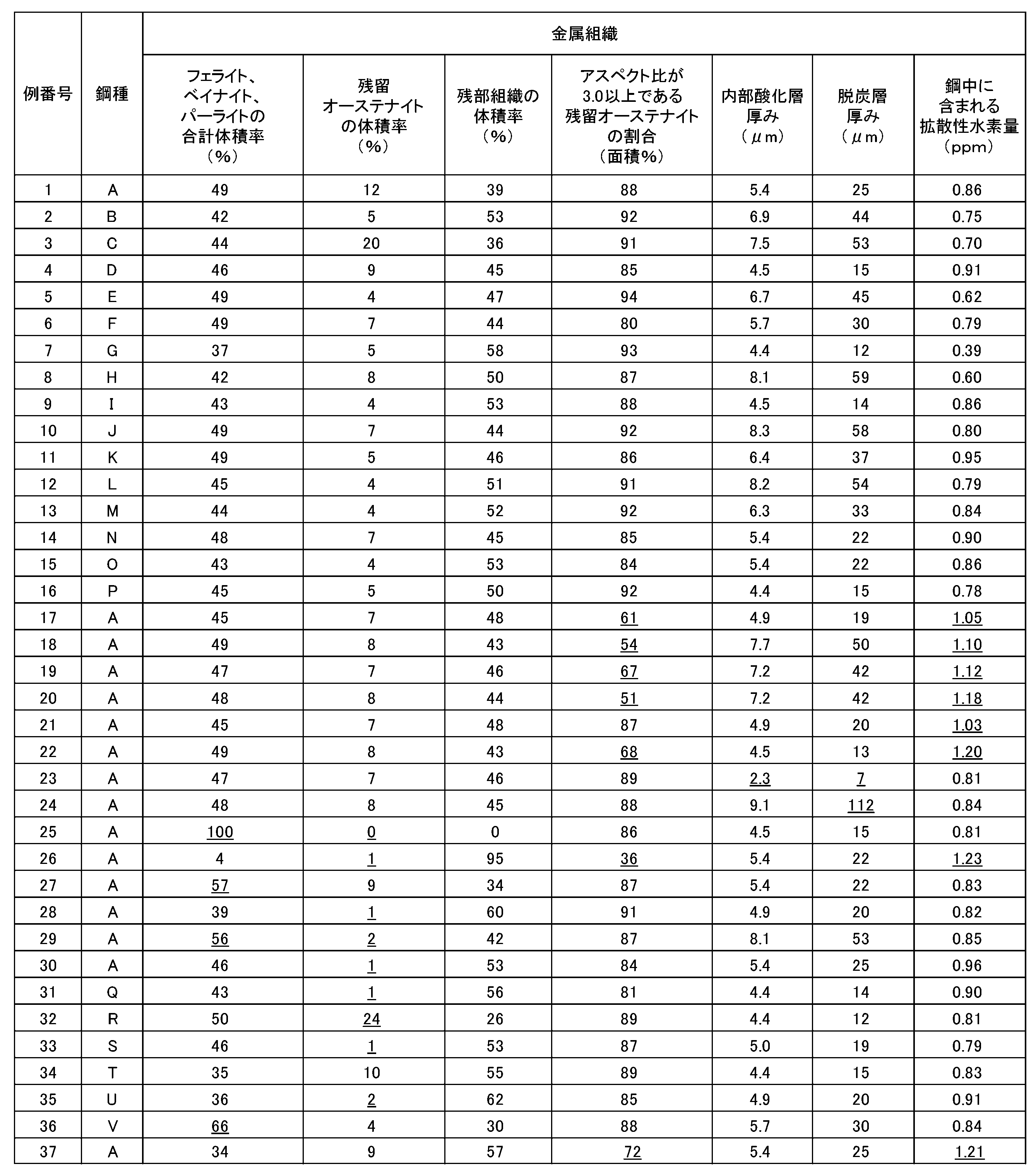
また、得られた鋼板の引張強さ(TS)、成形性の指標としての均一伸び(u-El)、打ち抜き加工を想定した耐衝突特性、スポット溶接部の耐LME特性を以下の方法で評価した。 <Measurement of characteristics>
In addition, the tensile strength (TS) of the obtained steel sheet, uniform elongation (u-El) as an index of formability, collision resistance assuming punching, and LME resistance of spot welds are evaluated by the following methods. did.
(均一伸び)
得られた鋼板から圧延方向に対し垂直方向にJIS Z 2241:2011に記載のJIS5号引張試験片を採取し、JIS Z 2241:2011に沿って引張試験を行うことで、引張強さ、均一伸びを測定した。
引張強さが980MPa以上の場合を合格とした。
また、均一伸び(%)が7.0%以上の場合に成形性に優れると判断した。
引張強さの測定結果を表6に示す。 (Tensile strength)
(Uniform elongation)
The JIS No. 5 tensile test piece described in JIS Z 2241: 2011 is collected from the obtained steel sheet in the direction perpendicular to the rolling direction, and a tensile test is performed along JIS Z 2241: 2011 to obtain tensile strength and uniform elongation. Was measured.
The case where the tensile strength was 980 MPa or more was regarded as acceptable.
Further, it was judged that the moldability was excellent when the uniform elongation (%) was 7.0% or more.
Table 6 shows the measurement results of the tensile strength.
耐衝突特性は、下記式に示すRの値の範囲によって評価した。
JIS5号引張試験片の両端中心部に直径10mmの半円状の打ち抜き穴をポンチ径10mm、打ち抜きクリアランスが12±2%の条件で作成しJISZ 2241:2011に沿って引っ張ったときの引張強さをTS1、JIS5号引張試験片の両端中心部に直径10mmの半円状のリーマ加工穴を機械加工にて入れJISZ 2241:2011に沿って引っ張ったときの引張強さをTS2とし、R=TS1/TS2とした。
R(=TS1/TS2)に応じて以下のように評価し、AまたはBであれば、耐衝突特性に優れると判断した。
A:R=0.96~1.00
B:R=0.93~0.96未満
C:R=0.93未満 (Collision resistance)
The collision resistance characteristics were evaluated by the range of R values shown in the following formula.
A semi-circular punched hole with a diameter of 10 mm was created at the center of both ends of the JIS No. 5 tensile test piece under the conditions of a punch diameter of 10 mm and a punching clearance of 12 ± 2%, and the tensile strength when pulled along JISZ 2241: 2011. TS1, a semi-circular reamer hole with a diameter of 10 mm was machined in the center of both ends of the JIS No. 5 tensile test piece, and the tensile strength when pulled along JISZ 2241: 2011 was set to TS2, and R = TS1. It was set to / TS2.
It was evaluated as follows according to R (= TS1 / TS2), and if it was A or B, it was judged that the collision resistance was excellent.
A: R = 0.96 to 1.00
B: R = 0.93 to less than 0.96 C: R = less than 0.93
得られた鋼板から、50mm×80mmの試験片を採取した。
また、表1におけるAの化学組成を有するスラブを鋳造し、例番号1の製造条件を適用した後、溶融亜鉛めっき浴に浸漬して、溶融亜鉛めっき鋼板(相手材)を製造した。製造した鋼板(相手材)から、50mm×80mmの試験片を採取した。
例番号1~37の鋼板のそれぞれから採取した試験片に、相手材である鋼板を重ね合わせて、図1に示すように2枚の鋼板をスポット溶接した。具体的には、相手材である溶融亜鉛めっき鋼板を図1の鋼板1dに用い、評価対象の鋼板(例番号1~37)を鋼板1eとして2枚を重ねて、一対の電極4a、4bでスポット溶接した。溶接条件として、サーボモータ加圧式単相交流スポット溶接機(電源周波数50Hz)を用いて、圧力450kgf(4413kg・m/s2)にて加圧しながら、電流値を6.5kA、電極の傾斜角θを3°として、アップスロープなし、通電時間0.4秒、通電終了後の保持時間を0.1秒とした。
スポット溶接後、鋼板の接合部のナゲット中心部の組織を、光学顕微鏡を用いて、倍率200倍から1000倍の間で観察した。観察の結果、割れが発生しない場合を“A”、100μm未満の長さの割れが認められる場合を“B”、100μm以上の長さの割れが認められる場合を“C”と評価し、A評価またはB評価の場合に、耐LME性に優れると判断した。 (LME resistance)
A 50 mm × 80 mm test piece was collected from the obtained steel sheet.
Further, a slab having the chemical composition of A in Table 1 was cast, and after applying the production conditions of Example No. 1, it was immersed in a hot-dip galvanized bath to produce a hot-dip galvanized steel sheet (mate material). A 50 mm × 80 mm test piece was collected from the manufactured steel sheet (mate material).
A steel plate as a mating material was superposed on the test pieces collected from each of the steel plates of Example Nos. 1 to 37, and two steel plates were spot welded as shown in FIG. Specifically, a hot-dip galvanized steel sheet, which is a mating material, is used as the
After spot welding, the structure of the center of the nugget at the joint of the steel sheets was observed using an optical microscope at a magnification of 200 to 1000 times. As a result of observation, when no cracks occur, it is evaluated as "A", when cracks with a length of less than 100 μm are observed, it is evaluated as "B", and when cracks with a length of 100 μm or more are observed, it is evaluated as “C”. In the case of evaluation or B evaluation, it was judged that the LME resistance was excellent.
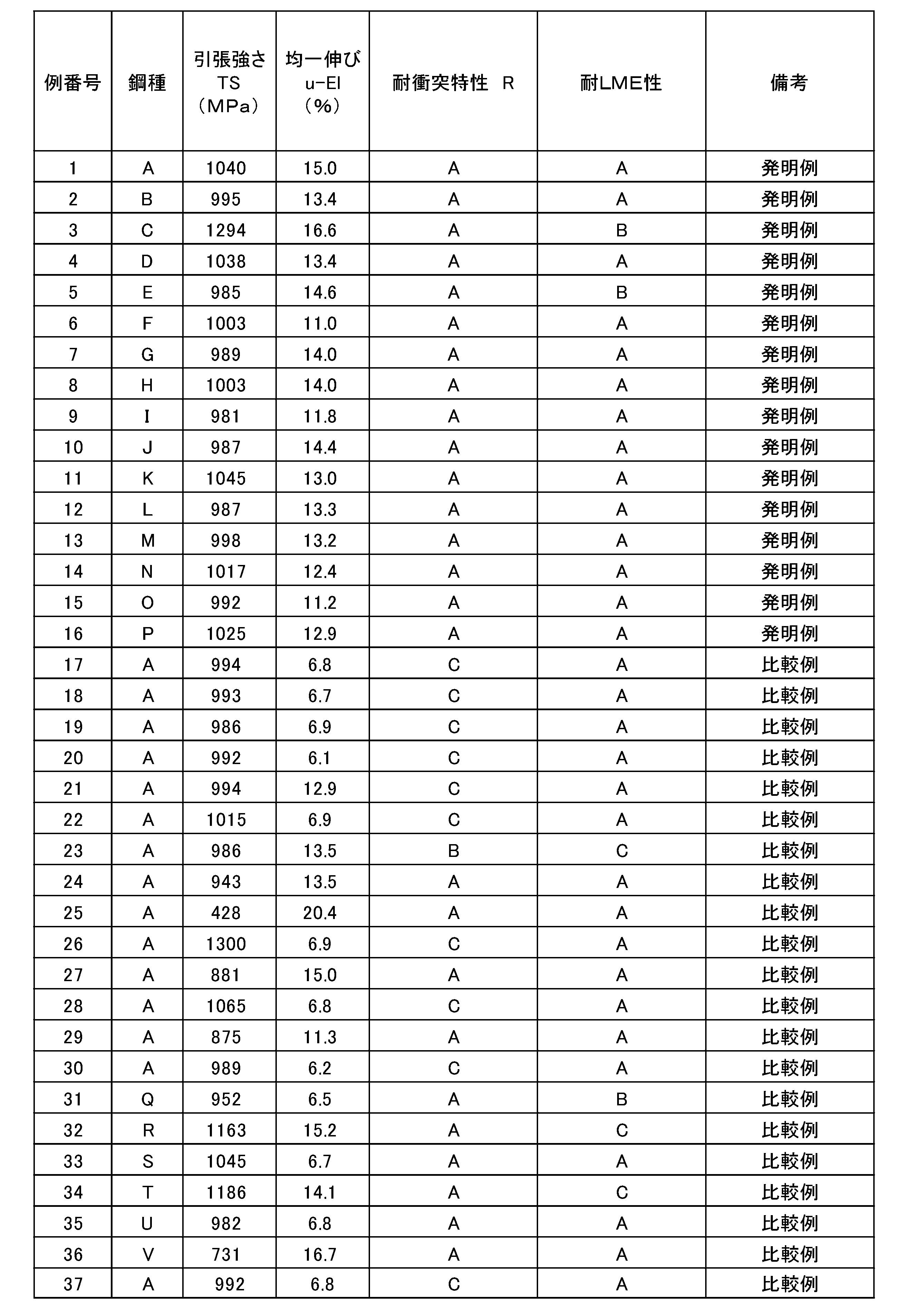
例番号18は、巻き取り温度が400℃より高かった。そのため、アスペクト比が3.0以上である残留オーステナイトの割合が小さく、鋼中に含まれる拡散性水素量が多かった。その結果、均一伸び、耐衝突特性が低かった。
例番号19は、冷間圧延工程で冷間圧延率が0.5%未満であったため、焼鈍後の組織でアスペクト比が3.0以上である残留オーステナイトの割合が小さく、鋼中に含まれる拡散性水素量が多かった。その結果、均一伸び、耐衝突特性が低かった。
例番号20は、冷間圧延工程で冷間圧延率が20.0%超であったため、焼鈍後の組織でアスペクト比が3.0以上である残留オーステナイトの割合が小さく、鋼中に含まれる拡散性水素量が多かった。その結果、均一伸び、耐衝突特性が低かった。
例番号21は、水素量低減工程において大気中で放置する時間が-2.4×T+96(時間:hour)未満であったため、拡散性水素量を十分に低減できなかった。その結果、耐衝突特性が低かった。
例番号22は、焼鈍工程の加熱過程において、曲げ曲げ戻しを付与しなかったために、焼鈍後の組織でアスペクト比が3.0以上である残留オーステナイトの割合が小さく、鋼中に含まれる拡散性水素量が多かった。その結果、均一伸び、耐衝突特性が低かった。
例番号23は、焼鈍工程の加熱過程において、露点が-20℃未満であったために、内部酸化層の厚みおよび脱炭層の厚みが十分に得られなかった。その結果、耐LME性が低かった。
例番号24は、焼鈍工程の加熱過程において、露点が20℃超であったために、脱炭層の厚みが過度になった。その結果、引張強さが低かった。
例番号25は、焼鈍工程の均熱過程において、保持温度がAc1点未満であったために、フェライト、ベイナイト、パーライトの合計面積率が50%を超え、残留オーステナイトの体積率が0%であった。その結果、引張強さが低かった。
例番号26は、焼鈍工程の均熱過程において、保持温度がAc3点超であったために、残留オーステナイトの体積率が小さくなり、またアスペクト比が3.0以上である残留オーステナイトの割合が小さくなった。その結果、耐衝突特性及び均一伸びが低かった。
例番号27は、焼鈍工程の冷却過程において、平均冷却速度が4℃/s未満であったために、フェライト、ベイナイト、パーライトの合計面積率が50%を超えた。その結果、引張強さが低かった。
例番号28は、焼鈍工程の保持過程において、保持温度が350℃未満であったために、残留オーステナイトが安定化せず、残留オーステナイトの体積率が小さくなった。その結果、均一伸びが低かった。
例番号29は、焼鈍工程の保持過程において、保持温度が480℃超であったために、フェライト、ベイナイト、パーライトの合計面積率が50%を超えた。その結果、引張強さが低かった。
例番号30は、焼鈍工程の保持過程において、保持時間が80秒未満であったために、残留オーステナイトが安定化せず、残留オーステナイトの体積率が小さくなった。その結果、均一伸びが低かった。 In Example No. 17, the minimum cooling rate from the hot rolling process end temperature to the take-up temperature was less than 5 ° C./s. Therefore, the proportion of retained austenite having an aspect ratio of 3.0 or more in the structure after annealing was small, and the amount of diffusible hydrogen contained in the steel was large. As a result, uniform elongation and collision resistance were low.
In Example No. 18, the take-up temperature was higher than 400 ° C. Therefore, the proportion of retained austenite having an aspect ratio of 3.0 or more was small, and the amount of diffusible hydrogen contained in the steel was large. As a result, uniform elongation and collision resistance were low.
In Example No. 19, since the cold rolling ratio was less than 0.5% in the cold rolling process, the proportion of retained austenite having an aspect ratio of 3.0 or more in the texture after annealing was small and contained in the steel. The amount of diffusible hydrogen was large. As a result, uniform elongation and collision resistance were low.
In Example No. 20, since the cold rolling ratio was more than 20.0% in the cold rolling process, the proportion of retained austenite having an aspect ratio of 3.0 or more in the texture after annealing was small and contained in the steel. The amount of diffusible hydrogen was large. As a result, uniform elongation and collision resistance were low.
In Example No. 21, the diffusible hydrogen amount could not be sufficiently reduced because the time left in the atmosphere in the hydrogen amount reduction step was less than -2.4 × T + 96 (time: hour). As a result, the collision resistance was low.
In Example No. 22, since bending and bending back were not applied in the heating process of the annealing step, the proportion of retained austenite having an aspect ratio of 3.0 or more in the structure after annealing was small, and the diffusivity contained in the steel was small. There was a lot of hydrogen. As a result, uniform elongation and collision resistance were low.
In Example No. 23, since the dew point was less than −20 ° C. in the heating process of the annealing step, the thickness of the internal oxide layer and the thickness of the decarburized layer could not be sufficiently obtained. As a result, the LME resistance was low.
In Example No. 24, the dew point was more than 20 ° C. in the heating process of the annealing step, so that the thickness of the decarburized layer became excessive. As a result, the tensile strength was low.
In Example No. 25, since the holding temperature was less than Ac1 point in the soaking process of the annealing step, the total area fraction of ferrite, bainite, and pearlite exceeded 50%, and the volume fraction of retained austenite was 0%. .. As a result, the tensile strength was low.
In Example No. 26, since the holding temperature was more than Ac3 points in the soaking process of the annealing step, the volume fraction of retained austenite became small, and the proportion of retained austenite having an aspect ratio of 3.0 or more became small. rice field. As a result, the collision resistance and uniform elongation were low.
In Example No. 27, since the average cooling rate was less than 4 ° C./s in the cooling process of the annealing step, the total area ratio of ferrite, bainite, and pearlite exceeded 50%. As a result, the tensile strength was low.
In Example No. 28, since the holding temperature was less than 350 ° C. in the holding process of the annealing step, the retained austenite was not stabilized and the volume fraction of the retained austenite became small. As a result, the uniform elongation was low.
In Example No. 29, since the holding temperature was over 480 ° C. in the holding process of the annealing step, the total area ratio of ferrite, bainite, and pearlite exceeded 50%. As a result, the tensile strength was low.
In Example No. 30, since the holding time was less than 80 seconds in the holding process of the annealing step, the retained austenite was not stabilized and the volume fraction of the retained austenite became small. As a result, the uniform elongation was low.
例番号32は、C含有量が0.40%超であったことで、耐LME性が低下した。
例番号33は、Si含有量が0.10%未満であったため、残留オーステナイトの体積率が不足した。その結果、均一伸びが低かった。
例番号34は、Si含有量が1.20%超であったことで、耐LME性が低下した。
例番号35は、Al含有量が0.30%未満であったため、残留オーステナイトの体積率が不足した。その結果、均一伸びが低かった。
例番号36は、Mn含有量が1.0%未満であったことで、フェライト、ベイナイト、パーライトの合計面積率が50%を超えた。その結果、引張強さが低かった。
例番号37は、冷間圧延工程での冷間圧延率が0.5%未満であり、また、水素量低減工程も行わなかったため、焼鈍後の組織でアスペクト比が3.0以上である残留オーステナイトの割合が小さく、鋼中に含まれる拡散性水素量が多かった。その結果、均一伸び、耐衝突特性が低かった。 In Example No. 31, the C content was less than 0.10%, so that the tensile strength was low. In addition, the volume fraction of retained austenite was insufficient. As a result, the uniform elongation was low.
In Example No. 32, the C content was more than 0.40%, so that the LME resistance was lowered.
In Example No. 33, the Si content was less than 0.10%, so that the volume fraction of retained austenite was insufficient. As a result, the uniform elongation was low.
In Example No. 34, the Si content was more than 1.20%, so that the LME resistance was lowered.
In Example No. 35, the volume fraction of retained austenite was insufficient because the Al content was less than 0.30%. As a result, the uniform elongation was low.
In Example No. 36, the Mn content was less than 1.0%, so that the total area ratio of ferrite, bainite, and pearlite exceeded 50%. As a result, the tensile strength was low.
In Example No. 37, the cold rolling ratio in the cold rolling step was less than 0.5%, and the hydrogen content reduction step was not performed, so that the residual structure after annealing had an aspect ratio of 3.0 or more. The proportion of austenite was small and the amount of diffusible hydrogen contained in the steel was large. As a result, uniform elongation and collision resistance were low.
4a、4b 電極 1d, 1e
Claims (6)
- 鋼板であって、
化学組成が、質量%で、
C:0.10~0.40%、
Si:0.10~1.20%、
Al:0.30~1.50%、
Mn:1.0~4.0%、
P:0.0200%以下、
S:0.0200%以下、
N:0.0200%以下、
O:0.0200%以下、
Ni:0~1.00%、
Mo:0~0.50%、
Cr:0~2.00%、
Ti:0~0.100%、
B:0~0.0100%、
Nb:0~0.10%、
V:0~0.50%、
Cu:0~0.50%、
W:0~0.10%、
Ta:0~0.100%、
Co:0~0.50%、
Mg:0~0.050%、
Ca:0~0.0500%、
Y:0~0.050%、
Zr:0~0.050%、
La:0~0.0500%、
Ce:0~0.050%、
Sn:0~0.05%、
Sb:0~0.050%、
As:0~0.050%、を含み、
残部がFeおよび不純物であり、
金属組織において、
フェライト、ベイナイト、パーライトの体積率が合計で0%以上、50%以下であり、
残留オーステナイトの体積率が3%以上、20%以下であり、
残部がフレッシュマルテンサイト及び焼き戻しマルテンサイトの1種または2種であり、
アスペクト比が3.0以上である残留オーステナイトが、面積率で、前記全残留オーステナイトのうちの80%以上を占め、
前記鋼板の表面からの厚みが4.0μm以上である内部酸化層と、前記鋼板の前記表面からの厚みが10μm以上100μm以下である脱炭層とを有し、
前記鋼板中に含まれる拡散性水素量が、質量基準で1.00ppm以下である、
鋼板。 It ’s a steel plate,
The chemical composition is by mass%,
C: 0.10 to 0.40%,
Si: 0.10 to 1.20%,
Al: 0.30 to 1.50%,
Mn: 1.0 to 4.0%,
P: 0.0200% or less,
S: 0.0200% or less,
N: 0.0200% or less,
O: 0.0200% or less,
Ni: 0 to 1.00%,
Mo: 0 to 0.50%,
Cr: 0 to 2.00%,
Ti: 0 to 0.100%,
B: 0 to 0.0100%,
Nb: 0 to 0.10%,
V: 0 to 0.50%,
Cu: 0 to 0.50%,
W: 0 to 0.10%,
Ta: 0 to 0.100%,
Co: 0 to 0.50%,
Mg: 0 to 0.050%,
Ca: 0-0.0500%,
Y: 0 to 0.050%,
Zr: 0 to 0.050%,
La: 0-0.0500%,
Ce: 0 to 0.050%,
Sn: 0 to 0.05%,
Sb: 0 to 0.050%,
As: 0 to 0.050%, including
The balance is Fe and impurities,
In the metallographic structure
The volume fractions of ferrite, bainite, and pearlite are 0% or more and 50% or less in total.
The volume fraction of retained austenite is 3% or more and 20% or less.
The rest is one or two types of fresh martensite and tempered martensite.
Retained austenite having an aspect ratio of 3.0 or more accounts for 80% or more of the total retained austenite in terms of area ratio.
It has an internal oxide layer having a thickness of 4.0 μm or more from the surface of the steel sheet and a decarburized layer having a thickness of 10 μm or more and 100 μm or less from the surface of the steel sheet.
The amount of diffusible hydrogen contained in the steel sheet is 1.00 ppm or less on a mass basis.
Steel plate. - 前記表面に溶融亜鉛めっき層を有する、請求項1に記載の鋼板。 The steel sheet according to claim 1, which has a hot-dip galvanized layer on the surface.
- 前記表面に合金化溶融亜鉛めっき層を有する、請求項1に記載の鋼板。 The steel sheet according to claim 1, which has an alloyed hot-dip galvanized layer on the surface.
- 請求項1に記載の前記化学組成を有するスラブを熱間圧延し、熱延鋼板とする熱間圧延工程と、
前記熱延鋼板を5℃/s以上の冷却速度で冷却し、400℃以下で巻き取る巻取工程と、
前記巻取工程後の前記熱延鋼板を、酸洗した後に、0.5%以上20.0%以下の圧下率で冷間圧延して冷延鋼板とする冷間圧延工程と、
前記冷延鋼板を、1時間以上かつ下記式(1)で表されるt時間以上の間、大気中で放置する水素量低減工程と、
前記水素量低減工程後の前記冷延鋼板を焼鈍する焼鈍工程と、
を有し、
前記焼鈍工程は、
前記冷延鋼板に対して、150~400℃において鋼板へ曲げ曲げ戻しを付与し、
前記冷延鋼板を、露点が-20℃から20℃の、0.1~30.0体積%の水素を含み残部が窒素および不純物である雰囲気で加熱し、
前記加熱後の前記冷延鋼板を、Ac1~Ac3℃の保持温度で1秒以上1000秒以下保持し、
前記保持後の前記冷延鋼板を、平均冷却速度4℃/s以上で100~340℃まで冷却し、
前記冷却後の前記冷延鋼板を、再加熱し、350℃以上480℃以下で80秒以上保持する、
鋼板の製造方法。
t=-2.4×T+96 (1)
ここで、T:放置時の平均気温(℃)である。 A hot-rolling step of hot-rolling a slab having the chemical composition according to claim 1 to obtain a hot-rolled steel sheet, and a hot-rolling step.
A winding process in which the hot-rolled steel sheet is cooled at a cooling rate of 5 ° C./s or higher and wound up at 400 ° C. or lower.
A cold rolling step of pickling the hot-rolled steel sheet after the winding step and then cold-rolling the hot-rolled steel sheet at a reduction ratio of 0.5% or more and 20.0% or less to obtain a cold-rolled steel sheet.
A hydrogen content reduction step of leaving the cold-rolled steel sheet in the atmosphere for 1 hour or more and t hours or more represented by the following formula (1).
An annealing step of annealing the cold-rolled steel sheet after the hydrogen amount reduction step, and
Have,
The annealing step is
The cold-rolled steel sheet is bent and bent back to the steel sheet at 150 to 400 ° C.
The cold-rolled steel sheet was heated in an atmosphere having a dew point of −20 ° C. to 20 ° C., containing 0.1 to 30.0% by volume of hydrogen, and the balance being nitrogen and impurities.
The cold-rolled steel sheet after heating is held at a holding temperature of Ac1 to Ac3 ° C. for 1 second or more and 1000 seconds or less.
The cold-rolled steel sheet after being held is cooled to 100 to 340 ° C. at an average cooling rate of 4 ° C./s or more.
The cooled rolled steel sheet is reheated and held at 350 ° C. or higher and 480 ° C. or lower for 80 seconds or longer.
Steel sheet manufacturing method.
t = -2.4 × T + 96 (1)
Here, T: is the average temperature (° C.) when left unattended. - さらに、前記焼鈍工程後の前記冷延鋼板を、(亜鉛めっき浴温度-40)℃~(亜鉛めっき浴温度+50)℃の温度域に制御した後、溶融亜鉛めっき浴に浸漬することにより、前記冷延鋼板の表面に溶融亜鉛めっきを形成する溶融亜鉛めっき工程を有する、
請求項4に記載の鋼板の製造方法。 Further, the cold-rolled steel sheet after the baking step is controlled to a temperature range of (zinc plating bath temperature −40) ° C. to (zinc plating bath temperature +50) ° C., and then immersed in a hot-dip zinc plating bath to obtain the above. It has a hot-dip zinc plating process that forms hot-dip zinc plating on the surface of a cold-rolled steel sheet.
The method for manufacturing a steel sheet according to claim 4. - さらに、前記溶融亜鉛めっき鋼板を、300~500℃の温度域に加熱してめっき層を合金化する合金化工程を有する、
請求項5に記載の鋼板の製造方法。 Further, the hot-dip galvanized steel sheet is heated to a temperature range of 300 to 500 ° C. to alloy the plated layer.
The method for manufacturing a steel sheet according to claim 5.
Priority Applications (6)
| Application Number | Priority Date | Filing Date | Title |
|---|---|---|---|
| JP2022574012A JPWO2022149502A1 (en) | 2021-01-07 | 2021-12-24 | |
| MX2023005834A MX2023005834A (en) | 2021-01-07 | 2021-12-24 | Steel sheet and method for producing same. |
| US18/035,066 US20240011114A1 (en) | 2021-01-07 | 2021-12-24 | Steel sheet and method for producing same |
| KR1020237016576A KR20230086778A (en) | 2021-01-07 | 2021-12-24 | Steel plate and its manufacturing method |
| CN202180078137.7A CN116507747A (en) | 2021-01-07 | 2021-12-24 | Steel sheet and method for producing same |
| EP21917722.7A EP4223894A4 (en) | 2021-01-07 | 2021-12-24 | Steel sheet and method for producing same |
Applications Claiming Priority (2)
| Application Number | Priority Date | Filing Date | Title |
|---|---|---|---|
| JP2021-001682 | 2021-01-07 | ||
| JP2021001682 | 2021-01-07 |
Publications (1)
| Publication Number | Publication Date |
|---|---|
| WO2022149502A1 true WO2022149502A1 (en) | 2022-07-14 |
Family
ID=82357915
Family Applications (1)
| Application Number | Title | Priority Date | Filing Date |
|---|---|---|---|
| PCT/JP2021/048346 WO2022149502A1 (en) | 2021-01-07 | 2021-12-24 | Steel sheet and method for producing same |
Country Status (7)
| Country | Link |
|---|---|
| US (1) | US20240011114A1 (en) |
| EP (1) | EP4223894A4 (en) |
| JP (1) | JPWO2022149502A1 (en) |
| KR (1) | KR20230086778A (en) |
| CN (1) | CN116507747A (en) |
| MX (1) | MX2023005834A (en) |
| WO (1) | WO2022149502A1 (en) |
Cited By (3)
| Publication number | Priority date | Publication date | Assignee | Title |
|---|---|---|---|---|
| CN117187682A (en) * | 2023-04-28 | 2023-12-08 | 鞍钢股份有限公司 | 1200MPa battery pack steel for new energy automobile and preparation method thereof |
| JP7468815B1 (en) | 2022-10-27 | 2024-04-16 | Jfeスチール株式会社 | High-strength plated steel sheet and method for producing same |
| JP7468816B1 (en) | 2022-10-27 | 2024-04-16 | Jfeスチール株式会社 | High-strength plated steel sheet and method for producing same |
Citations (8)
| Publication number | Priority date | Publication date | Assignee | Title |
|---|---|---|---|---|
| JP2016130357A (en) * | 2015-01-09 | 2016-07-21 | 株式会社神戸製鋼所 | High-strength plated steel sheet, as well as method for producing the same |
| WO2018043453A1 (en) | 2016-08-30 | 2018-03-08 | Jfeスチール株式会社 | Thin steel sheet and process for producing same |
| WO2019116531A1 (en) * | 2017-12-15 | 2019-06-20 | 日本製鉄株式会社 | Steel sheet, hot-dip zinc-coated steel sheet, and alloyed hot-dip zinc-coated steel sheet |
| WO2019187060A1 (en) | 2018-03-30 | 2019-10-03 | 日本製鉄株式会社 | Steel sheet and manufacturing method therefor |
| WO2020130631A1 (en) * | 2018-12-19 | 2020-06-25 | 주식회사 포스코 | High-strength galvanized steel sheet having excellent electrical resistance spot weldability, and method for producing same |
| JP2021001682A (en) | 2019-06-19 | 2021-01-07 | 株式会社ジェイテクト | Sealing member |
| WO2021200579A1 (en) * | 2020-03-31 | 2021-10-07 | Jfeスチール株式会社 | Steel sheet, member, and method for manufacturing same |
| WO2021200580A1 (en) * | 2020-03-31 | 2021-10-07 | Jfeスチール株式会社 | Steel sheet, member, and methods for producing same |
Family Cites Families (1)
| Publication number | Priority date | Publication date | Assignee | Title |
|---|---|---|---|---|
| CN111902552B (en) * | 2018-03-30 | 2022-06-14 | 日本制铁株式会社 | Alloyed hot-dip galvanized steel sheet |
-
2021
- 2021-12-24 EP EP21917722.7A patent/EP4223894A4/en active Pending
- 2021-12-24 JP JP2022574012A patent/JPWO2022149502A1/ja active Pending
- 2021-12-24 US US18/035,066 patent/US20240011114A1/en active Pending
- 2021-12-24 KR KR1020237016576A patent/KR20230086778A/en unknown
- 2021-12-24 WO PCT/JP2021/048346 patent/WO2022149502A1/en active Application Filing
- 2021-12-24 CN CN202180078137.7A patent/CN116507747A/en active Pending
- 2021-12-24 MX MX2023005834A patent/MX2023005834A/en unknown
Patent Citations (8)
| Publication number | Priority date | Publication date | Assignee | Title |
|---|---|---|---|---|
| JP2016130357A (en) * | 2015-01-09 | 2016-07-21 | 株式会社神戸製鋼所 | High-strength plated steel sheet, as well as method for producing the same |
| WO2018043453A1 (en) | 2016-08-30 | 2018-03-08 | Jfeスチール株式会社 | Thin steel sheet and process for producing same |
| WO2019116531A1 (en) * | 2017-12-15 | 2019-06-20 | 日本製鉄株式会社 | Steel sheet, hot-dip zinc-coated steel sheet, and alloyed hot-dip zinc-coated steel sheet |
| WO2019187060A1 (en) | 2018-03-30 | 2019-10-03 | 日本製鉄株式会社 | Steel sheet and manufacturing method therefor |
| WO2020130631A1 (en) * | 2018-12-19 | 2020-06-25 | 주식회사 포스코 | High-strength galvanized steel sheet having excellent electrical resistance spot weldability, and method for producing same |
| JP2021001682A (en) | 2019-06-19 | 2021-01-07 | 株式会社ジェイテクト | Sealing member |
| WO2021200579A1 (en) * | 2020-03-31 | 2021-10-07 | Jfeスチール株式会社 | Steel sheet, member, and method for manufacturing same |
| WO2021200580A1 (en) * | 2020-03-31 | 2021-10-07 | Jfeスチール株式会社 | Steel sheet, member, and methods for producing same |
Non-Patent Citations (1)
| Title |
|---|
| See also references of EP4223894A4 |
Cited By (3)
| Publication number | Priority date | Publication date | Assignee | Title |
|---|---|---|---|---|
| JP7468815B1 (en) | 2022-10-27 | 2024-04-16 | Jfeスチール株式会社 | High-strength plated steel sheet and method for producing same |
| JP7468816B1 (en) | 2022-10-27 | 2024-04-16 | Jfeスチール株式会社 | High-strength plated steel sheet and method for producing same |
| CN117187682A (en) * | 2023-04-28 | 2023-12-08 | 鞍钢股份有限公司 | 1200MPa battery pack steel for new energy automobile and preparation method thereof |
Also Published As
| Publication number | Publication date |
|---|---|
| EP4223894A1 (en) | 2023-08-09 |
| EP4223894A4 (en) | 2024-03-13 |
| JPWO2022149502A1 (en) | 2022-07-14 |
| KR20230086778A (en) | 2023-06-15 |
| CN116507747A (en) | 2023-07-28 |
| MX2023005834A (en) | 2023-06-02 |
| US20240011114A1 (en) | 2024-01-11 |
Similar Documents
| Publication | Publication Date | Title |
|---|---|---|
| EP3309273B1 (en) | Galvannealed steel sheet and method for manufacturing same | |
| JP5354135B2 (en) | High-strength hot-dip galvanized steel sheet excellent in mechanical cutting characteristics, high-strength galvannealed steel sheet, and methods for producing them | |
| US8840834B2 (en) | High-strength steel sheet and method for manufacturing the same | |
| EP3216886A1 (en) | Hot-dip galvanized steel sheet | |
| WO2022149502A1 (en) | Steel sheet and method for producing same | |
| EP2757169A1 (en) | High-strength steel sheet having excellent workability and method for producing same | |
| CN114981457B (en) | High-strength galvanized steel sheet and method for producing same | |
| JP6760524B1 (en) | High-strength hot-dip galvanized steel sheet and its manufacturing method | |
| CN114585766B (en) | High-strength steel sheet and method for producing same | |
| CN114555845B (en) | High-strength steel sheet and method for producing same | |
| CN114585765B (en) | High-strength steel sheet and method for producing same | |
| WO2021200579A1 (en) | Steel sheet, member, and method for manufacturing same | |
| CN115698361B (en) | Steel sheet, member, and method for producing same | |
| JP6947334B1 (en) | High-strength steel plate and its manufacturing method | |
| CN114585758B (en) | High-strength steel sheet, impact absorbing member, and method for producing high-strength steel sheet | |
| JP7311808B2 (en) | Steel plate and its manufacturing method | |
| EP4137593A1 (en) | Steel sheet, member, method for producing said steel sheet, and method for producing said member | |
| WO2022196733A1 (en) | Steel sheet, steel member, and coated steel member | |
| CN116806274A (en) | High-strength steel sheet and method for producing same | |
| CN114585759A (en) | High-strength steel sheet, impact absorbing member, and method for producing high-strength steel sheet |
Legal Events
| Date | Code | Title | Description |
|---|---|---|---|
| 121 | Ep: the epo has been informed by wipo that ep was designated in this application |
Ref document number: 21917722 Country of ref document: EP Kind code of ref document: A1 |
|
| ENP | Entry into the national phase |
Ref document number: 2022574012 Country of ref document: JP Kind code of ref document: A |
|
| WWE | Wipo information: entry into national phase |
Ref document number: 18035066 Country of ref document: US |
|
| ENP | Entry into the national phase |
Ref document number: 2021917722 Country of ref document: EP Effective date: 20230503 |
|
| ENP | Entry into the national phase |
Ref document number: 20237016576 Country of ref document: KR Kind code of ref document: A |
|
| WWE | Wipo information: entry into national phase |
Ref document number: 202180078137.7 Country of ref document: CN |
|
| NENP | Non-entry into the national phase |
Ref country code: DE |