EP4137593A1 - Steel sheet, member, method for producing said steel sheet, and method for producing said member - Google Patents
Steel sheet, member, method for producing said steel sheet, and method for producing said member Download PDFInfo
- Publication number
- EP4137593A1 EP4137593A1 EP21832103.2A EP21832103A EP4137593A1 EP 4137593 A1 EP4137593 A1 EP 4137593A1 EP 21832103 A EP21832103 A EP 21832103A EP 4137593 A1 EP4137593 A1 EP 4137593A1
- Authority
- EP
- European Patent Office
- Prior art keywords
- steel sheet
- less
- rolling
- temperature
- hot
- Prior art date
- Legal status (The legal status is an assumption and is not a legal conclusion. Google has not performed a legal analysis and makes no representation as to the accuracy of the status listed.)
- Pending
Links
Images


Classifications
-
- C—CHEMISTRY; METALLURGY
- C22—METALLURGY; FERROUS OR NON-FERROUS ALLOYS; TREATMENT OF ALLOYS OR NON-FERROUS METALS
- C22C—ALLOYS
- C22C38/00—Ferrous alloys, e.g. steel alloys
- C22C38/04—Ferrous alloys, e.g. steel alloys containing manganese
-
- C—CHEMISTRY; METALLURGY
- C21—METALLURGY OF IRON
- C21D—MODIFYING THE PHYSICAL STRUCTURE OF FERROUS METALS; GENERAL DEVICES FOR HEAT TREATMENT OF FERROUS OR NON-FERROUS METALS OR ALLOYS; MAKING METAL MALLEABLE, e.g. BY DECARBURISATION OR TEMPERING
- C21D1/00—General methods or devices for heat treatment, e.g. annealing, hardening, quenching or tempering
- C21D1/18—Hardening; Quenching with or without subsequent tempering
- C21D1/185—Hardening; Quenching with or without subsequent tempering from an intercritical temperature
-
- C—CHEMISTRY; METALLURGY
- C21—METALLURGY OF IRON
- C21D—MODIFYING THE PHYSICAL STRUCTURE OF FERROUS METALS; GENERAL DEVICES FOR HEAT TREATMENT OF FERROUS OR NON-FERROUS METALS OR ALLOYS; MAKING METAL MALLEABLE, e.g. BY DECARBURISATION OR TEMPERING
- C21D1/00—General methods or devices for heat treatment, e.g. annealing, hardening, quenching or tempering
- C21D1/18—Hardening; Quenching with or without subsequent tempering
- C21D1/25—Hardening, combined with annealing between 300 degrees Celsius and 600 degrees Celsius, i.e. heat refining ("Vergüten")
-
- C—CHEMISTRY; METALLURGY
- C21—METALLURGY OF IRON
- C21D—MODIFYING THE PHYSICAL STRUCTURE OF FERROUS METALS; GENERAL DEVICES FOR HEAT TREATMENT OF FERROUS OR NON-FERROUS METALS OR ALLOYS; MAKING METAL MALLEABLE, e.g. BY DECARBURISATION OR TEMPERING
- C21D8/00—Modifying the physical properties by deformation combined with, or followed by, heat treatment
- C21D8/02—Modifying the physical properties by deformation combined with, or followed by, heat treatment during manufacturing of plates or strips
- C21D8/0221—Modifying the physical properties by deformation combined with, or followed by, heat treatment during manufacturing of plates or strips characterised by the working steps
- C21D8/0226—Hot rolling
-
- C—CHEMISTRY; METALLURGY
- C21—METALLURGY OF IRON
- C21D—MODIFYING THE PHYSICAL STRUCTURE OF FERROUS METALS; GENERAL DEVICES FOR HEAT TREATMENT OF FERROUS OR NON-FERROUS METALS OR ALLOYS; MAKING METAL MALLEABLE, e.g. BY DECARBURISATION OR TEMPERING
- C21D8/00—Modifying the physical properties by deformation combined with, or followed by, heat treatment
- C21D8/02—Modifying the physical properties by deformation combined with, or followed by, heat treatment during manufacturing of plates or strips
- C21D8/0221—Modifying the physical properties by deformation combined with, or followed by, heat treatment during manufacturing of plates or strips characterised by the working steps
- C21D8/0236—Cold rolling
-
- C—CHEMISTRY; METALLURGY
- C21—METALLURGY OF IRON
- C21D—MODIFYING THE PHYSICAL STRUCTURE OF FERROUS METALS; GENERAL DEVICES FOR HEAT TREATMENT OF FERROUS OR NON-FERROUS METALS OR ALLOYS; MAKING METAL MALLEABLE, e.g. BY DECARBURISATION OR TEMPERING
- C21D8/00—Modifying the physical properties by deformation combined with, or followed by, heat treatment
- C21D8/02—Modifying the physical properties by deformation combined with, or followed by, heat treatment during manufacturing of plates or strips
- C21D8/0247—Modifying the physical properties by deformation combined with, or followed by, heat treatment during manufacturing of plates or strips characterised by the heat treatment
- C21D8/0273—Final recrystallisation annealing
-
- C—CHEMISTRY; METALLURGY
- C21—METALLURGY OF IRON
- C21D—MODIFYING THE PHYSICAL STRUCTURE OF FERROUS METALS; GENERAL DEVICES FOR HEAT TREATMENT OF FERROUS OR NON-FERROUS METALS OR ALLOYS; MAKING METAL MALLEABLE, e.g. BY DECARBURISATION OR TEMPERING
- C21D9/00—Heat treatment, e.g. annealing, hardening, quenching or tempering, adapted for particular articles; Furnaces therefor
- C21D9/46—Heat treatment, e.g. annealing, hardening, quenching or tempering, adapted for particular articles; Furnaces therefor for sheet metals
-
- C—CHEMISTRY; METALLURGY
- C22—METALLURGY; FERROUS OR NON-FERROUS ALLOYS; TREATMENT OF ALLOYS OR NON-FERROUS METALS
- C22C—ALLOYS
- C22C38/00—Ferrous alloys, e.g. steel alloys
- C22C38/001—Ferrous alloys, e.g. steel alloys containing N
-
- C—CHEMISTRY; METALLURGY
- C22—METALLURGY; FERROUS OR NON-FERROUS ALLOYS; TREATMENT OF ALLOYS OR NON-FERROUS METALS
- C22C—ALLOYS
- C22C38/00—Ferrous alloys, e.g. steel alloys
- C22C38/002—Ferrous alloys, e.g. steel alloys containing In, Mg, or other elements not provided for in one single group C22C38/001 - C22C38/60
-
- C—CHEMISTRY; METALLURGY
- C22—METALLURGY; FERROUS OR NON-FERROUS ALLOYS; TREATMENT OF ALLOYS OR NON-FERROUS METALS
- C22C—ALLOYS
- C22C38/00—Ferrous alloys, e.g. steel alloys
- C22C38/005—Ferrous alloys, e.g. steel alloys containing rare earths, i.e. Sc, Y, Lanthanides
-
- C—CHEMISTRY; METALLURGY
- C22—METALLURGY; FERROUS OR NON-FERROUS ALLOYS; TREATMENT OF ALLOYS OR NON-FERROUS METALS
- C22C—ALLOYS
- C22C38/00—Ferrous alloys, e.g. steel alloys
- C22C38/008—Ferrous alloys, e.g. steel alloys containing tin
-
- C—CHEMISTRY; METALLURGY
- C22—METALLURGY; FERROUS OR NON-FERROUS ALLOYS; TREATMENT OF ALLOYS OR NON-FERROUS METALS
- C22C—ALLOYS
- C22C38/00—Ferrous alloys, e.g. steel alloys
- C22C38/02—Ferrous alloys, e.g. steel alloys containing silicon
-
- C—CHEMISTRY; METALLURGY
- C22—METALLURGY; FERROUS OR NON-FERROUS ALLOYS; TREATMENT OF ALLOYS OR NON-FERROUS METALS
- C22C—ALLOYS
- C22C38/00—Ferrous alloys, e.g. steel alloys
- C22C38/06—Ferrous alloys, e.g. steel alloys containing aluminium
-
- C—CHEMISTRY; METALLURGY
- C22—METALLURGY; FERROUS OR NON-FERROUS ALLOYS; TREATMENT OF ALLOYS OR NON-FERROUS METALS
- C22C—ALLOYS
- C22C38/00—Ferrous alloys, e.g. steel alloys
- C22C38/08—Ferrous alloys, e.g. steel alloys containing nickel
-
- C—CHEMISTRY; METALLURGY
- C22—METALLURGY; FERROUS OR NON-FERROUS ALLOYS; TREATMENT OF ALLOYS OR NON-FERROUS METALS
- C22C—ALLOYS
- C22C38/00—Ferrous alloys, e.g. steel alloys
- C22C38/12—Ferrous alloys, e.g. steel alloys containing tungsten, tantalum, molybdenum, vanadium, or niobium
-
- C—CHEMISTRY; METALLURGY
- C22—METALLURGY; FERROUS OR NON-FERROUS ALLOYS; TREATMENT OF ALLOYS OR NON-FERROUS METALS
- C22C—ALLOYS
- C22C38/00—Ferrous alloys, e.g. steel alloys
- C22C38/14—Ferrous alloys, e.g. steel alloys containing titanium or zirconium
-
- C—CHEMISTRY; METALLURGY
- C22—METALLURGY; FERROUS OR NON-FERROUS ALLOYS; TREATMENT OF ALLOYS OR NON-FERROUS METALS
- C22C—ALLOYS
- C22C38/00—Ferrous alloys, e.g. steel alloys
- C22C38/16—Ferrous alloys, e.g. steel alloys containing copper
-
- C—CHEMISTRY; METALLURGY
- C22—METALLURGY; FERROUS OR NON-FERROUS ALLOYS; TREATMENT OF ALLOYS OR NON-FERROUS METALS
- C22C—ALLOYS
- C22C38/00—Ferrous alloys, e.g. steel alloys
- C22C38/18—Ferrous alloys, e.g. steel alloys containing chromium
- C22C38/28—Ferrous alloys, e.g. steel alloys containing chromium with titanium or zirconium
-
- C—CHEMISTRY; METALLURGY
- C22—METALLURGY; FERROUS OR NON-FERROUS ALLOYS; TREATMENT OF ALLOYS OR NON-FERROUS METALS
- C22C—ALLOYS
- C22C38/00—Ferrous alloys, e.g. steel alloys
- C22C38/18—Ferrous alloys, e.g. steel alloys containing chromium
- C22C38/32—Ferrous alloys, e.g. steel alloys containing chromium with boron
-
- C—CHEMISTRY; METALLURGY
- C22—METALLURGY; FERROUS OR NON-FERROUS ALLOYS; TREATMENT OF ALLOYS OR NON-FERROUS METALS
- C22C—ALLOYS
- C22C38/00—Ferrous alloys, e.g. steel alloys
- C22C38/18—Ferrous alloys, e.g. steel alloys containing chromium
- C22C38/34—Ferrous alloys, e.g. steel alloys containing chromium with more than 1.5% by weight of silicon
-
- C—CHEMISTRY; METALLURGY
- C22—METALLURGY; FERROUS OR NON-FERROUS ALLOYS; TREATMENT OF ALLOYS OR NON-FERROUS METALS
- C22C—ALLOYS
- C22C38/00—Ferrous alloys, e.g. steel alloys
- C22C38/18—Ferrous alloys, e.g. steel alloys containing chromium
- C22C38/38—Ferrous alloys, e.g. steel alloys containing chromium with more than 1.5% by weight of manganese
-
- C—CHEMISTRY; METALLURGY
- C22—METALLURGY; FERROUS OR NON-FERROUS ALLOYS; TREATMENT OF ALLOYS OR NON-FERROUS METALS
- C22C—ALLOYS
- C22C38/00—Ferrous alloys, e.g. steel alloys
- C22C38/18—Ferrous alloys, e.g. steel alloys containing chromium
- C22C38/40—Ferrous alloys, e.g. steel alloys containing chromium with nickel
- C22C38/58—Ferrous alloys, e.g. steel alloys containing chromium with nickel with more than 1.5% by weight of manganese
-
- C—CHEMISTRY; METALLURGY
- C22—METALLURGY; FERROUS OR NON-FERROUS ALLOYS; TREATMENT OF ALLOYS OR NON-FERROUS METALS
- C22C—ALLOYS
- C22C38/00—Ferrous alloys, e.g. steel alloys
- C22C38/60—Ferrous alloys, e.g. steel alloys containing lead, selenium, tellurium, or antimony, or more than 0.04% by weight of sulfur
-
- C—CHEMISTRY; METALLURGY
- C23—COATING METALLIC MATERIAL; COATING MATERIAL WITH METALLIC MATERIAL; CHEMICAL SURFACE TREATMENT; DIFFUSION TREATMENT OF METALLIC MATERIAL; COATING BY VACUUM EVAPORATION, BY SPUTTERING, BY ION IMPLANTATION OR BY CHEMICAL VAPOUR DEPOSITION, IN GENERAL; INHIBITING CORROSION OF METALLIC MATERIAL OR INCRUSTATION IN GENERAL
- C23C—COATING METALLIC MATERIAL; COATING MATERIAL WITH METALLIC MATERIAL; SURFACE TREATMENT OF METALLIC MATERIAL BY DIFFUSION INTO THE SURFACE, BY CHEMICAL CONVERSION OR SUBSTITUTION; COATING BY VACUUM EVAPORATION, BY SPUTTERING, BY ION IMPLANTATION OR BY CHEMICAL VAPOUR DEPOSITION, IN GENERAL
- C23C2/00—Hot-dipping or immersion processes for applying the coating material in the molten state without affecting the shape; Apparatus therefor
- C23C2/04—Hot-dipping or immersion processes for applying the coating material in the molten state without affecting the shape; Apparatus therefor characterised by the coating material
- C23C2/06—Zinc or cadmium or alloys based thereon
-
- C—CHEMISTRY; METALLURGY
- C21—METALLURGY OF IRON
- C21D—MODIFYING THE PHYSICAL STRUCTURE OF FERROUS METALS; GENERAL DEVICES FOR HEAT TREATMENT OF FERROUS OR NON-FERROUS METALS OR ALLOYS; MAKING METAL MALLEABLE, e.g. BY DECARBURISATION OR TEMPERING
- C21D2211/00—Microstructure comprising significant phases
- C21D2211/001—Austenite
-
- C—CHEMISTRY; METALLURGY
- C21—METALLURGY OF IRON
- C21D—MODIFYING THE PHYSICAL STRUCTURE OF FERROUS METALS; GENERAL DEVICES FOR HEAT TREATMENT OF FERROUS OR NON-FERROUS METALS OR ALLOYS; MAKING METAL MALLEABLE, e.g. BY DECARBURISATION OR TEMPERING
- C21D2211/00—Microstructure comprising significant phases
- C21D2211/002—Bainite
-
- C—CHEMISTRY; METALLURGY
- C21—METALLURGY OF IRON
- C21D—MODIFYING THE PHYSICAL STRUCTURE OF FERROUS METALS; GENERAL DEVICES FOR HEAT TREATMENT OF FERROUS OR NON-FERROUS METALS OR ALLOYS; MAKING METAL MALLEABLE, e.g. BY DECARBURISATION OR TEMPERING
- C21D2211/00—Microstructure comprising significant phases
- C21D2211/005—Ferrite
-
- C—CHEMISTRY; METALLURGY
- C21—METALLURGY OF IRON
- C21D—MODIFYING THE PHYSICAL STRUCTURE OF FERROUS METALS; GENERAL DEVICES FOR HEAT TREATMENT OF FERROUS OR NON-FERROUS METALS OR ALLOYS; MAKING METAL MALLEABLE, e.g. BY DECARBURISATION OR TEMPERING
- C21D2211/00—Microstructure comprising significant phases
- C21D2211/008—Martensite
-
- Y—GENERAL TAGGING OF NEW TECHNOLOGICAL DEVELOPMENTS; GENERAL TAGGING OF CROSS-SECTIONAL TECHNOLOGIES SPANNING OVER SEVERAL SECTIONS OF THE IPC; TECHNICAL SUBJECTS COVERED BY FORMER USPC CROSS-REFERENCE ART COLLECTIONS [XRACs] AND DIGESTS
- Y02—TECHNOLOGIES OR APPLICATIONS FOR MITIGATION OR ADAPTATION AGAINST CLIMATE CHANGE
- Y02P—CLIMATE CHANGE MITIGATION TECHNOLOGIES IN THE PRODUCTION OR PROCESSING OF GOODS
- Y02P10/00—Technologies related to metal processing
- Y02P10/20—Recycling
Definitions
- the present invention relates to a high-strength steel sheet or member with good collision characteristics and a method for producing the steel sheet or member.
- a steel sheet according to the present invention can be suitably used for parts mainly used in the automotive field.
- non-deformable members such as pillars and bumpers
- energy-absorbing members such as side members.
- TS tensile strength
- energy-absorbing members have not been significantly increased strength, and the strength level of practical steel is a TS of approximately 590 MPa or less.
- One reason for little increase of strength is member fracture in collision deformation.
- high-tensile-strength steel tends to cause a member fracture originating from a portion subjected to primary processing of forming and cannot consistently absorb collision energy.
- member fracture there is room for preventing member fracture in case of a collision, consistently exhibiting high energy absorption to ensure safety in case of a collision, and reducing weight to contribute to environmental conservation.
- a high-strength steel sheet with good collision characteristics and with a TS of 590 MPa or more should be applied to an energy-absorbing member.
- Patent Literature 1 discloses a technique related to an ultra-high-strength steel sheet with high formability and impact resistance and with a TS of 1200 MPa.
- Patent Literature 2 discloses a technique related to a high-strength steel sheet with a maximum tensile strength of 780 MPa or more applicable to an impact-absorbing member in case of a collision.
- Patent Literature 1 Although collision characteristics are examined in Patent Literature 1, impact resistance is examined on the assumption that a member is not broken in case of a collision, and collision characteristics are not examined from the perspective of member fracture resistance.
- Patent Literature 2 a dynamic axial crushing test with a falling weight is performed on a hat-shaped member to evaluate cracking and fracture resistance at a TS of more than 780 MPa.
- rating cracking after crushing cannot evaluate the process from the initiation of a crack during the crushing to the fracture, which is important for collision characteristics. This is because, if a crack occurs early in the process of crushing, even a small crack that does not passes through the sheet may reduce absorbing energy. Furthermore, if a crack occurs in the later stage in the process of crushing, even a large crack that passes through the sheet may have little effect on absorbing energy. Thus, only rating cracking after crushing is probably insufficient for the evaluation of fracture resistance.
- TS tensile strength
- a steel sheet has a chemical composition satisfying an equivalent carbon content Ceq of 0.35% or more and less than 0.60% and a steel microstructure with an area fraction of ferrite: 40% to 85%, tempered martensite and bainite: 10% to 55% in total, retained austenite: 3% to 15%, and ferrite, tempered martensite, bainite, and retained austenite: 93% or more in total, wherein specified 90-degree bending of the steel sheet causes a change of 0.50 or more in (a grain size in a thickness direction)/(a grain size in a direction perpendicular to the thickness) of the tempered martensite in an L cross section in a 0- to 50- ⁇ m region from a surface of the steel sheet on a compression side. It has been found that these can provide a high-strength steel sheet with good collision characteristics.
- the present invention can provide a steel sheet with a tensile strength (TS) of 590 MPa or more and with good collision characteristics.
- TS tensile strength
- a member produced by performing forming, welding, or the like on a steel sheet according to the present invention can be suitably used as an energy-absorbing member used in the automotive field.
- a steel sheet according to the present invention has
- the equivalent carbon content Ceq refers to the effects of elements other than C converted into the C content as a measure of the strength of steel. Setting the equivalent carbon content Ceq to 0.35% or more and less than 0.60% allows the area fraction of each metallic microstructure, such as ferrite, described later to be controlled within the scope of the present invention. Setting the equivalent carbon content Ceq to 0.35% or more, preferably 0.40% or more, can provide the strength of the present invention. On the other hand, setting the equivalent carbon content Ceq to less than 0.60%, preferably 0.55% or less, can produce the effect of improving collision characteristics in the present invention.
- the [element symbol %] in the formula represents the element content (% by mass) and is 0 for an element not contained.
- an area fraction of ferrite of less than 40% may result in an excessive volume fraction of tempered martensite and poor collision characteristics.
- the area fraction of ferrite is 40% or more, preferably 50% or more.
- an area fraction of ferrite of more than 85% may result in an excessive volume fraction of ferrite and a lower TS.
- the area fraction of ferrite is 85% or less, preferably 80% or less, more preferably 75% or less, still more preferably 70% or less.
- Tempered martensite and bainite are effective in reducing member fracture in collision deformation, improving absorbing energy, and increasing strength.
- a total area fraction of tempered martensite and bainite of less than 10% may result in a lower TS.
- the total area fraction is 10% or more, preferably 20% or more.
- a total area fraction of tempered martensite and bainite of more than 55% may result in poor collision characteristics.
- the total area fraction is 55% or less, preferably 50% or less.
- each of tempered martensite and bainite may have any area fraction in the above range, the area fraction of bainite preferably ranges from 3% to 20%.
- the reason for this preferred range may be as follows: bainite is effective in concentrating C in untransformed austenite during the holding in the tempering step and forming retained austenite and in improving absorbed energy in case of a collision. Such effects may be small at an area fraction of bainite of less than 3%.
- an area fraction of bainite of more than 20% results in excessive concentration of C in untransformed austenite during the holding in the tempering step and a decrease in martensite transformation start temperature Ms (hereinafter also referred to simply as an Ms temperature or Ms).
- the area fraction of bainite is preferably 3% or more.
- the area fraction of bainite is preferably 20% or less.
- the area fraction of bainite is more preferably 5% or more, still more preferably 8% or more.
- the area fraction of bainite is more preferably 18% or less, still more preferably 15% or less.
- Retained austenite is effective in retarding cracking in case of a collision and improving collision characteristics.
- the mechanism is not clear but may be as follows: retained austenite is work-hardened in collision deformation, increases the curvature radius in bending deformation, and disperses strain in a bent portion. The dispersion of strain reduces stress concentration in a void forming portion in the primary processing and consequently improves collision characteristics. Such effects cannot be produced at an area fraction of retained austenite of less than 3%. Furthermore, the TS may decrease. Thus, the area fraction of retained austenite is 3% or more, preferably 5% or more.
- an area fraction of retained austenite of more than 15% may result in lower fracture resistance in case of a collision due to fresh martensite formed by deformation-induced transformation.
- the area fraction of retained austenite is 15% or less, preferably 10% or less.
- a total area fraction of ferrite, tempered martensite, bainite, and retained austenite of less than 93% results in an increased area fraction of a phase other than these phases and makes it difficult to satisfy both the strength and collision characteristics.
- the other phase is, for example, fresh martensite, pearlite, or cementite, and a total of more than 7% of these phases may act as a starting point of void formation in collision deformation and impair collision characteristics.
- An increase in the area fraction of pearlite or cementite may result in a decrease in strength.
- a total area fraction of ferrite, tempered martensite, bainite, and retained austenite of 93% or more results in high strength and good collision characteristics regardless of the type or area fraction of the residual phase(s).
- the total area fraction is 93% or more, preferably 95% or more.
- the total area fraction may be 100%.
- the remaining microstructures may be pearlite and cementite, and the total area fraction of the remaining microstructures is 7% or less.
- the total area fraction of the remaining microstructures is preferably 5% or less.
- the area fraction of ferrite, tempered martensite, and bainite refers to the ratio of the area of each phase to the observed area.
- the area fraction of each microstructure is measured in the following way. A thickness cross section of a steel sheet cut at a right angle to the rolling direction is polished and etched in 3% by volume nital and is photographed at a quarter thickness position with a scanning electron microscope (SEM) at a magnification of 1500 times in three visual fields. The area fraction of each microstructure is determined from the captured image data using Image-Pro available from Media Cybernetics. The area fraction of each microstructure is the average area fraction of the three visual fields.
- ferrite can be distinguished as black, bainite as black including island-like retained austenite or gray including carbides with the same orientation, tempered martensite as light gray including fine carbides with different orientations, and retained austenite as white.
- the X-ray diffraction intensity described below is measured to determine the volume fraction of retained austenite, and the volume fraction is regarded as the area fraction of retained austenite.
- the volume fraction of retained austenite is the ratio of the integrated X-ray diffraction intensity of (200), (220), and (311) planes in fcc iron to the integrated X-ray diffraction intensity of (200), (211), and (220) planes in bcc iron at a quarter thickness.
- 90-degree bending at a curvature radius/thickness ratio of 4.2 in a rolling (L) direction with respect to an axis extending in a width (C) direction causes a change of 0.50 or more in (a grain size in a thickness direction)/(a grain size in a direction perpendicular to the thickness) of the tempered martensite in an L cross section in a 0- to 50- ⁇ m region from a surface of the steel sheet on a compression side
- good collision characteristics can be achieved by setting the amount of change in (a grain size in a thickness direction)/(a grain size in a direction perpendicular to the thickness) of tempered martensite due to bending to 0.50 or more.
- the mechanism is not clear but may be as follows: a member fracture in case of a collision responsible for deterioration of collision characteristics starts from the formation and propagation of a crack. It is thought that a crack tends to occur due to lower work hardening ability and the formation or linking of voids in a region with a large hardness difference. Furthermore, in a collision of an actual member, a portion subjected to the primary processing deforms so as to be bent back in a direction perpendicular to the primary processing.
- a void formed in a region with a large hardness difference subjected to the primary processing concentrates stress around the void, promotes the formation and propagation of a crack, and finally causes a fracture.
- martensite is tempered to decrease a region with a large hardness difference, and the formation of a void in a primary processed portion is reduced by plastic deformation with a soft ferrite phase during bending deformation.
- retained austenite is used to reduce stress concentration in the primary processed portion during deformation and reduce the propagation of a crack from a void. This can prevent member fracture and achieve good collision characteristics.
- the amount of change in (a grain size in a thickness direction)/(a grain size in a direction perpendicular to the thickness) of tempered martensite due to bending is 0.50 or more.
- the amount of change can be achieved, for example, by controlling the cooling rate after annealing and by heat treatment after the tempering step in a production method described later.
- the cooling rate is increased to reduce ferrite transformation while cooling and reduce the decrease in the Ms temperature.
- martensite formed by decreasing the cooling rate is tempered even while cooling. It is thought that softened tempered martensite thus formed deforms plastically with ferrite while bending and reduces the formation of a void. It is also thought that martensite formed after the tempering step becomes tempered martensite, which reduces void formation due to plastic deformation, while maintaining some strength in a predetermined temperature range (100°C to 300°C), and stably has high absorbing energy.
- the amount of change in (a grain size in a thickness direction)/(a grain size in a direction perpendicular to the thickness) of tempered martensite due to bending is determined by the following measurement method.
- the grain size of tempered martensite in the thickness direction (hereinafter also referred to as a "grain size a1”) and the grain size of the tempered martensite in a direction perpendicular to the thickness (hereinafter also referred to as a "grain size a2”) are measured in an L cross section in a 0- to 50- ⁇ m region from a surface of the steel sheet.
- the grain size of the tempered martensite in the thickness direction (hereinafter also referred to as a "grain size b1") and the grain size of the tempered martensite in a direction perpendicular to the thickness (hereinafter also referred to as a "grain size b2”) are measured in an L cross section in a 0- to 50- ⁇ m region from a surface of the steel sheet on the compression side.
- the measurement position of the grain size after bending in the rolling direction is in a region including a corner formed by the bending and extending in the width (C) direction (see the reference letter D1 in Fig. 1 ). More specifically, in a region that becomes the lowest portion in the width direction and in a direction perpendicular to the rolling direction (a pressing direction of a pressing portion, such as a punch) by bending, the grain size of the tempered martensite is measured in a 0- to 50- ⁇ m region in the thickness direction.
- the amount of change in (a grain size in a thickness direction)/(a grain size in a direction perpendicular to the thickness) of tempered martensite due to bending is calculated by "(grain size b1/grain size b2) - (grain size a1/grain size a2)".
- the grain size of tempered martensite in the thickness direction and the grain size of the tempered martensite in the direction perpendicular to the thickness are measured in the following way. After polishing a thickness cross section of a steel sheet cut in the rolling direction, an L cross section in a 0- to 50- ⁇ m region from a surface of the steel sheet at a bending top on the compression side is photographed with a scanning electron microscope (SEM) at a magnification of 3000 times in three visual fields.
- SEM scanning electron microscope
- the grain size of tempered martensite in the thickness direction (the length in the thickness direction) and the grain size of the tempered martensite in a direction perpendicular to the thickness (the length in the direction perpendicular to the thickness) are determined from the captured image data using Image-Pro available from Media Cybernetics. Each grain size is calculated by averaging the grain sizes in the three visual fields. This measurement is performed before and after 90-degree bending.
- performing 90-degree bending in the rolling (L) direction with respect to an axis extending in the width (C) direction refers to bending a steel sheet by pressing a surface of the steel sheet in a direction perpendicular to the width direction and the rolling direction (see the reference letters D1 and D2 in Fig. 1 ) such that the distance between both end portions is shortened when the steel sheet is viewed in the width (C) direction (see the reference letter D1 in Fig. 1 ) (when a steel sheet is viewed in the width direction (in a vertical cross-sectional view in the width direction)), and pressing the steel sheet such that the angle between flat portions of the end portions not subjected to bending is 90 degrees.
- a surface of a steel sheet on the compression side refers to a surface of the steel sheet to be pressed as described above (a surface of the steel sheet in contact with a pressing portion, such as a punch).
- An L cross section before bending refers to a cross section parallel to the rolling direction and perpendicular to a surface of a steel sheet (a cross section perpendicular to the width direction).
- An L cross section after bending refers to a cross section that is formed by cutting parallel to the direction of deformation caused by bending and that is perpendicular to the width direction.
- 90-degree bending can be bending by a V-block method, bending by drawing, or the like.
- a steel sheet according to the present invention may have an electrogalvanized layer, a hot-dip galvanized layer, or a hot-dip galvannealed layer on a surface thereof.
- a steel sheet according to the present invention has a tensile strength (TS) of 590 MPa or more.
- the term "high strength”, as used herein, refers to a tensile strength (TS) of 590 MPa or more.
- the upper limit of tensile strength (TS) is preferably, but not limited to, less than 980 MPa, in terms of the balance with other characteristics.
- the tensile strength (TS) is determined by taking a JIS No. 5 test piece for tensile test (JIS Z 2201) from a steel sheet in a direction perpendicular to the rolling direction and performing a tensile test at a strain rate of 10 -3 /s in accordance with JIS Z 2241 (2011).
- a steel sheet according to the present invention preferably has a thickness in the range of 0.2 to 3.2 mm in order to effectively achieve the advantages of the present invention.
- a steel sheet according to the present invention has good collision characteristics.
- the term “good collision characteristics”, as used herein, refers to high fracture resistance and absorbing energy.
- the term “good fracture resistance”, as used herein, refers to an average stroke ⁇ S of 30 mm or more at the maximum load in a bending-orthogonal bending test described later.
- the term “good collision characteristics”, as used herein, refers to an average area F ave of 35000 N or more at a stroke in the range of 0 to 100 mm in a crushing stroke-load graph in an axial crushing test described later.
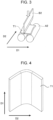
- the bending-orthogonal bending test is performed as described below.
- a steel sheet is subjected to 90-degree bending (primary bending) at a curvature radius/thickness ratio of 4.2 in the rolling (L) direction with respect to an axis extending in the width (C) direction to prepare a test specimen.
- a punch B1 is pressed against a steel sheet on a die A1 with a V-groove to prepare a test specimen T1.
- the test specimen T1 on support rolls A2 is subjected to orthogonal bending (secondary bending) by pressing a punch B2 against the test specimen T1 in the direction perpendicular to the rolling direction.
- D1 denotes the width (C) direction
- D2 denotes the rolling (L) direction.
- Fig. 4 illustrates the test specimen T1 after the steel sheet is subjected to the 90-degree bending (primary bending).
- Fig. 5 illustrates the test specimen T2 after the test specimen T1 is subjected to the orthogonal bending (secondary bending).
- the positions indicated by the broken lines on the test specimen T2 in Fig. 5 correspond to the positions indicated by the broken lines on the test specimen T1 in Fig. 4 before the orthogonal bending.
- the stroke at the maximum load is determined in a stroke-load curve of the orthogonal bending.
- the average stroke ⁇ S at the maximum load is determined by performing the bending-orthogonal bending test three times.
- the axial crushing test is performed as described below.
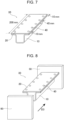
- a steel sheet produced through the production steps described above is cut and formed (bent) to a depth of 40 mm using a die with a punch shoulder radius of 5.0 mm and a die shoulder radius of 5.0 mm to produce a hat-shaped member 10 illustrated in Figs. 6 and 7 .
- the steel sheet used as the material of the hat-shaped member is separately cut into a size of 200 mm x 80 mm.
- a steel sheet 20 thus cut out and the hat-shaped member 10 are spot welded to produce a test member 30 as illustrated in Figs. 6 and 7 .
- FIG. 6 is a front view of the test member 30 produced by spot-welding the hat-shaped member 10 and the steel sheet 20.
- Fig. 7 is a perspective view of the test member 30. As illustrated in Fig. 7 , spot welds 40 are positioned such that the distance between an end portion of the steel sheet and a weld is 10 mm and the distance between the welds is 45 mm.
- the test member 30 is joined to a base plate 50 by TIG welding to prepare a sample for the axial crushing test.
- the prepared axial crushing test sample is collided with an impactor 60 at a constant impact speed of 10 m/s to crush the axial crushing test sample by 100 mm.
- the crushing direction D3 is parallel to the longitudinal direction of the test member 30.
- the area in a crushing stroke-load graph at a stroke in the range of 0 to 100 mm is determined, and the average area of the test performed three times is taken as absorbed energy (F ave ) .
- C facilitates the formation of a phase other than ferrite and forms an alloy compound with Nb, Ti, or the like.
- C is therefore an element necessary for strength improvement. Desired strength may not be achieved at a C content of less than 0.03% even if the production conditions are optimized.
- the C content is preferably 0.03% or more, more preferably 0.05% or more.
- the C content is preferably 0.20% or less, more preferably 0.18% or less.
- Si is a ferrite-forming element and is also a solid-solution strengthening element.
- Si contributes to an improvement in the balance between strength and ductility.
- the Si content is preferably 0.1% or more, more preferably 0.2% or more.
- a Si content of more than 2.0% may result in lower deposition or adhesion in galvanization and poor surface quality.
- the Si content is preferably 2.0% or less, more preferably 1.5% or less.
- Mn is a martensite-forming element and is also a solid-solution strengthening element. Mn contributes to the stabilization of retained austenite. To produce these effects, the Mn content is preferably 0.5% or more. The Mn content is more preferably 1.0% or more. On the other hand, a Mn content of more than 2.5% may result in excessive formation of martensite and poor collision characteristics. Thus, the Mn content is preferably 2.5% or less, more preferably 2.0% or less.
- P is an element effective in strengthening steel.
- a P content of more than 0.05% may result in a much lower alloying rate.
- An excessively high P content of more than 0.05% may result in embrittlement due to grain boundary segregation and result in lower fracture resistance in case of a collision even with a steel microstructure of the present invention.
- the P content is preferably 0.05% or less, more preferably 0.01% or less.
- the P content may have any lower limit, the lower limit industrially applicable at present is 0.002%, the P content is preferably 0.002% or more.
- the S content is preferably as low as possible but is preferably 0.05% or less in terms of production costs.
- the S content is more preferably 0.01% or less.
- the S content may have any lower limit, the lower limit industrially applicable at present is 0.0002%, the S content is preferably 0.0002% or more.
- Al acts as a deoxidizing agent and is also a solid-solution strengthening element.
- a Sol. Al content of less than 0.005% may be insufficient for these effects and may result in lower strength even with a steel microstructure of the present invention.
- the Sol. Al content is preferably 0.005% or more.
- a Sol. Al content of more than 0.1% results in lower slab quality in steelmaking.
- the Sol. Al content is preferably 0.1% or less, more preferably 0.04% or less.
- N forms a coarse inclusion of a nitride or carbonitride, such as TiN, (Nb, Ti)(C, N), or AlN, in steel and impairs collision characteristics.
- a nitride or carbonitride such as TiN, (Nb, Ti)(C, N), or AlN
- the N content should be reduced.
- a N content of more than 0.010% tends to result in poor collision characteristics.
- the N content is preferably 0.010% or less.
- the N content is more preferably 0.007% or less, still more preferably 0.005% or less.
- the N content may have any lower limit, the lower limit industrially applicable at present is 0.0003%, the N content is preferably 0.0003% or more.
- a chemical composition of a steel sheet according to the present invention contains these component elements as base components and the remainder composed of iron (Fe) and incidental impurities.
- a steel sheet according to the present invention preferably has a chemical composition that contains the base components and the remainder composed of iron (Fe) and incidental impurities.
- a steel sheet according to the present invention may contain the following components (optional elements) depending on desired characteristics.
- Cr, Mo, and V are elements that are effective in improving hardenability and strengthening steel.
- the excessive addition of more than 1.0% of Cr, more than 0.5% of Mo, or more than 0.5% of V has saturated effects and further increases the raw material cost. This may also excessively increase the second phase fraction and reduce fracture resistance in case of a collision.
- the Cr content is preferably 1.0% or less, the Mo content is preferably 0.5% or less, and the V content is preferably 0.5% or less. More preferably, the Cr content is 0.8% or less, the Mo content is 0.4% or less, and the V content is 0.4% or less.
- the Cr, Mo, or V content may have any lower limit.
- the Cr, Mo, or V content is preferably 0.005% or more. More preferably, the Cr, Mo, or V content is 0.01% or more.
- Ti and Nb are elements effective for precipitation strengthening of steel.
- a Ti content or a Nb content of more than 0.5% may result in lower fracture resistance in case of a collision.
- the Ti content or the Nb content is preferably 0.5% or less. More preferably, the Ti content or the Nb content is 0.4% or less.
- the advantages of the present invention can be achieved even at a low Ti or Nb content.
- the Ti or Nb content may have any lower limit.
- the Ti content or the Nb content is preferably 0.005% or more. More preferably, the Ti content or the Nb content is 0.01% or more.
- B may be added as required because B prevents the formation and growth of ferrite from an austenite grain boundary and contributes to an improvement in hardenability.
- a B content of more than 0.005% may result in lower fracture resistance in case of a collision.
- the B content is preferably 0.005% or less. More preferably, the B content is 0.004% or less.
- the advantages of the present invention can be achieved even at a low B content.
- the B content may have any lower limit.
- the B content is preferably 0.0003% or more. More preferably, the B content is 0.0005% or more.
- Ni and Cu are elements effective in strengthening steel.
- a Ni or Cu content of more than 1.0% may result in lower fracture resistance in case of a collision.
- the Ni or Cu content is preferably 1.0% or less. More preferably, the Ni content or the Cu content is 0.9% or less.
- the advantages of the present invention can be achieved even at a low Ni or Cu content.
- the Ni or Cu content may have any lower limit.
- the Ni content or the Cu content is preferably 0.005% or more. More preferably, the Ni content or the Cu content is 0.01% or more.
- Sn and Sb may be added as required to reduce nitriding and oxidation of a surface of a steel sheet and decarburization in a region near a surface of a steel sheet. Such prevention of nitriding or oxidation is effective in preventing a decrease in the formation of martensite on a surface of a steel sheet and improving collision characteristics.
- a Sb or Sn content of more than 1.0% may result in poor collision characteristics due to grain boundary embrittlement.
- the Sb content or the Sn content is preferably 1.0% or less. More preferably, the Sb content or the Sn content is 0.9% or less.
- the Sb or Sn content may have any lower limit.
- the Sb content or the Sn content is preferably 0.005% or more. More preferably, the Sb content or the Sn content is 0.01% or more.
- Ca and REM are elements effective in improving workability by morphological control of sulfide.
- a Ca or REM content of more than 0.005% may result in adverse effects on the cleanliness of steel and poor characteristics.
- the Ca or REM content is preferably 0.005% or less. More preferably, the Ca content or the REM content is 0.004% or less.
- the advantages of the present invention can be achieved even at a low Ca or REM content.
- the Ca or REM content may have any lower limit.
- the Ca or REM content is preferably 0.001% or more. More preferably, the Ca content or the REM content is 0.002% or more.
- the temperature at which a steel slab (steel material), a steel sheet, or the like described below is heated or cooled refers to the surface temperature of the steel slab (steel material), the steel sheet, or the like.
- a method for producing a steel sheet according to the present invention includes, for example, a hot-rolling step of hot-rolling a steel slab with such a chemical composition as described above at a finish rolling temperature in the range of 850°C to 950°C and coiling the hot-rolled steel sheet at a coiling temperature of 600°C or less, a cold-rolling step of cold-rolling the hot-rolled steel sheet after the hot-rolling step at a rolling reduction of more than 20%, an annealing step of heating the cold-rolled steel sheet after the cold-rolling step to an annealing temperature in the range of 720°C to 860°C and holding the steel sheet for 30 seconds or more, a quenching step of cooling the steel sheet at an average cooling rate of 20°C/s or more in a temperature range of the annealing temperature to a martensite transformation start temperature Ms and then cooling the steel sheet from the martensite transformation start temperature Ms to a finish cooling temperature in the range of (Ms - 250°C) to
- a method for producing a steel sheet according to the present invention may include a coating step of applying electrogalvanizing, hot-dip galvanizing, or hot-dip galvannealing to a surface of the steel sheet after the tempering step and before the heat-treatment step.
- a steel slab for use in a method for producing a steel sheet according to the present invention has a chemical composition satisfying an equivalent carbon content Ceq of 0.35% or more and less than 0.60%.
- the equivalent carbon content Ceq of 0.35% or more and less than 0.60% is an optimum range for producing a steel sheet according to the present invention under the production conditions of the present invention.
- Finish rolling temperature 850°C to 950°C
- a finish rolling temperature of less than 850°C may result in ferrite transformation while rolling, locally decreased strength, and low strength even with a microstructure of the present invention.
- the finish rolling temperature is 850°C or more, preferably 880°C or more.
- a finish rolling temperature of more than 950°C may result in coarse crystal grains and low strength even with a microstructure of the present invention.
- the finish rolling temperature is 950°C or less, preferably 930°C or less.
- Coiling temperature 600°C or less
- a coiling temperature of more than 600°C may result in coarse carbide in a hot-rolled steel sheet, and such coarse carbide sometimes does not melt completely while soaking in annealing.
- the hot-rolled steel sheet may have insufficient strength.
- the coiling temperature is 600°C or less, preferably 580°C or less.
- the coiling temperature may have any lower limit but is preferably 400°C or more to prevent the formation of a steel sheet in poor shape and an excessively hard steel sheet.
- a hot-rolled steel sheet produced in the hot-rolling step is typically subjected to preliminary treatment, such as pickling or degreasing, by a known method and is then cold-rolled if necessary. Conditions for cold-rolling in the cold-rolling step are described below.
- the rolling reduction in the cold-rolling is 20% or less, recrystallization of ferrite is not promoted, unrecrystallized ferrite remains, and a steel microstructure of the present invention may not be formed.
- the rolling reduction in the cold-rolling is more than 20%, preferably 30% or more.
- Annealing temperature 720°C to 860°C, holding time: 30 seconds or more
- an annealing temperature of less than 720°C results in insufficient austenite formation and excessive ferrite formation.
- the annealing temperature is 720°C or more, preferably 740°C or more.
- the volume fraction of ferrite of the present invention cannot be achieved. This may also result in lower fracture resistance due to excessive bainite.
- the annealing temperature is 860°C or less, preferably 840°C or less.
- a holding time of less than 30 seconds results in insufficient austenite formation and excessive ferrite formation.
- the holding time is 30 seconds or more, preferably 60 seconds or more.
- the holding time may have any upper limit but is preferably 600 seconds or less in terms of productivity.
- quenching is performed. Conditions in the quenching step are described below.
- Average cooling rate in the temperature range of the annealing temperature to the martensite transformation start temperature Ms 20°C/s or more
- the fracture resistance of the present invention cannot be achieved at an average cooling rate of less than 20°C/s.
- the reason is not clear but may be as follows: a cooling rate of less than 20°C/s results in excessive formation of ferrite or bainite while cooling and a lower martensite transformation start temperature Ms. This results in a decrease in the amount of martensite transformation when cooling is stopped, martensite transformation at a lower temperature, and consequently insufficient tempering of martensite while cooling as compared with the case where the Ms temperature is high. This reduces the effect of reducing the hardness difference by the tempered martensite, prevents the tempered martensite from deforming with the ferrite in the primary processing, easily forms a void, and impairs collision characteristics.
- the average cooling rate is 20°C/s or more.
- Each element symbol in the formula represents the element content (% by mass) and is 0 for an element not contained.
- [ ⁇ % by area] represents the ferrite area fraction after annealing.
- the ferrite area fraction after annealing is determined in advance by simulating the heating rate, the annealing temperature, and the holding time for the annealing with a thermodilatometer.
- rapid cooling is preferably performed at the highest possible cooling rate, and the average cooling rate in the temperature range of the annealing temperature to the martensite start transformation temperature Ms is more preferably 30°C/s or more.
- the upper limit of the average cooling rate is preferably, but not limited to, 200°C/s or less in terms of production costs.
- Average cooling rate from martensite transformation start temperature Ms to finish cooling temperature 2°C/s to 15°C/s
- the average cooling rate is 2°C/s or more, preferably 5°C/s or more.
- the fracture resistance of the present invention cannot be achieved. The reason is not clear but may be as follows: a cooling rate of 15°C/s or less results in a longer time from the Ms temperature to the finish cooling temperature, tempering of martensite even while cooling, and a larger effect of reducing the hardness difference by the tempered martensite. This effect cannot be produced at a cooling rate of more than 15°C/s.
- the tempered martensite does not deform with ferrite in the primary processing, a void is easily formed, and collision characteristics are deteriorated.
- the average cooling rate is 15°C/s or less, preferably 10°C/s or less.
- Finish cooling temperature (Ms - 250°C) to (Ms - 50°C)
- the finish cooling temperature is (Ms - 50°C) or less, preferably (Ms - 100°C) or less.
- a finish cooling temperature of less than (Ms - 250°C) may result in excessive tempered martensite and insufficient formation of retained austenite.
- the finish cooling temperature is (Ms - 250°C) or more, preferably (Ms - 200°C) or more.
- tempering is performed. Conditions in the tempering step are described below.
- Tempering temperature 300°C to 500°C, holding time: 20 seconds or more
- the tempering temperature is 300°C or more, preferably 350°C or more.
- the tempering temperature is 500°C or less, preferably 450°C or less.
- the holding time is 20 seconds or more, preferably 30 seconds or more.
- the holding time may have any upper limit but is preferably 500 seconds or less in terms of productivity.
- Holding temperature after the tempering step 100°C to 300°C, holding time: 20 seconds or more
- a method for producing a steel sheet according to the present invention includes the heat-treatment step of holding the steel sheet in the temperature range of 100°C to 300°C for 20 seconds or more after the tempering step.
- a holding temperature of less than 100°C or more than 300°C, or at a holding time of less than 20 seconds a steel microstructure and fracture resistance of the present invention cannot be achieved.
- the reason is not clear but may be as follows: at less than 100°C, martensite formed while cooling after the tempering step is insufficiently tempered, tempered martensite does not deform with ferrite in the primary processing, a void is easily formed, and consequently collision characteristics are deteriorated.
- the holding temperature is 100°C or more, preferably 150°C or more.
- the holding temperature is 300°C or less, preferably 250°C or less.
- the holding time is 20 seconds or more, preferably 30 seconds or more.
- the holding in the temperature range of 100°C to 300°C may be performed after cooling to the temperature range of 100°C to 300°C after the tempering step or may be performed after cooling to less than 100°C after the tempering step and then reheating to the temperature range of 100°C to 300°C.
- the holding temperature may vary in the temperature range described above.
- the cooling rate while cooling may also vary in a specified range without departing from the gist of the present invention.
- a steel sheet may be heat-treated in any facility provided that the thermal history is satisfied.
- electrogalvanizing, hot-dip galvanizing, or hot-dip galvannealing may be applied to a surface of the steel sheet after the tempering step and before the heat-treatment step.
- the electrogalvanizing treatment is preferably performed by passing an electric current in a zinc solution in the temperature range of 50°C to 60°C.
- the hot-dip galvanizing treatment is preferably performed by immersing a steel sheet produced as described above in a galvanizing bath in the temperature range of 440°C to 500°C.
- the coating weight is then preferably adjusted by gas wiping or the like.
- the hot-dip galvanizing treatment step may be followed by an alloying step of performing alloying treatment.
- the zinc coating is preferably held in the temperature range of 450°C to 580°C for 1 to 40 seconds.
- a steel sheet subjected to hot-dip galvanizing treatment or hot-dip galvannealing treatment may be subjected to temper rolling for shape correction, surface roughness adjustment, or the like.
- temper rolling a temper rolling reduction of more than 0.5% may result in lower bendability due to surface hardening.
- the temper rolling reduction is preferably 0.5% or less, more preferably 0.3% or less.
- coating treatment such as resin or oil coating.
- conditions of a production method are not particularly limited but are preferably the following conditions.
- a slab is preferably produced by continuous casting to prevent macrosegregation and may be produced by ingot casting or thin slab casting.
- To hot-roll a slab the slab may be cooled to room temperature and then reheated for hot-rolling.
- a slab may be hot-rolled in a furnace without cooling to room temperature.
- An energy-saving process of hot-rolling a slab immediately after lightly conserving heat is also applicable.
- the slab is preferably heated to 1100°C or more to prevent an increase in rolling force and dissolve carbides.
- a slab is preferably heated to 1300°C or less to prevent an increase in scale loss.
- a rough bar after rough rolling may be heated.
- a continuous rolling process of joining rough bars together and continuously finish-rolling the rough bars is also applicable.
- rolling with lubrication at a friction coefficient in the range of 0.10 to 0.25 is preferably performed in all or part of the passes of finish rolling.
- Scales may be removed by pickling or the like from a steel sheet after coiling. After pickling, cold-rolling, annealing, and galvanization are performed under the conditions described above.
- a member according to the present invention is produced by performing at least one of forming and welding on a steel sheet according to the present invention.
- a method for producing a member according to the present invention includes the step of performing at least one of forming and welding on a steel sheet produced by a method for producing a steel sheet according to the present invention.
- a steel sheet according to the present invention has high strength and good collision characteristics.
- a member produced by using a steel sheet according to the present invention also has high strength, good collision characteristics, and is less likely to be broken in collision deformation.
- a member according to the present invention can be suitably used as an energy-absorbing member in an automotive part.
- the forming may be any typical processing method, such as press forming.
- the welding may be any typical welding, such as spot welding or arc welding.
- a steel with the chemical composition shown in Table 1 was obtained by steelmaking in a vacuum melting furnace and was then bloomed into a steel slab. These steel slabs were heated and subjected to hot-rolling, cold-rolling, annealing, quenching, tempering, and heat treatment under the conditions shown in Table 2 to produce steel sheets. When steel sheets were produced under the conditions shown in Table 2, some of the steel sheets were subjected to coating treatment after the tempering step.
- electrogalvanizing treatment an electric current is passing through a steel sheet immersed in a zinc solution to form an electrogalvanized layer (EG) with a coating weight in the range of 10 to 100 g/m 2 .
- EG electrogalvanized layer
- hot-dip galvanizing treatment a steel sheet was immersed in a coating bath to form a hot-dip galvanized layer (GI) with a coating weight in the range of 10 to 100 g/m 2 .
- GI hot-dip galvanized layer
- an alloying treatment was performed to form a hot-dip galvannealed layer (GA).
- G hot-dip galvannealed layer
- the steel sheets were subjected to skin pass rolling at a rolling reduction of 0.2%, and then the area fractions of ferrite (F), bainite (B), tempered martensite (TM), and retained austenite (RA) were determined by the following method.
- a change in (a grain size in a thickness direction)/(a grain size in a direction perpendicular to the thickness) of tempered martensite in an L cross section in a 0- to 50- ⁇ m region from a surface of a steel sheet on a compression side was also measured by the method described above in 90-degree bending at a curvature radius/thickness ratio of 4.2 in the rolling (L) direction with respect to an axis extending in the width (C) direction.
- the area fraction of each microstructure is measured in the following way. A thickness cross section of a steel sheet cut at a right angle to the rolling direction is polished and etched in 3% by volume nital and is photographed at a quarter thickness position with a scanning electron microscope (SEM) at a magnification of 1500 times in three visual fields. The area fraction of each microstructure is determined from the captured image data using Image-Pro available from Media Cybernetics. The area fraction of each microstructure is the average area fraction of the three visual fields.
- ferrite can be distinguished as black, bainite as black including island-like retained austenite or gray including carbides with the same orientation, tempered martensite as light gray including fine carbides with different orientations, and retained austenite as white.
- the remaining microstructures were determined by subtracting the total area fraction of ferrite (F), bainite (B), tempered martensite (TM), and retained austenite (RA) from 100%, and the remaining microstructures were considered to be pearlite and/or cementite.
- the volume fraction of retained austenite is the ratio of the integrated X-ray diffraction intensity of (200), (220), and (311) planes in fcc iron to the integrated X-ray diffraction intensity of (200), (211), and (220) planes in bcc iron at a quarter thickness.
- the grain size of tempered martensite in the thickness direction and the grain size of the tempered martensite in the direction perpendicular to the thickness were measured in the following way. After polishing a thickness cross section of a steel sheet cut in the rolling direction, an L cross section in a 0- to 50- ⁇ m region from a surface of the steel sheet at a bending top on the compression side was photographed with a scanning electron microscope (SEM) at a magnification of 3000 times in three visual fields.
- SEM scanning electron microscope
- the grain size of tempered martensite in the thickness direction (the length in the thickness direction) and the grain size of the tempered martensite in a direction perpendicular to the thickness (the length in the direction perpendicular to the thickness) were determined from the captured image data using Image-Pro available from Media Cybernetics. Each grain size is calculated by averaging the grain sizes in the three visual fields. This measurement was performed before and after 90-degree bending.
- the tensile strength (TS) was determined by taking a JIS No. 5 test piece for tensile test (JIS Z 2201) from a steel sheet in a direction perpendicular to the rolling direction and performing a tensile test at a strain rate of 10 -3 /s in accordance with JIS Z 2241 (2011). A TS of 590 MPa or more was judged to be acceptable.
- a steel sheet was subjected to 90-degree bending (primary bending) at a curvature radius/thickness ratio of 4.2 in the rolling (L) direction with respect to an axis extending in the width (C) direction to prepare a test specimen.
- a punch B1 was pressed against a steel sheet on a die A1 with a V-groove to prepare a test specimen T1.
- the test specimen T1 on support rolls A2 was subjected to orthogonal bending (secondary bending) by pressing a punch B2 against the test specimen T1 in the direction perpendicular to the rolling direction.
- D1 denotes the width (C) direction
- D2 denotes the rolling (L) direction.
- Fig. 4 illustrates the test specimen T1 after the steel sheet is subjected to the 90-degree bending (primary bending).
- Fig. 5 illustrates the test specimen T2 after the test specimen T1 is subjected to the orthogonal bending (secondary bending).
- the positions indicated by the broken lines on the test specimen T2 in Fig. 5 correspond to the positions indicated by the broken lines on the test specimen T1 in Fig. 4 before the orthogonal bending.
- the stroke at the maximum load was determined in a stroke-load curve of the orthogonal bending.
- the average stroke ⁇ S at the maximum load was determined by performing the bending-orthogonal bending test three times. ⁇ S of 30 mm or more was judged to be high fracture resistance.
- An axial crushing test was performed on steel sheets 1.2 mm in thickness in consideration of the effects of the thickness.
- a steel sheet produced through the production steps described above was cut and formed (bent) to a depth of 40 mm using a die with a punch shoulder radius of 5.0 mm and a die shoulder radius of 5.0 mm to produce a hat-shaped member 10 illustrated in Figs. 6 and 7 .
- the steel sheet used as the material of the hat-shaped member was separately cut into a size of 200 mm x 80 mm.
- a steel sheet 20 thus cut out and the hat-shaped member 10 were spot welded to produce a test member 30 as illustrated in Figs. 6 and 7 .
- FIG. 6 is a front view of the test member 30 produced by spot-welding the hat-shaped member 10 and the steel sheet 20.
- Fig. 7 is a perspective view of the test member 30. As illustrated in Fig. 7 , spot welds 40 were positioned such that the distance between an end portion of the steel sheet and a weld was 10 mm and the distance between the welds was 45 mm. Next, as illustrated in Fig. 8 , the test member 30 was joined to a base plate 50 by TIG welding to prepare a sample for the axial crushing test. Next, the prepared axial crushing test sample was collided with an impactor 60 at a constant impact speed of 10 m/s to crush the axial crushing test sample by 100 mm. As illustrated in Fig.
- the crushing direction D3 was parallel to the longitudinal direction of the test member 30.
- the area in a crushing stroke-load graph at a stroke in the range of 0 to 100 mm was determined, and the average area of the test performed three times was taken as absorbed energy (F ave ).
- F ave of 35000 N or more was judged to be high absorbed energy. Collision characteristics were judged to be good when both fracture resistance and absorbed energy were high.
- the steel sheets according to the examples had a TS of 590 MPa or more and good collision characteristics.
- the steel sheets according to the comparative examples had a TS of less than 590 MPa or poor collision characteristics.
- a steel sheet of No. 3 (Example) in Table 3 of Example 1 was subjected to press forming to produce a member according to an Example.
- the steel sheet of No. 3 in Table 3 of Example 1 and a steel sheet of No. 9 (Example) in Table 3 of Example 1 were joined together by spot welding to produce a member according to an Example. It was confirmed that a member according to an Example produced by using a steel sheet according to the present invention had good collision characteristics and high strength, and that all of the member produced by forming the steel sheet of No. 3 (Example) in Table 3 of Example 1 and the member produced by spot welding the steel sheet of No. 3 in Table 3 of Example 1 and the steel sheet of No. 9 (Example) in Table 3 of Example 1 could be suitably used for automobile frame parts and the like.
- a galvanized steel sheet of No. 1 (Example) in Table 3 of Example 1 was subjected to press forming to produce a member according to an Example.
- the galvanized steel sheet of No. 1 in Table 3 of Example 1 and a galvanized steel sheet of No. 4 (Example) in Table 3 of Example 1 were joined together by spot welding to produce a member according to an Example. It was confirmed that a member according to an Example produced by using a steel sheet according to the present invention had good collision characteristics and high strength, and that all of the member produced by forming the steel sheet of No. 1 (Example) in Table 3 of Example 1 and the member produced by spot welding the steel sheet of No. 1 in Table 3 of Example 1 and the steel sheet of No. 4 (Example) in Table 3 of Example 1 could be suitably used for automobile frame parts and the like.
- the present invention can provide a steel sheet with a TS of 590 MPa or more and with good collision characteristics.
- the use of a member produced by using a steel sheet according to the present invention as an automotive part can contribute to the reduction of vehicle weight and greatly contribute to improved performance of automobile bodies.
Landscapes
- Chemical & Material Sciences (AREA)
- Engineering & Computer Science (AREA)
- Materials Engineering (AREA)
- Mechanical Engineering (AREA)
- Metallurgy (AREA)
- Organic Chemistry (AREA)
- Physics & Mathematics (AREA)
- Thermal Sciences (AREA)
- Crystallography & Structural Chemistry (AREA)
- Chemical Kinetics & Catalysis (AREA)
- Heat Treatment Of Sheet Steel (AREA)
Abstract
Description
- The present invention relates to a high-strength steel sheet or member with good collision characteristics and a method for producing the steel sheet or member. A steel sheet according to the present invention can be suitably used for parts mainly used in the automotive field.
- To reduce CO2 emissions from the perspective of global environmental conservation, it is always important in the automobile industry to reduce the weights of automobile bodies while maintaining their strength and improve mileage. To reduce the weights of automobile bodies while maintaining their strength, it is effective to increase strength of steel sheets used as materials for automotive parts and thereby reduce the thickness of the steel sheets. On the other hand, automotive parts made of steel sheets are required to ensure the safety of occupants in the automobile in case of a collision. Thus, high-strength steel sheets used as materials for automotive parts are required to have good collision characteristics as well as desired strength.
- In recent years, high-strength steel sheets have been increasingly applied to automobile bodies. From the perspective of collision characteristics, automotive parts are broadly divided into non-deformable members, such as pillars and bumpers, and energy-absorbing members, such as side members. These members should have collision characteristics necessary to ensure the safety of occupants in a moving automobile in case of a collision. Strength of non-deformable members have been increased, and high-strength steel sheets with a tensile strength (hereinafter also referred to simply as TS) of 980 MPa or more have already been practically used. However, energy-absorbing members have not been significantly increased strength, and the strength level of practical steel is a TS of approximately 590 MPa or less. One reason for little increase of strength is member fracture in collision deformation. In case of a collision, high-tensile-strength steel tends to cause a member fracture originating from a portion subjected to primary processing of forming and cannot consistently absorb collision energy. Thus, there is room for preventing member fracture in case of a collision, consistently exhibiting high energy absorption to ensure safety in case of a collision, and reducing weight to contribute to environmental conservation. Thus, a high-strength steel sheet with good collision characteristics and with a TS of 590 MPa or more should be applied to an energy-absorbing member.
- To address such a need, for example,
Patent Literature 1 discloses a technique related to an ultra-high-strength steel sheet with high formability and impact resistance and with a TS of 1200 MPa. Patent Literature 2 discloses a technique related to a high-strength steel sheet with a maximum tensile strength of 780 MPa or more applicable to an impact-absorbing member in case of a collision. -
- PTL 1:
Japanese Unexamined Patent Application Publication No. 2012-31462 - PTL 2:
Japanese Unexamined Patent Application Publication No. 2015-175061 - Although collision characteristics are examined in
Patent Literature 1, impact resistance is examined on the assumption that a member is not broken in case of a collision, and collision characteristics are not examined from the perspective of member fracture resistance. - In Patent Literature 2, a dynamic axial crushing test with a falling weight is performed on a hat-shaped member to evaluate cracking and fracture resistance at a TS of more than 780 MPa. However, rating cracking after crushing cannot evaluate the process from the initiation of a crack during the crushing to the fracture, which is important for collision characteristics. This is because, if a crack occurs early in the process of crushing, even a small crack that does not passes through the sheet may reduce absorbing energy. Furthermore, if a crack occurs in the later stage in the process of crushing, even a large crack that passes through the sheet may have little effect on absorbing energy. Thus, only rating cracking after crushing is probably insufficient for the evaluation of fracture resistance.
- In view of such situations, it is an object of the present invention to provide a steel sheet or member with a tensile strength (TS) of 590 MPa or more and with good collision characteristics suitable for an energy-absorbing member of an automobile and a method for producing the steel sheet or member.
- As a result of extensive studies to solve the above problems, the present inventors have found the following.
- A steel sheet has a chemical composition satisfying an equivalent carbon content Ceq of 0.35% or more and less than 0.60% and a steel microstructure with an area fraction of ferrite: 40% to 85%, tempered martensite and bainite: 10% to 55% in total, retained austenite: 3% to 15%, and ferrite, tempered martensite, bainite, and retained austenite: 93% or more in total, wherein specified 90-degree bending of the steel sheet causes a change of 0.50 or more in (a grain size in a thickness direction)/(a grain size in a direction perpendicular to the thickness) of the tempered martensite in an L cross section in a 0- to 50-µm region from a surface of the steel sheet on a compression side. It has been found that these can provide a high-strength steel sheet with good collision characteristics.
- The present invention has been accomplished on the basis of these findings, and the summary of the present invention is described below.
- [1] A steel sheet having
- a chemical composition satisfying an equivalent carbon content Ceq of 0.35% or more and less than 0.60%, and
- a steel microstructure with an area fraction of ferrite: 40% to 85%, tempered martensite and bainite: 10% to 55% in total, retained austenite: 3% to 15%, and ferrite, tempered martensite, bainite, and retained austenite: 93% or more in total,
- wherein 90-degree bending at a curvature radius/thickness ratio of 4.2 in a rolling (L) direction with respect to an axis extending in a width (C) direction causes a change of 0.50 or more in (a grain size in a thickness direction)/(a grain size in a direction perpendicular to the thickness) of the tempered martensite in an L cross section in a 0- to 50-µm region from a surface of the steel sheet on a compression side, and
- the steel sheet has a tensile strength of 590 MPa or more.
- [2] The steel sheet according to [1], wherein the chemical composition contains, on a mass percent basis,
- C: 0.03% to 0.20%,
- Si: 0.1% to 2.0%,
- Mn: 0.5% to 2.5%,
- P: 0.05% or less,
- S: 0.05% or less,
- Sol. Al: 0.005% to 0.1%, and
- N: 0.010% or less, a remainder being composed of Fe and incidental impurities.
- [3] The steel sheet according to [2], wherein the chemical composition further contains, on a mass percent basis,
- at least one selected from
- Cr: 1.0% or less,
- Mo: 0.5% or less,
- V: 0.5% or less,
- Ti: 0.5% or less,
- Nb: 0.5% or less,
- B: 0.005% or less,
- Ni: 1.0% or less,
- Cu: 1.0% or less,
- Sb: 1.0% or less,
- Sn: 1.0% or less,
- Ca: 0.005% or less, and
- REM: 0.005% or less.
- [4] The steel sheet according to any one of [1] to [3], having an electrogalvanized layer, a hot-dip galvanized layer, or a hot-dip galvannealed layer on a surface thereof.
- [5] A member produced by performing at least one of forming and welding on the steel sheet according to any one of [1] to [4] .
- [6] A method for producing a steel sheet, including:
- a hot-rolling step of hot-rolling a steel slab satisfying an equivalent carbon content Ceq of 0.35% or more and less than 0.60% and having the chemical composition according to [2] or [3] at a finish rolling temperature in the range of 850°C to 950°C and coiling the resulting hot-rolled steel sheet at a coiling temperature of 600°C or less;
- a cold-rolling step of cold-rolling the hot-rolled steel sheet after the hot-rolling step at a rolling reduction of more than 20%;
- an annealing step of heating the cold-rolled steel sheet after the cold-rolling step to an annealing temperature in the range of 720°C to 860°C and holding the steel sheet for 30 seconds or more;
- a quenching step of cooling the steel sheet at an average cooling rate of 20°C/s or more in a temperature range of the annealing temperature to a martensite transformation start temperature Ms and then cooling the steel sheet from the martensite transformation start temperature Ms to a finish cooling temperature in the range of (Ms - 250°C) to (Ms - 50°C) at an average cooling rate in the range of 2°C/s to 15°C/s;
- a tempering step of holding the steel sheet in the temperature range of 300°C to 500°C for 20 seconds or more; and
- a heat-treatment step of holding the steel sheet in the temperature range of 100°C to 300°C for 20 seconds or more after the tempering step.
- [7] The method for producing a steel sheet according to [6], including a coating step of applying electrogalvanizing, hot-dip galvanizing, or hot-dip galvannealing to a surface of the steel sheet after the tempering step and before the heat-treatment step.
- [8] A method for producing a member, including the step of performing at least one of forming and welding on a steel sheet produced by the method for producing a steel sheet according to [6] or [7].
- The present invention can provide a steel sheet with a tensile strength (TS) of 590 MPa or more and with good collision characteristics. A member produced by performing forming, welding, or the like on a steel sheet according to the present invention can be suitably used as an energy-absorbing member used in the automotive field.
-
- [
Fig. 1] Fig. 1 is an explanatory view of a steel sheet after 90-degree bending (primary bending). - [
Fig. 2] Fig. 2 is an explanatory view of the 90-degree bending (primary bending) in a bending-orthogonal bending test in Examples. - [
Fig. 3] Fig. 3 is an explanatory view of orthogonal bending (secondary bending) in a bending-orthogonal bending test in Examples. - [
Fig. 4] Fig. 4 is a perspective view of a test specimen subjected to the 90-degree bending (primary bending). - [
Fig. 5] Fig. 5 is a perspective view of a test specimen subjected to the orthogonal bending (secondary bending). - [
Fig. 6] Fig. 6 is a front view of a test member composed of a hat-shaped member and a steel sheet spot welded together for an axial crushing test in Examples. - [
Fig. 7] Fig. 7 is a perspective view of the test member illustrated inFig. 6 . - [
Fig. 8] Fig. 8 is a schematic explanatory view of an axial crushing test in Examples. - The present invention is described in detail below.
- A steel sheet according to the present invention has
- a chemical composition satisfying an equivalent carbon content Ceq of 0.35% or more and less than 0.60%, and
- a steel microstructure with an area fraction of ferrite: 40% to 85%, tempered martensite and bainite: 10% to 55% in total, retained austenite: 3% to 15%, and ferrite, tempered martensite, bainite, and retained austenite: 93% or more in total.
- The equivalent carbon content Ceq refers to the effects of elements other than C converted into the C content as a measure of the strength of steel. Setting the equivalent carbon content Ceq to 0.35% or more and less than 0.60% allows the area fraction of each metallic microstructure, such as ferrite, described later to be controlled within the scope of the present invention. Setting the equivalent carbon content Ceq to 0.35% or more, preferably 0.40% or more, can provide the strength of the present invention. On the other hand, setting the equivalent carbon content Ceq to less than 0.60%, preferably 0.55% or less, can produce the effect of improving collision characteristics in the present invention.
- The equivalent carbon content Ceq can be determined using the following formula.

- The [element symbol %] in the formula represents the element content (% by mass) and is 0 for an element not contained.
- An area fraction of ferrite of less than 40% may result in an excessive volume fraction of tempered martensite and poor collision characteristics. Thus, the area fraction of ferrite is 40% or more, preferably 50% or more. On the other hand, an area fraction of ferrite of more than 85% may result in an excessive volume fraction of ferrite and a lower TS. Thus, the area fraction of ferrite is 85% or less, preferably 80% or less, more preferably 75% or less, still more preferably 70% or less.
- Tempered martensite and bainite are effective in reducing member fracture in collision deformation, improving absorbing energy, and increasing strength. A total area fraction of tempered martensite and bainite of less than 10% may result in a lower TS. Thus, the total area fraction is 10% or more, preferably 20% or more. A total area fraction of tempered martensite and bainite of more than 55% may result in poor collision characteristics. Thus, the total area fraction is 55% or less, preferably 50% or less.
- Although each of tempered martensite and bainite may have any area fraction in the above range, the area fraction of bainite preferably ranges from 3% to 20%. The reason for this preferred range may be as follows: bainite is effective in concentrating C in untransformed austenite during the holding in the tempering step and forming retained austenite and in improving absorbed energy in case of a collision. Such effects may be small at an area fraction of bainite of less than 3%. On the other hand, an area fraction of bainite of more than 20% results in excessive concentration of C in untransformed austenite during the holding in the tempering step and a decrease in martensite transformation start temperature Ms (hereinafter also referred to simply as an Ms temperature or Ms). Thus, martensite formed during the cooling after the holding has a high solute C content, and martensite transformation occurs at a lower temperature. Thus, tempering of martensite during the cooling is insufficient compared with the case where the Ms temperature is higher. This reduces the effect of reducing the hardness difference by the tempered martensite, prevents the tempered martensite from deforming with the ferrite in the primary processing, easily forms a void, and sometimes impairs collision characteristics. Thus, the area fraction of bainite is preferably 3% or more. The area fraction of bainite is preferably 20% or less.
- The area fraction of bainite is more preferably 5% or more, still more preferably 8% or more. The area fraction of bainite is more preferably 18% or less, still more preferably 15% or less.
- Retained austenite is effective in retarding cracking in case of a collision and improving collision characteristics. The mechanism is not clear but may be as follows: retained austenite is work-hardened in collision deformation, increases the curvature radius in bending deformation, and disperses strain in a bent portion. The dispersion of strain reduces stress concentration in a void forming portion in the primary processing and consequently improves collision characteristics. Such effects cannot be produced at an area fraction of retained austenite of less than 3%. Furthermore, the TS may decrease. Thus, the area fraction of retained austenite is 3% or more, preferably 5% or more. On the other hand, an area fraction of retained austenite of more than 15% may result in lower fracture resistance in case of a collision due to fresh martensite formed by deformation-induced transformation. Thus, the area fraction of retained austenite is 15% or less, preferably 10% or less.
- A total area fraction of ferrite, tempered martensite, bainite, and retained austenite of less than 93% results in an increased area fraction of a phase other than these phases and makes it difficult to satisfy both the strength and collision characteristics. The other phase is, for example, fresh martensite, pearlite, or cementite, and a total of more than 7% of these phases may act as a starting point of void formation in collision deformation and impair collision characteristics. An increase in the area fraction of pearlite or cementite may result in a decrease in strength. A total area fraction of ferrite, tempered martensite, bainite, and retained austenite of 93% or more results in high strength and good collision characteristics regardless of the type or area fraction of the residual phase(s). Thus, the total area fraction is 93% or more, preferably 95% or more. The total area fraction may be 100%. The remaining microstructures may be pearlite and cementite, and the total area fraction of the remaining microstructures is 7% or less. The total area fraction of the remaining microstructures is preferably 5% or less.
- The area fraction of ferrite, tempered martensite, and bainite refers to the ratio of the area of each phase to the observed area. The area fraction of each microstructure is measured in the following way. A thickness cross section of a steel sheet cut at a right angle to the rolling direction is polished and etched in 3% by volume nital and is photographed at a quarter thickness position with a scanning electron microscope (SEM) at a magnification of 1500 times in three visual fields. The area fraction of each microstructure is determined from the captured image data using Image-Pro available from Media Cybernetics. The area fraction of each microstructure is the average area fraction of the three visual fields. In the image data, ferrite can be distinguished as black, bainite as black including island-like retained austenite or gray including carbides with the same orientation, tempered martensite as light gray including fine carbides with different orientations, and retained austenite as white.
- In the present invention, the X-ray diffraction intensity described below is measured to determine the volume fraction of retained austenite, and the volume fraction is regarded as the area fraction of retained austenite. The volume fraction of retained austenite is the ratio of the integrated X-ray diffraction intensity of (200), (220), and (311) planes in fcc iron to the integrated X-ray diffraction intensity of (200), (211), and (220) planes in bcc iron at a quarter thickness.
- 90-degree bending at a curvature radius/thickness ratio of 4.2 in a rolling (L) direction with respect to an axis extending in a width (C) direction causes a change of 0.50 or more in (a grain size in a thickness direction)/(a grain size in a direction perpendicular to the thickness) of the tempered martensite in an L cross section in a 0- to 50-µm region from a surface of the steel sheet on a compression side
- In a steel sheet according to the present invention, good collision characteristics can be achieved by setting the amount of change in (a grain size in a thickness direction)/(a grain size in a direction perpendicular to the thickness) of tempered martensite due to bending to 0.50 or more. The mechanism is not clear but may be as follows: a member fracture in case of a collision responsible for deterioration of collision characteristics starts from the formation and propagation of a crack. It is thought that a crack tends to occur due to lower work hardening ability and the formation or linking of voids in a region with a large hardness difference. Furthermore, in a collision of an actual member, a portion subjected to the primary processing deforms so as to be bent back in a direction perpendicular to the primary processing. A void formed in a region with a large hardness difference subjected to the primary processing concentrates stress around the void, promotes the formation and propagation of a crack, and finally causes a fracture. Thus, martensite is tempered to decrease a region with a large hardness difference, and the formation of a void in a primary processed portion is reduced by plastic deformation with a soft ferrite phase during bending deformation. Furthermore, if necessary, retained austenite is used to reduce stress concentration in the primary processed portion during deformation and reduce the propagation of a crack from a void. This can prevent member fracture and achieve good collision characteristics. To produce these effects, the amount of change in (a grain size in a thickness direction)/(a grain size in a direction perpendicular to the thickness) of tempered martensite due to bending is 0.50 or more.
- The amount of change can be achieved, for example, by controlling the cooling rate after annealing and by heat treatment after the tempering step in a production method described later. In the temperature range of the annealing temperature to the martensite transformation start temperature (hereinafter also referred to simply as an Ms temperature or Ms), the cooling rate is increased to reduce ferrite transformation while cooling and reduce the decrease in the Ms temperature. In the temperature range of the Ms temperature to the finish cooling temperature, martensite formed by decreasing the cooling rate is tempered even while cooling. It is thought that softened tempered martensite thus formed deforms plastically with ferrite while bending and reduces the formation of a void. It is also thought that martensite formed after the tempering step becomes tempered martensite, which reduces void formation due to plastic deformation, while maintaining some strength in a predetermined temperature range (100°C to 300°C), and stably has high absorbing energy.
- The amount of change in (a grain size in a thickness direction)/(a grain size in a direction perpendicular to the thickness) of tempered martensite due to bending is determined by the following measurement method.
- First, before a steel sheet is subjected to 90-degree bending, the grain size of tempered martensite in the thickness direction (hereinafter also referred to as a "grain size a1") and the grain size of the tempered martensite in a direction perpendicular to the thickness (hereinafter also referred to as a "grain size a2") are measured in an L cross section in a 0- to 50-µm region from a surface of the steel sheet.
- Next, after the steel sheet is subjected to 90-degree bending at a curvature radius/thickness ratio of 4.2 in the rolling (L) direction with respect to an axis extending in the width (C) direction, the grain size of the tempered martensite in the thickness direction (hereinafter also referred to as a "grain size b1") and the grain size of the tempered martensite in a direction perpendicular to the thickness (hereinafter also referred to as a "grain size b2") are measured in an L cross section in a 0- to 50-µm region from a surface of the steel sheet on the compression side.
- The measurement position of the grain size after bending in the rolling direction is in a region including a corner formed by the bending and extending in the width (C) direction (see the reference letter D1 in
Fig. 1 ). More specifically, in a region that becomes the lowest portion in the width direction and in a direction perpendicular to the rolling direction (a pressing direction of a pressing portion, such as a punch) by bending, the grain size of the tempered martensite is measured in a 0- to 50-µm region in the thickness direction. - In the present invention, the amount of change in (a grain size in a thickness direction)/(a grain size in a direction perpendicular to the thickness) of tempered martensite due to bending is calculated by "(grain size b1/grain size b2) - (grain size a1/grain size a2)".
- The grain size of tempered martensite in the thickness direction and the grain size of the tempered martensite in the direction perpendicular to the thickness are measured in the following way. After polishing a thickness cross section of a steel sheet cut in the rolling direction, an L cross section in a 0- to 50-µm region from a surface of the steel sheet at a bending top on the compression side is photographed with a scanning electron microscope (SEM) at a magnification of 3000 times in three visual fields. The grain size of tempered martensite in the thickness direction (the length in the thickness direction) and the grain size of the tempered martensite in a direction perpendicular to the thickness (the length in the direction perpendicular to the thickness) are determined from the captured image data using Image-Pro available from Media Cybernetics. Each grain size is calculated by averaging the grain sizes in the three visual fields. This measurement is performed before and after 90-degree bending.
- In the present invention, performing 90-degree bending in the rolling (L) direction with respect to an axis extending in the width (C) direction refers to bending a steel sheet by pressing a surface of the steel sheet in a direction perpendicular to the width direction and the rolling direction (see the reference letters D1 and D2 in
Fig. 1 ) such that the distance between both end portions is shortened when the steel sheet is viewed in the width (C) direction (see the reference letter D1 inFig. 1 ) (when a steel sheet is viewed in the width direction (in a vertical cross-sectional view in the width direction)), and pressing the steel sheet such that the angle between flat portions of the end portions not subjected to bending is 90 degrees. - A surface of a steel sheet on the compression side refers to a surface of the steel sheet to be pressed as described above (a surface of the steel sheet in contact with a pressing portion, such as a punch).
- An L cross section before bending refers to a cross section parallel to the rolling direction and perpendicular to a surface of a steel sheet (a cross section perpendicular to the width direction).
- An L cross section after bending refers to a cross section that is formed by cutting parallel to the direction of deformation caused by bending and that is perpendicular to the width direction.
- 90-degree bending can be bending by a V-block method, bending by drawing, or the like.
- A steel sheet according to the present invention may have an electrogalvanized layer, a hot-dip galvanized layer, or a hot-dip galvannealed layer on a surface thereof.
- A steel sheet according to the present invention has a tensile strength (TS) of 590 MPa or more. The term "high strength", as used herein, refers to a tensile strength (TS) of 590 MPa or more. The upper limit of tensile strength (TS) is preferably, but not limited to, less than 980 MPa, in terms of the balance with other characteristics. The tensile strength (TS) is determined by taking a JIS No. 5 test piece for tensile test (JIS Z 2201) from a steel sheet in a direction perpendicular to the rolling direction and performing a tensile test at a strain rate of 10-3 /s in accordance with JIS Z 2241 (2011).
- A steel sheet according to the present invention preferably has a thickness in the range of 0.2 to 3.2 mm in order to effectively achieve the advantages of the present invention.
- A steel sheet according to the present invention has good collision characteristics. The term "good collision characteristics", as used herein, refers to high fracture resistance and absorbing energy. The term "good fracture resistance", as used herein, refers to an average stroke ΔS of 30 mm or more at the maximum load in a bending-orthogonal bending test described later. The term "good collision characteristics", as used herein, refers to an average area Fave of 35000 N or more at a stroke in the range of 0 to 100 mm in a crushing stroke-load graph in an axial crushing test described later.
- The bending-orthogonal bending test is performed as described below.
- First, a steel sheet is subjected to 90-degree bending (primary bending) at a curvature radius/thickness ratio of 4.2 in the rolling (L) direction with respect to an axis extending in the width (C) direction to prepare a test specimen. In the 90-degree bending (primary bending), as illustrated in
Fig. 2 , a punch B1 is pressed against a steel sheet on a die A1 with a V-groove to prepare a test specimen T1. Next, as illustrated inFig. 3 , the test specimen T1 on support rolls A2 is subjected to orthogonal bending (secondary bending) by pressing a punch B2 against the test specimen T1 in the direction perpendicular to the rolling direction. InFigs. 2 and3 , D1 denotes the width (C) direction, and D2 denotes the rolling (L) direction. -
Fig. 4 illustrates the test specimen T1 after the steel sheet is subjected to the 90-degree bending (primary bending).Fig. 5 illustrates the test specimen T2 after the test specimen T1 is subjected to the orthogonal bending (secondary bending). The positions indicated by the broken lines on the test specimen T2 inFig. 5 correspond to the positions indicated by the broken lines on the test specimen T1 inFig. 4 before the orthogonal bending. - The conditions for the orthogonal bending are as follows:
-
- Test method: roll support, punch pressing
- Roll diameter: φ30 mm
- Punch tip R: 0.4 mm
- Distance between rolls: (sheet thickness x 2) + 0.5 mm
- Stroke speed: 20 mm/min
- Test specimen size: 60 mm x 60 mm
- Bending direction: a direction perpendicular to the rolling direction
- The stroke at the maximum load is determined in a stroke-load curve of the orthogonal bending. The average stroke ΔS at the maximum load is determined by performing the bending-orthogonal bending test three times.
- The axial crushing test is performed as described below.
- First, the axial crushing tests are all performed on steel sheets 1.2 mm in thickness in consideration of the effects of the thickness. A steel sheet produced through the production steps described above is cut and formed (bent) to a depth of 40 mm using a die with a punch shoulder radius of 5.0 mm and a die shoulder radius of 5.0 mm to produce a hat-shaped
member 10 illustrated inFigs. 6 and7 . The steel sheet used as the material of the hat-shaped member is separately cut into a size of 200 mm x 80 mm. Next, asteel sheet 20 thus cut out and the hat-shapedmember 10 are spot welded to produce atest member 30 as illustrated inFigs. 6 and7 .Fig. 6 is a front view of thetest member 30 produced by spot-welding the hat-shapedmember 10 and thesteel sheet 20.Fig. 7 is a perspective view of thetest member 30. As illustrated inFig. 7 ,spot welds 40 are positioned such that the distance between an end portion of the steel sheet and a weld is 10 mm and the distance between the welds is 45 mm. Next, as illustrated inFig. 8 , thetest member 30 is joined to abase plate 50 by TIG welding to prepare a sample for the axial crushing test. Next, the prepared axial crushing test sample is collided with an impactor 60 at a constant impact speed of 10 m/s to crush the axial crushing test sample by 100 mm. As illustrated inFig. 8 , the crushing direction D3 is parallel to the longitudinal direction of thetest member 30. The area in a crushing stroke-load graph at a stroke in the range of 0 to 100 mm is determined, and the average area of the test performed three times is taken as absorbed energy (Fave) . - Next, preferred ranges in the chemical composition of a steel sheet are described. Unless otherwise specified, "%" representing the component element content refers to "% by mass".
- C facilitates the formation of a phase other than ferrite and forms an alloy compound with Nb, Ti, or the like. C is therefore an element necessary for strength improvement. Desired strength may not be achieved at a C content of less than 0.03% even if the production conditions are optimized. Thus, the C content is preferably 0.03% or more, more preferably 0.05% or more. At a C content of more than 0.20%, however, the strength of martensite increases excessively, and the collision characteristics of the present invention may not be achieved even if the production conditions are optimized. Thus, the C content is preferably 0.20% or less, more preferably 0.18% or less.
- Si is a ferrite-forming element and is also a solid-solution strengthening element. Thus, Si contributes to an improvement in the balance between strength and ductility. To produce this effect, the Si content is preferably 0.1% or more, more preferably 0.2% or more. On the other hand, a Si content of more than 2.0% may result in lower deposition or adhesion in galvanization and poor surface quality. Thus, the Si content is preferably 2.0% or less, more preferably 1.5% or less.
- Mn is a martensite-forming element and is also a solid-solution strengthening element. Mn contributes to the stabilization of retained austenite. To produce these effects, the Mn content is preferably 0.5% or more. The Mn content is more preferably 1.0% or more. On the other hand, a Mn content of more than 2.5% may result in excessive formation of martensite and poor collision characteristics. Thus, the Mn content is preferably 2.5% or less, more preferably 2.0% or less.
- P is an element effective in strengthening steel. However, a P content of more than 0.05% may result in a much lower alloying rate. An excessively high P content of more than 0.05% may result in embrittlement due to grain boundary segregation and result in lower fracture resistance in case of a collision even with a steel microstructure of the present invention. Thus, the P content is preferably 0.05% or less, more preferably 0.01% or less. Although the P content may have any lower limit, the lower limit industrially applicable at present is 0.002%, the P content is preferably 0.002% or more.
- S forms an inclusion MnS or the like, causes a crack in a weld along the metal flow, and may impair collision characteristics even with a steel microstructure of the present invention. Thus, the S content is preferably as low as possible but is preferably 0.05% or less in terms of production costs. The S content is more preferably 0.01% or less. Although the S content may have any lower limit, the lower limit industrially applicable at present is 0.0002%, the S content is preferably 0.0002% or more.
- Al acts as a deoxidizing agent and is also a solid-solution strengthening element. A Sol. Al content of less than 0.005% may be insufficient for these effects and may result in lower strength even with a steel microstructure of the present invention. Thus, the Sol. Al content is preferably 0.005% or more. On the other hand, a Sol. Al content of more than 0.1% results in lower slab quality in steelmaking. Thus, the Sol. Al content is preferably 0.1% or less, more preferably 0.04% or less.
- N forms a coarse inclusion of a nitride or carbonitride, such as TiN, (Nb, Ti)(C, N), or AlN, in steel and impairs collision characteristics. Thus, the N content should be reduced. A N content of more than 0.010% tends to result in poor collision characteristics. Thus, the N content is preferably 0.010% or less. The N content is more preferably 0.007% or less, still more preferably 0.005% or less. Although the N content may have any lower limit, the lower limit industrially applicable at present is 0.0003%, the N content is preferably 0.0003% or more.
- A chemical composition of a steel sheet according to the present invention contains these component elements as base components and the remainder composed of iron (Fe) and incidental impurities. A steel sheet according to the present invention preferably has a chemical composition that contains the base components and the remainder composed of iron (Fe) and incidental impurities.
- A steel sheet according to the present invention may contain the following components (optional elements) depending on desired characteristics.
- At least one selected from Cr: 1.0% or less, Mo: 0.5% or less, V: 0.5% or less, Ti: 0.5% or less, Nb: 0.5% or less, B: 0.005% or less, Ni: 1.0% or less, Cu: 1.0% or less, Sb: 1.0% or less, Sn: 1.0% or less, Ca: 0.005% or less, and REM: 0.005% or less
- Cr, Mo, and V are elements that are effective in improving hardenability and strengthening steel. However, the excessive addition of more than 1.0% of Cr, more than 0.5% of Mo, or more than 0.5% of V has saturated effects and further increases the raw material cost. This may also excessively increase the second phase fraction and reduce fracture resistance in case of a collision. Thus, when any one of Cr, Mo, and V is contained, the Cr content is preferably 1.0% or less, the Mo content is preferably 0.5% or less, and the V content is preferably 0.5% or less. More preferably, the Cr content is 0.8% or less, the Mo content is 0.4% or less, and the V content is 0.4% or less. The advantages of the present invention can be achieved even at a low Cr, Mo, or V content. Thus, the Cr, Mo, or V content may have any lower limit. To more effectively produce the effects of hardenability, the Cr, Mo, or V content is preferably 0.005% or more. More preferably, the Cr, Mo, or V content is 0.01% or more.
- Ti and Nb are elements effective for precipitation strengthening of steel. However, a Ti content or a Nb content of more than 0.5% may result in lower fracture resistance in case of a collision. Thus, when either Ti or Nb is contained, the Ti content or the Nb content is preferably 0.5% or less. More preferably, the Ti content or the Nb content is 0.4% or less. The advantages of the present invention can be achieved even at a low Ti or Nb content. Thus, the Ti or Nb content may have any lower limit. To more effectively produce the effects of precipitation strengthening of steel, the Ti content or the Nb content is preferably 0.005% or more. More preferably, the Ti content or the Nb content is 0.01% or more.
- B may be added as required because B prevents the formation and growth of ferrite from an austenite grain boundary and contributes to an improvement in hardenability. However, a B content of more than 0.005% may result in lower fracture resistance in case of a collision. Thus, when B is contained, the B content is preferably 0.005% or less. More preferably, the B content is 0.004% or less. The advantages of the present invention can be achieved even at a low B content. Thus, the B content may have any lower limit. To more effectively produce the effects of improving hardenability, the B content is preferably 0.0003% or more. More preferably, the B content is 0.0005% or more.
- Ni and Cu are elements effective in strengthening steel. However, a Ni or Cu content of more than 1.0% may result in lower fracture resistance in case of a collision. Thus, when Ni or Cu is contained, the Ni or Cu content is preferably 1.0% or less. More preferably, the Ni content or the Cu content is 0.9% or less. The advantages of the present invention can be achieved even at a low Ni or Cu content. Thus, the Ni or Cu content may have any lower limit. To more effectively produce the effects of strengthening steel, the Ni content or the Cu content is preferably 0.005% or more. More preferably, the Ni content or the Cu content is 0.01% or more.
- Sn and Sb may be added as required to reduce nitriding and oxidation of a surface of a steel sheet and decarburization in a region near a surface of a steel sheet. Such prevention of nitriding or oxidation is effective in preventing a decrease in the formation of martensite on a surface of a steel sheet and improving collision characteristics. However, a Sb or Sn content of more than 1.0% may result in poor collision characteristics due to grain boundary embrittlement. Thus, when Sb or Sn is contained, the Sb content or the Sn content is preferably 1.0% or less. More preferably, the Sb content or the Sn content is 0.9% or less. The advantages of the present invention can be achieved even at a low Sb or Sn content. Thus, the Sb or Sn content may have any lower limit. To more effectively produce the effects of improving collision characteristics, the Sb content or the Sn content is preferably 0.005% or more. More preferably, the Sb content or the Sn content is 0.01% or more.
- Ca and REM are elements effective in improving workability by morphological control of sulfide. However, a Ca or REM content of more than 0.005% may result in adverse effects on the cleanliness of steel and poor characteristics. Thus, when Ca or REM is contained, the Ca or REM content is preferably 0.005% or less. More preferably, the Ca content or the REM content is 0.004% or less. The advantages of the present invention can be achieved even at a low Ca or REM content. Thus, the Ca or REM content may have any lower limit. To more effectively produce the effects of improving workability, the Ca or REM content is preferably 0.001% or more. More preferably, the Ca content or the REM content is 0.002% or more.
- These optional elements, if contained below the appropriate lower limits described above, are contained as incidental impurities.
- An embodiment of a method for producing a steel sheet according to the present invention is described in detail below. Unless otherwise specified, the temperature at which a steel slab (steel material), a steel sheet, or the like described below is heated or cooled refers to the surface temperature of the steel slab (steel material), the steel sheet, or the like.
- A method for producing a steel sheet according to the present invention includes, for example, a hot-rolling step of hot-rolling a steel slab with such a chemical composition as described above at a finish rolling temperature in the range of 850°C to 950°C and coiling the hot-rolled steel sheet at a coiling temperature of 600°C or less, a cold-rolling step of cold-rolling the hot-rolled steel sheet after the hot-rolling step at a rolling reduction of more than 20%, an annealing step of heating the cold-rolled steel sheet after the cold-rolling step to an annealing temperature in the range of 720°C to 860°C and holding the steel sheet for 30 seconds or more, a quenching step of cooling the steel sheet at an average cooling rate of 20°C/s or more in a temperature range of the annealing temperature to a martensite transformation start temperature Ms and then cooling the steel sheet from the martensite transformation start temperature Ms to a finish cooling temperature in the range of (Ms - 250°C) to (Ms - 50°C) at an average cooling rate in the range of 2°C/s to 15°C/s, a tempering step of holding the steel sheet in the temperature range of 300°C to 500°C for 20 seconds or more, and a heat-treatment step of holding the steel sheet in the temperature range of 100°C to 300°C for 20 seconds or more after the tempering step. A method for producing a steel sheet according to the present invention may include a coating step of applying electrogalvanizing, hot-dip galvanizing, or hot-dip galvannealing to a surface of the steel sheet after the tempering step and before the heat-treatment step. A steel slab for use in a method for producing a steel sheet according to the present invention has a chemical composition satisfying an equivalent carbon content Ceq of 0.35% or more and less than 0.60%. The equivalent carbon content Ceq of 0.35% or more and less than 0.60% is an optimum range for producing a steel sheet according to the present invention under the production conditions of the present invention.
- First, each condition in the hot-rolling step is described.
- A finish rolling temperature of less than 850°C may result in ferrite transformation while rolling, locally decreased strength, and low strength even with a microstructure of the present invention. Thus, the finish rolling temperature is 850°C or more, preferably 880°C or more. On the other hand, a finish rolling temperature of more than 950°C may result in coarse crystal grains and low strength even with a microstructure of the present invention. Thus, the finish rolling temperature is 950°C or less, preferably 930°C or less.
- A coiling temperature of more than 600°C may result in coarse carbide in a hot-rolled steel sheet, and such coarse carbide sometimes does not melt completely while soaking in annealing. Thus, the hot-rolled steel sheet may have insufficient strength. Thus, the coiling temperature is 600°C or less, preferably 580°C or less. The coiling temperature may have any lower limit but is preferably 400°C or more to prevent the formation of a steel sheet in poor shape and an excessively hard steel sheet.
- A hot-rolled steel sheet produced in the hot-rolling step is typically subjected to preliminary treatment, such as pickling or degreasing, by a known method and is then cold-rolled if necessary. Conditions for cold-rolling in the cold-rolling step are described below.
- When the rolling reduction in the cold-rolling is 20% or less, recrystallization of ferrite is not promoted, unrecrystallized ferrite remains, and a steel microstructure of the present invention may not be formed. Thus, the rolling reduction in the cold-rolling is more than 20%, preferably 30% or more.
- Next, conditions in the annealing step of annealing a cold-rolled steel sheet produced in the cold-rolling step are described.
- An annealing temperature of less than 720°C results in insufficient austenite formation and excessive ferrite formation. Thus, a steel microstructure of the present invention cannot be formed. Thus, the annealing temperature is 720°C or more, preferably 740°C or more. On the other hand, at an annealing temperature of more than 860°C, the volume fraction of ferrite of the present invention cannot be achieved. This may also result in lower fracture resistance due to excessive bainite. Thus, the annealing temperature is 860°C or less, preferably 840°C or less. A holding time of less than 30 seconds results in insufficient austenite formation and excessive ferrite formation. Thus, a steel microstructure of the present invention cannot be formed. Thus, the holding time is 30 seconds or more, preferably 60 seconds or more. The holding time may have any upper limit but is preferably 600 seconds or less in terms of productivity.
- After the annealing step, quenching is performed. Conditions in the quenching step are described below.
- Average cooling rate in the temperature range of the annealing temperature to the martensite transformation start temperature Ms: 20°C/s or more
- The fracture resistance of the present invention cannot be achieved at an average cooling rate of less than 20°C/s. The reason is not clear but may be as follows: a cooling rate of less than 20°C/s results in excessive formation of ferrite or bainite while cooling and a lower martensite transformation start temperature Ms. This results in a decrease in the amount of martensite transformation when cooling is stopped, martensite transformation at a lower temperature, and consequently insufficient tempering of martensite while cooling as compared with the case where the Ms temperature is high. This reduces the effect of reducing the hardness difference by the tempered martensite, prevents the tempered martensite from deforming with the ferrite in the primary processing, easily forms a void, and impairs collision characteristics. Thus, the average cooling rate is 20°C/s or more. Ms can be determined using the following formula.

- Each element symbol in the formula represents the element content (% by mass) and is 0 for an element not contained.
- [α% by area] represents the ferrite area fraction after annealing. The ferrite area fraction after annealing is determined in advance by simulating the heating rate, the annealing temperature, and the holding time for the annealing with a thermodilatometer.
- After the annealing, rapid cooling is preferably performed at the highest possible cooling rate, and the average cooling rate in the temperature range of the annealing temperature to the martensite start transformation temperature Ms is more preferably 30°C/s or more. The upper limit of the average cooling rate is preferably, but not limited to, 200°C/s or less in terms of production costs.
- Average cooling rate from martensite transformation start temperature Ms to finish cooling temperature: 2°C/s to 15°C/s
- An average cooling rate of less than 2°C/s results in excessive formation of carbide-containing bainite while cooling, and a steel microstructure of the present invention cannot be formed. Thus, the average cooling rate is 2°C/s or more, preferably 5°C/s or more. On the other hand, when cooling is performed at an average cooling rate of more than 15°C/s, the fracture resistance of the present invention cannot be achieved. The reason is not clear but may be as follows: a cooling rate of 15°C/s or less results in a longer time from the Ms temperature to the finish cooling temperature, tempering of martensite even while cooling, and a larger effect of reducing the hardness difference by the tempered martensite. This effect cannot be produced at a cooling rate of more than 15°C/s. Thus, the tempered martensite does not deform with ferrite in the primary processing, a void is easily formed, and collision characteristics are deteriorated. Thus, the average cooling rate is 15°C/s or less, preferably 10°C/s or less.
- At a finish cooling temperature of more than (Ms - 50°C), tempered martensite is insufficiently formed, and a steel microstructure of the present invention cannot be formed. Thus, the finish cooling temperature is (Ms - 50°C) or less, preferably (Ms - 100°C) or less. On the other hand, a finish cooling temperature of less than (Ms - 250°C) may result in excessive tempered martensite and insufficient formation of retained austenite. Thus, the finish cooling temperature is (Ms - 250°C) or more, preferably (Ms - 200°C) or more.
- After the quenching step, tempering is performed. Conditions in the tempering step are described below.
- Tempering temperature: 300°C to 500°C, holding time: 20 seconds or more
- At less than 300°C, martensite is insufficiently tempered, and a steel microstructure and collision characteristics of the present invention cannot be achieved. Furthermore, bainite transformation may be insufficient, a preferred amount of bainite to improve fracture resistance may not be formed, and the fracture resistance may be reduced. Thus, the tempering temperature is 300°C or more, preferably 350°C or more. On the other hand, at more than 500°C, ferrite is excessively formed, and a steel microstructure of the present invention may not be formed. Furthermore, bainite transformation may be insufficient, a preferred amount of bainite to improve fracture resistance may not be formed, and the fracture resistance may be reduced. Thus, the tempering temperature is 500°C or less, preferably 450°C or less. At a holding time of less than 20 seconds, martensite is insufficiently tempered, tempered martensite does not deform with ferrite in the primary processing, a void is easily formed, and consequently collision characteristics are deteriorated. Furthermore, bainite transformation may be insufficient, a preferred amount of bainite to improve fracture resistance may not be formed, and the fracture resistance may be reduced. Thus, the holding time is 20 seconds or more, preferably 30 seconds or more. The holding time may have any upper limit but is preferably 500 seconds or less in terms of productivity.
- A method for producing a steel sheet according to the present invention includes the heat-treatment step of holding the steel sheet in the temperature range of 100°C to 300°C for 20 seconds or more after the tempering step. At a holding temperature of less than 100°C or more than 300°C, or at a holding time of less than 20 seconds, a steel microstructure and fracture resistance of the present invention cannot be achieved. The reason is not clear but may be as follows: at less than 100°C, martensite formed while cooling after the tempering step is insufficiently tempered, tempered martensite does not deform with ferrite in the primary processing, a void is easily formed, and consequently collision characteristics are deteriorated. Thus, the holding temperature is 100°C or more, preferably 150°C or more. On the other hand, at a holding temperature of more than 300°C, a small amount of martensite may be formed while holding, and martensite formed while cooling after the holding is not tempered and remains as fresh martensite in the final microstructure. Thus, a steel microstructure and collision characteristics of the present invention cannot be achieved. At a holding temperature of more than 300°C, bainite transformation may proceed, and a steel microstructure of the present invention may not be formed. Thus, the holding temperature is 300°C or less, preferably 250°C or less. At a holding time of less than 20 seconds, martensite formed while cooling after the tempering step is insufficiently tempered, and the collision characteristics of the present invention may not be achieved. Thus, the holding time is 20 seconds or more, preferably 30 seconds or more. The holding in the temperature range of 100°C to 300°C may be performed after cooling to the temperature range of 100°C to 300°C after the tempering step or may be performed after cooling to less than 100°C after the tempering step and then reheating to the temperature range of 100°C to 300°C.
- In a series of heat treatment in a production method according to the present invention, the holding temperature may vary in the temperature range described above. The cooling rate while cooling may also vary in a specified range without departing from the gist of the present invention. A steel sheet may be heat-treated in any facility provided that the thermal history is satisfied.
- Next, conditions in the coating step are described below.
- In a method for producing a steel sheet according to the present invention, electrogalvanizing, hot-dip galvanizing, or hot-dip galvannealing may be applied to a surface of the steel sheet after the tempering step and before the heat-treatment step.
- The electrogalvanizing treatment is preferably performed by passing an electric current in a zinc solution in the temperature range of 50°C to 60°C. The hot-dip galvanizing treatment is preferably performed by immersing a steel sheet produced as described above in a galvanizing bath in the temperature range of 440°C to 500°C. The coating weight is then preferably adjusted by gas wiping or the like. The hot-dip galvanizing treatment step may be followed by an alloying step of performing alloying treatment. When zinc coating is subjected to alloying treatment, the zinc coating is preferably held in the temperature range of 450°C to 580°C for 1 to 40 seconds.
- A steel sheet subjected to hot-dip galvanizing treatment or hot-dip galvannealing treatment may be subjected to temper rolling for shape correction, surface roughness adjustment, or the like. In the temper rolling, a temper rolling reduction of more than 0.5% may result in lower bendability due to surface hardening. Thus, the temper rolling reduction is preferably 0.5% or less, more preferably 0.3% or less. It is also possible to apply coating treatment, such as resin or oil coating.
- Other conditions of a production method are not particularly limited but are preferably the following conditions.
- A slab is preferably produced by continuous casting to prevent macrosegregation and may be produced by ingot casting or thin slab casting. To hot-roll a slab, the slab may be cooled to room temperature and then reheated for hot-rolling. A slab may be hot-rolled in a furnace without cooling to room temperature. An energy-saving process of hot-rolling a slab immediately after lightly conserving heat is also applicable. When a slab is heated, the slab is preferably heated to 1100°C or more to prevent an increase in rolling force and dissolve carbides. A slab is preferably heated to 1300°C or less to prevent an increase in scale loss.
- When a slab is hot-rolled, to prevent troubles while rolling at a low slab heating temperature, a rough bar after rough rolling may be heated. A continuous rolling process of joining rough bars together and continuously finish-rolling the rough bars is also applicable. To reduce rolling force or make the shape and material quality uniform, rolling with lubrication at a friction coefficient in the range of 0.10 to 0.25 is preferably performed in all or part of the passes of finish rolling.
- Scales may be removed by pickling or the like from a steel sheet after coiling. After pickling, cold-rolling, annealing, and galvanization are performed under the conditions described above.
- Next, a member according to the present invention and a method for producing the member are described below.
- A member according to the present invention is produced by performing at least one of forming and welding on a steel sheet according to the present invention. A method for producing a member according to the present invention includes the step of performing at least one of forming and welding on a steel sheet produced by a method for producing a steel sheet according to the present invention.
- A steel sheet according to the present invention has high strength and good collision characteristics. Thus, a member produced by using a steel sheet according to the present invention also has high strength, good collision characteristics, and is less likely to be broken in collision deformation. Thus, a member according to the present invention can be suitably used as an energy-absorbing member in an automotive part.
- The forming may be any typical processing method, such as press forming. The welding may be any typical welding, such as spot welding or arc welding.
- The present invention is more specifically described with reference to examples. The scope of the present invention is not limited to the following examples.
- A steel with the chemical composition shown in Table 1 was obtained by steelmaking in a vacuum melting furnace and was then bloomed into a steel slab. These steel slabs were heated and subjected to hot-rolling, cold-rolling, annealing, quenching, tempering, and heat treatment under the conditions shown in Table 2 to produce steel sheets. When steel sheets were produced under the conditions shown in Table 2, some of the steel sheets were subjected to coating treatment after the tempering step. In electrogalvanizing treatment, an electric current is passing through a steel sheet immersed in a zinc solution to form an electrogalvanized layer (EG) with a coating weight in the range of 10 to 100 g/m2. In hot-dip galvanizing treatment, a steel sheet was immersed in a coating bath to form a hot-dip galvanized layer (GI) with a coating weight in the range of 10 to 100 g/m2. In hot-dip galvannealing, after a hot-dip galvanized layer was formed on a steel sheet, an alloying treatment was performed to form a hot-dip galvannealed layer (GA). Each steel sheet had a final thickness of 1.2 mm.


- The steel sheets were subjected to skin pass rolling at a rolling reduction of 0.2%, and then the area fractions of ferrite (F), bainite (B), tempered martensite (TM), and retained austenite (RA) were determined by the following method. A change in (a grain size in a thickness direction)/(a grain size in a direction perpendicular to the thickness) of tempered martensite in an L cross section in a 0- to 50-µm region from a surface of a steel sheet on a compression side was also measured by the method described above in 90-degree bending at a curvature radius/thickness ratio of 4.2 in the rolling (L) direction with respect to an axis extending in the width (C) direction.
- The area fraction of each microstructure is measured in the following way. A thickness cross section of a steel sheet cut at a right angle to the rolling direction is polished and etched in 3% by volume nital and is photographed at a quarter thickness position with a scanning electron microscope (SEM) at a magnification of 1500 times in three visual fields. The area fraction of each microstructure is determined from the captured image data using Image-Pro available from Media Cybernetics. The area fraction of each microstructure is the average area fraction of the three visual fields. In the image data, ferrite can be distinguished as black, bainite as black including island-like retained austenite or gray including carbides with the same orientation, tempered martensite as light gray including fine carbides with different orientations, and retained austenite as white. Although not shown in Table 3, the remaining microstructures were determined by subtracting the total area fraction of ferrite (F), bainite (B), tempered martensite (TM), and retained austenite (RA) from 100%, and the remaining microstructures were considered to be pearlite and/or cementite.
- An X-ray diffraction intensity was measured to determine the volume fraction of retained austenite, and the volume fraction was regarded as the area fraction of retained austenite. The volume fraction of retained austenite is the ratio of the integrated X-ray diffraction intensity of (200), (220), and (311) planes in fcc iron to the integrated X-ray diffraction intensity of (200), (211), and (220) planes in bcc iron at a quarter thickness.
- The grain size of tempered martensite in the thickness direction and the grain size of the tempered martensite in the direction perpendicular to the thickness were measured in the following way. After polishing a thickness cross section of a steel sheet cut in the rolling direction, an L cross section in a 0- to 50-µm region from a surface of the steel sheet at a bending top on the compression side was photographed with a scanning electron microscope (SEM) at a magnification of 3000 times in three visual fields. The grain size of tempered martensite in the thickness direction (the length in the thickness direction) and the grain size of the tempered martensite in a direction perpendicular to the thickness (the length in the direction perpendicular to the thickness) were determined from the captured image data using Image-Pro available from Media Cybernetics. Each grain size is calculated by averaging the grain sizes in the three visual fields. This measurement was performed before and after 90-degree bending.
- Tensile properties and collision characteristics were determined by the following test methods. Table 3 shows the results.
- The tensile strength (TS) was determined by taking a JIS No. 5 test piece for tensile test (JIS Z 2201) from a steel sheet in a direction perpendicular to the rolling direction and performing a tensile test at a strain rate of 10-3 /s in accordance with JIS Z 2241 (2011). A TS of 590 MPa or more was judged to be acceptable.
- A steel sheet was subjected to 90-degree bending (primary bending) at a curvature radius/thickness ratio of 4.2 in the rolling (L) direction with respect to an axis extending in the width (C) direction to prepare a test specimen. In the 90-degree bending (primary bending), as illustrated in
Fig. 2 , a punch B1 was pressed against a steel sheet on a die A1 with a V-groove to prepare a test specimen T1. Next, as illustrated inFig. 3 , the test specimen T1 on support rolls A2 was subjected to orthogonal bending (secondary bending) by pressing a punch B2 against the test specimen T1 in the direction perpendicular to the rolling direction. InFigs. 2 and3 , D1 denotes the width (C) direction, and D2 denotes the rolling (L) direction. -
Fig. 4 illustrates the test specimen T1 after the steel sheet is subjected to the 90-degree bending (primary bending).Fig. 5 illustrates the test specimen T2 after the test specimen T1 is subjected to the orthogonal bending (secondary bending). The positions indicated by the broken lines on the test specimen T2 inFig. 5 correspond to the positions indicated by the broken lines on the test specimen T1 inFig. 4 before the orthogonal bending. - The conditions for the orthogonal bending are as follows:
-
- Test method: roll support, punch pressing
- Roll diameter: φ30 mm
- Punch tip R: 0.4 mm
- Distance between rolls: (sheet thickness x 2) + 0.5 mm
- Stroke speed: 20 mm/min
- Test specimen size: 60 mm x 60 mm
- Bending direction: a direction perpendicular to the rolling direction
- The stroke at the maximum load was determined in a stroke-load curve of the orthogonal bending. The average stroke ΔS at the maximum load was determined by performing the bending-orthogonal bending test three times. ΔS of 30 mm or more was judged to be high fracture resistance.
- An axial crushing test was performed on steel sheets 1.2 mm in thickness in consideration of the effects of the thickness. A steel sheet produced through the production steps described above was cut and formed (bent) to a depth of 40 mm using a die with a punch shoulder radius of 5.0 mm and a die shoulder radius of 5.0 mm to produce a hat-shaped
member 10 illustrated inFigs. 6 and7 . The steel sheet used as the material of the hat-shaped member was separately cut into a size of 200 mm x 80 mm. Next, asteel sheet 20 thus cut out and the hat-shapedmember 10 were spot welded to produce atest member 30 as illustrated inFigs. 6 and7 .Fig. 6 is a front view of thetest member 30 produced by spot-welding the hat-shapedmember 10 and thesteel sheet 20.Fig. 7 is a perspective view of thetest member 30. As illustrated inFig. 7 ,spot welds 40 were positioned such that the distance between an end portion of the steel sheet and a weld was 10 mm and the distance between the welds was 45 mm. Next, as illustrated inFig. 8 , thetest member 30 was joined to abase plate 50 by TIG welding to prepare a sample for the axial crushing test. Next, the prepared axial crushing test sample was collided with an impactor 60 at a constant impact speed of 10 m/s to crush the axial crushing test sample by 100 mm. As illustrated inFig. 8 , the crushing direction D3 was parallel to the longitudinal direction of thetest member 30. The area in a crushing stroke-load graph at a stroke in the range of 0 to 100 mm was determined, and the average area of the test performed three times was taken as absorbed energy (Fave). Fave of 35000 N or more was judged to be high absorbed energy. Collision characteristics were judged to be good when both fracture resistance and absorbed energy were high.[Table 3] Steel sheet No. Steel microstructure *1 Tensile strength Collision characteristics Note Bending test Axial crushing test V(F) (%) V(TM+B) (%) V(B) (%) V(R4) (%) V(F+RA+ TM+B) (%) TS (MPa) ΔS (mm) Fave (N) 1 55 38 5 6 99 0.63 778 34 38968 Example 2 66 27 8 6 99 0.66 684 35 36031 Example 3 64 28 8 6 98 0.63 695 34 36415 Example 4 55 34 5 4 93 0.68 781 30 39254 Example 5 67 26 4 6 99 0.56 700 31 36000 Example 6 48 43 7 8 99 0.69 836 36 40420 Example 7 58 35 5 6 99 0.62 755 34 38060 Example 8 53 38 5 8 99 0.75 804 38 39147 Example 9 51 42 6 6 99 0.62 795 34 39947 Example 10 48 39 20 12 99 0.69 826 36 39482 Example 11 56 38 5 5 99 0.62 759 33 38619 Example 12 60 33 8 5 98 0.74 755 38 37753 Example 13 48 44 9 7 99 0.62 800 33 40208 Example 14 61 31 4 6 98 0.60 735 33 37146 Example 15 55 35 9 9 99 0.61 776 33 38212 Example 16 63 28 6 7 98 0.68 717 36 36466 Example 17 56 36 5 6 98 0.54 783 30 38609 Example 18 57 34 10 9 100 0.73 606 37 36583 Example 19 67 30 6 3 100 0.68 549 36 35571 Comparative example 20 62 30 7 6 98 0.64 649 34 36303 Example 21 62 25 12 10 97 0.70 578 36 35799 Comparative example 22 57 38 8 4 99 0.62 718 36 38247 Example 23 69 26 9 3 98 0.66 569 37 35509 Comparative example 24 56 34 5 9 99 0.64 676 36 37253 Example 25 53 43 4 3 99 0.43 671 28 38672 Comparative example 26 44 52 5 3 99 0.52 654 32 39959 Example 27 34 64 4 1 99 0.41 743 27 43340 Comparative example 28 67 27 10 5 99 0.65 777 37 36696 Example 29 87 10 6 3 100 0.53 551 28 32953 Comparative example 30 45 47 5 6 98 0.63 854 36 41619 Example 31 86 11 7 3 100 0.44 512 32 32907 Comparative example 32 53 37 6 7 97 0.58 730 34 38337 Example 33 49 35 8 7 91 0.45 656 28 37237 Comparative example 34 55 36 7 7 98 0.57 638 34 37173 Example 35 51 32 9 14 97 0.48 690 29 37069 Comparative example 36 56 37 6 5 98 0.68 594 36 36595 Example 37 77 9 4 6 92 0.45 493 28 32609 Comparative example 38 65 31 4 3 99 0.64 709 34 37069 Example 39 62 37 5 1 100 0.46 730 28 38182 Comparative example 40 45 42 14 11 98 0.67 679 35 38659 Example 41 43 53 8 3 99 0.45 713 27 40985 Comparative example 42 63 32 6 3 98 0.63 592 34 36280 Example 43 86 10 9 3 99 0.58 493 32 32632 Comparative example 44 51 36 12 12 99 0.66 835 35 39006 Example 45 58 36 5 5 99 0.46 740 28 38097 Comparative example 46 58 34 5 5 97 0.70 592 36 36566 Example 47 49 36 5 6 91 0.48 608 29 36976 Comparative example 48 52 40 9 7 99 0.59 710 32 38644 Example 49 47 45 6 7 99 0.44 744 27 39795 Comparative example 50 47 45 12 7 99 0.61 865 33 41307 Example 51 55 33 8 9 97 0.69 609 36 36594 Example 52 46 45 6 8 99 0.74 804 38 40565 Example 53 56 33 11 10 99 0.59 667 32 36969 Example 54 63 29 6 6 98 0.66 612 35 35946 Example 55 52 40 3 7 99 0.74 780 38 39268 Example 56 59 31 16 8 98 0.69 623 36 36264 Example 57 58 30 11 10 98 0.62 598 33 35852 Example 58 62 29 7 5 96 0.73 595 37 35590 Example 59 53 35 14 7 95 0.65 680 35 37612 Example 60 46 43 7 9 98 0.61 850 33 40602 Example 61 47 45 5 6 98 0.70 857 36 41158 Example 62 82 15 5 2 99 0.64 554 34 33519 Comparative example 63 50 36 10 11 97 0.45 797 26 38716 Comparative example 64 68 27 6 3 98 0.55 561 31 35348 Comparative example 65 86 12 9 1 99 0.47 518 28 34021 Comparative example 66 40 56 5 3 99 0.47 984 28 39258 Comparative example 67 60 30 7 8 98 0.42 593 26 35920 Comparative example 68 57 32 12 8 97 0.41 685 27 37063 Comparative example 69 86 10 7 4 100 0.65 556 35 35125 Comparative example 70 39 53 5 5 97 0.49 1024 29 34122 Comparative example 71 51 41 6 8 100 0.43 746 26 33236 Comparative example 72 50 42 9 6 98 0.59 749 30 38167 Example 73 59 33 2 7 99 0.49 801 27 33958 Comparative example 74 53 42 7 5 100 0.64 622 33 35896 Example 75 40 53 8 6 99 0.62 578 31 35284 Comparative example 76 53 40 4 7 100 0.57 723 32 37512 Example 77 62 32 2 6 100 0.48 624 29 35611 Comparative example 78 48 43 15 8 99 0.69 755 33 38730 Example 79 40 47 20 11 98 0.71 787 33 39144 Example 80 58 32 13 9 99 0.55 719 30 37005 Example 81 43 35 21 13 91 0.45 720 28 34260 Comparative example V(F): Area fraction of ferrite, V(TM+B): Total area fraction of tempered martensite and bainite, V(R4j: Area fraction of retained austenite
V(F+RA+TM+B): Total area fraction of ferrite, tempered martensite, bainite, and retained austenite
ΔS: Fracture resistance, Fave: Absorbed energy
^1: A change in (a grain size in a thickness direction)/(a grain size in a direction perpendicular to the thickness) of tempered martensite in an L cross section in a 0- to 50-µm region from a surface of a steel
sheet on a compression side in 90-degree bending at a curvature radius/thickness ratio of 42 in the rolling (L) direction with respect to an axis extending in the width (C) direction - The steel sheets according to the examples had a TS of 590 MPa or more and good collision characteristics. By contrast, the steel sheets according to the comparative examples had a TS of less than 590 MPa or poor collision characteristics.
- A steel sheet of No. 3 (Example) in Table 3 of Example 1 was subjected to press forming to produce a member according to an Example. The steel sheet of No. 3 in Table 3 of Example 1 and a steel sheet of No. 9 (Example) in Table 3 of Example 1 were joined together by spot welding to produce a member according to an Example. It was confirmed that a member according to an Example produced by using a steel sheet according to the present invention had good collision characteristics and high strength, and that all of the member produced by forming the steel sheet of No. 3 (Example) in Table 3 of Example 1 and the member produced by spot welding the steel sheet of No. 3 in Table 3 of Example 1 and the steel sheet of No. 9 (Example) in Table 3 of Example 1 could be suitably used for automobile frame parts and the like.
- A galvanized steel sheet of No. 1 (Example) in Table 3 of Example 1 was subjected to press forming to produce a member according to an Example. The galvanized steel sheet of No. 1 in Table 3 of Example 1 and a galvanized steel sheet of No. 4 (Example) in Table 3 of Example 1 were joined together by spot welding to produce a member according to an Example. It was confirmed that a member according to an Example produced by using a steel sheet according to the present invention had good collision characteristics and high strength, and that all of the member produced by forming the steel sheet of No. 1 (Example) in Table 3 of Example 1 and the member produced by spot welding the steel sheet of No. 1 in Table 3 of Example 1 and the steel sheet of No. 4 (Example) in Table 3 of Example 1 could be suitably used for automobile frame parts and the like.
-
- 10
- hat-shaped member
- 20
- steel sheet
- 30
- test member
- 40
- spot weld
- 50
- base plate
- 60
- impactor
- A1
- die
- A2
- support rolls
- B1
- punch
- B2
- punch
- D1
- width (C) direction
- D2
- rolling (L) direction
- D3
- crushing direction
- T1
- test specimen
- T2
- test specimen
- X0
- corner
- XA
- measurement position (measurement region) of grain size of tempered martensite after bending
- The present invention can provide a steel sheet with a TS of 590 MPa or more and with good collision characteristics. The use of a member produced by using a steel sheet according to the present invention as an automotive part can contribute to the reduction of vehicle weight and greatly contribute to improved performance of automobile bodies.
Claims (8)
- A steel sheet comprising:a chemical composition satisfying an equivalent carbon content Ceq of 0.35% or more and less than 0.60%; anda steel microstructure with an area fraction of ferrite: 40% to 85%, tempered martensite and bainite: 10% to 55% in total, retained austenite: 3% to 15%, and ferrite, tempered martensite, bainite, and retained austenite: 93% or more in total,wherein 90-degree bending at a curvature radius/thickness ratio of 4.2 in a rolling (L) direction with respect to an axis extending in a width (C) direction causes a change of 0.50 or more in (a grain size in a thickness direction)/(a grain size in a direction perpendicular to the thickness) of the tempered martensite in an L cross section in a 0- to 50-µm region from a surface of the steel sheet on a compression side, andthe steel sheet has a tensile strength of 590 MPa or more.
- The steel sheet according to Claim 1, wherein the chemical composition contains, on a mass percent basis,C: 0.03% to 0.20%,Si: 0.1% to 2.0%,Mn: 0.5% to 2.5%,P: 0.05% or less,S: 0.05% or less,Sol. Al: 0.005% to 0.1%, andN: 0.010% or less, a remainder being composed of Fe and incidental impurities.
- The steel sheet according to Claim 2, wherein the chemical composition further contains, on a mass percent basis,at least one selected fromCr: 1.0% or less,Mo: 0.5% or less,V: 0.5% or less,Ti: 0.5% or less,Nb: 0.5% or less,B: 0.005% or less,Ni: 1.0% or less,Cu: 1.0% or less,Sb: 1.0% or less,Sn: 1.0% or less,Ca: 0.005% or less, andREM: 0.005% or less.
- The steel sheet according to any one of Claims 1 to 3, comprising: an electrogalvanized layer, a hot-dip galvanized layer, or a hot-dip galvannealed layer on a surface thereof.
- A member produced by performing at least one of forming and welding on the steel sheet according to any one of Claims 1 to 4.
- A method for producing a steel sheet, comprising:a hot-rolling step of hot-rolling a steel slab satisfying an equivalent carbon content Ceq of 0.35% or more and less than 0.60% and having the chemical composition according to Claim 2 or 3 at a finish rolling temperature in the range of 850°C to 950°C and coiling the resulting hot-rolled steel sheet at a coiling temperature of 600°C or less;a cold-rolling step of cold-rolling the hot-rolled steel sheet after the hot-rolling step at a rolling reduction of more than 20%;an annealing step of heating the cold-rolled steel sheet after the cold-rolling step to an annealing temperature in the range of 720°C to 860°C and holding the steel sheet for 30 seconds or more;a quenching step of cooling the steel sheet at an average cooling rate of 20°C/s or more in a temperature range of the annealing temperature to a martensite transformation start temperature Ms and then cooling the steel sheet from the martensite transformation start temperature Ms to a finish cooling temperature in the range of (Ms - 250°C) to (Ms - 50°C) at an average cooling rate in the range of 2°C/s to 15°C/s;a tempering step of holding the steel sheet in the temperature range of 300°C to 500°C for 20 seconds or more; anda heat-treatment step of holding the steel sheet in the temperature range of 100°C to 300°C for 20 seconds or more after the tempering step.
- The method for producing a steel sheet according to Claim 6, comprising a coating step of applying electrogalvanizing, hot-dip galvanizing, or hot-dip galvannealing to a surface of the steel sheet after the tempering step and before the heat-treatment step.
- A method for producing a member, comprising the step of performing at least one of forming and welding on a steel sheet produced by the method for producing a steel sheet according to Claim 6 or 7.
Applications Claiming Priority (3)
| Application Number | Priority Date | Filing Date | Title |
|---|---|---|---|
| JP2020113060 | 2020-06-30 | ||
| JP2021076975 | 2021-04-30 | ||
| PCT/JP2021/024843 WO2022004817A1 (en) | 2020-06-30 | 2021-06-30 | Steel sheet, member, method for producing said steel sheet, and method for producing said member |
Publications (2)
| Publication Number | Publication Date |
|---|---|
| EP4137593A1 true EP4137593A1 (en) | 2023-02-22 |
| EP4137593A4 EP4137593A4 (en) | 2023-09-06 |
Family
ID=79316309
Family Applications (1)
| Application Number | Title | Priority Date | Filing Date |
|---|---|---|---|
| EP21832103.2A Pending EP4137593A4 (en) | 2020-06-30 | 2021-06-30 | Steel sheet, member, method for producing said steel sheet, and method for producing said member |
Country Status (6)
| Country | Link |
|---|---|
| EP (1) | EP4137593A4 (en) |
| JP (2) | JP7031800B1 (en) |
| KR (1) | KR20230012026A (en) |
| CN (1) | CN115698362A (en) |
| MX (1) | MX2022016358A (en) |
| WO (1) | WO2022004817A1 (en) |
Family Cites Families (15)
| Publication number | Priority date | Publication date | Assignee | Title |
|---|---|---|---|---|
| JP3406094B2 (en) * | 1994-11-10 | 2003-05-12 | 株式会社神戸製鋼所 | Method for producing ultra-high strength steel sheet with excellent hydrogen embrittlement resistance |
| JP3619357B2 (en) * | 1997-12-26 | 2005-02-09 | 新日本製鐵株式会社 | High strength steel sheet having high dynamic deformation resistance and manufacturing method thereof |
| JP2006089804A (en) * | 2004-09-24 | 2006-04-06 | Nisshin Steel Co Ltd | Method for producing high strength electric resistance welded tube for instrument panel reinforcement having excellent tube shrinking property |
| JP5190824B2 (en) * | 2007-12-05 | 2013-04-24 | 国立大学法人大阪大学 | Strength members for vehicles |
| JP5323563B2 (en) * | 2009-03-31 | 2013-10-23 | 株式会社神戸製鋼所 | High-strength cold-rolled steel sheet with excellent workability and shape freezeability |
| JP5493986B2 (en) * | 2009-04-27 | 2014-05-14 | Jfeスチール株式会社 | High-strength steel sheet and high-strength hot-dip galvanized steel sheet excellent in workability and methods for producing them |
| KR101115739B1 (en) * | 2009-09-09 | 2012-03-06 | 주식회사 포스코 | Steel sheet having excellent spot weldabity, strength and elongation for automobile and method for manufacturing the same |
| JP5136609B2 (en) | 2010-07-29 | 2013-02-06 | Jfeスチール株式会社 | High-strength hot-dip galvanized steel sheet excellent in formability and impact resistance and method for producing the same |
| JP6402460B2 (en) | 2014-03-18 | 2018-10-10 | 新日鐵住金株式会社 | High strength steel sheet, high strength hot dip galvanized steel sheet, and high strength alloyed hot dip galvanized steel sheet with excellent impact properties having a maximum tensile strength of 780 MPa or more |
| JP6749818B2 (en) * | 2016-02-29 | 2020-09-02 | 株式会社神戸製鋼所 | High-strength steel sheet and method for manufacturing the same |
| JP2019052341A (en) * | 2017-09-14 | 2019-04-04 | Jfeスチール株式会社 | Non-modified low yield ratio high tension thick steel sheet excellent in flexure processability, and manufacturing method therefor |
| EP3757242B1 (en) * | 2018-02-19 | 2024-04-03 | JFE Steel Corporation | High-strength steel sheet and manufacturing method therefor |
| KR102504106B1 (en) * | 2018-04-23 | 2023-02-28 | 닛폰세이테츠 가부시키가이샤 | Steel member and its manufacturing method |
| JP7218533B2 (en) * | 2018-10-09 | 2023-02-07 | 日本製鉄株式会社 | Steel material and its manufacturing method |
| KR102500089B1 (en) * | 2019-01-29 | 2023-02-14 | 제이에프이 스틸 가부시키가이샤 | High-strength hot-dip galvanized steel sheet and manufacturing method thereof |
-
2021
- 2021-06-30 CN CN202180043496.9A patent/CN115698362A/en active Pending
- 2021-06-30 JP JP2021559344A patent/JP7031800B1/en active Active
- 2021-06-30 KR KR1020227044056A patent/KR20230012026A/en unknown
- 2021-06-30 EP EP21832103.2A patent/EP4137593A4/en active Pending
- 2021-06-30 MX MX2022016358A patent/MX2022016358A/en unknown
- 2021-06-30 WO PCT/JP2021/024843 patent/WO2022004817A1/en active Application Filing
- 2021-12-23 JP JP2021209243A patent/JP2022034013A/en active Pending
Also Published As
| Publication number | Publication date |
|---|---|
| JP7031800B1 (en) | 2022-03-08 |
| EP4137593A4 (en) | 2023-09-06 |
| JP2022034013A (en) | 2022-03-02 |
| JPWO2022004817A1 (en) | 2022-01-06 |
| KR20230012026A (en) | 2023-01-25 |
| WO2022004817A1 (en) | 2022-01-06 |
| MX2022016358A (en) | 2023-01-30 |
| CN115698362A (en) | 2023-02-03 |
Similar Documents
| Publication | Publication Date | Title |
|---|---|---|
| EP3415653B1 (en) | High-strength galvanized steel sheet and method for producing same | |
| EP2703512A1 (en) | High-strength steel plate with excellent formability and stability of material properties, and method for manufacturing same | |
| EP2243852A1 (en) | High-strength hot-dip zinc coated steel sheet excellent in workability and process for production thereof | |
| EP3901293B1 (en) | High-strength hot-dip galvanized steel sheet and manufacturing method therefor | |
| KR20230086778A (en) | Steel plate and its manufacturing method | |
| EP4137602A1 (en) | Galvanized steel sheet, member, and methods for manufacturing same | |
| EP4137601A1 (en) | Steel sheet, member, and methods for producing these | |
| EP4141132A1 (en) | Zinc-plated steel sheet, member, and methods for producing these | |
| CN114585758B (en) | High-strength steel sheet, impact absorbing member, and method for producing high-strength steel sheet | |
| EP4137593A1 (en) | Steel sheet, member, method for producing said steel sheet, and method for producing said member | |
| WO2023162381A1 (en) | Steel sheet, member, methods for producing these, method for producing hot-rolled steel sheet for cold-rolled steel sheet, and method for producing cold-rolled steel sheet | |
| WO2023162190A1 (en) | Steel sheet, member, methods for manufacturing same, method for manufacturing hot-rolled steel sheet for cold-rolled steel sheet, and method for manufacturing cold-rolled steel sheet | |
| JP7193044B1 (en) | High-strength steel plate, manufacturing method thereof, and member | |
| JP7056631B2 (en) | High-strength hot-dip galvanized steel sheet and its manufacturing method | |
| CN116897217A (en) | Steel sheet, member, and method for producing same | |
| CN114585759A (en) | High-strength steel sheet, impact absorbing member, and method for producing high-strength steel sheet |
Legal Events
| Date | Code | Title | Description |
|---|---|---|---|
| STAA | Information on the status of an ep patent application or granted ep patent |
Free format text: STATUS: THE INTERNATIONAL PUBLICATION HAS BEEN MADE |
|
| PUAI | Public reference made under article 153(3) epc to a published international application that has entered the european phase |
Free format text: ORIGINAL CODE: 0009012 |
|
| STAA | Information on the status of an ep patent application or granted ep patent |
Free format text: STATUS: REQUEST FOR EXAMINATION WAS MADE |
|
| 17P | Request for examination filed |
Effective date: 20221117 |
|
| AK | Designated contracting states |
Kind code of ref document: A1 Designated state(s): AL AT BE BG CH CY CZ DE DK EE ES FI FR GB GR HR HU IE IS IT LI LT LU LV MC MK MT NL NO PL PT RO RS SE SI SK SM TR |
|
| A4 | Supplementary search report drawn up and despatched |
Effective date: 20230803 |
|
| RIC1 | Information provided on ipc code assigned before grant |
Ipc: C22C 38/08 20060101ALI20230728BHEP Ipc: C22C 38/06 20060101ALI20230728BHEP Ipc: C22C 38/12 20060101ALI20230728BHEP Ipc: C21D 8/02 20060101ALI20230728BHEP Ipc: C22C 38/04 20060101ALI20230728BHEP Ipc: C22C 38/16 20060101ALI20230728BHEP Ipc: C22C 38/32 20060101ALI20230728BHEP Ipc: C22C 38/14 20060101ALI20230728BHEP Ipc: C22C 38/02 20060101ALI20230728BHEP Ipc: C21D 1/25 20060101ALI20230728BHEP Ipc: C22C 38/34 20060101ALI20230728BHEP Ipc: C22C 38/28 20060101ALI20230728BHEP Ipc: C22C 38/38 20060101ALI20230728BHEP Ipc: C21D 1/18 20060101ALI20230728BHEP Ipc: C22C 38/60 20060101ALI20230728BHEP Ipc: C22C 38/00 20060101ALI20230728BHEP Ipc: C21D 9/46 20060101AFI20230728BHEP |
|
| DAV | Request for validation of the european patent (deleted) | ||
| DAX | Request for extension of the european patent (deleted) |