WO2022149321A1 - スイッチングモジュール - Google Patents
スイッチングモジュール Download PDFInfo
- Publication number
- WO2022149321A1 WO2022149321A1 PCT/JP2021/036951 JP2021036951W WO2022149321A1 WO 2022149321 A1 WO2022149321 A1 WO 2022149321A1 JP 2021036951 W JP2021036951 W JP 2021036951W WO 2022149321 A1 WO2022149321 A1 WO 2022149321A1
- Authority
- WO
- WIPO (PCT)
- Prior art keywords
- voltage
- switch
- unit
- current
- state
- Prior art date
- Legal status (The legal status is an assumption and is not a legal conclusion. Google has not performed a legal analysis and makes no representation as to the accuracy of the status listed.)
- Ceased
Links
Images











Classifications
-
- G—PHYSICS
- G01—MEASURING; TESTING
- G01R—MEASURING ELECTRIC VARIABLES; MEASURING MAGNETIC VARIABLES
- G01R31/00—Arrangements for testing electric properties; Arrangements for locating electric faults; Arrangements for electrical testing characterised by what is being tested not provided for elsewhere
- G01R31/50—Testing of electric apparatus, lines, cables or components for short-circuits, continuity, leakage current or incorrect line connections
- G01R31/52—Testing for short-circuits, leakage current or ground faults
-
- G—PHYSICS
- G01—MEASURING; TESTING
- G01R—MEASURING ELECTRIC VARIABLES; MEASURING MAGNETIC VARIABLES
- G01R31/00—Arrangements for testing electric properties; Arrangements for locating electric faults; Arrangements for electrical testing characterised by what is being tested not provided for elsewhere
- G01R31/327—Testing of circuit interrupters, switches or circuit-breakers
- G01R31/3277—Testing of circuit interrupters, switches or circuit-breakers of low voltage devices, e.g. domestic or industrial devices, such as motor protections, relays, rotation switches
-
- H—ELECTRICITY
- H02—GENERATION; CONVERSION OR DISTRIBUTION OF ELECTRIC POWER
- H02H—EMERGENCY PROTECTIVE CIRCUIT ARRANGEMENTS
- H02H7/00—Emergency protective circuit arrangements specially adapted for specific types of electric machines or apparatus or for sectionalised protection of cable or line systems, and effecting automatic switching in the event of an undesired change from normal working conditions
- H02H7/22—Emergency protective circuit arrangements specially adapted for specific types of electric machines or apparatus or for sectionalised protection of cable or line systems, and effecting automatic switching in the event of an undesired change from normal working conditions for distribution gear, e.g. bus-bar systems; for switching devices
- H02H7/222—Emergency protective circuit arrangements specially adapted for specific types of electric machines or apparatus or for sectionalised protection of cable or line systems, and effecting automatic switching in the event of an undesired change from normal working conditions for distribution gear, e.g. bus-bar systems; for switching devices for switches
-
- H—ELECTRICITY
- H02—GENERATION; CONVERSION OR DISTRIBUTION OF ELECTRIC POWER
- H02J—ELECTRIC POWER NETWORKS; CIRCUIT ARRANGEMENTS OR SYSTEMS FOR SUPPLYING OR DISTRIBUTING ELECTRIC POWER; SYSTEMS FOR STORING ELECTRIC ENERGY
- H02J9/00—Circuit arrangements for emergency or stand-by power supply, e.g. for emergency lighting
- H02J9/04—Circuit arrangements for emergency or stand-by power supply, e.g. for emergency lighting in which the distribution system is disconnected from the normal source and connected to a standby source
- H02J9/06—Circuit arrangements for emergency or stand-by power supply, e.g. for emergency lighting in which the distribution system is disconnected from the normal source and connected to a standby source with automatic change-over, e.g. UPS systems
- H02J9/062—Circuit arrangements for emergency or stand-by power supply, e.g. for emergency lighting in which the distribution system is disconnected from the normal source and connected to a standby source with automatic change-over, e.g. UPS systems for AC powered loads
-
- H—ELECTRICITY
- H02—GENERATION; CONVERSION OR DISTRIBUTION OF ELECTRIC POWER
- H02M—APPARATUS FOR CONVERSION BETWEEN AC AND AC, BETWEEN AC AND DC, OR BETWEEN DC AND DC, AND FOR USE WITH MAINS OR SIMILAR POWER SUPPLY SYSTEMS; CONVERSION OF DC OR AC INPUT POWER INTO SURGE OUTPUT POWER; CONTROL OR REGULATION THEREOF
- H02M1/00—Details of apparatus for conversion
- H02M1/32—Means for protecting converters other than automatic disconnection
-
- H—ELECTRICITY
- H02—GENERATION; CONVERSION OR DISTRIBUTION OF ELECTRIC POWER
- H02M—APPARATUS FOR CONVERSION BETWEEN AC AND AC, BETWEEN AC AND DC, OR BETWEEN DC AND DC, AND FOR USE WITH MAINS OR SIMILAR POWER SUPPLY SYSTEMS; CONVERSION OF DC OR AC INPUT POWER INTO SURGE OUTPUT POWER; CONTROL OR REGULATION THEREOF
- H02M5/00—Conversion of AC power input into AC power output, e.g. for change of voltage, for change of frequency, for change of number of phases
- H02M5/02—Conversion of AC power input into AC power output, e.g. for change of voltage, for change of frequency, for change of number of phases without intermediate conversion into DC
- H02M5/04—Conversion of AC power input into AC power output, e.g. for change of voltage, for change of frequency, for change of number of phases without intermediate conversion into DC by static converters
- H02M5/22—Conversion of AC power input into AC power output, e.g. for change of voltage, for change of frequency, for change of number of phases without intermediate conversion into DC by static converters using discharge tubes with control electrode or semiconductor devices with control electrode
- H02M5/275—Conversion of AC power input into AC power output, e.g. for change of voltage, for change of frequency, for change of number of phases without intermediate conversion into DC by static converters using discharge tubes with control electrode or semiconductor devices with control electrode using devices of a triode or transistor type requiring continuous application of a control signal
- H02M5/293—Conversion of AC power input into AC power output, e.g. for change of voltage, for change of frequency, for change of number of phases without intermediate conversion into DC by static converters using discharge tubes with control electrode or semiconductor devices with control electrode using devices of a triode or transistor type requiring continuous application of a control signal using semiconductor devices only
Definitions
- the present invention relates to a switching module.
- the three input terminals connected to the three-phase three-wire type three-phase AC power supply, which is a delta connection of the single-phase AC power supply, and the three output terminals connected to the load.
- the three connected bidirectional switches the first voltmeter that measures the voltage between the input terminals, the second voltmeter that measures the voltage between the output terminals, and the first when the bidirectional switch is opened.
- a switching module including a determination unit for determining the presence or absence of a short-circuit failure of a bidirectional switch based on the difference voltage between the first voltage measured by the voltmeter and the second voltage measured by the second voltmeter is proposed. (See, for example, Patent Document 1).
- the present invention has been made in view of the above reasons, and an object of the present invention is to provide a switching module capable of detecting the presence or absence of failure of all switches included in the switching module without omission.
- the switching module is A switching module connected to an AC power supply having a plurality of polar terminals and neutral terminals that output AC voltages having different phases from each other. Multiple first input terminals connected one-to-one to each of the multiple polar terminals, A plurality of first switches connected in series to each of the plurality of first input terminals on a one-to-one basis.
- the control unit controls any one of the plurality of first switches to the open state, controls all the other first switches to the closed state, and controls the second switch to the open state.
- the open state is used.
- a first determination is made to determine that at least one of the state-controlled first switch and the second switch is a short circuit failure.
- the switching module is The control unit makes a second determination in addition to the first determination.
- the control unit controls one of the plurality of first switches to be in the open state and controls the first switch to be in the open state among the plurality of first switches.
- the first switch excluding the switch and the second switch controlled to be in the closed state
- the first voltage and the second voltage of the first voltmeter connected to the first switch controlled to the open state If the differential voltage is within the voltage range, it is determined that the first switch controlled to be in the open state has a short circuit failure, and if it is outside the voltage range, the second switch has a short circuit failure. It may be a judgment.
- the switching module according to the present invention is A plurality of first switching elements connected in parallel with each of the plurality of first switches, A second switching element connected in parallel with the second switch is further provided.
- the difference voltage is out of the voltage range when the control unit controls the plurality of first switching elements and the second switching element to be in the on state when the plurality of first switches are in the open state. If the phase is present, the difference voltage may determine that the first switching element corresponding to the phase outside the voltage range is an open failure.
- the switching module is When the control unit controls the plurality of first switches to be in the closed state when the plurality of first switching elements are in the off state, the difference voltage between the first voltage and the second voltage is When there is a phase outside the preset voltage range, the difference voltage may determine that the first switch corresponding to the phase outside the voltage range is an open failure.
- the switching module is In the control unit, any one of the plurality of first switches and the first switching element connected in parallel to the first switch are in an open state, and the second switch is in an open state. At this time, with the second switching element controlled to be in the ON state, the second voltage measured by the second voltmeter connected to the second switching element and the first switch in the open state. When the difference voltage from the first voltage of the first voltmeter connected to is out of the voltage range, it may be determined that the second switching element has an open failure.
- the switching module according to the present invention is The second switch is controlled by the control unit to open the second switch when the plurality of first switches are in the closed state and the second switching element is in the off state.
- the second switch may be determined to be an open failure.
- the switching module according to the present invention from another point of view is A switching module connected to an AC power supply that has a plurality of polar terminals that output AC voltages with different phases and a neutral terminal. Multiple first input terminals connected one-to-one to each of the multiple polar terminals, A plurality of first switches connected in series to each of the plurality of first input terminals on a one-to-one basis.
- the control unit controls the first switch excluding the first switch which controls any one of the plurality of first switches to the open state and controls the first switch among the plurality of first switches to the open state.
- the switching module is The control unit makes a second determination in addition to the first determination.
- the control unit controls one of the plurality of first switches and the second switch to be in an open state, and the open state of the plurality of first switches is determined. If the current value of the second current is out of the current range while the first switch excluding the first switch controlled in is controlled to the closed state, it is determined that the second switch is a short-circuit failure. It may be the one that makes the second determination.
- the switching module is A plurality of first switching elements connected in parallel with each of the plurality of first switches, A second switching element connected in parallel with the second switch between the second input terminal and the second output terminal is further provided.
- the first control unit controls the plurality of first switching elements to be in the on state when the plurality of first switches are in the open state and the second switching element is in the on state.
- the switching module is The control unit controls the plurality of first switches to be closed when the plurality of first switching elements are in the ON state, and at least one of the second switching element and the second switch.
- the first switch corresponding to the phase in which the current value of the first current is within the current range. It may be a device that determines that the device has an open failure.
- the switching module is In the control unit, one of the plurality of first switches and the second switch are in an open state, the other first switch is in a closed state, and the first switch is in a closed state.
- the first switching element connected in parallel to the device is in the off state, the current value of the second current is within the current range while the second switching element is controlled to be in the on state, the above.
- the second switching element may be one that determines that the failure is open.
- the switching module is The control unit controls the second switch to be closed when the plurality of first switches are in the closed state and the second switching element is in the off state. If the current value is within the current range, it may be determined that the second switch is an open failure.
- the control unit controls any one of the plurality of first switches and the second switch in an open state, and all the other first switches among the plurality of switches.
- the difference voltage between the first voltage measured by the first voltmeter connected to the first switch controlled to the open state and the second voltage measured by the second voltmeter is in the closed state.
- the first determination is made to determine that at least one of the first switch and the second switch controlled to be in the open state has a short circuit failure.
- the second switch connected between the second input terminal and the second output terminal has a failure. Therefore, it is possible to detect the presence or absence of failure in all of the first switch and the second switch included in the switching module without omission.
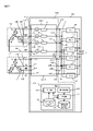
- FIG. 1 It is a schematic block diagram of the power supply system which concerns on Embodiment 1 of this invention. It is a circuit diagram of the power conversion unit which concerns on Embodiment 1.
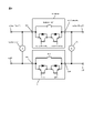
- FIG. It is a circuit diagram of the module main body which concerns on Embodiment 1.
- FIG. It is a figure which shows an example of the information stored in the test case storage part which concerns on Embodiment 1.
- FIG. It is operation explanatory drawing of the switching module which concerns on Embodiment 1.
- FIG. It is an operation explanatory diagram of the switching module which concerns on Embodiment 1, and is the figure which shows the state which determines the presence or absence of the short circuit failure of the bidirectional switch 1A or the bidirectional switch 1D.
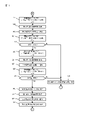
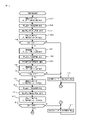
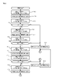
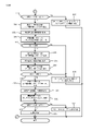
- FIG. It is a flowchart which shows the failure determination process which the control part which concerns on Embodiment 1 performs. It is a flowchart which shows the failure determination process which the control part which concerns on Embodiment 1 performs. It is a flowchart which shows the failure determination process which the control part which concerns on Embodiment 1 performs. It is a flowchart which shows the failure determination process which the control part which concerns on Embodiment 1 performs. It is a flowchart which shows the failure determination process which the control part which concerns on Embodiment 1 performs.
- the switching module according to the present embodiment is used by being connected to, for example, a three-phase four-wire AC power supply having three polar terminals for outputting a phase voltage and a neutral terminal.
- This switching module has one-to-one connection to three first input terminals connected to each of the three polar terminals of the AC power supply, a second input terminal connected to a neutral terminal, and three first input terminals.
- a plurality of first output terminals electrically connected to the second input terminal and a second output terminal electrically connected to the second input terminal are provided.
- the switching module has three first switches connected in series to each of the three first input terminals on a one-to-one basis, and a second switch connected in series between the second input terminal and the second output terminal.
- a switch a first voltmeter that measures the first voltage between the first input terminal and the second input terminal, and a second that measures the second voltage between the first output terminal and the second output terminal. It includes a voltmeter and a control unit that controls each of the three first switches and the second switch. Then, the control unit controls one of the three first switches to the open state, the other two first switches to the closed state, and the second switch to the open state.
- the open state is set.
- a first determination is made to determine that at least one of the controlled first switch and second switch is a short circuit failure. Further, in addition to the first determination, the control unit controls one of the three first switches to the open state and controls the first switch to the open state among the three first switches. With the two first switches and the second switch excluding the switch controlled in the closed state, the first voltage of the first voltmeter connected to the first switch controlled in the open state and the second described above.
- the difference voltage from the voltage is within the voltage range, it is determined that the first switch controlled in the open state has a short-circuit failure, and if it is out of the voltage range, the second switch is determined to have a short-circuit failure. A second determination is also made.
- the power supply system is, for example, a so-called uninterruptible power supply system that supplies power to a server in a data center.
- the power supply system 500 receives AC power supplied from AC power PA1 or standby AC power PB1 to a load such as a server (not shown) connected to the output terminal TeO. Supply DC power.
- the AC power supply PA1 is a Y-connected AC power supply, and has three polar terminals teU, teV, teW and a neutral terminal teN that output phase voltages of U phase, V phase, and W phase.
- the AC power supply PA1 supplies three-phase AC to the power supply system 500 via the four power lines L1A, L1B, L1C, and L1D connected to the polar terminals teU, teV, teW, and the neutral terminal teN, respectively.
- the AC power supply PB1 is also a Y-connected AC power supply, and has three polar terminals teU, teV, teW and a neutral terminal teN.
- the AC power supply PB1 also supplies three-phase AC to the power supply system 500 via the four power lines L2A, L2B, L2C, and L2D connected to the polar terminals teU, teV, teW, and the neutral terminal teN, respectively. Further, circuit breakers BAA, BAB, BAC, BAD, BBA, BBB, BBC, and BBD are inserted in the power lines L1A, L1B, L1C, L1D, L2A, L2B, L2C, and L2D, respectively.
- the power supply system 500 includes six power conversion circuits 201, 202, 203, 204, 205, 206 and a switching module 501.
- the switching module 501 includes two module bodies 100A and 100B, and a control unit 300 that controls their operation.
- the power conversion circuits 201, 202, 203, 204, 205, and 206 each have a rectifying circuit DB, a smoothing capacitor C1 connected between the output ends of the rectifying circuit DB, and a capacitor, respectively, as shown in FIG. 2, for example. It has a DC-DC converter 210 that boosts or lowers the DC voltage generated between both ends of C1 and outputs the DC voltage, and a capacitor C2 for reducing ripple current connected between the output ends of the DC-DC converter 210.
- the DC-DC converter 210 includes, for example, an inductor, a switching element, and a drive circuit for driving the switching element.
- the drive circuit outputs a PWM (Pulse Width Modulation) signal or a PFM (Pulse Frequency Modulation) signal to the switching element based on the command value information indicating the command value of the output voltage input from the control unit 300, thereby DC.
- PWM Pulse Width Modulation
- PFM Pulse Frequency Modulation
- the module main body 100A includes input terminals te1A, te1B, te1C, te1D and output terminals te3A, te3B, te3C, te3D.
- the power lines L1A, L1B, L1C, and L1D connected to the AC power supply PA are connected to the input terminals te1A, te1B, te1C, and te1D, respectively.
- the power supply lines L3A, L3B, L3C, and L3D connected to the power conversion circuits 201, 202, 203, 204, 205, and 206 are connected to the output terminals te3A, te3B, and te3C.
- the module main body 100B also includes input terminals te2A, te2B, te2C, te2D and output terminals te4A, te4B, te4C, te4D.
- Power lines L2A, L2B, L2C, and L2D connected to the standby AC power supply PB are connected to the input terminals te2A, te2B, te2C, and te2D, respectively.
- Power supply lines L4A, L4B, L4C, and L4D connected to the power conversion circuits 201, 202, 203, 204, 205, and 206 are connected to the output terminals te4A, te4B, te4C, and te4D.
- the module main body 100A includes four bidirectional switches 1A, 1B, 1C and 1D, and six voltmeters 12A, 12B, 12C, 13A, 13B and 13C.
- the module main body 100B also has the same configuration as the module main body 100A, and includes four bidirectional switches (not shown) and six voltmeters (not shown).
- the bidirectional switch 1A is connected in series between the input terminal te1A and the output terminal te3A.
- the bidirectional switch 1B is connected in series between the input terminal te1B and the output terminal te3B.
- the bidirectional switch 1C is connected in series between the input terminal te1C and the output terminal te3C.
- the bidirectional switch 1D is connected in series between the input terminal te1D and the output terminal te3D.
- the bidirectional switch 1A (1B, 1C) has one relay ReA (ReB, ReC) and two switching elements Q1A, Q2A (Q1B, Q2B, Q1C, Q2C).
- the bidirectional switch 1D also has one relay ReD and two switching elements Q1D and Q2D.
- the relays ReA, ReB, and ReC are first switches composed of mechanical relays, semiconductor relays, and the like.
- the relay ReD is a second switch having the same configuration as the relays ReA, ReB, and ReC.
- the relay ReA (ReB, ReC) is connected between the input terminal te1A (te1B, te1C) and the output terminal te3A (te3B, te3C).
- the switching elements Q1A and Q2A are, for example, IGBTs (Insulated Gate Bipolar Transistors), and are first switching elements connected in series with each other and connected in parallel with a relay ReA (ReB, ReC). Is. Further, the switching elements Q1D and Q2D are, for example, IGBTs, which are second switching elements connected in series with each other and connected in parallel with the relay Red.
- IGBTs Insulated Gate Bipolar Transistors
- the collector of the switching element Q1A and the anode of the body diode are connected to the input terminal te1A, and the anode of the collector and the body diode of the switching element Q2A are connected to the output terminal te3A.
- the switching elements Q1B and Q2B and the switching elements Q1C and Q2C are also connected to the input terminals te1B and te1C and the output terminals te3B and te3C in the same manner as the switching elements Q1A and Q2A. Further, in the switching elements Q1A and Q2A, their collectors and the cathodes of the body diodes are connected to each other.
- the collector of the switching element Q1A and the anode of the body diode are connected to the input terminal te1A, and the anode of the collector and the body diode of the switching element Q2A are connected to the output terminal te3A.
- their collectors and the cathodes of the body diodes are connected to each other.
- the collector of the switching element Q1D and the anode of the body diode are connected to the input terminal te1D, and the anode of the collector and the body diode of the switching element Q2A are connected to the output terminal te3D.
- the voltmeter 12A is connected between the input ends I1A and I1D of the bidirectional switches 1A and 1D, and the voltmeter 12B is connected between the input ends I1B and I1D of the bidirectional switches 1B and 1D. Further, the voltmeter 12C is connected between the input terminals I1C and I1D of the bidirectional switches 1C and 1D.
- the voltmeter 12A is a first voltmeter that measures the voltage value of the first voltage corresponding to the potential difference between the input terminal te1A and the bidirectional switch 1A and between the input terminal te1D and the bidirectional switch 1D. be.
- the voltmeter 12B is a first voltmeter that measures the voltage value of the first voltage corresponding to the potential difference between the input terminal te1B and the bidirectional switch 1B and between the bidirectional switch 1D of the input terminal te1D. be.
- the voltmeter 12C is a first voltmeter that measures the voltage value of the first voltage corresponding to the potential difference between the input terminal te1C and the bidirectional switch 1C and between the input terminal te1D and the bidirectional switch 1D. be.
- the voltmeters 12A, 12B, and 12C each continuously output a voltage signal reflecting the measured voltage value to the control unit 300.
- the voltmeter 13A is connected between the output ends O1A and O1D of the bidirectional switches 1A and 1D, and the voltmeter 13B is connected between the output ends O1B and O1D of the bidirectional switches 1B and 1D. Further, the voltmeter 13C is connected between the output ends O1C and O1D of the bidirectional switches 1C and 1D.
- the voltmeter 13A is a second voltmeter that measures the voltage value of the second voltage corresponding to the potential difference between the output terminal te3A and the bidirectional switch 1A and between the bidirectional switch 1D of the output terminal te3D. be.
- the voltmeter 13B is a second voltmeter that measures the voltage value of the second voltage corresponding to the potential difference between the output terminal te3B and the bidirectional switch 1B and between the output terminal te3D and the bidirectional switch 1D. be.
- the voltmeter 13C is a second voltmeter that measures the voltage value of the second voltage corresponding to the potential difference between the output terminal te3C and the bidirectional switch 1C and between the output terminal te3D and the bidirectional switch 1D. be.
- the voltmeters 12A, 12B, and 12C each continuously output a voltage signal indicating the measured voltage value to the control unit 300.
- the control unit 300 has, for example, a microcomputer and a memory, and controls the operations of the module main bodies 100A and 100B.
- the control unit 300 has a command unit 301, a voltage acquisition unit 302, a difference calculation unit 303, and a determination unit 304.
- the switching module 501 may be one in which the module main bodies 100A and 100B and the control unit 300 are incorporated in one package, or the module main bodies 100A and 100B and the control unit 300 may be incorporated. May be contained in different packages.
- the module bodies 100A and 100B, the determination unit 304 of the control unit 300, and the memory are incorporated in one package, and the command unit 301 of the control unit 300 is incorporated in another package. There may be.
- the module bodies 100A and 100B, the command unit 301 and the memory of the control unit 300 are incorporated in one package, and the determination unit 304 of the control unit 300 is incorporated in another package. May be.
- the memory is provided with a determination result storage unit 332 for storing determination result information indicating the determination result of presence / absence of failure of the bidirectional switches 1A, 1B, 1C, and 1D by the determination unit 304, and a test case storage unit 331.
- the test case storage unit 331 has the open / closed states of the relays ReA, ReB, ReC, and ReD of the bidirectional switches 1A, 1B, 1C, and 1D, and the switching elements Q1A, Q2A, Q1B, Q2B, and Q1C.
- Q2C, Q1D, and Q2D of eight types of test case information indicating a combination of on / off states are stored in association with the identification information ID [0], ID [1], ..., ID [7].
- the command unit 301 sends an open command signal for opening each of the relays ReA, ReB, ReC, and ReD or a closed command signal for closing the relays to the relays ReA, ReB, ReC, and ReD.
- the open / closed state of the relays ReA, ReB, ReC, and ReD is controlled by outputting each separately.
- the command unit 301 sets the switching element Q1A, Q2A as an on command signal for turning on the switching elements Q1A, Q2A, Q1B, Q2B, Q1C, Q2C, Q1D, and Q2D or an off command signal for turning the switching element Q2A on.
- Q1B, Q2B, Q1C, Q2C, Q1D, and Q2D are output separately to control the on / off states of the switching elements Q1A, Q2A, Q1B, Q2B, Q1C, Q2C, Q1D, and Q2D.
- the command unit 301 when the power supply source to the power supply system 500 is a three-phase AC power supply PA, the command unit 301 outputs a control signal to the module main bodies 100A and 100B, so that the four bidirectional switches 1A of the module main body 100A, The 1B, 1C, and 1D are closed, and the four bidirectional switches (not shown) of the module body 100B are opened.
- the command unit 301 when the power supply source to the power supply system 500 is a standby three-phase AC power supply PB, the command unit 301 outputs control signals to the module main bodies 100A and 100B, thereby causing four directions of the module main body 100A.
- the switches 1A, 1B, 1C, and 1D are opened, and the four bidirectional switches (not shown) of the module body 100B are closed.
- the command unit 301 turns the switching elements Q1A, Q2A, Q1B, Q2B, Q1C, and Q2C on or off by outputting control signals to the gate terminals of the switching elements Q1A, Q2A, Q1B, Q2B, Q1C, and Q2C. do. Further, the command unit 301 relays ReA based on each test case information stored in the test case storage unit 331 each time the voltage acquisition unit 302 notifies the inspection period start command information or the inspection period end command information described later. , ReB, ReC, ReD at least one open / closed state and switching elements Q1A, Q2A, Q1B, Q2B, Q1C, Q2C, Q1D, Q2D at least one on / off state.
- the voltage acquisition unit 302 samples the measurement signals input from the voltmeters 12A, 12B, 12C and the voltmeters 13A, 13B, 13C at a preset sampling cycle, and the sampled measurement signals are the voltage indicating the voltage value. It is converted into value information and notified to the difference calculation unit 303.
- the voltage acquisition unit 302 sends the inspection period start notification information to the command unit 301 and the difference calculation unit 303 based on the voltage information acquired by the voltage acquisition unit 302. Notify to.
- the voltage acquisition unit 302 notifies the start of the inspection period in which the polarity is positive when the polarity of the phase voltage indicated by the acquired voltage information is switched from the negative state to the positive state through the zero cross point. Notify the start notification information.
- the voltage acquisition unit 302 starts the inspection period for notifying the start of the inspection period in which the polarity is negative when the polarity of the phase voltage indicated by the acquired voltage information is switched from the positive state to the negative state through the zero cross point. Notify the notification information.
- the voltage acquisition unit 302 issues inspection period end notification information when a preset inspection period elapses from the time corresponding to the zero crossing point of each phase voltage based on the voltage information acquired by the voltage acquisition unit 302.
- the voltage acquisition unit 302 inspects when the time T1 (T2) corresponding to the zero crossing point of the V-phase voltage arrives based on the voltage information of the V-phase voltage acquired by the voltage acquisition unit 302. Notify the command unit 301 and the difference calculation unit 303 of the period start notification information.
- the voltage acquisition unit 302 notifies the inspection period start notification information notifying the start of the positive inspection period at the time T1, and the inspection period start notification information notifying the start of the negative inspection period at the time T2. Notice.
- the voltage acquisition unit 302 notifies the command unit 301 and the difference calculation unit 303 of the inspection period end notification information when the inspection period dT1 (dT2) has elapsed from the time T1.
- the length of this inspection period dT1 (dT2) is set to a length of 1/2 or less of the setting cycle of the AC output from the three-phase AC power supplies PA and PB, and is set to, for example, 6 msec.
- the command unit 301 opens the relays ReA and ReD when the inspection period start notification information is notified, and opens the relays ReA and ReD when the inspection period end notification information is notified.
- the difference calculation unit 303 has a difference voltage between the voltage value measured by the voltmeter 12A and the voltage value measured by the voltmeter 13A based on the voltage value information notified from the voltage acquisition unit 302. Calculate the absolute value of. Further, the difference calculation unit 302 calculates the absolute value of the difference voltage between the voltage value measured by the voltmeter 12B and the voltage value measured by the voltmeter 13B, and the voltage value and the voltage measured by the voltmeter 12C. The absolute value of the voltage difference from the voltage value measured by the total 13C is calculated.
- the difference calculation unit 303 uses the voltage value information indicating the voltage value measured by the voltage meter 12B and the voltage meter 13B from the voltage acquisition unit 302. Every time the voltage value information indicating the measured voltage value is notified, the absolute value of the difference voltage of the voltage indicated by these voltage value information is calculated. Then, the difference calculation unit 302 notifies the determination unit 304 of the difference voltage information indicating the absolute value of the calculated difference voltage. On the other hand, when the voltage acquisition unit 302 notifies the inspection period end notification information, the difference calculation unit 303 ends the calculation of the absolute value of the difference voltage. As shown in FIG.
- the difference calculation unit 303 uses the V-phase voltage Vin (V-phase) and the voltmeter 13B measured by the voltmeter 12B at the time T1 (T2) when the inspection period start notification information is notified. Calculation of the absolute value of the difference voltage from the measured V-phase voltage Vout (V-phase) and notification of the difference voltage information indicating the calculated absolute value to the determination unit 304 are started. Then, the difference calculation unit 303 ends the calculation of the absolute value of the difference voltage when the inspection period dT1 (dT2) having a length of 1/2 of the cycle of the V-phase AC voltage elapses from the time T1.
- the determination unit 304 determines whether or not the bidirectional switches 1A, 1B, 1C, and 1D have a failure by executing the failure determination process described later.
- the command unit 301 outputs an open command signal to the bidirectional switches 1A and 1D relays ReA and ReD and closes them.
- the command signal is output to the bidirectional switches 1B and 1C relays ReB and ReC.
- the command unit 301 outputs the off command signal to the switching elements Q1A, Q2A, Q1D, and Q2D, and outputs the on command signal to the switching elements Q1B, Q2B, Q1C, and Q2C.
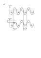
- the relays ReA and ReD of the bidirectional switches 1A and 1D are normal, the relays ReA and ReD are in the open state as shown in FIG. 6A.
- the impedances of the power conversion circuits 201, 202, 203, 204, 205, and 206 viewed from the switching module 1 side are equal to each other, the U phase measured by the voltmeters 13A, 13B, and 13C is shown in FIG. 7A.
- the voltage, V-phase voltage, and W-phase voltage voltage amplitudes Vo_U1, Vo_V1, and Vo_W1 are equal.
- the voltage amplitudes Vi_U, Vi_V, and Vi_W of the U-phase voltage, V-phase voltage, and W-phase voltage measured by the voltmeters 12A, 12B, and 12C are the voltage amplitudes Vo_U1 and Vi_W measured by the voltmeters 13A, 13B, and 13C. Equal to Vo_V1 and Vo_W1.
- the potential of the output terminal te3D changes, so that the V-phase voltage and W
- the voltage amplitudes Vo_V2 and Vo_W2 of the phase voltage are smaller than the voltage amplitudes Vo_V1 and Vo_W1.
- the V-phase voltage and W-phase voltage voltage amplitudes Vi_V and Vi_W measured by the voltmeters 12B and 12C, and the V-phase voltage and W-phase voltage voltage amplitudes Vo_V2 and Vo_W2 measured by the voltmeters 13B and 13C. Will make a difference.
- the determination unit 304 uses this phenomenon to output the open command signal to the relays ReA and ReD of the bidirectional switches 1A and 1D, and outputs the close command signal to the relays ReB and ReC.
- the relays ReA and ReD to which the open command signal is output are normally opened according to the open command signal. It is determined that the relays ReA and ReD are normal.
- the differential voltage threshold value is set to, for example, a magnitude of 10% or less of the voltage effective value of each phase voltage, and is set to about 15V when the voltage effective value of each phase voltage is 200V.
- the determination unit 304 has a state in which the absolute value of the difference voltage is larger than the difference voltage threshold value, that is, a state in which the difference voltage is out of the preset voltage range continues for a preset determination time. It is determined that the relays ReA and ReD are normal. This determination time is set to, for example, 3 msec. Further, the above-mentioned voltage range corresponds to a range of voltage values whose lower limit is a negative voltage value whose absolute value is equal to the differential voltage threshold and whose upper limit is a positive voltage value whose absolute value is equal to the differential voltage threshold. At this time, the voltage value Vin (V phase) of the V phase voltage measured by the voltmeter 13B is, for example, as shown in FIG. 5, the V phase in which the voltage amplitude during the inspection period dT1 (dT2) is measured by the voltmeter 12B. The voltage value of the voltage is smaller than the voltage amplitude of Vout (V phase).
- the determination unit 304 shows the difference voltage information notified from the difference calculation unit 303 in a state where the command unit 301 outputs the open command signal to the relays ReA and ReD and the close command signal is output to the relays ReB and ReC.
- the absolute value of the difference voltage is equal to or less than the above-mentioned difference voltage threshold, that is, when the difference voltage is within the above-mentioned voltage range
- at least one of the relays ReA and ReD to which the open command signal is output is the open command signal. Is maintained in the closed state even though is output, and the first determination is made to determine that at least one of the relays ReA and ReD is a short circuit failure.
- the command unit 301 When the determination unit 304 determines whether or not there is a short-circuit failure in the relays ReB and ReD of the bidirectional switches 1B and 1D, the command unit 301 outputs an open command signal to the relays ReB and ReD and outputs a close command signal to the relay ReA. , Output to ReC. When the determination unit 304 determines whether or not there is a short-circuit failure in the relays ReC and ReD, the command unit 301 outputs an open command signal to the relays ReC and ReD and outputs a close command signal to the relays ReA and ReB.
- the command unit 301 When the determination unit 304 determines whether or not the relay ReA of the bidirectional switch 1A has a short-circuit failure, the command unit 301 outputs an open command signal to the relay ReA of the bidirectional switch 1A and outputs a close command signal to the relay ReB. Output to ReC and ReD. At this time, the command unit 301 outputs the off command signal to the switching elements Q1A and Q2A, and outputs the on command signal to the switching elements Q1B, Q2B, Q1C, Q2C, Q1D and Q2D.
- the relay ReA of the bidirectional switches 1A and 1D is normal, the relay ReA is in the open state as shown in FIG. 6B.
- the determination unit 304 outputs the open command signal to the relay ReA of the bidirectional switch 1A and outputs the close command signal to the relays ReB, ReC, and ReD, and the voltage meter 12A.
- the open command signal When the absolute value of the difference voltage between the voltage amplitude measured by and the voltage amplitude measured by the voltmeter 13A is larger than the above-mentioned difference voltage threshold value, that is, when the difference voltage is outside the above-mentioned voltage range, the open command signal
- the relay ReA of the output destination of the above is normally opened according to the open command signal, and it is determined that the relay ReA is normal.
- the determination unit 304 outputs the open command signal to the relay ReA of the bidirectional switch 1A and the close command signal to the relays ReB, ReC, and ReD, and the voltage measured by the voltmeter 12A.
- the relay to which the open command signal is output is output.
- ReA makes a second determination to determine that the failure is a short circuit that maintains the closed state even though the open command signal is input.
- the command unit 301 outputs an open command signal to the relays ReA, ReB, and ReC to give a close command.
- the signal is output to the relay Red.
- the relays ReA, ReB, and ReC are in the open state, and the relay ReD is in the closed state.
- the command unit 301 outputs the on command signal to all of the switching elements Q1A, Q2A, Q1B, Q2B, Q1C, and Q2C.
- the determination unit 304 when the relays ReA, ReB, and ReC are in the open state and the relay ReD is in the closed state, the absolute value of the difference voltage indicated by the difference voltage information notified from the difference calculation unit 303 exceeds the above-mentioned difference voltage threshold value. That is, when the switching elements Q1A, Q2A, Q1B, Q2B, Q1C, and Q2C whose differential voltage is outside the above-mentioned voltage range are present, the switching elements Q1A, Q2A, Q1B, Q2B, Q1C, and Q2C are on-command signals. Is determined to be an open failure that maintains the off state even though is input.
- the command unit 301 When the determination unit 304 determines whether or not the relays ReA, ReB, and ReC have an open failure, the command unit 301 outputs an off command signal to Q1A, Q2A, Q1B, Q2B, Q1C, and Q2C, and outputs a close command signal. Output to relay RED. As a result, the switching elements Q1A, Q2A, Q1B, Q2B, Q1C, and Q2C are turned off, and the relay Red is closed. At this time, the command unit 301 outputs the closing command signal to all of the relays ReA, ReB, and ReC.
- the determination unit 304 the absolute value of the difference voltage indicated by the difference voltage information notified from the difference calculation unit 303 is obtained when the switching elements Q1A, Q2A, Q1B, Q2B, Q1C, and Q2C are in the off state and the relay Red is in the closed state. If there are relays ReA, ReB, and ReC that exceed the above-mentioned difference voltage threshold, that is, the difference voltage is outside the above-mentioned voltage range, the relays ReA, ReB, and ReC are also input with a close command signal. Regardless, it is determined that the failure is an open failure that maintains the open state.
- the command unit 301 when the determination unit 304 determines whether or not the switching elements Q1D and Q2D have an open failure, the command unit 301 outputs an open command signal to the relays ReA and ReD, and outputs an off command signal to the Q1A and Q2A. Further, the command unit 301 outputs an on command signal to Q1D and Q2D.
- the switching elements Q1B, Q2B, Q1C, and Q2C are in the ON state, and the switching elements Q1A, Q2A are in the OFF state.
- the relays ReB and ReC are closed.
- the determination unit 304 determines that the absolute value of the difference voltage indicated by the difference voltage information of the V phase or the W phase notified from the difference calculation unit 303 exceeds the above-mentioned difference voltage threshold value, that is, the difference voltage is When it is out of the voltage range described above, it is determined that the switching elements Q1D and Q2D are open failures that maintain the off state even though the on command signal is input.
- the command unit 301 When the determination unit 304 determines whether or not the relay Red has an open failure, the command unit 301 outputs an open command signal to the relay ReA and outputs an off command signal to Q1A, Q2A, Q1D, and Q2D. Further, the command unit 301 outputs a close command signal to the relay Red.
- the switching elements Q1B, Q2B, Q1C, and Q2C are in the ON state, and the relays ReB and ReC are in the closed state. Then, in this state, when the absolute value of the difference voltage indicated by the difference voltage information notified from the difference calculation unit 303 exceeds the above-mentioned difference voltage threshold value, the relay Red is input with the closing command signal. It is determined that the failure is an open failure that maintains the open state in spite of the presence.
- the determination unit 304 stores information indicating the determination result in the determination result storage unit 332.
- the failure determination process executed by the determination unit 304 according to the present embodiment will be described with reference to FIGS. 9 to 13.
- the bidirectional switches 1A, 1B, 1C, and 1D relays ReA, ReB, ReC, and ReD are all closed, and the switching elements Q1A, Q2A, Q1B, Q2B, Q1C, and Q2C. , Q1D and Q2D are all in the ON state.
- the command unit 301 stores the identification information IDT [0] stored in the test case storage unit 331.
- the open command signal is output to the relay ReA, and the off command signal is output to the switching elements Q1A and Q2A (step S1).
- the command unit 301 keeps the relays ReB, ReC, and ReD in the closed state, and keeps the switching elements Q1B, Q2B, Q1C, Q2C, Q1D, and Q2D in the on state.
- the voltage acquisition unit 302 acquires the voltage value measured by the voltmeter 12A and the voltage value measured by the voltmeter 13A during the inspection period in which the polarity is positive (step S2).
- "acquiring the voltage value” means converting the measurement signal input from the voltmeters 12A and 13A into the voltage value information. The same applies hereinafter.
- the difference calculation unit 303 calculates the absolute value of the difference voltage between the voltage value measured by the voltmeter 12A and the voltage value measured by the voltmeter 13A, and determines the absolute value of the calculated difference voltage 304. (Step S3). After that, when the voltage acquisition unit 302 notifies the inspection period end notification information, the command unit 301 outputs the close command signal to the relay ReA and outputs the on command signal to the switching elements Q1A and Q2A (step S4). .. Next, the determination unit 304 determines whether or not the absolute value
- step S5 determines that the absolute value
- step S6 determines that the bidirectional switch 1A has a short-circuit failure
- the determination unit 304 determines that the absolute value
- the command unit 301 outputs the open command signal to the relay ReA again and outputs the off command signal to the switching element Q1A. , Output to Q2A (step S7).
- the command unit 301 keeps the relays ReB, ReC, and ReD in the closed state, and keeps the switching elements Q1B, Q2B, Q1C, Q2C, Q1D, and Q2D in the on state.
- the voltage acquisition unit 302 acquires the voltage value measured by the voltmeter 12A and the voltage value measured by the voltmeter 13A during the inspection period in which the polarity is negative (step S8).
- the difference calculation unit 303 calculates the absolute value of the difference voltage between the voltage value measured by the voltmeter 12A and the voltage value measured by the voltmeter 13A, and determines the absolute value of the calculated difference voltage in the determination unit 304. Notify (step S9).
- the command unit 301 outputs a close command signal to the relay ReA and outputs an on command signal to the switching elements Q1A and Q2A (step S10). ).
- the determination unit 304 determines whether or not the absolute value
- the determination unit 304 determines that the absolute value
- the determination unit 304 determines that the absolute value
- the command unit 301 corresponds to the identification information IDT [1] stored in the test case storage unit 331.
- the open command signal is output to the relay ReB, and the off command signal is output to the switching elements Q1B and Q2B (step S12).
- the command unit 301 keeps the relays ReA, ReC, and ReD in the closed state, and keeps the switching elements Q1A, Q2A, Q1C, Q2C, Q1D, and Q2D in the on state.
- the voltage acquisition unit 302 acquires the voltage value measured by the voltmeter 12B and the voltage value measured by the voltmeter 13B during the inspection period in which the polarity is positive (step S13).
- the difference calculation unit 303 calculates the absolute value of the difference voltage between the voltage value measured by the voltmeter 12B and the voltage value measured by the voltmeter 13B, and determines the absolute value of the calculated difference voltage 304. (Step S14).
- the command unit 301 outputs the close command signal to the relay ReB and outputs the on command signal to the switching elements Q1B and Q2B (step S15). ).
- the determination unit 304 determines whether or not the absolute value
- step S16 determines that the absolute value
- step S17 it is determined that the bidirectional switch 1B has a short-circuit failure (step). S17), the failure determination process is completed.
- the determination unit 304 determines that the absolute value
- the command unit 301 outputs the open command signal to the relay ReB again and outputs the open command signal to the relay ReB.
- the off command signal is output to the switching elements Q1B and Q2B (step S18).
- the voltage acquisition unit 302 acquires the voltage value measured by the voltmeter 12B and the voltage value measured by the voltmeter 13B during the inspection period in which the polarity is negative (step S19).
- the difference calculation unit 303 calculates the absolute value of the difference voltage between the voltage value measured by the voltmeter 12B and the voltage value measured by the voltmeter 13B, and determines the absolute value of the calculated difference voltage 304. (Step S20). After that, when the voltage acquisition unit 302 notifies the inspection period end notification information, the command unit 301 outputs the close command signal to the relay ReB and outputs the on command signal to the switching elements Q1B and Q2B (step S21). ..
- the determination unit 304 determines whether or not the absolute value
- the determination unit 304 determines that the absolute value
- the bidirectional switch 1B has a short-circuit failure as shown in FIG. (Step S17), and the failure determination process ends.
- the determination unit 304 determines that the absolute value
- the command unit 301 corresponds to the identification information IDT [2] stored in the test case storage unit 331.
- the open command signal is output to the relay ReC, and the off command signal is output to the switching elements Q1C and Q2C (step S23).
- the command unit 301 keeps the relays ReA, ReB, and ReD in the closed state, and keeps the switching elements Q1A, Q2A, Q1B, Q2B, Q1D, and Q2D in the on state.
- the voltage acquisition unit 302 acquires the voltage value measured by the voltmeter 12C and the voltage value measured by the voltmeter 13C during the inspection period in which the polarity is positive (step S24).
- the difference calculation unit 303 calculates the absolute value of the difference voltage between the voltage value measured by the voltmeter 12C and the voltage value measured by the voltmeter 13C, and determines the absolute value of the calculated difference voltage 304. (Step S25).
- the command unit 301 outputs the close command signal to the relay ReC and outputs the on command signal to the switching elements Q1C and Q2C (step S26). ).
- the determination unit 304 determines whether or not the absolute value
- step S27 determines that the absolute value
- step S28 it is determined that the bidirectional switch 1C has a short-circuit failure (step). S28), the failure determination process is completed.
- the determination unit 304 determines that the absolute value
- the command unit 301 outputs the open command signal to the relay ReC again and outputs the off command signal to the switching element Q1C. , Output to Q2C (step S29).
- the voltage acquisition unit 302 acquires the voltage value measured by the voltmeter 12C and the voltage value measured by the voltmeter 13C during the inspection period in which the polarity is negative (step S30).
- the difference calculation unit 303 calculates the absolute value of the difference voltage between the voltage value measured by the voltmeter 12C and the voltage value measured by the voltmeter 13C, and determines the absolute value of the calculated difference voltage 304. (Step S31). After that, when the voltage acquisition unit 302 notifies the inspection period end notification information, the command unit 301 outputs the close command signal to the relay ReC and outputs the on command signal to the switching elements Q1C and Q2C (step S32). ..
- the determination unit 304 determines whether or not the absolute value
- the determination unit 304 determines that the absolute value
- the failure determination process is completed.
- the determination unit 304 determines that the absolute value
- the command unit 301 stores the identification information IDT [ With reference to the test case information corresponding to 3], the open command signal is output to the relays ReA and ReD, and the off command signal is output to the switching elements Q1A, Q2A, Q1D and Q2D (step S34).
- the command unit 301 keeps the relays ReB and ReC in the closed state, and keeps the switching elements Q1B, Q2B, Q1C, and Q2C in the on state.
- the voltage acquisition unit 302 acquires the voltage value measured by the voltmeter 12B and the voltage value measured by the voltmeter 13B during the inspection period in which the polarity is positive (step S35).
- the difference calculation unit 303 calculates the absolute value of the difference voltage between the voltage value measured by the voltmeter 12B and the voltage value measured by the voltmeter 13B, and determines the absolute value of the calculated difference voltage 304. (Step S36).
- the command unit 301 outputs a close command signal to the relays ReA and ReD, and outputs an on command signal to the switching elements Q1A, Q2A, Q1D, and Q2D. Output to (step S37).
- the determination unit 304 determines whether or not the absolute value
- step S38 determines that the absolute value
- step S39 it is determined that the bidirectional switch 1D has a short-circuit failure (step). S39), the failure determination process is completed.
- the determination unit 304 determines that the absolute value
- the command unit 301 outputs the open command signal to the relays ReA and ReD again and switches the off command signal. Output to the elements Q1A, Q2A, Q1D, and Q2D (step S40).
- the voltage acquisition unit 302 acquires the voltage value measured by the voltmeter 12B and the voltage value measured by the voltmeter 13B during the inspection period in which the polarity is negative (step S41).
- the difference calculation unit 303 calculates the absolute value of the difference voltage between the voltage value measured by the voltmeter 12B and the voltage value measured by the voltmeter 13B, and determines the absolute value of the calculated difference voltage 304. (Step S42). After that, when the voltage acquisition unit 302 notifies the inspection period end notification information, the command unit 301 outputs a close command signal to the relays ReA and ReD, and outputs an on command signal to the switching elements Q1A, Q2A, Q1D, and Q2D. Output (step S43).
- the determination unit 304 determines whether or not the absolute value
- the determination unit 304 determines that the absolute value
- the failure determination process is completed.
- the determination unit 304 determines that the absolute value
- the command unit 301 is a test case corresponding to the identification information IDT [4] stored in the test case storage unit 331.
- the open command signal is output to the relays ReA, ReB, and ReC (step S45).
- the command unit 301 keeps the relay ReD in the closed state and keeps the switching elements Q1A, Q2A, Q1B, Q2B, Q1C, Q2C, Q1D, and Q2D in the on state.
- the voltage acquisition unit 302 acquires the voltage value measured by each of the voltmeters 12A, 12B, 12C and the voltage value measured by each of the voltmeters 13A, 13B, 13C during the inspection period in which the polarity is positive (step). S46).
- the difference calculation unit 303 calculates the absolute value of the difference voltage between the voltage values measured by the voltmeters 12A, 12B, and 12C and the voltage values measured by the corresponding voltmeters 13A, 13B, and 13C.
- step S47 Notify the determination unit 304 of the absolute value of the calculated difference voltage (step S47). Subsequently, when the voltage acquisition unit 302 notifies the inspection period end notification information, the command unit 301 outputs a close command signal to the relays ReA, ReB, and ReC (step S48). After that, as shown in FIG. 12, the determination unit 304 has a phase in which the absolute value
- the determination unit 304 determines that there is a phase in which the absolute value
- the determination unit 304 determines that the absolute value
- the command unit 301 corresponds to the identification information IDT [5] stored in the test case storage unit 331.
- the open command signal is output to the relays ReA, ReB, and ReC (step S51).
- the command unit 301 outputs the on command signal to the switching elements Q1A, Q2A, Q1B, Q2B, Q1C, and Q2C.
- the command unit 301 keeps the relay ReD in the closed state and keeps the switching elements Q1A, Q2A, Q1B, Q2B, Q1C, Q2C, Q1D, and Q2D in the on state.
- the voltage acquisition unit 302 acquires the voltage value measured by each of the voltmeters 12A, 12B, 12C and the voltage value measured by each of the voltmeters 13A, 13B, 13C during the inspection period in which the polarity is negative ( Step S52).
- the difference calculation unit 303 calculates the absolute value of the difference voltage between the voltage values measured by the voltmeters 12A, 12B, and 12C and the voltage values measured by the corresponding voltmeters 13A, 13B, and 13C.
- Step S53 Notify the determination unit 304 of the absolute value of the calculated difference voltage (step S53).
- the command unit 301 outputs a close command signal to the relays ReA, ReB, and ReC (step S54).
- the determination unit 304 determines whether or not there is a phase in which the absolute value
- the determination unit 304 determines that there is a phase in which the absolute value
- the determination unit 304 determines that the absolute value
- the command unit 301 stores the identification information IDT [6] stored in the test case storage unit 331.
- the off command signal is output to the switching elements Q1A, Q2A, Q1B, Q2B, Q1C, and Q2C with reference to the test case information corresponding to (step S56).
- the command unit 301 outputs the closing command signal to the relays ReA, ReB, and ReC.
- the command unit 301 keeps the relay ReD in the closed state and keeps the switching elements Q1D and Q2D in the on state.
- the voltage acquisition unit 302 sets the voltage value measured by each of the voltmeters 12A, 12B, 12C and the voltage value measured by each of the voltmeters 13A, 13B, 13C during the inspection period in which the polarity is positive or the inspection period in which the polarity is negative. (Step S57).
- the difference calculation unit 303 calculates the absolute value of the difference voltage between the voltage values measured by the voltmeters 12A, 12B, and 12C and the voltage values measured by the corresponding voltmeters 13A, 13B, and 13C.
- Step S58 Notify the determination unit 304 of the calculated absolute value of the difference voltage (step S58).
- the command unit 301 outputs an on command signal to the switching elements Q1A, Q2A, Q1B, Q2B, Q1C, and Q2C (step S59).
- the determination unit 304 determines whether or not there is a phase in which the absolute value
- the determination unit 304 determines that there is a phase in which the absolute value
- is an open failure. It is determined that there is (step S61), and the failure determination process ends.
- the determination unit 304 determines that the absolute value
- the command unit 301 corresponds to the identification information IDT [7] stored in the test case storage unit 331.
- the open command signal is output to the relays ReA and ReD, and the off command signal is output to the switching elements Q1A and Q2A (step S62).
- the command unit 301 outputs the on command signal to the switching elements Q1D and Q2D.
- the command unit 301 keeps the relays ReB and ReC in the closed state and keeps the switching elements Q1B, Q2B, Q1C and Q2C in the on state.
- the voltage acquisition unit 302 acquires the voltage value measured by the voltmeter 12B and the voltage value measured by the voltmeter 13B during the inspection period in which the polarity is negative (step S63).
- the difference calculation unit 303 calculates the absolute value of the difference voltage between the voltage value measured by the voltmeter 12B and the voltage value measured by the voltmeter 13B, and determines the absolute value of the calculated difference voltage 304. (Step S64).
- the command unit 301 outputs the close command signal to the relays ReA and ReD, and outputs the on command signal to the switching elements Q1A and Q2A (step). S65).
- the determination unit 304 determines whether or not the absolute value
- step S66 determines that the absolute value
- step S67 determines that the switching element Q2D has an open failure (step S67).
- the failure determination process ends.
- step S66 determines that the absolute value
- the command unit 301 outputs the open command signal to the relays ReA and ReD again and switches the off command signal. Output to the elements Q1A and Q2A (step S68).
- the command unit 301 outputs the on command signal to the switching elements Q1D and Q2D.
- the command unit 301 keeps the relays ReB and ReC in the closed state and keeps the switching elements Q1B, Q2B, Q1C and Q2C in the on state.
- the voltage acquisition unit 302 acquires the voltage value measured by the voltmeter 12B and the voltage value measured by the voltmeter 13B during the inspection period in which the polarity is negative (step S69).
- the difference calculation unit 303 calculates the absolute value of the difference voltage between the voltage value measured by the voltmeter 12B and the voltage value measured by the voltmeter 13B, and the calculated absolute value of the difference voltage is used in the determination unit 304. Notify (step S70).
- the command unit 301 outputs the close command signal to the relays ReA and ReD, and outputs the on command signal to the switching elements Q1A and Q2A (Ste S71).
- the determination unit 304 determines whether or not the absolute value
- step S72 determines that the absolute value
- step S67 determines that the switching element Q1D has an open failure (step S67).
- the failure determination process ends.
- the determination unit 304 determines that the absolute value
- the command unit 301 outputs an open command signal to the relay ReA and also outputs an off command signal. Is output to the switching elements Q1A, Q2A, Q1D, and Q2D (step S73).
- the command unit 301 outputs the closing command signal to the relay ReD.
- the command unit 301 keeps the relays ReB and ReC in the closed state and keeps the switching elements Q1B, Q2B, Q1C and Q2C in the on state.
- the voltage acquisition unit 302 acquires the voltage value measured by the voltmeter 12B and the voltage value measured by the voltmeter 13B during the inspection period in which the polarity is positive or the inspection period in which the polarity is negative (step S74).
- the difference calculation unit 303 calculates the absolute value of the difference voltage between the voltage value measured by the voltmeter 12B and the voltage value measured by the voltmeter 13B, and determines the absolute value of the calculated difference voltage 304. (Step S75).
- the command unit 301 outputs a close command signal to the relay ReA and outputs an on command signal to the switching elements Q1A, Q2A, Q1D, and Q2D. (Step S76). Subsequently, the determination unit 304 determines whether or not the absolute value
- step S77 when the determination unit 304 determines that the absolute value
- the impedance of the power conversion circuits 201 and 204 connected to the U-phase output terminals te3A is the impedance of the power conversion circuits 202, 203, 205 and 206 connected to the V and W-phase output terminals te3B and te3C. Is larger than. In this case, as shown in FIG.
- the voltage amplitude Vo_U3 of the voltage measured by the voltmeter 13A is larger than the voltage amplitudes Vo_V3 and Vo_W3 of the voltage measured by the voltmeters 13B and 13C. Therefore, it is possible to determine the presence or absence of failure of the bidirectional switch 1D based on the absolute value of the voltage measured by the voltmeters 12A, 12B, 12C and the difference voltage measured by the voltmeters 13A, 13B, 13C.
- the voltmeters 13A, 13B, and 13C are equal to each other, the voltmeters 13A, 13B, and 13C, respectively.
- the voltage amplitudes Vo_U3, Vo_V3, and Vo_W3 of the measured voltage are equal to each other, and are equal to the voltage amplitudes Vo_U1, Vo_V1, and Vo_W1 of the voltages measured by the above-mentioned voltmeters 12A, 12B, and 12C, respectively. Therefore, since the absolute value of the above-mentioned difference voltage does not change regardless of the open / closed state of the bidirectional switch 1D, it is not possible to determine whether or not the bidirectional switch 1D has failed.
- the command unit 301 outputs the open command signal to the relays ReA and ReD, and outputs the close command signal to the relays ReB and ReC.
- the determination unit 304 at least one of the relays ReA and ReD. It is determined that one is a short circuit failure.
- the determination unit 304 measures with the voltage meters 12A and 13A in a state where the command unit 301 outputs the open command signal to the relay ReA and the close command signal is output to the relays ReB, ReC and ReD.
- the absolute value of the difference voltage of the voltage value to be performed is equal to or less than the above-mentioned difference voltage threshold value, it is determined that the relay ReA has a short circuit failure.
- the determination unit 304 determines whether or not the relays ReB and ReC have a short-circuit failure in the same manner for the relays ReB and ReC. This makes it possible to identify the presence or absence of a short-circuit failure of the relays ReA, ReB, and ReC.
- the command unit 301 sends an ON command signal to the switching elements Q1A, Q2A, Q1B, Q2B, Q1C, Q2C, and Q1D. If the absolute value of the above-mentioned difference voltage exceeds the above-mentioned difference voltage threshold value in the state of being output to Q2D, it is determined that it is an open failure. Thereby, the open failure of the switching elements Q1A, Q2A, Q1B, Q2B, Q1C, and Q2C can be discriminated.
- the command unit 301 when the switching elements Q1A, Q2A, Q1B, Q2B, Q1C, and Q2C are in the ON state, the command unit 301 outputs a close command signal to the relays ReA, ReB, and ReC. If the absolute value of the above-mentioned difference voltage exceeds the above-mentioned difference voltage threshold value in the above-mentioned state, it is determined that it is an open failure. This makes it possible to determine an open failure of the relays ReA, ReB, and ReC.
- the command unit 301 sends an on-command signal to the switching elements Q1D and Q2D.
- the absolute value of the above-mentioned difference voltage exceeds the above-mentioned difference voltage threshold value for the switching elements Q1D and Q2D in the output state, it is determined that the switching elements Q1D and Q2D are open failures. Thereby, the open failure of the switching elements Q1D and Q2D can be discriminated.
- the power supply lines L1D and L2D of the module main body 100A and 100B are connected to a common ground wire, respectively.
- the bidirectional switch 1D fails due to a short circuit
- the bidirectional switches 1A, 1B, and 1C are opened, the bidirectional switch of the module body 100B is closed without stopping the output of the AC power supply PA1. You may do it.
- any of the bidirectional switches 1A, 1B, and 1C is short-circuited, if the bidirectional switch of the module main body 100B is closed without stopping the output of the AC power supply PA1, the wiring of the module main body 100B is short-circuited.
- the switching module 501 may be any of the switching elements Q1A, Q2A, Q1B, Q2B, Q1C, Q2C, Q1D, and Q2D by executing the above-mentioned series of failure determination processes. Since it is possible to determine whether or not an open failure has occurred, it is possible to appropriately determine whether or not the module bodies 100A and 100B can be used continuously.
- the switching module according to the present embodiment is different from the first embodiment in that it is used by being connected to a single-phase three-wire AC power supply having two polar terminals for outputting a phase voltage and a neutral terminal. ..
- the power supply system 2500 is a server (not shown) connected to the output terminal TeO by receiving AC power supply from the AC power supply PA2 or the standby AC power supply PB2.
- Supply DC power to loads such as.
- the AC power supply PA2 has two polar terminals teH and teL and a neutral terminal teN.
- the AC power supply PA2 supplies AC to the power supply system 2500 via three power lines L1A, L1B, and L1D connected to the polar terminals teH, teL, and the neutral terminal teN, respectively.
- the AC power supply PB also has two polar terminals teH and teL and a neutral terminal teN.
- the AC power supply PB also supplies AC to the power supply system 2500 via the three power lines L2A, L2B, and L2D connected to the polar terminals teH, teL, and the neutral terminal teN, respectively.
- circuit breakers BAA, BAB, BAD, BBA, BBB, and BBD are inserted in the power lines L1A, L1B, L1D, L2A, L2B, and L2D, respectively.
- the power supply system 2500 includes four power conversion circuits 201, 202, 203, 204 and a switching module 501.
- the switching module 501 includes two module main bodies 2100A and 2100B, and a control unit 2300 for controlling their operation.
- the module main body 2100A includes input terminals te1A, te1B, te1D and output terminals te3A, te3B, te3D.
- the power lines L1A, L1B, and L1D connected to the AC power supply PA2 are connected to the input terminals te1A, te1B, and te1D, respectively.
- the power supply lines L3A, L3B, and L3D connected to the power conversion circuits 201, 202, 203, and 204 are connected to the output terminals te3A, te3B, and te3D.
- the module main body 2100B also includes input terminals te2A, te2B, te2D and output terminals te4A, te4B, te4D.
- Power lines L2A, L2B, and L2D connected to the standby AC power supply PB2 are connected to the input terminals te2A, te2B, and te2D, respectively.
- Power lines L4A, L4B, and L4D connected to the power conversion circuits 201, 202, 203, and 204 are connected to the output terminals te4A, te4B, and te4D.
- the module main body 2100A includes three bidirectional switches 1A, 1B and 1D, and four voltmeters 12A, 12B, 13A and 13B.
- the module main body 2100B also has the same configuration as the module main body 100A, and includes three bidirectional switches (not shown) and four voltmeters (not shown).
- the bidirectional switch 1A (1B) has one relay ReA (ReB) and two switching elements Q1A and Q2A (Q1B, Q2B) as described with reference to FIG. 3 in the first embodiment. Further, the bidirectional switch 1D also has one relay ReD and two switching elements Q1D and Q2D.
- the voltmeter 12A is connected between the input ends I1A and I1D of the bidirectional switches 1A and 1D, and the voltmeter 12B is connected between the input ends I1B and I1D of the bidirectional switches 1B and 1D.
- the voltmeter 13A is connected between the output ends O1A and O1D of the bidirectional switches 1A and 1D, and the voltmeter 13B is connected between the output ends O1B and O1D of the bidirectional switches 1B and 1D.
- the control unit 2300 has the same hardware configuration as the control unit 300 of the first embodiment, and controls the operation of the module main bodies 2100A and 2100B.
- the control unit 2300 has a command unit 2301, a voltage acquisition unit 302, a difference calculation unit 303, and a determination unit 2304.
- the memory is provided with a determination result storage unit 332 and a test case storage unit 2331.
- the test case storage unit 2331 turns on / off the relays ReA, ReB, and ReD of the bidirectional switches 1A, 1B, and 1D, and the switching elements Q1A, Q2A, Q1B, Q2B, Q1D, and Q2D. Seven test case information indicating a combination of states is stored in association with the identification information IDT [10], IDT [11], ..., IDT [16].
- the command unit 2301 outputs the open command signal for opening each of the relays ReA, ReB, and ReD or the closed command signal for closing the relays to the relays ReA, ReB, and ReD separately, thereby relaying ReA and ReB. , Controls the open / closed state of the relay. Further, the command unit 2301 sets an on command signal for turning on the switching elements Q1A, Q2A, Q1B, Q2B, Q1D, and Q2D or an off command signal for turning off the switching elements Q1A, Q2A, Q1B, and Q2B. , Q1D and Q2D are output separately to control the on / off states of the switching elements Q1A, Q2A, Q1B, Q2B, Q1D and Q2D.
- the determination unit 2304 determines whether or not the bidirectional switches 1A, 1B, and 1D have a failure by executing the failure determination process described later.
- the command unit 2301 outputs an open command signal to the relays ReA and ReD of the bidirectional switches 1A and 1D and closes them.
- the command signal is output to the bidirectional switches 1B and 1C relays ReB and ReC.
- the command unit 2301 outputs the off command signal to the switching elements Q1A, Q2A, Q1D, and Q2D, and outputs the on command signal to the switching elements Q1B, Q2B.
- the determination unit 2304 is notified from the difference calculation unit 303 in a state where the command unit 2301 outputs the open command signal to the relays ReA and ReD of the bidirectional switches 1A and 1D and outputs the close command signal to the relays ReB and ReC.
- the determination unit 2304 is in a state where the command unit 2301 outputs the open command signal to the relays ReA and ReD and outputs the close command signal to the relays ReB and ReC, and the absolute value of the difference voltage is equal to or less than the difference voltage threshold value.
- the command unit 2301 outputs an open command signal to the relays ReB and ReD and outputs a close command signal to the relay ReA. , Output to ReC.
- the command unit 2301 When the determination unit 2304 determines whether or not the relay ReA of the bidirectional switch 1A has a short-circuit failure, the command unit 2301 outputs an open command signal to the relay ReA of the bidirectional switch 1A and outputs a close command signal to the relay ReB. Output to Red. At this time, the command unit 2301 outputs the off command signal to the switching elements Q1A and Q2A, and outputs the on command signal to the switching elements Q1B, Q2B, Q1D and Q2D.
- the determination unit 2304 is a voltage amplitude and voltmeter measured by the voltmeter 12A in a state where the command unit 2301 outputs the open command signal to the relay ReA of the bidirectional switch 1A and outputs the close command signal to the relays ReB and ReD.
- the determination unit 2304 determines that the relay ReA is normal.
- the absolute value of the above-mentioned difference voltage is obtained in a state where the command unit 2301 outputs the open command signal to the relay ReA of the bidirectional switch 1A and outputs the close command signal to the relays ReB, ReC, and ReD. If it is equal to or less than the preset differential voltage threshold, it is determined that the relay ReA has a short circuit failure.
- the command unit 2301 when the determination unit 2304 determines whether or not the switching elements Q1A, Q2A, Q1B, and Q2B have an open failure, the command unit 2301 outputs an open command signal to the relays ReA and ReB, and outputs a close command signal to the relay Red. do. At this time, the command unit 2301 outputs the on command signal to all of the switching elements Q1A, Q2A, Q1B, and Q2B. Then, the determination unit 2304 is a switching element in which the absolute value of the difference voltage indicated by the difference voltage information notified from the difference calculation unit 303 exceeds the above-mentioned difference voltage threshold value when the relays ReA and ReB are in the open state and the relay ReD is in the closed state. When Q1A, Q2A, Q1B, and Q2B are present, it is determined that the switching elements Q1A, Q2A, Q1B, and Q2B are open failures.
- the command unit 2301 When the determination unit 2304 determines whether or not the relays ReA and ReB have an open failure, the command unit 2301 outputs an off command signal to Q1A, Q2A, Q1B, and Q2B, and outputs a close command signal to the relay Red. As a result, the switching elements Q1A, Q2A, Q1B, and Q2B are turned off, and the relay Red is closed. At this time, the command unit 2301 outputs the closing command signal to all of the relays ReA and ReB.
- the determination unit 2304 when the switching elements Q1A, Q2A, Q1B, and Q2B are in the off state and the relay Red is in the closed state, the absolute value of the difference voltage indicated by the difference voltage information notified from the difference calculation unit 303 is the above-mentioned difference voltage. If there are relays ReA and ReB that exceed the threshold value, it is determined that the relays ReA and ReB are open failures.
- the command unit 2301 when the determination unit 2304 determines whether or not the switching elements Q1D and Q2D have an open failure, the command unit 2301 outputs an open command signal to the relays ReA and ReD, and outputs an off command signal to the Q1A and Q2A. Further, the command unit 2301 outputs an on command signal to Q1D and Q2D.
- the switching elements Q1A, Q2A, Q1B, and Q2B are in the ON state, and the relay ReB is in the closed state.
- the determination unit 2304 determines that the switching elements Q1D and Q1D are open failures. judge.
- the command unit 2301 When the determination unit 2304 determines whether or not the relay Red has an open failure, the command unit 2301 outputs an open command signal to the relay ReA and outputs an off command signal to Q1A, Q2A, Q1D, and Q2D. Further, the command unit 2301 outputs a close command signal to the relay ReD.
- the switching elements Q1B and Q2B are in the ON state, and the relay ReB is in the closed state. Then, in this state, when the absolute value of the difference voltage indicated by the difference voltage information notified from the difference calculation unit 303 exceeds the above-mentioned difference voltage threshold value, the determination unit 2304 determines that the relay Red is an open failure.
- the determination unit 2304 stores information indicating the determination result in the determination result storage unit 332.
- the failure determination process executed by the determination unit 2304 according to the present embodiment will be described with reference to FIGS. 17 to 20.
- the bidirectional switches 1A, 1B, and 1D relays ReA, ReB, and ReD are all closed, and the switching elements Q1A, Q2A, Q1B, Q2B, Q1D, and Q2D are all on.
- the command unit 2301 stores the identification information IDT [10] stored in the test case storage unit 2331.
- the open command signal is output to the relay ReA, and the off command signal is output to the switching elements Q1A and Q2A (step S201).
- the command unit 2301 keeps the relays ReB and ReD in the closed state, and keeps the switching elements Q1B, Q2B, Q1D, and Q2D in the on state.
- the voltage acquisition unit 302 acquires the voltage value measured by the voltmeter 12A and the voltage value measured by the voltmeter 13A during the inspection period in which the polarity is positive (step S202).
- the difference calculation unit 303 calculates the absolute value of the difference voltage between the voltage value measured by the voltmeter 12A and the voltage value measured by the voltmeter 13A, and determines the absolute value of the calculated difference voltage in the determination unit 2304. (Step S203). After that, when the voltage acquisition unit 302 notifies the inspection period end notification information, the command unit 2301 outputs a close command signal to the relay ReA and outputs an on command signal to the switching elements Q1A and Q2A (step S204). .. Next, the determination unit 2304 determines whether or not the absolute value
- step S205 when the determination unit 2304 determines that the absolute value
- the determination unit 2304 determines that the absolute value
- the command unit 2301 outputs the open command signal to the relay ReA again and outputs the off command signal to the switching element Q1A. , Output to Q2A (step S207).
- the command unit 2301 keeps the relays ReB and ReD in the closed state, and keeps the switching elements Q1B, Q2B, Q1D, and Q2D in the on state.
- the voltage acquisition unit 302 acquires the voltage value measured by the voltmeter 12A and the voltage value measured by the voltmeter 13A during the inspection period in which the polarity is negative (step S208).
- the difference calculation unit 303 calculates the absolute value of the difference voltage between the voltage value measured by the voltmeter 12A and the voltage value measured by the voltmeter 13A, and determines the absolute value of the calculated difference voltage in the determination unit 2304. Notify (step S209).
- the command unit 2301 outputs a close command signal to the relay ReA and outputs an on command signal to the switching elements Q1A and Q2A (step S210). ).
- the determination unit 2304 determines whether or not the absolute value
- the determination unit 2304 determines that the absolute value
- the failure determination process is completed.
- the determination unit 2304 determines that the absolute value
- the command unit 2301 corresponds to the identification information IDT [11] stored in the test case storage unit 331.
- the open command signal is output to the relay ReB, and the off command signal is output to the switching elements Q1B and Q2B (step S212).
- the command unit 2301 keeps the relays ReA and ReD in the closed state, and keeps the switching elements Q1A, Q2A, Q1D, and Q2D in the on state.
- the voltage acquisition unit 302 acquires the voltage value measured by the voltmeter 12B and the voltage value measured by the voltmeter 13B during the inspection period in which the polarity is positive (step S213).
- the difference calculation unit 303 calculates the absolute value of the difference voltage between the voltage value measured by the voltmeter 12B and the voltage value measured by the voltmeter 13B, and determines the absolute value of the calculated difference voltage in the determination unit 2304. (Step S214).
- the command unit 2301 outputs a close command signal to the relay ReB and outputs an on command signal to the switching elements Q1B and Q2B (step S215).
- the determination unit 2304 determines whether or not the absolute value
- the determination unit 2304 determines that the absolute value
- the determination unit 2304 determines that the absolute value
- the command unit 2301 outputs the open command signal to the relay ReB again and outputs the open command signal to the relay ReB.
- the off command signal is output to the switching elements Q1B and Q2B (step S218).
- the voltage acquisition unit 302 acquires the voltage value measured by the voltmeter 12B and the voltage value measured by the voltmeter 13B during the inspection period in which the polarity is negative (step S219).
- the difference calculation unit 303 calculates the absolute value of the difference voltage between the voltage value measured by the voltmeter 12B and the voltage value measured by the voltmeter 13B, and determines the absolute value of the calculated difference voltage in the determination unit 2304. (Step S220).
- the command unit 2301 outputs a close command signal to the relay ReB and outputs an on command signal to the switching elements Q1B and Q2B (step S221). ..
- the determination unit 2304 determines whether or not the absolute value
- the determination unit 2304 determines that the absolute value
- the bidirectional switch 1B is short-circuited as shown in FIG. (Step S217), and the failure determination process ends.
- the determination unit 2304 determines that the absolute value
- the command unit 2301 corresponds to the identification information IDT [12] stored in the test case storage unit 2331.
- the open command signal is output to the relays ReA and ReD, and the off command signal is output to the switching elements Q1A, Q2A, Q1D and Q2D (step S223).
- the command unit 2301 keeps the relay ReB in the closed state and keeps the switching elements Q1B and Q2B in the on state.
- the voltage acquisition unit 302 acquires the voltage value measured by the voltmeter 12B and the voltage value measured by the voltmeter 13B during the inspection period in which the polarity is positive (step S224).
- the difference calculation unit 303 calculates the absolute value of the difference voltage between the voltage value measured by the voltmeter 12B and the voltage value measured by the voltmeter 13B, and determines the absolute value of the calculated difference voltage in the determination unit 2304. (Step S225).
- the command unit 2301 outputs a close command signal to the relays ReA and ReD, and outputs an on command signal to the switching elements Q1A, Q2A, Q1D, and Q2D. Output (step S226).
- the determination unit 2304 determines whether or not the absolute value
- step S227 determines that the absolute value
- the bidirectional switch 1D has a short-circuit failure (step). S228), the failure determination process is completed.
- the determination unit 2304 determines that the absolute value
- the command unit 2301 outputs the open command signal to the relays ReA and ReD again and switches the off command signal. Output to the elements Q1A, Q2A, Q1D, and Q2D (step S229).
- the voltage acquisition unit 302 acquires the voltage value measured by the voltmeter 12B and the voltage value measured by the voltmeter 13B during the inspection period in which the polarity is negative (step S230).
- the difference calculation unit 303 calculates the absolute value of the difference voltage between the voltage value measured by the voltmeter 12B and the voltage value measured by the voltmeter 13B, and outputs the calculated absolute value of the difference voltage to the determination unit 2304. Notify (step S231).
- the command unit 2301 outputs a close command signal to the relays ReA and ReD, and outputs an on command signal to the switching elements Q1A, Q2A, Q1D, and Q2D.
- the determination unit 2304 determines whether or not the absolute value
- the determination unit 2304 determines that the absolute value
- the determination unit 2304 determines that the absolute value
- the command unit 2301 stores the identification information IDT [ 13], the open command signal is output to the relays ReA and ReB with reference to the test case information (step S235).
- the command unit 2301 keeps the relay ReD in the closed state and keeps the switching elements Q1A, Q2A, Q1B, Q2B, Q1D, and Q2D in the on state.
- the voltage acquisition unit 302 acquires the voltage value measured by each of the voltmeters 12A and 12B and the voltage value measured by each of the voltmeters 13A and 13B during the inspection period in which the polarity is positive (step S236).
- the difference calculation unit 303 calculates the absolute value of the difference voltage between the voltage values measured by the voltmeters 12A and 12B and the voltage values measured by the corresponding voltmeters 13A and 13B, respectively, and the calculated difference voltage. Notify the determination unit 2304 of the absolute value of (step S237).
- the command unit 2301 outputs a close command signal to the relays ReA and ReB (step S238).
- the determination unit 2304 determines whether or not there is a phase in which the absolute value
- the determination unit 2304 determines that there is a phase in which the absolute value
- are open failure.
- the determination unit 2304 determines that the absolute value
- the command unit 2301 outputs the open command signal to the relays ReA and ReB again (step S241).
- the command unit 2301 outputs an on command signal to the switching elements Q1A, Q2A, Q1B, and Q2B. Further, the command unit 2301 keeps the relay ReD in the closed state.
- the voltage acquisition unit 302 acquires the voltage value measured by each of the voltmeters 12A and 12B and the voltage value measured by each of the voltmeters 13A and 13B during the inspection period in which the polarity is negative (step S242).
- the difference calculation unit 303 calculates the absolute value of the difference voltage between the voltage values measured by the voltmeters 12A and 12B and the voltage values measured by the corresponding voltmeters 13A and 13B, respectively, and the calculated difference voltage. Notify the determination unit 2304 of the absolute value of (step S243).
- the command unit 2301 outputs a close command signal to the relays ReA and ReB (step S244).
- the determination unit 2304 determines whether or not there is a phase in which the absolute value
- are open failure.
- the determination unit 2304 determines that the absolute value
- the command unit 2301 stores the identification information IDT [14] stored in the test case storage unit 2331.
- the off command signal is output to the switching elements Q1A, Q2A, Q1B, and Q2B with reference to the test case information corresponding to (step S246).
- the command unit 2301 outputs the closing command signal to the relays ReA and ReB.
- the command unit 2301 keeps the relay ReD in the closed state and keeps the switching elements Q1D and Q2D in the on state.
- the voltage acquisition unit 302 acquires the voltage values measured by the voltmeters 12A and 12B respectively and the voltage values measured by the voltmeters 13A and 13B in the inspection period in which the polarity is positive or the inspection period in which the polarity is negative (step). S247).
- the difference calculation unit 303 calculates the absolute value of the difference voltage between the voltage values measured by the voltmeters 12A and 12B and the voltage values measured by the corresponding voltmeters 13A and 13B, respectively, and the calculated difference voltage. Notify the determination unit 2304 of the absolute value of (step S248).
- the command unit 2301 outputs an on command signal to the switching elements Q1A, Q2A, Q1B, and Q2B (step S249).
- the determination unit 2304 determines whether or not there is a phase in which the absolute value
- the determination unit 2304 determines that there is a phase in which the absolute value
- the determination unit 2304 determines that the relay ReA (ReB) of the bidirectional switch 1A (1B) corresponding to the phase in which the absolute value
- the determination unit 2304 determines that the absolute value
- the command unit 2301 corresponds to the identification information IDT [15] stored in the test case storage unit 2331.
- the open command signal is output to the relays ReA and ReD, and the off command signal is output to the switching elements Q1A and Q2A (step S252).
- the command unit 2301 outputs an on command signal to the switching elements Q1D and Q2D.
- the command unit 2301 keeps the relay ReB in the closed state and keeps the switching elements Q1B and Q2B in the on state.
- the voltage acquisition unit 302 acquires the voltage value measured by the voltmeter 12B and the voltage value measured by the voltmeter 13B during the inspection period in which the polarity is positive (step S253).
- the difference calculation unit 303 calculates the absolute value of the difference voltage between the voltage value measured by the voltmeter 12B and the voltage value measured by the voltmeter 13B, and the calculated difference voltage. Notify the determination unit 2304 of the absolute value of (step S254).
- the command unit 2301 outputs a close command signal to the relays ReA and ReD, and outputs an on command signal to the switching elements Q1A and Q2A (step). S255).
- the determination unit 2304 determines whether or not the absolute value
- the determination unit 2304 determines that the absolute value
- step S256 determines that the absolute value
- the command unit 2301 outputs the open command signal to the relays ReA and ReD again and switches the off command signal. Output to the elements Q1A and Q2A (step S258).
- the command unit 2301 outputs an on command signal to the switching elements Q1D and Q2D. Further, the command unit 2301 keeps the relay ReB in the closed state and keeps the switching elements Q1B and Q2B in the on state.
- the voltage acquisition unit 302 acquires the voltage value measured by the voltmeter 12B and the voltage value measured by the voltmeter 13B during the inspection period in which the polarity is negative (step S259).
- the difference calculation unit 303 calculates the absolute value of the difference voltage between the voltage value measured by the voltmeter 12B and the voltage value measured by the voltmeter 13B, and outputs the calculated absolute value of the difference voltage to the determination unit 2304. Notify (step S260).
- the command unit 2301 outputs a close command signal to the relays ReA and ReD, and outputs an on command signal to the switching elements Q1A and Q2A ( Step S261).
- the determination unit 2304 determines whether or not the absolute value
- the determination unit 2304 determines that the absolute value
- the failure determination process ends.
- the determination unit 2304 determines that the absolute value
- the command unit 2301 stores the identification information IDT [16] stored in the test case storage unit 2331.
- the open command signal is output to the relay ReA, and the off command signal is output to the switching elements Q1A, Q2A, Q1D, and Q2D (step S263).
- the command unit 2301 outputs a close command signal to the relay ReD.
- the command unit 2301 keeps the relay ReB in the closed state and keeps the switching elements Q1B and Q2B in the on state.
- the voltage acquisition unit 302 acquires the voltage value measured by the voltmeter 12B and the voltage value measured by the voltmeter 13B during the inspection period in which the polarity is positive or the inspection period in which the polarity is negative (step S264).
- the difference calculation unit 303 calculates the absolute value of the difference voltage between the voltage value measured by the voltmeter 12B and the voltage value measured by the voltmeter 13B, and determines the absolute value of the calculated difference voltage in the determination unit 2304. (Step S265).
- the command unit 2301 outputs a close command signal to the relay ReA and outputs an on command signal to the switching elements Q1A, Q2A, Q1D, and Q2D. (Step S266).
- the determination unit 2304 determines whether or not the absolute value
- step S267: Yes when the determination unit 2304 determines that the absolute value
- the command unit 2301 outputs the open command signal to the relays ReA and ReD, and outputs the close command signal to the relays ReB and ReC.
- the determination unit 2304 has at least one of the relays ReA and ReD. It is determined that one is a short circuit failure.
- the switching module according to the present embodiment is between any one of the three first input terminals and any one of the three first output terminals, similarly to the switching module according to the first embodiment. It is provided with three first switches connected in series and a second switch connected in series between the second input terminal and the second output terminal.
- the switching module is provided with a first ammeter that measures the first current flowing through each of the three first switches, and an ammeter that measures the second first current flowing through the second switch. It differs from the first embodiment.
- the power supply system 3500 is a server (not shown) connected to the output terminal TeO by receiving AC power supply from the AC power supply PA1 or the standby AC power supply PB1. Supply DC power to loads such as.
- the power supply system 3500 includes six power conversion circuits 201, 202, 203, 204, 205, 206 and a switching module 3501.
- the switching module 3501 includes two module main bodies 3100A and 3100B, and a control unit 3300 for controlling their operation.
- the module body 3100A includes four bidirectional switches 1A, 1B, 1C, 1D and four ammeters 312A, 312B, 312C, 312D.
- the module main body 3100B also has the same configuration as the module main body 3100A, and includes four bidirectional switches (not shown) and four ammeters (not shown).
- the ammeter 312A is connected between the input terminal te1A and the bidirectional switch 1A, and the ammeter 312B is connected to the input terminal te1B and the bidirectional switch 1B. Further, the ammeter 312C is connected between the input terminal te1C and the bidirectional switch 1C, and the ammeter 312D is connected between the input terminal te1D and the bidirectional switch 1D.
- the ammeter 312A is a first ammeter that measures the current value of the current flowing through the bidirectional switch 1A.
- the ammeter 312B is a first ammeter that measures the current value of the current flowing through the bidirectional switch 1B.
- the ammeter 312C is a first ammeter that measures the current value of the current flowing through the bidirectional switch 1C.
- the ammeter 312D is a second ammeter that measures the current value of the current flowing through the bidirectional switch 1D. Ammeter 312A, 312B, 312C. Each of the 312Ds continuously outputs a voltage signal reflecting the measured current value to the control unit 3300.
- the control unit 3300 has the same hardware configuration as the control unit 300 of the first embodiment, and controls the operation of the module main bodies 3100A and 3100B.
- the control unit 3300 has a command unit 301, a current acquisition unit 3302, and a determination unit 3304. Similar to the first embodiment, the memory is provided with a determination result storage unit 332 and a test case storage unit 331.
- the current acquisition unit 3302 samples the measurement signals input from the ammeters 12A, 12B, 12C, and 12D at a preset sampling cycle, and converts the sampled measurement signals into current value information indicating the current value. Notify the determination unit 3304.
- the current acquisition unit 3302 notifies the command unit 301 and the determination unit 3304 of the inspection period start notification information when the time corresponding to the zero crossing point of each phase voltage arrives based on the current value information.
- the current acquisition unit 3302 performs an inspection notifying the start of the inspection period in which the polarity is positive when the polarity of the current value indicated by the acquired current value information is switched from the negative state to the positive state via the zero crossing point. Notify the period start notification information.
- the current acquisition unit 3302 notifies the start of the inspection period in which the polarity is negative when the polarity of the current value indicated by the acquired current value information is switched from the positive state to the negative state through the zero cross point. Notify the start notification information. Further, the current acquisition unit 3302 sends the inspection period end notification information to the command unit 301 and the determination unit 3304 when a preset inspection period elapses from the time corresponding to the zero crossing point of each phase voltage based on the current value information. Notice.
- the determination unit 3304 determines whether or not the bidirectional switches 1A, 1B, 1C, and 1D have a failure by executing the failure determination process described later.
- the command unit 301 outputs an open command signal to the bidirectional switches 1A and 1D relays ReA and ReD and closes the command unit 301.
- the command signal is output to the bidirectional switches 1B and 1C relays ReB and ReC.
- the command unit 301 outputs the off command signal to the switching elements Q1A, Q2A, Q1D, and Q2D, and outputs the on command signal to the switching elements Q1B, Q2B, Q1C, and Q2C.
- the determination unit 3304 is notified by the current value acquisition unit 3302 in a state where the command unit 301 outputs the open command signal to the relays ReA and ReD of the bidirectional switches 1A and 1D and outputs the close command signal to the relays ReB and ReC.
- the absolute value of the current value indicated by the current value information is larger than the preset current threshold value, that is, the state where the current value is out of the preset current range continues for the preset determination time.
- the relays ReA and ReD are normal.
- the above-mentioned current range corresponds to a range of current values whose lower limit is a negative current value whose absolute value is equal to the current threshold and whose upper limit is a positive current value whose absolute value is equal to the current threshold.
- the absolute value of the current value indicated by the current value information is the current threshold value in a state where the command unit 301 outputs the open command signal to the relays ReA and ReD and the close command signal is output to the relays ReB and ReC.
- the command unit 301 When the following state, that is, the state in which the current value is within the above-mentioned current range continues for the above-mentioned determination time, it is determined that at least one of the relays ReA and ReD is a short-circuit failure.
- the determination unit 3304 determines whether or not there is a short-circuit failure in the relays ReB and ReD of the bidirectional switches 1B and 1D, the command unit 301 outputs an open command signal to the relays ReB and ReD and outputs a close command signal to the relay ReA. , Output to ReC.
- the command unit 301 When the determination unit 3304 determines the presence or absence of a short-circuit failure of the bidirectional switches 1C and 1D, the command unit 301 outputs an open command signal to the relays Rec and ReD and outputs a close command signal to the relays ReA and ReB. ..
- the command unit 301 When the determination unit 3304 determines whether or not there is a short-circuit failure of the bidirectional switch 1A, the command unit 301 outputs an open command signal to the relay ReA of the bidirectional switch 1A and outputs the close command signal to the relays ReB, ReC, and ReD. Output to. At this time, the command unit 301 outputs the off command signal to the switching elements Q1A and Q2A, and outputs the on command signal to the switching elements Q1B, Q2B, Q1C, Q2C, Q1D and Q2D.
- the command unit 301 outputs the open command signal to the relay ReA of the bidirectional switch 1A, and outputs the close command signal to the relays ReB, ReC, and ReD, and the current value measured by the current meter 312A.
- the absolute value is equal to or less than the current threshold value, that is, the state in which the current value is within the above-mentioned current range continues for the determination time, it is determined that the relay ReA is normal.
- the current measured by the current meter 312A with the command unit 301 outputting the open command signal to the relay ReA of the bidirectional switch 1A and the closing command signal to the relays ReB, ReC, and ReD.
- the relay ReA is determined to be a short-circuit failure.
- the command unit 301 outputs an open command signal to the relays ReA, ReB, and ReC to give a close command.
- the signal is output to the relay Red.
- the command unit 301 outputs the on command signal to all of the switching elements Q1A, Q2A, Q1B, Q2B, Q1C, and Q1C.
- the absolute value of the current value indicated by the current value information notified from the current acquisition unit 3302 is less than the above-mentioned voltage threshold value, that is, If there are switching elements Q1A, Q2A, Q1B, Q2B, Q1C, and Q2C whose current values are within the above-mentioned current range, it is determined that the switching elements Q1A, Q2A, Q1B, Q2B, Q1C, and Q2C are open failures. do.
- the command unit 301 When the determination unit 3304 determines whether or not the relays ReA, ReB, and ReC have an open failure, the command unit 301 outputs an off command signal to Q1A, Q2A, Q1B, Q2B, Q1C, and Q2C, and outputs a close command signal. Output to relay RED. As a result, the switching elements Q1A, Q2A, Q1B, Q2B, Q1C, and Q2C are turned off, and the relay Red is closed. At this time, the command unit 301 outputs the close command signal to all of the relays ReA, ReB, and ReC.
- the determination unit 3304 when the switching elements Q1A, Q2A, Q1B, Q2B, Q1C, and Q2C are in the off state and the relay Red is in the closed state, the absolute value of the current value indicated by the current value information notified from the current acquisition unit 3302 is set. If there are relays ReA, ReB, and ReC that are less than the above-mentioned current threshold, that is, the relays whose current values are within the above-mentioned current range, it is determined that the relays ReA, ReB, and ReC are open failures.
- the command unit 301 when the determination unit 3304 determines whether or not the switching elements Q1D and Q2D have an open failure, the command unit 301 outputs an open command signal to the relays ReA and ReD, and outputs an off command signal to the Q1A and Q2A. Further, the command unit 301 outputs an on command signal to Q1D and Q2D.
- the switching elements Q1A, Q2A, Q1B, Q2B, Q1C, and Q2C are in the ON state, and the relays ReB and ReC are in the closed state.
- the determination unit 3304 is in the case where the absolute value of the current value indicated by the current value information notified from the current acquisition unit 3302 is less than the above-mentioned current threshold value, that is, the current value is within the above-mentioned current range. If there is, it is determined that the switching elements Q1D and Q2D have an open failure.
- the command unit 301 When the determination unit 3304 determines whether or not the relay Red has an open failure, the command unit 301 outputs an open command signal to the relay ReA and outputs an off command signal to Q1A, Q2A, Q1D, and Q2D. Further, the command unit 301 outputs a close command signal to the relay Red.
- the switching elements Q1B, Q2B, Q1C, and Q2C are in the ON state, and the relays ReB and ReC are in the closed state.
- the determination unit 3304 is in the case where the absolute value of the current value indicated by the current value information notified from the current acquisition unit 3302 is less than the above-mentioned current threshold value, that is, the current value is within the above-mentioned current range. If so, it is determined that the relay ReD has an open failure.
- the determination unit 3304 stores information indicating the determination result in the determination result storage unit 332.
- the failure determination process executed by the determination unit 3304 according to the present embodiment will be described with reference to FIGS. 22 to 25.
- the bidirectional switches 1A, 1B, 1C, and 1D relays ReA, ReB, ReC, and ReD are all closed, and the switching elements Q1A, Q2A, Q1B, Q2B, Q1C, and Q2C. , Q1D and Q2D are all in the ON state.
- the command unit 301 stores the identification information IDT [0] stored in the test case storage unit 331.
- the open command signal is output to the relay ReA, and the off command signal is output to the switching elements Q1A and Q2A (step S301).
- the command unit 301 keeps the relays ReB, ReC, and ReD in the closed state, and keeps the switching elements Q1B, Q2B, Q1C, Q2C, Q1D, and Q2D in the on state.
- the current value acquisition unit 3302 acquires the current value measured by the ammeter 312A during the inspection period in which the polarity is positive, and notifies the determination unit 3304 of the current value information indicating the acquired current value (step S302). .
- "acquiring the current value” means converting the measurement signal input from the ammeter 312A into the current value information.
- the command unit 301 outputs a close command signal to the relay ReA and outputs an on command signal to the switching elements Q1A and Q2A (step S303). ).
- the determination unit 3304 determines whether or not the absolute value
- step S304 determines that the absolute value
- the failure determination process is completed.
- step S304 determines that the absolute value
- the command unit 301 outputs the open command signal to the relay ReA again and outputs the off command signal to the switching element Q1A. , Output to Q2A (step S306).
- the command unit 301 keeps the relays ReB, ReC, and ReD in the closed state, and keeps the switching elements Q1B, Q2B, Q1C, Q2C, Q1D, and Q2D in the on state.
- the current acquisition unit 3302 acquires the current value measured by the ammeter 312A during the inspection period in which the polarity is negative, and notifies the determination unit 3304 of the current value information indicating the acquired current value (step S307).
- the command unit 301 outputs the close command signal to the relay ReA and outputs the on command signal to the switching elements Q1A and Q2A (step S308).
- the determination unit 3304 determines whether or not the absolute value
- step S309 determines that the bidirectional switch 1A has a short-circuit failure (step S305). ), The failure determination process is completed.
- step S309 determines that the absolute value
- the command unit 301 is tested corresponding to the identification information IDT [1] stored in the test case storage unit 331.
- the open command signal is output to the relay ReB, and the off command signal is output to the switching elements Q1B and Q2B (step S310).
- the command unit 301 keeps the relays ReA, ReC, and ReD in the closed state, and keeps the switching elements Q1A, Q2A, Q1C, Q2C, Q1D, and Q2D in the on state.
- the current value acquisition unit 3302 acquires the current value measured by the ammeter 312B during the inspection period in which the polarity is positive, and notifies the determination unit 3304 of the current value information indicating the acquired current value (step S311). ..
- the command unit 301 outputs the close command signal to the relay ReB and outputs the on command signal to the switching elements Q1B and Q2B (step S312). ).
- the determination unit 3304 determines whether or not the absolute value
- the determination unit 3304 determines that the absolute value
- the failure determination process is completed.
- the determination unit 3304 determines that the absolute value
- the command unit 301 outputs the open command signal to the relay ReB again and outputs the off command signal to the switching element Q1B. , Output to Q2B (step S315).
- the current acquisition unit 3302 acquires the current value measured by the ammeter 312B during the inspection period in which the polarity is negative, and notifies the determination unit 3304 of the current value information indicating the acquired current value (step S316).
- the command unit 301 outputs a close command signal to the relay ReB and outputs an on command signal to the switching element Q1B. Output to Q2B (step S317).
- the determination unit 3304 determines whether or not the absolute value
- the determination unit 3304 determines that the absolute value
- the bidirectional switch 1B has a short-circuit failure. It is determined that there is (step S314), and the failure determination process ends.
- the determination unit 3304 determines that the absolute value
- the command unit 301 when the command unit 301 is notified of the inspection period start notification information of the inspection period having a negative polarity from the current acquisition unit 3302, the command unit 301 corresponds to the identification information IDT [2] stored in the test case storage unit 331.
- the open command signal is output to the relay Rec, and the off command signal is output to the switching elements Q1C and Q2C (step S319).
- the command unit 301 keeps the relays ReA, ReB, and ReD in the closed state, and keeps the switching elements Q1A, Q2A, Q1B, Q2B, Q1D, and Q2D in the on state.
- the current acquisition unit 3302 acquires the current value measured by the ammeter 312C during the inspection period in which the polarity is positive, and notifies the determination unit 3304 of the current value information indicating the acquired current value (step S320).
- the command unit 301 outputs the close command signal to the relay ReC and outputs the on command signal to the switching elements Q1C and Q2C (step S321). ).
- the determination unit 3304 determines whether or not the absolute value
- the determination unit 3304 determines that the absolute value
- the failure determination process is completed.
- the determination unit 3304 determines that the absolute value
- the command unit 301 when the command unit 301 is notified by the current acquisition unit 3302 of the inspection period start notification information of the inspection period having a negative polarity, the command unit 301 outputs the open command signal to the relay Rec again and outputs the off command signal to the switching element Q1C. , Output to Q2C (step S324).
- the current acquisition unit 3302 acquires the current value measured by the ammeter 312C during the inspection period in which the polarity is negative, and notifies the determination unit 3304 of the current value information indicating the acquired current value (step S325).
- the command unit 301 outputs the close command signal to the relay ReC and outputs the on command signal to the switching elements Q1C and Q2C (step S326).
- the determination unit 3304 determines whether or not the absolute value
- step S327 when the determination unit 3304 determines that the absolute value
- the determination unit 3304 determines that the absolute value
- the command unit 301 corresponds to the identification information IDT [3] stored in the test case storage unit 331.
- the open command signal is output to the relays ReA and ReD, and the off command signal is output to the switching elements Q1A, Q2A, Q1D and Q2D (step S328).
- the command unit 301 keeps the relays ReB and ReC in the closed state, and keeps the switching elements Q1B, Q2B, Q1C, and Q2C in the on state.
- the current acquisition unit 3302 acquires the current value measured by the ammeter 312B during the inspection period in which the polarity is positive, and notifies the determination unit 3304 of the current value information indicating the acquired current value (step S329).
- the command unit 301 outputs a close command signal to the relays ReA and ReD, and outputs an on command signal to the switching elements Q1A, Q2A, Q1D. Output to Q2D (step S330).
- the determination unit 3304 determines whether or not the absolute value
- the determination unit 3304 determines that the absolute value
- the failure determination process is completed.
- step S331 determines that the absolute value
- the command unit 301 outputs the open command signal to the relays ReA and ReD again.
- the off command signal is output to the switching elements Q1A, Q2A, Q1D, and Q2D (step S333).
- the current acquisition unit 3302 acquires the current value measured by the ammeter 312B during the inspection period in which the polarity is negative, and notifies the determination unit 3304 of the current value information indicating the acquired current value (step S334).
- the command unit 301 outputs a close command signal to the relays ReA and ReD, and outputs an on command signal to the switching elements Q1A, Q2A, Q1D, and Q2D. Is output to (step S335).
- the determination unit 3304 determines whether or not the absolute value
- the determination unit 3304 determines that the absolute value
- the bidirectional switch 1D has a short circuit failure. It is determined that there is (step S332), and the failure determination process ends.
- step S336 determines that the absolute value
- the command unit 301 is notified by the current acquisition unit 3302 of the inspection period start notification information of the inspection period having a positive polarity, the test case corresponding to the identification information IDT [4] stored in the test case storage unit 331.
- the open command signal is output to the relays ReA, ReB, and ReC (step S337).
- the command unit 301 keeps the relay ReD in the closed state and keeps the switching elements Q1A, Q2A, Q1B, Q2B, Q1C, Q2C, Q1D, and Q2D in the on state.
- the current value acquisition unit 3302 acquires the current value measured by each of the ammeters 312A, 312B, and 312C during the inspection period in which the polarity is positive, and notifies the determination unit 3304 of the current value information indicating the acquired current value. (Step S338).
- the command unit 301 outputs a close command signal to the relays ReA, ReB, and ReC (step S339).
- the determination unit 3304 determines whether or not there is a phase in which the absolute value
- the determination unit 3304 determines that there is a phase in which the absolute value
- is open failure.
- step S340 determines that the absolute value
- the command unit 301 outputs the open command signal to the relays ReA, ReB, and ReC again (step S342).
- the command unit 301 outputs the on command signal to the switching elements Q1A, Q2A, Q1B, Q2B, Q1C, and Q2C.
- the command unit 301 keeps the relay ReD in the closed state and keeps the switching elements Q1A, Q2A, Q1B, Q2B, Q1C, Q2C, Q1D, and Q2D in the on state.
- the current acquisition unit 3302 acquires the current values measured by the ammeters 312A, 312B, and 312C during the inspection period in which the polarity is negative, and notifies the determination unit 3304 of the current value information indicating the acquired current values ( Step S343).
- the command unit 301 outputs a close command signal to the relays ReA, ReB, and ReC (step S344).
- the determination unit 3304 determines whether or not there is a phase in which the absolute value
- the determination unit 3304 determines that there is a phase in which the absolute value
- is open failure.
- the determination unit 3304 determines that the absolute value
- the command unit 301 is notified by the current acquisition unit 3302 of the inspection period start notification information of the inspection period having a positive polarity or the inspection period having a negative polarity, the identification information IDT [5] stored in the test case storage unit 331.
- the off command signal is output to the switching elements Q1A, Q2A, Q1B, Q2B, Q1C, and Q2C with reference to the test case information corresponding to (step S346).
- the command unit 301 outputs the closing command signal to the relays ReA, ReB, and ReC. Further, the command unit 301 keeps the relay ReD in the closed state and keeps the switching elements Q1D and Q2D in the on state.
- the current acquisition unit 3302 acquires the current values measured by the ammeters 312A, 312B, and 312C in the inspection period in which the polarity is positive or the inspection period in which the polarity is negative, and determines the current value information indicating the acquired current values. Notify 3304 (step S347).
- the command unit 301 outputs an on command signal to the switching elements Q1A, Q2A, Q1B, Q2B, Q1C, and Q2C (step S348).
- the determination unit 3304 has a phase in which the absolute value
- the determination unit 3304 determines that there is a phase in which the absolute value
- is open failure. It is determined that there is (step S350), and the failure determination process ends.
- the determination unit 3304 determines that the absolute value
- the command unit 301 corresponds to the identification information IDT [6] stored in the test case storage unit 331.
- the open command signal is output to the relays ReA and ReD, and the off command signal is output to the switching elements Q1A and Q2A (step S351).
- the command unit 301 outputs the on command signal to the switching elements Q1D and Q2D.
- the command unit 301 keeps the relays ReB and ReC in the closed state and keeps the switching elements Q1B, Q2B, Q1C and Q2C in the on state.
- the current acquisition unit 3302 acquires the current value measured by the ammeter 312B during the inspection period in which the polarity is negative, and notifies the determination unit 3304 of the current value information indicating the acquired current value (step S352).
- the command unit 301 outputs the close command signal to the relays ReA and ReD, and outputs the on command signal to the switching elements Q1A and Q2A ( Step S353).
- the determination unit 3304 determines whether or not the absolute value
- the determination unit 3304 determines that the absolute value
- the determination unit 3304 determines that the switching element Q2D has an open failure (step S355). , The failure determination process ends.
- step S354 determines that the absolute value
- the command unit 301 outputs the open command signal to the relays ReA and ReD again and switches the off command signal. Output to the elements Q1A and Q2A (step S356).
- the command unit 301 outputs the on command signal to the switching elements Q1D and Q2D.
- the command unit 301 keeps the relays ReB and ReC in the closed state and keeps the switching elements Q1B, Q2B, Q1C and Q2C in the on state.
- the current acquisition unit 3302 acquires the current value measured by the ammeter 312B during the inspection period in which the polarity is negative, and notifies the determination unit 3304 of the current value information indicating the acquired current value (step S357).
- the command unit 301 outputs the close command signal to the relays ReA and ReD, and outputs the on command signal to the switching elements Q1A and Q2A ( Step S358).
- the determination unit 3304 determines whether or not the absolute value
- the determination unit 3304 determines that the absolute value
- the determination unit 3304 determines that the switching element Q1D has an open failure (step S355). , The failure determination process ends.
- the determination unit 3304 determines that the absolute value
- the command unit 301 is notified by the current acquisition unit 3302 of the inspection period start notification information of the inspection period having a positive polarity or the inspection period having a negative polarity, the identification information IDT [7] stored in the test case storage unit 331.
- the open command signal is output to the relay ReA, and the off command signal is output to the switching elements Q1A, Q2A, Q1D, and Q2D (step S360).
- the command unit 301 outputs the closing command signal to the relay ReD. Further, the command unit 301 keeps the relays ReB and ReC in the closed state and keeps the switching elements Q1B, Q2B, Q1C and Q2C in the on state.
- the current acquisition unit 3302 acquires the current value measured by the ammeter 312B during the inspection period in which the polarity is positive or the inspection period in which the polarity is negative, and notifies the determination unit 3304 of the current value information indicating the acquired current value ( Step S361).
- the command unit 301 outputs a close command signal to the relay ReA and outputs an on command signal to the switching elements Q1A, Q2A, Q1D, and Q2D. (Step S362). Subsequently, the determination unit 3304 determines whether or not the absolute value
- step S363 when the determination unit 3304 determines that the absolute value
- the command unit 301 outputs the open command signal to the relays ReA and ReD, and outputs the close command signal to the relays ReB and ReC.
- the determination unit 3304 determines that at least one of the relays ReA and ReD is a short-circuit failure.
- the present invention is not limited to the configuration of the above-described embodiments.
- the relay ReA, ReB, ReC, ReD or the switching elements Q1A, Q2A, Q1B, Q2B, Q1C, Q2C, Q1D, and Q2D may be determined for short-circuit failure or open failure.
- the lower limit of the voltage range may be set to "-14V" and the upper limit may be set to "15V".
- the voltage range may be set so that the absolute value of the lower limit and the absolute value of the upper limit of the voltage range are different from each other.
- the determination unit 3304 is not based on the absolute value of the current value, but based on whether or not the current value itself which can take both positive and negative values is within the preset current range.
- the relays ReA, ReB, ReC, ReD or the switching elements Q1A, Q2A, Q1B, Q2B, Q1C, Q2C, Q1D, and Q2D may be determined for short-circuit failure or open failure. That is, the current range may be set so that the absolute value of the lower limit and the absolute value of the upper limit of the current range are different from each other.
- the voltage acquisition unit 302 outputs the voltage to the switching elements Q1A, Q2A, Q1D, and Q2D while the command unit 301 outputs the open command signal to the relays ReA and ReD.
- the voltage value measured by the total 12C and the voltage value measured by the voltmeter 13C may be acquired.
- the determination unit 304 may determine the presence or absence of a short-circuit failure of the bidirectional switch 1D based on the absolute value of the difference voltage of these voltage values.
- the voltage acquisition unit 302 outputs the voltmeter 12A (12C).
- the voltage value measured by the voltmeter 13A (13C) may be acquired.
- the determination unit 304 may determine the presence or absence of a short-circuit failure of the bidirectional switch 1D based on the absolute value of the difference voltage of these voltage values.
- control unit 300 may be included in the switching module. Further, it may be configured to include only a part of the control unit 300 (command unit 301). Alternatively, it may be a switching module in which one module main body and one control unit are set as a set.
- the present invention is suitable for a power supply system for a server.
- 1A, 1B, 1C, 1D Bidirectional switch, 12A, 12B, 12C, 13A, 13B, 13C: Voltage meter, 100A, 100B, 2100A, 2100B, 3100A, 3100B: Module body, 201, 202, 203, 204, 205, 206: Power conversion circuit, 210: DC-DC converter, 300, 2300, 3300: Control unit, 301, 2301: Command unit, 302: Voltage acquisition unit, 303: Difference calculation unit, 304, 2304, 3304: Judgment Unit, 312A, 312B, 312C, 312D: Current meter, 331: Test case storage unit, 332: Judgment result storage unit, 500, 2500, 3500: Power supply system, 501,2501,3501: Switching module, 3302: Current acquisition unit , BAA, BAB, BAC, BAD, BBA, BBB, BBC, BBD: Breaker, C1, C2: Condenser, DB: Rec
Landscapes
- Engineering & Computer Science (AREA)
- Power Engineering (AREA)
- Physics & Mathematics (AREA)
- General Physics & Mathematics (AREA)
- Business, Economics & Management (AREA)
- Emergency Management (AREA)
- Inverter Devices (AREA)
- Protection Of Static Devices (AREA)
- Testing Of Short-Circuits, Discontinuities, Leakage, Or Incorrect Line Connections (AREA)
Priority Applications (2)
| Application Number | Priority Date | Filing Date | Title |
|---|---|---|---|
| JP2022573916A JP7276630B2 (ja) | 2021-01-07 | 2021-10-06 | スイッチングモジュール |
| US18/215,273 US20240223071A1 (en) | 2021-01-07 | 2023-06-28 | Switching module |
Applications Claiming Priority (2)
| Application Number | Priority Date | Filing Date | Title |
|---|---|---|---|
| JP2021-001301 | 2021-01-07 | ||
| JP2021001301 | 2021-01-07 |
Related Child Applications (1)
| Application Number | Title | Priority Date | Filing Date |
|---|---|---|---|
| US18/215,273 Continuation US20240223071A1 (en) | 2021-01-07 | 2023-06-28 | Switching module |
Publications (1)
| Publication Number | Publication Date |
|---|---|
| WO2022149321A1 true WO2022149321A1 (ja) | 2022-07-14 |
Family
ID=82357328
Family Applications (1)
| Application Number | Title | Priority Date | Filing Date |
|---|---|---|---|
| PCT/JP2021/036951 Ceased WO2022149321A1 (ja) | 2021-01-07 | 2021-10-06 | スイッチングモジュール |
Country Status (3)
| Country | Link |
|---|---|
| US (1) | US20240223071A1 (https=) |
| JP (1) | JP7276630B2 (https=) |
| WO (1) | WO2022149321A1 (https=) |
Families Citing this family (1)
| Publication number | Priority date | Publication date | Assignee | Title |
|---|---|---|---|---|
| US12273043B2 (en) * | 2022-08-17 | 2025-04-08 | Abb Schweiz Ag | Detection of ac input disconnection in an AC-DC converter section of a power converter |
Citations (5)
| Publication number | Priority date | Publication date | Assignee | Title |
|---|---|---|---|---|
| JP2010068642A (ja) * | 2008-09-11 | 2010-03-25 | Mitsubishi Electric Corp | 交流直流変換装置、圧縮機駆動装置、空気調和機 |
| JP2013246155A (ja) * | 2012-05-29 | 2013-12-09 | Fujitsu Ltd | 故障検出回路、故障検出方法、及び電子機器 |
| JP2018530297A (ja) * | 2015-09-25 | 2018-10-11 | ジョンソン コントロールズ テクノロジー カンパニーJohnson Controls Technology Company | Igbt短絡検出および保護回路ならびにibgtベースの制御可能な整流回路 |
| WO2020137237A1 (ja) * | 2018-12-26 | 2020-07-02 | 株式会社村田製作所 | スイッチングモジュール |
| WO2021131741A1 (ja) * | 2019-12-25 | 2021-07-01 | 株式会社村田製作所 | スイッチングモジュールおよび電源システム |
-
2021
- 2021-10-06 JP JP2022573916A patent/JP7276630B2/ja active Active
- 2021-10-06 WO PCT/JP2021/036951 patent/WO2022149321A1/ja not_active Ceased
-
2023
- 2023-06-28 US US18/215,273 patent/US20240223071A1/en not_active Abandoned
Patent Citations (5)
| Publication number | Priority date | Publication date | Assignee | Title |
|---|---|---|---|---|
| JP2010068642A (ja) * | 2008-09-11 | 2010-03-25 | Mitsubishi Electric Corp | 交流直流変換装置、圧縮機駆動装置、空気調和機 |
| JP2013246155A (ja) * | 2012-05-29 | 2013-12-09 | Fujitsu Ltd | 故障検出回路、故障検出方法、及び電子機器 |
| JP2018530297A (ja) * | 2015-09-25 | 2018-10-11 | ジョンソン コントロールズ テクノロジー カンパニーJohnson Controls Technology Company | Igbt短絡検出および保護回路ならびにibgtベースの制御可能な整流回路 |
| WO2020137237A1 (ja) * | 2018-12-26 | 2020-07-02 | 株式会社村田製作所 | スイッチングモジュール |
| WO2021131741A1 (ja) * | 2019-12-25 | 2021-07-01 | 株式会社村田製作所 | スイッチングモジュールおよび電源システム |
Also Published As
| Publication number | Publication date |
|---|---|
| US20240223071A1 (en) | 2024-07-04 |
| JP7276630B2 (ja) | 2023-05-18 |
| JPWO2022149321A1 (https=) | 2022-07-14 |
Similar Documents
| Publication | Publication Date | Title |
|---|---|---|
| CN110999006B (zh) | 电源装置 | |
| US9153953B2 (en) | Fault detection apparatus | |
| US20230369960A1 (en) | Zero-crossing State Detection Device for Converter | |
| CN102484393A (zh) | 功率转换系统及不间断供电电源系统 | |
| EP3609069B1 (en) | Converter system | |
| CN114123500A (zh) | 一种电源信号系统及其切换控制方法 | |
| JP7276630B2 (ja) | スイッチングモジュール | |
| JP3954068B2 (ja) | 電流分担スタティックスイッチを持つダイナミック直列電圧補償器 | |
| TW201526519A (zh) | 功率元件驅動器失效檢測裝置及其檢測方法 | |
| JP7173164B2 (ja) | スイッチングモジュール | |
| CN112271700A (zh) | 母线电容的硬件保护装置、保护方法和一种用电电路 | |
| JP6533357B1 (ja) | 無停電電源装置 | |
| JP6927440B2 (ja) | 電力変換装置の欠相検出装置 | |
| CN111505524B (zh) | 级联变换器的在线监测方法及所适用的级联变换器 | |
| JP2000166221A (ja) | 2重チョッパ装置 | |
| WO2020174560A1 (ja) | 電力変換装置 | |
| EP3907883B1 (en) | Solar power generation system and test method | |
| US12614919B2 (en) | Uninterruptible power supply apparatus | |
| US20250219441A1 (en) | Uninterruptible power supply apparatus | |
| Liu et al. | An Open-circuit Fault Localization Method of a Cascaded H-Bridge Converter Based on The Capacitor Voltage and The Grid Current | |
| CN118713174A (zh) | 一种逆变器的并网控制方法及装置 | |
| JP3887007B2 (ja) | 電力出力装置 | |
| JP3374957B2 (ja) | 直流−交流電力変換装置 | |
| CN119780645A (zh) | Npc t型三电平电路的双脉冲及短路测试方法、装置 | |
| CN119965873A (zh) | 一种基于桥式电路的电网柔性互联装置 |
Legal Events
| Date | Code | Title | Description |
|---|---|---|---|
| 121 | Ep: the epo has been informed by wipo that ep was designated in this application |
Ref document number: 21917546 Country of ref document: EP Kind code of ref document: A1 |
|
| ENP | Entry into the national phase |
Ref document number: 2022573916 Country of ref document: JP Kind code of ref document: A |
|
| NENP | Non-entry into the national phase |
Ref country code: DE |
|
| 122 | Ep: pct application non-entry in european phase |
Ref document number: 21917546 Country of ref document: EP Kind code of ref document: A1 |