WO2022145351A1 - 車両の運転制御システム、及び、車両の運転制御装置 - Google Patents
車両の運転制御システム、及び、車両の運転制御装置 Download PDFInfo
- Publication number
- WO2022145351A1 WO2022145351A1 PCT/JP2021/048013 JP2021048013W WO2022145351A1 WO 2022145351 A1 WO2022145351 A1 WO 2022145351A1 JP 2021048013 W JP2021048013 W JP 2021048013W WO 2022145351 A1 WO2022145351 A1 WO 2022145351A1
- Authority
- WO
- WIPO (PCT)
- Prior art keywords
- control
- information
- ecu
- vehicle
- communication
- Prior art date
- Legal status (The legal status is an assumption and is not a legal conclusion. Google has not performed a legal analysis and makes no representation as to the accuracy of the status listed.)
- Ceased
Links
Images







Classifications
-
- B—PERFORMING OPERATIONS; TRANSPORTING
- B60—VEHICLES IN GENERAL
- B60W—CONJOINT CONTROL OF VEHICLE SUB-UNITS OF DIFFERENT TYPE OR DIFFERENT FUNCTION; CONTROL SYSTEMS SPECIALLY ADAPTED FOR HYBRID VEHICLES; ROAD VEHICLE DRIVE CONTROL SYSTEMS FOR PURPOSES NOT RELATED TO THE CONTROL OF A PARTICULAR SUB-UNIT
- B60W60/00—Drive control systems specially adapted for autonomous road vehicles
- B60W60/001—Planning or execution of driving tasks
-
- B—PERFORMING OPERATIONS; TRANSPORTING
- B62—LAND VEHICLES FOR TRAVELLING OTHERWISE THAN ON RAILS
- B62D—MOTOR VEHICLES; TRAILERS
- B62D15/00—Steering not otherwise provided for
- B62D15/02—Steering position indicators ; Steering position determination; Steering aids
- B62D15/025—Active steering aids, e.g. helping the driver by actively influencing the steering system after environment evaluation
-
- B—PERFORMING OPERATIONS; TRANSPORTING
- B60—VEHICLES IN GENERAL
- B60T—VEHICLE BRAKE CONTROL SYSTEMS OR PARTS THEREOF; BRAKE CONTROL SYSTEMS OR PARTS THEREOF, IN GENERAL; ARRANGEMENT OF BRAKING ELEMENTS ON VEHICLES IN GENERAL; PORTABLE DEVICES FOR PREVENTING UNWANTED MOVEMENT OF VEHICLES; VEHICLE MODIFICATIONS TO FACILITATE COOLING OF BRAKES
- B60T7/00—Brake-action initiating means
- B60T7/12—Brake-action initiating means for automatic initiation; for initiation not subject to will of driver or passenger
-
- B—PERFORMING OPERATIONS; TRANSPORTING
- B60—VEHICLES IN GENERAL
- B60W—CONJOINT CONTROL OF VEHICLE SUB-UNITS OF DIFFERENT TYPE OR DIFFERENT FUNCTION; CONTROL SYSTEMS SPECIALLY ADAPTED FOR HYBRID VEHICLES; ROAD VEHICLE DRIVE CONTROL SYSTEMS FOR PURPOSES NOT RELATED TO THE CONTROL OF A PARTICULAR SUB-UNIT
- B60W30/00—Purposes of road vehicle drive control systems not related to the control of a particular sub-unit, e.g. of systems using conjoint control of vehicle sub-units
- B60W30/08—Active safety systems predicting or avoiding probable or impending collision or attempting to minimise its consequences
- B60W30/09—Taking automatic action to avoid collision, e.g. braking and steering
-
- B—PERFORMING OPERATIONS; TRANSPORTING
- B60—VEHICLES IN GENERAL
- B60W—CONJOINT CONTROL OF VEHICLE SUB-UNITS OF DIFFERENT TYPE OR DIFFERENT FUNCTION; CONTROL SYSTEMS SPECIALLY ADAPTED FOR HYBRID VEHICLES; ROAD VEHICLE DRIVE CONTROL SYSTEMS FOR PURPOSES NOT RELATED TO THE CONTROL OF A PARTICULAR SUB-UNIT
- B60W30/00—Purposes of road vehicle drive control systems not related to the control of a particular sub-unit, e.g. of systems using conjoint control of vehicle sub-units
- B60W30/08—Active safety systems predicting or avoiding probable or impending collision or attempting to minimise its consequences
- B60W30/095—Predicting travel path or likelihood of collision
- B60W30/0956—Predicting travel path or likelihood of collision the prediction being responsive to traffic or environmental parameters
-
- B—PERFORMING OPERATIONS; TRANSPORTING
- B62—LAND VEHICLES FOR TRAVELLING OTHERWISE THAN ON RAILS
- B62D—MOTOR VEHICLES; TRAILERS
- B62D15/00—Steering not otherwise provided for
- B62D15/02—Steering position indicators ; Steering position determination; Steering aids
- B62D15/025—Active steering aids, e.g. helping the driver by actively influencing the steering system after environment evaluation
- B62D15/0265—Automatic obstacle avoidance by steering
-
- G—PHYSICS
- G08—SIGNALLING
- G08G—TRAFFIC CONTROL SYSTEMS
- G08G1/00—Traffic control systems for road vehicles
- G08G1/16—Anti-collision systems
- G08G1/164—Centralised systems, e.g. external to vehicles
-
- B—PERFORMING OPERATIONS; TRANSPORTING
- B60—VEHICLES IN GENERAL
- B60T—VEHICLE BRAKE CONTROL SYSTEMS OR PARTS THEREOF; BRAKE CONTROL SYSTEMS OR PARTS THEREOF, IN GENERAL; ARRANGEMENT OF BRAKING ELEMENTS ON VEHICLES IN GENERAL; PORTABLE DEVICES FOR PREVENTING UNWANTED MOVEMENT OF VEHICLES; VEHICLE MODIFICATIONS TO FACILITATE COOLING OF BRAKES
- B60T2201/00—Particular use of vehicle brake systems; Special systems using also the brakes; Special software modules within the brake system controller
- B60T2201/02—Active or adaptive cruise control system; Distance control
- B60T2201/022—Collision avoidance systems
-
- B—PERFORMING OPERATIONS; TRANSPORTING
- B60—VEHICLES IN GENERAL
- B60W—CONJOINT CONTROL OF VEHICLE SUB-UNITS OF DIFFERENT TYPE OR DIFFERENT FUNCTION; CONTROL SYSTEMS SPECIALLY ADAPTED FOR HYBRID VEHICLES; ROAD VEHICLE DRIVE CONTROL SYSTEMS FOR PURPOSES NOT RELATED TO THE CONTROL OF A PARTICULAR SUB-UNIT
- B60W2556/00—Input parameters relating to data
- B60W2556/45—External transmission of data to or from the vehicle
-
- B—PERFORMING OPERATIONS; TRANSPORTING
- B62—LAND VEHICLES FOR TRAVELLING OTHERWISE THAN ON RAILS
- B62D—MOTOR VEHICLES; TRAILERS
- B62D6/00—Arrangements for automatically controlling steering depending on driving conditions sensed and responded to, e.g. control circuits
- B62D6/002—Arrangements for automatically controlling steering depending on driving conditions sensed and responded to, e.g. control circuits computing target steering angles for front or rear wheels
Definitions
- the present invention relates to a vehicle operation control system that performs operation control such as collision avoidance control with an obstacle, and a vehicle operation control device.
- Driving control by the driving control device is basically realized by having a following vehicle-to-vehicle distance control (ACC: Adaptive Cruise Control) function and a lane center maintenance (ALKC: Active Lane Keep Centering) control function. Then, by such traveling control, it is possible to automatically drive the vehicle along the traveling lane while maintaining the distance between the vehicle and the preceding vehicle.
- ACC Adaptive Cruise Control
- ALKC Active Lane Keep Centering
- emergency brake Autonomous Emergency Braking: collision damage mitigation brake
- AEB Autonomous Emergency Braking: collision damage mitigation brake
- the technique of performing the emergency steering control for avoiding the collision with the obstacle has been put into practical use.
- the present invention has been made in view of the above circumstances, and is a vehicle operation control system capable of deploying the latest operation control to vehicles having various specifications without mounting a complicated system on the vehicle, and vehicle operation. It is intended to provide a control device.
- the vehicle operation control system is provided on a moving body, a first road traffic detection information acquisition means for acquiring a first road traffic detection information, and a first road traffic detection information acquisition means provided on the moving body.
- the communication device, the second communication device provided in the control device arranged for each control area, and the first communication device provided in the control device and received by the second communication device through the first communication device.
- a road traffic information recognition means that recognizes road traffic information based on the road traffic detection information of the above, and a control that calculates control information of a vehicle provided in the control device and existing in the control area based on the road traffic information. It includes an information calculation means and an operation control execution means mounted on the vehicle and performing operation control based on the control information received by the first communication device through the second communication device.
- the vehicle operation control device transmits the road traffic detection information to the road traffic detection information acquisition means for acquiring the road traffic detection information and the control device arranged for each control area, and also transmits the road traffic detection information. It includes a communication device that receives control information calculated in the control device, and an operation control execution means that performs operation control based on the control information.
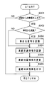
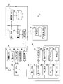
- a schematic configuration diagram showing a vehicle operation control system according to the first embodiment of the present invention same as above, explanatory diagram showing the operation control device and monitoring device of the vehicle connected to the control device by high-speed wireless communication. Same as above, explanatory diagram showing the monitoring area of the stereo camera Same as above, explanatory diagram showing road traffic detection information transmitted from the vehicle driving control device. Same as above, explanatory diagram showing road traffic detection information transmitted from the monitoring device Same as above, a flowchart showing a communication control routine in the communication control unit of the operation control device. Same as above, a flowchart showing a communication control routine in the communication control unit of the control device. Same as above, a flowchart showing a road traffic information recognition routine in the road traffic information recognition control unit of the control device.
- a flowchart showing a control information calculation routine in the travel control unit of the control device (No. 1). Same as above, a flowchart showing a control information calculation routine in the travel control unit of the control device (No. 2).
- Configuration diagram showing the main parts of the communication terminal according to the modified example Same as above, explanatory diagram showing the operation control device, communication terminal, and monitoring device of the vehicle connected to the control device by high-speed wireless communication.
- schematic configuration diagram showing a vehicle operation control system using a communication terminal A schematic configuration diagram showing a vehicle operation control system according to a second embodiment of the present invention.
- a flowchart showing a communication control routine in the communication control unit of the control device (No. 1).
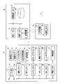
- FIG. 1 is a schematic configuration diagram showing a vehicle operation control system
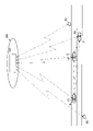
- FIG. 2 is a vehicle operation control device and a vehicle operation control device connected to a control device by high-speed wireless communication. It is explanatory drawing which shows the monitoring apparatus.
- the operation control system 1 in the present embodiment is provided in the operation control device 10 mounted on the vehicle 5 which is a moving body, the monitoring device 50 provided along the road, and the network environment NW. It is configured to include a plurality of control devices 70 composed of a narrow area server.
- the operation control device 10 has, for example, a camera unit 11 as an autonomous sensor for detecting the traveling environment outside the vehicle. Further, the operation control device 10 includes a communication control unit (hereinafter referred to as “communication_ECU”) 21, a travel control unit (hereinafter referred to as “travel_ECU”) 22, and an engine control unit (hereinafter referred to as “E / G_ECU”). 23, a power steering control unit (hereinafter referred to as "PS_ECU”) 24, a brake control unit (hereinafter referred to as "BK_ECU”) 25, and an alarm control unit (hereinafter referred to as "alarm_ECU”). ) And. Each of these control units 21 to 26 is connected via an in-vehicle communication line such as CAN (Controller Area Network).
- CAN Controller Area Network
- the camera unit 11 is fixed to the center of the upper part of the front part of the vehicle interior, for example.
- the camera unit 11 has, for example, an in-vehicle camera (stereo camera) including a main camera 11a and a sub camera 11b, and an image processing unit (IPU) 11c.
- an in-vehicle camera stereo camera
- IPU image processing unit
- the main camera 11a and the sub camera 11b sense, for example, the real space in front of the vehicle 5. That is, for example, the main camera 11a and the sub camera 11b are arranged symmetrically with respect to the center in the vehicle width direction of the vehicle 5, and stereo-image the front region Af (see FIG. 3) of the vehicle 5 from different viewpoints.
- the IPU 11c predeterminedly processes the image information of the front traveling environment of the vehicle 5 captured in stereo by both cameras 11a and 11b. As a result, the IPU 11c obtains distance information from the amount of positional deviation of the pixels indicating the corresponding targets in the left and right images, and generates image information (distance image information) including the distance information.
- a transceiver 13 for performing wireless communication with the control device 70 and the operation control device 10 of the other vehicle 5 is connected to the communication_ECU 21.
- the transceiver 13 is suitable for a high-reliability, low-delay communication system (for example, a fifth-generation mobile communication system).
- a camera unit 11 is connected to the input side of the communication_ECU 21, and the position (own vehicle position) of the vehicle 5 such as the acceleration sensor 14, the speed sensor 15, the gyro sensor 16, and the GNSS receiver 17 is estimated.
- the acceleration sensor 14 detects the front-rear acceleration and the lateral acceleration of the vehicle 5.
- the speed sensor 15 detects, for example, the rotational speed of each of the front, rear, left, and right wheels.
- the gyro sensor 16 detects the angular velocity or the angular acceleration of the vehicle 5.
- the GNSS receiver 17 receives positioning signals transmitted from a plurality of positioning satellites.
- the communication_ECU 21 is road traffic detection information (first road traffic detection information) including various information input from the above-mentioned camera unit 11, acceleration sensor 14, speed sensor 15, gyro sensor 16, GNSS receiver 17, and the like. To generate. Further, the communication_ECU 21 transmits the generated first road traffic detection information to the control device 70 at each preset control cycle.
- first road traffic detection information including various information input from the above-mentioned camera unit 11, acceleration sensor 14, speed sensor 15, gyro sensor 16, GNSS receiver 17, and the like. To generate. Further, the communication_ECU 21 transmits the generated first road traffic detection information to the control device 70 at each preset control cycle.
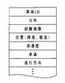
- the communication_ECU 23 has, for example, the vehicle ID of the vehicle 5, the transmission date and time, the distance image, the position (latitude, longitude) of the vehicle 5, the acceleration of the vehicle 5, the speed of the vehicle 5, and the like. And, road traffic detection information (first road traffic detection information) including the traveling direction of the vehicle 5 is generated. Then, the communication_ECU 21 transmits the generated first road traffic detection information to the control device 70 through the transceiver 18.
- the communication_ECU 21 receives the road map information (described later) appropriately transmitted from the control device 70 through the transceiver 18.
- the road map information transmitted from the control device 70 is map information that reflects the road traffic information that changes from moment to moment in real time. This road map information is generated based on the information collected from each vehicle 5 and each monitoring device 50 and the like existing in the predetermined control area.
- the communication_ECU 21 receives the control information (described later) appropriately transmitted from the control device 70 through the transceiver 18.
- This control information includes, for example, a target deceleration for controlling the deceleration of the vehicle 5 in an emergency where there is a possibility of collision with an obstacle.
- the communication_ECU 21 Upon receiving the target deceleration, the communication_ECU 21 outputs the received target deceleration to the E / G_ECU 23 and the BK_ECU 25.
- the E / G_ECU 23 and the BK_ECU 25 can execute the deceleration control based on the target deceleration as the interrupt control.
- control information includes, for example, a target steering angle for controlling the steering of the vehicle 5 in an emergency.
- the communication_ECU 21 Upon receiving the target steering angle, the communication_ECU 21 outputs the received target steering angle to the PS_ECU 24.
- the PS_ECU 24 can execute steering control based on the target steering angle as interrupt control.
- each control information transmitted from the control device 70 has priority over the control information (described later) calculated in the traveling_ECU 23 on the vehicle 5 side.
- the camera unit 11, the acceleration sensor 14, the wheel speed sensor 15, the gyro sensor 16, the GNSS receiver 17, and the like are one specific example as the first road traffic detection information acquisition means.
- the transceiver 18 corresponds to a specific example as the first communication device.
- the communication_ECU 21 can also transmit the first road traffic detection information to another vehicle 5 existing in the vicinity of the vehicle 5 through the transceiver 18 (see FIG. 2).
- Travel_ECU 22 calculates control information for vehicle 5 (own vehicle) based on the road map information received from the control device 70.
- the traveling_ECU 22 mainly calculates the control information related to the improvement of the convenience of the driver.
- the traveling_ECU 22 calculates the target acceleration / deceleration as control information for following vehicle-to-vehicle distance control (ACC: Adaptive Cruise Control) based on the road map information. That is, when the traveling_ECU 22 recognizes that the preceding vehicle exists in front of the own vehicle traveling lane based on the road map information, the traveling_ECU 22 follows the own vehicle while maintaining a predetermined inter-vehicle distance with respect to the preceding vehicle. Calculate the target acceleration / deceleration for.
- ACC Adaptive Cruise Control
- the traveling_ECU 22 calculates a target acceleration / deceleration for driving the own vehicle at a constant speed at a set vehicle speed. Then, the traveling_ECU 22 outputs the calculated target acceleration / deceleration to the E / G_ECU 23 and the BK_ECU 25. As a result, the E / G_ECU 23 and the BK_ECU 25 can execute acceleration / deceleration control based on the target acceleration / deceleration.
- the traveling_ECU 22 calculates the target steering angle as control information for lane center maintenance (ALKC: Active Lane Keep Centering) control based on the road map information. That is, the traveling_ECU 22 calculates a target steering angle for maintaining the own vehicle in the center of the own vehicle traveling lane based on the road map information. Then, the traveling_ECU 22 outputs the calculated target steering angle to the PS_ECU 24. As a result, the PS_ECU 24 can execute steering control based on the target steering angle.
- ALKC Active Lane Keep Centering
- a throttle actuator 27 is connected to the output side of the E / G_ECU 23.
- the throttle actuator 27 opens and closes the throttle valve of the electronically controlled throttle provided in the throttle body of the engine. That is, the throttle actuator 27 adjusts the intake air flow rate by opening and closing the throttle valve by the drive signal from the E / G_ECU 23. As a result, the throttle actuator 27 generates a desired engine output.
- An electric power steering motor 28 is connected to the output side of the PS_ECU 24.
- the electric power steering motor 28 applies steering torque to the steering mechanism by the rotational force of the motor. That is, the electric power steering motor 28 generates a desired steering angle by the drive signal from the PS_ECU 24.
- the brake actuator 29 is connected to the output side of the BK_ECU 25.
- the brake actuator 29 adjusts the brake hydraulic pressure supplied to the brake wheel cylinders provided on each wheel. That is, when the brake actuator 29 is driven by the drive signal from the BK_ECU 25, the brake actuator 29 generates a braking force for each wheel through the brake wheel cylinder. As a result, the brake actuator 29 forcibly decelerates the vehicle 5.
- the alarm device 30 is connected to the output side of the alarm_ECU 26.
- the alarm device 30 issues a predetermined alarm to the driver.
- the alarm device 30 is composed of, for example, a multi-information display or a speaker provided on the instrument panel. That is, the alarm device 30 generates a predetermined warning display or alarm sound to the driver by the drive signal from the alarm_ECU 26.
- the E / G_ECU23, PS_ECU24, and BK_ECU25 correspond to a specific example as an operation control execution means.
- the monitoring device 50 is, for example, a roadside infrastructure for observing a driving environment.
- the monitoring device 50 is arranged at a fixed point along the roadside at predetermined intervals.
- the monitoring device 50 includes, for example, a camera unit 51 and a communication_ECU 52.
- the camera unit 51 is composed of, for example, a monocular camera.
- the camera unit 51 is arranged, for example, so that the optical axis is inclined at a predetermined depression angle from above the road side toward the road surface. As a result, the camera unit 51 detects image information including vehicles traveling on the road.
- a transceiver 53 for performing wireless communication with the control device 70 is connected to the communication_ECU 52.
- the transceiver 53 is suitable for a high-reliability, low-delay communication system (for example, a fifth-generation mobile communication system).
- a camera unit 51 is connected to the input side of the communication_ECU 52.
- the communication_ECU 52 generates road traffic detection information (second road traffic detection information) including image information input from the above-mentioned camera unit 51. Further, the communication_ECU 53 transmits the generated second road traffic detection information to the control device 70 at each preset control cycle.
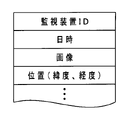
- the communication_ECU 52 generates road traffic detection information including the ID of the monitoring device 50, the transmission date / time, the image, the position (latitude, longitude) of the monitoring device 50, and the like. Then, the communication_ECU 52 transmits the generated road traffic detection information to the control device 70 through the transceiver 53.
- the camera unit 51 corresponds to a specific example as a second road traffic detection information acquisition means.
- the transceiver 53 corresponds to a specific example as a third communication device.
- the control device 70 is, for example, an edge server (so-called MEC server) in a network environment by edge computing, and is arranged in each predetermined control area.
- the control device 70 includes, for example, a communication_ECU 71, a road traffic information recognition control unit (hereinafter referred to as information recognition_ECU) 72, and a travel control unit (hereinafter referred to as "travel_ECU") 73. It is configured.
- Each of these control units 71 to 73 is connected via a predetermined communication line.
- each of the control units 71 to 73 has higher performance specifications than each control unit mounted on the vehicle 5. It should be noted that each control unit 71 to 73 may be configured by a single control unit.
- a transceiver 74 for performing wireless communication between the operation control device 10 of each vehicle and each monitoring device 50 is connected to the communication_ECU 71.
- the transceiver 74 is suitable for a high-reliability, low-delay communication system (for example, a fifth-generation mobile communication system).
- the communication_ECU 71 When the transmitter / receiver 74 receives the road traffic detection information from the operation control device 10 and each monitoring device 50 of each vehicle 5, the communication_ECU 71 outputs the received road traffic detection information to the information recognition_ECU 72.
- the communication_ECU 72 transmits the input control information to the corresponding vehicle 5 through the transceiver 74.
- the communication_ECU 72 transmits the input road map information to each vehicle 5 through the transmitter / receiver 74.
- the transceiver 74 corresponds to a specific example as the second communication device.
- a high-precision road map database 75 is connected to the information recognition_ECU 72.
- the high-precision road map database 75 is a large-capacity storage medium such as an HDD.
- the high-precision road map database 75 stores high-precision road map information (dynamic map) as information required for controlling the running of each vehicle 5 traveling on the road.
- the high-precision road map information has three layers of information, which are mainly static information constituting road information and quasi-dynamic information preliminary dynamic information mainly constituting traffic information.
- Static information is composed of information that is required to be updated frequently within one month, such as roads and structures on roads, lane information, road surface information, and permanent regulation information.
- Semi-dynamic information is updated within 1 minute, for example, actual traffic congestion status and driving restrictions at the time of observation, temporary driving obstacle status such as falling objects and obstacles, actual accident status, narrow area weather information, etc. It is composed of information that requires frequency.
- Dynamic information is, for example, information transmitted / exchanged between moving objects, information on currently displayed signals, information on pedestrians / two-wheeled vehicles in an intersection, information on vehicles traveling straight on an intersection, etc. within 1 second. It is composed of information that requires the update frequency.
- Such road map information is maintained and updated in a cycle until the next information is received from the operation control device 10 and each monitoring device 50 of each vehicle 5.
- the updated information is appropriately output to the communication_ECU 71 and the traveling_ECU 73.
- As the road map information to be output to the communication_ECU 71 it is also possible to output all the road map information in the control area. However, when considering the communication load with the communication_ECU 21 on the vehicle 5 side, only the road map information necessary for each vehicle 5 to calculate the control information in the traveling_ECU 23 is extracted, and the ID of each vehicle 5 is supported. It is desirable to output each as individual road map information attached.
- the information recognition_ECU 72 When updating the road map information, the information recognition_ECU 72 analyzes the road traffic detection information received from the operation control device 10 and each monitoring device 50 of each vehicle 5. As a result, the information recognition_ECU 72 performs the recognition process of the road traffic information.
- the information recognition_ECU 72 upon receiving the road traffic detection information from the driving control device 10, the information recognition_ECU 72 recognizes the current position of the vehicle 5 on the road map, and also recognizes the moving direction and the moving speed of the vehicle 5.
- the information recognition_ECU 72 obtains a lane dividing line that divides the road around the corresponding vehicle 5 based on the received distance image information and the like. Further, the information recognition_ECU 72 obtains the road curvature [1 / m] of each lane marking that divides the left and right of the traveling path, and the width (lane width) between the lane markings.
- the information recognition_ECU 72 performs predetermined pattern matching or the like on the distance image information. As a result, the information recognition_ECU 72 recognizes three-dimensional objects such as guardrails and curbs existing along the road, and pedestrians, two-wheeled vehicles, and vehicles other than two-wheeled vehicles existing on the road.
- the information recognition_ECU 72 for example, the type of the three-dimensional object, the distance to the three-dimensional object, the speed of the three-dimensional object, and the like are recognized.
- the information recognition_ECU 72 performs a well-known image recognition process or the like based on the received image information or the like. As a result, the information recognition_ECU 72 performs the recognition process of the road traffic information.
- the information recognition_ECU 72 stores the road traffic information in the high-precision road map database 75 based on the recognized road traffic information.
- the road map information is updated at any time. This information update is performed not only for static information but also for quasi-dynamic information and dynamic information.
- the road map information is configured to include the latest road traffic information acquired by communication with the outside of the control device 70, and information on moving objects such as vehicles traveling on the road is updated in real time.
- the information recognition_ECU 72 corresponds to a specific example as a road traffic information recognition means.
- Travel_ECU 73 calculates control information for each vehicle 5 existing in the control area of the control device 70. As this control information, the traveling_ECU 73 calculates at least control information for each vehicle 5 to urgently avoid a collision with an obstacle.
- various programs for calculating control information and the like in the traveling_ECU 73 can be updated to the latest programs at any time through, for example, the network environment NW.
- the traveling_ECU 73 detects an obstacle that is likely to collide with the vehicle 5 in front of the traveling path of the vehicle 5 based on the road map information reflecting the road traffic information.
- the traveling_ECU 73 detects an obstacle.
- the control information for controlling the emergency brake (AEB (Autonomous Emergency Braking)) for stopping the vehicle in front of the obstacle is calculated.
- the obstacle in the present embodiment means a three-dimensional object that may collide with the vehicle 5.
- the obstacle in the present embodiment means a three-dimensional object in which at least a part of the obstacle 5 is lapped with the vehicle 5 in front of the traveling path of the vehicle 5.
- This obstacle includes not only the other vehicle 5 and the like stopped near the shoulder of the road, but also the preceding vehicle 5 which suddenly decelerates or suddenly stops in front of the vehicle 5, and a pedestrian who crosses the traveling road.
- the control information for emergency brake control is set based on the obstacle recognized by the information recognition_ECU 72.
- the control information for the emergency brake control for example, the control information for the primary brake control and the control information for the secondary brake control are sequentially and stepwise set.
- the primary brake control is an alarm brake control for encouraging the driver to perform a collision avoidance operation with an obstacle.
- This primary brake control is a slow brake control for decelerating the vehicle 5 using a relatively small deceleration a0.
- the secondary brake control is the main brake control performed when the driver does not perform an appropriate collision avoidance operation with respect to the primary brake control.
- This secondary brake control is a strong brake control that decelerates the vehicle 5 until the relative speed with the obstacle becomes "0" by using a deceleration ap larger than the primary brake control.
- the control information for these brake controls is set when the relationship between the relative speed Vrel and the relative distance D between the vehicle 5 and the obstacle becomes equal to or less than the threshold value.
- the traveling_ECU 73 calculates the brake control start distances D1th and D2th, which are distance threshold values, from the relationship between the relative speed Vrel between the vehicle 5 and the obstacle and the lap ratio Rap.
- D1th and D2th a map for setting the primary brake control start distance and a map for setting the secondary brake control start distance are preset and stored in the traveling_ECU 73 based on experiments and simulations. Has been done.
- the lower the relative speed Vrel the smaller the distance threshold is set to delay the deceleration start timing
- the lower the lap ratio R the smaller the distance threshold is set to start deceleration. It is set to delay the timing. That is, each map is set so that the lower the relative speed Vrel and the lower the lap ratio R, the more room is left for the driver to avoid a collision with an obstacle by his / her own driving operation.
- the traveling_ECU 73 sets the target deceleration a0 as control information for the vehicle 5.
- the traveling_ECU 73 uses the target deceleration ap as control information for the vehicle 5. To set.
- the collision margin time TTC (Time To Collision), which will be described later, is a parameter substantially synonymous with the relative distance D in brake control. Therefore, it is also possible to use the collision margin time TTC as a parameter indicating the relationship between the relative velocity Vrel and the relative distance D.
- the traveling_ECU 73 calculates the collision margin time TTC (Time To Collision), which is the time until the vehicle 5 collides with an obstacle.
- the collision margin time TTC is, for example, a value obtained by dividing the relative distance D between the vehicle 5 and the obstacle in front by the relative speed Vrel between the vehicle 5 and the obstacle in front ((relative distance D) / (relative speed Vrel)). ) Is calculated.
- the traveling_ECU 73 determines that it is difficult to avoid a collision with an obstacle by braking control. As a result, the traveling_ECU 73 calculates control information for emergency steering (AES (Autonomous Emergency Steering)) control in order to avoid an emergency collision with an obstacle due to steering.
- AES Automatic Emergency Steering
- the threshold value Tth is a threshold value for determining whether or not there is a time margin for avoiding a collision between the vehicle 5 and an obstacle by emergency braking control in relation to the collision margin time TTC.
- the traveling_ECU 73 calculates a target lateral position for the vehicle 5 to avoid a collision with an obstacle. Further, the traveling_ECU 73 sets, for example, the vehicle position at the time when the collision margin time TTC becomes equal to or less than the setting threshold value Tth as the control start position. Further, the traveling_ECU 73 has, as a target path for emergency steering control, a first target path from the control start position to an intermediate position between the control start position and the target lateral position, and a first target path from the intermediate position to the target lateral position. Calculate the target route of 2. The first target path and the second target path are calculated using the lateral acceleration (time change rate of acceleration) allowed according to the vehicle speed. Then, the traveling_ECU 73 sets the target steering angle for driving the vehicle 5 along the target route as control information.
- the traveling_ECU 73 also appropriately provides the control information for collision avoidance to the other vehicle 5 as necessary. Calculate.
- Each control information calculated in this way is output from the traveling_ECU 73 to the communication_ECU 71.
- the communication_ECU 71 transmits each control information to the corresponding vehicle 5 through the transceiver 74.
- the traveling_ECU 73 corresponds to a specific example as a control information calculation means.
- the traveling_ECU 73 can set direct control instruction values for various actuators of each vehicle 5 instead of target values for various controls as control information. That is, the traveling_ECU 73 is controlled to be output from the E / G_ECU 23 and the BK_ECU 25 to the throttle actuator 27 and the brake actuator 29 as control information for the primary brake control in the emergency brake control, for example, instead of the target deceleration a0. It is also possible to calculate the indicated value (control indicated value including the feedback correction amount and the like).
- the traveling_ECU 73 is output from the E / G_ECU 23 and the BK_ECU 25 to the throttle actuator 27 and the brake actuator 29 as control information for the secondary brake control in the emergency brake control, for example, instead of the target deceleration ap. It is also possible to calculate the control instruction value (control instruction value including the feedback correction amount and the like). Further, the traveling_ECU 73 is a control instruction for emergency steering control, for example, a control instruction value (a control instruction considering a feedback correction amount or the like) output from the PS_ECU 24 to the electric power steering motor 28 instead of the target steering angle. Value) can also be set.
- the communication_ECU 21 checks in step S101 whether or not the vehicle 5 exists in the communication area (control area) of the control device 70.
- step S101 determines that the vehicle 5 exists outside the communication range (step S101: NO)
- the communication_ECU 21 exits the routine as it is.
- step S101 determines whether or not the vehicle 5 is within the communication range (step S101: YES).
- step S102 the communication_ECU 21 checks whether or not a set time (for example, 200 msec) has elapsed since the last transmission of the first road traffic detection information.
- step S102 when it is determined in step S102 that the set time has elapsed (step S102: YES), the communication_ECU 21 proceeds to step S103.
- step S103 the communication_ECU 21 transmits the first road traffic detection information through the transceiver 18, and then proceeds to step S104.
- step S102 determines whether the set time has not elapsed. If it is determined in step S102 that the set time has not elapsed (step S102: NO), the communication_ECU 21 proceeds to step S104 as it is.
- step S104 the communication_ECU 21 checks whether or not control information is received from the control device 70 corresponding to the control area where the vehicle 5 currently exists through the transceiver 18.
- step S104 determines whether the control information has not been received (step S104: NO). Then, when it is determined in step S104 that the control information has not been received (step S104: NO), the communication_ECU 21 proceeds to step S109.
- step S104 if it is determined in step S104 that the control information has been received (step S104: YES), the communication_ECU 21 proceeds to step S105.
- step S105 the communication_ECU 21 checks whether or not the received control information includes the target deceleration.
- step S105 when it is determined in step S105 that the received control information includes the target deceleration (step S105: YES), the communication_ECU 21 proceeds to step S106.
- step S106 the communication_ECU 21 outputs the target deceleration to the E / G_ECU23, BK_ECU25, and alarm_ECU26, and then proceeds to step S107.
- the E / G_ECU 23 and BK_ECU 25 perform emergency braking control for obstacles based on the input target deceleration.
- the alarm_ECU 26 a predetermined alarm control according to the target deceleration is appropriately performed.
- step S105 determines whether the received control information does not include the target deceleration (step S105: NO). If it is determined in step S105 that the received control information does not include the target deceleration (step S105: NO), the communication_ECU 21 proceeds to step S107 as it is.
- the communication_ECU 21 checks whether or not the received control information includes the target steering angle.
- step S107 when it is determined in step S107 that the received control information includes the target steering angle (step S107: YES), the communication_ECU 21 proceeds to step S108.
- step S108 the communication_ECU 21 outputs the target steering angle to the PS_ECU 24 and the alarm_ECU 26, and then proceeds to step S109.
- the SP_ECU 24 performs emergency steering control for obstacles based on the input target steering angle.
- the alarm_ECU 26 a predetermined alarm control according to the target steering angle is appropriately performed.
- step S107 if it is determined in step S107 that the received control information does not include the target steering angle (step S107: NO), the communication_ECU 21 proceeds to step S109 as it is.
- step S109 the communication_ECU 21 checks whether or not the road map information is received from the control device 70 corresponding to the control area where the vehicle 5 currently exists through the transceiver 18.
- step S109 determines that the road map information has not been received (step S109: NO)
- the communication_ECU 21 exits the routine as it is.
- step S109 if it is determined in step S109 that the road map information has been received (step S109: YES), the communication_ECU 21 proceeds to step S110.
- step S110 the communication_ECU 21 outputs the received road map information to the traveling_ECU 22, and then exits the routine.
- step S102 and step S103 the same processing as in step S102 and step S103 described above is performed in the communication_ECU 52 of the monitoring device 50. As a result, the second road traffic detection information is transmitted to the control device 70.
- the communication_ECU 71 checks in step S201 whether or not information from the outside has been received. That is, the communication_ECU 71 receives at least one of the first road traffic detection information from the operation control device 10 of the vehicle 5 existing in the control area and the second road traffic detection information from the monitoring device 50. Find out if you did.
- step S201 when it is determined in step S201 that the information from the outside has been received (step S201: YES), the communication_ECU 71 proceeds to step S202.
- step S202 the communication_ECU 71 outputs the received information to the information recognition_ECU 72, and then proceeds to step S203.
- step S201 determines whether the information from the outside is not received (step S201: NO). If it is determined in step S201 that the information from the outside is not received (step S201: NO), the communication_ECU 71 proceeds to step S203 as it is.
- the communication_ECU 71 checks whether or not the control information has been input from the traveling_ECU 73.
- step S203 when it is determined in step S203 that the control information has been input (step S203: YES), the communication_ECU 71 proceeds to step S204.
- step S204 the communication_ECU 71 transmits the control information to the vehicle 5 having the ID corresponding to the input control information through the transceiver 74, and then proceeds to step S205.
- step S203 determines whether the control information has been input (step S203: NO) or not been input (step S203: NO). If it is determined in step S203 that the control information has not been input (step S203: NO), the communication_ECU 71 proceeds to step S205 as it is.
- the communication_ECU 71 checks whether or not the newly updated road map information is input from the information recognition_ECU 72.
- step S205 when it is determined in step S205 that the road map information has been input (step S205: YES), the communication_ECU 71 proceeds to step S206.
- step S205 the communication_ECU 71 exits the routine after transmitting the input road map information to each vehicle 5 in the control area.
- step S205 if it is determined in step S205 that the road map information has not been input (step S205: NO), the communication_ECU 71 exits the routine as it is.
- the information recognition_ECU 72 checks whether or not information from the outside is input through the communication_ECU 71.
- step S301 when it is determined that the information from the outside is not input (step S301: NO), the information recognition_ECU 72 exits the routine as it is.
- step S301 if it is determined in step S301 that information from the outside has been input (step S301: YES), the information recognition_ECU 72 proceeds to step S302.
- step S302 the information recognition_ECU 72 checks whether or not the input information is information from the vehicle 5. That is, the information recognition_ECU 72 checks whether or not the input information is the first road traffic detection information.
- step S302 when it is determined in step S302 that the input information is the information from the vehicle 5 (step S302: YES), the information recognition_ECU 72 proceeds to step S303. Then, in step S303, the information recognition_ECU 72 recognizes the current position of the vehicle 5 on the road map, the traveling direction of the vehicle 5, the speed of the vehicle 5, and the like based on the first road traffic detection information, and then steps. Proceed to S304.
- step S302 when it is determined that the input information is not the information from the vehicle 5 (step S302: NO), that is, when it is determined that the input information is the second road traffic detection information, the information.
- the recognition_ECU 72 proceeds to step S304 as it is.
- the information recognition_ECU 72 recognizes the road traffic information based on the input road traffic detection information.
- the information recognition_ECU 72 uses the vehicle position and the traveling direction recognized in step S303 as a reference to lane marking lines and lane-to-lane widths on the road. , Recognize various information such as three-dimensional objects such as other vehicles and pedestrians. Further, the information recognition_ECU 72 recognizes the moving speed and the like of various three-dimensional objects based on the relative speed with the vehicle 5.
- the information recognition_ECU 72 uses the coordinates of the monitoring device 50 and the optical axis direction of the camera unit 51 as reference to the lane marking line on the road. , The width between lanes, and various information such as three-dimensional objects such as other vehicles and pedestrians are recognized. Further, the information recognition_ECU 72 recognizes the moving speed and the like of various three-dimensional objects.
- step S304 the information recognition_ECU 72 updates the road map information using the road traffic information recognized in step S304 and the like, and then proceeds to step S306.
- step S305 when proceeding from step S305 to step S306, the information recognition_ECU 72 outputs the road map information updated in step S305 to the communication_ECU 71 and the traveling_ECU 73, and then exits the routine.
- the travel_ECU 73 exists in the control area in step S401 based on the road traffic information (more specifically, based on the road map information reflecting the latest road traffic information). It is determined whether or not the vehicle 5 may collide with an obstacle.
- step S402 as a result of the determination in step S401 described above, it is investigated whether or not there is a vehicle 5 that may collide with an obstacle.
- step S402 determines whether there is no vehicle 5 that may collide with an obstacle (step S402: NO). If it is determined in step S402 that there is no vehicle 5 that may collide with an obstacle (step S402: NO), the traveling_ECU 73 exits the routine as it is.
- step S402 determines whether there is a vehicle 5 that may collide with an obstacle (step S402: YES). If it is determined in step S402 that there is a vehicle 5 that may collide with an obstacle (step S402: YES), the traveling_ECU 73 proceeds to step S403. In step S403, the traveling_ECU 73 extracts a vehicle 5 having a possibility of collision from the vehicles 5 existing in the control area.
- step S404 as the control information for each vehicle 5 extracted in step S403, the target deceleration for each vehicle 5 to avoid the collision with the obstacle by the emergency braking control is calculated.
- the traveling_ECU 73 examines whether or not each vehicle 5 can avoid a collision with an obstacle by emergency braking control.
- step S405 YES
- the traveling_ECU 73 proceeds to step S407 as it is.
- step S405 when it is determined in step S405 that collision avoidance with an obstacle by emergency braking control is impossible (step S405: NO), in the traveling_ECU 73, each vehicle 5 is urgently used as control information for the corresponding vehicle 5.
- the target steering angle (target steering amount) for avoiding a collision with an obstacle due to steering control is calculated.
- step S405 or step S406 the traveling_ECU 73 outputs the control information calculated for each vehicle 5 to the communication_ECU 71, and then proceeds to step S408.
- step S408 when the collision avoidance control of the corresponding vehicle 5 is performed based on the above-mentioned control information, whether or not another vehicle 5 having an influence exists in the control area. To find out. That is, when the traveling_ECU 73 performs collision avoidance control of the vehicle 5 based on the above-mentioned control information, another vehicle 5 that may collide with the vehicle 5 for which the collision avoidance control is performed is newly generated. Find out if you want to.
- step S408 when it is determined in step S408 that the other vehicle 5 having an influence does not exist (step S408: NO), the traveling_ECU 73 exits the routine as it is.
- step S408 determines whether another affected vehicle 5 exists (step S408: YES). If it is determined in step S408 that another affected vehicle 5 exists (step S408: YES), the traveling_ECU 73 proceeds to step S409. In step S409, the traveling_ECU 73 extracts a new vehicle 5 in which a collision possibility has occurred.
- step S409 the extracted vehicles 5 are subjected to the same processing as in steps S404 to S407 described above in the processing from step S410 to step S413, and then the process returns to step S408.
- the vehicle operation control system 1 is provided in the camera unit 11 mounted on the vehicle 5, the transmitter / receiver 18 mounted on the vehicle 5, and the monitoring device 50 arranged at a fixed point on the roadside.
- Information recognition_ECU 72 that recognizes road traffic information based on the first road traffic detection information received by the transmitter / receiver 74 and the second road traffic detection information received by the transmitter / receiver 74 through the transmitter / receiver 53, and a control device.
- the travel_ECU 73 provided in 70 and calculating the control information of the vehicle 5 existing in the control area based on the road traffic information, and the control information mounted on the vehicle 5 and received by the transmitter / receiver 18 through the transmitter / receiver 74. It is configured to include an E / G_ECU 23, a PS_ECU 24, and a BK_ECU 25 that perform operation control. As a result, the latest driving control can be applied to the vehicle 5 having various specifications without mounting a complicated system on the vehicle 5.
- the information recognition_ECU 72 of the control device 70 combines the road traffic information in the control area based on the first and second road traffic detection information transmitted from the operation control device 10 of each vehicle 5 and each monitoring device 50. Recognize. Therefore, the information recognition_ECU 72 can accurately and efficiently recognize the road traffic information around the vehicle 5. Then, based on the road traffic information recognized by the information recognition_ECU 72, the traveling_ECU 73 of the control device 70 calculates the control information (control parameter) of each vehicle 5. Therefore, it is not necessary to provide multiple autonomous sensors or the like on each vehicle 5, and it is not necessary to mount a high-performance control unit or the like on each vehicle 5. Therefore, the system on the vehicle 5 side can be significantly simplified.
- the running_ECU 73 of the control device 70 calculates the control information of each vehicle 5, it is easy to upgrade the version of the program or the like for calculating the control information, and the latest operation control is applied to the vehicle 5 of each specification. Can be deployed.
- each vehicle 5 has at least one autonomous sensor such as a camera unit 11. Therefore, the information recognition_ECU 72 can accurately recognize even a sudden jump of a pedestrian, which may be difficult for the monitoring device 50 to catch.
- the road traffic information can be recognized in real time, and the control information based on the road traffic information recognized in real time can be reflected in each vehicle 5 in real time.
- the traveling_ECU 73 calculates control information for collision avoidance and the like for other vehicles 5 affected by the behavior of the vehicle 5 for which control information is set, as necessary. Therefore, control for avoiding a collision with another vehicle 5 can be quickly executed. That is, the calculation of the control information for each vehicle 5 existing in the control area is collectively performed by the traveling_ECU 73 in the control device 70. As a result, for example, before the vehicle 5 for which the control information is set actually causes a behavior for collision avoidance or the like, the influence of the vehicle 5 on the other vehicle 5 can be determined in advance from the control information for the vehicle 5. Can be grasped. Therefore, the control information for the other vehicle 5 can be calculated in advance, and the control for avoiding the collision with the other vehicle 5 can be realized with good responsiveness.
- the communication_ECU 21, traveling_ECU22, E / G_ECU23, PS_ECU24, BK_ECU25, alarm_ECU26, communication_ECU52, communication_ECU71, information recognition_ECU72, traveling_ECU73, etc. are CPU, RAM, ROM, non-volatile storage. It is composed of a well-known microcomputer equipped with a unit and its peripheral devices.
- the ROM stores in advance fixed data such as a program executed by the CPU and a data table. All or part of the functions of the processor may be configured by a logic circuit or an analog circuit. Further, the processing of various programs may be realized by an electronic circuit such as FPGA.
- the present invention is not limited to this, and for example, a camera unit made of a stereo camera.
- a camera unit consisting of a monocular camera, a millimeter-wave radar, a lidar (Lidar: light detection and ranging), etc. can be applied.
- the monitoring device 50 instead of the camera unit 51 made of a monocular camera, a camera unit made of a stereo camera, a millimeter wave radar, a rider, or the like can be applied.
- a communication terminal 80 such as a smartphone or a mobile phone can be adopted. be.
- the communication terminal 80 has a camera unit 81, an acceleration sensor 84, a speed sensor 85, a gyro sensor 86, a GNSS receiver 87, etc. connected to the communication_ECU 82 as the first road traffic detection acquisition means. .. Further, the communication terminal 80 has a transceiver 88 connected to the communication_ECU 82 as the first communication device.
- the camera unit 81, the acceleration sensor 84, the speed sensor 85, the gyro sensor 86, the GNSS receiver 87, and the like include the camera unit 11, the acceleration sensor 14, the speed sensor 15, the gyro sensor 16, and the GNSS receiver 87 in the above-described embodiment.
- the configuration corresponds to the GNSS receiver 17 and the like.
- the communication_ECU 82 has a configuration corresponding to the communication_ECU 21 in the above-described embodiment.
- the transceiver 88 has a configuration corresponding to the transceiver 18 in the above-described embodiment. Therefore, detailed description of each of these configurations will be omitted.
- such a communication terminal 80 acquires the first road traffic detection information by being held by a pedestrian 100 or the like in the control area, and the acquired first road traffic detection. Information can be transmitted to the control device 70.
- the communication terminal 80 can be applied to a vehicle 5 equipped with an operation control device 10 having no camera unit, transceiver, or the like.
- the communication terminal 80 fixed to the dashboard or the like of the vehicle 5 can be connected to the operation control device 10 via a communication cable such as a USB (Universal Serial Bus) cable.
- the communication terminal 80 can acquire the first road traffic detection information and transmit the acquired first road traffic detection information to the control device 70.
- the communication terminal 80 can output the control information received from the control device 70 to the ECUs 23 to 26.
- control information related to the safety of each vehicle is calculated by the control device, and the control information of the control for convenience such as cruise control is separately provided for each vehicle.
- the configuration to be calculated in is described.
- control information and the like for convenience may be calculated in the control device.
- the traveling_ECU or the like provided in the operation control device of each vehicle can be omitted as appropriate.
- FIGS. 14 to 15 The same components as those of the first embodiment described above are designated by the same reference numerals, and the description thereof will be omitted as appropriate.
- This embodiment is an embodiment for reducing the information transmitted from the transceiver 74 of the control device 70 to the transceiver 18 of the operation control device 10.
- the information transmitted from the transceiver 74 of the control device 70 to the transceiver 18 of the operation control device 10 is control information related to ensuring the safety of the vehicle 5 (for example, emergency braking against obstacles). Control and emergency steering control) only.
- the transmission of the road map information from the transceiver 74 to the transceiver 18 is basically not performed.
- the communication_ECU 71 of the control device 70 performs only the processes of steps S201 to S204 in the above-mentioned first embodiment.
- the camera unit 11 has an information recognition unit 11d for recognizing road traffic information based on the distance image information generated by the IPU 11c. Is provided.
- the information recognition unit 11d calculates, for example, a lane lane marking that divides the road around the vehicle 5, a road curvature of each lane marking that divides the left and right sides of the travel path, and a lane width based on distance image information or the like. And so on. Further, the information recognition unit 11d performs recognition processing of various three-dimensional objects by, for example, performing predetermined pattern matching or the like on the distance image information.
- the road traffic information recognized by the information recognition unit 11d in this way is output to the traveling_ECU 22. Then, the travel_ECU 22 calculates control information for, for example, follow-up vehicle-to-vehicle distance control, lane center maintenance control, and the like, based on the road traffic information input from the information recognition unit 11d.
- a millimeter wave radar or a laser radar is used in addition to the camera unit 11 or in place of the camera unit 11. It is also possible to appropriately provide an autonomous sensor such as, and a locator unit or the like having road map information independent of the road map information of the control device 72.
- the information transmitted from the transceiver 74 of the control device 70 to the transceiver 18 of the vehicle 5 is limited to the control information for ensuring the safety of the vehicle 5.
- the communication load from the transceiver 74 to the transceiver 18 can be significantly reduced. Therefore, the control information calculated with high accuracy in the traveling_ECU 73 of the control device 70 can be instantly transmitted to the target vehicle 5, and the control for ensuring the safety of the vehicle 5 can be realized at a higher level. Can be done.
- the collision avoidance control based on the control information transmitted from the control device 70 is quickly used as interrupt control. Can be executed.
Landscapes
- Engineering & Computer Science (AREA)
- Transportation (AREA)
- Mechanical Engineering (AREA)
- Automation & Control Theory (AREA)
- Chemical & Material Sciences (AREA)
- Combustion & Propulsion (AREA)
- Human Computer Interaction (AREA)
- Physics & Mathematics (AREA)
- General Physics & Mathematics (AREA)
- Traffic Control Systems (AREA)
- Control Of Driving Devices And Active Controlling Of Vehicle (AREA)
- Regulating Braking Force (AREA)
Abstract
Description
Claims (3)
- 移動体に設けられ、第1の道路交通検出情報を取得する第1の道路交通検出情報取得手段と、
前記移動体に設けられた第1の通信機と、
管制エリア毎に配置された管制装置に設けられた第2の通信機と、
前記管制装置に設けられ、前記第1の通信機を通じて前記第2の通信機が受信した前記第1の道路交通検出情報に基づいて道路交通情報を認識する道路交通情報認識手段と、
前記管制装置に設けられ、前記管制エリア内に存在する車両の制御情報を前記道路交通情報に基づいて演算する制御情報演算手段と、
前記車両に搭載され、前記第2の通信機を通じて前記第1の通信機が受信した前記制御情報に基づいて運転制御を行う運転制御実行手段と、を備えたことを特徴とする車両の運転制御システム。 - 前記制御情報演算手段は、前記制御情報として、少なくとも、前記車両が障害物との衝突を緊急回避するための制御情報を演算することを特徴とする請求項1に記載の車両の運転制御システム。
- 道路交通検出情報を取得する道路交通検出情報取得手段と、
管制エリア毎に配置された管制装置に対して前記道路交通検出情報を送信するとともに、前記管制装置において演算された制御情報を受信する通信機と、
前記制御情報に基づいて運転制御を行う運転制御実行手段と、を備えたことを特徴とする車両の運転制御装置。
Priority Applications (4)
| Application Number | Priority Date | Filing Date | Title |
|---|---|---|---|
| US18/270,022 US20240067210A1 (en) | 2020-12-28 | 2021-12-23 | Driving control system for vehicle, and driving control apparatus for vehicle |
| CN202180087964.2A CN116783101A (zh) | 2020-12-28 | 2021-12-23 | 车辆的驾驶控制系统和车辆的驾驶控制装置 |
| DE112021006687.0T DE112021006687T5 (de) | 2020-12-28 | 2021-12-23 | Fahrsteuerungssystem für ein fahrzeug sowie fahrsteuerungsvorrichtung für ein fahrzeug |
| JP2022573047A JP7412603B2 (ja) | 2020-12-28 | 2021-12-23 | 車両の運転制御システム、及び、車両の運転制御装置 |
Applications Claiming Priority (2)
| Application Number | Priority Date | Filing Date | Title |
|---|---|---|---|
| JP2020219596 | 2020-12-28 | ||
| JP2020-219596 | 2020-12-28 |
Publications (1)
| Publication Number | Publication Date |
|---|---|
| WO2022145351A1 true WO2022145351A1 (ja) | 2022-07-07 |
Family
ID=82259415
Family Applications (1)
| Application Number | Title | Priority Date | Filing Date |
|---|---|---|---|
| PCT/JP2021/048013 Ceased WO2022145351A1 (ja) | 2020-12-28 | 2021-12-23 | 車両の運転制御システム、及び、車両の運転制御装置 |
Country Status (5)
| Country | Link |
|---|---|
| US (1) | US20240067210A1 (ja) |
| JP (1) | JP7412603B2 (ja) |
| CN (1) | CN116783101A (ja) |
| DE (1) | DE112021006687T5 (ja) |
| WO (1) | WO2022145351A1 (ja) |
Families Citing this family (1)
| Publication number | Priority date | Publication date | Assignee | Title |
|---|---|---|---|---|
| US20250296558A1 (en) * | 2024-03-20 | 2025-09-25 | Janice H. Nickel | Enhanced situational awareness of road objects |
Citations (3)
| Publication number | Priority date | Publication date | Assignee | Title |
|---|---|---|---|---|
| JP2008186082A (ja) * | 2007-01-26 | 2008-08-14 | Toyota Motor Corp | 情報作成システム |
| WO2016080452A1 (ja) * | 2014-11-19 | 2016-05-26 | エイディシーテクノロジー株式会社 | 自動運転制御装置 |
| JP2017194913A (ja) * | 2016-04-22 | 2017-10-26 | 株式会社東芝 | プローブ情報処理サーバ、プローブ車両、およびプローブ情報処理方法 |
Family Cites Families (5)
| Publication number | Priority date | Publication date | Assignee | Title |
|---|---|---|---|---|
| WO2009060581A1 (ja) * | 2007-11-05 | 2009-05-14 | Fujitsu Ten Limited | 周辺監視装置、安全走行支援システム、及び車両 |
| DE102015220640A1 (de) * | 2015-10-22 | 2017-04-27 | Robert Bosch Gmbh | Verfahren und Vorrichtung zum Verringern eines Kollisionsrisikos einer Kollision eines Kraftfahrzeugs mit einem Objekt |
| JP7032971B2 (ja) | 2018-03-29 | 2022-03-09 | 株式会社Subaru | 車両の運転支援システム |
| JP7239353B2 (ja) | 2019-03-12 | 2023-03-14 | 株式会社デンソー | 車両における制動支援制御装置、制動支援制御システムおよび制動支援制御方法 |
| JP7140067B2 (ja) * | 2019-07-12 | 2022-09-21 | 株式会社デンソー | 車両制御装置、車両制御方法、及びプログラム |
-
2021
- 2021-12-23 DE DE112021006687.0T patent/DE112021006687T5/de active Pending
- 2021-12-23 WO PCT/JP2021/048013 patent/WO2022145351A1/ja not_active Ceased
- 2021-12-23 JP JP2022573047A patent/JP7412603B2/ja active Active
- 2021-12-23 US US18/270,022 patent/US20240067210A1/en active Pending
- 2021-12-23 CN CN202180087964.2A patent/CN116783101A/zh active Pending
Patent Citations (3)
| Publication number | Priority date | Publication date | Assignee | Title |
|---|---|---|---|---|
| JP2008186082A (ja) * | 2007-01-26 | 2008-08-14 | Toyota Motor Corp | 情報作成システム |
| WO2016080452A1 (ja) * | 2014-11-19 | 2016-05-26 | エイディシーテクノロジー株式会社 | 自動運転制御装置 |
| JP2017194913A (ja) * | 2016-04-22 | 2017-10-26 | 株式会社東芝 | プローブ情報処理サーバ、プローブ車両、およびプローブ情報処理方法 |
Also Published As
| Publication number | Publication date |
|---|---|
| JPWO2022145351A1 (ja) | 2022-07-07 |
| DE112021006687T5 (de) | 2024-01-11 |
| JP7412603B2 (ja) | 2024-01-12 |
| US20240067210A1 (en) | 2024-02-29 |
| CN116783101A (zh) | 2023-09-19 |
Similar Documents
| Publication | Publication Date | Title |
|---|---|---|
| US10437257B2 (en) | Autonomous driving system | |
| US11636762B2 (en) | Image display device | |
| US11402844B2 (en) | Vehicle control apparatus, vehicle control method, and storage medium | |
| US11370442B2 (en) | Vehicle control device and control method | |
| US20210101600A1 (en) | Vehicle control device, vehicle control method, and storage medium | |
| US20200307595A1 (en) | Vehicle control device, vehicle control method, and storage medium | |
| JP7538656B2 (ja) | 車両の走行制御装置 | |
| JP7473277B2 (ja) | 車両の走行制御装置 | |
| US11479246B2 (en) | Vehicle control device, vehicle control method, and storage medium | |
| US11390302B2 (en) | Vehicle control device, vehicle control method, and program | |
| JP7610387B2 (ja) | 車両の走行制御装置 | |
| WO2018179359A1 (ja) | 車両制御システム、車両制御方法、および車両制御プログラム | |
| JP7531539B2 (ja) | 車両制御装置、車両制御方法、およびプログラム | |
| CN113646201A (zh) | 车辆用显示控制装置、车辆用显示控制方法、车辆用显示控制程序 | |
| JP2023150579A (ja) | 制御装置、制御方法、およびプログラム | |
| JP7509493B2 (ja) | 車両の走行制御装置 | |
| JP7616882B2 (ja) | 車両の運転制御システム、及び、車両の管制装置 | |
| JP2022061482A (ja) | 車両の走行制御装置 | |
| JP7633807B2 (ja) | 車両の運転制御システム | |
| JP7412603B2 (ja) | 車両の運転制御システム、及び、車両の運転制御装置 | |
| JP2023148089A (ja) | 車両制御装置、車両制御方法、およびプログラム | |
| US12479460B2 (en) | Control device, control method, and storage medium | |
| US11840222B2 (en) | Vehicle control method, vehicle control device, and storage medium | |
| JP7514158B2 (ja) | 運転診断装置 | |
| US20200307592A1 (en) | Vehicle control device, vehicle control method, and storage medium |
Legal Events
| Date | Code | Title | Description |
|---|---|---|---|
| 121 | Ep: the epo has been informed by wipo that ep was designated in this application |
Ref document number: 21915211 Country of ref document: EP Kind code of ref document: A1 |
|
| DPE1 | Request for preliminary examination filed after expiration of 19th month from priority date (pct application filed from 20040101) | ||
| ENP | Entry into the national phase |
Ref document number: 2022573047 Country of ref document: JP Kind code of ref document: A |
|
| WWE | Wipo information: entry into national phase |
Ref document number: 202180087964.2 Country of ref document: CN |
|
| WWE | Wipo information: entry into national phase |
Ref document number: 18270022 Country of ref document: US |
|
| WWE | Wipo information: entry into national phase |
Ref document number: 112021006687 Country of ref document: DE |
|
| 122 | Ep: pct application non-entry in european phase |
Ref document number: 21915211 Country of ref document: EP Kind code of ref document: A1 |