WO2022145221A1 - 開閉装置用の安全装置 - Google Patents
開閉装置用の安全装置 Download PDFInfo
- Publication number
- WO2022145221A1 WO2022145221A1 PCT/JP2021/046041 JP2021046041W WO2022145221A1 WO 2022145221 A1 WO2022145221 A1 WO 2022145221A1 JP 2021046041 W JP2021046041 W JP 2021046041W WO 2022145221 A1 WO2022145221 A1 WO 2022145221A1
- Authority
- WO
- WIPO (PCT)
- Prior art keywords
- speed
- opening
- internal
- tip
- plate
- Prior art date
- Legal status (The legal status is an assumption and is not a legal conclusion. Google has not performed a legal analysis and makes no representation as to the accuracy of the status listed.)
- Ceased
Links
Images




Classifications
-
- E—FIXED CONSTRUCTIONS
- E05—LOCKS; KEYS; WINDOW OR DOOR FITTINGS; SAFES
- E05F—DEVICES FOR MOVING WINGS INTO OPEN OR CLOSED POSITION; CHECKS FOR WINGS; WING FITTINGS NOT OTHERWISE PROVIDED FOR, CONCERNED WITH THE FUNCTIONING OF THE WING
- E05F5/00—Braking devices, e.g. checks; Stops; Buffers
- E05F5/02—Braking devices, e.g. checks; Stops; Buffers specially for preventing the slamming of swinging wings during final closing movement, e.g. jamb stops
-
- E—FIXED CONSTRUCTIONS
- E06—DOORS, WINDOWS, SHUTTERS, OR ROLLER BLINDS IN GENERAL; LADDERS
- E06B—FIXED OR MOVABLE CLOSURES FOR OPENINGS IN BUILDINGS, VEHICLES, FENCES OR LIKE ENCLOSURES IN GENERAL, e.g. DOORS, WINDOWS, BLINDS, GATES
- E06B3/00—Window sashes, door leaves, or like elements for closing wall or like openings; Layout of fixed or moving closures, e.g. windows in wall or like openings; Features of rigidly-mounted outer frames relating to the mounting of wing frames
- E06B3/32—Arrangements of wings characterised by the manner of movement; Arrangements of movable wings in openings; Features of wings or frames relating solely to the manner of movement of the wing
- E06B3/34—Arrangements of wings characterised by the manner of movement; Arrangements of movable wings in openings; Features of wings or frames relating solely to the manner of movement of the wing with only one kind of movement
- E06B3/42—Sliding wings; Details of frames with respect to guiding
- E06B3/46—Horizontally-sliding wings
-
- E—FIXED CONSTRUCTIONS
- E06—DOORS, WINDOWS, SHUTTERS, OR ROLLER BLINDS IN GENERAL; LADDERS
- E06B—FIXED OR MOVABLE CLOSURES FOR OPENINGS IN BUILDINGS, VEHICLES, FENCES OR LIKE ENCLOSURES IN GENERAL, e.g. DOORS, WINDOWS, BLINDS, GATES
- E06B7/00—Special arrangements or measures in connection with doors or windows
- E06B7/28—Other arrangements on doors or windows, e.g. door-plates, windows adapted to carry plants, hooks for window cleaners
- E06B7/36—Finger guards or other measures preventing harmful access between the door and the door frame
Definitions
- This disclosure relates to a safety device for a switchgear.
- a safety device for a switchgear equipped with a speed reducer is known (see Patent Document 1).
- the speed reducing device slows down the moving speed of the opening / closing movement of the door body to prevent fingers from being pinched between the door body and the frame body.
- the object of the present disclosure is to provide a safety device for a switchgear that can realize a small size and low cost.
- the present disclosure is a safety device for a switchgear capable of opening and closing an opening by opening and closing the door body, the speed reducing device for decelerating the moving speed of the opening and closing movement of the door body, and the speed reduction device decelerated by the speed reducing device.
- the present invention relates to a safety device for a switchgear provided with a stopper device for temporarily stopping the opening / closing operation of a door body.
- the safety device of the embodiment it is a figure explaining the operation that the tip portion of the arm plate decelerated by the deceleration device temporarily stops the shoji by the stopper part. It is a figure which shows the operation which the operation arm part returns a return movement path in the safety device of an embodiment.
- the "finding direction” means the surface direction of the glass in the shoji house housed in the opening 20a of the frame body 20 arranged in the building
- the "expected direction” means the above-mentioned glass.
- the outdoor side is described as “OUTSIDE” and the indoor side is described as “INSIDE”.
- the switchgear 1 of the present embodiment is a so-called sliding window, and as shown in FIG. 1, the frame body 20, the internal sash 30 (door body) and the external sash 40 fitted in the frame body 20 so as to be openable and closable. And a safety device 10.
- the opening / closing device 1 can open / close the opening 20a by opening / closing the inner sash 30 and the outer sash 40 in the left-right direction X.
- the safety device 10 is for the switchgear 1.
- the frame body 20 is framed in a rectangular shape by the upper frame 21, the lower frame 22, and the left and right vertical frames 23, 24.
- the upper frame 21 is formed in a long shape and extends in the finding direction at the upper part of the frame body 20.
- the upper frame 21 is formed so as to open downward.
- the lower frame 22 is formed in a long shape and extends in the finding direction at the lower part of the frame body 20.
- the lower frame 22 is formed so as to open upward.
- the left and right vertical frames 23 and 24 extend in the vertical direction at both ends of the upper frame 21 and the lower frame 22 in the finding direction.
- the left and right vertical frames 23 and 24 are formed in a long shape and form a side portion of the frame body 20.
- Both the inner sash 30 and the outer sash 40 are sliding doors, and by sliding them in the finding direction, the opening 20a of the frame body 20 is opened or closed, forming a so-called sliding window.
- the internal sash 30 has a rectangular frame 35 formed by a long upper stile 31, a lower stile 32, a left and right vertical stiles 33, and a door tip stile 34. And the glass 36 fitted and fixed in the frame 35, and the like.
- the shoji 40 has a rectangular frame 45 formed by a long upper stile 41, a lower stile 42, and left and right vertical stiles 43 and a door tip stile 44. And the glass 46 fitted and fixed in the frame 45, and the like.
- the left-right direction of FIG. 1 is referred to as the left-right direction X.
- the left-right direction X of the switchgear 1 is also the lateral direction of the internal sash 30.
- One side (left side in FIG. 1) of the switchgear 1 in the left-right direction X is referred to as the X1 side
- the other side (right side in FIG. 1) in the left-right direction X is referred to as the X2 side.
- the vertical direction is referred to as a vertical direction Z.
- the direction in which the internal sash 30 is closed on the X2 side (right side in FIG.
- the opening direction (direction of movement from the X2 side to the X1 side) on the X2 side (right side of FIG. 1) is referred to as a second movement direction D2.
- the safety device 10 is provided with a finger pinch prevention mechanism.
- the safety device 10 includes a stopper device 50 and a speed reducing device 80.
- the stopper device 50 includes a stopper device main body 60 and an operation arm unit 70.
- the stopper device main body 60 is fixed to the end side of the upper frame 21 of the frame body 20 on the X2 side in the left-right direction X, and is fixed to the upper portion of the opening 20a on the X2 side in the left-right direction X.
- the operation arm portion 70 is fixed to the upper part of the upper stile 31 of the inner sash 30 on the X2 side in the left-right direction X, thereby being fixed to the upper part of the inner sash 30 on the X2 side in the left-right direction X.
- the operation arm portion 70 is introduced into the stopper device main body 60 by moving the shoji screen 30 in the first moving direction D1.
- the safety device 10 is provided with a finger pinch prevention mechanism to prevent the internal sash 30 from colliding with the vertical frame 24 of the frame body 20. can.
- the stopper device 50 is similar to the operation of the operation example E1 of the internal sash 30 shown in FIG. 5 when the internal sash 30 is moved toward the deceleration device 80 at a movement speed slower than the first speed V1.
- the speed reducing device 80 does not slow down the moving speed of the shoji screen 30.
- the stopper device 50 is inside as in the operation examples E2 and E3 of the internal sash 30 shown in FIG. The load of the shoji 30 is received, and the moving speed of the internal shoji 30 is reduced by the speed reducing device 80.
- the stopper device 50 when the internal sash 30 decelerated by the decelerating device 80 is moved at a moving speed of the second speed V2 or higher, the stopper device 50 is like the operation example E3 of the internal sash 30 shown in FIG. The opening / closing operation of the shoji screen 30 is temporarily stopped.
- the stopper device 50 when the internal sash 30 decelerated by the decelerating device 80 is moved at a moving speed slower than the second speed V2, the stopper device 50 is as shown in the operation example E2 of the internal sash 30 shown in FIG. The opening / closing operation of the shoji 30 is not stopped.
- the stopper device main body 60 includes a base member 61, an inclined guide portion 62, a path extending plate 63, a receiving portion 64, and a stopper portion 66. Further, the stopper device main body 60 includes a first movement path K1 (upstream path), a fall guidance communication portion 65 (guidance portion), and a movement path for the tip portion 721 of the arm plate 72 of the operation arm portion 70 to move. It has a second movement route K2 (downstream side route) and a return movement route K3 (return route).
- the base member 61 has a top plate 611 and a side plate 612.
- the top plate 611 has a width in the prospective direction and extends in the left-right direction X, and is fixed to the upper frame 21.
- the side plate 612 extends downward from the indoor end of the top plate 611 in the prospect direction.
- the first movement route K1 is a route that passes through the upper surface side of the inclined guide portion 62 and the upper surface side of the route extending plate 63 to the receiving portion 64.
- the first movement path K1 is a path in which the tip portion 721 of the arm plate 72 can be moved in the first movement direction D1 when the tip portion 721 (moving portion) of the arm plate 72 heads toward the receiving portion 64. be.
- the second movement path K2 (downstream side path) is in the left-right direction of the first movement path K1 via the fall guidance communication portion 65 formed at the lower part of the end portion of the left-right direction X of the first movement path K1 on the X2 side. It is formed so as to communicate with the lower side of the end portion of X on the X2 side, and extends from below the end portion on the X2 side of the left-right direction X of the first movement path K1 to the X2 side of the left-right direction X.
- the second movement path K2 is a path in which the tip end portion 721 of the arm plate 72 of the operation arm portion 70 guided by the fall guidance communication portion 65 can be moved in the first movement direction D1.
- the return movement path K3 is formed so as to extend from the end side opposite to the end on the first movement direction D1 side in the second movement path K2 to the first movement path K1 side and join the upstream side of the first movement path K1. It is a route to do.
- the return movement path K3 extends horizontally from the X2 side of the left-right direction X to the X1 side, passes through the lower side of the path extension plate 63 and the lower side of the inclined guide portion 62, and is the first movement path K1. It is a route that joins the upstream side.
- the inclined guide portion 62 is formed in a plate shape that is inclined from the lower side to the upper side from the X1 side to the X2 side in the left-right direction X.
- the tilt guide portion 62 is connected to the end of the path extending plate 63 on the X1 side in the left-right direction X so that the base end on the X2 side in the left-right direction X can rotate about the rotation axis J3 extending in the prospective direction. ..
- the tilt guide portion 62 can rotate about the rotation axis J3 in a state where the downward rotation angle is restricted by a predetermined angle.
- the inclined guide portion 62 is arranged at a portion where the first movement path K1 and the return movement path K3 meet, and when the tip end side pin 73 of the operation arm portion 70 moves on the first movement path K1, the return movement path K3 is provided.
- the tip side pin 73 moves from the return movement path K3 to the first movement path K1 by closing to form the first movement path K1, the tip side pin 73 pushes up the rotation shaft J3 from the closed position. Rotating upward to the center, the tip end side pin 73 opens the path for moving from the return moving path K3 to the first moving path K1.
- the inclined guide portion 62 functions as an opening / closing portion for opening / closing the return movement path K3 by opening / closing the X1 side of the return movement path K3 in the left-right direction X when the arm plate 72 returns to the return movement path K3. do.
- the path extending plate 63 is formed in the shape of a flat plate extending from the end of the inclined guide portion 62 on the X2 side in the left-right direction X to the X2 side.
- the outdoor end of the path extending plate 63 in the prospective direction is located at the same position as the outdoor end of the inclined guide portion 62 in the prospective direction.
- the receiving portion 64 is arranged at the end of the first movement path K1 on the X2 side in the left-right direction X.
- a speed reducing device 80 is connected to the surface of the receiving portion 64 on the X2 side in the left-right direction X.
- the receiving unit 64 receives the load of the tip portion 721 of the arm plate 72 and decelerates the moving speed of the internal obstacle 30 by the speed reducing device 80. ..
- the tip portion 721 of the arm plate 72 does not contact the receiving portion 64 or comes into contact with the receiving portion 64 in front of the receiving portion 64.
- the side pin 73 is guided by the fall guidance communication portion 65 (guidance portion) communicating with the second movement path K2, and is guided downward (intersection direction) by the fall guidance communication portion 65 (guidance portion).
- the receiving portion 64 has a plate-shaped collision plate 641 extending in the vertical direction Z and the prospective direction, and a regulating portion 642.
- the collision plate 641 is fixed to the base member 61 below the upper surface plate 611 of the base member 61.
- the collision plate 641 is formed in a plate shape extending in the prospective direction.
- the width of the collision plate 641 in the prospective direction is formed longer than the width of the tilt guide portion 62 in the prospective direction, and extends to the outdoor side of the tilt guide portion 62.
- the collision plate 641 has a collision surface facing the X1 side in the left-right direction X.
- the portion of the collision plate 641 where the tip portion 721 of the arm plate 72 collides constitutes the collision portion 641a.
- the load when the tip portion 721 of the arm plate 72 in the collision portion 641a of the receiving portion 64 collides acts. It is a part.
- the regulation unit 642 is provided at the upper part on the front side of the collision plate 641.
- the regulating portion 642 is composed of the lower surface of the upper surface plate 611 of the base member 61.
- the regulating unit 642 restricts the tip end portion 721 of the arm plate 72 from moving upward by restricting the tip end side pin 73 from moving upward.
- a fall guidance communication portion 65 (guidance portion) communicating with the second movement path K2 is formed in the lower part of the collision plate 641 in front of the X1 side in the left-right direction X.
- the fall guidance communication portion 65 is formed by a gap between the lower end portion of the collision plate 641 and the end portion on the X2 side of the path extending plate 63 in the left-right direction.
- the fall guidance communication portion 65 guides the tip side pin 73 downward in front of the receiving portion 64 without stopping the internal sash 30. By doing so, the tip portion 721 of the arm plate 72 is guided downward (in the crossing direction).
- the speed slower than the first speed V1 in which the shoji 30 is closed without stopping means, for example, a speed slower than the speed at which the shoji 30 is vigorously closed when the shoji 30 is closed.
- the tip 721 of the arm plate 72 received by the receiving portion 64 is decelerated by the speed reducing device 80 (described later), so that the internal sash 30 is decelerated.
- Speed is slowed down.
- the speed of the tip portion 721 of the arm plate 72 in which the internal sash 30 is moved at a speed equal to or higher than the first speed V1 and is received by the receiving portion 64 is decelerated according to the moving distance of the internal sash 30 in the first moving direction D1.
- the device 80 gradually decelerates from a speed equal to or higher than the first speed V1.
- the tip portion 721 of the arm plate 72 decelerated by the speed reducing device 80 when the tip portion 721 of the arm plate 72 decelerated by the speed reducing device 80 is moved at a moving speed of the second speed V2 or higher, the tip portion 721 of the arm plate 72 receives the receiving portion 64. After that, the tip portion 721 of the arm plate 72 is guided downward (in the crossing direction), and when the internal sash 30 is moved at a speed slower than the second speed V2, the opening / closing operation of the internal sash 30 is not stopped. In front of the receiving portion 64, the tip portion 721 of the arm plate 72 is guided downward (in the crossing direction).
- the length L of the gap in the drop guidance communication portion 65 in the left-right direction X is a length that allows the tip end side pin 73 to pass through, and the internal obstacle 30 has a first speed V1 or higher or a second speed V2 or higher. 1
- the tip side pin 73 is introduced into the stopper device main body 60 by moving in the movement direction D1
- the tip end portion 721 of the arm plate 72 is before the tip end side pin 73 falls from the gap of the drop guidance communication portion 65.
- the speed reducing device 80 is connected to the surface of the receiving portion 64 on the X2 side in the left-right direction X.
- the speed reducing device 80 reduces the moving speed of the tip portion 721 of the arm plate 72 received by the receiving portion 64, thereby reducing the moving speed of the opening / closing movement of the internal sash 30.
- the speed reducing device 80 includes a speed reducing device main body 81 and a piston 82 extending in the left-right direction X.
- the speed reducer main body 81 has an oil damper mechanism (not shown) inside.
- the oil damper mechanism of the speed reducing device main body 81 attenuates the force acting on the piston 82 due to the resistance of the hydraulic oil contained therein when the piston 82 advances and retreats in the left-right direction X.
- the end of the piston 82 on the X1 side in the left-right direction X is connected to the surface of the receiving portion 64 on the X2 side in the left-right direction X.
- the end side of the piston 82 on the X2 side in the left-right direction X is supported by the speed reducing device main body 81.
- the piston 82 can move forward and backward in the left-right direction Z with respect to the speed reducing device main body 81.
- a stopper portion 66 of the stopper device main body 60 is provided at an end portion of the speed reducer main body 81 on the X1 side in the left-right direction X.
- the stopper portion 66 temporarily stops the opening / closing operation of the internal shoji 30 when the tip portion 721 of the arm plate 72 decelerated by the speed reducing device 80 is moved to a predetermined position while being received by the receiving portion 64. The movement of the receiving unit 64 is restricted.
- the stopper portion 66 collides with the surface of the receiving portion 64 on the X2 side in the left-right direction.
- the stopper portion 66 is arranged at a position capable of preventing finger pinching between the internal sash 30 and the vertical frame 24 of the frame body 20 when the receiving portion 64 collides with the stopper portion 66. ..
- the movement of the receiving portion 64 that receives the tip portion 721 of the arm plate 72 in the left-right direction X is restricted by the stopper portion 66, so that the internal shoji 30 can be prevented from colliding with the vertical frame 24 of the frame body 20. ..
- the speed reducing device 80 is connected to the X2 side of the receiving portion 64 in the left-right direction X. Therefore, the internal sash 30 is decelerated by the speed reducing device 80 in a state where the tip portion 721 of the arm plate 72 of the operation arm portion 70 is received by the collision portion 641a of the collision plate 641 of the receiving portion 64.
- the fall guidance communication portion 65 guides the tip portion 721 of the arm plate 72 downward (in the crossing direction) in front of the receiving portion 64 without stopping the opening / closing operation of the internal sash 30.
- the fall guidance communication unit is provided.
- the receiving portion 64 collides with the stopper portion 66 to temporarily stop the opening / closing operation of the internal sash 30, and then the tip side pin 73 is guided downward to lower the tip portion 721 of the arm plate 72 (in the crossing direction). ).
- the second speed V2 or higher at which the internal sash 30 decelerated by the decelerating device 80 temporarily stops means a speed at which the internal sash 30 is vigorously closed if the internal sash 30 is not decelerated in the decelerating device 80.
- the receiving unit 64 collides with the stopper unit 66, so that the internal speed reduction device 30 is framed. The vigorous collision with the vertical frame 24 of the body 20 is suppressed, and the shoji screen 30 is temporarily stopped.
- the speed slower than the second speed V2 in which the internal sash 30 decelerated by the speed reducing device 80 is closed without stopping is, for example, slower than the speed at which the internal sash 30 is vigorously closed when the internal sash 30 is closed. Means speed.
- the operation arm portion 70 is arranged on the X2 side of the upper stile 31 of the internal sash 30 in the left-right direction X.
- the operation arm portion 70 is introduced into the stopper device main body 60 when the internal sash 30 is moved to the closing side on the X2 side of the left-right direction X.
- the operation arm portion 70 has an operation side base member 71, an arm plate 72 (arm member), and a tip side pin 73 (guide portion).
- the operation-side base member 71 is formed so as to extend in the left-right direction X.
- the operation-side base member 71 is arranged at a position shifted to the outside of the room from the tilt guide portion 62, and the internal shoji 30 is moved in the left-right direction X to move left and right along the tilt guide portion 62 of the stopper device main body 60. Move in direction X.
- the operation-side base member 71 has a lower surface plate 711, a first side surface plate 712, and a second side surface plate 713.
- the bottom plate 711 has a width in the prospective direction and extends in the left-right direction X.
- the bottom plate 711 has a width in the prospective direction and extends in the left-right direction X.
- the first side plate 712 rises upward from the indoor end of the bottom plate 711 in the prospective direction.
- the second side plate 713 rises upward from the outdoor end of the bottom plate 711 in the prospective direction.
- the arm plate 72 is formed in the shape of a long plate and is attached to the operation side base member 71.
- the arm plate 72 is attached to the operation side base member 71 at a position shifted to the outdoor side from the tilt guide portion 62, and the internal shoji 30 is moved in the left-right direction X, whereby the tilt guide portion 62 of the stopper device main body 60 is attached. Moves in the left-right direction X along.
- the arm plate 72 extends in the left-right direction X in a state before the operation arm portion 70 is introduced into the stopper device main body 60.
- the arm plate 72 is configured to be rotatable around the rotation axis J1. As shown in FIG. 2, the rotation axis J1 is arranged below the collision portion 641a of the collision plate 641 of the receiving portion 64 when viewed in the direction of the rotation axis J1.
- the collision portion 641a is a portion where the tip portion 721 of the arm plate 72 collides, and is a portion where a load acts when the tip portion 721 of the arm plate 72 collides with the collision plate 641 of the receiving portion 64.
- the base end side of the arm plate 72 is rotatably connected to the X1 side of the operation side base member 71 in the left-right direction about the rotation axis J1.
- a tip portion 721 (moving portion) is formed at the tip of the arm plate 72.
- the tip portion 721 is formed in an arc shape.
- a tip end side pin 73 projecting toward the indoor side in the prospective direction is provided.
- the tip side pin 73 is formed in a pin shape, and on the tip side of the arm plate 72, protrudes from the indoor side surface of the arm plate 72 to the indoor side.
- the tip end side pin 73 is arranged on the base end side on the inner side of the arm plate 72 with respect to the tip end portion 721 of the arm plate 72 when viewed in the prospective direction.
- the tip end side pin 73 is rotatable about a central axis J2 extending in the prospective direction.
- the tip end side pin 73 is provided on the tip end side of the arm plate 72, and when the operation arm portion 70 moves in the first movement direction D1, the arm plate 72 rotates about the rotation axis J1. It is moved along the upper surface of the portion 62. As a result, the tip end side pin 73 guides the movement of the tip end portion 721 of the arm plate 72. The tip end side pin 73 moves the tip end portion 721 of the arm plate 72 in the first movement direction D1 in which the internal sash 30 moves and the vertical direction Z (intersection direction intersecting the first movement direction D1) of the internal sash 30. Guide to.
- the tip end portion 721 of the arm plate 72 is guided in the first movement direction D1 in which the inner sash 30 moves with the opening / closing movement of the inner sash 30 by guiding the tip side pin 73 along the upper surface of the inclined guide portion 62. It is configured to be movable.
- the tip portion 721 of the arm plate 72 is configured to be movable in the vertical direction while drawing an arc around the rotation axis J1 of the arm plate 72.
- the tip portion 721 of the arm plate 72 is configured to be movable in the first moving direction D1 in which the internal sash 30 moves as the internal sash 30 moves to open and close, and the vertical direction Z (the first) of the internal sash 30. It is possible to move in one movement direction (intersection direction intersecting with D1).
- the tip portion 721 of the arm plate 72 is guided downward by the weight of the tip portion 721 of the arm plate 72 when the tip side pin 73 is guided downward by the fall guidance communication portion 65.
- the shoji screen 30 is closed at a speed slower than the first speed V1
- the operation attached to the internal sash 30 is as shown in FIG.
- the arm portion 70 is moved toward the stopper device main body 60 in the first moving direction D1.
- the tip end portion 721 of the arm plate 72 of the operation arm portion 70 introduced into the stopper device main body 60 has the tip end side pin 73 guided by the inclined guide portion 62. Then, it moves along the upper surface of the inclined guide portion 62 in the first movement path K1.
- the tip portion 721 of the arm plate 72 of the operation arm portion 70 is the receiving portion 64. Without contacting or in contact with the collision portion 641a of the collision plate 641, it falls through the fall guidance communication portion 65 to the lower second movement path K2 as shown in the lower figure of FIG. 30 is moved in the first moving direction D1 without stopping. As a result, the internal sash 30 is moved to the first moving direction D1 and closed.
- the speed slower than the first speed V1 in which the shoji 30 is closed without stopping means, for example, a speed slower than the speed at which the shoji 30 is vigorously closed when the shoji 30 is closed.
- the internal sash 30 is closed at a speed equal to or higher than the first speed V1
- the operation introduced into the stopper device main body 60 is as shown in FIG.
- the tip portion 721 of the arm plate 72 of the arm portion 70 moves along the upper surface of the tilt guide portion 62 in the first movement path K1 by the tip side pin 73 being guided by the tilt guide portion 62, and is shown in FIG. As shown in the upper figure, it is received by the collision portion 641a of the collision plate 641 of the receiving portion 64.
- the tip portion 721 of the arm plate 72 of the operation arm portion 70 moves to the X2 side in the left-right direction X while pressing the receiving portion 64 while being received by the collision portion 641a of the collision plate 641 of the receiving portion 64. ..
- a speed reducing device 80 is connected to the X2 side of the receiving portion 64 in the left-right direction X. Therefore, the internal sash 30 is decelerated by the speed reducing device 80 in a state where the tip portion 721 of the arm plate 72 of the operation arm portion 70 is received by the collision portion 641a of the collision plate 641 of the receiving portion 64.
- the internal sash 30 is placed before the receiving portion 64 reaches the stopper portion 66, as in the operation example E2 of the internal sash 30 shown in FIG.
- the speed is decelerated to a speed slower than the 2nd speed V2, as shown in the middle figure and the lower figure of FIG. 7, the ball falls to the lower second movement path K2 through the fall guidance communication portion 65.
- the internal sash 30 is moved in the first moving direction D1 without stopping.
- the internal sash 30 is moved to the first moving direction D1 and closed.
- the speed slower than the second speed V2 in which the shoji 30 decelerated by the speed reducing device 80 is closed without stopping is, for example, a speed slower than the speed at which the shoji 30 is vigorously closed when the shoji 30 is closed. means.
- the internal sash 30 is second until the receiving portion 64 reaches the stopper portion 66, as in the operation example E3 of the internal sash 30 shown in FIG.
- the receiving portion 64 collides with the stopper portion 66 as shown in the upper figure of FIG.
- the second speed V2 or higher at which the internal sash 30 decelerated by the decelerating device 80 temporarily stops means a speed at which the internal sash 30 is vigorously closed if the internal sash 30 is not decelerated in the decelerating device 80.
- the receiving unit 64 collides with the stopper unit 66, so that the internal speed reduction device 30 is framed. The vigorous collision with the vertical frame 24 of the body 20 is suppressed, and the shoji screen 30 is temporarily stopped.
- the rotation axis J1 of the base end of the arm plate 72 is arranged below the collision portion 641a of the collision plate 641 of the receiving portion 64. Has been done. Therefore, when the first moving path K1 is moved to the end portion on the X2 side of the left-right direction X, the receiving portion 64 collides with the stopper portion 66, and the tip portion 721 of the arm plate 72 is received by the receiving portion 64. In addition, a load acts on the diagonally upper side in a state where the tip portion 721 of the arm plate 72 is received by the receiving portion 64.
- the front end side pin 73 is restricted from moving upward by the regulating portion 642 provided on the upper portion on the front side of the collision plate 641.
- the tip portion 721 of the arm plate 72 is unlikely to fall downward. Therefore, the state in which the tip portion 721 of the arm plate 72 collides with the receiving portion 64 is easily maintained, and the internal sash 30 is likely to be temporarily stopped.
- the tip portion 721 of the arm plate 72 rotates about the rotation axis J1 at the base end of the arm plate 72 due to its own weight because the load acting on the diagonally upper side is loosened in a state of colliding with the receiving portion 64.
- the user is guided to the lower second movement path K2 as shown in the lower figure of FIG.
- the tip portion 721 of the arm plate 72 is guided downward by the fall guidance communication portion 65, the tip portion 721 is guided downward by the own weight of the tip portion 721 of the arm plate 72.
- the operation arm 70 When opening the internal sash 30, the operation arm 70 is moved in the second movement path K2 by moving the internal sash 30 in the second movement direction D2 from the closed position of the internal sash 30 shown in the upper part of FIG. , Moved in the second moving direction D2 and introduced into the return moving path K3.
- the side pin 73 pushes up the inclined guide portion 62 from the lower side.
- the tip end side pin 73 rotates the inclined guide portion 62 around the rotation axis J3 to open the path for moving from the return movement path K3 to the first movement path K1.
- the shoji 30 can be moved in the second moving direction D2 to open the shoji 30.
- the safety device 10 for the switchgear 1 of the present embodiment is a safety device 10 for the switchgear 1 capable of opening and closing the opening 20a by opening and closing the internal sash 30, and the moving speed of the opening and closing movement of the internal sash 30.
- a deceleration device 80 for decelerating and a stopper device 50 for temporarily stopping the opening / closing operation of the internal sash 30 decelerated by the deceleration device 80 are provided. Therefore, by using the safety device 10 in which the speed reducer 80 and the stopper device 50 are combined, the current speed reduction device 80 can be decelerated even if the internal obstacle 30 is increased in size or the speed reduction mechanism of the speed reduction device 80 is not increased in size. It can be handled by the mechanism. This eliminates the need for new investment and can reduce costs. Therefore, the safety device 10 for the switchgear 1 can be miniaturized while reducing the cost.
- the stopper device 50 receives the load of the internal sash 30 and receives the load of the internal sash 30 when the internal sash 30 is moved toward the decelerating device 80 at a moving speed of the first speed V1 or higher.
- the moving speed of the 30 is decelerated and the internal obstacle 30 is moved toward the speed reducing device 80 at a moving speed slower than the first speed V1
- the moving speed of the internal obstacle 30 is not decelerated by the decelerating device 80.
- the internal sash 30 when the internal sash 30 is moved at a normal safe speed slower than the first speed V1, the internal sash 30 can be stably opened and closed without going through the deceleration mechanism of the speed reduction device 80. Since the internal obstacle 30 can be stably opened and closed without going through the deceleration mechanism of the deceleration device 80, the convenience can be improved without requiring an extra operating force.
- the stopper device temporarily stops the opening / closing operation of the internal sash 30 when the internal sash 30 decelerated by the decelerating device 80 is moved at a moving speed of the second speed V2 or higher, and the decelerating device 80.
- the opening / closing operation of the internal sash 30 is not stopped.
- the opening / closing operation of the internal sash 30 can be temporarily stopped according to the moving speed of the internal sash 30 decelerated by the speed reduction device 80, so that a finger pinch prevention mechanism can be realized.
- the opening / closing operation of the internal sash 30 can be temporarily stopped when the moving speed of the internal sash 30 is high after the speed is reduced by the speed reducing device 80, so that the safety is improved. improves.
- the arm plate 72 of the safety device 10 is provided on the door side of the shoji screen 30, and the stopper device main body 60 and the speed reduction device 80 of the safety device 10 are arranged at the end of the upper frame 21 of the frame body 20 on the X1 side in the left-right direction.
- the stopper device main body 60 and the speed reduction device 80 of the safety device 10 are arranged at the end of the upper frame 21 of the frame body 20 on the X1 side in the left-right direction.
- it may be used as a safety device used when opening the internal sash 30 on the X1 side in the left-right direction of the frame body 20.
- the door body is composed of the internal shoji screen 30, but the present invention is not limited to this, and the door body may be composed of a frame and a door having no glass. Further, for example, the door body may be composed of a door.
- the opening and closing device of the present disclosure can be used even when the electric part breaks down and the door is opened and closed manually. Further, the speed reducing device 80 can also be applied to a soft-closed switchgear that closes gently at the time of opening and closing.
- the switchgear 1 is configured by a sliding window, but the present invention is not limited to this, and may be configured by, for example, a single sliding window.
- the stopper device main body 60 and the speed reducing device 80 are arranged on the end side of the upper frame 21 on the X2 side in the left-right direction X, and the operation arm portion 70 is arranged on the X2 side of the internal obstacle 30 in the left-right direction X.
- the stopper device main body 60 and the deceleration device 80 are arranged on the center side of the upper frame 21 in the left-right direction X, and the operation arm portion 70 is positioned corresponding to the stopper device main body 60 and the deceleration device 80 in the left-right direction X of the internal shoji 30. (For example, it may be arranged on the center side of the left-right direction X of the internal sash 30).
- the stopper device main body 60 is attached so as to temporarily stop the shoji (door body) at a position where the fingers are not pinched, but the present invention is not limited to this.
- the mounting position of the stopper in the left-right direction By adjusting the mounting position of the stopper in the left-right direction, the position where the shoji is temporarily stopped can be adjusted. This makes it possible to prevent the fingers from being pinched by adjusting the mounting position of the stopper in the left-right direction so that the position where the shoji is temporarily stopped is a position that does not pinch the head or torso that is larger than the fingers. Instead, it can prevent the head and torso from being pinched.
- the stopper device main body 60 is provided at a plurality of places, for example, by attaching the stopper device main body 60 between the sliding doors of three or four sliding doors, a finger between the sliding doors can be attached. You may prevent pinching.
- the tip side pin 73 is configured to be rotatable with the central axis as a rotation axis, but the present invention is not limited to this, and the tip end side pin 73 may be configured not to rotate.
- the tip portion 721 of the arm plate 72 is configured to collide with the receiving portion 64, but the present invention is not limited to this.
- a roller may be provided at the tip of the arm plate 72 so that the roller provided at the tip of the arm plate collides with the stopper portion.
- the roller provided at the tip of the arm plate 72 may be configured as a pin for guiding the movement of the arm plate 72.
Landscapes
- Engineering & Computer Science (AREA)
- Civil Engineering (AREA)
- Structural Engineering (AREA)
- Wing Frames And Configurations (AREA)
- Power-Operated Mechanisms For Wings (AREA)
Abstract
小型で且つ低コストを実現できる開閉装置用の安全装置を提供すること。 開閉装置1用の安全装置10は、戸体30の開閉移動により開口部20aを開閉可能な開閉装置1用の安全装置10であって、戸体30の開閉移動の移動速度を減速させる減速装置80と、減速装置80により減速された戸体30の開閉動作を一旦停止させるストッパ装置50と、を備える。
Description
本開示は、開閉装置用の安全装置に関する。
従来、減速装置を備える開閉装置用の安全装置が知られている(特許文献1参照)。減速装置は、戸体の開閉移動の移動速度を減速させることで、戸体と枠体との間に指が挟まれることを防止している。
ところで、大型化した戸体により開閉動作が行われたり、速いスピードで戸体の開閉動作が行われる場合には、戸体の大きな荷重や速いスピードに対応可能な大型化した減速装置が必要となる。この場合、減速装置が大型化することで、減速装置を設置する場所に制約が生じたり、減速装置を設置するためのコストや大型化するためのコストが高くなるという問題があった。そのため、コストを低減しつつ、小型化できる開閉装置用の安全装置が望まれている。
本開示は、小型で且つ低コストを実現できる開閉装置用の安全装置を提供することを目的とする。
本開示は、戸体の開閉移動により開口部を開閉可能な開閉装置用の安全装置であって、前記戸体の開閉移動の移動速度を減速させる減速装置と、前記減速装置により減速された前記戸体の開閉動作を一旦停止させるストッパ装置と、を備える開閉装置用の安全装置に関する。
以下、本開示の一実施形態について、図面を参照しながら説明する。なお、本明細書において、「見付方向」とは、建物に配置された枠体20の開口部20aに納められた障子におけるガラスの面方向を意味し、「見込方向」とは、上記ガラスの厚さ方向(即ち、奥行き方向)を意味する。図面において、室外側を「OUTSIDE」と記載し、室内側を「INSIDE」と記載する。
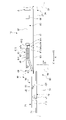
本実施形態の開閉装置1は、いわゆる引き違い窓であり、図1に示すように、枠体20と、枠体20内に開閉可能に嵌め込まれた内障子30(戸体)及び外障子40と、安全装置10と、を備える。開閉装置1は、内障子30及び外障子40の左右方向Xへの開閉移動により開口部20aを開閉可能である。安全装置10は、開閉装置1用である。
枠体20は、上枠21、下枠22および左右の縦枠23,24により矩形に枠組みされている。
上枠21は、長尺状に形成され、枠体20の上部において見付方向に延びる。上枠21は、下方に向けて開放して形成される。下枠22は、長尺状に形成され、枠体20の下部において見付方向に延びる。下枠22は、上方に向けて開放して形成される。
左右の縦枠23,24は、上枠21及び下枠22の見付方向の両端部において上下方向に延びる。左右の縦枠23,24は、長尺状に形成され、枠体20の側部を構成する。
内障子30および外障子40は、いずれも引き戸であり、これらを見付方向にスライドさせることで、枠体20の開口部20aが開放又は閉鎖される、いわゆる引き違い窓を構成する。
内障子30は、図1に示すように、いずれも長尺状の上框31、下框32および左右の縦框である召内框33,戸先框34により矩形に枠組みされた框体35と、框体35内に嵌め込まれて固定されたガラス36と、を含んで構成される。
外障子40は、図1に示すように、いずれも長尺状の上框41、下框42および左右の縦框である召外框43,戸先框44により矩形に枠組みされた框体45と、框体45内に嵌め込まれて固定されたガラス46と、を含んで構成される。
安全装置10について説明する。本実施形態においては、開閉装置1において、図1の左右方向を左右方向Xという。開閉装置1の左右方向Xは、内障子30の横方向でもある。開閉装置1の左右方向Xにおける一方側(図1における左側)をX1側といい、左右方向Xにおける他方側(図1における右側)をX2側という。また、上下方向を上下方向Zという。また、内障子30を枠体20のX2側(図1における右側)において閉める方向(X1側からX2側に移動される方向)を第1移動方向D1といい、内障子30を枠体20のX2側(図1の右側)において開ける方向(X2側からX1側に移動される方向)を第2移動方向D2という。
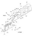
安全装置10は、指挟み防止機構を備えている。安全装置10は、ストッパ装置50と、減速装置80と、を備える。ストッパ装置50は、図1~図4に示すように、ストッパ装置本体60と、操作アーム部70と、を備える。ストッパ装置本体60は、枠体20の上枠21の左右方向XのX2側の端部側に固定されることで、開口部20aの左右方向XのX2側の上部に固定される。操作アーム部70は、内障子30の上框31の左右方向XのX2側に固定されることで、内障子30の左右方向XのX2側の上部に固定される。
操作アーム部70は、図1及び図2に示すように、内障子30が第1移動方向D1に移動されることで、ストッパ装置本体60に導入される。内障子30が第1速度V1よりも速い速度で閉められた場合に、安全装置10が指挟み防止機構を備えているため、内障子30が枠体20の縦枠24に衝突することを防止できる。
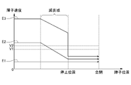
例えば、ストッパ装置50は、内障子30が第1速度V1よりも遅い移動速度で減速装置80に向けて移動された場合に、図5に示す内障子30の動作例E1の動作のように、減速装置80により内障子30の移動速度を減速させない。例えば、ストッパ装置50は、内障子30が第1速度V1以上の移動速度で減速装置80に向けて移動された場合に、図5に示す内障子30の動作例E2、E3のように、内障子30の荷重を受け止めて、減速装置80により内障子30の移動速度を減速させる。
また、例えば、ストッパ装置50は、減速装置80により減速された内障子30が第2速度V2以上の移動速度で移動された場合に、図5に示す内障子30の動作例E3のように、内障子30の開閉動作を一旦停止させる。例えば、ストッパ装置50は、減速装置80により減速された内障子30が第2速度V2よりも遅い移動速度で移動された場合に、図5に示す内障子30の動作例E2のように、内障子30の開閉動作を停止させない。
ストッパ装置本体60は、図2~図4に示すように、ベース部材61と、傾斜ガイド部62と、経路延在板63と、受け止め部64と、ストッパ部66と、を有する。また、ストッパ装置本体60は、操作アーム部70のアーム板72の先端部721が移動する移動経路として、第1移動経路K1(上流側経路)と、落下誘導連通部65(誘導部)と、第2移動経路K2(下流側経路)と、戻り移動経路K3(戻り経路)と、を有する。
ベース部材61は、上面板611と、側面板612と、を有する。上面板611は、見込方向に幅を有して左右方向Xに延びて形成され、上枠21に固定される。側面板612は、上面板611の見込方向の室内側の端部から下方に延びる。
第1移動経路K1は、傾斜ガイド部62の上面側、及び、経路延在板63の上面側を通り、受け止め部64までの経路である。第1移動経路K1は、アーム板72の先端部721(移動部)が受け止め部64に向かう場合に、アーム板72の先端部721が第1移動方向D1に移動されることが可能な経路である。
第2移動経路K2(下流側経路)は、第1移動経路K1の左右方向XのX2側の端部の下部に形成された落下誘導連通部65を介して、第1移動経路K1の左右方向XのX2側の端部の下方に連通して形成され、第1移動経路K1の左右方向XのX2側の端部の下方から、左右方向XのX2側に延びる。第2移動経路K2は、落下誘導連通部65により誘導された操作アーム部70のアーム板72の先端部721が第1移動方向D1に移動されることが可能な経路である。
戻り移動経路K3は、第2移動経路K2における第1移動方向D1側の端部と反対の端部側から第1移動経路K1側に延びて形成され、第1移動経路K1の上流側に合流する経路である。戻り移動経路K3は、左右方向XのX2側からX1側に水平方向に延びており、経路延在板63の下方側、及び、傾斜ガイド部62の下方側を通り、第1移動経路K1の上流側に合流する経路である。
傾斜ガイド部62は、左右方向XのX1側からX2側に向かうに従って下方側から上方側に向かうように傾斜する板状に形成される。傾斜ガイド部62は、左右方向XのX2側の基端が、見込方向に延びる回転軸J3を中心に回転可能に、経路延在板63の左右方向XのX1側の端部に接続される。傾斜ガイド部62は、下方側への回転角度が所定角度で規制された状態で、回転軸J3を中心に回転可能である。
傾斜ガイド部62は、第1移動経路K1と戻り移動経路K3とが合流する部分に配置され、操作アーム部70の先端側ピン73が第1移動経路K1を移動する場合に戻り移動経路K3を閉鎖して第1移動経路K1を形成し、先端側ピン73が戻り移動経路K3から第1移動経路K1に移動する場合に、先端側ピン73が下方から押し上げることで閉位置から回転軸J3を中心に上方側に回転して、先端側ピン73が戻り移動経路K3から第1移動経路K1へ移動する経路を開放する。これにより、傾斜ガイド部62は、アーム板72が戻り移動経路K3を戻る際に、戻り移動経路K3の左右方向XのX1側が開閉されることで、戻り移動経路K3を開閉する開閉部として機能する。
経路延在板63は、傾斜ガイド部62の左右方向XのX2側の端部からX2側に延びる平面板状に形成される。経路延在板63の見込方向の室外側の端部は、傾斜ガイド部62の見込方向の室外側の端部と同じ位置に位置する。
受け止め部64は、第1移動経路K1の左右方向XのX2側の端部に配置される。受け止め部64の左右方向XのX2側の面には、減速装置80が接続されている。
受け止め部64は、内障子30が第1速度V1以上の移動速度で移動された場合に、アーム板72の先端部721の荷重を受け止めて、内障子30の移動速度を減速装置80により減速させる。内障子30が第1速度V1よりも遅い速度で移動された場合には、アーム板72の先端部721は、受け止め部64の手前において、受け止め部64に接触せずに又は接触して、先端側ピン73が第2移動経路K2に連通する落下誘導連通部65(誘導部)により誘導されることで、落下誘導連通部65(誘導部)により、下方(交差方向)に誘導される。
受け止め部64は、上下方向Z及び見込方向に延びる板状の衝突板641と、規制部642と、を有する。
衝突板641は、ベース部材61の上面板611の下方において、ベース部材61に固定される。衝突板641は、見込方向に延びる板状に形成される。衝突板641の見込方向の幅は、傾斜ガイド部62の見込方向の幅よりも長く形成され、傾斜ガイド部62よりも室外側まで延びる。
衝突板641は、左右方向XのX1側を向く衝突面を有する。衝突板641におけるアーム板72の先端部721が衝突する部分は、衝突部641aを構成する。衝突部641aは、受け止め部64の衝突部641aにアーム板72の先端部721が衝突した場合に、受け止め部64の衝突部641aにおけるアーム板72の先端部721が衝突した際の荷重が作用する部分である。
規制部642は、衝突板641の手前側の上部に設けられる。本実施形態においては、規制部642は、ベース部材61の上面板611の下面により構成される。規制部642は、先端側ピン73が上方側へ移動されることを規制することで、アーム板72の先端部721が上方側へ移動することを規制する。
衝突板641の左右方向XのX1側の手前の下部には、第2移動経路K2に連通する落下誘導連通部65(誘導部)が形成されている。落下誘導連通部65は、衝突板641の下端部と経路延在板63の左右方向のX2側の端部との間の隙間により構成される。
落下誘導連通部65は、内障子30が第1速度V1よりも遅い速度で移動された場合に、内障子30が停止せずに、受け止め部64の手前において、先端側ピン73を下方に誘導することで、アーム板72の先端部721を下方(交差方向)に誘導する。内障子30が停止せずに閉められる第1速度V1よりも遅い速度とは、例えば、内障子30を閉める際に内障子30が勢いよく閉まる速度よりも遅い速度を意味する。
内障子30が第1速度V1以上の速度で移動された場合には、受け止め部64により受け止められたアーム板72の先端部721が減速装置80(後述)により減速されることで、内障子30の速度が減速される。内障子30が第1速度V1以上の速度で移動されて受け止め部64により受け止められたアーム板72の先端部721の速度は、内障子30の第1移動方向D1の移動距離に応じて、減速装置80により、第1速度V1以上の速度から徐々に減速される。
落下誘導連通部65は、減速装置80により減速されたアーム板72の先端部721が第2速度V2以上の移動速度で移動された場合に、アーム板72の先端部721が受け止め部64に受け止めれた後にアーム板72の先端部721を下方(交差方向)に誘導し、内障子30が第2速度V2よりも遅い速度で移動された場合に、内障子30の開閉動作を停止させずに受け止め部64の手前においてアーム板72の先端部721を下方(交差方向)に誘導する。
落下誘導連通部65の隙間の左右方向Xの長さLは、先端側ピン73が通過可能な長さであって、内障子30が第1速度V1以上又は第2速度V2以上の速度で第1移動方向D1に移動して先端側ピン73がストッパ装置本体60に導入された場合に、先端側ピン73が、落下誘導連通部65の隙間から落下する前に、アーム板72の先端部721が衝突板641に衝突することが可能な長さに設定できる。
減速装置80は、受け止め部64の左右方向XのX2側の面に接続される。減速装置80は、受け止め部64により受け止められたアーム板72の先端部721の移動速度を減速させることで、内障子30の開閉移動の移動速度を減速させる。減速装置80は、減速装置本体81と、左右方向Xに延びるピストン82と、を有する。減速装置本体81は、内部にオイルダンパー機構(図示せず)を有する。減速装置本体81のオイルダンパー機構は、ピストン82が左右方向Xに進退した場合に、内部に収容される作動オイルの抵抗によりピストン82に作用する力を減衰させる。
ピストン82の左右方向XのX1側の端部は、受け止め部64の左右方向XのX2側の面に接続されている。ピストン82の左右方向XのX2側の端部側は、減速装置本体81に支持されている。ピストン82は、減速装置本体81に対して左右方向Zに進退可能である。
減速装置本体81の左右方向XのX1側の端部には、ストッパ装置本体60のストッパ部66が設けられている。ストッパ部66は、減速装置80により減速されたアーム板72の先端部721が受け止め部64に受け止められた状態で所定位置まで移動された場合に、内障子30の開閉動作を一旦停止させるように受け止め部64の移動を規制する。
ストッパ部66は、受け止め部64が、減速装置80のピストン82が進退して最も減速装置80側に移動した場合に、受け止め部64の左右方向のX2側の面が衝突する。ストッパ部66は、受け止め部64がストッパ部66に衝突した場合に、内障子30と枠体20の縦枠24との間に、指挟みを防止できる距離を空けることができる位置に配置される。これにより、アーム板72の先端部721を受け止めた受け止め部64の左右方向Xの移動がストッパ部66により規制されるため、内障子30が枠体20の縦枠24に衝突することを防止できる。
以上のように、受け止め部64の左右方向XのX2側には、減速装置80が接続されている。そのため、操作アーム部70のアーム板72の先端部721が受け止め部64の衝突板641の衝突部641aに受け止められた状態で、内障子30は、減速装置80により減速される。
そして、内障子30が減速装置80により減速されている状態において、受け止め部64がストッパ部66に到達する前に、内障子30が第2速度V2よりも遅い速度に減速された場合には、落下誘導連通部65は、内障子30の開閉動作を停止させずに受け止め部64の手前においてアーム板72の先端部721を下方(交差方向)に誘導する。
また、内障子30が減速装置80により減速されている状態において、受け止め部64がストッパ部66に到達するまで、内障子30が第2速度V2以上の速度である場合には、落下誘導連通部65は、受け止め部64がストッパ部66に衝突して内障子30の開閉動作を一旦停止させた後に先端側ピン73を下方に誘導することで、アーム板72の先端部721を下方(交差方向)に誘導する。
減速装置80により減速された内障子30が一旦停止する第2速度V2以上は、仮に減速装置80において内障子30が減速されていない場合に、内障子30が勢いよく閉まる速度以上を意味する。本実施形態においては、減速装置80おいて内障子30が減速されても第2速度V2以上の速度である場合には、受け止め部64がストッパ部66に衝突することで、内障子30が枠体20の縦枠24に勢いよく衝突することが抑制されて、内障子30は一旦停止する。
一方、減速装置80により減速された内障子30が停止せずに閉められる第2速度V2よりも遅い速度とは、例えば、内障子30を閉める際に内障子30が勢いよく閉まる速度よりも遅い速度を意味する。
操作アーム部70は、図1に示すように、内障子30の上框31の左右方向XのX2側に配置される。操作アーム部70は、内障子30が左右方向XのX2側において閉まる側に移動された場合に、ストッパ装置本体60に導入される。操作アーム部70は、図2~図4に示すように、操作側ベース部材71と、アーム板72(アーム部材)と、先端側ピン73(ガイド部)と、を有する。
操作側ベース部材71は、図2~図4に示すように、左右方向Xに延びて形成される。操作側ベース部材71は、傾斜ガイド部62よりも室外側にずれた位置に配置され、内障子30が左右方向Xに移動されることで、ストッパ装置本体60の傾斜ガイド部62に沿って左右方向Xに移動する。
操作側ベース部材71は、下面板711と、第1側面板712と、第2側面板713と、を有する。下面板711は、見込方向に幅を有して左右方向Xに延びて形成される。下面板711は、見込方向に幅を有して左右方向Xに延びて形成される。
第1側面板712は、下面板711の見込方向の室内側の端部から上方に立ち上がる。第2側面板713は、下面板711の見込方向の室外側の端部から上方に立ち上がる。
アーム板72は、長尺の板状に形成され、操作側ベース部材71に取り付けられる。アーム板72は、傾斜ガイド部62よりも室外側にずれた位置において操作側ベース部材71に取り付けられ、内障子30が左右方向Xに移動されることで、ストッパ装置本体60の傾斜ガイド部62に沿って左右方向Xに移動する。アーム板72は、操作アーム部70がストッパ装置本体60に導入される前の状態において、左右方向Xに延びる。
アーム板72は、回転軸J1を中心に回転可能に構成される。回転軸J1は、図2に示すように、回転軸J1方向に見た場合に、受け止め部64の衝突板641の衝突部641aよりも下方に配置される。衝突部641aは、アーム板72の先端部721が衝突する部分であり、受け止め部64の衝突板641において、アーム板72の先端部721が衝突した際の荷重が作用する部分である。
アーム板72の基端側は、回転軸J1を中心に回転可能に操作側ベース部材71の左右方向のX1側に接続される。アーム板72の先端には、先端部721(移動部)が形成される。先端部721は、円弧状に形成される。アーム板72の先端側には、見込方向の室内側に突出する先端側ピン73が設けられている。
先端側ピン73は、ピン状に形成され、アーム板72の先端側において、アーム板72の室内側の面から室内側に突出する。先端側ピン73は、見込方向に見た場合に、アーム板72の先端部721よりもアーム板72の内部側の基端側に配置される。先端側ピン73は、見込方向に延びる中心軸J2を中心に回転可能である。
先端側ピン73は、アーム板72の先端側に設けられており、操作アーム部70が第1移動方向D1に移動した場合に、アーム板72が回転軸J1を中心に回転するため、傾斜ガイド部62の上面に沿って移動される。これにより、先端側ピン73は、アーム板72の先端部721の移動をガイドする。先端側ピン73は、アーム板72の先端部721を、内障子30が移動する第1移動方向D1及び内障子30の上下方向Z(第1移動方向D1に交差する交差方向)に移動させるようにガイドする。
アーム板72の先端部721は、先端側ピン73が傾斜ガイド部62の上面に沿ってガイドされることで、内障子30の開閉移動に伴って内障子30が移動する第1移動方向D1に移動可能に構成される。アーム板72の先端部721は、アーム板72の回転軸J1を中心に円弧を描きながら上下方向に移動可能に構成される。
これにより、アーム板72の先端部721は、内障子30の開閉移動に伴って内障子30が移動する第1移動方向D1に移動可能に構成されると共に、内障子30の上下方向Z(第1移動方向D1に交差する交差方向)に移動可能である。アーム板72の先端部721は、先端側ピン73が落下誘導連通部65により下方に誘導される場合に、アーム板72の先端部721の自重により下方に誘導される。
次に、本実施形態の開閉装置1の安全装置10の動作について説明する。まず、図6~図8に示すように、内障子30を開位置から第1移動方向D1に移動させて、内障子30を閉める場合について説明する。
内障子30が第1速度V1よりも遅い速度で閉められた場合について説明する。図5に示す内障子30の動作例E1のように、内障子30が第1速度V1よりも遅い速度で閉められた場合には、図6に示すように、内障子30に取り付けられた操作アーム部70は、ストッパ装置本体60に向けて第1移動方向D1に移動される。これにより、図6の上段の図に示すように、ストッパ装置本体60に導入された操作アーム部70のアーム板72の先端部721は、先端側ピン73が傾斜ガイド部62にガイドされることで、第1移動経路K1において傾斜ガイド部62の上面に沿って移動する。
そして、内障子30が第1速度V1よりも遅い速度で閉められているため、図6の中段の図に示すように、操作アーム部70のアーム板72の先端部721は、受け止め部64の衝突板641の衝突部641aに接触せずに又は接触して、落下誘導連通部65を通して、図6の下段の図に示すように、下方側の第2移動経路K2に落下して、内障子30は、停止せずに第1移動方向D1に移動される。これにより、内障子30は、第1移動方向D1に移動されて、閉められる。内障子30が停止せずに閉められる第1速度V1よりも遅い速度とは、例えば、内障子30を閉める際に内障子30が勢いよく閉まる速度よりも遅い速度を意味する。
次に、内障子30が第1速度V1以上の速度で閉められた場合について説明する。図5に示す内障子30の動作例E2、E3のように、内障子30が第1速度V1以上で閉められた場合には、図7に示すように、ストッパ装置本体60に導入された操作アーム部70のアーム板72の先端部721は、先端側ピン73が傾斜ガイド部62にガイドされることで、第1移動経路K1において傾斜ガイド部62の上面に沿って移動し、図7の上段の図に示すように、受け止め部64の衝突板641の衝突部641aに受け止められる。そして、操作アーム部70のアーム板72の先端部721は、受け止め部64の衝突板641の衝突部641aに受け止められた状態で、受け止め部64を押圧しながら左右方向XのX2側に移動する。
受け止め部64の左右方向XのX2側には、減速装置80が接続されている。そのため、操作アーム部70のアーム板72の先端部721が受け止め部64の衝突板641の衝突部641aに受け止められた状態で、内障子30は、減速装置80により減速される。
そして、内障子30が減速装置80により減速されている状態において、図5に示す内障子30の動作例E2のように、受け止め部64がストッパ部66に到達する前に、内障子30が第2速度V2よりも遅い速度に減速された場合には、図7の中段の図及び下段の図に示すように、落下誘導連通部65を通して、下方側の第2移動経路K2に落下して、内障子30は、停止せずに第1移動方向D1に移動される。これにより、内障子30は、第1移動方向D1に移動されて、閉められる。減速装置80により減速された内障子30が停止せずに閉められる第2速度V2よりも遅い速度とは、例えば、内障子30を閉める際に内障子30が勢いよく閉まる速度よりも遅い速度を意味する。
また、内障子30が減速装置80により減速されている状態において、図5に示す内障子30の動作例E3のように、受け止め部64がストッパ部66に到達するまで、内障子30が第2速度V2以上の速度である場合には、図8の上段の図に示すように、受け止め部64は、ストッパ部66に衝突する。
減速装置80により減速された内障子30が一旦停止する第2速度V2以上は、仮に減速装置80において内障子30が減速されていない場合に、内障子30が勢いよく閉まる速度以上を意味する。本実施形態においては、減速装置80おいて内障子30が減速されても第2速度V2以上の速度である場合には、受け止め部64がストッパ部66に衝突することで、内障子30が枠体20の縦枠24に勢いよく衝突することが抑制されて、内障子30は一旦停止する。
ここで、図8の上段の図に示すように、アーム板72の先端部721は、アーム板72の基端の回転軸J1が受け止め部64の衝突板641の衝突部641aよりも下方に配置されている。そのため、第1移動経路K1の左右方向XのX2側の端部に移動されて、受け止め部64がストッパ部66に衝突して、アーム板72の先端部721が受け止め部64に受け止められた場合に、アーム板72の先端部721が受け止め部64に受け止められた状態で斜め上方側に荷重が作用する。また、衝突板641の手前側の上部に設けられる規制部642により、先端側ピン73は、上方側へ移動することが規制される。これにより、アーム板72の先端部721は、下方側に落ちにくい。よって、アーム板72の先端部721が受け止め部64に衝突した状態が保持されやすく、内障子30を一旦停止させやすい。
その後、アーム板72の先端部721は、受け止め部64に衝突した状態で斜め上方側に作用する荷重が緩むことで、自重によりアーム板72の基端の回転軸J1を中心に回転して、落下誘導連通部65を通して、下方側の第2移動経路K2に落下することで、図8の下段の図に示すように、下方側の第2移動経路K2に誘導される。アーム板72の先端部721は、落下誘導連通部65により下方に誘導される場合に、アーム板72の先端部721の自重により下方に誘導される。
次に、図9の上段に示す内障子30の閉位置から、左右方向XのX1側の第2移動方向D2に移動させて、内障子30を開ける場合について説明する。
内障子30を開ける場合には、図9の上段に示す内障子30の閉位置から、内障子30を第2移動方向D2に移動させることで、操作アーム部70は、第2移動経路K2において、第2移動方向D2に移動され、戻り移動経路K3に導入される。
戻り移動経路K3に導入された操作アーム部70が戻り移動経路K3から第1移動経路K1に移動する場合に、図9の下段の図に示すように、アーム板72の先端に設けられた先端側ピン73は、傾斜ガイド部62を下方側から押し上げる。これにより、先端側ピン73は、回転軸J3を中心に傾斜ガイド部62を回転させて、戻り移動経路K3から第1移動経路K1へ移動する経路を開放する。このようにして、内障子30を第2移動方向D2に移動させて、内障子30を開けることができる。
本実施形態によれば、以下の効果が奏される。本実施形態の開閉装置1用の安全装置10は、内障子30の開閉移動により開口部20aを開閉可能な開閉装置1用の安全装置10であって、内障子30の開閉移動の移動速度を減速させる減速装置80と、減速装置80により減速された内障子30の開閉動作を一旦停止させるストッパ装置50と、を備える。そのため、減速装置80とストッパ装置50とを組み合わせた安全装置10とすることで、内障子30が大型化しても、減速装置80の減速機構を大型化しなくても、現状の減速装置80の減速機構で対応できる。これにより、新たな投資が不要となり、コストを低減できる。よって、開閉装置1用の安全装置10を、コストを低減しつつ、小型化できる。
本実施形態においては、ストッパ装置50は、内障子30が第1速度V1以上の移動速度で減速装置80に向けて移動された場合に、内障子30の荷重を受け止めて減速装置80により内障子30の移動速度を減速させ、内障子30が第1速度V1よりも遅い移動速度で減速装置80に向けて移動された場合に、減速装置80により内障子30の移動速度を減速させない。これにより、内障子30が第1速度V1よりも遅い通常の安全な速度で移動される場合には、減速装置80の減速機構を介さずに、内障子30を安定して開閉できる。減速装置80の減速機構を介さずに、内障子30を安定して開閉できるため、余計な操作力を必要とせず、利便性を向上できる。
本実施形態においては、ストッパ装置は、減速装置80により減速された内障子30が第2速度V2以上の移動速度で移動された場合に、内障子30の開閉動作を一旦停止させ、減速装置80により減速された内障子30が第2速度V2よりも遅い移動速度で移動された場合に、内障子30の開閉動作を停止させない。これにより、減速装置80により減速された内障子30の移動速度に応じて、内障子30の開閉動作を一旦停止させることができるため、指挟み防止機構を実現できる。よって、内障子30が大型化しても、減速装置80により減速された後において、内障子30の移動速度が大きい場合に、内障子30の開閉動作を一旦停止させることができるため、安全性が向上する。
以上、本開示の好ましい実施形態について説明したが、本開示は、上述の実施形態に制限されるものではなく、適宜変更が可能である。
例えば、前記実施形態においては、内障子30を閉める場合について説明したが、これに限定されない。例えば、安全装置10のアーム板72を内障子30の戸元側に設けると共に、安全装置10のストッパ装置本体60及び減速装置80を枠体20の上枠21の左右方向のX1側の端部側に設けることで、枠体20の左右方向のX1側において内障子30を開ける場合に用いる安全装置としてもよい。
前記実施形態においては、戸体を内障子30で構成したが、これに限定されず、戸体を、框体及びガラスを有していない扉で構成してもよい。また、例えば、戸体を、ドアで構成してもよい。
自動ドアなどの電動で開閉する扉に適用することで、電動部分が故障して手動で扉を開閉する場合にも、本開示の開閉装置を使用可能である。また、減速装置80を、開閉時に緩やかに閉まるソフトクローズの開閉装置にも適用することができる。
前記実施形態においては、開閉装置1を、引き違い窓で構成したが、これに限定されず、例えば、片引き窓で構成してもよい。
前記実施形態において、ストッパ装置本体60及び減速装置80を上枠21の左右方向XのX2側の端部側に配置し、操作アーム部70を内障子30の左右方向XのX2側に配置したが、これに限定されない。例えば、ストッパ装置本体60及び減速装置80を上枠21の左右方向Xの中央側に配置し、操作アーム部70を内障子30の左右方向Xにおけるストッパ装置本体60及び減速装置80に対応した位置(例えば、内障子30の左右方向Xの中央側)に配置してもよい。
前記実施形態においては、指を挟まない位置で内障子(戸体)を一旦停止させるように、ストッパ装置本体60を取り付けたが、これに限定されない。ストッパ部の左右方向の取付位置を調整することで、内障子を一旦停止させる位置を調整できる。これにより、内障子を一旦停止させる位置を、指よりも大きな頭や胴体を挟まない位置となるように、ストッパ部の左右方向の取付位置を調整することで、指が挟まれることを防止できるだけではなく、頭や胴体が挟まれることも防止できる。
また、ストッパ装置本体60を複数箇所に設ける他の形態として、例えば、3枚建てや4枚建ての引き違いの引戸同士の間にストッパ装置本体60を取り付けることで、引戸同士の間での指挟みを防止してもよい。
前記実施形態においては、先端側ピン73を、中心軸を回転軸として回転可能に構成したが、これに限定されず、先端側ピン73は、回転しない構成でもよい。
前記実施形態においては、アーム板72の先端部721を受け止め部64に衝突させるように構成したが、これに限定されない。アーム板72の先端にローラを設けて、アーム板の先端に設けたローラをストッパ部に衝突させるように構成してもよい。この場合、アーム板72の先端に設けたローラを、アーム板72の移動をガイドするピンとして構成してもよい。
1 開閉装置、10 安全装置、20a 開口部、30 内障子(戸体)、50 ストッパ装置、80 減速装置、D1 第1移動方向
Claims (3)
- 戸体の開閉移動により開口部を開閉可能な開閉装置用の安全装置であって、
前記戸体の開閉移動の移動速度を減速させる減速装置と、
前記減速装置により減速された前記戸体の開閉動作を一旦停止させるストッパ装置と、を備える開閉装置用の安全装置。 - 前記ストッパ装置は、前記戸体が第1速度以上の移動速度で前記減速装置に向けて移動された場合に、前記戸体の荷重を受け止めて前記減速装置により前記戸体の移動速度を減速させ、前記戸体が第1速度よりも遅い移動速度で前記減速装置に向けて移動された場合に、前記減速装置により前記戸体の移動速度を減速させない、請求項1に記載の開閉装置用の安全装置。
- 前記ストッパ装置は、前記減速装置により減速された前記戸体が第2速度以上の移動速度で移動された場合に、前記戸体の開閉動作を一旦停止させ、前記減速装置により減速された前記戸体が前記第2速度よりも遅い移動速度で移動された場合に、前記戸体の開閉動作を停止させない、請求項1又は2に記載の開閉装置用の安全装置。
Applications Claiming Priority (2)
| Application Number | Priority Date | Filing Date | Title |
|---|---|---|---|
| JP2020219033A JP2022104049A (ja) | 2020-12-28 | 2020-12-28 | 開閉装置用の安全装置 |
| JP2020-219033 | 2020-12-28 |
Publications (1)
| Publication Number | Publication Date |
|---|---|
| WO2022145221A1 true WO2022145221A1 (ja) | 2022-07-07 |
Family
ID=82260674
Family Applications (1)
| Application Number | Title | Priority Date | Filing Date |
|---|---|---|---|
| PCT/JP2021/046041 Ceased WO2022145221A1 (ja) | 2020-12-28 | 2021-12-14 | 開閉装置用の安全装置 |
Country Status (2)
| Country | Link |
|---|---|
| JP (2) | JP2022104049A (ja) |
| WO (1) | WO2022145221A1 (ja) |
Citations (3)
| Publication number | Priority date | Publication date | Assignee | Title |
|---|---|---|---|---|
| JP3019137U (ja) * | 1995-06-09 | 1995-12-12 | 株式会社桂 | 扉の指詰め防止具 |
| US20020157319A1 (en) * | 2001-04-27 | 2002-10-31 | Ataul Haq | Door slam child finger safety mechanism |
| JP2005171545A (ja) * | 2003-12-09 | 2005-06-30 | Hitoshi Nishitani | 引戸用制動装置 |
Family Cites Families (2)
| Publication number | Priority date | Publication date | Assignee | Title |
|---|---|---|---|---|
| JP5067002B2 (ja) | 2007-05-08 | 2012-11-07 | アイシン精機株式会社 | スライド式開閉体の挟み込み防止装置 |
| JP5385238B2 (ja) | 2010-09-29 | 2014-01-08 | Ykk Ap株式会社 | 建具 |
-
2020
- 2020-12-28 JP JP2020219033A patent/JP2022104049A/ja active Pending
-
2021
- 2021-12-14 WO PCT/JP2021/046041 patent/WO2022145221A1/ja not_active Ceased
-
2024
- 2024-02-07 JP JP2024017060A patent/JP7710062B2/ja active Active
Patent Citations (3)
| Publication number | Priority date | Publication date | Assignee | Title |
|---|---|---|---|---|
| JP3019137U (ja) * | 1995-06-09 | 1995-12-12 | 株式会社桂 | 扉の指詰め防止具 |
| US20020157319A1 (en) * | 2001-04-27 | 2002-10-31 | Ataul Haq | Door slam child finger safety mechanism |
| JP2005171545A (ja) * | 2003-12-09 | 2005-06-30 | Hitoshi Nishitani | 引戸用制動装置 |
Also Published As
| Publication number | Publication date |
|---|---|
| JP2024036599A (ja) | 2024-03-15 |
| JP2022104049A (ja) | 2022-07-08 |
| JP7710062B2 (ja) | 2025-07-17 |
Similar Documents
| Publication | Publication Date | Title |
|---|---|---|
| KR20140018838A (ko) | 발 작동식 도어 개폐기 | |
| WO2022145221A1 (ja) | 開閉装置用の安全装置 | |
| AU2017360021A1 (en) | Door driving mechanism for a swing door | |
| CN1853025A (zh) | 带有阻滞装置的改进的枢转窗户 | |
| KR101410775B1 (ko) | 자연 환기창 | |
| WO2021075185A1 (ja) | 開閉装置 | |
| KR102246409B1 (ko) | 양쪽 손 끼임 방지 도어 | |
| JP2022104047A (ja) | 開閉装置用の安全装置 | |
| WO2022145220A1 (ja) | 開閉装置用の安全装置の取付構造 | |
| KR102519537B1 (ko) | 슬라이딩 창호용 댐퍼조립체 | |
| US6000503A (en) | Sliding two speed door mechanism for an elevator car | |
| JP7735491B1 (ja) | エレベータドア装置 | |
| KR102112601B1 (ko) | 자동 게이트 | |
| JP2023137539A (ja) | 開閉装置用の安全装置 | |
| JP2021088897A (ja) | 開閉装置用の安全装置 | |
| JP2541757B2 (ja) | 減速装置付引戸 | |
| CN211573086U (zh) | 一种平衡门的控速结构 | |
| CN214740600U (zh) | 闸门自锁装置及保险柜 | |
| KR101280609B1 (ko) | 창문 개폐용 아암 조립체 | |
| JP2004316094A (ja) | 扉の安全開閉構造 | |
| JP2005083182A (ja) | 扉の扉開閉装置 | |
| JP3921145B2 (ja) | 扉装置 | |
| KR102070134B1 (ko) | 반 자동문 시스템 | |
| JP4731061B2 (ja) | シャッター収納ケースの開閉装置 | |
| JP2024101446A (ja) | 開閉装置用の安全装置の取付構造 |
Legal Events
| Date | Code | Title | Description |
|---|---|---|---|
| 121 | Ep: the epo has been informed by wipo that ep was designated in this application |
Ref document number: 21915082 Country of ref document: EP Kind code of ref document: A1 |
|
| NENP | Non-entry into the national phase |
Ref country code: DE |
|
| 122 | Ep: pct application non-entry in european phase |
Ref document number: 21915082 Country of ref document: EP Kind code of ref document: A1 |