WO2022145201A1 - バドミントンラケット - Google Patents
バドミントンラケット Download PDFInfo
- Publication number
- WO2022145201A1 WO2022145201A1 PCT/JP2021/045544 JP2021045544W WO2022145201A1 WO 2022145201 A1 WO2022145201 A1 WO 2022145201A1 JP 2021045544 W JP2021045544 W JP 2021045544W WO 2022145201 A1 WO2022145201 A1 WO 2022145201A1
- Authority
- WO
- WIPO (PCT)
- Prior art keywords
- sheet
- racket
- shaft
- fiber
- reinforcing layer
- Prior art date
- Legal status (The legal status is an assumption and is not a legal conclusion. Google has not performed a legal analysis and makes no representation as to the accuracy of the status listed.)
- Ceased
Links
Images








Classifications
-
- A—HUMAN NECESSITIES
- A63—SPORTS; GAMES; AMUSEMENTS
- A63B—APPARATUS FOR PHYSICAL TRAINING, GYMNASTICS, SWIMMING, CLIMBING, OR FENCING; BALL GAMES; TRAINING EQUIPMENT
- A63B49/00—Stringed rackets, e.g. for tennis
-
- A—HUMAN NECESSITIES
- A63—SPORTS; GAMES; AMUSEMENTS
- A63B—APPARATUS FOR PHYSICAL TRAINING, GYMNASTICS, SWIMMING, CLIMBING, OR FENCING; BALL GAMES; TRAINING EQUIPMENT
- A63B2102/00—Application of clubs, bats, rackets or the like to the sporting activity ; particular sports involving the use of balls and clubs, bats, rackets, or the like
- A63B2102/04—Badminton
-
- Y—GENERAL TAGGING OF NEW TECHNOLOGICAL DEVELOPMENTS; GENERAL TAGGING OF CROSS-SECTIONAL TECHNOLOGIES SPANNING OVER SEVERAL SECTIONS OF THE IPC; TECHNICAL SUBJECTS COVERED BY FORMER USPC CROSS-REFERENCE ART COLLECTIONS [XRACs] AND DIGESTS
- Y02—TECHNOLOGIES OR APPLICATIONS FOR MITIGATION OR ADAPTATION AGAINST CLIMATE CHANGE
- Y02T—CLIMATE CHANGE MITIGATION TECHNOLOGIES RELATED TO TRANSPORTATION
- Y02T90/00—Enabling technologies or technologies with a potential or indirect contribution to GHG emissions mitigation
Definitions
- the badminton racket has a frame, string and shaft.
- the frame has a top and a bottom.
- the strings form a face.
- the player shoots the shuttle with a racket.
- the shot causes the face to collide with the shuttle.
- the impact of the collision is transmitted from the string through the frame to the shaft.
- the shot deforms the frame and shaft.
- a typical RBI in smash is closer to the bottom and a typical RBI in lobing is closer to the top.
- a typical hit point in a drive is near the center.
- the shuttle In the drive, the shuttle flies at high speed and almost horizontally.
- the drive causes the opponent player to lose his or her posture. From the point of view of winning the game, driving is an important shot.
- the shuttle In the drive, the shuttle needs to fly at a height that exceeds the net. Players need the skill to fly the shuttle at the intended height. Drive-heavy players want a stable trajectory for the shuttle.
- driven clear involves a cut action. Therefore, in driven clear, the shuttle rotates. This rotation slows the shuttle. This deceleration causes the opponent player to lose his or her posture. From the point of view of winning the game, driven clear is an important shot.
- driven clear the shuttle needs to fly at a height that exceeds the net. Driven clear also requires the shuttle to fly as low as the opponent's court. Players need the skill to fly the shuttle at the intended height. Players who make heavy use of driven clears want a stable trajectory for the shuttle.
- the intention of the applicant is to provide a badminton racket that can suppress the variation in the trajectory of the shuttle in a shot where the hitting point is near the center.
- a preferred badminton racket is Shafts with bad ends and tip ends, A grip on which the vicinity of the bad end of the shaft is inserted, It also has a frame attached to the shaft in the vicinity of the chip end.
- This racket is ... Satisfy the following formula (1.1) or (1.2).
- y ⁇ x + 5.0 (1.1) y ⁇ x --5.0 (1.2) Y in these mathematical formulas (1.1) and (1.2) is calculated by the following mathematical formula (1.3).
- y ( ⁇ o1 * ⁇ o2) 1/2 (1.3)
- X in these mathematical formulas (1.1) and (1.2) is calculated by the following mathematical formula (1.4).
- ⁇ o1 represents the out-of-plane primary natural frequency (Hz) in the natural vibration of the racket under the free constraint condition
- ⁇ o2 is the out-of-plane second in the natural vibration of the racket under the free constraint condition. Represents the next natural frequency (Hz).
- EI1 represents the cantilever rigidity (N / mm) of the racket
- EI2 represents the ball striking rigidity (N / mm) of the racket.
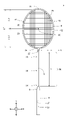
- FIG. 1 is a front view showing a badminton racket according to an embodiment.
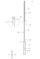
- FIG. 2 is a right side view showing the racket of FIG.
- FIG. 3 is an enlarged cross-sectional view showing a part of the shaft of the racket of FIG.
- FIG. 4 is an enlarged cross-sectional view taken along the line IV-IV of FIG.
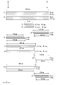
- FIG. 5 is a developed view showing a prepreg for the shaft of the racket of FIG.
- FIG. 6 is an explanatory diagram showing a method of measuring the frequency of the out-of-plane natural vibration of the racket of FIG.
- FIG. 7 is a graph showing the results obtained by the measurement of FIG. FIG.
- FIG. 8A is a plan view showing a method of measuring the cantilever rigidity of the racket of FIG. 1 in the out-of-plane direction
- FIG. 8B is a front view thereof
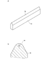
- 9A is a perspective view showing an indenter used in the measuring method of FIG. 8, and FIG. 9B is an enlarged sectional view thereof
- 10A is a plan view showing a method of measuring the ball striking rigidity EI2 of the racket of FIG. 1, and FIG. 10B is a front view thereof.
- 11A is a perspective view showing the first bar used in the measurement method of FIG. 10, and FIG. 11B is an enlarged sectional view thereof.
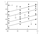
- FIG. 12 is a graph showing the relationship between the value x and the value y of the badminton racket of FIG.
- FIG. 13 is a developed view showing a prepreg for a racket shaft according to another embodiment.
- FIG. 14 is an explanatory diagram showing a method for measuring the frequency of in-plane natural vibration of a racket having a shaft obtained from the prepreg of FIG.
- 17A is a plan view showing a method of measuring the lateral pressure rigidity of the racket of FIG.
- FIG. 17B is a front view thereof.
- FIG. 18 is a graph showing the relationship between the value x and the value y of the badminton racket of FIG.
- FIG. 19 is a front view showing the badminton racket according to the first to fifth embodiment of the present invention.
- FIG. 20 is a front view showing a badminton racket according to Example 1-12 of the present invention.
- FIG. 21 is a front view showing a badminton racket according to Example 1-9 of the present invention.
- FIG. 22 is a front view showing a badminton racket according to Example 2-4 of the present invention.
- FIGS. 1 and 2 Badminton racket 2 is shown in FIGS. 1 and 2.
- the racket 2 has a shaft 4, a frame 6, a neck 8, a cap 9, a grip 10, and a string 12.
- the arrow X represents the width direction
- the arrow Y represents the axial direction
- the arrow Z represents the thickness direction.
- the shaft 4 has a bad portion 14, a middle portion 16, and a tip portion 18.
- the shaft 4 further has a bad end 20 and a tip end 22.
- the shaft 4 is hollow.
- the shaft 4 is made of a fiber reinforced resin. This fiber reinforced resin has a resin matrix and a large number of reinforced fibers.
- the shaft 4 includes a plurality of fiber reinforcing layers (described in detail later).
- thermocurable resins such as epoxy resin, pismareimide resin, polyimide and phenol resin; and polyether ether ketone, polyether sulfone, polyetherimide, polyphenylene sulfide, polyamide and polypropylene.
- Thermoplastic resin is exemplified.
- a resin particularly suitable for the shaft 4 is an epoxy resin.
- Examples of the reinforcing fiber of the shaft 4 include carbon fiber, metal fiber, glass fiber and aramid fiber.
- a fiber particularly suitable for the shaft 4 is carbon fiber. Multiple types of fibers may be used in combination.
- the frame 6 is annular and hollow.
- the frame 6 is made of a fiber reinforced resin.
- a base resin similar to the base resin of the shaft 4 can be used.
- the same reinforcing fibers as the reinforcing fibers of the shaft 4 can be used.
- the frame 6 is tightly coupled to the tip end 22 of the shaft 4 via the neck 8.
- the frame 6 has a top 24 and a bottom 26.
- the grip 10 has a hole 27 extending in the axial direction (Y direction). The vicinity of the bad end 20 of the shaft 4 is inserted into this hole 27. The inner peripheral surface of the hole 27 and the outer peripheral surface of the shaft 4 are joined with an adhesive.
- the string 12 is stretched on the frame 6.
- the string 12 is stretched along the width direction X and the axial direction Y.
- the portion of the string 12 extending along the width direction X is referred to as a lateral thread 28.
- the portion of the string 12 extending along the axial direction Y is referred to as a vertical thread 30.
- the face 32 is formed by the plurality of horizontal threads 28 and the plurality of vertical threads 30.
- the face 32 is generally along the XY plane.
- the arrow Lf represents the length of the face 32.
- the length Lf is measured along the Y direction.
- the reference numeral FC represents the center of the face 32.
- the center FC is the midpoint of the face 32 in the X direction and the midpoint of the face 32 in the Y direction.
- reference numeral 34 represents an exposed portion of the shaft 4.
- the exposed portion 34 is exposed from the neck 8 and is exposed from the grip 10.
- the reference numeral Ls is the length of the exposed portion 34.
- the length Ls is usually 150 mm or more and 210 mm or less.
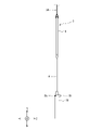
- FIG. 3 is an enlarged cross-sectional view showing a part of the shaft 4 of the racket 2 of FIG.
- FIG. 4 is an enlarged cross-sectional view taken along the line IV-IV of FIG.
- the shaft 4 is hollow.
- the cross-sectional shape of the shaft 4 is a circle. In other words, the shaft 4 has a cylindrical shape.
- the arrow Di represents the inner diameter of the shaft 4.
- a typical inner diameter Di is 3 mm or more and 10 mm or less.
- the arrow Do represents the outer diameter of the shaft 4.
- a typical outer diameter Do is 5 mm or more and 15 mm or less.
- the shaft 4 is made of fiber reinforced resin.
- the shaft 4 can be manufactured by a seat winding method. In this sheet winding method, multiple prepregs are wrapped around a mandrel. Each prepreg has a plurality of fibers and a matrix resin. This matrix resin is not cured.
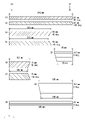
- FIG. 5 is a development view showing a prepreg configuration for the shaft 4 of the racket 2 of FIG.
- This prepreg configuration has 11 prepregs (ie, sheets).
- this prepreg configuration includes a first sheet S1, a second sheet S2, a third sheet S3, a fourth sheet S4, a fifth sheet S5, a sixth sheet S6, a seventh sheet S7, and an eighth sheet S8. It has a ninth sheet S9, a tenth sheet S10, and an eleventh sheet S11. From these prepregs, a plurality of fiber reinforcing layers are formed by the method described later.
- the first fiber reinforcing layer is formed from the first sheet S1
- the second fiber reinforcing layer is formed from the second sheet S2
- the third fiber reinforcing layer is formed from the third sheet S3, and the fourth sheet.
- the fourth fiber reinforcing layer is formed from S4
- the fifth fiber reinforcing layer is formed from the fifth sheet S5
- the sixth fiber reinforcing layer is formed from the sixth sheet S6,
- the seventh fiber reinforcing layer is formed from the seventh sheet S7.
- the eighth sheet S8 forms the eighth fiber reinforcing layer
- the ninth sheet S9 forms the ninth fiber reinforcing layer
- the tenth sheet S10 forms the tenth fiber reinforcing layer
- the eleventh sheet S11 forms.
- the eleventh fiber reinforcing layer is formed from.
- the left-right direction in FIG. 5 is the axial direction of the shaft 4.
- the positions of the bad end 20 and the chip end 22 are indicated by arrows.
- the scale in the left-right direction does not match the scale in the up-down direction.
- the first sheet S1 exists over the entire shaft 4.
- the shape of the first sheet S1 is generally rectangular.
- the first sheet S1 contains a plurality of carbon fibers arranged in parallel.
- the extending direction of each carbon fiber is inclined with respect to the axial direction.
- the angle of the extending direction of the carbon fiber with respect to the axial direction is 30 ° or more and 60 ° or less. In this embodiment, this angle is 45 °.
- the first sheet S1 has a width of 70 mm and a length of 340 mm.
- the second sheet S2 exists over the entire shaft 4.
- the shape of the second sheet S2 is generally rectangular.
- the second sheet S2 contains a plurality of carbon fibers arranged in parallel.
- the extending direction of each carbon fiber is inclined with respect to the axial direction.
- the angle of the extending direction of the carbon fiber with respect to the axial direction is ⁇ 60 ° or more and ⁇ 30 ° or less. In this embodiment, this angle is ⁇ 45 °.
- the second sheet S2 has a width of 70 mm and a length of 340 mm.
- the inclination direction of the carbon fibers in the second sheet S2 is opposite to the inclination direction of the carbon fibers in the first sheet S1. Therefore, the inclination direction of the carbon fibers in the second fiber reinforcing layer is opposite to the inclination direction of the carbon fibers in the first fiber reinforcing layer.
- a bias structure is achieved by the first fiber reinforcing layer and the second fiber reinforcing layer.
- the first fiber reinforcing layer and the second fiber reinforcing layer contribute to the flexural rigidity and the torsional rigidity of the shaft 4.
- the first fiber reinforced layer and the second fiber reinforced layer particularly contribute to the torsional rigidity of the shaft 4.
- the third sheet S3 is biased to the middle portion 16 of the shaft 4.
- the shape of the third sheet S3 is approximately a parallelogram.
- the third sheet S3 contains a plurality of carbon fibers arranged in parallel.
- the extending direction of each carbon fiber is inclined with respect to the axial direction.
- the angle of the extending direction of the carbon fiber with respect to the axial direction is 30 ° or more and 60 ° or less. In this embodiment, this angle is 45 °.
- the third sheet S3 has a width of 15.5 mm and a length of 70 mm.
- the fourth sheet S4 is biased to the middle portion 16 of the shaft 4. In the axial direction, the position of the fourth sheet S4 coincides with the position of the third sheet S3.
- the shape of the fourth sheet S4 is generally a parallelogram.
- the fourth sheet S4 contains a plurality of carbon fibers arranged in parallel. The extending direction of each carbon fiber is inclined with respect to the axial direction. The angle of the extending direction of the carbon fiber with respect to the axial direction is ⁇ 60 ° or more and ⁇ 30 ° or less. In this embodiment, this angle is ⁇ 45 °.
- the fourth sheet S4 has a width of 15.5 mm and a length of 70 mm.
- the inclination direction of the carbon fibers in the fourth sheet S4 is opposite to the inclination direction of the carbon fibers in the third sheet S3. Therefore, the inclination direction of the carbon fibers in the fourth fiber reinforcing layer is opposite to the inclination direction of the carbon fibers in the third fiber reinforcing layer.
- a bias structure is achieved by a third fiber reinforced layer and a fourth fiber reinforced layer.
- the third fiber reinforcing layer and the fourth fiber reinforcing layer contribute to the flexural rigidity and the torsional rigidity of the middle portion 16.
- the third fiber reinforcing layer and the fourth fiber reinforcing layer particularly contribute to the torsional rigidity of the middle portion 16.
- the fifth sheet S5 is biased toward the tip end 22 side of the shaft 4.
- the shape of the fifth sheet S5 is generally trapezoidal.
- the fifth sheet S5 contains a plurality of carbon fibers arranged in parallel.
- the extending direction of each carbon fiber coincides with the axial direction. In other words, the angle of the extending direction of the carbon fiber with respect to the axial direction is substantially 0 °.
- the width is 31 mm
- the length of the upper base is 105 mm
- the length of the lower base is 115 mm.
- the carbon fibers contained in the fifth sheet S5 are substantially oriented in the axial direction. Therefore, even in the fifth fiber reinforcing layer, the carbon fibers are substantially axially oriented.
- a structure in which the carbon fibers are substantially axially oriented is referred to as a "straight structure".
- the fifth fiber reinforcing layer has a straight structure. When the shaft 4 bends, a large tension is applied to these carbon fibers. This tension suppresses further deflection of the shaft 4. In other words, these carbon fibers contribute to the flexural rigidity of the shaft 4.
- the fifth fiber reinforcing layer particularly contributes to the bending rigidity of the tip portion 18.
- the sixth sheet S6 is biased toward the bad end 20 side of the shaft 4.
- the shape of the sixth sheet S6 is generally trapezoidal.
- the sixth sheet S6 contains a plurality of carbon fibers arranged in parallel. The extending direction of each carbon fiber coincides with the axial direction. In other words, the angle of the extending direction of the carbon fiber with respect to the axial direction is substantially 0 °.
- the width is 31 mm
- the length of the upper base is 155 mm
- the length of the lower base is 165 mm.
- the carbon fibers contained in the sixth sheet S6 are substantially oriented in the axial direction. Therefore, even in the sixth fiber reinforcing layer, the carbon fibers are substantially axially oriented.
- the sixth fiber reinforcing layer has a straight structure. When the shaft 4 bends, a large tension is applied to these carbon fibers. This tension suppresses further deflection of the shaft 4. In other words, these carbon fibers contribute to the flexural rigidity of the shaft 4.
- the sixth fiber reinforcing layer particularly contributes to the bending rigidity of the bad portion 14.
- the 7th seat S7 is biased toward the bad end 20 side of the shaft 4.
- the shape of the seventh sheet S7 is generally trapezoidal.
- the seventh sheet S7 contains a plurality of carbon fibers arranged in parallel.
- the extending direction of each carbon fiber is inclined with respect to the axial direction.
- the angle of the extending direction of the carbon fiber with respect to the axial direction is 30 ° or more and 60 ° or less. In this embodiment, this angle is 45 °.
- the width is 38.5 mm
- the length of the upper base is 235 mm
- the length of the lower base is 245 mm.
- the eighth sheet S8 is biased toward the bad end 20 side of the shaft 4. In the axial direction, the position of the eighth sheet S8 coincides with the position of the seventh sheet S7.
- the shape of the eighth sheet S8 is generally trapezoidal.
- the eighth sheet S8 contains a plurality of carbon fibers arranged in parallel. The extending direction of each carbon fiber is inclined with respect to the axial direction. The angle of the extending direction of the carbon fiber with respect to the axial direction is ⁇ 60 ° or more and ⁇ 30 ° or less. In this embodiment, this angle is ⁇ 45 °.
- the width is 38.5 mm
- the length of the upper base is 235 mm
- the length of the lower base is 245 mm.
- the inclination direction of the carbon fibers in the eighth sheet S8 is opposite to the inclination direction of the carbon fibers in the seventh sheet S7. Therefore, the inclination direction of the carbon fibers in the eighth fiber reinforcing layer is opposite to the inclination direction of the carbon fibers in the seventh fiber reinforcing layer.
- a bias structure is achieved by the seventh fiber reinforcing layer and the eighth fiber reinforcing layer.
- the seventh fiber reinforcing layer and the eighth fiber reinforcing layer contribute to the flexural rigidity and the torsional rigidity of the bad portion 14.
- the seventh fiber reinforcing layer and the eighth fiber reinforcing layer particularly contribute to the torsional rigidity of the bad portion 14 and the middle portion 16.
- the ninth sheet S9 is biased toward the tip end 22 side of the shaft 4.
- the shape of the ninth sheet S9 is generally trapezoidal.
- the ninth sheet S9 contains a plurality of carbon fibers arranged in parallel. The extending direction of each carbon fiber coincides with the axial direction. In other words, the angle of the extending direction of the carbon fiber with respect to the axial direction is substantially 0 °.
- the width is 77 mm
- the length of the upper base is 95 mm
- the length of the lower base is 105 mm.
- the carbon fibers contained in the ninth sheet S9 are substantially oriented in the axial direction. Therefore, even in the ninth fiber reinforcing layer, the carbon fibers are substantially axially oriented.
- the ninth fiber reinforcing layer has a straight structure. When the shaft 4 bends, a large tension is applied to these carbon fibers. This tension suppresses further deflection of the shaft 4. In other words, these carbon fibers contribute to the flexural rigidity of the shaft 4.
- the ninth fiber reinforcing layer particularly contributes to the bending rigidity of the tip portion 18.
- the tenth sheet S10 is biased toward the bad end 20 side of the shaft 4.
- the shape of the tenth sheet S10 is generally trapezoidal.
- the tenth sheet S10 contains a plurality of carbon fibers arranged in parallel.
- the extending direction of each carbon fiber coincides with the axial direction. In other words, the angle of the extending direction of the carbon fiber with respect to the axial direction is substantially 0 °.
- the width is 72 mm
- the length of the upper base is 235 mm
- the length of the lower base is 245 mm.
- the carbon fibers contained in the tenth sheet S10 are substantially oriented in the axial direction. Therefore, even in the tenth fiber reinforcing layer, the carbon fibers are substantially axially oriented.
- the tenth fiber reinforcing layer has a straight structure. When the shaft 4 bends, a large tension is applied to these carbon fibers. This tension suppresses further deflection of the shaft 4. In other words, these carbon fibers contribute to the flexural rigidity of the shaft 4.
- the tenth fiber reinforcing layer particularly contributes to the bending rigidity of the bad portion 14 and the middle portion 16.
- the eleventh sheet S11 is biased toward the tip end 22 side of the shaft 4.
- the shape of the eleventh sheet S11 is generally trapezoidal.
- the eleventh sheet S11 contains a plurality of carbon fibers arranged in parallel.
- the extending direction of each carbon fiber coincides with the axial direction. In other words, the angle of the extending direction of the carbon fiber with respect to the axial direction is substantially 0 °.
- the width is 72 mm
- the length of the upper base is 95 mm
- the length of the lower base is 105 mm.
- the carbon fibers contained in the eleventh sheet S11 are substantially oriented in the axial direction. Therefore, even in the eleventh fiber reinforced layer, the carbon fibers are substantially axially oriented.
- the eleventh fiber reinforced layer has a straight structure. When the shaft 4 bends, a large tension is applied to these carbon fibers. This tension suppresses further deflection of the shaft 4. In other words, these carbon fibers contribute to the flexural rigidity of the shaft 4.
- the eleventh fiber reinforcing layer particularly contributes to the bending rigidity of the tip portion 18.
- the first fiber reinforcing layer and the second fiber reinforcing layer exist from the bad end 20 to the tip end 22. These fiber reinforced layers can contribute to the durability of the shaft 4.
- the sheets shown in FIG. 5 are sequentially wound around the mandrel.
- the first sheet S1 and the second sheet S2 may be overlapped and wound around a mandrel.
- the third sheet S3 and the fourth sheet S4 may be overlapped and wound around a mandrel.
- the sixth sheet S6 and the seventh sheet S7 may be overlapped and wound around a mandrel.
- other sheets may be wrapped around the mandrel. Examples of other sheets include those containing glass fiber.
- Wrapping tape is further wrapped around these sheets.
- These mandrels, prepregs (sheets S1-S9) and wrapping tapes are heated in an oven or the like. The heating causes the matrix resin to flow. Further heating causes the resin to undergo a curing reaction, and a molded product is obtained. The end face is processed, polished, painted, and the like to complete the shaft 4.
- the material of this shaft 4 is fiber reinforced plastic.
- the material of the shaft 4 may be a resin composition containing no fibers.
- the material of the shaft 4 may be metal, wood, or the like.
- FIG. 6 is an explanatory diagram showing a method of measuring the frequency of the out-of-plane natural vibration of the racket 2 of FIG.
- the racket 2 is suspended by the string 36.
- This racket 2 does not have the string 12.
- the racket 2 without the string 12 is provided for measuring the frequency of the natural vibration.
- the axial direction (Y direction) of the shaft 4 coincides with the vertical direction.
- the frame 6 is located above the shaft 4.
- an acceleration pickup 38 is attached to the racket 2.
- the position of the acceleration pickup 38 is the tip of the grip 10.
- the direction of the acceleration pickup 38 is the Z direction.
- the acceleration pickup 38 has a mass of 3.5 g.
- the point Ph on the opposite side of the acceleration pickup 38 of the shaft 4 is vibrated by an impact hammer (not shown).
- the input vibration measured by the force pickup of the impact hammer and the response vibration measured by the acceleration pickup 38 are sent to the frequency analyzer (“Dynamic Signal Analyzer” of Hewlett-Packard Co., Ltd.) via the amplifier.
- the frequency of the out-of-plane natural vibration is calculated based on the transfer function obtained by this device.
- the direction of the out-of-plane natural vibration is mainly the Z direction. In this method, the natural frequency is measured without being firmly fixed to any part of the racket 2. In other words, the natural frequency is measured under free constraints.
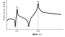
- FIG. 7 is a graph showing the results obtained by the measurement of FIG.
- the horizontal axis is the frequency (Hz), and the vertical axis is the magnitude of acceleration (m / s 2 / N).
- reference numeral P1 is a primary peak.
- the frequency at this primary peak P1 is the out-of-plane primary natural frequency ⁇ o1.
- reference numeral P2 is a secondary peak.
- the frequency at this secondary peak P2 is the out-of-plane secondary natural frequency ⁇ o2.
- FIG. 8A is a plan view showing a method of measuring the cantilever rigidity EI1 in the out-of-plane direction of the racket 2 of FIG. 1, and FIG. 8B is a front view thereof.
- the left-right direction in FIGS. 8A and 8B is the horizontal direction.
- the vertical direction in FIG. 8B is a vertical direction.
- the racket 2 to which the string 12 is not stretched is used for the measurement of the cantilever rigidity EI1.
- the grip is sandwiched between the first block 42 and the second block 44.
- the shape of the first block 42 is a rectangular parallelepiped.
- the shape of the second block 44 is the same as the shape of the first block 42.
- Each of the first block 42 and the second block 44 is arranged so that its front end coincides with the boundary line between the cap 9 and the grip 10.
- FIG. 8 shows the indenter 46.
- the indenter 46 extends in the X direction.
- the indenter 46 is located between the frame 6 and the cap 9 in the Y direction.
- the distance of the indenter 46 from the tip of the cap 9 is 180 mm.
- This indenter 46 is shown in FIG. FIG. 9B shows a cross section of the indenter 46 perpendicular to the length direction.
- the indenter 46 has a contact surface 48.
- the contact surface 48 extends in the length direction of the indenter 46.
- the shape of the contact surface 48 in the cross section of FIG. 9B is an arc.
- the radius R1 of this arc is 5 mm.
- the indenter 46 is located above the shaft 4 and is separated from the shaft 4.
- the indenter 46 gradually moves in the direction indicated by the arrow A. By this movement, the contact surface 48 comes into contact with the shaft 4. After abutting, the indenter 46 continues to move. Due to the movement, a bending load is applied to the shaft 4, and the shaft 4 bends.
- the bending load Fa (N) increases.
- the bending load Fa1 (N) when the moving distance La is 0.5 mm and the bending load Fa2 (N) when the moving distance La is 1.5 mm are measured.
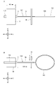
- FIG. 10A is a plan view showing a method of measuring the ball striking rigidity EI2 of the racket 2 of FIG. 1, and FIG. 10B is a front view thereof.
- the left-right direction in FIGS. 10A and 10B is a horizontal direction.
- the vertical direction in FIG. 10B is a vertical direction.
- the racket 2 to which the string 12 is not stretched is used for measuring the ball striking rigidity EI2.
- the frame 6 is supported by the first bar 50 and the second bar 52.
- Each of the first bar 50 and the second bar 52 supports the frame 6 from below.
- the shape of the second bar 52 is the same as the shape of the first bar 50.
- FIG. 11 shows the first bar 50.
- FIG. 11B shows a cross section of the first bar 50 perpendicular to the length direction.
- the first bar 50 has a contact surface 54.
- the contact surface 54 extends in the length direction of the first bar 50.
- the shape of the contact surface 54 in the cross section of FIG. 11B is an arc.
- the radius R2 of this arc is 10 mm.
- the contact surface 54 of the first bar 50 and the second bar 52 is in contact with the frame 6.
- the first bar 50 and the second bar 52 keep the frame 6 horizontal.
- the first bar 50 extends in the X direction.
- the second bar 52 also extends in the X direction.
- the first bar 50 is located behind the top portion 24. The distance from the tip of the top portion 24 to the first bar 50 is 20 mm.
- the second bar 52 is located after the first bar 50. The distance of the second bar 52 from the first bar 50 is 200 mm.
- FIG. 10 shows the indenter 46 described above.
- the indenter 46 extends in the X direction.
- the indenter 46 is located between the first bar 50 and the second bar 52.
- FIG. 10B the indenter 46 is located above the frame 6 and is separated from the frame 6.
- the indenter 46 gradually moves in the direction indicated by the arrow A. By this movement, the contact surface 48 comes into contact with the frame 6. After abutting, the indenter 46 continues to move. Due to the movement, a bending load is applied to the frame 6, and the frame 6 bends. As the moving distance Lb (m) of the indenter 46 after the contact surface 48 comes into contact with the frame 6, the bending load Fb (N) increases.
- the bending load Fb1 (N) when the moving distance Lb is 1.0 mm and the bending load Fb2 (N) when the moving distance Lb is 3.0 mm are measured.
- the value y is calculated by the following mathematical formula (1.3).
- y ( ⁇ o1 * ⁇ o2) 1/2 (1.3)
- ⁇ o1 represents the out-of-plane primary natural frequency (Hz) in the natural vibration of the racket 2
- ⁇ o2 represents the out-of-plane secondary natural frequency (Hz) in the natural vibration of the racket 2.
- the value x is calculated by the following mathematical formula (1.4).
- x EI1 * 7.0 + EI2 * 0.28 + 71.0 (1.4)
- EI1 represents the cantilever rigidity (N / mm) of the racket 2
- EI2 represents the ball striking rigidity (N / mm) of the racket 2.
- FIG. 12 is a graph showing the relationship between the value x and the value y of the badminton racket 2.
- the reference numeral Pr1 represents the point of the racket 2 shown in FIG. 1-5.
- the straight line represented by the reference numeral L1 in FIG. 12 can be represented by the following mathematical formula.
- y x + 5.0
- the racket 2 included in the zone above the straight line L1 has the following mathematical formula (1.1).
- the vibration in the out-of-plane secondary mode is mainly excited.
- the vibration in the out-of-plane primary mode is mainly excited.
- the vibrations of the out-of-plane primary mode and the out-of-plane secondary mode are mainly excited.
- a typical hit point in a drive is near the center FC. Therefore, in the drive, vibrations in the out-of-plane primary mode and the out-of-plane secondary mode are mainly excited.
- the value x is an index that correlates with the hardness of the racket 2.
- the value y is an index that correlates with the repulsion performance of the racket 2.
- the values x and y are indexes found by the present inventor after diligent studies. In the racket 2 satisfying the above formula (1.1), the value y is relatively large with respect to the hardness. As described above, the drive excites vibrations in the out-of-plane primary mode and the out-of-plane secondary mode. However, even in the drive, the hit points vary. According to the knowledge obtained by the present inventor, in the drive by the racket 2 satisfying the above equation (1.1), the variation in the initial speed of the shuttle is small even if the hitting points vary.
- This racket 2 is suitable for a player who makes heavy use of a drive. This racket 2 is also suitable for players who place importance on driving.
- the typical hitting point in the drive is near the center FC.
- the racket 2 satisfying the above formula (1.1) is also suitable for shots other than driving where the shuttle is hit near the center FC.
- the above formula (1.1) can be achieved by changing the position of the prepreg, the number of prepregs, the width of the prepreg, the length of the prepreg, the angle of the fiber, the amount of the grain of the fiber, the elastic modulus of the fiber, and the like on the shaft 4.
- a concrete means (A) The fiber reinforcing layer having a straight structure is unevenly distributed in the chip portion 18. (B) The number of fiber reinforced layers of the chip portion 18 is set large. (C) The fiber reinforced layer having a large basis weight is unevenly distributed in the chip portion 18. (D) A fiber reinforcing layer having fibers having a large elastic modulus is unevenly distributed in the chip portion 18. (E) The number of fiber reinforcing layers of the bad portion 14 is set small.
- the above equation (1.1) may be achieved depending on the specifications of the members other than the shaft 4.
- the frame 6 can be mentioned.
- the above formula (1.1) can be achieved by changing the position of the prepreg, the number of prepregs, the width of the prepreg, the length of the prepreg, the angle of the fiber, the amount of the grain of the fiber, the elastic modulus of the fiber, and the like in the frame 6.
- A Fiber reinforced layers having a straight structure are unevenly distributed in the vicinity of the top 24 of the frame 6.
- B The number of fiber reinforced layers in the vicinity of the top 24 of the frame 6 is set large.
- Fiber reinforced layers having a large basis weight are unevenly distributed in the vicinity of the top 24 of the frame 6.
- the straight line represented by the reference numeral L2 in FIG. 12 can be represented by the following mathematical formula.
- y x --5.0
- the racket 2 included in the zone below the straight line L2 has the following mathematical formula (1.2).
- the value y is relatively small with respect to the hardness.
- the drive excites vibrations in the out-of-plane primary mode and the out-of-plane secondary mode.
- the hit points vary.
- the variation in the initial speed of the shuttle is small even if the hitting points vary. The reason is that the difference between the repulsion of the racket 2 when the shuttle is hit by the center FC and the repulsion of the racket 2 when the shuttle is hit at a position away from the center FC is small. Since the variation in the initial velocity of the shuttle is small, the variation in the trajectory of the shuttle is also small.
- This racket 2 is suitable for a player who makes heavy use of a drive.
- This racket 2 is also suitable for players who place importance on driving.
- the typical hitting point in the drive is near the center FC.
- the racket 2 satisfying the above formula (1.2) is also suitable for shots other than the drive where the shuttle is hit near the center FC.
- the above formula (1.2) can be achieved by changing the position of the prepreg, the number of prepregs, the width of the prepreg, the length of the prepreg, the angle of the fiber, the amount of the grain of the fiber, the elastic modulus of the fiber, and the like on the shaft 4.
- a concrete means (A) The fiber reinforcing layer having a straight structure is unevenly distributed in the bad portion 14. (B) The number of fiber reinforced layers of the bad portion 14 is set large. (C) The fiber reinforced layer having a large basis weight is unevenly distributed in the bad portion 14. (D) A fiber reinforcing layer having fibers having a large elastic modulus is unevenly distributed in the bad portion 14. (E) The number of fiber reinforced layers of the chip portion 18 is set small. (F) The fiber reinforced layer having a small basis weight is unevenly distributed in the chip portion 18. (G) A fiber reinforcing layer having fibers having a small elastic modulus is unevenly distributed in the chip portion 18. Etc. are exemplified.
- the above equation (1.2) may be achieved depending on the specifications of the members other than the shaft 4.
- the frame 6 can be mentioned.
- the above formula (1.2) can be achieved by changing the position of the prepreg, the number of prepregs, the width of the prepreg, the length of the prepreg, the angle of the fiber, the amount of the grain of the fiber, the elastic modulus of the fiber, and the like in the frame 6.
- A Fiber reinforced layers having a straight structure are unevenly distributed in the vicinity of the top 24 and the vicinity of the bottom 26 of the frame 6.
- the number of fiber reinforcing layers in the vicinity of the top 24 and the vicinity of the bottom 26 of the frame 6 is set large.
- Fiber reinforced layers having a large basis weight are unevenly distributed in the vicinity of the top 24 and the vicinity of the bottom 26 of the frame 6.
- (D) Fiber reinforced layers having fibers having a high elastic modulus are unevenly distributed in the vicinity of the top 24 and the vicinity of the bottom 26 of the frame 6. Etc. are exemplified.
- the trajectory stability in the drive can be obtained. From the viewpoint that the shuttle flies at high speed in the drive, the racket 2 satisfying the above equation (1.1) is preferable.
- the straight line represented by the reference numeral L5 in FIG. 12 can be represented by the following mathematical formula.
- y x + 11.0
- the racket 2 included in the zone above the straight line L5 has the following mathematical formula (1.5).
- y ⁇ x + 11.0 (1.5) According to the knowledge obtained by the present inventor, the racket 2 satisfying this equation (1.5) is suitable for driving. A player who drives using this racket 2 can easily obtain the trajectory intended by the shuttle. In this racket 2, the variation in the trajectory of the shuttle in the drive is small. The shuttle hit by this racket 2 flies at high speed.
- the straight line represented by the reference numeral L6 in FIG. 12 can be represented by the following mathematical formula.
- y x --10.5
- the racket 2 included in the zone below the straight line L6 has the following mathematical formula (1.6).
- y ⁇ x --10.5 (1.6) According to the knowledge obtained by the present inventor, the racket 2 satisfying this equation (1.6) is suitable for driving. A player who drives using this racket 2 can easily obtain the trajectory intended by the shuttle. In this racket 2, the variation in the trajectory of the shuttle in the drive is small.
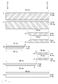
- FIG. 13 is a development view showing a prepreg configuration for a racket shaft according to another embodiment.
- This prepreg configuration has 11 prepregs (ie, sheets). Specifically, this prepreg configuration includes a first sheet S1, a second sheet S2, a third sheet S3, a fourth sheet S4, a fifth sheet S5, a sixth sheet S6, a seventh sheet S7, and an eighth sheet S8. It has a ninth sheet S9, a tenth sheet S10, and an eleventh sheet S11. From these prepregs, a plurality of fiber reinforcing layers are formed by the method described later.
- the first fiber reinforcing layer is formed from the first sheet S1
- the second fiber reinforcing layer is formed from the second sheet S2
- the third fiber reinforcing layer is formed from the third sheet S3, and the fourth sheet.
- the fourth fiber reinforcing layer is formed from S4
- the fifth fiber reinforcing layer is formed from the fifth sheet S5
- the sixth fiber reinforcing layer is formed from the sixth sheet S6,
- the seventh fiber reinforcing layer is formed from the seventh sheet S7.
- the eighth sheet S8 forms the eighth fiber reinforcing layer
- the ninth sheet S9 forms the ninth fiber reinforcing layer
- the tenth sheet S10 forms the tenth fiber reinforcing layer
- the eleventh sheet S11 forms.
- the eleventh fiber reinforcing layer is formed from.
- the left-right direction in FIG. 13 is the axial direction of the shaft.
- the positions of the bad end 20 and the chip end 22 are indicated by arrows.
- the scale in FIG. 13 is not accurate.
- the first sheet S1 exists over the entire shaft.
- the shape of the first sheet S1 is generally rectangular.
- the first sheet S1 contains a plurality of carbon fibers arranged in parallel.
- the extending direction of each carbon fiber is inclined with respect to the axial direction.
- the angle of the extending direction of the carbon fiber with respect to the axial direction is 30 ° or more and 60 ° or less. In this embodiment, this angle is 45 °.
- the first sheet S1 has a width of 60 mm and a length of 340 mm.
- the second seat S2 exists over the entire shaft.
- the shape of the second sheet S2 is substantially rectangular.
- the second sheet S2 contains a plurality of carbon fibers arranged in parallel.
- the extending direction of each carbon fiber is inclined with respect to the axial direction.
- the angle of the extending direction of the carbon fiber with respect to the axial direction is ⁇ 60 ° or more and ⁇ 30 ° or less. In this embodiment, this angle is ⁇ 45 °.
- the second sheet S2 has a width of 60 mm and a length of 340 mm.
- the inclination direction of the carbon fibers in the second sheet S2 is opposite to the inclination direction of the carbon fibers in the first sheet S1. Therefore, the inclination direction of the carbon fibers in the second fiber reinforcing layer is opposite to the inclination direction of the carbon fibers in the first fiber reinforcing layer.
- a bias structure is achieved by a first fiber reinforced layer and a second fiber reinforced layer.
- the first fiber reinforcing layer and the second fiber reinforcing layer contribute to the bending rigidity and the torsional rigidity of the shaft.
- the first fiber reinforcing layer and the second fiber reinforcing layer particularly contribute to the torsional rigidity of the shaft.
- the third seat S3 is unevenly present in the middle part of the shaft.
- the shape of the third sheet S3 is approximately a parallelogram.
- the third sheet S3 contains a plurality of carbon fibers arranged in parallel.
- the extending direction of each carbon fiber is inclined with respect to the axial direction.
- the angle of the extending direction of the carbon fiber with respect to the axial direction is 30 ° or more and 60 ° or less. In this embodiment, this angle is 45 °.
- the third sheet S3 has a width of 19 mm and a length of 70 mm.
- the fourth seat S4 is unevenly present in the middle part of the shaft. In the axial direction, the position of the fourth sheet S4 coincides with the position of the third sheet S3.
- the shape of the fourth sheet S4 is generally a parallelogram.
- the fourth sheet S4 contains a plurality of carbon fibers arranged in parallel. The extending direction of each carbon fiber is inclined with respect to the axial direction. The angle of the extending direction of the carbon fiber with respect to the axial direction is ⁇ 60 ° or more and ⁇ 30 ° or less. In this embodiment, this angle is ⁇ 45 °.
- the fourth sheet S4 has a width of 19 mm and a length of 70 mm.
- the inclination direction of the carbon fibers in the fourth sheet S4 is opposite to the inclination direction of the carbon fibers in the third sheet S3. Therefore, the inclination direction of the carbon fibers in the fourth fiber reinforcing layer is opposite to the inclination direction of the carbon fibers in the third fiber reinforcing layer.
- a bias structure is achieved by a third fiber reinforced layer and a fourth fiber reinforced layer.
- the third fiber reinforcing layer and the fourth fiber reinforcing layer contribute to the flexural rigidity and the torsional rigidity of the middle portion.
- the third fiber reinforcing layer and the fourth fiber reinforcing layer particularly contribute to the torsional rigidity of the middle portion.
- the fifth sheet S5 is biased toward the tip end 22 side of the shaft.
- the shape of the fifth sheet S5 is generally trapezoidal.
- the fifth sheet S5 contains a plurality of carbon fibers arranged in parallel. The extending direction of each carbon fiber coincides with the axial direction. In other words, the angle of the extending direction of the carbon fiber with respect to the axial direction is substantially 0 °.
- the width is 37 mm
- the length of the upper base is 105 mm
- the length of the lower base is 115 mm.
- the carbon fibers contained in the fifth sheet S5 are substantially oriented in the axial direction. Therefore, even in the fifth fiber reinforcing layer, the carbon fibers are substantially axially oriented.
- a structure in which the carbon fibers are substantially axially oriented is referred to as a "straight structure".
- the fifth fiber reinforcing layer has a straight structure. When the shaft bends, a large amount of tension is applied to these carbon fibers. This tension suppresses further deflection of the shaft. In other words, these carbon fibers contribute to the flexural rigidity of the shaft.
- the fifth fiber reinforcing layer particularly contributes to the bending rigidity of the tip portion.
- the sixth seat S6 is biased toward the bad end 20 side of the shaft.
- the shape of the sixth sheet S6 is generally trapezoidal.
- the sixth sheet S6 contains a plurality of carbon fibers arranged in parallel. The extending direction of each carbon fiber coincides with the axial direction. In other words, the angle of the extending direction of the carbon fiber with respect to the axial direction is substantially 0 °.
- the width is 37 mm
- the length of the upper base is 155 mm
- the length of the lower base is 165 mm.
- the carbon fibers contained in the sixth sheet S6 are substantially oriented in the axial direction. Therefore, even in the sixth fiber reinforcing layer, the carbon fibers are substantially axially oriented.
- the sixth fiber reinforcing layer has a straight structure. When the shaft bends, a large amount of tension is applied to these carbon fibers. This tension suppresses further deflection of the shaft. In other words, these carbon fibers contribute to the flexural rigidity of the shaft.
- the sixth fiber reinforcing layer particularly contributes to the bending rigidity of the bad portion.
- the 7th seat S7 is biased toward the bad end 20 side of the shaft.
- the shape of the seventh sheet S7 is generally trapezoidal.
- the seventh sheet S7 contains a plurality of carbon fibers arranged in parallel.
- the extending direction of each carbon fiber is inclined with respect to the axial direction.
- the angle of the extending direction of the carbon fiber with respect to the axial direction is 30 ° or more and 60 ° or less. In this embodiment, this angle is 45 °.
- the width is 46 mm
- the length of the upper base is 235 mm
- the length of the lower base is 245 mm.
- the eighth sheet S8 is biased toward the bad end 20 side of the shaft. In the axial direction, the position of the eighth sheet S8 coincides with the position of the seventh sheet S7.
- the shape of the eighth sheet S8 is generally trapezoidal.
- the eighth sheet S8 contains a plurality of carbon fibers arranged in parallel. The extending direction of each carbon fiber is inclined with respect to the axial direction. The angle of the extending direction of the carbon fiber with respect to the axial direction is ⁇ 60 ° or more and ⁇ 30 ° or less. In this embodiment, this angle is ⁇ 45 °.
- the width is 46 mm
- the length of the upper base is 235 mm
- the length of the lower base is 245 mm.
- the inclination direction of the carbon fibers in the eighth sheet S8 is opposite to the inclination direction of the carbon fibers in the seventh sheet S7. Therefore, the inclination direction of the carbon fibers in the eighth fiber reinforcing layer is opposite to the inclination direction of the carbon fibers in the seventh fiber reinforcing layer.
- the bias structure is achieved by the seventh fiber reinforcing layer and the eighth fiber reinforcing layer.
- the seventh fiber reinforcing layer and the eighth fiber reinforcing layer contribute to the flexural rigidity and the torsional rigidity of the bad portion.
- the seventh fiber reinforcing layer and the eighth fiber reinforcing layer particularly contribute to the torsional rigidity of the bad portion and the middle portion.
- the ninth sheet S9 is biased toward the tip end 22 side of the shaft.
- the shape of the ninth sheet S9 is generally trapezoidal.
- the ninth sheet S9 contains a plurality of carbon fibers arranged in parallel. The extending direction of each carbon fiber coincides with the axial direction. In other words, the angle of the extending direction of the carbon fiber with respect to the axial direction is substantially 0 °.
- the width is 92 mm
- the length of the upper base is 95 mm
- the length of the lower base is 105 mm.
- the carbon fibers contained in the ninth sheet S9 are substantially oriented in the axial direction. Therefore, even in the ninth fiber reinforcing layer, the carbon fibers are substantially axially oriented.
- the ninth fiber reinforcing layer has a straight structure. When the shaft bends, a large amount of tension is applied to these carbon fibers. This tension suppresses further deflection of the shaft. In other words, these carbon fibers contribute to the flexural rigidity of the shaft.
- the ninth fiber reinforcing layer particularly contributes to the bending rigidity of the tip portion.
- the tenth sheet S10 is biased toward the bad end 20 side of the shaft.
- the shape of the tenth sheet S10 is generally trapezoidal.
- the tenth sheet S10 contains a plurality of carbon fibers arranged in parallel.
- the extending direction of each carbon fiber coincides with the axial direction. In other words, the angle of the extending direction of the carbon fiber with respect to the axial direction is substantially 0 °.
- the width is 71 mm
- the length of the upper base is 235 mm
- the length of the lower base is 245 mm.
- the carbon fibers contained in the tenth sheet S10 are substantially oriented in the axial direction. Therefore, even in the tenth fiber reinforcing layer, the carbon fibers are substantially axially oriented.
- the tenth fiber reinforcing layer has a straight structure. When the shaft bends, a large amount of tension is applied to these carbon fibers. This tension suppresses further deflection of the shaft. In other words, these carbon fibers contribute to the flexural rigidity of the shaft.
- the tenth fiber reinforcing layer particularly contributes to the bending rigidity of the bad portion and the middle portion.
- the eleventh sheet S11 is biased toward the tip end 22 side of the shaft.
- the shape of the eleventh sheet S11 is generally trapezoidal.
- the eleventh sheet S11 contains a plurality of carbon fibers arranged in parallel.
- the extending direction of each carbon fiber coincides with the axial direction. In other words, the angle of the extending direction of the carbon fiber with respect to the axial direction is substantially 0 °.
- the width is 71 mm
- the length of the upper base is 95 mm
- the length of the lower base is 105 mm.
- the carbon fibers contained in the eleventh sheet S11 are substantially oriented in the axial direction. Therefore, even in the eleventh fiber reinforced layer, the carbon fibers are substantially axially oriented.
- the eleventh fiber reinforced layer has a straight structure. When the shaft bends, a large amount of tension is applied to these carbon fibers. This tension suppresses further deflection of the shaft. In other words, these carbon fibers contribute to the flexural rigidity of the shaft.
- the eleventh fiber reinforced layer particularly contributes to the bending rigidity of the tip portion.
- the first fiber reinforcing layer and the second fiber reinforcing layer exist from the bad end 20 to the tip end 22. These fiber reinforced layers can contribute to the durability of the shaft.
- the sheets shown in FIG. 13 are sequentially wound around the mandrel.
- the first sheet S1 and the second sheet S2 may be overlapped and wound around a mandrel.
- the third sheet S3 and the fourth sheet S4 may be overlapped and wound around a mandrel.
- the sixth sheet S6 and the seventh sheet S7 may be overlapped and wound around a mandrel.
- other sheets may be wrapped around the mandrel. Examples of other sheets include those containing glass fiber.
- Wrapping tape is further wrapped around these sheets.
- These mandrels, prepregs (sheets S1-S9) and wrapping tapes are heated in an oven or the like. The heating causes the matrix resin to flow. Further heating causes the resin to undergo a curing reaction, and a molded product is obtained. The end face is processed, polished, painted, and the like to complete the shaft.
- the material of this shaft is fiber reinforced plastic.
- the material of the shaft may be a resin composition containing no fibers.
- the material of the shaft may be metal, wood, or the like.
- FIG. 14 is an explanatory diagram showing a method of measuring the frequency of in-plane natural vibration of a racket 102 having a shaft 104 obtained from the prepreg of FIG.
- the racket 102 is suspended by the string 36.
- This racket 102 does not have the string 12.
- the racket 102 without the string 12 is provided for measuring the frequency of the natural vibration.
- the axial direction (Y direction) of the shaft 104 coincides with the vertical direction.
- the shaft 104 is located below the frame 6.
- an acceleration pickup 38 is attached to the racket 102.
- the position of the acceleration pickup 38 is the tip of the grip 110.
- the direction of the acceleration pickup 38 is the X direction.
- the acceleration pickup 38 has a mass of 3.5 g.
- the point Ph of the grip 110 facing the acceleration pickup 38 is vibrated by an impact hammer (not shown).
- the input vibration measured by the force pickup of the impact hammer and the response vibration measured by the acceleration pickup 38 are sent to the frequency analyzer (“Dynamic Signal Analyzer” of Hewlett-Packard Co., Ltd.) via the amplifier. Based on the transfer function obtained by this device, the frequency of the natural vibration in the plane is calculated.
- the direction of the natural vibration in the plane is mainly the X direction. In this method, the natural frequency is measured without being firmly fixed to any part of the racket 102. In other words, the natural frequency is measured under free constraints.
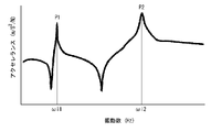
- FIG. 15 is a graph showing the results obtained by the measurements of FIG.
- the horizontal axis is the frequency (Hz), and the vertical axis is the magnitude of acceleration (m / s 2 / N).
- reference numeral P1 is a primary peak.
- the frequency at this primary peak P1 is the in-plane primary natural frequency ⁇ i1.
- reference numeral P2 is a secondary peak.
- the frequency at this secondary peak P2 is the in-plane secondary natural frequency ⁇ i2.
- FIG. 16A is a plan view showing a method of measuring the cantilever rigidity EI1 in the in-plane direction of the racket 102 of FIG. 14, and FIG. 16B is a front view thereof.
- the left-right direction in FIGS. 16A and 16B is a horizontal direction.
- the vertical direction in FIG. 16B is a vertical direction.
- the racket 102 to which the string 12 is not stretched is used for the measurement of the cantilever rigidity EI1.
- the grip is sandwiched between the first block 42 and the second block 44.
- the shape of the first block 42 is a rectangular parallelepiped.
- the shape of the second block 44 is the same as the shape of the first block 42.
- Each of the first block 42 and the second block 44 is arranged so that its front end coincides with the boundary line between the cap 9 and the grip 110.
- Indenter 46 is shown in FIGS. 16A and 16B.
- the indenter 46 extends in the X direction.
- the indenter 46 is located between the frame 6 and the cap 9 in the Y direction.
- the distance of the indenter 46 from the tip of the cap 9 is 180 mm.
- the indenter 46 has the shape shown in FIG.
- the indenter 46 is located above the shaft 104 and is separated from the shaft 104.
- the indenter 46 gradually moves in the direction indicated by the arrow A. By this movement, the contact surface 48 comes into contact with the shaft 104. After abutting, the indenter 46 continues to move. Due to the movement, a bending load is applied to the shaft 104, and the shaft 104 bends.
- the bending load Fa (N) increases as the moving distance La (m) of the indenter 46 after the contact surface 48 abuts on the shaft 104 increases.
- the bending load Fa1 (N) when the moving distance La is 0.5 mm and the bending load Fa2 (N) when the moving distance La is 1.5 mm are measured.
- FIG. 17A is a plan view showing a method of measuring the lateral pressure rigidity EI3 of the racket 102 of FIG. 14, and FIG. 17B is a front view thereof.
- the left-right direction in FIGS. 17A and 17B is a horizontal direction.
- the vertical direction in FIG. 17B is a vertical direction.
- the racket 102 to which the string 12 is not stretched is used for measuring the lateral pressure rigidity EI3.
- the frame 6 is placed on the table 50.
- the axial direction (Y direction) coincides with the horizontal direction
- the width direction (X direction) coincides with the vertical direction.
- a columnar indenter 47 is shown in FIGS. 17A and 17B.
- the indenter 47 is located directly above the maximum width point Pmax. This maximum width point Pmax is a point where the width of the frame 6 is the maximum.
- the indenter 47 is located above the frame 6 and is separated from the frame 6.
- the indenter 47 gradually moves in the direction indicated by the arrow A. By this movement, the contact surface 48 comes into contact with the frame 6. After abutting, the indenter 47 continues to move.
- the bending load Fc (N) increases as the moving distance Lc (m) of the indenter 47 after the contact surface 48 comes into contact with the frame 6 increases.
- the bending load Fc1 (N) when the moving distance Lc is 0.5 mm and the bending load Fc2 (N) when the moving distance Lc is 2.5 mm are measured.
- the value y is calculated by the following mathematical formula (2.3).
- y ( ⁇ i1 * ⁇ i2) 1/2 (2.3)
- ⁇ i1 represents the in-plane primary natural frequency (Hz) in the natural vibration of the racket 102
- ⁇ i2 represents the in-plane secondary natural frequency (Hz) in the natural vibration of the racket 102.
- the value x is calculated by the following mathematical formula (2.4).
- x EI1 * 8.0 + EI3 * 0.46 + 78.0 (2.4)
- EI1 represents the cantilever rigidity (N / mm) of the racket 102
- EI3 represents the lateral pressure rigidity (N / mm) of the racket 102.
- FIG. 18 is a graph showing the relationship between the value x and the value y of the badminton racket 102.
- the reference numeral Pr represents the point of the racket 102 shown in FIG.
- the straight line represented by the reference numeral L1 in FIG. 18 can be represented by the following mathematical formula.
- y x + 5.0
- the racket 102 included in the zone above the straight line L1 includes the following mathematical formula (2.1). y ⁇ x + 5.0 (2.1)
- the vibration in the in-plane secondary mode is mainly excited.
- the vibration in the in-plane primary mode is mainly excited.
- the vibrations of the in-plane primary mode and the in-plane secondary mode are mainly excited.
- a typical RBI in driven clear is near the center FC. Therefore, in the driven clear, the vibrations of the in-plane primary mode and the in-plane secondary mode are mainly excited.
- the value x is an index that correlates with the hardness of the racket 102.
- the value y is an index that correlates with the repulsion performance of the racket 102.
- the values x and y are indexes found by the present inventor after diligent studies. In the racket 102 satisfying the above formula (2.1), the value y is relatively large with respect to the hardness. As described above, in the driven clear, the vibrations of the in-plane primary mode and the in-plane secondary mode are excited. However, even in driven clear, the RBIs vary. According to the findings obtained by the present inventor, in the driven clear by the racket 102 satisfying the above equation (2.1), the variation in the initial speed of the shuttle is small even if the hitting points vary.
- the reason is that the repulsion of the racket 102 is not extremely small even if the shuttle is hit at a position deviated from the intended position. Since the variation in the initial velocity of the shuttle is small, the variation in the trajectory of the shuttle is also small.
- This racket 102 is suitable for a player who makes heavy use of driven clear. This racket 102 is also suitable for players who place importance on driven clearing.
- the typical RBI in driven clear is near the center FC.
- the racket 102 that satisfies the above formula (2.1) is also suitable for shots other than driven clear where the shuttle is hit near the center FC.
- the above equation (2.1) can be achieved by changing the position of the prepreg, the number of prepregs, the width of the prepreg, the length of the prepreg, the angle of the fiber, the amount of the grain of the fiber, the elastic modulus of the fiber, and the like on the shaft 104.
- A The fiber reinforced layer having a straight structure is unevenly distributed in the chip portion.
- B The number of fiber reinforced layers in the chip portion is set large.
- the fiber reinforced layer having a large basis weight is unevenly distributed in the chip portion.
- D) A fiber reinforcing layer having fibers having a large elastic modulus is unevenly distributed in the chip portion.
- Set the number of fiber reinforced layers in the bad portion to be small.
- the above equation (2.1) may be achieved depending on the specifications of the members other than the shaft 104.
- the frame 6 can be mentioned.
- the above formula (2.1) can be achieved by changing the position of the prepreg, the number of prepregs, the width of the prepreg, the length of the prepreg, the angle of the fiber, the amount of the grain of the fiber, the elastic modulus of the fiber, and the like in the frame 6.
- A Fiber reinforced layers having a straight structure are unevenly distributed in the vicinity of the top 24 of the frame 6.
- B The number of fiber reinforced layers in the vicinity of the top 24 of the frame 6 is set large.
- Fiber reinforced layers having a large basis weight are unevenly distributed in the vicinity of the top 24 of the frame 6.
- D Fiber reinforced layers having fibers having a high elastic modulus are unevenly distributed in the vicinity of the top 24 of the frame 6.
- the number of fiber reinforced layers in the vicinity of the bottom 26 of the frame 6 is set small.
- F Fiber reinforced layers having a small basis weight are unevenly distributed in the vicinity of the bottom 26 of the frame 6.
- G Fiber reinforced layers having fibers having a small elastic modulus are unevenly distributed in the vicinity of the bottom 26 of the frame 6. Etc. are exemplified.
- the straight line represented by the reference numeral L2 in FIG. 18 can be represented by the following mathematical formula.
- y x --6.0
- the racket 102 included in the zone below the straight line L2 includes the following mathematical formula (2.2).
- the value y is relatively small with respect to the hardness.
- the vibrations of the in-plane primary mode and the in-plane secondary mode are excited.
- the RBIs vary.
- the variation in the initial speed of the shuttle is small even if the hitting points vary. The reason is that the difference between the repulsion of the racket 102 when the shuttle is hit by the center FC and the repulsion of the racket 102 when the shuttle is hit at a position away from the center FC is small. Since the variation in the initial velocity of the shuttle is small, the variation in the trajectory of the shuttle is also small.
- This racket 102 is suitable for a player who makes heavy use of driven clear.
- This racket 102 is also suitable for players who place importance on driven clearing.
- the typical RBI in driven clear is near the center FC.
- the racket 102 that satisfies the above formula (2.2) is also suitable for shots other than driven clear, in which the shuttle is hit near the center FC and accompanied by a cut.
- the above equation (2.2) can be achieved by changing the position of the prepreg, the number of prepregs, the width of the prepreg, the length of the prepreg, the angle of the fiber, the amount of the grain of the fiber, the elastic modulus of the fiber, and the like on the shaft 104.
- a concrete means (A) The fiber reinforced layer having a straight structure is unevenly distributed in the bad portion. (B) The number of fiber reinforced layers in the bad portion is set large. (C) The fiber reinforced layer having a large basis weight is unevenly distributed in the bad portion. (D) A fiber reinforcing layer having fibers having a large elastic modulus is unevenly distributed in the bad portion. (E) The number of fiber reinforced layers in the chip portion is set small. (F) Fiber reinforced layers having a small basis weight are unevenly distributed in the chip portion. (G) A fiber reinforcing layer having fibers having a small elastic modulus is unevenly distributed in the chip portion. Etc. are exemplified.
- the above equation (2.2) may be achieved depending on the specifications of members other than the shaft 104.
- the frame 6 can be mentioned.
- the above formula (2.2) can be achieved by changing the position of the prepreg, the number of prepregs, the width of the prepreg, the length of the prepreg, the angle of the fiber, the amount of the grain of the fiber, the elastic modulus of the fiber, and the like in the frame 6.
- A Fiber reinforced layers having a straight structure are unevenly distributed in the vicinity of the top 24 and the vicinity of the bottom 26 of the frame 6.
- the number of fiber reinforcing layers in the vicinity of the top 24 and the vicinity of the bottom 26 of the frame 6 is set large.
- Fiber reinforced layers having a large basis weight are unevenly distributed in the vicinity of the top 24 and the vicinity of the bottom 26 of the frame 6.
- (D) Fiber reinforced layers having fibers having a high elastic modulus are unevenly distributed in the vicinity of the top 24 and the vicinity of the bottom 26 of the frame 6. Etc. are exemplified.
- the straight line represented by the reference numeral L5 in FIG. 18 can be represented by the following mathematical formula.
- y x + 14.0
- the racket 102 included in the zone above the straight line L5 includes the following mathematical formula (2.5).
- y ⁇ x + 14.0 (2.5) According to the knowledge obtained by the present inventor, the racket 102 satisfying this equation (2.5) is suitable for driven clearing. A player who performs a driven clear using this racket 102 can easily obtain the trajectory intended by the shuttle. In this racket 102, the variation in the trajectory of the shuttle in the driven clear is small. The shuttle hit by this racket 102 flies at high speed.
- the straight line represented by the reference numeral L6 in FIG. 18 can be represented by the following mathematical formula.
- y x --14.0
- the racket 102 included in the zone below the straight line L6 includes the following mathematical formula (2.6).
- y ⁇ x --14.0 (2.6) According to the knowledge obtained by the present inventor, the racket 102 satisfying this equation (2.6) is suitable for driven clearing. A player who performs a driven clear using this racket 102 can easily obtain the trajectory intended by the shuttle. In this racket 102, the variation in the trajectory of the shuttle in the driven clear is small.
- Example 1-1 A shaft having the prepreg configuration shown in FIG. 5 was manufactured. However, the first sheet S1 and the second sheet S2 were not used in this shaft. Each prepreg contained carbon fiber. The tensile elastic modulus of the carbon fibers in the fifth sheet S5, the ninth sheet S9 and the eleventh sheet S11 was 55 tf / mm 2 . The tensile elastic modulus of the carbon fibers in the residual sheet was 16 tf / mm 2 .
- a badminton racket was manufactured by attaching a frame, neck, cap and grip used in a commercially available badminton racket having standard hardness and mass to this shaft.
- the out-of-plane primary natural frequency ⁇ o1 of this racket is 70 Hz
- the out-of-plane secondary natural frequency ⁇ o2 is 200 Hz
- the cantilever rigidity EI1 is 1.4 N / mm
- the ball striking rigidity EI2 is 60.9 N. It was / mm.
- the coordinates of this racket are indicated by the reference numeral Pr2 in FIG.
- Examples 1-2 to 1-19 and Comparative Examples 1-1 to 1-10 The badminton rackets of Examples 1-2 to 1-19 and Comparative Examples 1-1 to 1-10 were obtained in the same manner as in Example 1 except that the prepreg configuration was as shown in Table 1-6.
- the widths of the prepregs for the shafts of these rackets are shown in Table 1-6 below.
- the out-of-plane primary natural frequency ⁇ o1, the out-of-plane secondary natural frequency ⁇ o2 the cantilever rigidity EI1 and the ball striking rigidity EI2 of these rackets are shown in Table 1-6 below.
- the values x and y of these rackets are shown in FIG.
- Example 2-1 A shaft having the prepreg configuration shown in FIG. 13 was manufactured. Each prepreg contained carbon fiber. The tensile elastic modulus of the carbon fibers in the fifth sheet S5, the ninth sheet S9 and the eleventh sheet S11 was 39 tf / mm 2 . The tensile elastic modulus of the carbon fibers in the residual sheet was 16 tf / mm 2 . A badminton racket was manufactured by attaching a frame, neck, cap and grip used in a commercially available badminton racket having standard hardness and mass to this shaft.
- the in-plane primary natural frequency ⁇ i1 of this racket is 64 Hz
- the in-plane secondary natural frequency ⁇ i2 is 253 Hz
- the cantilever rigidity EI1 is 1.4 N / mm
- the lateral pressure rigidity EI3 is 24.5 N / mm. It was mm.
- the coordinates of this racket are indicated by the reference numeral Pr in FIG.
- Examples 2-2 to 2-21 and Comparative Examples 2-1 to 2-11 The badminton rackets of Examples 2-2 to 2-21 and Comparative Examples 2-1 to 2-11 were obtained in the same manner as in Example 2-1 except that the prepreg configuration was as shown in Table 7-14. .. The width of the prepreg for the shafts of these rackets is shown in Table 7-14 below.
- the in-plane primary natural frequency ⁇ i1, the in-plane secondary natural frequency ⁇ i2, the cantilever stiffness EI1 and the lateral pressure stiffness EI3 of these rackets are shown in Table 7-14 below.
- the values x and y of these rackets are shown in FIG.
- ⁇ o1 represents the out-of-plane primary natural frequency (Hz) in the natural vibration of the badminton racket under the free constraint condition
- ⁇ o2 represents the natural vibration of the badminton racket under the free constraint condition.
- EI1 represents the cantilever rigidity (N / mm) of the badminton racket
- EI2 represents the ball striking rigidity (N / mm) of the badminton racket.
- ⁇ i1 represents the in-plane primary natural frequency (Hz) in the natural vibration of the badminton racket
- ⁇ i2 represents the in-plane secondary natural frequency (Hz) in the natural vibration of the badminton racket.
- EI1 represents the cantilever rigidity (N / mm) of the badminton racket
- EI3 represents the lateral pressure rigidity (N / mm) of the badminton racket.
- the badminton racket described above is suitable for players who make heavy use of drive or driven clear. This racket is also suitable for players who make heavy use of other shots where the RBI is near the center.
- Second bar 54 ... ⁇ Contact surface S1 ⁇ ⁇ ⁇ 1st sheet S2 ⁇ ⁇ ⁇ 2nd sheet S3 ⁇ ⁇ ⁇ 3rd sheet S4 ⁇ ⁇ ⁇ 4th sheet S5 ⁇ ⁇ ⁇ 5th sheet S6 ⁇ ⁇ ⁇ 6th sheet S7 ⁇ ⁇ ⁇ 7th sheet S8 ... 8th sheet S9 ... 9th sheet
Landscapes
- Health & Medical Sciences (AREA)
- General Health & Medical Sciences (AREA)
- Physical Education & Sports Medicine (AREA)
- Golf Clubs (AREA)
- Laminated Bodies (AREA)
Abstract
バドミントンラケット2は、下記数式(1.1)又は(1.2)を満たす。 y ≧x + 5.0 (1.1) y ≦x - 5.0 (1.2) 数式(1.1)及び(1.2)におけるyは、下記数式(1.3)によって算出される。 y = ( ωo1 * ωo2)1/2 (1.3) 数式(1.1)及び(1.2)におけるxは、下記数式(1.4)によって算出される。 x = EI1 * 7.0 + EI2 * 0.28 + 71.0 (1.4) 数式(1.3)において、ωo1はラケット2の自由な拘束条件下での固有振動における面外一次固有振動数(Hz)を表し、ωo2はラケット2のこの固有振動における面外二次固有振動数(Hz)を表す。数式(1.4)において、EI1はラケット2の片持ち剛性(N/mm)を表し、EI2はラケット2の打球面剛性(N/mm)を表す。
Description
本明細書は、バドミントンに使用されるラケットを開示する。
バドミントンのラケットは、フレーム、ストリング及びシャフトを有している。フレームは、トップとボトムとを有している。ストリングは、フェースを形成している。プレーヤーは、ラケットでシャトルをショットする。ショットにより、フェースがシャトルと衝突する。衝突による衝撃は、ストリングからフレームを経てシャフトへと伝わる。ショットにより、フレーム及びシャフトが変形する。衝突時の変形挙動の適正化に関する試みが、特開2001-70481公報に記載されている。
バドミントンのゲームでは、プレーヤーは、様々な種類のショットを行う。スマッシュ、ロビング、ドライブ、ドリブンクリア等のショットを、プレーヤーは行う。統計的手法による調査では、スマッシュにおける典型的な打点はボトム寄りであり、ロビングにおける典型的な打点はトップ寄りである。一方、ドライブにおける典型的な打点は、センター近傍である。
ドライブでは、シャトルが高速でかつほぼ水平に飛行する。ドライブは、相手プレーヤーの体勢を崩す。ゲームの勝利の観点から、ドライブは、重要なショットである。
ドライブでは、ネットを超える高さでシャトルが飛行する必要がある。意図した高さでシャトルを飛行させる技量が、プレーヤーには必要である。ドライブを多用するプレーヤーは、シャトルの弾道の安定を望んでいる。
ドリブンクリアにおける典型的な打点も、センター近傍である。ノーマルなクリアと異なり、ドリブンクリアは、カットの動作を伴う。従ってドリブンクリアでは、シャトルが回転する。この回転により、シャトルは減速する。この減速は、相手プレーヤーの体勢を崩す。ゲームの勝利の観点から、ドリブンクリアは、重要なショットである。
ドリブンクリアでは、ネットを超える高さでシャトルが飛行する必要がある。ドリブンクリアではさらに、シャトルは、相手コートを超えない低さで飛行する必要がある。意図した高さでシャトルを飛行させる技量が、プレーヤーには必要である。ドリブンクリアを多用するプレーヤーは、シャトルの弾道の安定を望んでいる。
本出願人の意図するところは、打点がセンター近傍であるショットにおいて、シャトルの弾道のバラツキが抑制されうる、バドミントンラケットの提供にある。
好ましいバドミントンラケットは、
バッドエンド及びチップエンドを有するシャフト、
上記シャフトの、上記バッドエンドの近傍が挿入されるグリップ、
並びに
上記チップエンドの近傍において上記シャフトに取り付けられたフレーム
を有している。このラケットは、、
下記数式(1.1)又は(1.2)を満たす。
y ≧x + 5.0 (1.1)
y ≦x - 5.0 (1.2)
これらの数式(1.1)及び(1.2)におけるyは、下記数式(1.3)によって算出される。
y = ( ωo1 * ωo2)1/2 (1.3)
これらの数式(1.1)及び(1.2)におけるxは、下記数式(1.4)によって算出される。
x = EI1 * 7.0 + EI2 * 0.28 + 71.0 (1.4)
この数式(1.3)において、ωo1はラケットの自由な拘束条件下での固有振動における面外一次固有振動数(Hz)を表し、ωo2はラケットの自由な拘束条件下での固有振動における面外二次固有振動数(Hz)を表す。この数式(1.4)において、EI1はラケットの片持ち剛性(N/mm)を表し、EI2はラケットの打球面剛性(N/mm)を表す。
バッドエンド及びチップエンドを有するシャフト、
上記シャフトの、上記バッドエンドの近傍が挿入されるグリップ、
並びに
上記チップエンドの近傍において上記シャフトに取り付けられたフレーム
を有している。このラケットは、、
下記数式(1.1)又は(1.2)を満たす。
y ≧x + 5.0 (1.1)
y ≦x - 5.0 (1.2)
これらの数式(1.1)及び(1.2)におけるyは、下記数式(1.3)によって算出される。
y = ( ωo1 * ωo2)1/2 (1.3)
これらの数式(1.1)及び(1.2)におけるxは、下記数式(1.4)によって算出される。
x = EI1 * 7.0 + EI2 * 0.28 + 71.0 (1.4)
この数式(1.3)において、ωo1はラケットの自由な拘束条件下での固有振動における面外一次固有振動数(Hz)を表し、ωo2はラケットの自由な拘束条件下での固有振動における面外二次固有振動数(Hz)を表す。この数式(1.4)において、EI1はラケットの片持ち剛性(N/mm)を表し、EI2はラケットの打球面剛性(N/mm)を表す。
このバドミントンラケットを使用するプレーヤーは、打点がセンター近傍であるショットを行いやすい。このラケットは、ゲームの勝利に寄与しうる。
以下、適宜図面が参照されつつ、好ましい実施形態が詳細に説明される。
図1及び2に、バドミントンラケット2が示されている。このラケット2は、シャフト4、フレーム6、ネック8、キャップ9、グリップ10及びストリング12を有している。図1及び2において、矢印Xは幅方向を表し、矢印Yは軸方向を表し、矢印Zは厚み方向を表す。
シャフト4は、バッド部14、ミドル部16及びチップ部18を有している。シャフト4はさらに、バッドエンド20及びチップエンド22を有している。シャフト4は、中空である。シャフト4は、繊維強化樹脂から形成されている。この繊維強化樹脂は、樹脂マトリックスと、多数の強化繊維とを有している。シャフト4は、複数の繊維強化層(後に詳説)を含んでいる。
シャフト4の基材樹脂として、エポキシ樹脂、ピスマレイミド樹脂、ポリイミド及びフェノール樹脂のような熱硬化性樹脂;並びにポリエーテルエーテルケトン、ポリエーテルサルホン、ポリエーテルイミド、ポリフェニレンサルファイド、ポリアミド及びポリプロピレンのような熱可塑性樹脂が例示される。シャフト4に特に適した樹脂は、エポキシ樹脂である。
シャフト4の強化繊維として、カーボン繊維、金属繊維、ガラス繊維及びアラミド繊維が例示される。シャフト4に特に適した繊維は、カーボン繊維である。複数種の繊維が併用されてもよい。
フレーム6は環状であり、中空である。フレーム6は、繊維強化樹脂から形成されている。この繊維強化樹脂には、シャフト4の基材樹脂と同様の基材樹脂が用いられ得る。この繊維強化樹脂には、シャフト4の強化繊維と同様の強化繊維が用いられ得る。フレーム6は、ネック8を介して、シャフト4のチップエンド22に堅固に結合されている。フレーム6は、トップ24及びボトム26を有している。
グリップ10は、軸方向(Y方向)に延びる穴27を有している。この穴27に、シャフト4のバッドエンド20の近傍が挿入されている。穴27の内周面とシャフト4の外周面とは、接着剤で接合されている。
ストリング12は、フレーム6に張られている。ストリング12は、幅方向X及び軸方向Yに沿って張られる。ストリング12のうち幅方向Xに沿って延在する部分は、横スレッド28と称される。ストリング12のうち軸方向Yに沿って延在する部分は、縦スレッド30と称される。複数の横スレッド28及び複数の縦スレッド30により、フェース32が形成されている。フェース32は、概してX-Y平面に沿っている。図1において矢印Lfは、フェース32の長さを表す。長さLfは、Y方向に沿って測定される。
図1において符号FCは、フェース32のセンターを表す。センターFCは、X方向におけるフェース32の中点であり、Y方向におけるフェース32の中点である。
図1において符号34は、シャフト4の露出部を表す。露出部34は、ネック8から露出しており、かつグリップ10から露出している。図1において符号Lsは、この露出部34の長さである。長さLsは、通常は、150mm以上210mm以下である。
図3は、図1のラケット2のシャフト4の一部が示された拡大断面図である。図4は、図3のIV-IV線に沿った拡大断面図である。前述の通り、このシャフト4は中空である。図4に示されるように、このシャフト4の断面形状は、円である。換言すれば、このシャフト4は、円筒状である。
図3及び4において矢印Diは、シャフト4の内径を表す。典型的な内径Diは、3mm以上10mm以下である。図3及び4において矢印Doは、シャフト4の外径を表す。典型的な外径Doは、5mm以上15mm以下である。
前述の通りシャフト4は、繊維強化樹脂から形成されている。このシャフト4は、シートワインディング法によって製造されうる。このシートワインディング法では、複数のプリプレグが、マンドレルに巻かれる。それぞれのプリプレグは、複数の繊維とマトリックス樹脂とを有する。このマトリックス樹脂は、硬化していない。
図5は、図1のラケット2のシャフト4のためのプリプレグ構成が示された展開図である。このプリプレグ構成は、11のプリプレグ(つまりシート)を有する。具体的には、このプリプレグ構成は、第一シートS1、第二シートS2、第三シートS3、第四シートS4、第五シートS5、第六シートS6、第七シートS7、第八シートS8、第九シートS9、第十シートS10及び第11シートS11を有する。これらのプリプレグから、後述される方法にて、複数の繊維強化層が形成される。具体的には、第一シートS1から第一繊維強化層が形成され、第二シートS2から第二繊維強化層が形成され、第三シートS3から第三繊維強化層が形成され、第四シートS4から第四繊維強化層が形成され、第五シートS5から第五繊維強化層が形成され、第六シートS6から第六繊維強化層が形成され、第七シートS7から第七繊維強化層が形成され、第八シートS8から第八繊維強化層が形成され、第九シートS9から第九繊維強化層が形成され、第十シートS10から第十繊維強化層が形成され、第十一シートS11から第十一繊維強化層が形成される。
図5における左右方向は、シャフト4の軸方向である。図5には、バッドエンド20及びチップエンド22の位置が、矢印で示されている。説明の便宜上、図5において、左右方向(軸方向)の縮尺は、上下方向の縮尺と一致していない。
第一シートS1は、シャフト4の全体に渡って存在している。第一シートS1の形状は、概ね矩形である。この第一シートS1は、並列された複数のカーボン繊維を含んでいる。それぞれのカーボン繊維の延在方向は、軸方向に対して傾いている。このカーボン繊維の延在方向の、軸方向に対する角度は、30°以上60°以下である。本実施形態では、この角度は45°である。この第一シートS1では、幅は70mmであり、長さは340mmである。
第二シートS2は、シャフト4の全体に渡って存在している。第二シートS2の形状は、概ね矩形である。この第二シートS2は、並列された複数のカーボン繊維を含んでいる。それぞれのカーボン繊維の延在方向は、軸方向に対して傾いている。このカーボン繊維の延在方向の、軸方向に対する角度は、-60°以上-30°以下である。本実施形態では、この角度は-45°である。この第二シートS2では、幅は70mmであり、長さは340mmである。
第二シートS2におけるカーボン繊維の傾斜方向は、第一シートS1におけるカーボン繊維の傾斜方向とは逆である。従って、第二繊維強化層におけるカーボン繊維の傾斜方向は、第一繊維強化層におけるカーボン繊維の傾斜方向とは逆である。このシャフト4では第一繊維強化層及び第二繊維強化層により、バイアス構造が達成されている。第一繊維強化層及び第二繊維強化層は、シャフト4の曲げ剛性及びねじり剛性に寄与する。第一繊維強化層及び第二繊維強化層は、特に、シャフト4のねじり剛性に寄与する。
第三シートS3は、シャフト4のミドル部16に偏って存在している。第三シートS3の形状は、概ね平行四辺形である。この第三シートS3は、並列された複数のカーボン繊維を含んでいる。それぞれのカーボン繊維の延在方向は、軸方向に対して傾いている。このカーボン繊維の延在方向の、軸方向に対する角度は、30°以上60°以下である。本実施形態では、この角度は45°である。この第三シートS3では、幅は15.5mmであり、長さは70mmである。
第四シートS4は、シャフト4のミドル部16に偏って存在している。軸方向において、第四シートS4の位置は、第三シートS3の位置と一致している。第四シートS4の形状は、概ね平行四辺形である。この第四シートS4は、並列された複数のカーボン繊維を含んでいる。それぞれのカーボン繊維の延在方向は、軸方向に対して傾いている。このカーボン繊維の延在方向の、軸方向に対する角度は、-60°以上-30°以下である。本実施形態では、この角度は-45°である。この第四シートS4では、幅は15.5mmであり、長さは70mmである。
第四シートS4におけるカーボン繊維の傾斜方向は、第三シートS3におけるカーボン繊維の傾斜方向とは逆である。従って、第四繊維強化層におけるカーボン繊維の傾斜方向は、第三繊維強化層におけるカーボン繊維の傾斜方向とは逆である。このシャフト4では、第三繊維強化層及び第四繊維強化層により、バイアス構造が達成されている。第三繊維強化層及び第四繊維強化層は、ミドル部16の曲げ剛性及びねじり剛性に寄与する。第三繊維強化層及び第四繊維強化層は、特に、ミドル部16のねじり剛性に寄与する。
第五シートS5は、シャフト4のチップエンド22側に偏って存在している。第五シートS5の形状は、概ね台形である。この第五シートS5は、並列された複数のカーボン繊維を含んでいる。それぞれのカーボン繊維の延在方向は、軸方向に一致している。換言すれば、このカーボン繊維の延在方向の、軸方向に対する角度は、実質的に0°である。この第五シートS5では、幅は31mmであり、上底の長さは105mmであり、下底の長さは115mmである。
前述の通り、第五シートS5に含まれるカーボン繊維は、実質的に軸方向に配向している。従って、第五繊維強化層でも、カーボン繊維は実質的に軸方向に配向している。本明細書では、カーボン繊維が実質的に軸方向に配向する構造は、「ストレート構造」と称される。第五繊維強化層は、ストレート構造を有する。シャフト4が撓んだとき、これらのカーボン繊維に大きな張力がかかる。この張力は、シャフト4のさらなる撓みを抑制する。換言すれば、これらのカーボン繊維は、シャフト4の曲げ剛性に寄与する。第五繊維強化層は、特に、チップ部18の曲げ剛性に寄与する。
第六シートS6は、シャフト4のバッドエンド20側に偏って存在している。第六シートS6の形状は、概ね台形である。この第六シートS6は、並列された複数のカーボン繊維を含んでいる。それぞれのカーボン繊維の延在方向は、軸方向に一致している。換言すれば、このカーボン繊維の延在方向の、軸方向に対する角度は、実質的に0°である。この第六シートS6では、幅は31mmであり、上底の長さは155mmであり、下底の長さは165mmである。
前述の通り、第六シートS6に含まれるカーボン繊維は、実質的に軸方向に配向している。従って、第六繊維強化層でも、カーボン繊維は実質的に軸方向に配向している。第六繊維強化層は、ストレート構造を有する。シャフト4が撓んだとき、これらのカーボン繊維に大きな張力がかかる。この張力は、シャフト4のさらなる撓みを抑制する。換言すれば、これらのカーボン繊維は、シャフト4の曲げ剛性に寄与する。第六繊維強化層は、特に、バッド部14の曲げ剛性に寄与する。
第7シートS7は、シャフト4のバッドエンド20側に偏って存在している。第7シートS7の形状は、概ね台形である。この第7シートS7は、並列された複数のカーボン繊維を含んでいる。それぞれのカーボン繊維の延在方向は、軸方向に対して傾いている。このカーボン繊維の延在方向の、軸方向に対する角度は、30°以上60°以下である。本実施形態では、この角度は45°である。この第7シートS7では、幅は38.5mmであり、上底の長さは235mmであり、下底の長さは245mmである。
第八シートS8は、シャフト4のバッドエンド20側に偏って存在している。軸方向において、第八シートS8の位置は、第七シートS7の位置と一致している。第八シートS8の形状は、概ね台形である。この第八シートS8は、並列された複数のカーボン繊維を含んでいる。それぞれのカーボン繊維の延在方向は、軸方向に対して傾いている。このカーボン繊維の延在方向の、軸方向に対する角度は、-60°以上-30°以下である。本実施形態では、この角度は-45°である。この第八シートS8では、幅は38.5mmであり、上底の長さは235mmであり、下底の長さは245mmである。
第八シートS8におけるカーボン繊維の傾斜方向は、第七シートS7におけるカーボン繊維の傾斜方向とは逆である。従って、第八繊維強化層におけるカーボン繊維の傾斜方向は、第七繊維強化層におけるカーボン繊維の傾斜方向とは逆である。このシャフト4では、第七繊維強化層及び第八繊維強化層により、バイアス構造が達成されている。第七繊維強化層及び第八繊維強化層は、バッド部14の曲げ剛性及びねじり剛性に寄与する。第七繊維強化層及び第八繊維強化層は、特に、バッド部14及びミドル部16のねじり剛性に寄与する。
第九シートS9は、シャフト4のチップエンド22側に偏って存在している。第九シートS9の形状は、概ね台形である。この第九シートS9は、並列された複数のカーボン繊維を含んでいる。それぞれのカーボン繊維の延在方向は、軸方向に一致している。換言すれば、このカーボン繊維の延在方向の、軸方向に対する角度は、実質的に0°である。この第九シートS9では、幅は77mmであり、上底の長さは95mmであり、下底の長さは105mmである。
前述の通り、第九シートS9に含まれるカーボン繊維は、実質的に軸方向に配向している。従って、第九繊維強化層でも、カーボン繊維は実質的に軸方向に配向している。第九繊維強化層は、ストレート構造を有する。シャフト4が撓んだとき、これらのカーボン繊維に大きな張力がかかる。この張力は、シャフト4のさらなる撓みを抑制する。換言すれば、これらのカーボン繊維は、シャフト4の曲げ剛性に寄与する。第九繊維強化層は、特に、チップ部18の曲げ剛性に寄与する。
第十シートS10は、シャフト4のバッドエンド20側に偏って存在している。第十シートS10の形状は、概ね台形である。この第十シートS10は、並列された複数のカーボン繊維を含んでいる。それぞれのカーボン繊維の延在方向は、軸方向に一致している。換言すれば、このカーボン繊維の延在方向の、軸方向に対する角度は、実質的に0°である。この第十シートS10では、幅は72mmであり、上底の長さは235mmであり、下底の長さは245mmである。
前述の通り、第十シートS10に含まれるカーボン繊維は、実質的に軸方向に配向している。従って、第10繊維強化層でも、カーボン繊維は実質的に軸方向に配向している。第10繊維強化層は、ストレート構造を有する。シャフト4が撓んだとき、これらのカーボン繊維に大きな張力がかかる。この張力は、シャフト4のさらなる撓みを抑制する。換言すれば、これらのカーボン繊維は、シャフト4の曲げ剛性に寄与する。第10繊維強化層は、特に、バッド部14及びミドル部16の曲げ剛性に寄与する。
第十一シートS11は、シャフト4のチップエンド22側に偏って存在している。第十一シートS11の形状は、概ね台形である。この第十一シートS11は、並列された複数のカーボン繊維を含んでいる。それぞれのカーボン繊維の延在方向は、軸方向に一致している。換言すれば、このカーボン繊維の延在方向の、軸方向に対する角度は、実質的に0°である。この第十一シートS11では、幅は72mmであり、上底の長さは95mmであり、下底の長さは105mmである。
前述の通り、第十一シートS11に含まれるカーボン繊維は、実質的に軸方向に配向している。従って、第十一繊維強化層でも、カーボン繊維は実質的に軸方向に配向している。第十一繊維強化層は、ストレート構造を有する。シャフト4が撓んだとき、これらのカーボン繊維に大きな張力がかかる。この張力は、シャフト4のさらなる撓みを抑制する。換言すれば、これらのカーボン繊維は、シャフト4の曲げ剛性に寄与する。第十一繊維強化層は、特に、チップ部18の曲げ剛性に寄与する。
このシャフト4では、第一繊維強化層及び第二繊維強化層は、バッドエンド20からチップエンド22に渡って存在している。これらの繊維強化層は、シャフト4の耐久性に寄与しうる。
このシャフト4の製造では、図5に示されたシートが、順次、マンドレルに巻かれる。第一シートS1と第二シートS2とが重ねられて、マンドレルに巻かれてもよい。第三シートS3と第四シートS4とが重ねられて、マンドレルに巻かれてもよい。第六シートS6と第七シートS7とが重ねられて、マンドレルに巻かれてもよい。これらのシートと共に、他のシートがマンドレルに巻かれてもよい。他のシートとして、ガラス繊維を含むものが例示される。
これらのシートに、さらにラッピングテープが巻かれる。これらのマンドレル、プリプレグ(シートS1-S9)及びラッピングテープは、オーブン等で加熱される。加熱により、マトリックスの樹脂が流動する。さらなる加熱によりこの樹脂が硬化反応を起こし、成形体が得られる。この成形体に、端面の加工、研磨、塗装等の処理が施され、シャフト4が完成する。
このシャフト4の材質は、繊維強化樹脂である。シャフト4の材質が、繊維を含まない樹脂組成物であってもよい。シャフト4の材質が、金属、木材等であってもよい。
図6は、図1のラケット2の面外固有振動の振動数の測定方法が示された説明図である。この方法では、紐36によってラケット2が吊り下げられる。このラケット2は、ストリング12を有していない。換言すれば、固有振動の振動数の測定には、ストリング12がない状態のラケット2が供される。図6では、シャフト4の軸方向(Y方向)は、鉛直方向と一致している。図6では、フレーム6は、シャフト4よりも上方に位置している。
図6に示されるように、ラケット2には加速度ピックアップ38が取り付けられている。加速度ピックアップ38の位置は、グリップ10の先端である。この加速度ピックアップ38の向きは、Z方向である。この加速度ピックアップ38は、3.5gの質量を有する。次に、シャフト4の、加速度ピックアップ38の反対側の点Phが、インパクトハンマー(図示されず)で加振される。このインパクトハンマーが有するフォースピックアップで計測された入力振動と、加速度ピックアップ38で計測された応答振動とが、アンプを介して振動数解析装置(ヒューレットパッカード社の「ダイナミックシグナルアナライザ」)に送られる。この装置で得られた伝達関数に基づいて、面外の固有振動の振動数が算出される。面外の固有振動の方向は、主としてZ方向である。この方法では、ラケット2のいかなる部分についても強固に固定されていない状態で、固有振動数が測定される。換言すれば、自由な拘束条件下での固有振動数が測定される。
図7は、図6の測定で得られた結果が示されたグラフである。図7において、横軸は振動数(Hz)であり、縦軸はアクセレランスの大きさ(m/s2/N)である。図7において符号P1で示されているのは、一次ピークである。この一次ピークP1における振動数は、面外一次固有振動数ωo1である。図7において符号P2で示されているのは、二次ピークである。この二次ピークP2における振動数は、面外二次固有振動数ωo2である。
図8Aは図1のラケット2の面外方向の片持ち剛性EI1の測定方法が示された平面図であり、図8Bはその正面図である。図8A及び図8Bにおける左右方向は、水平方向である。図8Bにおける上下方向は、鉛直方向である。ストリング12が張られていないラケット2が、片持ち剛性EI1の測定に供される。
この測定方法では、グリップが第一ブロック42及び第二ブロック44によって挟まれる。第一ブロック42の形状は、直方体である。第二ブロック44の形状は、第一ブロック42の形状と同じである。第一ブロック42及び第二ブロック44のそれぞれは、その前側端がキャップ9とグリップ10との境界線と一致するように、配置されている。
図8には、圧子46が示されている。圧子46は、X方向に延在している。圧子46は、Y方向においてフレーム6とキャップ9と間に位置している。この圧子46の、キャップ9の先端からの距離は、180mmである。
この圧子46が、図9に示されている。図9Bには、圧子46の長さ方向に垂直な断面が示されている。圧子46は、当接面48を有している。図9Aに示されるように、当接面48は圧子46の長さ方向に延在している。図9Bの断面における当接面48の形状は、円弧である。この円弧の半径R1は、5mmである。
図8Bでは、圧子46はシャフト4の上方に位置しており、シャフト4から離間している。この圧子46が、矢印Aで示される方向に、徐々に移動する。この移動により、当接面48がシャフト4に当接する。当接後、圧子46は移動を継続する。移動により、シャフト4に曲げ荷重がかかり、シャフト4が湾曲する。当接面48がシャフト4に当接した後の圧子46の移動距離La(m)が大きくなるに従い、曲げ荷重Fa(N)が大きくなる。移動距離Laが0.5mmのときの曲げ荷重Fa1(N)と、移動距離Laが1.5mmのときの曲げ荷重Fa2(N)とが、測定される。下記の数式に基づいて、片持ち剛性EI1(N/mm)が算出される。
EI1 = (Fa2 - Fa1) / (1.5 - 0.5)
EI1 = (Fa2 - Fa1) / (1.5 - 0.5)
図10Aは図1のラケット2の打球面剛性EI2の測定方法が示された平面図であり、図10Bはその正面図である。図10A及び図10Bにおける左右方向は、水平方向である。図10Bにおける上下方向は、鉛直方向である。ストリング12が張られていないラケット2が、打球面剛性EI2の測定に供される。この測定方法では、第一バー50及び第二バー52によって、フレーム6が支持される。第一バー50及び第二バー52のそれぞれは、フレーム6を下から支持する。第二バー52の形状は、第一バー50の形状と同じである。
図11に、第一バー50が示されている。図11Bには、第一バー50の長さ方向に垂直な断面が示されている。第一バー50は、当接面54を有している。図11Aに示されるように、当接面54は第一バー50の長さ方向に延在している。図11Bの断面における当接面54の形状は、円弧である。この円弧の半径R2は、10mmである。
図10に示されるように、フレーム6には、第一バー50及び第二バー52の当接面54が当接している。第一バー50及び第二バー52により、フレーム6が水平に保たれている。図10Aに示されるように、第一バー50は、X方向に延在している。第二バー52も、X方向に延在している。第一バー50は、トップ部24よりも後に位置している。トップ部24の先端から第一バー50までの距離は、20mmである。第二バー52は、第一バー50よりも後に位置している。この第二バー52の、第一バー50からの距離は、200mmである。
図10には、前述の圧子46が示されている。圧子46は、X方向に延在している。圧子46は、第一バー50と第二バー52との中間に位置している。図10Bでは、圧子46はフレーム6の上方に位置しており、フレーム6から離間している。この圧子46が、矢印Aで示される方向に、徐々に移動する。この移動により、当接面48がフレーム6に当接する。当接後、圧子46は移動を継続する。移動により、フレーム6に曲げ荷重がかかり、フレーム6が湾曲する。当接面48がフレーム6に当接した後の圧子46の移動距離Lb(m)が大きくなるに従い、曲げ荷重Fb(N)が大きくなる。移動距離Lbが1.0mmのときの曲げ荷重Fb1(N)と、移動距離Lbが3.0mmのときの曲げ荷重Fb2(N)とが、測定される。下記の数式に基づいて、打球面剛性EI2(N/mm)が算出される。
EI2 = (Fb2 - Fb1) / (3.0 -1.0)
EI2 = (Fb2 - Fb1) / (3.0 -1.0)
本発明では、下記数式(1.3)によって値yが算出される。
y = ( ωo1 * ωo2)1/2 (1.3)
前述の通り、ωo1はラケット2の固有振動における面外一次固有振動数(Hz)を表し、ωo2はラケット2の固有振動における面外二次固有振動数(Hz)を表す。
y = ( ωo1 * ωo2)1/2 (1.3)
前述の通り、ωo1はラケット2の固有振動における面外一次固有振動数(Hz)を表し、ωo2はラケット2の固有振動における面外二次固有振動数(Hz)を表す。
本発明では、下記数式(1.4)によって値xが算出される。
x = EI1 * 7.0 + EI2 * 0.28 + 71.0 (1.4)
前述の通り、EI1はラケット2の片持ち剛性(N/mm)を表し、EI2はラケット2の打球面剛性(N/mm)を表す。
x = EI1 * 7.0 + EI2 * 0.28 + 71.0 (1.4)
前述の通り、EI1はラケット2の片持ち剛性(N/mm)を表し、EI2はラケット2の打球面剛性(N/mm)を表す。
図12は、バドミントンラケット2の、値xと値yとの関係が示されたグラフである。このグラフにおいて、符号Pr1は、図1-5に示されたラケット2のポイントを表す。
図12において符号L1で示された直線は、下記の数式で表されうる。
y = x + 5.0
このグラフにおいて直線L1よりも上側のゾーンに含まれるラケット2は、下記の数式(1.1)を具備する。
y ≧x + 5.0 (1.1)
y = x + 5.0
このグラフにおいて直線L1よりも上側のゾーンに含まれるラケット2は、下記の数式(1.1)を具備する。
y ≧x + 5.0 (1.1)
本発明者が得た知見によれば、フェース32のうちのボトム26寄りの部分でシャトルが打撃されたとき、主として面外二次モードの振動が励起される。本発明者が得た知見によれば、フェース32のうちのトップ24寄りの部分でシャトルが打撃されたとき、主として面外一次モードの振動が励起される。本発明者が得た知見によれば、フェース32のうちのセンターFCでシャトルが打撃されたとき、主として面外一次モード及び面外二次モードの振動が励起される。ドライブにおける典型的な打点は、センターFCの近傍である。従って、ドライブでは、主として面外一次モード及び面外二次モードの振動が励起される。
値xは、ラケット2の硬さと相関する指標である。値yは、ラケット2の反発性能と相関する指標である。値x及びyは、本発明者が鋭意検討の末に見出した指標である。上記数式(1.1)を満たすラケット2では、硬さに対して値yが相対的に大きい。前述の通り、ドライブでは、面外一次モード及び面外二次モードの振動が励起される。しかし、ドライブにおいても、打点はばらつく。本発明者が得た知見によれば、上記数式(1.1)を満たすラケット2によるドライブでは、打点がばらついても、シャトルの初速のバラツキは小さい。その理由は、意図された位置からずれた位置でシャトルが打撃されても、ラケット2の反発が極端には小さくないからである。シャトルの初速のバラツキが小さいので、シャトルの弾道軌跡のバラツキも小さい。このラケット2は、ドライブを多用するプレーヤーに適している。このラケット2は、ドライブを重視するプレーヤーにも適している。
前述の通り、ドライブにおける典型的な打点は、センターFCの近傍である。センターFCの近傍でシャトルが打撃される、ドライブ以外のショットにも、上記数式(1.1)を満たすラケット2は適している。
シャフト4における、プリプレグの位置、プリプレグの数、プリプレグの幅、プリプレグの長さ、繊維の角度、繊維の目付量、繊維の弾性率等の変更により、上記数式(1.1)が達成されうる。具体的な手段として、
(a)ストレート構造を有する繊維強化層を、チップ部18に偏在させる。
(b)チップ部18の繊維強化層の数を、大きく設定する。
(c)目付量の大きい繊維強化層を、チップ部18に偏在させる。
(d)弾性率が大きい繊維を有する繊維強化層を、チップ部18に偏在させる。
(e)バッド部14の繊維強化層の数を、小さく設定する。
(f)目付量の小さい繊維強化層を、バッド部14に偏在させる。
(g)弾性率が小さい繊維を有する繊維強化層を、バッド部14に偏在させる。
等が例示される。本実施形態では、前述の通り、第五シートS5から得られる第五繊維強化層、第九シートS9から得られる第九繊維強化層、及び第十一シートS11から得られる第十一繊維強化層により、チップ部18の高剛性が達成されている。これにより、上記数式(1.1)が達成されている。
(a)ストレート構造を有する繊維強化層を、チップ部18に偏在させる。
(b)チップ部18の繊維強化層の数を、大きく設定する。
(c)目付量の大きい繊維強化層を、チップ部18に偏在させる。
(d)弾性率が大きい繊維を有する繊維強化層を、チップ部18に偏在させる。
(e)バッド部14の繊維強化層の数を、小さく設定する。
(f)目付量の小さい繊維強化層を、バッド部14に偏在させる。
(g)弾性率が小さい繊維を有する繊維強化層を、バッド部14に偏在させる。
等が例示される。本実施形態では、前述の通り、第五シートS5から得られる第五繊維強化層、第九シートS9から得られる第九繊維強化層、及び第十一シートS11から得られる第十一繊維強化層により、チップ部18の高剛性が達成されている。これにより、上記数式(1.1)が達成されている。
シャフト4以外の部材の仕様により、上記数式(1.1)が達成されてもよい。シャフト4以外の部材として、フレーム6が挙げられる。フレーム6における、プリプレグの位置、プリプレグの数、プリプレグの幅、プリプレグの長さ、繊維の角度、繊維の目付量、繊維の弾性率等の変更により、上記数式(1.1)が達成されうる。具体的な手段として、
(a)ストレート構造を有する繊維強化層を、フレーム6のトップ24の近傍に偏在させる。
(b)フレーム6のトップ24の近傍の繊維強化層の数を、大きく設定する。
(c)目付量の大きい繊維強化層を、フレーム6のトップ24の近傍に偏在させる。
(d)弾性率が大きい繊維を有する繊維強化層を、フレーム6のトップ24の近傍に偏在させる。
(e)フレーム6のボトム26の近傍の繊維強化層の数を、小さく設定する。
(f)目付量の小さい繊維強化層を、フレーム6のボトム26の近傍に偏在させる。
(g)弾性率が小さい繊維を有する繊維強化層を、フレーム6のボトム26の近傍に偏在させる。
等が例示される。
(a)ストレート構造を有する繊維強化層を、フレーム6のトップ24の近傍に偏在させる。
(b)フレーム6のトップ24の近傍の繊維強化層の数を、大きく設定する。
(c)目付量の大きい繊維強化層を、フレーム6のトップ24の近傍に偏在させる。
(d)弾性率が大きい繊維を有する繊維強化層を、フレーム6のトップ24の近傍に偏在させる。
(e)フレーム6のボトム26の近傍の繊維強化層の数を、小さく設定する。
(f)目付量の小さい繊維強化層を、フレーム6のボトム26の近傍に偏在させる。
(g)弾性率が小さい繊維を有する繊維強化層を、フレーム6のボトム26の近傍に偏在させる。
等が例示される。
図12において符号L2で示された直線は、下記の数式で表されうる。
y = x - 5.0
このグラフにおいて直線L2よりも下側のゾーンに含まれるラケット2は、下記の数式(1.2)を具備する。
y ≦x - 5.0 (1.2)
y = x - 5.0
このグラフにおいて直線L2よりも下側のゾーンに含まれるラケット2は、下記の数式(1.2)を具備する。
y ≦x - 5.0 (1.2)
上記数式(1.2)を満たすラケット2では、硬さに対して値yが相対的に小さい。前述の通り、ドライブでは、面外一次モード及び面外二次モードの振動が励起される。しかし、ドライブにおいても、打点はばらつく。本発明者が得た知見によれば、上記数式(1.2)を満たすラケット2によるドライブでは、打点がばらついても、シャトルの初速のバラツキは小さい。その理由は、センターFCでシャトルが打撃されたときのラケット2の反発と、センターFCから離れた位置でシャトルが打撃されたときのラケット2の反発との差が、小さいからである。シャトルの初速のバラツキが小さいので、シャトルの弾道軌跡のバラツキも小さい。このラケット2は、ドライブを多用するプレーヤーに適している。このラケット2は、ドライブを重視するプレーヤーにも適している。
前述の通り、ドライブにおける典型的な打点は、センターFCの近傍である。センターFCの近傍でシャトルが打撃される、ドライブ以外のショットにも、上記数式(1.2)を満たすラケット2は適している。
シャフト4における、プリプレグの位置、プリプレグの数、プリプレグの幅、プリプレグの長さ、繊維の角度、繊維の目付量、繊維の弾性率等の変更により、上記数式(1.2)が達成されうる。具体的な手段として、
(a)ストレート構造を有する繊維強化層を、バッド部14に偏在させる。
(b)バッド部14の繊維強化層の数を、大きく設定する。
(c)目付量の大きい繊維強化層を、バッド部14に偏在させる。
(d)弾性率が大きい繊維を有する繊維強化層を、バッド部14に偏在させる。
(e)チップ部18の繊維強化層の数を、小さく設定する。
(f)目付量の小さい繊維強化層を、チップ部18に偏在させる。
(g)弾性率が小さい繊維を有する繊維強化層を、チップ部18に偏在させる。
等が例示される。
(a)ストレート構造を有する繊維強化層を、バッド部14に偏在させる。
(b)バッド部14の繊維強化層の数を、大きく設定する。
(c)目付量の大きい繊維強化層を、バッド部14に偏在させる。
(d)弾性率が大きい繊維を有する繊維強化層を、バッド部14に偏在させる。
(e)チップ部18の繊維強化層の数を、小さく設定する。
(f)目付量の小さい繊維強化層を、チップ部18に偏在させる。
(g)弾性率が小さい繊維を有する繊維強化層を、チップ部18に偏在させる。
等が例示される。
シャフト4以外の部材の仕様により、上記数式(1.2)が達成されてもよい。シャフト4以外の部材として、フレーム6が挙げられる。フレーム6における、プリプレグの位置、プリプレグの数、プリプレグの幅、プリプレグの長さ、繊維の角度、繊維の目付量、繊維の弾性率等の変更により、上記数式(1.2)が達成されうる。具体的な手段として、
(a)ストレート構造を有する繊維強化層を、フレーム6のトップ24の近傍及びボトム26の近傍に偏在させる。
(b)フレーム6のトップ24の近傍及びボトム26の近傍の繊維強化層の数を、大きく設定する。
(c)目付量の大きい繊維強化層を、フレーム6のトップ24の近傍及びボトム26の近傍に偏在させる。
(d)弾性率が大きい繊維を有する繊維強化層を、フレーム6のトップ24の近傍及びボトム26の近傍に偏在させる。
等が例示される。
(a)ストレート構造を有する繊維強化層を、フレーム6のトップ24の近傍及びボトム26の近傍に偏在させる。
(b)フレーム6のトップ24の近傍及びボトム26の近傍の繊維強化層の数を、大きく設定する。
(c)目付量の大きい繊維強化層を、フレーム6のトップ24の近傍及びボトム26の近傍に偏在させる。
(d)弾性率が大きい繊維を有する繊維強化層を、フレーム6のトップ24の近傍及びボトム26の近傍に偏在させる。
等が例示される。
上記数式(1.1)及び(1.2)のいずれかを満たすラケット2では、ドライブにおける弾道の安定が得られうる。ドライブにおいてシャトルが高速で飛行するとの観点から、上記数式(1.1)を満たすラケット2が好ましい。
図12において符号L5で示された直線は、下記の数式で表されうる。
y = x + 11.0
このグラフにおいて直線L5よりも上側のゾーンに含まれるラケット2は、下記の数式(1.5)を具備する。
y ≧x + 11.0 (1.5)
本発明者の得た知見によれば、この数式(1.5)を満たすラケット2は、ドライブに適している。このラケット2を用いてドライブを行うプレーヤーは、シャトルの意図した弾道を得やすい。このラケット2では、ドライブにおけるシャトルの弾道のばらつきが小さい。このラケット2で打撃されたシャトルは、高速で飛行する。
y = x + 11.0
このグラフにおいて直線L5よりも上側のゾーンに含まれるラケット2は、下記の数式(1.5)を具備する。
y ≧x + 11.0 (1.5)
本発明者の得た知見によれば、この数式(1.5)を満たすラケット2は、ドライブに適している。このラケット2を用いてドライブを行うプレーヤーは、シャトルの意図した弾道を得やすい。このラケット2では、ドライブにおけるシャトルの弾道のばらつきが小さい。このラケット2で打撃されたシャトルは、高速で飛行する。
図12において符号L6で示された直線は、下記の数式で表されうる。
y = x - 10.5
このグラフにおいて直線L6よりも下側のゾーンに含まれるラケット2は、下記の数式(1.6)を具備する。
y ≦x - 10.5 (1.6)
本発明者の得た知見によれば、この数式(1.6)を満たすラケット2は、ドライブに適している。このラケット2を用いてドライブを行うプレーヤーは、シャトルの意図した弾道を得やすい。このラケット2では、ドライブにおけるシャトルの弾道のばらつきが小さい。
y = x - 10.5
このグラフにおいて直線L6よりも下側のゾーンに含まれるラケット2は、下記の数式(1.6)を具備する。
y ≦x - 10.5 (1.6)
本発明者の得た知見によれば、この数式(1.6)を満たすラケット2は、ドライブに適している。このラケット2を用いてドライブを行うプレーヤーは、シャトルの意図した弾道を得やすい。このラケット2では、ドライブにおけるシャトルの弾道のばらつきが小さい。
図13は、他の実施形態に係るラケットのシャフトのためのプリプレグ構成が示された展開図である。このプリプレグ構成は、11のプリプレグ(つまりシート)を有する。具体的には、このプリプレグ構成は、第一シートS1、第二シートS2、第三シートS3、第四シートS4、第五シートS5、第六シートS6、第七シートS7、第八シートS8、第九シートS9、第十シートS10及び第11シートS11を有する。これらのプリプレグから、後述される方法にて、複数の繊維強化層が形成される。具体的には、第一シートS1から第一繊維強化層が形成され、第二シートS2から第二繊維強化層が形成され、第三シートS3から第三繊維強化層が形成され、第四シートS4から第四繊維強化層が形成され、第五シートS5から第五繊維強化層が形成され、第六シートS6から第六繊維強化層が形成され、第七シートS7から第七繊維強化層が形成され、第八シートS8から第八繊維強化層が形成され、第九シートS9から第九繊維強化層が形成され、第十シートS10から第十繊維強化層が形成され、第十一シートS11から第十一繊維強化層が形成される。
図13における左右方向は、シャフトの軸方向である。図13には、バッドエンド20及びチップエンド22の位置が、矢印で示されている。説明の便宜上、図13における縮尺は、正確ではない。
第一シートS1は、シャフトの全体に渡って存在している。第一シートS1の形状は、概ね矩形である。この第一シートS1は、並列された複数のカーボン繊維を含んでいる。それぞれのカーボン繊維の延在方向は、軸方向に対して傾いている。このカーボン繊維の延在方向の、軸方向に対する角度は、30°以上60°以下である。本実施形態では、この角度は45°である。この第一シートS1では、幅は60mmであり、長さは340mmである。
第二シートS2は、シャフトの全体に渡って存在している。第二シートS2の形状は、概ね矩形である。この第二シートS2は、並列された複数のカーボン繊維を含んでいる。それぞれのカーボン繊維の延在方向は、軸方向に対して傾いている。このカーボン繊維の延在方向の、軸方向に対する角度は、-60°以上-30°以下である。本実施形態では、この角度は-45°である。この第二シートS2では、幅は60mmであり、長さは340mmである。
第二シートS2におけるカーボン繊維の傾斜方向は、第一シートS1におけるカーボン繊維の傾斜方向とは逆である。従って、第二繊維強化層におけるカーボン繊維の傾斜方向は、第一繊維強化層におけるカーボン繊維の傾斜方向とは逆である。このシャフトでは第一繊維強化層及び第二繊維強化層により、バイアス構造が達成されている。第一繊維強化層及び第二繊維強化層は、シャフトの曲げ剛性及びねじり剛性に寄与する。第一繊維強化層及び第二繊維強化層は、特に、シャフトのねじり剛性に寄与する。
第三シートS3は、シャフトのミドル部に偏って存在している。第三シートS3の形状は、概ね平行四辺形である。この第三シートS3は、並列された複数のカーボン繊維を含んでいる。それぞれのカーボン繊維の延在方向は、軸方向に対して傾いている。このカーボン繊維の延在方向の、軸方向に対する角度は、30°以上60°以下である。本実施形態では、この角度は45°である。この第三シートS3では、幅は19mmであり、長さは70mmである。
第四シートS4は、シャフトのミドル部に偏って存在している。軸方向において、第四シートS4の位置は、第三シートS3の位置と一致している。第四シートS4の形状は、概ね平行四辺形である。この第四シートS4は、並列された複数のカーボン繊維を含んでいる。それぞれのカーボン繊維の延在方向は、軸方向に対して傾いている。このカーボン繊維の延在方向の、軸方向に対する角度は、-60°以上-30°以下である。本実施形態では、この角度は-45°である。この第四シートS4では、幅は19mmであり、長さは70mmである。
第四シートS4におけるカーボン繊維の傾斜方向は、第三シートS3におけるカーボン繊維の傾斜方向とは逆である。従って、第四繊維強化層におけるカーボン繊維の傾斜方向は、第三繊維強化層におけるカーボン繊維の傾斜方向とは逆である。このシャフトでは、第三繊維強化層及び第四繊維強化層により、バイアス構造が達成されている。第三繊維強化層及び第四繊維強化層は、ミドル部の曲げ剛性及びねじり剛性に寄与する。第三繊維強化層及び第四繊維強化層は、特に、ミドル部のねじり剛性に寄与する。
第五シートS5は、シャフトのチップエンド22側に偏って存在している。第五シートS5の形状は、概ね台形である。この第五シートS5は、並列された複数のカーボン繊維を含んでいる。それぞれのカーボン繊維の延在方向は、軸方向に一致している。換言すれば、このカーボン繊維の延在方向の、軸方向に対する角度は、実質的に0°である。この第五シートS5では、幅は37mmであり、上底の長さは105mmであり、下底の長さは115mmである。
前述の通り、第五シートS5に含まれるカーボン繊維は、実質的に軸方向に配向している。従って、第五繊維強化層でも、カーボン繊維は実質的に軸方向に配向している。本明細書では、カーボン繊維が実質的に軸方向に配向する構造は、「ストレート構造」と称される。第五繊維強化層は、ストレート構造を有する。シャフトが撓んだとき、これらのカーボン繊維に大きな張力がかかる。この張力は、シャフトのさらなる撓みを抑制する。換言すれば、これらのカーボン繊維は、シャフトの曲げ剛性に寄与する。第五繊維強化層は、特に、チップ部の曲げ剛性に寄与する。
第六シートS6は、シャフトのバッドエンド20側に偏って存在している。第六シートS6の形状は、概ね台形である。この第六シートS6は、並列された複数のカーボン繊維を含んでいる。それぞれのカーボン繊維の延在方向は、軸方向に一致している。換言すれば、このカーボン繊維の延在方向の、軸方向に対する角度は、実質的に0°である。この第六シートS6では、幅は37mmであり、上底の長さは155mmであり、下底の長さは165mmである。
前述の通り、第六シートS6に含まれるカーボン繊維は、実質的に軸方向に配向している。従って、第六繊維強化層でも、カーボン繊維は実質的に軸方向に配向している。第六繊維強化層は、ストレート構造を有する。シャフトが撓んだとき、これらのカーボン繊維に大きな張力がかかる。この張力は、シャフトのさらなる撓みを抑制する。換言すれば、これらのカーボン繊維は、シャフトの曲げ剛性に寄与する。第六繊維強化層は、特に、バッド部の曲げ剛性に寄与する。
第7シートS7は、シャフトのバッドエンド20側に偏って存在している。第7シートS7の形状は、概ね台形である。この第7シートS7は、並列された複数のカーボン繊維を含んでいる。それぞれのカーボン繊維の延在方向は、軸方向に対して傾いている。このカーボン繊維の延在方向の、軸方向に対する角度は、30°以上60°以下である。本実施形態では、この角度は45°である。この第7シートS7では、幅は46mmであり、上底の長さは235mmであり、下底の長さは245mmである。
第八シートS8は、シャフトのバッドエンド20側に偏って存在している。軸方向において、第八シートS8の位置は、第七シートS7の位置と一致している。第八シートS8の形状は、概ね台形である。この第八シートS8は、並列された複数のカーボン繊維を含んでいる。それぞれのカーボン繊維の延在方向は、軸方向に対して傾いている。このカーボン繊維の延在方向の、軸方向に対する角度は、-60°以上-30°以下である。本実施形態では、この角度は-45°である。この第八シートS8では、幅は46mmであり、上底の長さは235mmであり、下底の長さは245mmである。
第八シートS8におけるカーボン繊維の傾斜方向は、第七シートS7におけるカーボン繊維の傾斜方向とは逆である。従って、第八繊維強化層におけるカーボン繊維の傾斜方向は、第七繊維強化層におけるカーボン繊維の傾斜方向とは逆である。このシャフトでは、第七繊維強化層及び第八繊維強化層により、バイアス構造が達成されている。第七繊維強化層及び第八繊維強化層は、バッド部の曲げ剛性及びねじり剛性に寄与する。第七繊維強化層及び第八繊維強化層は、特に、バッド部及びミドル部のねじり剛性に寄与する。
第九シートS9は、シャフトのチップエンド22側に偏って存在している。第九シートS9の形状は、概ね台形である。この第九シートS9は、並列された複数のカーボン繊維を含んでいる。それぞれのカーボン繊維の延在方向は、軸方向に一致している。換言すれば、このカーボン繊維の延在方向の、軸方向に対する角度は、実質的に0°である。この第九シートS9では、幅は92mmであり、上底の長さは95mmであり、下底の長さは105mmである。
前述の通り、第九シートS9に含まれるカーボン繊維は、実質的に軸方向に配向している。従って、第九繊維強化層でも、カーボン繊維は実質的に軸方向に配向している。第九繊維強化層は、ストレート構造を有する。シャフトが撓んだとき、これらのカーボン繊維に大きな張力がかかる。この張力は、シャフトのさらなる撓みを抑制する。換言すれば、これらのカーボン繊維は、シャフトの曲げ剛性に寄与する。第九繊維強化層は、特に、チップ部の曲げ剛性に寄与する。
第十シートS10は、シャフトのバッドエンド20側に偏って存在している。第十シートS10の形状は、概ね台形である。この第十シートS10は、並列された複数のカーボン繊維を含んでいる。それぞれのカーボン繊維の延在方向は、軸方向に一致している。換言すれば、このカーボン繊維の延在方向の、軸方向に対する角度は、実質的に0°である。この第十シートS10では、幅は71mmであり、上底の長さは235mmであり、下底の長さは245mmである。
前述の通り、第十シートS10に含まれるカーボン繊維は、実質的に軸方向に配向している。従って、第10繊維強化層でも、カーボン繊維は実質的に軸方向に配向している。第10繊維強化層は、ストレート構造を有する。シャフトが撓んだとき、これらのカーボン繊維に大きな張力がかかる。この張力は、シャフトのさらなる撓みを抑制する。換言すれば、これらのカーボン繊維は、シャフトの曲げ剛性に寄与する。第10繊維強化層は、特に、バッド部及びミドル部の曲げ剛性に寄与する。
第十一シートS11は、シャフトのチップエンド22側に偏って存在している。第十一シートS11の形状は、概ね台形である。この第十一シートS11は、並列された複数のカーボン繊維を含んでいる。それぞれのカーボン繊維の延在方向は、軸方向に一致している。換言すれば、このカーボン繊維の延在方向の、軸方向に対する角度は、実質的に0°である。この第十一シートS11では、幅は71mmであり、上底の長さは95mmであり、下底の長さは105mmである。
前述の通り、第十一シートS11に含まれるカーボン繊維は、実質的に軸方向に配向している。従って、第十一繊維強化層でも、カーボン繊維は実質的に軸方向に配向している。第十一繊維強化層は、ストレート構造を有する。シャフトが撓んだとき、これらのカーボン繊維に大きな張力がかかる。この張力は、シャフトのさらなる撓みを抑制する。換言すれば、これらのカーボン繊維は、シャフトの曲げ剛性に寄与する。第十一繊維強化層は、特に、チップ部の曲げ剛性に寄与する。
このシャフトでは、第一繊維強化層及び第二繊維強化層は、バッドエンド20からチップエンド22に渡って存在している。これらの繊維強化層は、シャフトの耐久性に寄与しうる。
このシャフトの製造では、図13に示されたシートが、順次、マンドレルに巻かれる。第一シートS1と第二シートS2とが重ねられて、マンドレルに巻かれてもよい。第三シートS3と第四シートS4とが重ねられて、マンドレルに巻かれてもよい。第六シートS6と第七シートS7とが重ねられて、マンドレルに巻かれてもよい。これらのシートと共に、他のシートがマンドレルに巻かれてもよい。他のシートとして、ガラス繊維を含むものが例示される。
これらのシートに、さらにラッピングテープが巻かれる。これらのマンドレル、プリプレグ(シートS1-S9)及びラッピングテープは、オーブン等で加熱される。加熱により、マトリックスの樹脂が流動する。さらなる加熱によりこの樹脂が硬化反応を起こし、成形体が得られる。この成形体に、端面の加工、研磨、塗装等の処理が施され、シャフトが完成する。
このシャフトの材質は、繊維強化樹脂である。シャフトの材質が、繊維を含まない樹脂組成物であってもよい。シャフトの材質が、金属、木材等であってもよい。
図14は、図13のプリプレグから得られたシャフト104を有するラケット102の、面内固有振動の振動数の測定方法が示された説明図である。この方法では、紐36によってラケット102が吊り下げられる。このラケット102は、ストリング12を有していない。換言すれば、固有振動の振動数の測定には、ストリング12がない状態のラケット102が供される。図14では、シャフト104の軸方向(Y方向)は、鉛直方向と一致している。図14では、シャフト104は、フレーム6よりも下方に位置している。
図14に示されるように、ラケット102には加速度ピックアップ38が取り付けられている。加速度ピックアップ38の位置は、グリップ110の先端である。この加速度ピックアップ38の向きは、X方向である。この加速度ピックアップ38は、3.5gの質量を有する。次に、グリップ110の、加速度ピックアップ38と対向する点Phが、インパクトハンマー(図示されず)で加振される。このインパクトハンマーが有するフォースピックアップで計測された入力振動と、加速度ピックアップ38で計測された応答振動とが、アンプを介して振動数解析装置(ヒューレットパッカード社の「ダイナミックシグナルアナライザ」)に送られる。この装置で得られた伝達関数に基づいて、面内の固有振動の振動数が算出される。面内の固有振動の方向は、主としてX方向である。この方法では、ラケット102のいかなる部分についても強固に固定されていない状態で、固有振動数が測定される。換言すれば、自由な拘束条件下での固有振動数が測定される。
図15は、図14の測定で得られた結果が示されたグラフである。図15において、横軸は振動数(Hz)であり、縦軸はアクセレランスの大きさ(m/s2/N)である。図15において符号P1で示されているのは、一次ピークである。この一次ピークP1における振動数は、面内一次固有振動数ωi1である。図15において符号P2で示されているのは、二次ピークである。この二次ピークP2における振動数は、面内二次固有振動数ωi2である。
図16Aは図14のラケット102の面内方向の片持ち剛性EI1の測定方法が示された平面図であり、図16Bはその正面図である。図16A及び図16Bにおける左右方向は、水平方向である。図16Bにおける上下方向は、鉛直方向である。ストリング12が張られていないラケット102が、片持ち剛性EI1の測定に供される。
この測定方法では、グリップが第一ブロック42及び第二ブロック44によって挟まれる。第一ブロック42の形状は、直方体である。第二ブロック44の形状は、第一ブロック42の形状と同じである。第一ブロック42及び第二ブロック44のそれぞれは、その前側端がキャップ9とグリップ110との境界線と一致するように、配置されている。
図16A及び図16Bには、圧子46が示されている。圧子46は、X方向に延在している。圧子46は、Y方向においてフレーム6とキャップ9と間に位置している。この圧子46の、キャップ9の先端からの距離は、180mmである。この圧子46は、図9に示された形状を有している。
図16Bでは、圧子46はシャフト104の上方に位置しており、シャフト104から離間している。この圧子46が、矢印Aで示される方向に、徐々に移動する。この移動により、当接面48がシャフト104に当接する。当接後、圧子46は移動を継続する。移動により、シャフト104に曲げ荷重がかかり、シャフト104が湾曲する。当接面48がシャフト104に当接した後の圧子46の移動距離La(m)が大きくなるに従い、曲げ荷重Fa(N)が大きくなる。移動距離Laが0.5mmのときの曲げ荷重Fa1(N)と、移動距離Laが1.5mmのときの曲げ荷重Fa2(N)とが、測定される。下記の数式に基づいて、片持ち剛性EI1(N/mm)が算出される。
EI1 = (Fa2 - Fa1) / (1.5 - 0.5)
EI1 = (Fa2 - Fa1) / (1.5 - 0.5)
図17Aは図14のラケット102の側圧剛性EI3の測定方法が示された平面図であり、図17Bはその正面図である。図17A及び図17Bにおける左右方向は、水平方向である。図17Bにおける上下方向は、鉛直方向である。ストリング12が張られていないラケット102が、側圧剛性EI3の測定に供される。
この測定方法では、台50の上にフレーム6が置かれる。図17A及び図17Bに示されるように、軸方向(Y方向)は水平方向と一致しており、幅方向(X方向)は鉛直方向と一致している。図17A及び図17Bには、円柱状の圧子47が示されている。圧子47は、最大幅点Pmaxの直上に位置している。この最大幅点Pmaxは、フレーム6の幅が最大である点である。図17Bでは、圧子47はフレーム6の上方に位置しており、フレーム6から離間している。この圧子47が、矢印Aで示される方向に、徐々に移動する。この移動により、当接面48がフレーム6に当接する。当接後、圧子47は移動を継続する。移動により、フレーム6に曲げ荷重がかかり、フレーム6が湾曲する。当接面48がフレーム6に当接した後の圧子47の移動距離Lc(m)が大きくなるに従い、曲げ荷重Fc(N)が大きくなる。移動距離Lcが0.5mmのときの曲げ荷重Fc1(N)と、移動距離Lcが2.5mmのときの曲げ荷重Fc2(N)とが、測定される。下記の数式に基づいて、側圧剛性EI3(N/mm)が算出される。
EI3 = (Fc2 - Fc1) / (2.5 -0.5)
EI3 = (Fc2 - Fc1) / (2.5 -0.5)
本発明では、下記数式(2.3)によって値yが算出される。
y = ( ωi1 * ωi2)1/2 (2.3)
前述の通り、ωi1はラケット102の固有振動における面内一次固有振動数(Hz)を表し、ωi2はラケット102の固有振動における面内二次固有振動数(Hz)を表す。
y = ( ωi1 * ωi2)1/2 (2.3)
前述の通り、ωi1はラケット102の固有振動における面内一次固有振動数(Hz)を表し、ωi2はラケット102の固有振動における面内二次固有振動数(Hz)を表す。
本発明では、下記数式(2.4)によって値xが算出される。
x = EI1 * 8.0 + EI3 * 0.46 + 78.0 (2.4)
前述の通り、EI1はラケット102の片持ち剛性(N/mm)を表し、EI3はラケット102の側圧剛性(N/mm)を表す。
x = EI1 * 8.0 + EI3 * 0.46 + 78.0 (2.4)
前述の通り、EI1はラケット102の片持ち剛性(N/mm)を表し、EI3はラケット102の側圧剛性(N/mm)を表す。
図18は、バドミントンラケット102の、値xと値yとの関係が示されたグラフである。このグラフにおいて、符号Prは、図14に示されたラケット102のポイントを表す。
図18において符号L1で示された直線は、下記の数式で表されうる。
y = x + 5.0
このグラフにおいて直線L1よりも上側のゾーンに含まれるラケット102は、下記の数式(2.1)を具備する。
y ≧x + 5.0 (2.1)
y = x + 5.0
このグラフにおいて直線L1よりも上側のゾーンに含まれるラケット102は、下記の数式(2.1)を具備する。
y ≧x + 5.0 (2.1)
本発明者が得た知見によれば、フェース32のうちのボトム26寄りの部分でシャトルが打撃されたとき、主として面内二次モードの振動が励起される。本発明者が得た知見によれば、フェース32のうちのトップ24寄りの部分でシャトルが打撃されたとき、主として面内一次モードの振動が励起される。本発明者が得た知見によれば、フェース32のうちのセンターFCでシャトルが打撃されたとき、主として面内一次モード及び面内二次モードの振動が励起される。ドリブンクリアにおける典型的な打点は、センターFCの近傍である。従って、ドリブンクリアでは、主として面内一次モード及び面内二次モードの振動が励起される。
値xは、ラケット102の硬さと相関する指標である。値yは、ラケット102の反発性能と相関する指標である。値x及びyは、本発明者が鋭意検討の末に見出した指標である。上記数式(2.1)を満たすラケット102では、硬さに対して値yが相対的に大きい。前述の通り、ドリブンクリアでは、面内一次モード及び面内二次モードの振動が励起される。しかし、ドリブンクリアにおいても、打点はばらつく。本発明者が得た知見によれば、上記数式(2.1)を満たすラケット102によるドリブンクリアでは、打点がばらついても、シャトルの初速のバラツキは小さい。その理由は、意図された位置からずれた位置でシャトルが打撃されても、ラケット102の反発が極端には小さくないからである。シャトルの初速のバラツキが小さいので、シャトルの弾道軌跡のバラツキも小さい。このラケット102は、ドリブンクリアを多用するプレーヤーに適している。このラケット102は、ドリブンクリアを重視するプレーヤーにも適している。
前述の通り、ドリブンクリアにおける典型的な打点は、センターFCの近傍である。センターFCの近傍でシャトルが打撃される、ドリブンクリア以外のショットにも、上記数式(2.1)を満たすラケット102は適している。
シャフト104における、プリプレグの位置、プリプレグの数、プリプレグの幅、プリプレグの長さ、繊維の角度、繊維の目付量、繊維の弾性率等の変更により、上記数式(2.1)が達成されうる。具体的な手段として、
(a)ストレート構造を有する繊維強化層を、チップ部に偏在させる。
(b)チップ部の繊維強化層の数を、大きく設定する。
(c)目付量の大きい繊維強化層を、チップ部に偏在させる。
(d)弾性率が大きい繊維を有する繊維強化層を、チップ部に偏在させる。
(e)バッド部の繊維強化層の数を、小さく設定する。
(f)目付量の小さい繊維強化層を、バッド部に偏在させる。
(g)弾性率が小さい繊維を有する繊維強化層を、バッド部に偏在させる。
等が例示される。本実施形態では、前述の通り、第五シートS5から得られる第五繊維強化層、第九シートS9から得られる第九繊維強化層及び第十一シートS11から得られる第十一繊維強化層により、チップ部の高剛性が達成されている。これにより、上記数式(2.1)が達成されている。
(a)ストレート構造を有する繊維強化層を、チップ部に偏在させる。
(b)チップ部の繊維強化層の数を、大きく設定する。
(c)目付量の大きい繊維強化層を、チップ部に偏在させる。
(d)弾性率が大きい繊維を有する繊維強化層を、チップ部に偏在させる。
(e)バッド部の繊維強化層の数を、小さく設定する。
(f)目付量の小さい繊維強化層を、バッド部に偏在させる。
(g)弾性率が小さい繊維を有する繊維強化層を、バッド部に偏在させる。
等が例示される。本実施形態では、前述の通り、第五シートS5から得られる第五繊維強化層、第九シートS9から得られる第九繊維強化層及び第十一シートS11から得られる第十一繊維強化層により、チップ部の高剛性が達成されている。これにより、上記数式(2.1)が達成されている。
シャフト104以外の部材の仕様により、上記数式(2.1)が達成されてもよい。シャフト104以外の部材として、フレーム6が挙げられる。フレーム6における、プリプレグの位置、プリプレグの数、プリプレグの幅、プリプレグの長さ、繊維の角度、繊維の目付量、繊維の弾性率等の変更により、上記数式(2.1)が達成されうる。具体的な手段として、
(a)ストレート構造を有する繊維強化層を、フレーム6のトップ24の近傍に偏在させる。
(b)フレーム6のトップ24の近傍の繊維強化層の数を、大きく設定する。
(c)目付量の大きい繊維強化層を、フレーム6のトップ24の近傍に偏在させる。
(d)弾性率が大きい繊維を有する繊維強化層を、フレーム6のトップ24の近傍に偏在させる。
(e)フレーム6のボトム26の近傍の繊維強化層の数を、小さく設定する。
(f)目付量の小さい繊維強化層を、フレーム6のボトム26の近傍に偏在させる。
(g)弾性率が小さい繊維を有する繊維強化層を、フレーム6のボトム26の近傍に偏在させる。
等が例示される。
(a)ストレート構造を有する繊維強化層を、フレーム6のトップ24の近傍に偏在させる。
(b)フレーム6のトップ24の近傍の繊維強化層の数を、大きく設定する。
(c)目付量の大きい繊維強化層を、フレーム6のトップ24の近傍に偏在させる。
(d)弾性率が大きい繊維を有する繊維強化層を、フレーム6のトップ24の近傍に偏在させる。
(e)フレーム6のボトム26の近傍の繊維強化層の数を、小さく設定する。
(f)目付量の小さい繊維強化層を、フレーム6のボトム26の近傍に偏在させる。
(g)弾性率が小さい繊維を有する繊維強化層を、フレーム6のボトム26の近傍に偏在させる。
等が例示される。
図18において符号L2で示された直線は、下記の数式で表されうる。
y = x - 6.0
このグラフにおいて直線L2よりも下側のゾーンに含まれるラケット102は、下記の数式(2.2)を具備する。
y ≦x - 6.0 (2.2)
y = x - 6.0
このグラフにおいて直線L2よりも下側のゾーンに含まれるラケット102は、下記の数式(2.2)を具備する。
y ≦x - 6.0 (2.2)
上記数式(2.2)を満たすラケット102では、硬さに対して値yが相対的に小さい。前述の通り、ドリブンクリアでは、面内一次モード及び面内二次モードの振動が励起される。しかし、ドリブンクリアにおいても、打点はばらつく。本発明者が得た知見によれば、上記数式(2.2)を満たすラケット102によるドリブンクリアでは、打点がばらついても、シャトルの初速のバラツキは小さい。その理由は、センターFCでシャトルが打撃されたときのラケット102の反発と、センターFCから離れた位置でシャトルが打撃されたときのラケット102の反発との差が、小さいからである。シャトルの初速のバラツキが小さいので、シャトルの弾道軌跡のバラツキも小さい。このラケット102は、ドリブンクリアを多用するプレーヤーに適している。このラケット102は、ドリブンクリアを重視するプレーヤーにも適している。
前述の通り、ドリブンクリアにおける典型的な打点は、センターFCの近傍である。センターFCの近傍でシャトルが打撃されかつカットを伴う、ドリブンクリア以外のショットにも、上記数式(2.2)を満たすラケット102は適している。
シャフト104における、プリプレグの位置、プリプレグの数、プリプレグの幅、プリプレグの長さ、繊維の角度、繊維の目付量、繊維の弾性率等の変更により、上記数式(2.2)が達成されうる。具体的な手段として、
(a)ストレート構造を有する繊維強化層を、バッド部に偏在させる。
(b)バッド部の繊維強化層の数を、大きく設定する。
(c)目付量の大きい繊維強化層を、バッド部に偏在させる。
(d)弾性率が大きい繊維を有する繊維強化層を、バッド部に偏在させる。
(e)チップ部の繊維強化層の数を、小さく設定する。
(f)目付量の小さい繊維強化層を、チップ部に偏在させる。
(g)弾性率が小さい繊維を有する繊維強化層を、チップ部に偏在させる。
等が例示される。
(a)ストレート構造を有する繊維強化層を、バッド部に偏在させる。
(b)バッド部の繊維強化層の数を、大きく設定する。
(c)目付量の大きい繊維強化層を、バッド部に偏在させる。
(d)弾性率が大きい繊維を有する繊維強化層を、バッド部に偏在させる。
(e)チップ部の繊維強化層の数を、小さく設定する。
(f)目付量の小さい繊維強化層を、チップ部に偏在させる。
(g)弾性率が小さい繊維を有する繊維強化層を、チップ部に偏在させる。
等が例示される。
シャフト104以外の部材の仕様により、上記数式(2.2)が達成されてもよい。シャフト104以外の部材として、フレーム6が挙げられる。フレーム6における、プリプレグの位置、プリプレグの数、プリプレグの幅、プリプレグの長さ、繊維の角度、繊維の目付量、繊維の弾性率等の変更により、上記数式(2.2)が達成されうる。具体的な手段として、
(a)ストレート構造を有する繊維強化層を、フレーム6のトップ24の近傍及びボトム26の近傍に偏在させる。
(b)フレーム6のトップ24の近傍及びボトム26の近傍の繊維強化層の数を、大きく設定する。
(c)目付量の大きい繊維強化層を、フレーム6のトップ24の近傍及びボトム26の近傍に偏在させる。
(d)弾性率が大きい繊維を有する繊維強化層を、フレーム6のトップ24の近傍及びボトム26の近傍に偏在させる。
等が例示される。
(a)ストレート構造を有する繊維強化層を、フレーム6のトップ24の近傍及びボトム26の近傍に偏在させる。
(b)フレーム6のトップ24の近傍及びボトム26の近傍の繊維強化層の数を、大きく設定する。
(c)目付量の大きい繊維強化層を、フレーム6のトップ24の近傍及びボトム26の近傍に偏在させる。
(d)弾性率が大きい繊維を有する繊維強化層を、フレーム6のトップ24の近傍及びボトム26の近傍に偏在させる。
等が例示される。
上記数式(2.1)及び(2.2)のいずれかを満たすラケット102では、ドリブンクリアにおける弾道の安定が得られうる。ドリブンクリアにおいてシャトルが高速で飛行するとの観点から、上記数式(2.1)を満たすラケット102が好ましい。
図18において符号L5で示された直線は、下記の数式で表されうる。
y = x + 14.0
このグラフにおいて直線L5よりも上側のゾーンに含まれるラケット102は、下記の数式(2.5)を具備する。
y ≧x + 14.0 (2.5)
本発明者の得た知見によれば、この数式(2.5)を満たすラケット102は、ドリブンクリアに適している。このラケット102を用いてドリブンクリアを行うプレーヤーは、シャトルの意図した弾道を得やすい。このラケット102では、ドリブンクリアにおけるシャトルの弾道のばらつきが小さい。このラケット102で打撃されたシャトルは、高速で飛行する。
y = x + 14.0
このグラフにおいて直線L5よりも上側のゾーンに含まれるラケット102は、下記の数式(2.5)を具備する。
y ≧x + 14.0 (2.5)
本発明者の得た知見によれば、この数式(2.5)を満たすラケット102は、ドリブンクリアに適している。このラケット102を用いてドリブンクリアを行うプレーヤーは、シャトルの意図した弾道を得やすい。このラケット102では、ドリブンクリアにおけるシャトルの弾道のばらつきが小さい。このラケット102で打撃されたシャトルは、高速で飛行する。
図18において符号L6で示された直線は、下記の数式で表されうる。
y = x - 14.0
このグラフにおいて直線L6よりも下側のゾーンに含まれるラケット102は、下記の数式(2.6)を具備する。
y ≦x - 14.0 (2.6)
本発明者の得た知見によれば、この数式(2.6)を満たすラケット102は、ドリブンクリアに適している。このラケット102を用いてドリブンクリアを行うプレーヤーは、シャトルの意図した弾道を得やすい。このラケット102では、ドリブンクリアにおけるシャトルの弾道のばらつきが小さい。
y = x - 14.0
このグラフにおいて直線L6よりも下側のゾーンに含まれるラケット102は、下記の数式(2.6)を具備する。
y ≦x - 14.0 (2.6)
本発明者の得た知見によれば、この数式(2.6)を満たすラケット102は、ドリブンクリアに適している。このラケット102を用いてドリブンクリアを行うプレーヤーは、シャトルの意図した弾道を得やすい。このラケット102では、ドリブンクリアにおけるシャトルの弾道のばらつきが小さい。
以下、実施例に係るバドミントンラケットの効果が明らかにされるが、この実施例の記載に基づいて本明細書で開示された範囲が限定的に解釈されるべきではない。
[実験I]
[実施例1-1]
図5に示されたプリプレグ構成を有するシャフトを製作した。但し、このシャフトでは第一シートS1及び第二シートS2は、用いなかった。各プリプレグは、カーボン繊維を含んでいた。第五シートS5、第九シートS9及び第十一シートS11におけるカーボン繊維の引張弾性率は、55tf/mm2であった。残余のシートにおけるカーボン繊維の引張弾性率は、16tf/mm2であった。このシャフトに、標準的な硬さ及び質量を有する市販のバドミントンラケットに使用されているフレーム、ネック、キャップ及びグリップを取り付けて、バドミントンラケットを製作した。このラケットの、面外一次固有振動数ωo1は70Hzであり、面外二次固有振動数ωo2は200Hzであり、片持ち剛性EI1は1.4N/mmであり、打球面剛性EI2は60.9N/mmであった。このラケットの座標は、図12において、符号Pr2で示されている。
[実施例1-1]
図5に示されたプリプレグ構成を有するシャフトを製作した。但し、このシャフトでは第一シートS1及び第二シートS2は、用いなかった。各プリプレグは、カーボン繊維を含んでいた。第五シートS5、第九シートS9及び第十一シートS11におけるカーボン繊維の引張弾性率は、55tf/mm2であった。残余のシートにおけるカーボン繊維の引張弾性率は、16tf/mm2であった。このシャフトに、標準的な硬さ及び質量を有する市販のバドミントンラケットに使用されているフレーム、ネック、キャップ及びグリップを取り付けて、バドミントンラケットを製作した。このラケットの、面外一次固有振動数ωo1は70Hzであり、面外二次固有振動数ωo2は200Hzであり、片持ち剛性EI1は1.4N/mmであり、打球面剛性EI2は60.9N/mmであった。このラケットの座標は、図12において、符号Pr2で示されている。
[実施例1-2から1-19及び比較例1-1から1-10]
プリプレグ構成を表1-6に示される通りとした他は実施例1と同様にして、実施例1-2から1-19及び比較例1-1から1-10のバドミントンラケットを得た。これらのラケットのシャフトのためのプリプレグの幅が、下記の表1-6に示されている。これらのラケットの、面外一次固有振動数ωo1、面外二次固有振動数ωo2、片持ち剛性EI1及び打球面剛性EI2が、下記の表1-6に示されている。これらのラケットの値x及びyが、図12に示されている。
プリプレグ構成を表1-6に示される通りとした他は実施例1と同様にして、実施例1-2から1-19及び比較例1-1から1-10のバドミントンラケットを得た。これらのラケットのシャフトのためのプリプレグの幅が、下記の表1-6に示されている。これらのラケットの、面外一次固有振動数ωo1、面外二次固有振動数ωo2、片持ち剛性EI1及び打球面剛性EI2が、下記の表1-6に示されている。これらのラケットの値x及びyが、図12に示されている。
[実験I-1]
柔らかいバドミントンラケットを好むプレーヤーに、下記の方法にて、安定性及び反発性を評価させた。
柔らかいバドミントンラケットを好むプレーヤーに、下記の方法にて、安定性及び反発性を評価させた。
[安定性]
発射マシンにて、シャトルを発射した。このシャトルに対してプレーヤーにドライブを行わせ、シャトルの弾道を撮影した。画像を解析し、ネットの上を通過するシャトルの高さを測定した。20回の測定を行い、高さの標準偏差を求めた。この標準偏差に基づき、ラケットを格付けした。格付けの基準は、以下の通りである。この結果が、下記の表1に示されている。
A:標準偏差が0.06m未満
B:標準偏差が0.06m以上0.10m未満
C:標準偏差が0.10m以上
発射マシンにて、シャトルを発射した。このシャトルに対してプレーヤーにドライブを行わせ、シャトルの弾道を撮影した。画像を解析し、ネットの上を通過するシャトルの高さを測定した。20回の測定を行い、高さの標準偏差を求めた。この標準偏差に基づき、ラケットを格付けした。格付けの基準は、以下の通りである。この結果が、下記の表1に示されている。
A:標準偏差が0.06m未満
B:標準偏差が0.06m以上0.10m未満
C:標準偏差が0.10m以上
[反発性]
前述の安定性の評価に際し、ネットの上を通過するシャトルの速度を測定した。20回の測定を行い、速度の平均値を求めた。この平均値に基づき、ラケットを格付けした。格付けの基準は、以下の通りである。この結果が、下記の表1に示されている。
A:平均速度が70.0m/s以上
B:平均速度が69.0m/s以上70.0m/s未満
C:平均速度が69.0m/s未満
前述の安定性の評価に際し、ネットの上を通過するシャトルの速度を測定した。20回の測定を行い、速度の平均値を求めた。この平均値に基づき、ラケットを格付けした。格付けの基準は、以下の通りである。この結果が、下記の表1に示されている。
A:平均速度が70.0m/s以上
B:平均速度が69.0m/s以上70.0m/s未満
C:平均速度が69.0m/s未満

[実験I-2]
標準的な硬さのバドミントンラケットを好むプレーヤーに、実験I-1と同様の方法で、安定性及び反発性を評価させた。この結果が、下記の表2及び3に示されている。
標準的な硬さのバドミントンラケットを好むプレーヤーに、実験I-1と同様の方法で、安定性及び反発性を評価させた。この結果が、下記の表2及び3に示されている。
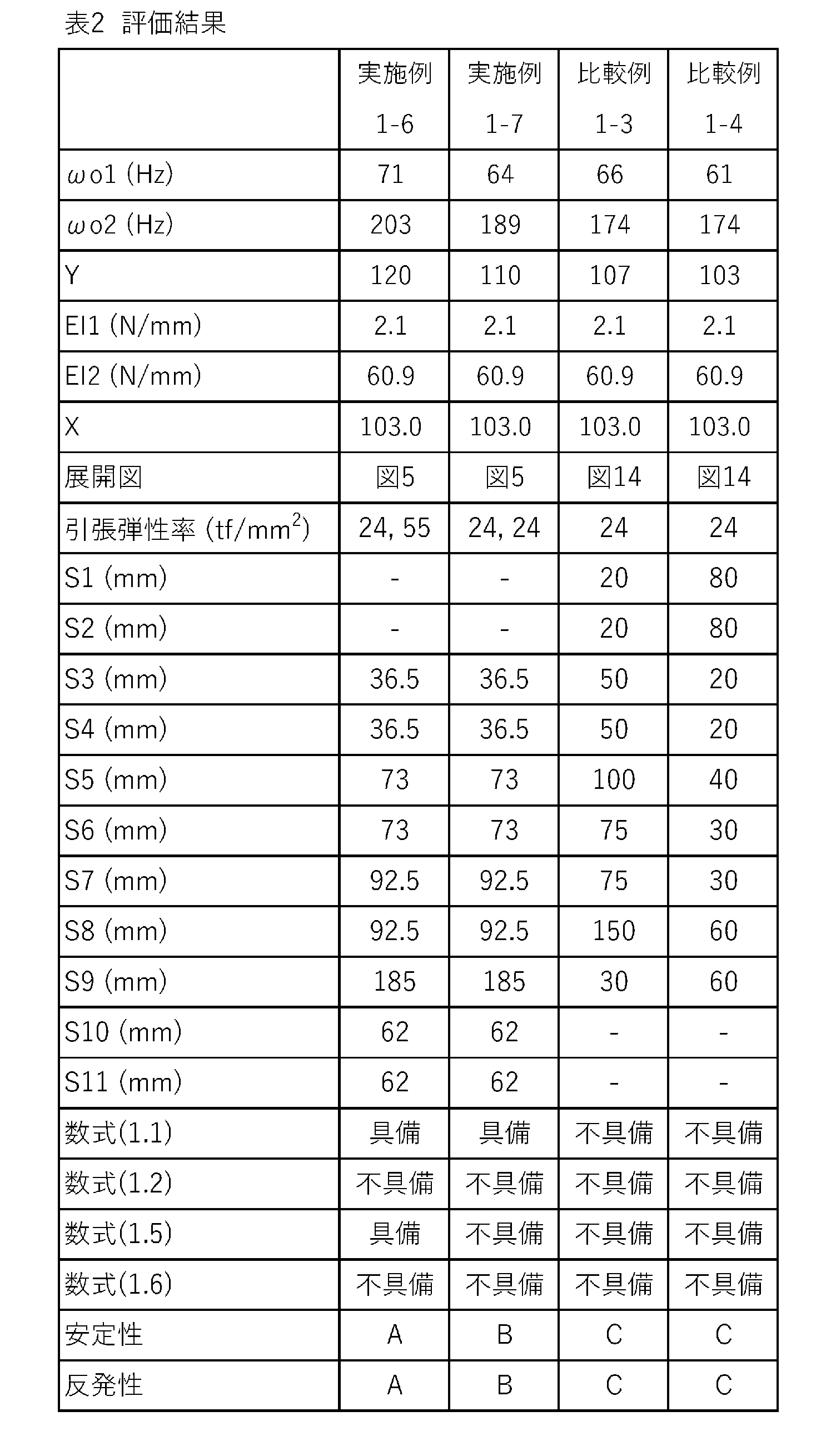

[実験I-3]
硬いバドミントンラケットを好むプレーヤーに、実験I-1と同様の方法で、安定性及び反発性を評価させた。この結果が、下記の表4に示されている。
硬いバドミントンラケットを好むプレーヤーに、実験I-1と同様の方法で、安定性及び反発性を評価させた。この結果が、下記の表4に示されている。
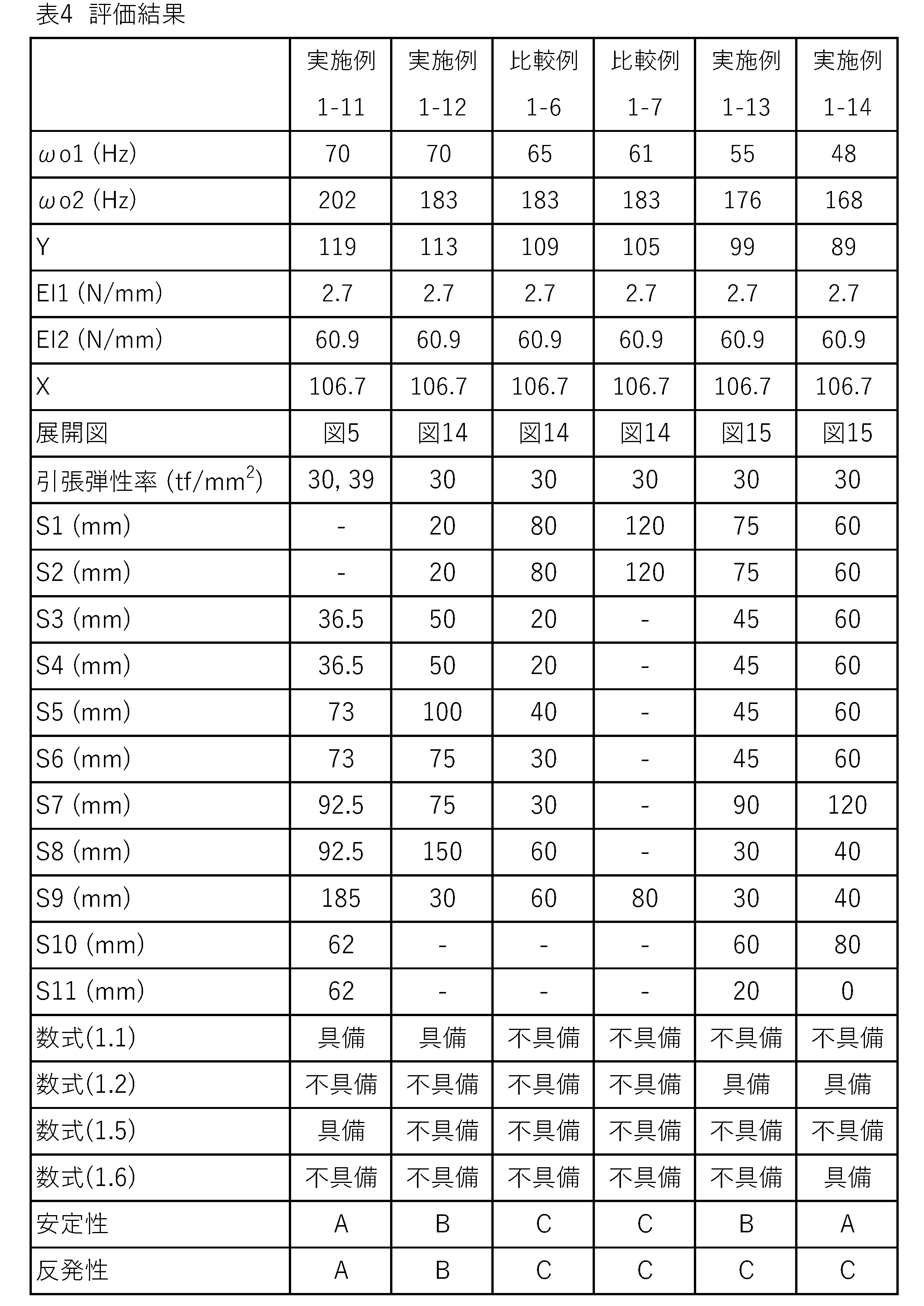
[実験I-4]
極めて硬いバドミントンラケットを好むプレーヤーに、実験I-1と同様の方法で、安定性及び反発性を評価させた。この結果が、下記の表5及び6に示されている。
極めて硬いバドミントンラケットを好むプレーヤーに、実験I-1と同様の方法で、安定性及び反発性を評価させた。この結果が、下記の表5及び6に示されている。
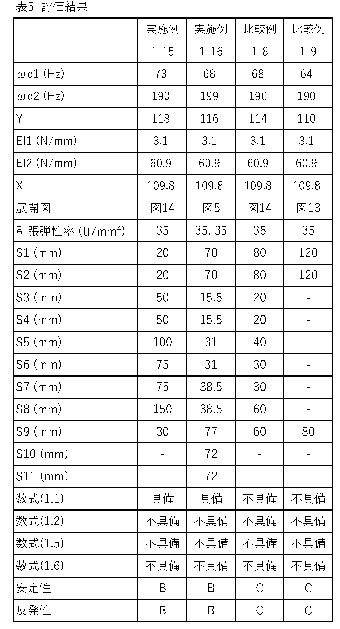
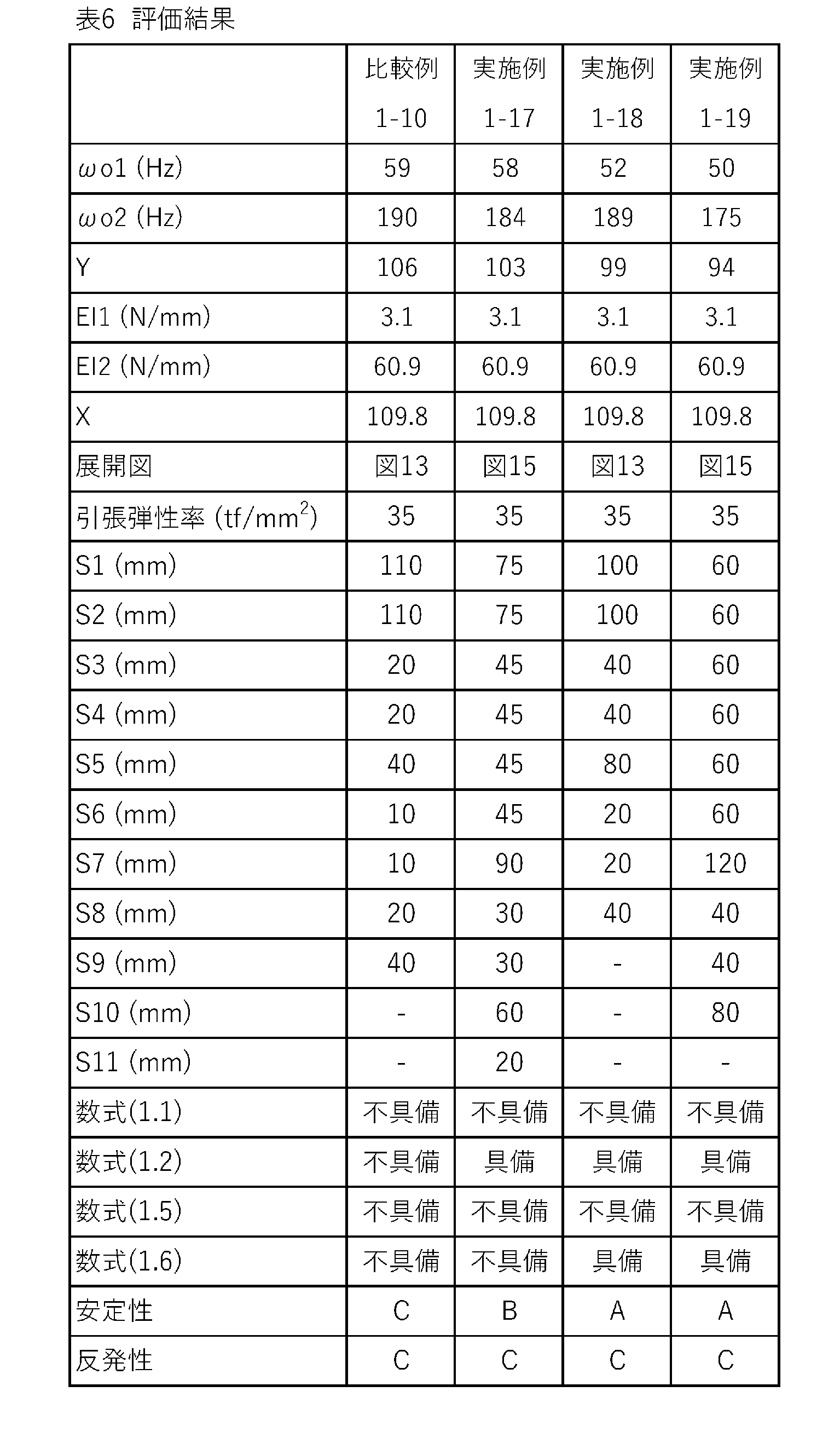
表1-6から明らかな通り、各実施例のバドミントンラケットでは、ドライブにおけるシャトルの弾道が安定している。この評価結果から、このラケットの優位性は明らかである。
[実験II]
[実施例2-1]
図13に示されたプリプレグ構成を有するシャフトを製作した。各プリプレグは、カーボン繊維を含んでいた。第五シートS5、第九シートS9及び第十一シートS11におけるカーボン繊維の引張弾性率は、39tf/mm2であった。残余のシートにおけるカーボン繊維の引張弾性率は、16tf/mm2であった。このシャフトに、標準的な硬さ及び質量を有する市販のバドミントンラケットに使用されているフレーム、ネック、キャップ及びグリップを取り付けて、バドミントンラケットを製作した。このラケットの、面内一次固有振動数ωi1は64Hzであり、面内二次固有振動数ωi2は253Hzであり、片持ち剛性EI1は1.4N/mmであり、側圧剛性EI3は24.5N/mmであった。このラケットの座標は、図18において、符号Prで示されている。
[実施例2-1]
図13に示されたプリプレグ構成を有するシャフトを製作した。各プリプレグは、カーボン繊維を含んでいた。第五シートS5、第九シートS9及び第十一シートS11におけるカーボン繊維の引張弾性率は、39tf/mm2であった。残余のシートにおけるカーボン繊維の引張弾性率は、16tf/mm2であった。このシャフトに、標準的な硬さ及び質量を有する市販のバドミントンラケットに使用されているフレーム、ネック、キャップ及びグリップを取り付けて、バドミントンラケットを製作した。このラケットの、面内一次固有振動数ωi1は64Hzであり、面内二次固有振動数ωi2は253Hzであり、片持ち剛性EI1は1.4N/mmであり、側圧剛性EI3は24.5N/mmであった。このラケットの座標は、図18において、符号Prで示されている。
[実施例2-2から2-21及び比較例2-1から2-11]
プリプレグ構成を表7-14に示される通りとした他は実施例2-1と同様にして、実施例2-2から2-21及び比較例2-1から2-11のバドミントンラケットを得た。これらのラケットのシャフトのためのプリプレグの幅が、下記の表7-14に示されている。これらのラケットの、面内一次固有振動数ωi1、面内二次固有振動数ωi2、片持ち剛性EI1及び側圧剛性EI3が、下記の表7-14に示されている。これらのラケットの値x及びyが、図18に示されている。
プリプレグ構成を表7-14に示される通りとした他は実施例2-1と同様にして、実施例2-2から2-21及び比較例2-1から2-11のバドミントンラケットを得た。これらのラケットのシャフトのためのプリプレグの幅が、下記の表7-14に示されている。これらのラケットの、面内一次固有振動数ωi1、面内二次固有振動数ωi2、片持ち剛性EI1及び側圧剛性EI3が、下記の表7-14に示されている。これらのラケットの値x及びyが、図18に示されている。
[実験II-1]
柔らかいバドミントンラケットを好むプレーヤーに、下記の方法にて、安定性及び反発性を評価させた。
柔らかいバドミントンラケットを好むプレーヤーに、下記の方法にて、安定性及び反発性を評価させた。
[安定性]
発射マシンにて、シャトルを発射した。このシャトルに対してプレーヤーにドリブンクリアを行わせ、シャトルの弾道を撮影した。画像を解析し、ネットの上を通過するシャトルの高さを測定した。20回の測定を行い、高さの標準偏差を求めた。この標準偏差に基づき、ラケットを格付けした。格付けの基準は、以下の通りである。この結果が、下記の表7及び8に示されている。
A:標準偏差が0.18m未満
B:標準偏差が0.18m以上0.25m未満
C:標準偏差が0.25m以上
発射マシンにて、シャトルを発射した。このシャトルに対してプレーヤーにドリブンクリアを行わせ、シャトルの弾道を撮影した。画像を解析し、ネットの上を通過するシャトルの高さを測定した。20回の測定を行い、高さの標準偏差を求めた。この標準偏差に基づき、ラケットを格付けした。格付けの基準は、以下の通りである。この結果が、下記の表7及び8に示されている。
A:標準偏差が0.18m未満
B:標準偏差が0.18m以上0.25m未満
C:標準偏差が0.25m以上
[反発性]
前述の安定性の評価に際し、ネットの上を通過するシャトルの速度を測定した。20回の測定を行い、速度の平均値を求めた。この平均値に基づき、ラケットを格付けした。格付けの基準は、以下の通りである。この結果が、下記の表7及び8に示されている。
A:平均速度が13.0m/s以上
B:平均速度が12.5m/s以上13.0m/s未満
C:平均速度が12.5m/s未満
前述の安定性の評価に際し、ネットの上を通過するシャトルの速度を測定した。20回の測定を行い、速度の平均値を求めた。この平均値に基づき、ラケットを格付けした。格付けの基準は、以下の通りである。この結果が、下記の表7及び8に示されている。
A:平均速度が13.0m/s以上
B:平均速度が12.5m/s以上13.0m/s未満
C:平均速度が12.5m/s未満


[実験II-2]
標準的な硬さのバドミントンラケットを好むプレーヤーに、実験II-1と同様の方法で、安定性及び反発性を評価させた。この結果が、下記の表9及び10に示されている。
標準的な硬さのバドミントンラケットを好むプレーヤーに、実験II-1と同様の方法で、安定性及び反発性を評価させた。この結果が、下記の表9及び10に示されている。

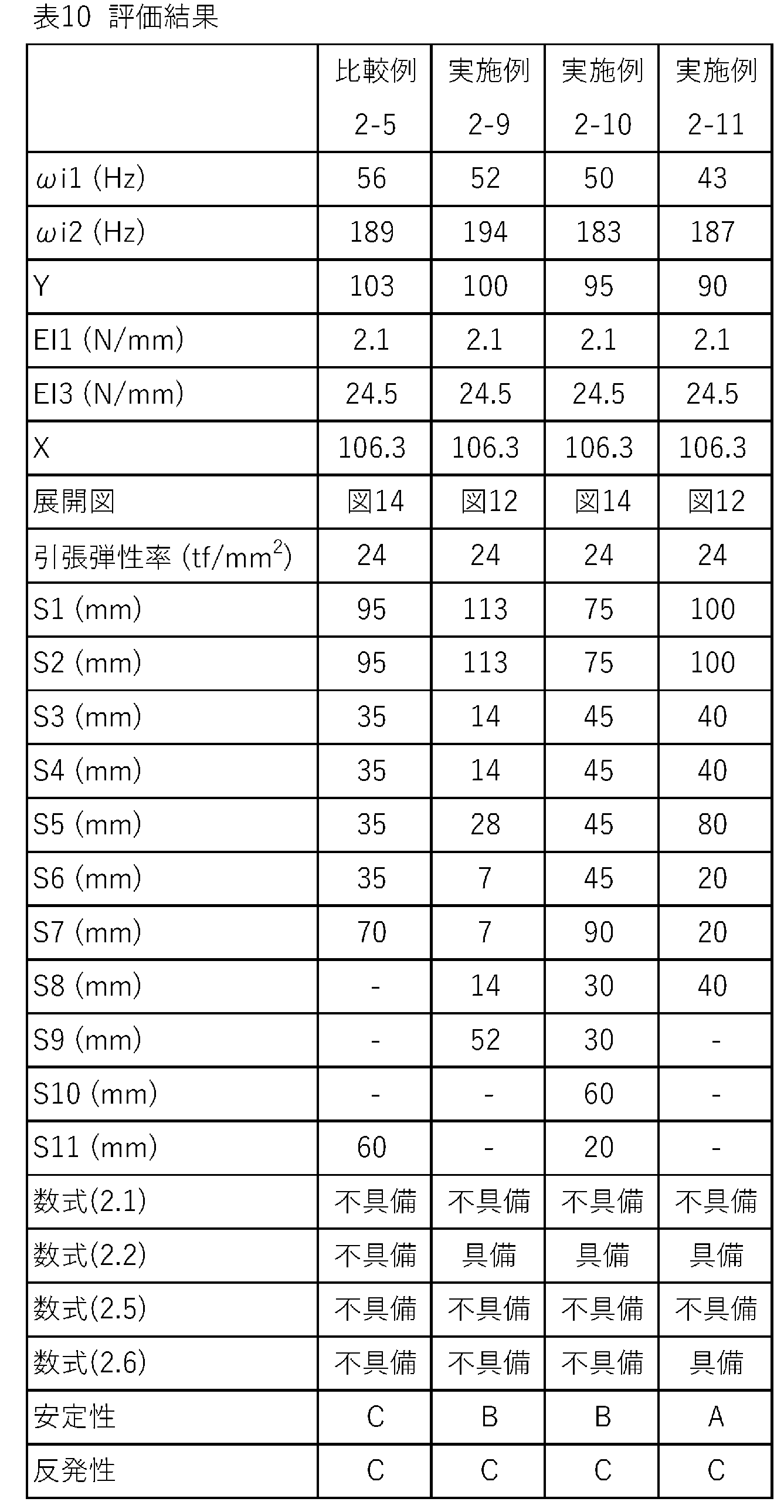
[実験II-3]
硬いバドミントンラケットを好むプレーヤーに、実験II-1と同様の方法で、安定性及び反発性を評価させた。この結果が、下記の表11及び12に示されている。
硬いバドミントンラケットを好むプレーヤーに、実験II-1と同様の方法で、安定性及び反発性を評価させた。この結果が、下記の表11及び12に示されている。
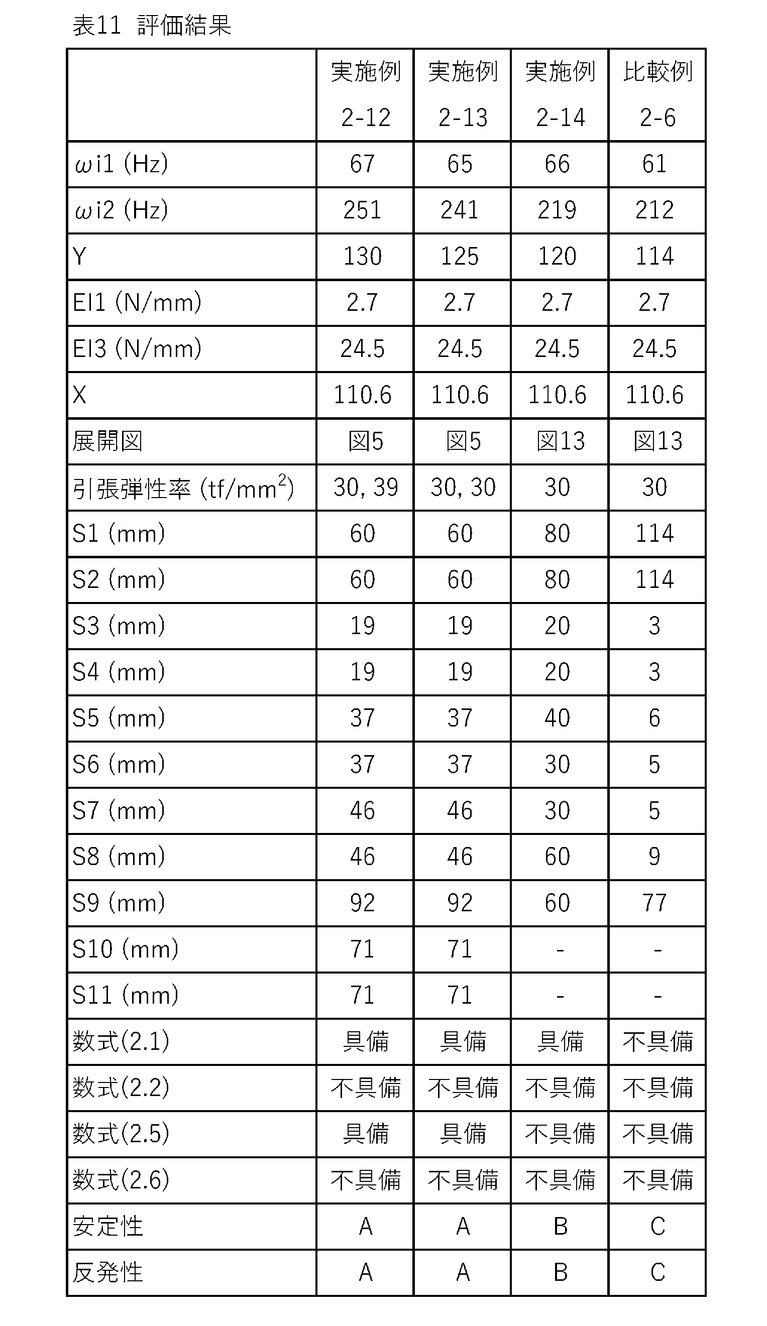
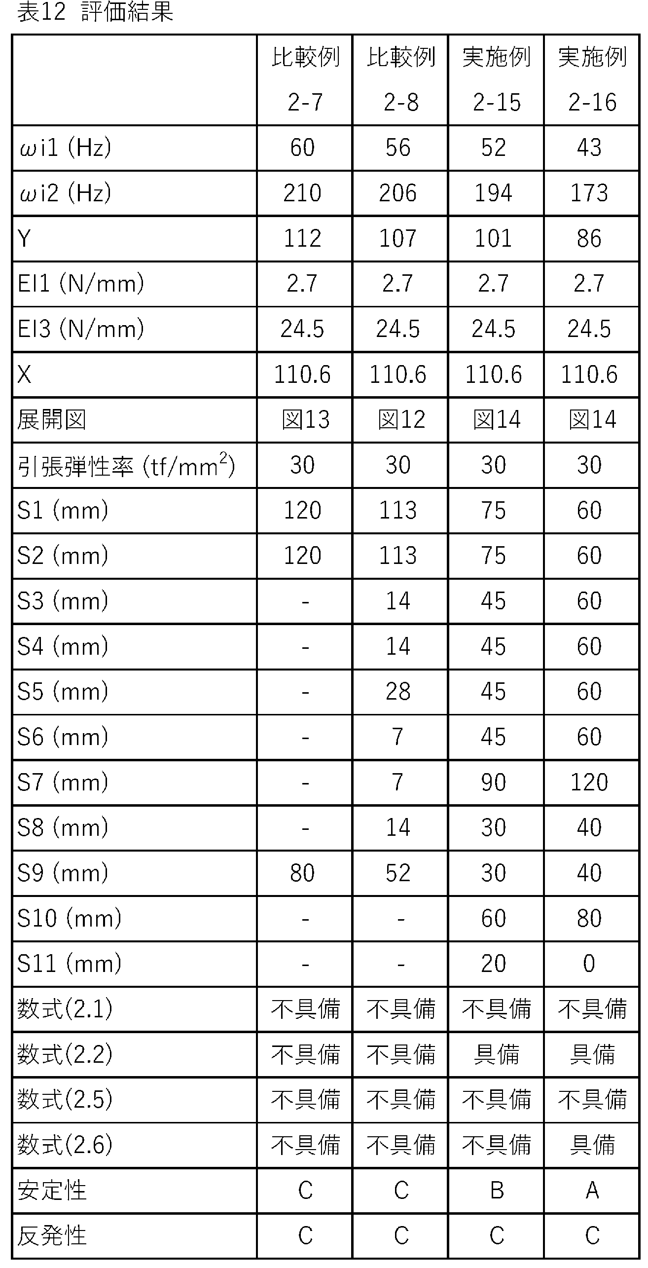
[実験II-4]
極めて硬いバドミントンラケットを好むプレーヤーに、実験II-1と同様の方法で、安定性及び反発性を評価させた。この結果が、下記の表13及び14に示されている。
極めて硬いバドミントンラケットを好むプレーヤーに、実験II-1と同様の方法で、安定性及び反発性を評価させた。この結果が、下記の表13及び14に示されている。
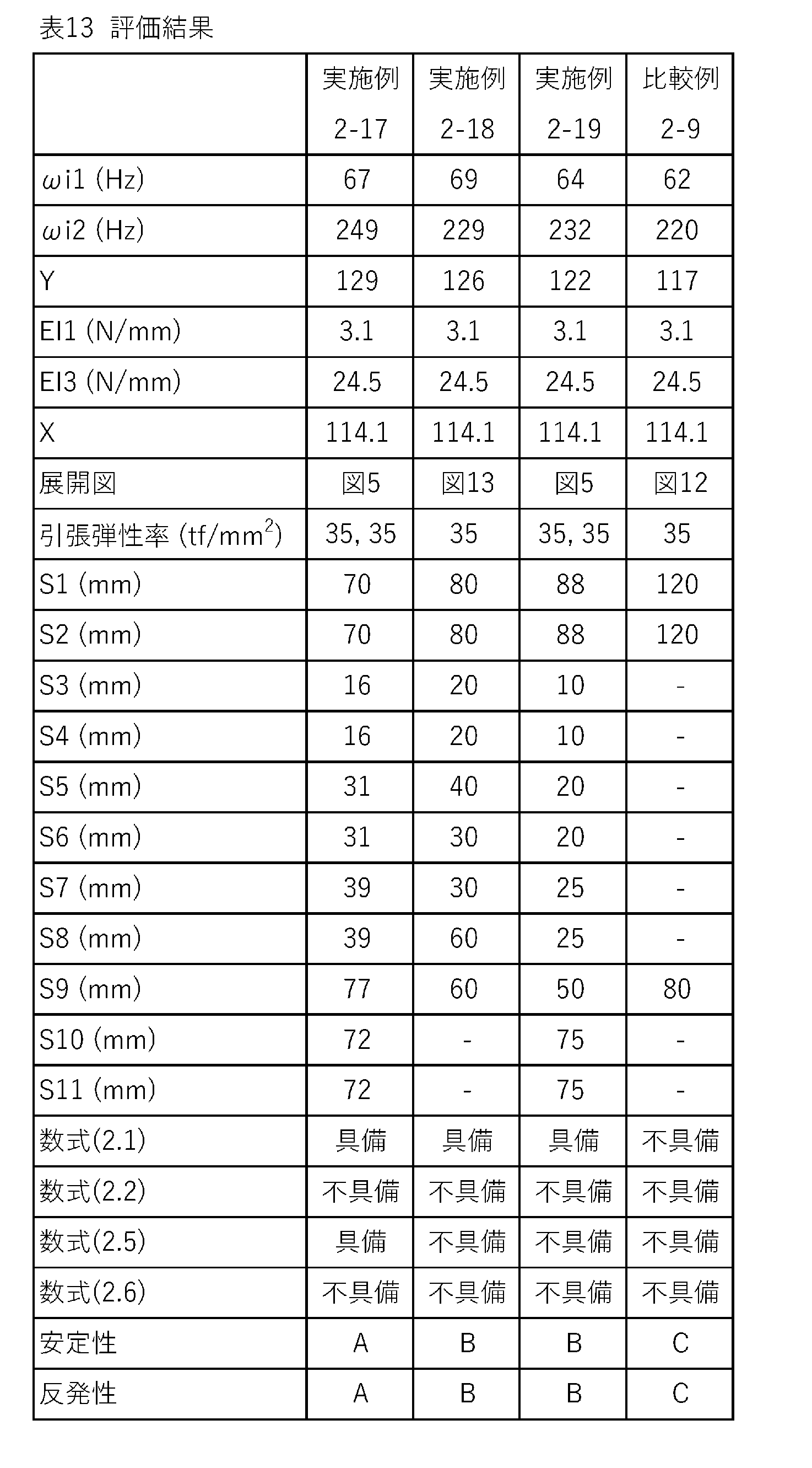
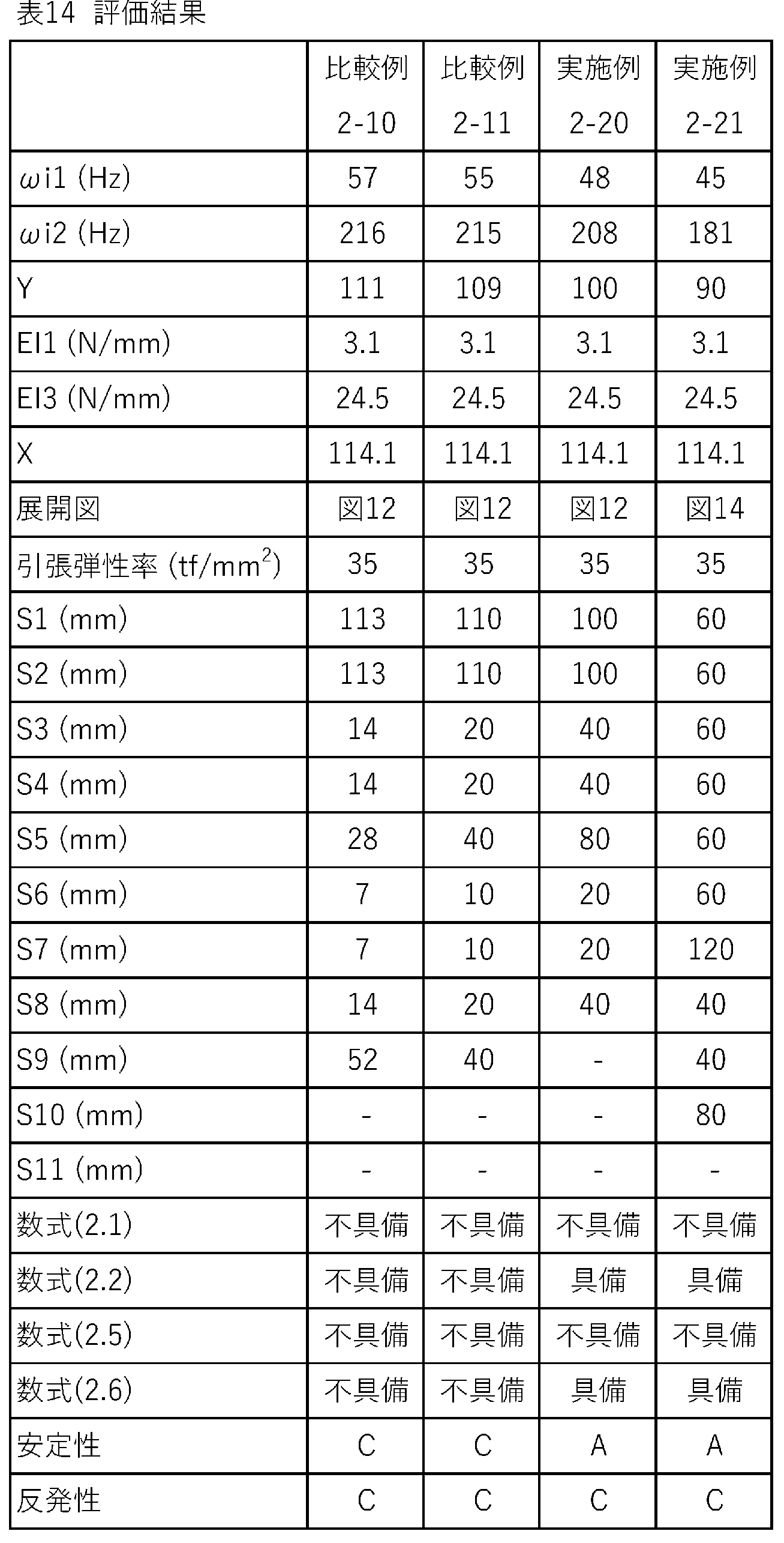
表7-14から明らかな通り、各実施例のバドミントンラケットでは、ドリブンクリアにおけるシャトルの弾道が安定している。この評価結果から、本発明の優位性は明らかである。
[開示項目]
以下の項目は、好ましい実施形態の開示である。
以下の項目は、好ましい実施形態の開示である。
[項目1]
バッドエンド及びチップエンドを有するシャフト、
上記シャフトの、上記バッドエンドの近傍が挿入されるグリップ、
並びに
上記チップエンドの近傍において上記シャフトに取り付けられたフレーム
を備えており、
下記数式(1.1)又は(1.2)を満たすバドミントンラケット。
y ≧x + 5.0 (1.1)
y ≦x - 5.0 (1.2)
(上記数式(1.1)及び(1.2)におけるyは、下記数式(1.3)によって算出される。
y = ( ωo1 * ωo2)1/2 (1.3)
上記数式(1.1)及び(1.2)におけるxは、下記数式(1.4)によって算出される。
x = EI1 * 7.0 + EI2 * 0.28 + 71.0 (1.4)
上記数式(1.3)において、ωo1は上記バドミントンラケットの自由な拘束条件下での固有振動における面外一次固有振動数(Hz)を表し、ωo2は上記バドミントンラケットの自由な拘束条件下での固有振動における面外二次固有振動数(Hz)を表す。上記数式(1.4)において、EI1は上記バドミントンラケットの片持ち剛性(N/mm)を表し、EI2は上記バドミントンラケットの打球面剛性(N/mm)を表す。)
バッドエンド及びチップエンドを有するシャフト、
上記シャフトの、上記バッドエンドの近傍が挿入されるグリップ、
並びに
上記チップエンドの近傍において上記シャフトに取り付けられたフレーム
を備えており、
下記数式(1.1)又は(1.2)を満たすバドミントンラケット。
y ≧x + 5.0 (1.1)
y ≦x - 5.0 (1.2)
(上記数式(1.1)及び(1.2)におけるyは、下記数式(1.3)によって算出される。
y = ( ωo1 * ωo2)1/2 (1.3)
上記数式(1.1)及び(1.2)におけるxは、下記数式(1.4)によって算出される。
x = EI1 * 7.0 + EI2 * 0.28 + 71.0 (1.4)
上記数式(1.3)において、ωo1は上記バドミントンラケットの自由な拘束条件下での固有振動における面外一次固有振動数(Hz)を表し、ωo2は上記バドミントンラケットの自由な拘束条件下での固有振動における面外二次固有振動数(Hz)を表す。上記数式(1.4)において、EI1は上記バドミントンラケットの片持ち剛性(N/mm)を表し、EI2は上記バドミントンラケットの打球面剛性(N/mm)を表す。)
[項目2]
下記数式(1.5)を満たす項目1に記載のバドミントンラケット。
y ≧x + 11.0 (1.5)
下記数式(1.5)を満たす項目1に記載のバドミントンラケット。
y ≧x + 11.0 (1.5)
[項目3]
下記数式(1.6)を満たす項目1に記載のバドミントンラケット。
y ≦x - 10.5 (1.6)
下記数式(1.6)を満たす項目1に記載のバドミントンラケット。
y ≦x - 10.5 (1.6)
[項目4]
バッドエンド及びチップエンドを有するシャフト、
上記シャフトの、上記バッドエンドの近傍が挿入されるグリップ、
並びに
上記チップエンドの近傍において上記シャフトに取り付けられたフレーム
を備えており、
下記数式(2.1)又は(2.2)を満たすバドミントンラケット。
y ≧x + 5.0 (2.1)
y ≦x - 6.0 (2.2)
(上記数式(2.1)及び(2.2)におけるyは、下記数式(2.3)によって算出される。
y = ( ωi1 * ωi2)1/2 (2.3)
上記数式(2.1)及び(2.2)におけるxは、下記数式(2.4)によって算出される。
x = EI1 * 8.0 + EI3 * 0.46 + 78.0 (2.4)
上記数式(2.3)において、ωi1は上記バドミントンラケットの固有振動における面内一次固有振動数(Hz)を表し、ωi2は上記バドミントンラケットの固有振動における面内二次固有振動数(Hz)を表す。上記数式(2.4)において、EI1は上記バドミントンラケットの片持ち剛性(N/mm)を表し、EI3は上記バドミントンラケットの側圧剛性(N/mm)を表す。)
バッドエンド及びチップエンドを有するシャフト、
上記シャフトの、上記バッドエンドの近傍が挿入されるグリップ、
並びに
上記チップエンドの近傍において上記シャフトに取り付けられたフレーム
を備えており、
下記数式(2.1)又は(2.2)を満たすバドミントンラケット。
y ≧x + 5.0 (2.1)
y ≦x - 6.0 (2.2)
(上記数式(2.1)及び(2.2)におけるyは、下記数式(2.3)によって算出される。
y = ( ωi1 * ωi2)1/2 (2.3)
上記数式(2.1)及び(2.2)におけるxは、下記数式(2.4)によって算出される。
x = EI1 * 8.0 + EI3 * 0.46 + 78.0 (2.4)
上記数式(2.3)において、ωi1は上記バドミントンラケットの固有振動における面内一次固有振動数(Hz)を表し、ωi2は上記バドミントンラケットの固有振動における面内二次固有振動数(Hz)を表す。上記数式(2.4)において、EI1は上記バドミントンラケットの片持ち剛性(N/mm)を表し、EI3は上記バドミントンラケットの側圧剛性(N/mm)を表す。)
[項目5]
下記数式(2.5)を満たす項目4に記載のバドミントンラケット。
y ≧x + 14.0 (2.5)
下記数式(2.5)を満たす項目4に記載のバドミントンラケット。
y ≧x + 14.0 (2.5)
[項目6]
下記数式(2.6)を満たす項目4に記載のバドミントンラケット。
y ≦x - 14.0 (2.6)
下記数式(2.6)を満たす項目4に記載のバドミントンラケット。
y ≦x - 14.0 (2.6)
以上説明されたバドミントンラケットは、ドライブ又はドリブンクリアを多用するスタイルのプレーヤーに適している。このラケットは、打点がセンター近傍である他のショットを多用するスタイルのプレーヤーにも、適している。
2、102・・・バドミントンラケット
4、104・・・シャフト
6、106・・・フレーム
8・・・ネック
10、110・・・グリップ
12・・・ストリング
14・・・バッド部
16・・・ミドル部
18・・・チップ部
20・・・バッドエンド
22・・・チップエンド
24・・・トップ
26・・・ボトム
28・・・横スレッド
30・・・縦スレッド
32・・・フェース
34・・・露出部
38・・・加速度ピックアップ
42・・・第一ブロック
44・・・第二ブロック
46・・・圧子
48・・・当接面
50・・・第一バー
52・・・第二バー
54・・・当接面
S1・・・第一シート
S2・・・第二シート
S3・・・第三シート
S4・・・第四シート
S5・・・第五シート
S6・・・第六シート
S7・・・第七シート
S8・・・第八シート
S9・・・第九シート
4、104・・・シャフト
6、106・・・フレーム
8・・・ネック
10、110・・・グリップ
12・・・ストリング
14・・・バッド部
16・・・ミドル部
18・・・チップ部
20・・・バッドエンド
22・・・チップエンド
24・・・トップ
26・・・ボトム
28・・・横スレッド
30・・・縦スレッド
32・・・フェース
34・・・露出部
38・・・加速度ピックアップ
42・・・第一ブロック
44・・・第二ブロック
46・・・圧子
48・・・当接面
50・・・第一バー
52・・・第二バー
54・・・当接面
S1・・・第一シート
S2・・・第二シート
S3・・・第三シート
S4・・・第四シート
S5・・・第五シート
S6・・・第六シート
S7・・・第七シート
S8・・・第八シート
S9・・・第九シート
Claims (6)
- バッドエンド及びチップエンドを有するシャフト、
上記シャフトの、上記バッドエンドの近傍が挿入されるグリップ、
並びに
上記チップエンドの近傍において上記シャフトに取り付けられたフレーム
を備えており、
下記数式(1.1)又は(1.2)を満たすバドミントンラケット。
y ≧x + 5.0 (1.1)
y ≦x - 5.0 (1.2)
(上記数式(1.1)及び(1.2)におけるyは、下記数式(1.3)によって算出される。
y = ( ωo1 * ωo2)1/2 (1.3)
上記数式(1.1)及び(1.2)におけるxは、下記数式(1.4)によって算出される。
x = EI1 * 7.0 + EI2 * 0.28 + 71.0 (1.4)
上記数式(1.3)において、ωo1は上記バドミントンラケットの自由な拘束条件下での固有振動における面外一次固有振動数(Hz)を表し、ωo2は上記バドミントンラケットの自由な拘束条件下での固有振動における面外二次固有振動数(Hz)を表す。上記数式(1.4)において、EI1は上記バドミントンラケットの片持ち剛性(N/mm)を表し、EI2は上記バドミントンラケットの打球面剛性(N/mm)を表す。) - 下記数式(1.5)を満たす請求項1に記載のバドミントンラケット。
y ≧x + 11.0 (1.5) - 下記数式(1.6)を満たす請求項1に記載のバドミントンラケット。
y ≦x - 10.5 (1.6) - バッドエンド及びチップエンドを有するシャフト、
上記シャフトの、上記バッドエンドの近傍が挿入されるグリップ、
並びに
上記チップエンドの近傍において上記シャフトに取り付けられたフレーム
を備えており、
下記数式(2.1)又は(2.2)を満たすバドミントンラケット。
y ≧x + 5.0 (2.1)
y ≦x - 6.0 (2.2)
(上記数式(2.1)及び(2.2)におけるyは、下記数式(2.3)によって算出される。
y = ( ωi1 * ωi2)1/2 (2.3)
上記数式(2.1)及び(2.2)におけるxは、下記数式(2.4)によって算出される。
x = EI1 * 8.0 + EI3 * 0.46 + 78.0 (2.4)
上記数式(2.3)において、ωi1は上記バドミントンラケットの固有振動における面内一次固有振動数(Hz)を表し、ωi2は上記バドミントンラケットの固有振動における面内二次固有振動数(Hz)を表す。上記数式(2.4)において、EI1は上記バドミントンラケットの片持ち剛性(N/mm)を表し、EI3は上記バドミントンラケットの側圧剛性(N/mm)を表す。) - 下記数式(2.5)を満たす請求項4に記載のバドミントンラケット。
y ≧x + 14.0 (2.5) - 下記数式(2.6)を満たす請求項4に記載のバドミントンラケット。
y ≦x - 14.0 (2.6)
Priority Applications (1)
| Application Number | Priority Date | Filing Date | Title |
|---|---|---|---|
| CN202180087952.XA CN116669821B (zh) | 2020-12-28 | 2021-12-10 | 羽毛球拍 |
Applications Claiming Priority (4)
| Application Number | Priority Date | Filing Date | Title |
|---|---|---|---|
| JP2020218385A JP7505405B2 (ja) | 2020-12-28 | 2020-12-28 | バドミントンラケット |
| JP2020-218384 | 2020-12-28 | ||
| JP2020218384A JP7543906B2 (ja) | 2020-12-28 | 2020-12-28 | バドミントンラケット |
| JP2020-218385 | 2020-12-28 |
Publications (1)
| Publication Number | Publication Date |
|---|---|
| WO2022145201A1 true WO2022145201A1 (ja) | 2022-07-07 |
Family
ID=82260437
Family Applications (1)
| Application Number | Title | Priority Date | Filing Date |
|---|---|---|---|
| PCT/JP2021/045544 Ceased WO2022145201A1 (ja) | 2020-12-28 | 2021-12-10 | バドミントンラケット |
Country Status (2)
| Country | Link |
|---|---|
| CN (1) | CN116669821B (ja) |
| WO (1) | WO2022145201A1 (ja) |
Citations (2)
| Publication number | Priority date | Publication date | Assignee | Title |
|---|---|---|---|---|
| JP2005027887A (ja) * | 2003-07-04 | 2005-02-03 | Sumitomo Rubber Ind Ltd | ラケットフレーム |
| JP2005177442A (ja) * | 2003-11-27 | 2005-07-07 | Sumitomo Rubber Ind Ltd | ラケットフレーム |
Family Cites Families (2)
| Publication number | Priority date | Publication date | Assignee | Title |
|---|---|---|---|---|
| WO2015143306A1 (en) * | 2014-03-20 | 2015-09-24 | Bruce Wright | Articulated butt end improvement on handheld rackets, bats and clubs |
| CN105092193A (zh) * | 2015-07-21 | 2015-11-25 | 南京林业大学 | 一种羽毛球拍拍杆的软硬度测试方法 |
-
2021
- 2021-12-10 CN CN202180087952.XA patent/CN116669821B/zh active Active
- 2021-12-10 WO PCT/JP2021/045544 patent/WO2022145201A1/ja not_active Ceased
Patent Citations (2)
| Publication number | Priority date | Publication date | Assignee | Title |
|---|---|---|---|---|
| JP2005027887A (ja) * | 2003-07-04 | 2005-02-03 | Sumitomo Rubber Ind Ltd | ラケットフレーム |
| JP2005177442A (ja) * | 2003-11-27 | 2005-07-07 | Sumitomo Rubber Ind Ltd | ラケットフレーム |
Also Published As
| Publication number | Publication date |
|---|---|
| CN116669821B (zh) | 2026-03-31 |
| CN116669821A (zh) | 2023-08-29 |
Similar Documents
| Publication | Publication Date | Title |
|---|---|---|
| US7500922B2 (en) | Golf club shaft | |
| WO2022145201A1 (ja) | バドミントンラケット | |
| JP7543906B2 (ja) | バドミントンラケット | |
| JP7505405B2 (ja) | バドミントンラケット | |
| EP4545155A1 (en) | Racket | |
| WO2022145199A1 (ja) | バドミントンラケット | |
| JP7703967B2 (ja) | バドミントンラケット | |
| JP7703966B2 (ja) | バドミントンラケット | |
| WO2022145200A1 (ja) | バドミントンラケット | |
| JP2022103631A (ja) | バドミントンラケット | |
| JP7505404B2 (ja) | バドミントンラケット | |
| JP2022103630A (ja) | バドミントンラケット | |
| JP2022103632A (ja) | バドミントンラケット | |
| US7074142B2 (en) | Racket frame | |
| JP2023044829A (ja) | バドミントンラケット | |
| JP4778216B2 (ja) | ラケット | |
| JP2023044828A (ja) | バドミントンラケット | |
| JP3820215B2 (ja) | テニスラケット | |
| JP3738276B2 (ja) | テニスラケットフレーム | |
| JP7748665B2 (ja) | ラケット | |
| CN121016154A (zh) | 球拍 | |
| US20250367510A1 (en) | Racket | |
| JP7459551B2 (ja) | バドミントンラケット | |
| JP4444429B2 (ja) | 軟式テニス用ラケットフレーム | |
| EP4098334A1 (en) | Badminton racket |
Legal Events
| Date | Code | Title | Description |
|---|---|---|---|
| 121 | Ep: the epo has been informed by wipo that ep was designated in this application |
Ref document number: 21915062 Country of ref document: EP Kind code of ref document: A1 |
|
| WWE | Wipo information: entry into national phase |
Ref document number: 202180087952.X Country of ref document: CN |
|
| NENP | Non-entry into the national phase |
Ref country code: DE |
|
| 122 | Ep: pct application non-entry in european phase |
Ref document number: 21915062 Country of ref document: EP Kind code of ref document: A1 |