WO2022145148A1 - Corps de poupée et mécanisme de rotation - Google Patents
Corps de poupée et mécanisme de rotation Download PDFInfo
- Publication number
- WO2022145148A1 WO2022145148A1 PCT/JP2021/042735 JP2021042735W WO2022145148A1 WO 2022145148 A1 WO2022145148 A1 WO 2022145148A1 JP 2021042735 W JP2021042735 W JP 2021042735W WO 2022145148 A1 WO2022145148 A1 WO 2022145148A1
- Authority
- WO
- WIPO (PCT)
- Prior art keywords
- doll
- doll body
- armor
- main body
- decorative
- Prior art date
Links
- 230000007246 mechanism Effects 0.000 title claims abstract description 17
- 210000001624 hip Anatomy 0.000 description 26
- 210000002414 leg Anatomy 0.000 description 17
- 210000003414 extremity Anatomy 0.000 description 5
- 210000001503 joint Anatomy 0.000 description 4
- 230000000694 effects Effects 0.000 description 3
- 210000004394 hip joint Anatomy 0.000 description 3
- 230000004048 modification Effects 0.000 description 3
- 238000012986 modification Methods 0.000 description 3
- 241001465754 Metazoa Species 0.000 description 2
- 238000007796 conventional method Methods 0.000 description 2
- 238000005034 decoration Methods 0.000 description 2
- 210000000689 upper leg Anatomy 0.000 description 2
- 241000086550 Dinosauria Species 0.000 description 1
- 241000238631 Hexapoda Species 0.000 description 1
- 210000004705 lumbosacral region Anatomy 0.000 description 1
Images


Classifications
-
- A—HUMAN NECESSITIES
- A63—SPORTS; GAMES; AMUSEMENTS
- A63H—TOYS, e.g. TOPS, DOLLS, HOOPS OR BUILDING BLOCKS
- A63H3/00—Dolls
- A63H3/36—Details; Accessories
-
- A—HUMAN NECESSITIES
- A63—SPORTS; GAMES; AMUSEMENTS
- A63H—TOYS, e.g. TOPS, DOLLS, HOOPS OR BUILDING BLOCKS
- A63H3/00—Dolls
- A63H3/36—Details; Accessories
- A63H3/46—Connections for limbs
-
- A—HUMAN NECESSITIES
- A63—SPORTS; GAMES; AMUSEMENTS
- A63H—TOYS, e.g. TOPS, DOLLS, HOOPS OR BUILDING BLOCKS
- A63H3/00—Dolls
- A63H3/36—Details; Accessories
- A63H3/48—Mounting of parts within dolls, e.g. automatic eyes or parts for animation
Definitions
- the present invention relates to a doll body and a rotation mechanism.
- Doll toys include various joints and moving parts in order to realize movements and poses that are close to the movements of humans and animals. Various poses can be realized by these mechanisms. Further, in addition to the main body that realizes the above operation, the doll body is further equipped with armor, armor, a skirt, and the like (hereinafter, these are collectively referred to as a decorative part). Since these decorative portions are attached in close contact with the main body, the range of motion of the main body may be narrowed. Therefore, it is desirable that such a decorative portion operates in conjunction with the main body, for example, an arm portion or a leg portion. It was
- Patent Document 1 proposes a doll body in which the movement of armor according to the movement of a limb is complicated and the movement of the armor is made realistic.
- armor covering a side different from the main body side is arranged on a limb connected to the main body via a joint mechanism, and the armor rotates with the upper body via a ball joint. It is freely connected and is further connected to the limb via a rotatable connecting part. This realizes armor that moves according to the movement of the limbs.
- the armor provided along the limb or the arm follows the movement of the armor.
- the decorative part naturally includes those provided along the main body and those not along the main body.
- the armor on the front of the waist is often not provided along the main body, and it is difficult to apply the above-mentioned conventional technique.
- even in such armor on the front of the waist it is provided in the range of motion of the legs, and there is a possibility that the movement is restricted. It was
- the present invention provides, for example, in a doll body, a mechanism for appropriately providing a decorative portion without limiting the range of motion of the doll body body, and realizing more flexible movements and various poses.
- the present invention is, for example, a doll body via a main body portion of the doll body, each connecting member whose one end is connected to each connecting portion provided on the main body portion, and each connecting member. It is a decorative portion that is rotatably mounted on the main body portion, and is characterized by including the decorative portion having each connecting portion to which the other ends of the respective connecting members are connected. It was
- the present invention is, for example, a rotation mechanism of a decorative portion attached to the main body portion of a doll body, and each connecting member is connected to each first connecting portion having a spherical shape provided in the main body portion.
- the other end of each connecting member is rotatable with respect to the first rotating portion whose one end is rotatably supported and the second connecting portion having a spherical shape provided in the decorative portion. It is characterized in that it is provided with a second rotating portion that is pivotally supported by the.
- the present invention it is possible to appropriately provide a decorative portion without limiting the range of motion of the doll body body, and to realize more flexible movements and various poses.
- FIG. 1 shows the front view of the appearance of the doll body 100.
- FIG. 1A shows the front view of the appearance of the doll body 100, and
- FIG. 1B shows the appearance side surface of the doll body 100. It was
- the doll body (doll toy) 100 includes a head portion 101, a body portion 102, an arm portion 103, a waist portion 104, and a leg portion 105 that constitute the main body portion.
- the head 101 is connected to the body portion 102.
- An arm portion 103 including a right arm and a left arm is further connected to the body portion 102, and a waist portion 104 is connected to the lower part.
- a leg 105 including a right foot and a left foot is connected to the waist 104.
- the upper body including the head 101, the torso 102, and the arms 103 will be referred to as an upper body.
- the waist 104 is located in the area shown by the dotted line in FIG.
- the waist portion 104 may be provided with a decorative portion such as a weapon, armor, a skirt, or the like of the doll body 100 on the outside.
- the armor connected to the waist portion 104 will be described as an example of the decorative portion, but the present invention is not intended to be limited, and other types of decorative portions may be used, and other doll bodies may be used. It may be connected to a position. It was
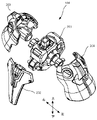
- FIG. 2 shows an exploded view of a state in which the side member of the lumbar portion 104 and the armor mounted in front of the lumbar portion 104 are removed from the central member of the lumbar region 104.
- the up / down, left / right, and front / back arrows indicate the orientation of the doll in the figure, and the same applies to the other drawings. It was
- the lumbar portion 104 includes a lumbar center member 201 and lumbar side members 203 and 204. Further, the armor 202 is rotatably attached to the lumbar portion 104 with respect to the lumbar portion center member 201.
- the body portion 102 of the doll body 100 is attached to the waist center member 201 from above, and functions as a waist joint of the doll body 100.
- the lumbar side members 203 and 204 are attached from both sides of the lumbar center member 201, respectively.
- the legs 105 of the doll body 100 are connected to the waist side members 203 and 204, respectively, and function as the hip joint of the doll body 100.
- the detailed connection configuration between the lumbar center member 201 and the armor 202 will be described later with reference to FIG.
- the armor 202 is attached to the front of the waist of the doll body 100 as the decorative portion according to the present embodiment.
- the present invention can be applied even when the doll body 100 is mounted at another position.
- it may be provided behind the waist.
- it may be provided on the outside of the body portion 102 of the doll body so as to follow the arm portion 103 of the doll body 100 and operate. It was
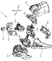
- FIG. 3 shows an exploded view of each member constituting the lumbar center member 201 from the exploded view of FIG. It was
- the lumbar center member 201 includes a foundation member 201a, a shaft member 201b, cover members 201c, 201d, side members 201e, 201f, and a fitting 201g.
- a spherical connecting portion (ball) is fitted into the opening of the base member 201a, and the shaft portion is rotatably mounted back and forth and left and right.
- a body portion 102 is attached to the shaft member 201b.
- the body portion 102 is rotatably attached to the shaft member 201b to the left and right, and can also be rotated following the operation of the shaft member 201b, so that the body portion 102 can be rotated on multiple axes. It was
- the cover members 201c and 201d are mounted so as to cover the foundation member 201a and the shaft member 201b, are fitted to each other, and are fixed by mounting the fitting 201g from above.
- the side members 201e and 201f are mounted so as to cover the foundation member 201a from both the left and right sides of the foundation member 201a, and are fitted and fixed to each other.
- the side members 201e and 201f are provided with openings, respectively, and cylindrical portions (shaft members 406a and 406b) provided on both sides of the base member 201a penetrate through the side members 201e and 201f, respectively.
- Waist side members 203 and 204 are rotatably attached to the cylindrical portion, respectively.
- the waist side member 203 to which each leg 105 is mounted can be rotated in the front-rear direction in the doll body 100, and the leg 105 is also rotatably mounted to the waist side member 203. Therefore, various movements and poses can be realized.
- the thigh (not shown) may be rotatable in the left-right direction of the doll body 100, and in this case, the leg 105 can be rotated inward or outward, and more movements can be performed. You can pose.
- the armor 202 since the armor 202 is attached to the front of the waist, the range of motion of the leg 105 may be narrowed depending on the operating range of the armor 202. Therefore, according to the present invention, there is provided a mechanism for appropriately providing a decorative portion without limiting the range of motion of the doll body to realize more flexible movements and various poses. A detailed configuration will be described with reference to FIGS. 4 to 6. It was
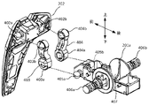
- FIG. 4 is an exploded perspective view of the foundation member 201a, the armor 202, and the connecting members 403 and 404 as viewed from the left rear side of the doll body 100. It was
- the lumbar foundation member 201a is provided with spherical connecting portions (balls) 405a and 405b on the front side surfaces, respectively. Further, on the side surface of the opening 407 into which the shaft member 201a is fitted, cylindrical shaft members 406a and 406b to which the waist side members 203 and 204 are rotatably mounted are provided. Further, the armor 202 is provided with spherical connecting portions 402a and 402b on the back surface, respectively. It was
- Each of the connecting members 403 and 404 is provided with one end 403a and 404a and the other end 403b and 404b.
- One ends 403a and 404a are formed with recesses for fitting spherical connecting portions 405a and 405b provided in the lumbar foundation member 201a, and the connecting members 403 and 404 are rotated in the front-rear direction with respect to the doll body body. It can be pivotally supported as much as possible.
- the recess forms a spherical opening that can accept the spherical connecting portions 405a and 405b.
- the connecting members 403 and 404 are in multiple directions (omnidirectional), although there are spatial restrictions due to contact with other members and the like. It can rotate within a predetermined range. It was
- the other ends 403b and 404b are formed with recesses in which the spherical connecting portions (balls) 402a and 402b provided in the armor 202 are fitted, and the armor 202 can rotate in the front-rear direction with respect to the doll body body.
- the connecting members 403 and 404 can be pivotally supported.
- the recess forms a spherical opening that can accept the spherical connecting portions 402a and 402b.
- the armor 202 and the connecting members 403 and 404 are also ball joints, the armor 202 is predetermined with respect to the connecting member 403 in multiple directions, although there are spatial restrictions due to contact with other members and the like. It is rotatable within the range of. It was
- the armor 202 is not directly attached to the doll body body, but is attached via the connecting members 403 and 404, so that the armor 202 can operate independently of the doll body body. And the degree of freedom can be given by the operation.
- the connecting portions 405a and 405b of the doll body to which the connecting members 403 and 404 are connected and the connecting portions 402a and 402b of the armor 202 are formed in a spherical shape, respectively, so that they rotate in multiple directions. It becomes possible. That is, the connecting members 403 and 404 can rotate in all directions at each of the connecting portions unless restricted by other members, whereby the armor 202 can perform various movements and the leg portion 105 operates.
- the armor 202 which is the decorative portion according to the present embodiment, has two stages of rotation between the connecting portion with the doll body body (first rotating portion) and the connecting portion with the armor (second rotating portion). For example, after the first rotating portion is rotated, the second rotating portion can be further rotated, and the range of motion can be further expanded. In the following, a detailed rotation mechanism will be described with reference to FIGS. 5 and 6.
- the armor 202 is attached to the doll body 100 by two arms (connecting members 403 and 404).
- the connecting member will enter and the armor will be in a floating state with respect to the doll body.
- the armor can be attached in close contact with the doll body body.
- the armor can be attached to the doll body more firmly. If it is possible to avoid spatial restrictions, it is also possible to pivotally support the armor with one connecting member. The form in this case will be described later as a modification. It was
- FIGS. 5 and 6 a rotation mechanism in which the armor 202, which is the decorative portion according to the present embodiment, rotates in the front-rear direction with respect to the doll body 100 will be described.
- 5 (a) to 5 (d) show side views of the lumbar foundation member 201a, the armor 202, and the connecting member 403 as viewed from the right side of the doll body 100.
- the connecting member 403 will be described here, the description of the connecting member 404 will be omitted because the movement is the same. It was
- One end 403a of the connecting member 403 is fitted into the connecting portion 405a of the lumbar foundation member 201a and rotatably supported by a shaft to form a first rotating portion.
- the connecting member 403 can be rotated in the front-rear direction of the doll body 100 by the first rotating portion. Accordingly, the armor 202 connected to the connecting member 403 also follows and moves in the front-rear direction with respect to the doll body 100. It was
- the other end 403b of the connecting member 403 is fitted into the connecting portion 402a of the armor 202 and rotatably supported by the shaft to form a second rotating portion.
- the armor 202 can be rotated in the front-rear direction of the doll body 100 by the second rotating portion. It was
- the armor 202 which is the decorative portion according to the present embodiment, can be rotated in two stages by the first rotating portion and the second rotating portion, and can have a wider range of motion. It was
- FIG. 6 a rotation mechanism in which the armor 202, which is the decorative portion according to the present embodiment, rotates in the left-right direction with respect to the doll body 100 will be described.
- 6 (a) to 6 (c) show a plan view of the lumbar foundation member 201a, the armor 202, and the connecting member 403 as viewed from above of the doll body 100. It was
- the connecting members 403 and 404 have one ends 403a and 404a and the other ends 403b and 404b connecting the doll body 100 and the armor 202 by ball joints, respectively. Therefore, in each connecting portion, it is possible to rotate in a direction different from the front-back direction, for example, in the left-right direction with respect to the doll body 100 described with reference to FIG. 5 within a predetermined range by contact with other members. be.
- FIG. 6A shows how the mounted armor 202 is placed in a normal position. It was
- FIG. 6 (b) shows how the connecting members 403 and 404 rotate to the right in each connecting portion from the state of FIG. 6 (a).
- the armor 202 is omitted in order to show how the connecting members 403 and 404 rotate.
- FIG. 6 (c) shows a state in which the connecting member rotates to the right as in FIG. 6 (b), but the connecting members 403 and 404 are shown by dotted lines and follow the connecting members 403 and 404.
- the armor 202 rotated to the right is shown by a solid line.
- the armor 202 which is the decorative portion according to the present embodiment, can rotate the doll body 100 in the right direction to perform a twisting operation in the right direction.
- the connecting members 403 and 404 rotate to the left, the armor 202 can also perform a twisting operation to the left. It was
- the armor 202 can be twisted in the left-right direction. In such a twisting motion, the armor 202 can be operated by following the motion in the posture or motion of lifting the thigh of the leg 105, and the doll body does not limit the motion of the leg 105. It is possible to realize various poses and natural movements of the main body. It was
- the armor 202 can move in the front-rear direction and the left-right direction with respect to the doll body 100, these movements are merely examples.
- the first rotating portion and the second rotating portion take the form of a ball joint, they can rotate in other directions as well. That is, since it can rotate in other different directions (omnidirectional) in addition to the above-mentioned front-back direction and left-right direction, more various poses and natural movements can be realized. It was
- the doll body according to the present embodiment has a main body portion, each connecting member whose one end is connected to each connecting portion provided on the main body portion, and a main body portion via each connecting member. It is a decorative portion that is rotatably mounted with respect to a relative, and has a decorative portion having each connecting portion to which the other end of each connecting member is connected. Further, according to the present doll body, each connecting portion provided in the main body portion and each connecting portion provided in the decorative portion are formed in a spherical shape, and each connecting member is provided with respect to the main body portion and the decorative portion. Each is rotatably supported in all directions within a predetermined range.
- the armor is rotatably supported in multiple directions with respect to the doll body body by two arms (connecting members), and follows various movements of the doll body body.
- the armor can be rotated, and various poses and natural movements of the doll body can be realized.
- it is possible to appropriately provide the decorative portion without limiting the range of motion of the doll body body, and to realize more flexible movements and various poses. It was
- the connecting members 403 and 404 are not particularly limited, but are formed of the same material as other members.
- these connecting members may be formed of, for example, a material that is more flexible than other members. This makes it possible to further increase the degree of twisting of the above-mentioned twisting operation according to the flexibility of the connecting member. It was
- the armor 202 is attached to the doll body 100 by two arms (connecting members 403 and 404).
- the decorative portion may be attached to the doll body by one arm.
- the armor or the doll body is formed with a recess in which the arm can be taken in.
- the armor and the doll body can be attached in close contact with each other, and it is possible to prevent the armor from being attached in a floating state by the arm.
- it can be mounted with one arm it can be operated without any limitation, further, the number of members can be reduced, and a simple structure can be realized. It was
- the shape of the doll toy is not particularly limited, and includes various shapes such as humans, animals, robots, insects, and dinosaurs.
Landscapes
- Toys (AREA)
Abstract
[Problème] Fournir un mécanisme permettant d'obtenir une pièce décorative appropriée sans limiter la zone mobile d'un corps de poupée, par exemple, et d'obtenir une plus grande liberté de mouvement et une grande variété de poses. [Solution] Ce corps de poupée comprenant : une partie corps principale; des éléments de liaison, une extrémité de chaque élément de liaison étant reliée à des parties de liaison respectives disposées sur la partie corps principale; et une partie décorative montée rotative sur la partie corps principale par l'intermédiaire des éléments de liaison. La partie décorative comporte des parties de liaison, et l'autre extrémité de chaque élément de liaison est reliée à chaque partie de liaison.
Applications Claiming Priority (2)
| Application Number | Priority Date | Filing Date | Title |
|---|---|---|---|
| JP2020218972A JP7069288B1 (ja) | 2020-12-28 | 2020-12-28 | 人形体、及び回動機構 |
| JP2020-218972 | 2020-12-28 |
Publications (1)
| Publication Number | Publication Date |
|---|---|
| WO2022145148A1 true WO2022145148A1 (fr) | 2022-07-07 |
Family
ID=81051155
Family Applications (1)
| Application Number | Title | Priority Date | Filing Date |
|---|---|---|---|
| PCT/JP2021/042735 WO2022145148A1 (fr) | 2020-12-28 | 2021-11-22 | Corps de poupée et mécanisme de rotation |
Country Status (3)
| Country | Link |
|---|---|
| JP (2) | JP7069288B1 (fr) |
| CN (1) | CN114307178B (fr) |
| WO (1) | WO2022145148A1 (fr) |
Families Citing this family (1)
| Publication number | Priority date | Publication date | Assignee | Title |
|---|---|---|---|---|
| JP7456056B1 (ja) | 2023-10-30 | 2024-03-26 | 株式会社バンダイ | 模型玩具、及び可動構造体 |
Citations (2)
| Publication number | Priority date | Publication date | Assignee | Title |
|---|---|---|---|---|
| JP2008125871A (ja) * | 2006-11-22 | 2008-06-05 | Bandai Co Ltd | 人形体 |
| JP2017029814A (ja) * | 2016-11-15 | 2017-02-09 | 株式会社バンダイ | 人形体 |
Family Cites Families (4)
| Publication number | Priority date | Publication date | Assignee | Title |
|---|---|---|---|---|
| JP5358728B1 (ja) * | 2012-10-05 | 2013-12-04 | 株式会社バンダイ | 人形体 |
| JP6045461B2 (ja) * | 2013-09-02 | 2016-12-14 | 株式会社バンダイ | 人形体 |
| JP6126185B2 (ja) * | 2015-10-22 | 2017-05-10 | 株式会社バンダイ | 人形体の関節構造 |
| JP6971175B2 (ja) | 2017-06-28 | 2021-11-24 | 株式会社バンダイ | 人形玩具 |
-
2020
- 2020-12-28 JP JP2020218972A patent/JP7069288B1/ja active Active
-
2021
- 2021-11-22 WO PCT/JP2021/042735 patent/WO2022145148A1/fr active Application Filing
- 2021-12-10 CN CN202111505702.1A patent/CN114307178B/zh active Active
-
2022
- 2022-05-09 JP JP2022085601A patent/JP2022105689A/ja active Pending
Patent Citations (2)
| Publication number | Priority date | Publication date | Assignee | Title |
|---|---|---|---|---|
| JP2008125871A (ja) * | 2006-11-22 | 2008-06-05 | Bandai Co Ltd | 人形体 |
| JP2017029814A (ja) * | 2016-11-15 | 2017-02-09 | 株式会社バンダイ | 人形体 |
Also Published As
| Publication number | Publication date |
|---|---|
| CN114307178A (zh) | 2022-04-12 |
| JP2022104011A (ja) | 2022-07-08 |
| CN114307178B (zh) | 2024-03-08 |
| JP7069288B1 (ja) | 2022-05-17 |
| JP2022105689A (ja) | 2022-07-14 |
Similar Documents
| Publication | Publication Date | Title |
|---|---|---|
| CN115300915B (zh) | 模型玩具和可动构造 | |
| WO2022145148A1 (fr) | Corps de poupée et mécanisme de rotation | |
| JP2019030684A (ja) | 人形玩具の肩関節構造及び人形玩具 | |
| JP7079363B1 (ja) | 人形型玩具、及び関節構造 | |
| JP7360566B1 (ja) | 模型玩具、及び可動構造体 | |
| JP7336612B1 (ja) | 模型玩具及び関節構造体 | |
| WO2022249777A1 (fr) | Composant de modèle et structure d'articulation | |
| CN114432713B (zh) | 模型玩具和关节构造 | |
| JP2022174216A (ja) | 人形体、股関節部、及び回動機構 | |
| JP2023165305A (ja) | 人形体、及び回動機構 | |
| JP7168805B1 (ja) | 模型玩具、及び可動構造 | |
| JP7098040B1 (ja) | 人形体、及び関節構造 | |
| WO2022220205A1 (fr) | Jouet de type poupée et élément de liaison pour modèle | |
| JP7479556B1 (ja) | 模型玩具及び関節構造体 | |
| JP7474897B1 (ja) | 模型玩具及び関節構造体 | |
| JP7194852B1 (ja) | 模型玩具、及び関節構造 | |
| CN117919728A (zh) | 模型玩具和可动构造体 | |
| CN118079412A (zh) | 模型玩具和关节构造 | |
| CN118059507A (en) | Model component and joint structure |
Legal Events
| Date | Code | Title | Description |
|---|---|---|---|
| 121 | Ep: the epo has been informed by wipo that ep was designated in this application |
Ref document number: 21915009 Country of ref document: EP Kind code of ref document: A1 |
|
| NENP | Non-entry into the national phase |
Ref country code: DE |
|
| 122 | Ep: pct application non-entry in european phase |
Ref document number: 21915009 Country of ref document: EP Kind code of ref document: A1 |