WO2022138399A1 - ドレイン線矯正装置およびドレイン線矯正方法 - Google Patents
ドレイン線矯正装置およびドレイン線矯正方法 Download PDFInfo
- Publication number
- WO2022138399A1 WO2022138399A1 PCT/JP2021/046376 JP2021046376W WO2022138399A1 WO 2022138399 A1 WO2022138399 A1 WO 2022138399A1 JP 2021046376 W JP2021046376 W JP 2021046376W WO 2022138399 A1 WO2022138399 A1 WO 2022138399A1
- Authority
- WO
- WIPO (PCT)
- Prior art keywords
- drain wire
- gripping
- drain
- control
- drain line
- Prior art date
Links
- 238000000034 method Methods 0.000 title claims description 21
- 238000010409 ironing Methods 0.000 claims description 110
- 230000002093 peripheral effect Effects 0.000 claims description 9
- 210000000078 claw Anatomy 0.000 description 185
- 239000011248 coating agent Substances 0.000 description 11
- 238000000576 coating method Methods 0.000 description 11
- 230000000694 effects Effects 0.000 description 7
- 238000012937 correction Methods 0.000 description 4
- 238000003780 insertion Methods 0.000 description 3
- 230000037431 insertion Effects 0.000 description 3
- 239000002184 metal Substances 0.000 description 3
- 238000013459 approach Methods 0.000 description 2
- 238000010438 heat treatment Methods 0.000 description 2
- 238000012545 processing Methods 0.000 description 2
- 244000126211 Hericium coralloides Species 0.000 description 1
- 238000005452 bending Methods 0.000 description 1
- 239000004020 conductor Substances 0.000 description 1
- 238000012790 confirmation Methods 0.000 description 1
- 230000007547 defect Effects 0.000 description 1
- 230000002950 deficient Effects 0.000 description 1
- 238000009434 installation Methods 0.000 description 1
- 239000012212 insulator Substances 0.000 description 1
Images


Classifications
-
- H—ELECTRICITY
- H02—GENERATION; CONVERSION OR DISTRIBUTION OF ELECTRIC POWER
- H02G—INSTALLATION OF ELECTRIC CABLES OR LINES, OR OF COMBINED OPTICAL AND ELECTRIC CABLES OR LINES
- H02G1/00—Methods or apparatus specially adapted for installing, maintaining, repairing or dismantling electric cables or lines
- H02G1/14—Methods or apparatus specially adapted for installing, maintaining, repairing or dismantling electric cables or lines for joining or terminating cables
-
- H—ELECTRICITY
- H01—ELECTRIC ELEMENTS
- H01R—ELECTRICALLY-CONDUCTIVE CONNECTIONS; STRUCTURAL ASSOCIATIONS OF A PLURALITY OF MUTUALLY-INSULATED ELECTRICAL CONNECTING ELEMENTS; COUPLING DEVICES; CURRENT COLLECTORS
- H01R43/00—Apparatus or processes specially adapted for manufacturing, assembling, maintaining, or repairing of line connectors or current collectors or for joining electric conductors
- H01R43/28—Apparatus or processes specially adapted for manufacturing, assembling, maintaining, or repairing of line connectors or current collectors or for joining electric conductors for wire processing before connecting to contact members, not provided for in groups H01R43/02 - H01R43/26
Definitions
- the present invention relates to a drain line straightening device and a drain line straightening method.
- Patent Document 1 discloses a heat-shrinkable tube mounting device including a transport unit for inserting a drain wire into a heat-shrinkable tube and a heating unit for heating the heat-shrinkable tube.
- Patent Document 2 discloses a device that rotates a gripping member around the axis of a drain wire from the middle while sandwiching and stretching the drain wire by a pair of gripping members (brushes).
- the drain wire is gripped by the gripping member, and the gripping member is moved to the tip end side of the drain wire to gather the strands of the drain wire and make the drain wire linear. Can be molded. After that, the drain wire can be twisted by rotating the grip member around the axis of the drain wire. However, at this time, if the gripping force of the gripping member is strong, the drain wire is pulled too strongly when the gripping member moves, and problems such as the wire of the drain wire being cut are likely to occur.
- the present invention has been made in view of this point, and an object of the present invention is to provide a drain wire straightening device capable of better straightening a drain wire. Further, it is to provide a drain wire straightening method capable of straightening a drain wire better.
- the first drain wire straightening device is predetermined as a holding device for holding the covered portion of a multi-core cable having a coated portion covered with a coating and a drain wire exposed from the covering portion.
- a gripping member configured to be able to grip the drain wire on an axis
- a drive device for driving the grip member so as to grip or open the drain wire, and the multiple held by the holding device.
- a moving device that moves at least one of the core cable and the gripping member along the axis, and at least one of the multi-core cable and the gripping member held by the holding device around the axis. It includes a rotating device for rotating, the driving device, the moving device, and a control device for controlling the rotating device.
- the control device is set to execute ironing control and rotation control after the ironing control.
- the control device moves the gripping member along the axis with respect to the multi-core cable in a state where the gripping member is in contact with the drain wire, so that the drain wire is tipped. Squeeze towards the side.
- the control device strengthens the gripping force as compared with the ironing control to cause the gripping member to grip the drain line, and rotates the gripping member around the axis with respect to the covering portion. ..
- the grip member in the ironing control, the grip member is moved toward the tip side of the drain line in a state where the grip member is in contact with the drain line.
- the strands of the drain wire can be put together and the drain wire can be formed into a straight line along a predetermined axis.
- the gripping force is strengthened as compared with the ironing control to cause the gripping member to grip the drain wire, and the gripping member is rotated with respect to the covered portion of the multi-core cable.
- the drain wire is gripped more strongly than in the ironing control, so that the drain wire can be twisted firmly by the rotation control.
- the gripping member grips the drain wire weaker than in the rotation control, or does not grip the drain wire and only touches the drain wire. Therefore, even if the gripping member is moved toward the tip end side of the drain wire in the ironing control, the drain wire is not pulled very strongly. Therefore, it is difficult to cut the strand of the drain wire. As a result, according to the drain wire straightening device, the drain wire can be straightened better.
- the control device causes the gripping member to grip the drain line in the ironing control with a weaker gripping force than in the rotation control.
- the drain wire straightening device in ironing control, the drain wire is gripped by the gripping member and is therefore pulled toward the tip side. Therefore, it is possible to better shape the drain wire into a straight line.
- the control device drives the moving device so that the gripping member pulls the drain line toward the tip end side of the drain line in the rotation control. do.
- the gripping member may or may not move toward the tip end side of the drain wire.
- the control device is set to execute the detachment control after the rotation control.
- the drain line is gripped by the gripping member with a weaker gripping force than in the rotation control, the gripping member is rotated around the axis with respect to the covering portion, and further, the gripping member is further. Is moved toward the tip end side of the drain line along the axis line to separate the grip member from the drain line.
- the portion not twisted in the rotation control of the drain wire (the gripped portion by the gripping member and the portion on the tip side of the gripping portion) is also twisted by the detachment control in which the gripping member is moved while rotating. Can be done. Further, since the detachment control is performed until the grip member is detached from the drain wire, the drain wire is twisted to the tip by the detachment control. Further, the gripping force of the gripping member during the detachment control is weaker than that during the rotation control. Therefore, the problem that the strand of the drain wire is cut can be suppressed.
- the moving speed of the gripping member with respect to the drain line in the ironing control is faster than the moving speed of the gripping member with respect to the drain line in the withdrawal control.
- the rotation control it is preferable to associate the rotation speed of the gripping member with the moving speed with respect to the drain wire in order to twist the drain wire a desired number of times.
- ironing control does not require such an association.
- the drain line straightening device it is not necessary to associate the rotation speed of the grip member with the moving speed, and by increasing the moving speed of the grip member in the ironing control, the time required for straightening the drain line can be reduced. can.
- the control device executes the rotation control with the gripping member positioned at the tip of the drain line.
- the drain wire straightening device the drain wire is twisted in a state where many parts are squeezed. Thereby, the drain line can be corrected better.
- the control device starts the ironing control in a state where the gripping member is located at the root of the drain line.
- ironing control is started from the root of the drain wire in which the strands are relatively organized before straightening, so that the drain wire can be well organized.
- the gripping member comprises a first clamp having a first grip portion cut out in a shape corresponding to the cross-sectional shape of the drain wire, and the drain wire. It is provided with a second clamp, which is notched in a shape corresponding to the cross-sectional shape and has a second grip portion arranged so as to face the first grip portion.
- the drive device brings the first clamp and the second clamp closer to each other or apart from each other.
- the drain wire straightening device the drain wire is gripped by the first grip portion and the second grip portion cut out in a shape corresponding to the cross-sectional shape of the drain wire. Therefore, the drain wire is easily organized in the ironing control, and the drain wire is easily gripped by the gripping member in the rotation control.
- the control device moves the grip member toward the tip end side of the drain line in a state of being in contact with the drain line in the ironing control.
- the gripping member may be rotated around the axis with respect to the covering portion.
- the second drain wire straightening device is a holding device for holding the coated portion of a multi-core cable having a coated portion covered with a coating and a drain wire exposed from the covering portion, and a drain wire.
- An ironing member that comes into contact with the drain wire so as to surround it, a grip member configured to grip the drain wire, and a drive device that drives the grip member so as to grip or open the drain wire.
- a moving device that moves at least one of the multi-core cable and the ironing member held by the holding device so that the ironing member and the covering portion are separated from each other, and the holding device.
- the control device includes a rotating device that rotates at least one of the multi-core cable and the gripping member around a predetermined axis, and a driving device, the moving device, and a control device that controls the rotating device.
- the control device is set to execute ironing control and rotation control after the ironing control.
- the control device squeezes the drain wire toward the tip side by moving the ironing member with respect to the multi-core cable in a state where the ironing member is in contact with the drain wire. ..
- the control device causes the grip member to grip the drain line and rotates the grip member around the axis with respect to the covering portion.
- the ironing member in the ironing control, the ironing member is moved toward the tip side of the drain wire in a state where the ironing member is in contact with the drain wire. As a result, the strands of the drain wire can be put together and the drain wire can be formed into a straight line. Further, in the rotation control performed after the ironing control, the grip member grips the drain wire, and the grip member is rotated with respect to the covered portion of the multi-core cable. In the rotation control, since the drain wire is gripped by the gripping member, the drain wire can be twisted firmly by the rotation control.
- the ironing member is configured to be able to grip the drain wire.
- the drain wire straightening device further includes another drive device that drives the ironing member so as to grip or open the drain wire under the control of the control device.
- the control device controls the other driving device, and the draining force is weaker than the gripping force at which the gripping member grips the drain line during the rotation control. Have the wire gripped.
- drain wire straightening device among the preferred embodiments of the first drain wire straightening device, it is possible to obtain the same action and effect as the embodiment in which the drain wire is gripped by the gripping member at the time of ironing control.
- another moving device that moves at least one of the multi-core cable held by the holding device and the gripping member along the axis is further added.
- the control device After the rotation control, the control device causes the gripping member to grip the drain line with a weaker gripping force than in the rotation control, and rotates the gripping member around the axis with respect to the covering portion. Further, by driving the other moving device to move the gripping member to the tip end side of the drain line along the axis line, the detachment control for separating the gripping member from the drain line is executed. It is set.
- the same action and effect as the withdrawal control in the first drain line straightening device can be obtained.
- the drain wire straightening method according to the present invention can grip the first step of holding the coated portion of the multi-core cable having the coated portion covered with the coating and the drain wire exposed from the covering portion, and the drain wire.
- the held multi-core while the drain wire is gripped by the gripping tool includes a fifth step of rotating the grip around the axis of the drain line with respect to the covering portion by rotating at least one of the cable and the grip around the axis of the drain wire. ..
- the same action and effect as those of the first drain line straightening device and the second drain line straightening device can be obtained.
- the drain line in the second step, is gripped by the gripping tool with a weaker gripping force than in the fourth step and the fifth step. ..
- the same action and effect as the embodiment in which the drain wire is gripped by the gripping member at the time of ironing control can be obtained. Can play.
- the drain line straightening method after the fifth step, the drain line is pulled by the gripping tool with a gripping force weaker than the gripping force in the fourth step and the fifth step.
- a sixth step of gripping, and after the sixth step, with the drain wire gripped by the gripping tool, at least one of the held multi-core cable and the gripping tool is the axis of the drain wire.
- the gripper is rotated around the axis of the drain wire with respect to the covering portion, and at least one of the held multi-core cable and the gripper is the drain wire.
- the drain wire straightening device or the drain wire straightening method according to the present invention the drain wire can be straightened more satisfactorily.
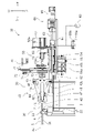
- FIG. 1 is a perspective view of the drain line straightening device 10 according to the embodiment.
- FIG. 2 is a left side view of the drain line straightening device 10.
- the drain wire straightening device 10 according to the present embodiment is a device that straightens the drain wire 2 of the multi-core cable 1.
- "correcting the drain wire 2" means to arrange the drain wire 2 composed of a plurality of metal strands in a straight line and then put them together so that the metal strands do not come apart.
- the drain wire straightening device 10 is configured to arrange the drain wire 2 in a straight line and then twist the drain wire 2 so that the metal strands do not disperse.
- the multi-core cable 1 is an electric wire in which a drain wire 2, a plurality of core wires 3, and a shield (not shown) are covered with a coating 4.
- the plurality of core lines 3 are used, for example, as signal lines for transmitting electrical signals.
- the shield (not shown) is a conductor that shields the core wire 3 from external noise.
- the shield covers the outside of the plurality of core wires 3.
- the drain wire 2 is electrically connected to the shield. During use, the drain wire 2 is grounded, which grounds the shield.
- the drain wire 2 is composed of a plurality of strands and is not covered with an insulator.
- the plurality of core wires 3 and the drain wire 2 are twisted inside the shield.
- the shield is further covered by an insulating coating 4.
- the multi-core cable 1 Before being attached to the drain wire straightening device 10, the multi-core cable 1 is subjected to a treatment of stripping the coating 4 at the end, a treatment of untwisting a plurality of twisted core wires 3 and a drain wire 2, and a treatment of untwisting.
- the process of separating the drain wire 2 and the core wire 3 is performed.
- the exposed portion of the drain wire 2 from the coating 4 is simply referred to as the drain wire 2
- each exposed portion of the plurality of core wires 3 from the coating 4 is simply referred to as the core wire 3. As shown in FIGS.
- the drain wire 2 and the core wire 3 are separated by bending the plurality of core wires 3 from the axial direction of the multi-core cable 1.
- the axial direction of the drain wire 2 coincides with the axial direction of the portion of the multi-core cable 1 covered with the coating 4 (hereinafter, also referred to as the covering portion 1a).
- the axial direction of the drain wire 2 does not have to coincide with the axial direction of the covering portion 1a.
- the drain line straightening device 10 includes a holding device 20, a gripping device 30, a moving device 60, a rotating device 70, and a control device 80.
- the holding device 20 is configured to hold the covered portion 1a of the multi-core cable 1.
- the holding device 20 includes a holding clamp 21 and an actuator 22.
- the holding clamp 21 includes a pair of holding claws 21L and 21R.
- the actuator 22 drives the holding claws 21L and 21R so as to approach or separate from each other.
- the multi-core cable 1 is held by being sandwiched between the holding claws 21L and 21R.
- the multi-core cable 1 is opened when the holding claws 21L and 21R are separated from each other.
- the tip end side of the multi-core cable 1 the side where the drain wire 2 is exposed in the axial direction of the multi-core cable 1 is referred to as the tip end side of the multi-core cable 1.
- the end of the drain wire 2 on the tip side of the multi-core cable 1 is referred to as the tip of the drain wire 2.
- the tip end side of the multi-core cable 1 held by the holding device 20 is the front of the drain wire straightening device 10, and the left and right sides seen from the front are the left and right of the drain wire straightening device 10, respectively.
- F, Rr, L, R, U, and D represent the front, back, left, right, top, and bottom of the drain line straightening device 10, respectively.
- these directions are for convenience of explanation, and do not limit the installation mode of the drain line straightening device 10 or the like.
- the gripping device 30 is a mechanism for gripping the drain wire 2 when the drain wire 2 is straightened.
- the gripping device 30 is arranged in front of the holding device 20.
- the gripping device 30 includes a gripping clamp 40 and a driving device 50.
- the gripping clamp 40 has a first clamp claw 41 and a second clamp claw 42 configured so that the drain wire 2 can be gripped.
- the drive device 50 drives the first clamp claw 41 and the second clamp claw 42 so as to grip or open the drain wire 2.
- the main part of the gripping clamp 40 including the first clamp claw 41 and the second clamp claw 42 is configured to rotate around a predetermined axis Ax by the rotating device 70.
- this axis Ax is also referred to as an axis Ax of the gripping clamp 40, or simply an axis Ax.
- the extension direction of the axis Ax of the gripping clamp 40 is also the moving direction of the gripping clamp 40 by the moving device 60.
- the axis Ax of the gripping clamp 40 coincides with the axis of the covering portion 1a of the multi-core cable 1 held by the holding device 20.
- the axis Ax substantially coincides with the axis of the drain line 2 before correction.
- the axis Ax of the gripping clamp 40 does not have to coincide with the axis of the covered portion 1a of the multi-core cable 1 and the drain wire 2 before straightening.
- the gripping clamp 40 includes a first clamp claw 41, a second clamp claw 42, a cam plate 43, a first link member 44, a second link member 45, and a first rotation shaft 46.
- a second rotating shaft 47 and a piston rod 48 are provided.
- the gripping clamp 40 is configured such that when the piston rod 48 is moved in the front-rear direction by the drive device 50, the first clamp claw 41 and the second clamp claw 42 approach or separate from each other.
- the front end of the piston rod 48 is connected to the drive device 50, and the rear end is connected to the cam plate 43.
- the piston rod 48 is moved in the front-rear direction by the drive device 50.
- the cam plate 43 moves in the front-rear direction.
- the cam plate 43 is configured in a plate shape.
- the cam plate 43 extends in the radial direction and the front-rear direction of the gripping clamp 40.
- the cam plate 43 includes a pair of elongated holes 43a and 43b.
- the first elongated hole 43a and the second elongated hole 43b are through holes that penetrate the cam plate 43 in the left-right direction.
- the first elongated hole 43a and the second elongated hole 43b are provided symmetrically with respect to the axis Ax.
- the first elongated hole 43a and the second elongated hole 43b each move away from the holding device 20 (here, toward the front of the drain line straightening device 10) in the extension direction of the axis Ax, and are radially outward from the grip clamp 40. It extends toward you.
- the first link member 44 and the second link member 45 are provided behind the cam plate 43 (between the cam plate 43 and the holding device 20).
- the first link member 44 and the second link member 45 are engaged with the first elongated hole 43a and the second elongated hole 43b, respectively.
- the front end portion of the first link member 44 is swingably engaged with the first elongated hole 43a.
- the central portion of the first link member 44 in the front-rear direction is rotatably supported by the first rotation shaft 46 extending in the left-right direction.
- the front end portion of the second link member 45 is swingably engaged with the second elongated hole 43b.
- the central portion of the second link member 45 in the front-rear direction is rotatably supported by the second rotation shaft 47 extending in the left-right direction.
- a first clamp claw 41 and a second clamp claw 42 are provided at the rear ends of the first link member 44 and the second link member 45, respectively.
- the first clamp claw 41 and the second clamp claw 42 face each other with the axis Ax of the gripping clamp 40 interposed therebetween.
- the first clamp claw 41 and the second clamp claw 42 are configured to mesh with each other when they come closer to each other by driving the drive device 50.
- FIG. 3 is a perspective view of the first clamp claw 41 and the second clamp claw 42. In FIG. 3, members other than the first clamp claw 41 and the second clamp claw 42 are not shown.
- the first clamp claw 41 includes a first meshing portion 41a that meshes with the second clamp claw 42.
- the first meshing portion 41a is provided with a plurality of substantially triangular comb teeth 41a1 arranged in the front-rear direction and a plurality of substantially triangular comb teeth 41a1 adjacent to each other in the left-right direction, and a plurality of substantially triangular comb teeth 41a2 arranged in the front-rear direction. And, including. In the anteroposterior view, the comb teeth 41a1 and the comb teeth 41a2 are arranged so that their hypotenuses face each other. The comb teeth 41a1 and the comb teeth 41a2 are staggered in the front-rear direction.
- the second clamp claw 42 includes a second meshing portion 42a that meshes with the first meshing portion 41a of the first clamp claw 41.
- the second meshing portion 42a is also provided with a plurality of substantially triangular comb teeth 42a1 arranged in the front-rear direction and a plurality of substantially triangular comb teeth 42a1 arranged adjacent to each other in the left-right direction, and a plurality of substantially triangular comb teeth 42a2 arranged in the front-rear direction. And, including. In the anteroposterior view, the comb teeth 42a1 and the comb teeth 42a2 are arranged so that their hypotenuses face each other.
- the comb teeth 42a1 and the comb teeth 42a2 are staggered in the front-rear direction. Further, the comb teeth 42a1 of the second clamp claw 42 are arranged alternately with the comb teeth 41a1 facing each other of the first clamp claw 41. The comb teeth 42a2 of the second clamp claw 42 are arranged alternately with the comb teeth 41a2 facing each other of the first clamp claw 41. Therefore, when the first clamp claw 41 and the second clamp claw 42 come closer to each other by driving the drive device 50, they mesh with each other.
- the first clamp claw 41 has a first grip portion 41b cut out in a shape corresponding to the cross-sectional shape of the drain wire 2.
- the first grip portion 41b is a substantially semicircular notch corresponding to the radius of the drain line 2 in the front-back direction view.
- the first grip portion 41b is formed at a position where the hypotenuse of the comb teeth 41a1 and the hypotenuse of the comb teeth 41a2 intersect in the front-back direction view.
- the first grip portion 41b is provided so as to penetrate the first mesh portion 41a in the front-rear direction.
- the second clamp claw 42 has a second grip portion 42b that is cut out in a shape corresponding to the cross-sectional shape of the drain wire 2 and is arranged so as to face the first grip portion 41b.
- the second grip portion 42b is also cut out in a substantially semicircular shape corresponding to the radius of the drain line 2 in the front-rear direction view.
- the second grip portion 42b is formed at a position where the hypotenuse of the comb teeth 42a1 and the hypotenuse of the comb teeth 42a2 intersect in the front-back direction view.
- the second grip portion 42b is provided so as to penetrate the second meshing portion 42a in the front-rear direction.
- the first grip portion 41b and the second grip portion 42b form a substantially cylindrical grip portion corresponding to the diameter of the drain wire 2.
- the axis of the grip formed when the first grip 41b and the second grip 42b are engaged with each other coincides with the rotation center of the grip clamp 40, that is, the axis Ax of the grip clamp 40. Therefore, when the first clamp claw 41 and the second clamp claw 42 mesh with each other, the drain wire 2 is gripped on the axis Ax of the grip clamp 40.
- the drive device 50 is provided in front of the grip clamp 40.
- the drive device 50 is connected to the front end portion of the piston rod 48 of the gripping clamp 40, and is configured to move the piston rod 48 in the front-rear direction.
- the drive device 50 includes a first cylinder 51, a second cylinder 52, a support base 53 of the first cylinder 51, a linear guide 54, and an electromagnetic valve provided in an air supply path (not shown). It is provided with 55a and 55b and pressure reducing valves 56a and 56b also provided in the air supply path.
- the first cylinder 51 is the first actuator of the drive device 50.
- the first cylinder 51 is an air cylinder provided with a cylinder rod 51a that expands and contracts in the front-rear direction. Compressed air is supplied to the first cylinder 51 from an air supply path (not shown) for the first cylinder 51.
- the cylinder rod 51a of the first cylinder 51 expands and contracts due to the compressed air supplied or discharged.
- the supply or discharge of compressed air to the first cylinder 51 is controlled by an electromagnetic valve 55a provided in the air supply path.
- the rear end portion (tip portion) of the cylinder rod 51a is connected to the front end portion of the piston rod 48.
- the first cylinder 51 is supported by a support base 53.
- the support 53 is slidably engaged with the linear guide 54.
- the linear guide 54 extends in the front-rear direction.
- the first cylinder 51 is configured to be movable in the front-rear direction along the linear guide 54.
- the second cylinder 52 is arranged in front of the support base 53.
- the second cylinder 52 is the second actuator of the drive device 50.
- the second cylinder 52 is also an air cylinder here.
- the second cylinder 52 is an air cylinder having a larger diameter than the first cylinder 51.
- the second cylinder 52 includes a cylinder rod 52a that expands and contracts in the front-rear direction. Compressed air is supplied to the second cylinder 52 from an air supply path (not shown) for the second cylinder 52.
- the cylinder rod 52a of the second cylinder 52 expands and contracts due to the compressed air supplied or discharged.
- the supply or discharge of compressed air to the second cylinder 52 is controlled by an electromagnetic valve 55b provided in the air supply path.
- the rear end portion (tip portion) of the cylinder rod 52a is connected to the support base 53.
- the axial force when the first cylinder 51 extends the cylinder rod 51a is adjusted to a predetermined force by the pressure reducing valve 56a provided in the air supply path.
- the pressure reducing valve 56a is configured so that the pressure of the compressed air supplied to the first cylinder 51 can be adjusted.
- the axial force when the second cylinder 52 extends the cylinder rod 52a is adjusted to a predetermined force by the pressure reducing valve 56b provided in the air supply path.
- the axial force when the second cylinder 52 extends the cylinder rod 52a is set to be larger than the axial force when the first cylinder 51 extends the cylinder rod 51a.
- the moving device 60 supports the gripping device 30 and is configured to be able to move the gripping device 30 in the front-rear direction along the axis Ax of the gripping clamp 40.
- the first clamp claw 41 and the second clamp claw 42 as gripping members for gripping the drain wire 2 are moved in the front-rear direction by the moving device 60.
- the moving device 60 includes a moving table 61, a linear guide 62, a ball screw 63, a nut 64, and a first motor 65.
- the gripping device 30 is mounted on the moving table 61.
- the moving table 61 supports the gripping device 30.
- the moving table 61 is slidably engaged with the linear guide 62.
- the linear guide 62 extends in the front-rear direction.
- the moving table 61 is configured to be movable in the front-rear direction along the linear guide 62. As the moving table 61 moves in the front-rear direction, the gripping device 30 moves in the front-rear direction.
- a nut 64 is connected to the moving table 61.
- a ball screw 63 is engaged with the nut 64.
- the ball screw 63 is arranged so that the axis of the ball screw 63 faces in the front-rear direction.
- the front end of the ball screw 63 is connected to the first motor 65.
- the ball screw 63 rotates about the axis.
- the moving table 61 moves along the linear guide 62 via the nut 64 that meshes with the ball screw 63.
- the moving device 60 can change the speed at which the gripping device 30 is moved in the front-rear direction by changing the rotation speed of the first motor 65.
- the rotating device 70 is a mechanism for rotating the gripping clamp 40 around the axis Ax.
- the first clamp claw 41 and the second clamp claw 42 as gripping members for gripping the drain wire 2 are rotated around the axis Ax by the rotating device 70.
- the rotating device 70 is mounted on the moving table 61 of the moving device 60 together with the gripping device 30.
- the rotating device 70 moves in the front-rear direction together with the gripping device 30.
- the rotating device 70 includes a second motor 71, a motor-side pulley 72, a clamp-side pulley 73, and a timing belt 74.
- the second motor 71 is provided above the gripping clamp 40.
- the spindle of the second motor 71 extends in the front-rear direction.
- the spindle of the second motor 71 rotates around an axis parallel to the axis Ax of the gripping clamp 40.
- a motor-side pulley 72 is connected to the main shaft of the second motor 71.
- the clamp side pulley 73 is connected to the gripping clamp 40.
- the timing belt 74 is an endless belt, and is wound around a motor-side pulley 72 and a clamp-side pulley 73.
- the rotational force of the second motor 71 is transmitted to the grip clamp 40 via the motor side pulley 72, the timing belt 74, and the clamp side pulley 73.
- the rotation device 70 may be configured so that the speed at which the gripping device 30 is rotated can be changed by changing the rotation speed of the second motor 71.
- the drain line straightening device 10 includes a control device 80.
- the control device 80 controls the holding device 20, the driving device 50 of the gripping device 30, the moving device 60, and the rotating device 70.
- the control device 80 is connected to the actuator 22, the solenoid valve 55a for the first cylinder 51, the solenoid valve 55b for the second cylinder 52, the first motor 65, and the second motor 71, and controls their operations. ..
- the configuration of the control device 80 is not particularly limited.
- the control device 80 may include, for example, a central arithmetic processing unit (hereinafter referred to as a CPU), a ROM in which a program executed by the CPU or the like is stored, a RAM, or the like.
- a CPU central arithmetic processing unit
- ROM read-only memory
- RAM random access memory
- Each part of the control device 80 may be configured by software or hardware. Further, each part may be a processor or a circuit.
- the control device 80 may be, for example, a programmable controller or a computer. The operation control of each part by the control device 80 will be described in the following description of the straightening process of the drain line 2.
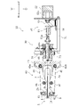
- FIG. 4 is a cross-sectional view of a main part of the drain line straightening device 10 immediately before starting straightening of the drain line 2. In FIG. 4, some members are not shown. The same applies to FIGS. 5 to 9.
- the drain line straightening device 10 drives the moving device 60 (see FIG. 1) to move the gripping device 30 backward. As a result, almost the entire drain line 2 moves to the front of the first clamp claw 41 and the second clamp claw 42.
- almost the entire drain line 2 is contained in the space between the first link member 44 and the second link member 45.
- the gripping device 30 that actually moves, but in the following, the change in the positional relationship between the members is appropriately expressed as the movement of the member that does not actually move.
- the first clamp claw 41 and the second clamp claw 42 are separated from each other.
- the state in which the first clamp claw 41 and the second clamp claw 42 are separated is also referred to as an open grip clamp 40 in the following.
- FIG. 5 is a cross-sectional view of a main part of the drain line straightening device 10 at the start of straightening of the drain line 2.
- the cylinder rod 51a of the first cylinder 51 is extended.
- the cylinder rod 51a pushes the piston rod 48 rearward.
- the piston rod 48 is moving backward from the state shown in FIG.
- the cam plate 43 connected to the piston rod 48 also moves backward.
- the rear end portions of the first link member 44 and the second link member 45 have the first elongated hole 43a and the second elongated hole, respectively.
- the grip clamp 40 moves outward in the radial direction.
- the first link member 44 and the second link member 45 rotate around the first rotation shaft 46 and the second rotation shaft 47, respectively.
- the first clamp claw 41 and the second clamp claw 42 provided at the rear ends of the first link member 44 and the second link member 45 move inward in the radial direction of the gripping clamp 40, respectively.
- the first clamp claw 41 and the second clamp claw 42 grip the drain wire 2.
- the drain wire 2 is gripped by the first grip portion 41b (see FIG. 3) of the first clamp claw 41 and the second grip portion 42b (see FIG. 3) of the second clamp claw 42. .. Even if the drain wire 2 is not located between the first grip portion 41b and the second grip portion 42b while the first clamp claw 41 and the second clamp claw 42 are approaching, the drain wire 2 is a comb tooth 41a1. , 41a2, 42a1 or 42a2 is guided between the first grip portion 41b and the second grip portion 42b by the hypotenuse. As shown in FIG. 5, at this time, the first clamp claw 41 and the second clamp claw 42 grip the root portion 2a of the drain wire 2.
- the root portion 2a of the drain line 2 is, for example, a portion closer to the covering portion 1a than one third of the exposed length in the axial direction of the drain line 2, and more preferably, the axial direction of the drain line 2. It means a portion closer to the covering portion 1a than one-fifth of the exposure length with respect to.
- the gripping force of the gripping clamp 40 is generated from the driving force of the first cylinder 51.
- the gripping of the drain wire 2 by the driving force of the first cylinder 51 is also referred to as “weak gripping”
- the gripping operation of the drain wire 2 is also referred to as “weak gripping”.
- the degree of gripping force in the case of weak gripping will be described later.
- the first grip portion 41b and the second grip portion 42b are in contact with the drain line 2 with respect to the approaching and separating directions of the first clamp claw 41 and the second clamp claw 42. Since the first meshing portion 41a and the second meshing portion 42a mesh with each other, the first clamp claw 41 and the second clamp claw 42 have a drain wire 2 with respect to the approaching and separating directions of the first clamp claw 41 and the second clamp claw 42. It comes into contact with and stops. Further, the first grip portion 41b and the second grip portion 42b are cut out in a shape corresponding to the cross-sectional shape of the drain wire 2. Therefore, the first clamp claw 41 and the second clamp claw 42 are in contact with or at least close to the drain line 2 in directions other than the approaching and separating directions.
- the moving device 60 is driven with the first clamp claw 41 and the second clamp claw 42 in contact with the drain line 2, and the first clamp claw 41 and the second clamp claw 42 are brought into contact with the drain line 2. Move toward the tip side (here, forward).
- ironing control the control of the previous step in which the first clamp claw 41 and the second clamp claw 42 are brought into contact with the drain wire 2 and the control of this step are collectively referred to as "ironing control”.
- the control device 80 controls the drive device 50 and the mobile device 60 to execute ironing control.
- the first grip portion 41b of the first clamp claw 41 and the second grip portion 42b of the second clamp claw 42 remain in contact with the outer peripheral portion of the drain wire 2 (specifically, the drain wire 2 is weakly gripped).
- (Still) move along the axis Ax of the gripping clamp 40.
- the drain wire 2 is squeezed toward the tip side, and a plurality of strands constituting the drain wire 2 are put together.
- the drain wire 2 is formed into a straight line.
- the first clamp claw 41 and the second clamp claw 42 weakly grip the drain wire 2. Therefore, when the gripping clamp 40 is moved along the drain line 2, it easily slides between the first clamp claw 41 and the second clamp claw 42 and the drain line 2.
- the gripping force of the gripping clamp 40 at the time of weak grip is set to a gripping force so that the first clamp claw 41 and the second clamp claw 42 easily slide between the drain wire 2 and the drain wire 2 is not pulled too much. ing.
- FIG. 6 is a cross-sectional view of a main part of the drain line straightening device 10 at the end of ironing control.
- the gripping device 30 is moved until the first clamp claw 41 and the second clamp claw 42 reach the tip portion 2b of the drain wire 2.
- the tip portion 2b of the drain line 2 is, for example, a portion closer to the tip than one third of the exposure length in the axial direction of the drain line 2, and more preferably, the exposure in the axial direction of the drain line 2. It means the part closer to the tip than one fifth of the length.
- the gripping force is strengthened as compared with the case of ironing control, and the drain wire 2 is gripped by the first clamp claw 41 and the second clamp claw 42.
- the rotating device 70 is driven to rotate the first clamp claw 41 and the second clamp claw 42 that grip the drain wire 2 around the axis Ax of the gripping clamp 40.
- the control of strongly gripping the drain wire 2 by the first clamp claw 41 and the second clamp claw 42 and the control of rotating the first clamp claw 41 and the second clamp claw 42 are collectively referred to as "rotation control”. ..
- the control device 80 is configured to execute rotation control after ironing control.
- the control device 80 executes rotation control in a state where the first clamp claw 41 and the second clamp claw 42 are located at the tip end portion 2b of the drain wire 2.
- FIG. 7 is a cross-sectional view of a main part of the drain line straightening device 10 during rotation control.
- the cylinder rod 52a of the second cylinder 52 is extended.
- the support base 53 moves backward from the state shown in FIGS. 4 to 6, in other words, the weakly gripped state.
- the second cylinder 52 presses the first cylinder 51 rearward via the support base 53.
- the second cylinder 52 pushes the piston rod 48 rearward via the first cylinder 51.
- the gripping force of the gripping clamp 40 at this time is generated from the driving force of the second cylinder 52.
- the axial force of the second cylinder 52 is set to be larger than the axial force of the first cylinder 51. Therefore, in the state of FIG. 7, the gripping force with which the first clamp claw 41 and the second clamp claw 42 grip the drain line 2 is larger than the state shown in FIGS. 4 to 6 (weak gripping state).
- the gripping of the drain wire 2 by the driving force of the second cylinder 52 is also referred to as “strong gripping”, and the gripping operation of the drain wire 2 is also referred to as “strong gripping”.
- the first cylinder 51 may or may not be driven.
- the first clamp claw 41 and the second clamp claw 42 that grip the drain wire 2 are further rotated around the axis Ax of the grip clamp 40.
- the second motor 71 (see FIG. 2) of the rotating device 70 is driven.
- the drain wire 2 is twisted by the rotation of the first clamp claw 41 and the second clamp claw 42 that strongly grip the drain wire 2 around the axis Ax.
- the gripping force of the gripping device 30 in strong gripping is set so that the gripping force does not slip between the first clamp claw 41 and the second clamp claw 42 and the drain line 2 when the gripping clamp 40 is rotated. There is.
- the drain wire 2 can be twisted as many times as the number of times set in the control device 80.
- the shape of the drain wire 2 formed linearly in the ironing control can be stably maintained.
- the rotation control it is possible to correct the portion of the drain wire 2 on the covering portion 1a side with respect to the portion gripped by the first clamp claw 41 and the second clamp claw 42.
- the control device 80 may drive the moving device 60 so that the first clamp claw 41 and the second clamp claw 42 pull the drain wire 2 toward the tip end side.
- the driving force of the moving device 60 at this time is preferably such that the gripping clamp 40 does not move forward.
- the gripping clamp 40 may move with respect to the drain line 2 by the driving force of the moving device 60 in the rotation control.
- the moving device 60 is not driven in the rotation control, and the first clamp claw 41 and the second clamp claw 42 do not positively pull the drain wire 2 toward the tip side, but the drain wire 2 is twisted to cause the drain wire. As 2 tends to shrink, as a result, tension is applied to the drain wire 2 to pull it toward the tip end side.
- the gripping force of the first clamp claw 41 and the second clamp claw 42 is switched to a gripping force weaker than the gripping force in the rotation control.
- the gripping of the first clamp claw 41 and the second clamp claw 42 is switched to the same weak grip as in the case of ironing control.
- the gripping force of the gripping clamp 40 at this time may be a third gripping force set to be weaker than that at the time of rotation control.
- the drain line straightening device 10 may be configured so that the gripping force of the gripping clamp 40 can be set to the third gripping force.
- the first clamp claw 41 and the second clamp claw 42 are rotated around the axis Ax of the gripping clamp 40 and moved toward the tip end side of the drain line 2 along the axis Ax.
- the first clamp claw 41 and the second clamp claw 42 are separated from the drain wire 2.
- the control device 80 is configured to execute the withdrawal control after the rotation control.
- FIG. 8 is a cross-sectional view of a main part of the drain line straightening device 10 at the start of withdrawal control.
- FIG. 9 is a cross-sectional view of a main part of the drain line straightening device 10 at the end of withdrawal control.
- the gripping clamp 40 in the detachment control, the gripping clamp 40 is driven by the first cylinder 51 and the second cylinder 52 is not used, as in the ironing control. As a result, the gripping clamp 40 weakly grips the drain wire 2. Further, in the detachment control, the gripping clamp 40 is rotated around the axis Ax. Further, in the detachment control, the gripping clamp 40 is moved toward the tip end side of the drain line 2.
- the first clamp claw 41 and the second clamp claw 42 twist the drain wire 2 while slightly sliding with respect to the drain wire 2, and move the position where the drain wire 2 is gripped to the tip end side of the drain wire 2.
- the gripping position of the drain line 2 by the first clamp claw 41 and the second clamp claw 42 is the starting point of the correction of the drain line 2, but the gripping position and the drain line 2 on the tip side of the gripping position are not corrected. Therefore, in the detachment control, the gripping position of the drain wire 2 is moved to the tip side while twisting the drain wire 2. As a result, the uncorrected portion of the drain line 2 is gradually reduced. As shown in FIG. 9, when the first clamp claw 41 and the second clamp claw 42 are separated from the drain line 2, the entire drain line 2 is corrected.
- the grip of the drain wire 2 is weakly gripped so that the drain wire 2 is not pulled too much by the movement of the grip clamp 40. Further, in the detachment control, it is preferable to associate the rotation speed and the movement speed of the gripping clamp 40 with each other in order to control the number of times the drain wire 2 is twisted. Therefore, in the detachment control, the gripping clamp 40 is moved at a lower speed than in the ironing control. In the ironing control, it is not necessary to associate the rotational speed of the gripping clamp 40 with the moving speed, so that the gripping clamp 40 is moved at a higher speed than in the detachment control.
- the first clamp claw 41 and the second clamp claw 42 in a state where the first clamp claw 41 and the second clamp claw 42 as gripping members are in contact with the drain wire 2.
- the ironing control is performed to move the drain line 2 toward the tip end side. After the ironing control, the gripping force is stronger than that in the ironing control so that the first clamp claw 41 and the second clamp claw 42 grip the drain wire 2, and the first clamp claw 41 and the second clamp claw 42 are gripped.
- Rotation control is performed to rotate the clamp 40 around the axis Ax (in other words, around the axis of the drain line 2 after ironing control).
- the strands of the drain wire 2 can be put together and the drain wire 2 can be formed into a straight line. Further, in the rotation control performed after the ironing control, the gripping clamp 40 is rotated in a state where the drain wire 2 is gripped more strongly than in the ironing control. Therefore, the drain wire 2 can be twisted firmly by the rotation control.
- the first clamp claw 41 and the second clamp claw 42 grip the drain wire 2 weaker than in the rotation control. Therefore, even if the first clamp claw 41 and the second clamp claw 42 are moved toward the tip end side of the drain wire 2 in the ironing control, the drain wire 2 is not pulled very strongly. Therefore, it is difficult to cut the strand of the drain wire 2.
- the drain wire is not straightened, for example, if you try to insert the drain wire into a heat shrink tube, some problems will occur.
- the uncorrected drain wire has a twisting habit when it is twisted in the coating, and it is difficult to insert it into the heat-shrinkable tube unless it is straightened.
- the uncorrected drain wires are loose, and if they are not put together, it is still difficult to insert them into the heat-shrinkable tube.
- an axial force is applied during insertion into the heat shrink tubing, the uncorrected drain wire will easily buckle. Therefore, it is preferable that the drain wire is formed into a straight line and is twisted (corrected) firmly.
- the root portion of the drain wire is first gripped by the gripping member, and then the gripping member is moved toward the tip end side of the drain wire.
- the strands that were not separated from the other strands tend to be wound around the outer periphery of the stranded wire in which the other strands are twisted.
- the wire wound around the outer peripheral portion of the stranded wire tends to cause a defect in the post-process.
- the strands wound around the outer peripheral portion cause irregularities on the outer peripheral portion of the drain wire, so that the insertion resistance when inserting the heat-shrinkable tube into the drain wire tends to increase.
- the wire wound around the outer peripheral portion is shorter than the other wires, it tends to be defective when the crimp terminal is crimped to the drain wire. Further, if the drain wire is twisted while moving the grip portion, the drain wire is not twisted firmly because the drain wire and the grip member slip between each other. Therefore, the drain wire tends to buckle easily. Therefore, according to the knowledge of the inventor of the present application, it is preferable to twist the drain wire after squeezing the drain wire to gather the strands.
- the drain wire is not twisted only by squeezing it, the strands at the tip of the drain wire are not particularly organized and tend to remain loose. Further, when the drain wire is only twisted and squeezed, the twisting habit of the drain wire tends to remain uncorrected.
- the drain line straightening device 10 according to the present embodiment is set to execute rotation control after executing ironing control. Therefore, it is possible to suppress the above-mentioned problems. Further, the drain wire straightening device 10 according to the present embodiment executes rotation control in a state where the first clamp claw 41 and the second clamp claw 42 are positioned at the tip end portion 2b of the drain wire 2. Therefore, it is possible to twist the drain wire 2 in a state where most of the drain wire 2 is squeezed. Therefore, the drain wire 2 can be corrected better.
- the gripping force that the gripping clamp 40 grips the drain wire 2 during ironing control is the gripping force that the gripping clamp 40 grips the drain wire 2 during rotation control. Is set weaker than. Therefore, it is possible to suppress a problem that the strand of the drain wire 2 is cut or the drain wire 2 is scratched. Further, in the rotation control, since the drain wire 2 is gripped more strongly than in the ironing control, the drain wire 2 can be twisted firmly by the rotation control.
- the control device 80 causes the first clamp claw 41 and the second clamp claw 42 to grip the drain wire 2 with a weaker gripping force than in the rotation control in the ironing control.
- the control device 80 does not put the first clamp claw 41 and the second clamp claw 42 in a state where they are only in contact with the drain wire 2 and are not gripped.
- the drain wire 2 is pulled toward the tip side by the first clamp claw 41 and the second clamp claw 42. Therefore, it is possible to better shape the drain wire 2 into a straight line.
- the control device 80 starts the ironing control in a state where the first clamp claw 41 and the second clamp claw 42 are located at the root portion 2a of the drain wire 2.
- the drain wire 2 can be well organized. Further, according to such control, most of the drain wire 2 from the root portion 2a to the tip portion 2b can be squeezed.
- the control device 80 attaches to the first clamp claw 41 and the second clamp claw 42 with a weaker gripping force than in the rotation control in the detachment control after the rotation control.
- the drain wire 2 is gripped, and the first clamp claw 41 and the second clamp claw 42 are rotated around the axis Ax of the gripping clamp 40. Further, the control device 80 moves the first clamp claw 41 and the second clamp claw 42 toward the tip end side of the drain line 2, and separates the first clamp claw 41 and the second clamp claw 42 from the drain line 2.
- the detachment control by moving the first clamp claw 41 and the second clamp claw 42 while rotating, the portion of the drain wire 2 that was not twisted in the rotation control, that is, the first clamp claw 41 and the second clamp claw 41. 2
- the gripped portion by the clamp claw 42 and the portion on the tip side of the gripped portion can also be twisted.
- the detachment control is performed until the first clamp claw 41 and the second clamp claw 42 are removed from the drain wire 2, the drain wire 2 can be twisted to the tip by the detachment control.
- the gripping force of the gripping clamp 40 during the detachment control is weaker than that during the rotation control. Therefore, the problem that the strand of the drain wire 2 is cut can be suppressed.
- the moving speeds of the first clamp claw 41 and the second clamp claw 42 with respect to the drain line 2 in the ironing control are the first clamp claw 41 and the first clamp claw 41 with respect to the drain line 2 in the detachment control. It is faster than the moving speed of the second clamp claw 42. According to such control, the time required for straightening the drain line 2 can be reduced.
- the first clamp claw 41 has a first grip portion 41b cut out in a shape corresponding to the cross-sectional shape of the drain wire 2, and the second clamp claw 42.
- the drain wire 2 is gripped by the first grip portion 41b and the second grip portion 42b notched in a shape corresponding to the cross-sectional shape of the drain wire 2. Therefore, the drain wire 2 is easily organized in the ironing control, and the drain wire 2 is easily gripped in the rotation control.
- the control device 80 may drive the moving device 60 so that the first clamp claw 41 and the second clamp claw 42 pull the drain wire 2 toward the tip side in the rotation control. In that case, since the drain wire 2 is twisted while being pulled toward the tip side during rotation control, the drain wire 2 can be better formed into a straight line. Further, it has been confirmed by the inventor of the present application that the binding of the twisted drain wire 2 can be further strengthened by such control.
- the detachment control is performed to separate the grip clamp 40 from the drain line 2 while rotating it, but the detachment control may not be performed.
- the inventor of the present application has confirmed that even if the gripping clamp 40 is opened immediately after the rotation control, only a problem that the convergence of the portion gripped by the gripping clamp 40 of the drain line 2 is slightly weak occurs.
- the gripping clamp 40 may be rotated without moving while the drain wire 2 is weakly gripped. Even in this case, since the drain wire 2 slips between the first clamp claw 41 and the second clamp claw 42, it is not twisted because it is gripped by the first clamp claw 41 and the second clamp claw 42 in the rotation control. The part can be twisted.
- the gripping clamp 40 did not rotate in the ironing control, but it may rotate. Further, in the above-described embodiment, the grip clamp 40 weakly grips the drain wire 2 in the ironing control, but the drain wire 2 may not be gripped and may only be in contact with the drain wire 2.
- the configuration of the drain line straightening device is not limited to the above.
- the drain wire straightening device may rotate the multi-core cable held by the holding device around a predetermined axis instead of the gripping device.
- the drain wire straightening device may rotate both the gripping device and the multi-core cable around a predetermined axis, thereby rotating the drain wire with respect to the covering portion of the multi-core cable.
- the drain wire straightening device may move the multi-core cable held by the holding device in the axial direction of the gripping device instead of the gripping device.
- the drain wire straightening device may be configured to move both the gripping device and the multi-core cable in the axial direction of the gripping device, thereby squeezing the drain wire toward the tip side.
- the gripping force of the gripping device may be switched by switching the pressure of the air supplied to one air cylinder.
- the actuator of the gripping device does not have to be an air-driven actuator.
- the configuration of the gripping device is not particularly limited as long as the gripping force can be switched between strong and weak.
- the configuration of the holding device, the moving device, and the rotating device is also not limited.
- the drain line straightening device may be divided into a device for performing ironing control and a device for performing rotation control and detachment control.
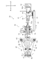
- FIG. 10 is a perspective view of the drain wire straightening device 10 separated into the ironing device 10X and the twisting device 10Y. As shown in FIG. 10, in this embodiment, the ironing device 10X and the twisting device 10Y are provided side by side.
- the holding device 20 for holding the multi-core cable 1 is configured to move or swivel and deliver the multi-core cable 1 processed by the ironing device 10X to the twisting device 10Y (movement). The latter multi-core cable 1 is indicated by a chain double-dashed line).
- the operation of the holding device 20, the ironing device 10X, and the twisting device 10Y is controlled by the control device 80 (see FIG. 1).
- the control device 80 may be distributed and arranged in the holding device 20, the ironing device 10X, and the twisting device 10Y, or may be integrated in one place.
- the ironing device 10X includes a first gripping clamp 40X, a first driving device 50X, and a first moving device 60X.
- the configurations of the first gripping clamp 40X, the first driving device 50X, and the first moving device 60X may be the same as the configurations of the gripping clamp 40, the driving device 50, and the moving device 60 of the first-described embodiment, respectively.
- the first drive device 50X drives the clamp claws 41X and 42X of the first gripping clamp 40X so as to grip or open the drain wire 2.
- the first drive device 50X is configured so that at least the first gripping clamp 40X can weakly grip the drain wire 2.
- the gripping force of the first gripping clamp 40X generated by the first driving device 50X may not be changed from the gripping force of weak gripping.
- the first moving device 60X is configured to move the first gripping clamp 40X along the axis Ax.
- the first moving device 60X thereby moves the first gripping clamp 40X so as to separate from the covering portion 1a of the multi-core cable 1.
- the operation of the ironing control by the ironing device 10X may be the same as that of the first embodiment.
- ironing may be performed up to the tip of the drain wire 2.
- the ironing device 10X is not provided with a rotating device, but may be provided with a rotating device and can perform ironing control while rotating the first gripping clamp 40X.
- the ironing device 10X does not need to firmly grip the drain wire 2. Therefore, the squeezing device 10X is provided with a squeezing member (for example, a claw for squeezing) that contacts the drain wire 2 so as to surround the drain wire 2 instead of the first gripping clamp 40X that grips the drain wire 2. May be good.
- the ironing member may be steadily configured in a direction approaching or separating from the drain line 2.
- the ironing device 10X may have a gripping member which is provided so as to surround the drain wire 2 and is in contact with or separated from the drain wire 2 by the drive of the drive device as in this embodiment.
- the twisting device 10Y includes a second gripping clamp 40Y, a second driving device 50Y, a second moving device 60Y, and a rotating device 70.
- the configuration of the twisting device 10Y may be the same as the configuration of the drain wire straightening device 10 described first.
- the second driving device 50Y drives the clamp claws 41Y and 42Y of the second gripping clamp 40Y so as to grip or open the drain wire 2.
- the second drive device 50Y is configured so that at least the second gripping clamp 40Y can strongly grip the drain wire 2.
- the gripping force of the second gripping clamp 40Y generated by the second driving device 50Y may not be changed from the gripping force of strong gripping.
- the second moving device 60Y is configured to move the second gripping clamp 40Y along the axis Ax2.
- the axis Ax2 is the rotation axis of the second gripping clamp 40Y, and its extension direction coincides with the axis direction of the drain line 2 after squeezing attached to the twisting device 10Y.
- the rotating device 70 rotates the second gripping clamp 40Y around the axis Ax2.
- the operation of rotation control by the twisting device 10Y may be the same as that of the first embodiment.
- the twisting device 10Y may or may not be set to perform detachment control. When the detachment control is not performed, the twisting device 10Y may not include the second moving device 60Y.
- the drain wire straightening device 10 uses a plurality of clamps that grip the drain wire 2 with different gripping forces instead of the clamps that can switch the gripping force for gripping the drain wire 2.
- the drain wire straightening device 10 also corrects the drain wire 2 satisfactorily by suppressing cutting or insufficient twisting of the strands of the drain wire 2 for the same reason as in the first embodiment. can do.
- the holding device for holding the drain wire may be provided with, for example, an articulated robot arm.
- an articulated robot arm When an articulated robot arm is used as a holding device for a drain wire straightening device separated into the above-mentioned ironing device and twisting device, the robot arm is, for example, a multi-core cable from another device to the ironing device. Transport, transport of the multi-core cable from the ironing device to the twisting device, transport of the multi-core cable from the twisting device to another device, and the like may be performed.
- the robot arm may, for example, transport a multi-core cable from another device to the drain wire straightening device.
- the multi-core cable may be transported from the drain wire straightening device to another device. Regardless of the application to any of the above drain wire straightening devices, the relative movement of the gripping clamp and the multi-core cable in ironing control, the rotation of the multi-core cable in rotation control, and the gripping clamp and multi-core cable in detachment control. The relative movement with and the rotation of the multi-core cable may be performed by the movement of the robot arm.
- the drain wire straightening may be performed without using the drain wire straightening device.
- the straightening of the drain wire may be performed by using a gripping tool capable of gripping the drain wire and changing the gripping force.
- the operator may hold the gripping tool in his hand and perform the straightening work of the drain wire.
- the portion of the gripper that grips the drain wire may be rotated.
- the device, tool, instrument, etc. for realizing the drain wire straightening method disclosed here are not particularly limited.
Landscapes
- Wire Processing (AREA)
Abstract
Description
以下、図面を参照しながら、本発明の実施の形態について説明する。図1は、一実施形態に係るドレイン線矯正装置10の斜視図である。図2は、ドレイン線矯正装置10の左側面図である。本実施形態に係るドレイン線矯正装置10は、多芯ケーブル1のドレイン線2を矯正する装置である。ここで、「ドレイン線2を矯正する」とは、複数の金属素線からなるドレイン線2を直線状に整えた上で、金属素線がばらけないようにまとめることを言う。ここでは、ドレイン線矯正装置10は、ドレイン線2を直線状に整えた上で、金属素線がばらけないようにドレイン線2を撚るように構成されている。多芯ケーブル1は、ドレイン線2と複数のコア線3とシールド(図示省略)とが被覆4によって覆われた電線である。複数のコア線3は、例えば、電気信号を伝達する信号線として使用される。図示しないシールドは、コア線3を外部のノイズから遮蔽する導体である。シールドは、複数のコア線3の外側を覆っている。ドレイン線2は、シールドに電気的に接続されている。使用時にはドレイン線2は接地され、これによりシールドが接地される。前述したように、ドレイン線2は、複数の素線からなり、絶縁体による被覆はされていない。複数のコア線3とドレイン線2とはシールドの内部において撚り合わされている。シールドは、さらに絶縁体の被覆4によって覆われている。
以下では、ドレイン線2を矯正するプロセスについて説明する。図4は、ドレイン線2の矯正を開始する直前のドレイン線矯正装置10の要部の断面図である。図4では、一部の部材の図示を省略している。図5~図9についても同様である。図4に示すように、ドレイン線2の矯正を開始する前には、ドレイン線矯正装置10は、移動装置60(図1参照)を駆動して把持装置30を後方に移動させる。これにより、ドレイン線2のほぼ全体が、第1クランプ爪41および第2クランプ爪42よりも前方まで移動する。ドレイン線2の矯正を開始する直前において、ドレイン線2のほぼ全体は、第1リンク部材44と第2リンク部材45との間の空間に収まっている。なお、上記では実際に移動するのは把持装置30であるが、部材間の位置関係の変更は、以下では適宜、実際には移動しない方の部材の移動としても表現する。図4に示すように、このとき、第1クランプ爪41と第2クランプ爪42とは離れている。第1クランプ爪41と第2クランプ爪42とが離れた状態を、以下では、把持クランプ40が開いているとも言う。
以下では、上記したドレイン線2の矯正プロセスに至るまでの過程で本願発明者が得た知見も交えながら、本実施形態に係るドレイン線矯正装置10の作用効果について説明する。
以上、本発明の一実施形態について説明した。ただし、上記実施形態は例示に過ぎず、他にも種々の実施形態が可能である。例えば、上記した実施形態では、把持クランプ40を回転させながらドレイン線2から離脱させる離脱制御が行われたが、離脱制御は行われなくてもよい。本願発明者は、回転制御後にすぐ把持クランプ40を開いても、ドレイン線2の把持クランプ40によって把持された部分の収束がやや弱い程度の問題しか発生しないことを確認している。また、離脱制御の代わりに、ドレイン線2を弱把持した状態で、把持クランプ40を移動させずに回転させてもよい。この場合でも、ドレイン線2と第1クランプ爪41および第2クランプ爪42との間が滑るため、回転制御において第1クランプ爪41および第2クランプ爪42に把持されていたために撚れなかった部分を撚ることができる。
2 ドレイン線
2a 根元部
2b 先端部
3 コア線
4 被覆
10 ドレイン線矯正装置
20 保持装置
30 把持装置
40 把持クランプ
41 第1クランプ爪(第1クランプ)
41b 第1把持部
42 第2クランプ爪(第2クランプ)
42b 第2把持部
50 駆動装置
60 移動装置
70 回転装置
80 制御装置
Claims (15)
- 被覆に覆われた被覆部分と、前記被覆部分から露出したドレイン線と、を有する多芯ケーブルの前記被覆部分を保持する保持装置と、
予め定められた軸線上で前記ドレイン線を把持することが可能に構成された把持部材と、
前記ドレイン線を把持させまたは開放させるように前記把持部材を駆動する駆動装置と、
前記保持装置に保持された前記多芯ケーブルと前記把持部材とのうちの少なくとも一方を前記軸線に沿って移動させる移動装置と、
前記保持装置に保持された前記多芯ケーブルと前記把持部材とのうちの少なくとも一方を前記軸線周りに回転させる回転装置と、
前記駆動装置、前記移動装置、および前記回転装置を制御する制御装置と、を備え、
前記制御装置は、
前記把持部材を前記ドレイン線に接触させた状態で、前記多芯ケーブルに対して前記把持部材を前記軸線に沿って移動させることにより、前記ドレイン線を先端側に向かってしごく、しごき制御と、
前記しごき制御の後に、前記しごき制御のときよりも把持力を強めて前記把持部材に前記ドレイン線を把持させるとともに、前記把持部材を前記被覆部分に対して前記軸線周りに回転させる回転制御と、を実行するように設定されている、
ドレイン線矯正装置。 - 前記制御装置は、前記しごき制御において、前記回転制御のときよりも弱い把持力で前記把持部材に前記ドレイン線を把持させる、
請求項1に記載のドレイン線矯正装置。 - 前記制御装置は、前記回転制御において、前記把持部材が前記ドレイン線を前記ドレイン線の先端側に向かって引っ張るように前記移動装置を駆動する、
請求項1または2に記載のドレイン線矯正装置。 - 前記制御装置は、前記回転制御の後に、前記回転制御のときよりも弱い把持力で前記把持部材に前記ドレイン線を把持させるとともに、前記被覆部分に対して前記把持部材を前記軸線周りに回転させ、さらに、前記把持部材を前記軸線に沿って前記ドレイン線の先端側に移動させることにより前記ドレイン線から前記把持部材を離脱させる離脱制御を実行するように設定されている、
請求項1~3のいずれか一つに記載のドレイン線矯正装置。 - 前記しごき制御における前記ドレイン線に対する前記把持部材の移動速度は、前記離脱制御における前記ドレイン線に対する前記把持部材の移動速度よりも速い、
請求項4に記載のドレイン線矯正装置。 - 前記制御装置は、前記ドレイン線の先端部に前記把持部材が位置した状態で前記回転制御を実行する、
請求項1~5のいずれか一つに記載のドレイン線矯正装置。 - 前記制御装置は、前記ドレイン線の根元部に前記把持部材が位置した状態で前記しごき制御を開始する、
請求項1~6のいずれか一つに記載のドレイン線矯正装置。 - 前記制御装置は、前記しごき制御において、前記把持部材を前記ドレイン線に接触させた状態で前記ドレイン線の先端側に向かって移動させながら、前記被覆部分に対して前記把持部材を前記軸線周りに回転させる、
請求項1~7のいずれか一つに記載のドレイン線矯正装置。 - 前記把持部材は、
前記ドレイン線の断面形状に対応する形状に切り欠かれた第1把持部を有する第1クランプと、
前記ドレイン線の断面形状に対応する形状に切り欠かれるとともに前記第1把持部と向かい合うように配置された第2把持部を有する第2クランプと、を備え、
前記駆動装置は、前記第1クランプと前記第2クランプとを接近または離反させる、
請求項1~8のいずれか一つに記載のドレイン線矯正装置。 - 被覆に覆われた被覆部分と、前記被覆部分から露出したドレイン線と、を有する多芯ケーブルの前記被覆部分を保持する保持装置と、
前記ドレイン線の周囲を囲うように前記ドレイン線に接触するしごき部材と、
前記ドレイン線を把持可能に構成された把持部材と、
前記ドレイン線を把持させまたは開放させるように前記把持部材を駆動する駆動装置と、
前記保持装置に保持された前記多芯ケーブルと前記しごき部材とのうちの少なくとも一方を、前記しごき部材と前記被覆部分とが離反するように移動させる移動装置と、
前記保持装置に保持された前記多芯ケーブルと前記把持部材とのうちの少なくとも一方を所定の軸線周りに回転させる回転装置と、
前記駆動装置、前記移動装置、および前記回転装置を制御する制御装置と、を備え、
前記制御装置は、
前記しごき部材を前記ドレイン線に接触させた状態で、前記多芯ケーブルに対して前記しごき部材を移動させることにより、前記ドレイン線を先端側に向かってしごく、しごき制御と、
前記しごき制御の後に、前記把持部材に前記ドレイン線を把持させるとともに、前記把持部材を前記被覆部分に対して前記軸線周りに回転させる回転制御と、を実行するように設定されている、
ドレイン線矯正装置。 - 前記しごき部材は、前記ドレイン線を把持可能に構成され、
前記制御装置の制御に基づいて、前記ドレイン線を把持させまたは開放させるように前記しごき部材を駆動する他の駆動装置をさらに備え、
前記制御装置は、前記しごき制御において、前記他の駆動装置を制御して、前記回転制御のときに前記把持部材が前記ドレイン線を把持する把持力よりも弱い把持力で前記しごき部材に前記ドレイン線を把持させる、
請求項10に記載のドレイン線矯正装置。 - 前記保持装置に保持された前記多芯ケーブルと前記把持部材とのうちの少なくとも一方を前記軸線に沿って移動させる他の移動装置をさらに備え、
前記制御装置は、前記回転制御の後に、前記回転制御のときよりも弱い把持力で前記把持部材に前記ドレイン線を把持させるとともに、前記被覆部分に対して前記把持部材を前記軸線周りに回転させ、さらに、前記他の移動装置を駆動して前記把持部材を前記軸線に沿って前記ドレイン線の先端側に移動させることにより、前記ドレイン線から前記把持部材を離脱させる離脱制御を実行するように設定されている、
請求項10または11に記載のドレイン線矯正装置。 - 被覆に覆われた被覆部分と、前記被覆部分から露出したドレイン線と、を有する多芯ケーブルの前記被覆部分を保持する第1ステップと、
前記ドレイン線を把持可能な把持具を前記ドレイン線の外周部に接触させる第2ステップと、
前記第2ステップの後に、前記把持具を前記ドレイン線の外周部に接触させた状態で、前記保持された多芯ケーブルと前記把持具とのうちの少なくとも一方を移動させることによって、前記把持具を前記ドレイン線の先端側に向かって移動させる第3ステップと、
前記第3ステップの後に、前記第3ステップのときよりも前記把持具の把持力を強めて前記把持具に前記ドレイン線を把持させる第4ステップと、
前記第4ステップの後に、前記把持具によって前記ドレイン線を把持した状態で、前記保持された多芯ケーブルと前記把持具とのうちの少なくとも一方を前記ドレイン線の軸線周りに回転させることにより、前記被覆部分に対して前記把持具を前記ドレイン線の軸線周りに回転させる第5ステップと、を含む、
ドレイン線の矯正方法。 - 前記第2ステップでは、前記第4ステップおよび前記第5ステップのときよりも弱い把持力で、前記把持具によって前記ドレイン線を把持する、
請求項13に記載のドレイン線の矯正方法。 - 前記第5ステップの後に、前記第4ステップおよび前記第5ステップにおける把持力よりも弱い把持力で、前記把持具によって前記ドレイン線を把持する第6ステップと、
前記第6ステップの後に、前記把持具によって前記ドレイン線を把持した状態で、前記保持された多芯ケーブルと前記把持具とのうちの少なくとも一方を前記ドレイン線の軸線周りに回転させることにより、前記被覆部分に対して前記把持具を前記ドレイン線の軸線周りに回転させ、さらに、前記保持された多芯ケーブルと前記把持具とのうちの少なくとも一方を前記ドレイン線の軸線方向に移動させることにより前記把持具を前記ドレイン線の先端側に向かって移動させ、前記ドレイン線から前記把持具を離脱させる第7ステップと、をさらに含む、
請求項13または14に記載のドレイン線の矯正方法。
Priority Applications (4)
| Application Number | Priority Date | Filing Date | Title |
|---|---|---|---|
| EP21910547.5A EP4270693A1 (en) | 2020-12-24 | 2021-12-15 | Drain wire straightening device and drain wire straightening method |
| US18/269,055 US20240079863A1 (en) | 2020-12-24 | 2021-12-15 | Drain wire correcting device and drain wire correcting method |
| CN202180086941.XA CN116762248A (zh) | 2020-12-24 | 2021-12-15 | 排扰线矫正装置以及排扰线矫正方法 |
| JP2022572241A JPWO2022138399A1 (ja) | 2020-12-24 | 2021-12-15 |
Applications Claiming Priority (2)
| Application Number | Priority Date | Filing Date | Title |
|---|---|---|---|
| JP2020-215191 | 2020-12-24 | ||
| JP2020215191 | 2020-12-24 |
Publications (1)
| Publication Number | Publication Date |
|---|---|
| WO2022138399A1 true WO2022138399A1 (ja) | 2022-06-30 |
Family
ID=82159175
Family Applications (1)
| Application Number | Title | Priority Date | Filing Date |
|---|---|---|---|
| PCT/JP2021/046376 WO2022138399A1 (ja) | 2020-12-24 | 2021-12-15 | ドレイン線矯正装置およびドレイン線矯正方法 |
Country Status (5)
| Country | Link |
|---|---|
| US (1) | US20240079863A1 (ja) |
| EP (1) | EP4270693A1 (ja) |
| JP (1) | JPWO2022138399A1 (ja) |
| CN (1) | CN116762248A (ja) |
| WO (1) | WO2022138399A1 (ja) |
Citations (2)
| Publication number | Priority date | Publication date | Assignee | Title |
|---|---|---|---|---|
| JPS6481608A (en) * | 1987-09-21 | 1989-03-27 | Tsutomu Arai | Terminating device for covered conductor |
| JP2016123214A (ja) * | 2014-12-25 | 2016-07-07 | 矢崎総業株式会社 | 電線整列方法及び電線整列装置 |
-
2021
- 2021-12-15 US US18/269,055 patent/US20240079863A1/en active Pending
- 2021-12-15 JP JP2022572241A patent/JPWO2022138399A1/ja active Pending
- 2021-12-15 CN CN202180086941.XA patent/CN116762248A/zh active Pending
- 2021-12-15 WO PCT/JP2021/046376 patent/WO2022138399A1/ja active Application Filing
- 2021-12-15 EP EP21910547.5A patent/EP4270693A1/en active Pending
Patent Citations (2)
| Publication number | Priority date | Publication date | Assignee | Title |
|---|---|---|---|---|
| JPS6481608A (en) * | 1987-09-21 | 1989-03-27 | Tsutomu Arai | Terminating device for covered conductor |
| JP2016123214A (ja) * | 2014-12-25 | 2016-07-07 | 矢崎総業株式会社 | 電線整列方法及び電線整列装置 |
Also Published As
| Publication number | Publication date |
|---|---|
| JPWO2022138399A1 (ja) | 2022-06-30 |
| CN116762248A (zh) | 2023-09-15 |
| EP4270693A1 (en) | 2023-11-01 |
| US20240079863A1 (en) | 2024-03-07 |
Similar Documents
| Publication | Publication Date | Title |
|---|---|---|
| JP6826822B2 (ja) | 多芯ケーブルのケーブルコアを処理するためのケーブル処理装置 | |
| US9240662B2 (en) | Terminal treatment method and terminal treatment apparatus for coaxial cable | |
| JP2018101606A (ja) | ケーブルハーネスの予め組み立てられたケーブル端部を正しい回転位置に位置合わせする方法および装置 | |
| CN110391053B (zh) | 用于绞合第一和第二单根电线以形成双股线缆的装置和方法 | |
| EP3767644B1 (en) | Apparatus and method for center twisting wires | |
| EP3692613B1 (en) | Wire preparation device | |
| JP5856127B2 (ja) | ロケーター及びワイヤー停止装置、手動圧着工具、コネクターを配置し且つ保持するための方法、及び、システム | |
| JP2023070152A (ja) | 単一ケーブルを撚り合わせるための装置及び方法 | |
| WO2022138399A1 (ja) | ドレイン線矯正装置およびドレイン線矯正方法 | |
| JP7282196B2 (ja) | 電子スイッチギアの電子部品を自動的に配線する把持具、これに対応するロボットおよび対応する方法 | |
| KR102295139B1 (ko) | 케이블 탈피기 | |
| JP6749257B2 (ja) | 線状部材のツイスト装置およびツイスト方法 | |
| KR101046443B1 (ko) | 와이어 그리퍼 및 이를 구비한 와이어 트위스터 | |
| WO2022091788A1 (ja) | 多芯ケーブルの撚り戻し装置 | |
| JP6254327B1 (ja) | 電線ツイスト装置および電線ツイスト方法 | |
| JP6678048B2 (ja) | 電線ツイスト装置 | |
| JP6678049B2 (ja) | 電線ツイスト装置 | |
| US20230398596A1 (en) | Method and device for untwisting and smoothing a cable end of a twisted cable | |
| JP7495519B2 (ja) | 多芯ケーブルの撚り戻し装置 | |
| WO2023054063A1 (ja) | 多芯ケーブルの芯線整列装置 | |
| JP7233574B2 (ja) | 端子付き車載用ケーブルの製造方法及びその装置 | |
| US11833574B2 (en) | Device and method for twisting single cables | |
| CN111276910A (zh) | 一种护套软电缆剥线钳 | |
| JPS5820204B2 (ja) | 電線の被覆剥離および撚り装置 | |
| JP5875150B2 (ja) | 撚り合わせ線製造装置、及び撚り合わせ線製造方法 |
Legal Events
| Date | Code | Title | Description |
|---|---|---|---|
| 121 | Ep: the epo has been informed by wipo that ep was designated in this application |
Ref document number: 21910547 Country of ref document: EP Kind code of ref document: A1 |
|
| ENP | Entry into the national phase |
Ref document number: 2022572241 Country of ref document: JP Kind code of ref document: A |
|
| WWE | Wipo information: entry into national phase |
Ref document number: 202180086941.X Country of ref document: CN |
|
| WWE | Wipo information: entry into national phase |
Ref document number: 18269055 Country of ref document: US |
|
| NENP | Non-entry into the national phase |
Ref country code: DE |
|
| ENP | Entry into the national phase |
Ref document number: 2021910547 Country of ref document: EP Effective date: 20230724 |