WO2022138368A1 - ロボット装置 - Google Patents
ロボット装置 Download PDFInfo
- Publication number
- WO2022138368A1 WO2022138368A1 PCT/JP2021/046230 JP2021046230W WO2022138368A1 WO 2022138368 A1 WO2022138368 A1 WO 2022138368A1 JP 2021046230 W JP2021046230 W JP 2021046230W WO 2022138368 A1 WO2022138368 A1 WO 2022138368A1
- Authority
- WO
- WIPO (PCT)
- Prior art keywords
- linear motion
- arm portion
- cylindrical body
- cylinder
- arm
- Prior art date
- Legal status (The legal status is an assumption and is not a legal conclusion. Google has not performed a legal analysis and makes no representation as to the accuracy of the status listed.)
- Ceased
Links
Images



Classifications
-
- B—PERFORMING OPERATIONS; TRANSPORTING
- B25—HAND TOOLS; PORTABLE POWER-DRIVEN TOOLS; MANIPULATORS
- B25J—MANIPULATORS; CHAMBERS PROVIDED WITH MANIPULATION DEVICES
- B25J9/00—Program-controlled manipulators
- B25J9/16—Program controls
- B25J9/1656—Program controls characterised by programming, planning systems for manipulators
- B25J9/1664—Program controls characterised by programming, planning systems for manipulators characterised by motion, path, trajectory planning
-
- B—PERFORMING OPERATIONS; TRANSPORTING
- B25—HAND TOOLS; PORTABLE POWER-DRIVEN TOOLS; MANIPULATORS
- B25J—MANIPULATORS; CHAMBERS PROVIDED WITH MANIPULATION DEVICES
- B25J18/00—Arms
- B25J18/02—Arms extensible
- B25J18/025—Arms extensible telescopic
-
- B—PERFORMING OPERATIONS; TRANSPORTING
- B25—HAND TOOLS; PORTABLE POWER-DRIVEN TOOLS; MANIPULATORS
- B25J—MANIPULATORS; CHAMBERS PROVIDED WITH MANIPULATION DEVICES
- B25J19/00—Accessories fitted to manipulators, e.g. for monitoring, for viewing; Safety devices combined with or specially adapted for use in connection with manipulators
- B25J19/02—Sensing devices
- B25J19/021—Optical sensing devices
- B25J19/022—Optical sensing devices using lasers
-
- B—PERFORMING OPERATIONS; TRANSPORTING
- B25—HAND TOOLS; PORTABLE POWER-DRIVEN TOOLS; MANIPULATORS
- B25J—MANIPULATORS; CHAMBERS PROVIDED WITH MANIPULATION DEVICES
- B25J9/00—Program-controlled manipulators
- B25J9/10—Program-controlled manipulators characterised by positioning means for manipulator elements
- B25J9/12—Program-controlled manipulators characterised by positioning means for manipulator elements electric
- B25J9/123—Linear actuators
Definitions
- the present invention relates to a robot device.
- Collaborative robots are required to stop safely when the robot comes into contact with people or objects.
- a torque sensor is provided at a joint portion of the robot to sense the load applied to the torque sensor.
- the output value of the torque sensor exceeds a predetermined reference value, it is possible to detect that "the robot has come into contact with a person or an object".
- the torque sensor detects the torque obtained by combining the torque caused by the contact of a person or an object with the robot and the torque caused by the operation of the robot, the contact of the person or the object by the torque sensor is detected. In order to perform accurate detection, it is necessary to remove the torque caused by the operation of the robot from the detection result of the torque sensor.
- Patent Document 1 discloses a configuration in which a telescopic boom of an aerial work platform is equipped with a telescopic length detector that detects the telescopic length of the telescopic boom.
- the robot device includes an arm portion having a fixed element and a plurality of linear motion elements flexibly assembled in multiple stages with respect to the fixed element, and a head linear motion element among the plurality of linear motion elements.
- a movement drive mechanism that drives the movement of the robot, and a position specifying unit that specifies the position of at least one linear motion element other than the first linear motion element among a plurality of linear motion elements with respect to a fixed element or the first linear motion element. Equipped with.
- the position of the linear motion element with respect to the fixed element can be specified. can.
- FIG. 1 is an external view of the robot device according to the present embodiment.
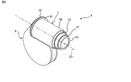
- FIG. 2 is a perspective view showing a state in which the arm portion of FIG. 1 is contracted.
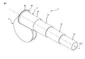
- FIG. 3 is a perspective view showing a state in which the arm portion of FIG. 1 is extended.
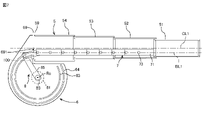
- FIG. 4 is a side view showing the internal structure of the linear motion mechanism of FIG. 2 in a state where the arm portion is excluded.
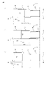
- FIG. 5 is a side view showing the position of the center of gravity when the arm portion of FIG. 4 is extended.
- FIG. 6 is a side view showing the internal structure of the linear motion mechanism when the arm portion of FIG. 2 is contracted.
- FIG. 7 is a side view showing the internal structure of the linear motion mechanism when the arm portion of FIG. 3 is extended.
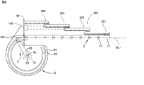
- FIG. 8 is a side view showing another example of the arm portion of FIG.
- the robot device 1 includes a polar coordinate type robot arm mechanism 2 and a control device 3 for controlling the robot arm mechanism 2.
- the robot arm mechanism 2 has a base 20 on a flat plate.
- a support frame is vertically erected on the base 20.
- the strut portion is divided into two vertically, a lower strut frame 21 and an upper strut frame 22.
- the lower strut frame 21 and the upper strut frame 22 are connected to each other so as to be rotatable left and right by a first rotary joint J1 having a rotation axis (first rotation axis RA1) perpendicular to the base 20.
- the linear motion mechanism 4 rotates up and down via a second rotary joint J2 provided with a rotary axis (second rotary axis RA2) orthogonal to the first rotary axis RA1. It is supported freely.
- the linear motion mechanism 4 includes an arm portion 5 having elasticity.
- the arm portion 5 is expandable and contractible along the linear motion axis RA3 orthogonal to the second rotation axis RA2, and constitutes the third linear motion joint J3.
- a wrist portion 9 having three rotary joints J4, J5, and J6 whose rotation axes are orthogonal to each other is connected to the tip of the arm portion 5.
- the rotary joint J4 has a rotary axis RA4 orthogonal to the linear motion axis RA3.
- the rotary joint J5 has a rotary axis RA5 perpendicular to the rotary axis RA4.
- the rotary joint J6 has a rotary shaft RA6 perpendicular to the rotary shaft RA4 and the rotary shaft RA5.
- An adapter for attaching an end effector such as a gripper is provided on the wrist portion 9.
- the arm portion 5 is composed of a fixed element and a plurality of linear motion elements assembled in multiple stages with respect to the fixed element. As shown in FIGS. 2 and 3, in the present embodiment, the arm portion 5 is composed of a plurality of cylinders 51, 52, 53, 54 assembled in a telescopic structure (multi-stage nested structure), in this case, four cylinders 51, 52, 53, 54. .. Two adjacent cylinders are slidably connected along the cylinder center line CL1 via a slider mechanism (not shown). The cylindrical center line CL1 corresponds to the linear motion axis RA3 of the third linear motion joint J3.
- the rearmost cylinder 54 is fixed to the housing 6, and the leading cylinder 51 is connected to the arm drive mechanism.
- the rearmost cylindrical body 54 fixed to the housing 6 corresponds to a fixed element, and the other cylindrical bodies 51, 52, 53 correspond to a plurality of linear motion elements, respectively.
- the cylindrical body may be a tubular body, or may be a square tubular body or the like.
- the leading cylindrical body 51 When the leading cylindrical body 51 is moved forward by the arm drive mechanism, it is pulled out from the rear cylindrical body in order from the leading cylindrical body 51, and as a result, the arm portion 5 is forward along the cylindrical center line CL1. Is stretched to.
- the leading cylinder 51 When the leading cylinder 51 is moved rearward by the arm drive mechanism, it is accommodated in the rear cylinder in order from the leading cylinder 51, and as a result, the arm portion 5 is rearward along the cylinder center line CL1. Shrinks to.
- the distance from the rearmost cylinder 54 to the head cylinder 51 is based on the control value of the arm expansion / contraction length. Can be calculated.
- the other cylindrical bodies 52, 53 excluding the leading cylindrical body 51 and the rearmost cylindrical body 54 slide through the adjacent cylindrical bodies and the slider mechanism. Since they are only movably connected, the distance from the rearmost cylindrical body 54 to the other cylindrical bodies 52 and 53 includes the undulating motion of the arm portion 5 by the robot arm mechanism 2, the turning motion of the arm portion 5, and the like. , There is a possibility that it fluctuates every time the robot arm mechanism 2 is operated.
- the distance from the last cylinder 54 to the other cylinders 52, 53 in other words, the positions of the other cylinders 52, 53 with respect to the last cylinder 54 are unique based on the control value of the arm expansion / contraction length. It may not be decided.
- the robot device 1 includes a position specifying portion for specifying the positions of the two cylinders 52 and 53 with respect to the rearmost cylinder 54.
- the robot device 1 has a 2ch specification laser displacement meter as a detection unit 100 for detecting the distance between the two cylinders 52 and 53 with respect to the rearmost cylinder 54.
- the detection unit 100 is located inside the rearmost cylinder 54, below the moving axis BL1 of the block row 70, so that the two detection axes are parallel to the cylinder center line CL1. It is attached.
- the data regarding the distance from the rearmost cylinder 54 to the cylinder 53 and the data regarding the distance from the rearmost cylinder 54 to the cylinder 52 measured by the laser displacement meter are input to the control device 3.
- the laser displacement meter measures the distance from the reference position to the cylinder 53 and the distance from the reference position to the cylinder 52.
- the above-mentioned reference position is, for example, a predetermined position in a laser displacement meter.
- the relative positional relationship between the laser displacement meter and the rearmost cylindrical body 54 is fixed.
- the amount of movement of the cylinder 53 with respect to the reference position corresponds to the distance from the rearmost cylinder 54 to the cylinder 53, and the amount of movement of the cylinder 52 with respect to the reference position is from the rearmost cylinder 54 to the cylinder 52. Corresponds to the distance of.
- the control device 3 is a task program in which a series of operations by a robot arm mechanism 2 and a robot hand (not shown) attached to the robot arm mechanism 2 is described, and a plurality of cylindrical bodies 51, 52, 53 constituting the arm unit 5.
- a position identification program that specifies the relative positional relationship of each, a center of gravity position estimation program that estimates the position of the center of gravity of the arm unit 5, a contact detection program that detects contact between a person or an object with the robot arm mechanism 2 and the like are stored. It is provided with a storage device such as an HDD, an arithmetic processing device such as a CPU that executes a program stored in the storage device, and the like.
- the arithmetic processing device functions as a position specifying unit when executing the position specifying program, and functions as a center of gravity position estimation processing unit for estimating the center of gravity position of the arm unit 5 when executing the center of gravity position estimation program, and executes the contact detection program. When doing so, it functions as a contact detection unit that detects the contact of a person or an object with the robot arm mechanism 2.
- the position specifying unit identifies the positions of the other cylinders 52 and 53 with respect to the rearmost cylinder 54 based on the distance from the detecting unit 100 detected by the detecting unit 100 to the cylinders 52 and 53.
- the positional relationship between the rearmost cylinder 54 and the detection unit 100 is fixed, and the distance between them is known. Therefore, based on the distance from the rearmost cylinder 54 to the detection unit 100 and the distance from the detection unit 100 to the cylinders 52, 53, the positions of the other cylinders 52, 53 with respect to the rearmost cylinder 54 are determined. Can be identified.
- the center of gravity position estimation processing unit includes the positions of the other cylinders 52 and 53 with respect to the rearmost cylinder 54 obtained by executing the position identification program, the positions of the head cylinder 51 with respect to the rearmost cylinder 54, and 4
- the position of the center of gravity of the arm portion 5 is estimated based on the weights of the two cylinders 51, 52, 53, 54. For example, as shown in FIG.
- the center of gravity position estimation processing unit has a distance D11 from the rearmost cylinder 54 to the cylinder 53, a distance D12 from the rearmost cylinder 54 to the cylinder 52, and The center of gravity position G1 is estimated based on the distance D13 from the last cylindrical body 54 to the cylindrical body 51 and the weight of each of the cylindrical bodies 51, 52, 53, 54.
- FIG. 5B shows a state in which the cylindrical bodies 52 and 53 have moved forward with respect to the arm portion 5 shown in FIG. 5A.
- the center of gravity position estimation processing unit is a distance D21 from the rearmost cylindrical body 54 to the cylindrical body 53, a distance D22 from the rearmost cylindrical body 54 to the cylindrical body 52, and a distance D22 from the rearmost cylindrical body 54 to the cylindrical body 51.
- FIG. 5 (c) shows a state in which the cylindrical bodies 52 and 53 have moved backward compared to the arm portion 5 shown in FIG. 5 (a).
- the center of gravity position estimation processing unit is a distance D31 from the rearmost cylindrical body 54 to the cylindrical body 53, a distance D32 from the rearmost cylindrical body 54 to the cylindrical body 52, and a distance D32 from the rearmost cylindrical body 54 to the cylindrical body 51.
- the center of gravity position G3 behind the center of gravity position G1 is estimated.
- the distance from the last cylindrical body 54 to the cylindrical body 51 can be calculated from the arm expansion / contraction length, and is assumed to be the same in FIGS. 5 (a), 5 (b), and 5 (c). ..
- the contact detection unit includes the center of gravity position of the arm unit 5 estimated by the center of gravity position estimation processing unit, the center of gravity position of each link connecting each joint portion of the robot arm mechanism 2, and the movement amount (rotation amount) of each joint portion.
- the Newton-Euler method, the Lagrange method, or the like is used to calculate the torque generated in each joint portion by the operation of the robot arm mechanism 2.
- the external force can be calculated based on the detection value of the torque sensor mounted on each joint and the calculation result of the torque generated in each joint by the operation of the robot arm mechanism 2 described above.
- the contact detection unit detects that a person or an object has come into contact with the robot arm mechanism 2 when the external force exceeds a predetermined value.
- the cylinders 52 and 53 move with respect to the rearmost cylinder 54. This may cause the position of the center of gravity of the arm portion 5 to fluctuate.
- the calculation processing by the position identification unit, the center of gravity position estimation processing unit, and the contact detection unit is based on the presence or absence of operation of the robot arm mechanism 2. Regardless, it is desirable to execute at predetermined intervals.
- the arm portion 5 is composed of a fixed element (cylindrical body 54 at the end) and a plurality of linear motion elements (cylindrical bodies 51, 52, 53) assembled in multiple stages with respect to the fixed element.
- the detection unit 100 is the position of the other linear motion element (cylindrical body 52, 53) with respect to the fixed element (the rearmost cylindrical body 54). Can be identified.
- the position of the center of gravity of the arm portion 5 can be estimated, and in the torque sensor provided in the joint portion, the force caused by the operation of the robot arm mechanism 2 and a person or an object to the robot arm mechanism 2
- the force caused by the contact can be separated, and the accuracy of contact detection can be improved.
- the laser displacement meter 100 is mounted inside the rearmost cylindrical body 54 and below the moving axis of the block row 7, but the mounting position of the laser displacement meter 100 is not limited to the present embodiment. ..
- the laser displacement meter 100 may be mounted at a position above the moving axis BL1 of the block row 7.
- the laser displacement meter 100 may be attached to the left or right position of the moving axis BL1 of the block row 7. From the viewpoint of lowering the center of gravity of the arm portion 5, it is advantageous to attach the laser displacement meter 100 to a position below the moving axis BL1 of the block row 7.
- the detection unit 100 is not limited to the laser displacement meter as long as it can measure the distance, and may be, for example, a laser reflection type distance sensor or the like.
- a single laser displacement meter having 2ch specifications is installed inside the rearmost cylinder 54 as the detection unit 100. It was mounted and configured to detect the distance from the detection unit 00 to the two cylinders 52 and 53.
- the configuration of the detection unit 100 is not limited to this as long as the relative positional relationship of each of the plurality of cylinders 51, 52, 53, 54 can be specified.
- the laser displacement meter 100 having a 2ch specification may be provided in the housing 6 to which the rearmost cylindrical body 54 is fixed.
- a 2ch specification laser displacement meter 100 is attached to the leading cylindrical body 51 to perform laser displacement.
- the distance from the total 100 to the other cylinders 52, 53 may be measured, and the position of the other cylinders 52, 53 with respect to the head cylinder 51 may be specified.
- two laser displacement meters with 1ch specifications may be used. In this case, one laser displacement meter is attached to the rearmost cylindrical body 54, the distance from the rearmost cylindrical body 54 to the cylindrical body 53 in front of the rearmost cylindrical body 54 is measured, and the other laser displacement meter is attached to the cylindrical body 53.
- the distance from the cylindrical body 53 to the cylindrical body 52 in front of the cylindrical body 53 can be measured, and from these results, the positions of the other cylindrical bodies 52 and 53 with respect to the rearmost cylindrical body 54 can be specified. From the viewpoint of suppressing the weight load by mounting the laser displacement gauge, it is advantageous to provide the laser displacement gauge in the rearmost cylindrical body 54 or the housing 6 to which the rearmost cylindrical body 54 is fixed.
- the position of the center of gravity of the arm portion 5 is estimated based on the relative positional relationship of all the cylindrical bodies 51, 52, 53, 54 constituting the arm portion 5.
- the estimation accuracy is lower than that of the above estimation process, but for example, the first cylinder 51, the last cylinder 54, and others.
- the position of the center of gravity of the arm portion 5 may be estimated based on the relative positional relationship of the three cylinders of one of the other cylinders 52 and 53.
- the laser displacement meter 100 is mounted on the first cylinder 51 or the last cylinder 54, and is configured to measure only the distance to one of the cylinders 52 and 53.
- the cylinder that has a large effect on the fluctuation of the center of gravity position, such as the heavy weight and the large fluctuation of the distance with respect to the rearmost cylinder 54, is selected as the cylinder whose position is to be specified. It is desirable to be done.
- the linear motion mechanism 4 is configured as follows.
- the arm portion 5 is supported by the housing 6.
- the housing 6 is typically configured in a substantially short cylindrical shape with an upper portion of approximately 1/4 circle cut out.
- a mount plate 69 is attached to the notch at the top of the housing 6.
- a flange 59 formed at the rear end of the arm portion 5, that is, the trailing edge of the rearmost cylindrical body 54 is joined to the mount plate 69, and is fastened with bolts or the like.
- the mount plate 69 has an opening 691.
- the inside of the housing 6 communicates with the hollow inside of the cylindrical bodies 51, 52, 53, 54 (the hollow inside of the arm portion 5).
- the block row 7 is inserted in the space communicating from the inside of the housing 6 to the inside of the cylinders 51, 52, 53, 54.
- the opening 691 serves as an entrance / exit for the block row 7 to enter / exit the housing 6.
- the block row 7 is formed by connecting a plurality of blocks 71 in a row.
- the block 71 has a rectangular parallelepiped shape, and cam followers 73 are attached to both side surfaces thereof.
- the shape of the block 71 and the connecting structure of the block 71 are such that the two adjacent blocks 71 are arranged in a straight line, and the upward rotation is restricted, but the downward rotation is allowed. It is composed of.
- the first block 71 of the block row 7 is connected to the first cylinder 51 among the plurality of cylinders 51, 52, 53, 54. Most of the block row 7 is housed inside the housing 6 in a state where the arm portion 5 is contracted. Typically, inside the housing 6, the block rows 7 are housed in an arc shape centered on the housing center Rc. Therefore, a pair of guide rails 63 and 64 are provided on the inner surfaces of both side plates of the housing 6 as accommodating portions for accommodating the block row 7 along the arc track.
- the pair of guide rails 63, 64 is configured as a linear body curved in an arc shape, the center of the arc coincides with the center Rc of the housing, and the guide surface of the outer guide rail 64 and the inner side of the guide rail 64.
- the distance between the guide rail 63 and the guide surface is configured to be equivalent to the diameter of the cam follower 73 mounted on the block 71 or slightly larger than the diameter of the cam follower.
- the block row drive mechanism 8 includes a motor (not shown) and a speed reducer 81 that reduces the rotational speed of the motor.
- the speed reducer 81 is arranged so that the rotation center of the rotation shaft 83 coincides with the housing center Rc.
- One end (base end) of the rod-shaped rotary arm 85 is connected to the rotary shaft 83 of the speed reducer 81.
- the other end (tip) of the rotary arm 85 is connected to the rearmost block 71.
- the block row 7 is pushed out by the rotating arm 35, and the leading block 71 is moved forward along the moving axis BL1 parallel to the cylindrical center line CL1.
- the leading block 71 moves forward, it is pulled out from the rear cylindrical body in order from the leading cylindrical body 51, and as a result, the arm portion 5 extends forward along the cylindrical center line CL1.
- the block row 7 is pulled back by the rotating arm 35, and the leading block 71 is moved backward along the moving axis BL1 parallel to the cylindrical center line CL1.
- the leading block 71 moves backward, it is accommodated in the rear cylindrical body in order from the leading cylindrical body 51, and as a result, the arm portion 5 is retracted rearward along the cylindrical center line CL1.
- the block row 7 and the block row drive mechanism 8 for driving the movement of the block row 7 constitute an arm drive mechanism for driving the front-back movement of the leading cylindrical body 51, that is, the expansion and contraction of the arm portion 5. ..
- the block row 7 is pushed out and pulled back by the rotary arm 85 to drive the movement of the leading cylinder 51, but if the movement of the leading cylinder 51 can be driven, the arm drive mechanism can be used.
- the configuration is not limited to this embodiment.
- the block row 7 is sent out from the housing 6 and pulled back to the housing 6 by engaging the gear formed in the block 71 with the drive gear provided on the moving track of the block row 7. You may do it.
- the movement of the leading cylindrical body 51 may be driven by an existing linear motion mechanism such as a ball screw mechanism.
- the arm portion 5 is not limited to the telescopic structure.
- the arm portion 800 may be configured by a plurality of vertically continuous linear motion guide mechanisms 801, 802, 803, 804.
- Each of the linear motion guide mechanisms 801, 802, 803, 804 is composed of a linear guide supported by a base and a moving body capable of sliding the linear guide.
- the base that supports the linear guide of the rearmost linear motion guide mechanism 804 is fixed to the mount plate 69 of the housing, and the leading linear motion guide mechanism 801 moves.
- the first block 71 of the block row 7 is connected to the body (slider).
- the arm unit 800 expands and contracts with respect to the rearmost linear motion guide mechanism 804 as the block row 7 other than the first linear motion guide mechanism 801 moves back and forth along the movement axis BL1. Will be done. Only the structure of the arm portion is different, and even if the linear motion expansion / contraction mechanism adopts the arm portion 800 composed of a plurality of linear motion guide mechanisms 801, 802, 803, 804, it is the same as the arm portion 5 adopting the telescopic structure. Play the effect of.
Landscapes
- Engineering & Computer Science (AREA)
- Robotics (AREA)
- Mechanical Engineering (AREA)
- Physics & Mathematics (AREA)
- Optics & Photonics (AREA)
- Manipulator (AREA)
Abstract
Description
アーム部5は筐体6に支持される。図4に示すように、典型的には、筐体6は、上部の略1/4円の範囲が切り欠かれた略短円筒形に構成される。筐体6の上部の切り欠き箇所にはマウント板69が取り付けられる。マウント板69にはアーム部5の後端、すなわち最後尾の円筒体54の後縁に形成されたフランジ59が接合され、ボルト等により締結される。マウント板69には、開口691があけられている。それにより、筐体6の内部が円筒体51,52,53,54の中空内部(アーム部5の中空内部)と連通する。図6、図7に示すように、筐体6の内部から円筒体51,52,53,54の内部にわたって連通する空間にはブロック列7が挿入されている。開口691はブロック列7が筐体6を出入りするための出入り口となる。
Claims (6)
- 固定要素と前記固定要素に対して伸縮自在に多段に組まれる複数の直動要素とを有するアーム部と、
前記複数の直動要素のうち先頭の直動要素の移動を駆動する移動駆動機構と、
前記固定要素又は前記先頭の直動要素に対する、前記複数の直動要素のうち前記先頭の直動要素を除く少なくとも一の直動要素の位置を特定する位置特定部と、
を具備するロボット装置。 - 前記位置特定部は、前記固定要素に対する前記複数の直動要素のうち前記先頭の直動要素を除く全ての直動要素各々の距離を検出するセンサを有する、請求項1記載のロボット装置。
- 前記センサは、前記固定要素又は前記固定要素を支持する支持部材に取り付けられる、請求項2記載のロボット装置。
- 前記固定要素に対する前記先頭の直動要素の位置と前記特定された位置との組み合わせに基づいて前記アーム部の重心位置を推定する重心推定処理部をさらに具備する、請求項1乃至3のいずれか一項に記載のロボット装置。
- 前記アーム部は、多段入れ子構造に組まれた複数の筒状体により構成される、請求項1乃至4のいずれか一項に記載のロボット装置。
- 前記アーム部は、複数のリニアガイドと前記リニアガイドに沿って移動する複数の移動体とにより構成される、請求項1乃至4のいずれか一項に記載のロボット装置。
Priority Applications (4)
| Application Number | Priority Date | Filing Date | Title |
|---|---|---|---|
| DE112021005181.4T DE112021005181T5 (de) | 2020-12-22 | 2021-12-15 | Robotervorrichtung |
| CN202180082916.4A CN116600956A (zh) | 2020-12-22 | 2021-12-15 | 机器人装置 |
| US18/039,584 US12569994B2 (en) | 2020-12-22 | 2021-12-15 | Robot apparatus |
| JP2022572219A JP7502471B2 (ja) | 2020-12-22 | 2021-12-15 | ロボット装置 |
Applications Claiming Priority (2)
| Application Number | Priority Date | Filing Date | Title |
|---|---|---|---|
| JP2020-212453 | 2020-12-22 | ||
| JP2020212453 | 2020-12-22 |
Publications (1)
| Publication Number | Publication Date |
|---|---|
| WO2022138368A1 true WO2022138368A1 (ja) | 2022-06-30 |
Family
ID=82159186
Family Applications (1)
| Application Number | Title | Priority Date | Filing Date |
|---|---|---|---|
| PCT/JP2021/046230 Ceased WO2022138368A1 (ja) | 2020-12-22 | 2021-12-15 | ロボット装置 |
Country Status (6)
| Country | Link |
|---|---|
| US (1) | US12569994B2 (ja) |
| JP (1) | JP7502471B2 (ja) |
| CN (1) | CN116600956A (ja) |
| DE (1) | DE112021005181T5 (ja) |
| TW (1) | TWI889945B (ja) |
| WO (1) | WO2022138368A1 (ja) |
Cited By (1)
| Publication number | Priority date | Publication date | Assignee | Title |
|---|---|---|---|---|
| WO2025041250A1 (ja) * | 2023-08-22 | 2025-02-27 | ファナック株式会社 | ロボットの制御装置、制御方法およびロボットシステム |
Citations (2)
| Publication number | Priority date | Publication date | Assignee | Title |
|---|---|---|---|---|
| JPH02269591A (ja) * | 1989-04-10 | 1990-11-02 | Toshiba Corp | ロボット |
| CN108724247A (zh) * | 2018-07-04 | 2018-11-02 | 湖北三江航天涂装设备工程有限公司 | 用于扩大机器人动作范围的高精度伸缩臂及其控制方法 |
Family Cites Families (6)
| Publication number | Priority date | Publication date | Assignee | Title |
|---|---|---|---|---|
| JPS6169708A (ja) | 1984-09-13 | 1986-04-10 | Pola Chem Ind Inc | 化粧料 |
| JPH023518Y2 (ja) | 1985-05-31 | 1990-01-26 | ||
| US5214749A (en) * | 1991-06-12 | 1993-05-25 | Massachusetts Institute Of Technology | Dynamic control of a robot with its center of mass decoupled from an end effector by a redundant linkage |
| CN102514550B (zh) | 2011-12-20 | 2014-04-30 | 长沙中联消防机械有限公司 | 工程机械以及其安全状态确定方法、装置和系统 |
| CN104608125B (zh) * | 2013-11-01 | 2019-12-17 | 精工爱普生株式会社 | 机器人、控制装置以及机器人系统 |
| TWM591907U (zh) * | 2019-11-12 | 2020-03-11 | 正崴精密工業股份有限公司 | 多軸機械手臂 |
-
2021
- 2021-12-09 TW TW110146002A patent/TWI889945B/zh active
- 2021-12-15 DE DE112021005181.4T patent/DE112021005181T5/de active Pending
- 2021-12-15 WO PCT/JP2021/046230 patent/WO2022138368A1/ja not_active Ceased
- 2021-12-15 CN CN202180082916.4A patent/CN116600956A/zh active Pending
- 2021-12-15 JP JP2022572219A patent/JP7502471B2/ja active Active
- 2021-12-15 US US18/039,584 patent/US12569994B2/en active Active
Patent Citations (2)
| Publication number | Priority date | Publication date | Assignee | Title |
|---|---|---|---|---|
| JPH02269591A (ja) * | 1989-04-10 | 1990-11-02 | Toshiba Corp | ロボット |
| CN108724247A (zh) * | 2018-07-04 | 2018-11-02 | 湖北三江航天涂装设备工程有限公司 | 用于扩大机器人动作范围的高精度伸缩臂及其控制方法 |
Cited By (1)
| Publication number | Priority date | Publication date | Assignee | Title |
|---|---|---|---|---|
| WO2025041250A1 (ja) * | 2023-08-22 | 2025-02-27 | ファナック株式会社 | ロボットの制御装置、制御方法およびロボットシステム |
Also Published As
| Publication number | Publication date |
|---|---|
| US12569994B2 (en) | 2026-03-10 |
| JP7502471B2 (ja) | 2024-06-18 |
| TWI889945B (zh) | 2025-07-11 |
| CN116600956A (zh) | 2023-08-15 |
| US20240091937A1 (en) | 2024-03-21 |
| DE112021005181T5 (de) | 2023-09-14 |
| TW202227240A (zh) | 2022-07-16 |
| JPWO2022138368A1 (ja) | 2022-06-30 |
Similar Documents
| Publication | Publication Date | Title |
|---|---|---|
| KR102435320B1 (ko) | 자율 이동 반송 로봇 | |
| US9943967B2 (en) | Five-degree-of-freedom hybrid robot with rotational supports | |
| KR102475955B1 (ko) | 다관절 아암 로봇에 부착된 보링 공구를 사용하여 고정식으로 장착된 공작물의 표면에 보어홀을 도입하기 위한 방법 및 장치 | |
| US8948904B2 (en) | Work picking system | |
| US10406697B2 (en) | Robot arm mechanism | |
| EP3326037B1 (en) | System and method for determining tool offsets | |
| US20190126468A1 (en) | Mobile robot | |
| CN111975250A (zh) | 工件旋转装置和机器人系统 | |
| JPWO2018025725A1 (ja) | ロボットアーム機構 | |
| WO2016181801A1 (ja) | ロボットシステム | |
| CZ2012798A3 (cs) | Zařízení pro měření polohy koncového efektoru, zvláště manipulátoru nebo obráběcího stroje | |
| US20220193929A1 (en) | Holding device and robot provided with same | |
| WO2022138368A1 (ja) | ロボット装置 | |
| CN109803798B (zh) | 机械臂机构 | |
| WO2018062070A1 (ja) | ロボットアーム機構、ロボットハンド及びエンドエフェクタカバー | |
| WO2024101413A1 (ja) | 商品移動装置、その制御方法及びコンピュータプログラム | |
| KR200492381Y1 (ko) | 다각도로 작동 가능한 선형 모듈 | |
| JP7035963B2 (ja) | 搬送装置と工作機械 | |
| JP6783474B2 (ja) | テーブル駆動装置及び該テーブル駆動装置を具備した作業システム | |
| US20250170725A1 (en) | Robot system | |
| CN215709461U (zh) | 一种基于直线运动的高精度位置定位器 | |
| RU2263571C1 (ru) | Промышленный робот | |
| KR102350196B1 (ko) | 이송 장치 | |
| WO2023233468A1 (ja) | 把持機構、ロボット | |
| CN121290361A (zh) | 一种基于并联臂与视觉伺服的精密装配机器人机构 |
Legal Events
| Date | Code | Title | Description |
|---|---|---|---|
| 121 | Ep: the epo has been informed by wipo that ep was designated in this application |
Ref document number: 21910516 Country of ref document: EP Kind code of ref document: A1 |
|
| ENP | Entry into the national phase |
Ref document number: 2022572219 Country of ref document: JP Kind code of ref document: A |
|
| WWE | Wipo information: entry into national phase |
Ref document number: 112021005181 Country of ref document: DE |
|
| WWE | Wipo information: entry into national phase |
Ref document number: 18039584 Country of ref document: US |
|
| WWE | Wipo information: entry into national phase |
Ref document number: 202180082916.4 Country of ref document: CN |
|
| 122 | Ep: pct application non-entry in european phase |
Ref document number: 21910516 Country of ref document: EP Kind code of ref document: A1 |
|
| WWG | Wipo information: grant in national office |
Ref document number: 18039584 Country of ref document: US |