WO2022138211A1 - 発光モジュール及びレンズ - Google Patents
発光モジュール及びレンズ Download PDFInfo
- Publication number
- WO2022138211A1 WO2022138211A1 PCT/JP2021/045390 JP2021045390W WO2022138211A1 WO 2022138211 A1 WO2022138211 A1 WO 2022138211A1 JP 2021045390 W JP2021045390 W JP 2021045390W WO 2022138211 A1 WO2022138211 A1 WO 2022138211A1
- Authority
- WO
- WIPO (PCT)
- Prior art keywords
- lens
- light
- light source
- rotation axis
- emitted
- Prior art date
- Legal status (The legal status is an assumption and is not a legal conclusion. Google has not performed a legal analysis and makes no representation as to the accuracy of the status listed.)
- Ceased
Links
Images


Classifications
-
- H—ELECTRICITY
- H10—SEMICONDUCTOR DEVICES; ELECTRIC SOLID-STATE DEVICES NOT OTHERWISE PROVIDED FOR
- H10H—INORGANIC LIGHT-EMITTING SEMICONDUCTOR DEVICES HAVING POTENTIAL BARRIERS
- H10H20/00—Individual inorganic light-emitting semiconductor devices having potential barriers, e.g. light-emitting diodes [LED]
- H10H20/80—Constructional details
- H10H20/85—Packages
- H10H20/855—Optical field-shaping means, e.g. lenses
-
- F—MECHANICAL ENGINEERING; LIGHTING; HEATING; WEAPONS; BLASTING
- F21—LIGHTING
- F21V—FUNCTIONAL FEATURES OR DETAILS OF LIGHTING DEVICES OR SYSTEMS THEREOF; STRUCTURAL COMBINATIONS OF LIGHTING DEVICES WITH OTHER ARTICLES, NOT OTHERWISE PROVIDED FOR
- F21V14/00—Controlling the distribution of the light emitted by adjustment of elements
- F21V14/02—Controlling the distribution of the light emitted by adjustment of elements by movement of light sources
-
- F—MECHANICAL ENGINEERING; LIGHTING; HEATING; WEAPONS; BLASTING
- F21—LIGHTING
- F21V—FUNCTIONAL FEATURES OR DETAILS OF LIGHTING DEVICES OR SYSTEMS THEREOF; STRUCTURAL COMBINATIONS OF LIGHTING DEVICES WITH OTHER ARTICLES, NOT OTHERWISE PROVIDED FOR
- F21V14/00—Controlling the distribution of the light emitted by adjustment of elements
- F21V14/06—Controlling the distribution of the light emitted by adjustment of elements by movement of refractors
-
- F—MECHANICAL ENGINEERING; LIGHTING; HEATING; WEAPONS; BLASTING
- F21—LIGHTING
- F21V—FUNCTIONAL FEATURES OR DETAILS OF LIGHTING DEVICES OR SYSTEMS THEREOF; STRUCTURAL COMBINATIONS OF LIGHTING DEVICES WITH OTHER ARTICLES, NOT OTHERWISE PROVIDED FOR
- F21V5/00—Refractors for light sources
- F21V5/007—Array of lenses or refractors for a cluster of light sources, e.g. for arrangement of multiple light sources in one plane
-
- F—MECHANICAL ENGINEERING; LIGHTING; HEATING; WEAPONS; BLASTING
- F21—LIGHTING
- F21V—FUNCTIONAL FEATURES OR DETAILS OF LIGHTING DEVICES OR SYSTEMS THEREOF; STRUCTURAL COMBINATIONS OF LIGHTING DEVICES WITH OTHER ARTICLES, NOT OTHERWISE PROVIDED FOR
- F21V5/00—Refractors for light sources
- F21V5/04—Refractors for light sources of lens shape
- F21V5/045—Refractors for light sources of lens shape the lens having discontinuous faces, e.g. Fresnel lenses
-
- F—MECHANICAL ENGINEERING; LIGHTING; HEATING; WEAPONS; BLASTING
- F21—LIGHTING
- F21V—FUNCTIONAL FEATURES OR DETAILS OF LIGHTING DEVICES OR SYSTEMS THEREOF; STRUCTURAL COMBINATIONS OF LIGHTING DEVICES WITH OTHER ARTICLES, NOT OTHERWISE PROVIDED FOR
- F21V7/00—Reflectors for light sources
- F21V7/0091—Reflectors for light sources using total internal reflection
-
- G—PHYSICS
- G02—OPTICS
- G02B—OPTICAL ELEMENTS, SYSTEMS OR APPARATUS
- G02B19/00—Condensers, e.g. light collectors or similar non-imaging optics
- G02B19/0004—Condensers, e.g. light collectors or similar non-imaging optics characterised by the optical means employed
- G02B19/0028—Condensers, e.g. light collectors or similar non-imaging optics characterised by the optical means employed refractive and reflective surfaces, e.g. non-imaging catadioptric systems
-
- G—PHYSICS
- G02—OPTICS
- G02B—OPTICAL ELEMENTS, SYSTEMS OR APPARATUS
- G02B19/00—Condensers, e.g. light collectors or similar non-imaging optics
- G02B19/0033—Condensers, e.g. light collectors or similar non-imaging optics characterised by the use
- G02B19/0047—Condensers, e.g. light collectors or similar non-imaging optics characterised by the use for use with a light source
- G02B19/0061—Condensers, e.g. light collectors or similar non-imaging optics characterised by the use for use with a light source the light source comprising a LED
- G02B19/0066—Condensers, e.g. light collectors or similar non-imaging optics characterised by the use for use with a light source the light source comprising a LED in the form of an LED array
-
- G—PHYSICS
- G03—PHOTOGRAPHY; CINEMATOGRAPHY; ANALOGOUS TECHNIQUES USING WAVES OTHER THAN OPTICAL WAVES; ELECTROGRAPHY; HOLOGRAPHY
- G03B—APPARATUS OR ARRANGEMENTS FOR TAKING PHOTOGRAPHS OR FOR PROJECTING OR VIEWING THEM; APPARATUS OR ARRANGEMENTS EMPLOYING ANALOGOUS TECHNIQUES USING WAVES OTHER THAN OPTICAL WAVES; ACCESSORIES THEREFOR
- G03B15/00—Special procedures for taking photographs; Apparatus therefor
- G03B15/02—Illuminating scene
- G03B15/03—Combinations of cameras with lighting apparatus; Flash units
- G03B15/05—Combinations of cameras with electronic flash apparatus; Electronic flash units
-
- H—ELECTRICITY
- H10—SEMICONDUCTOR DEVICES; ELECTRIC SOLID-STATE DEVICES NOT OTHERWISE PROVIDED FOR
- H10H—INORGANIC LIGHT-EMITTING SEMICONDUCTOR DEVICES HAVING POTENTIAL BARRIERS
- H10H29/00—Integrated devices, or assemblies of multiple devices, comprising at least one light-emitting semiconductor element covered by group H10H20/00
- H10H29/80—Constructional details
- H10H29/85—Packages
- H10H29/855—Optical field-shaping means, e.g. lenses
-
- H—ELECTRICITY
- H10—SEMICONDUCTOR DEVICES; ELECTRIC SOLID-STATE DEVICES NOT OTHERWISE PROVIDED FOR
- H10W—GENERIC PACKAGES, INTERCONNECTIONS, CONNECTORS OR OTHER CONSTRUCTIONAL DETAILS OF DEVICES COVERED BY CLASS H10
- H10W90/00—Package configurations
-
- F—MECHANICAL ENGINEERING; LIGHTING; HEATING; WEAPONS; BLASTING
- F21—LIGHTING
- F21Y—INDEXING SCHEME ASSOCIATED WITH SUBCLASSES F21K, F21L, F21S and F21V, RELATING TO THE FORM OR THE KIND OF THE LIGHT SOURCES OR OF THE COLOUR OF THE LIGHT EMITTED
- F21Y2113/00—Combination of light sources
- F21Y2113/10—Combination of light sources of different colours
- F21Y2113/13—Combination of light sources of different colours comprising an assembly of point-like light sources
-
- F—MECHANICAL ENGINEERING; LIGHTING; HEATING; WEAPONS; BLASTING
- F21—LIGHTING
- F21Y—INDEXING SCHEME ASSOCIATED WITH SUBCLASSES F21K, F21L, F21S and F21V, RELATING TO THE FORM OR THE KIND OF THE LIGHT SOURCES OR OF THE COLOUR OF THE LIGHT EMITTED
- F21Y2115/00—Light-generating elements of semiconductor light sources
- F21Y2115/10—Light-emitting diodes [LED]
Definitions
- This disclosure relates to a light emitting module and a lens.
- a housing that holds a plurality of semiconductor light emitting elements a housing that holds a plurality of semiconductor light emitting elements so that the optical axes of their respective emitted lights face the same direction, and a housing that displaces the housing along a plane intersecting the optical axes.
- a lighting device including a driving means is disclosed. By rotating the housing around the axis extending in the direction orthogonal to the above-mentioned plane at the substantially center of the plurality of semiconductor light emitting elements, the light emitted from the plurality of semiconductor light emitting elements is mixed in the subject, and the semiconductor light emitting element is a single unit. The color temperature and uneven lighting caused by individual differences are eliminated. In this lighting device, the light distribution pattern is constant (see, for example, Patent Document 1).
- the light emitting module includes a first light source unit having a first light source, a first lens to which light emitted from the first light source is incident, and a drive capable of rotating the first lens.
- a unit and a control unit that controls the output of the first light source in conjunction with the drive unit are provided, and the central axis of light emitted from the first lens is inclined with respect to the rotation axis of the first lens. is doing.
- the lens according to the embodiment of the present disclosure is a lens that can rotate about a rotation axis by an external drive unit, and can emit light having an optical axis inclined with respect to the rotation axis.
- the light emitting module is provided so as to be paired with a substrate, a plurality of light sources arranged on the substrate, and each of the plurality of light sources, and light emitted from the plurality of light sources is emitted.
- the plurality of light source units With the plurality of light source units having the plurality of incident lenses, the substrate, and the plurality of light source units fixed, the plurality of light source units can be rotated in conjunction with the drive unit and the drive unit.
- a control unit capable of controlling the output of each of the plurality of light sources is provided.
- the number of lenses capable of irradiating light on the orbit of the first irradiation region centered on the rotation axis of the plurality of light source units is the number of lenses in the first irradiation region centered on the rotation axis. It is less than the number of lenses that can irradiate light on the orbit of the second irradiation region located outside the orbit.
- FIG. 3 is a partial cross-sectional view taken along the line II-II of FIG. 2 is an enlarged cross-sectional view showing a part of the first light source unit, the second light source unit, and the substrate in FIG. 2. It is sectional drawing which shows the 1st light source unit and the other example of the 2nd light source unit. It is a cross-sectional view which shows the 3rd light source unit, the 4th light source unit, and a part of a substrate enlarged in the cross section of FIG. 1 in line IV-IV. It is sectional drawing which shows the 3rd light source unit and the other example of the 4th light source unit.
- FIG. 5 is an enlarged cross-sectional view showing a plurality of light source units and a substrate in the cross section taken along line XIX-XIX in FIG.
- FIG. 5 is an enlarged cross-sectional view showing a plurality of light source units and a substrate in the cross section taken along the line XX-XX of FIG.
- It is a figure which shows the irradiation area of the light emitted from each light source unit in the plane orthogonal to the axial direction.
- It is a schematic diagram for demonstrating the setting method of the angle formed by the central axis and the rotation axis of the light emitted from each light source unit.
- It is a schematic diagram which shows the light emitting module, the camera and the screen which concerns on Example.
- the embodiments shown below exemplify a light emitting module for embodying the technical idea of the present invention, and the present invention is not limited to the embodiments shown below.
- the dimensions, materials, shapes, relative arrangements, etc. of the components described below are not intended to limit the scope of the present invention to the specific description, but are intended to be exemplified. It is a thing.
- the size and positional relationship of the members shown in the drawings may be exaggerated in order to clarify the explanation.
- the direction may be indicated by the X-axis, Y-axis, and Z-axis, but the X-direction along the X-axis is the plane on which the light source included in the light emitting module according to the embodiment is arranged (hereinafter, also referred to as the arrangement plane).
- the Y direction along the Y axis indicates the direction orthogonal to the X direction in the arrangement plane of the light source, and the Z direction along the Z axis indicates the direction orthogonal to the arrangement plane of the light source. It shall be shown.
- the direction in which the arrow points in the X direction is referred to as the + X direction, the opposite direction in the + X direction is referred to as the -X direction, the direction in which the arrow points in the Y direction is referred to as the + Y direction, and the opposite direction in the + Y direction is referred to as the -Y direction.
- the direction in which the arrow points in the Z direction is referred to as the + Z direction
- the direction opposite to the + Z direction is referred to as the ⁇ Z direction.
- the plurality of light sources irradiate light in the + Z direction as an example. However, this does not limit the orientation when the light emitting module is used, and the orientation of the light emitting module is arbitrary.
- the top view means to see the object from the + Z direction side.
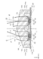
- FIG. 1 is a top view showing a light emitting module according to the present embodiment.
- FIG. 2 is a partial cross-sectional view taken along line II-II of FIG.
- the light emitting module 100 includes a first light source unit 110, a drive unit 160, and a control unit 170, which is outlined with reference to FIG.
- the first light source unit 110 includes a first light source 111 and a first lens 112 to which light emitted from the first light source 111 is incident.
- the drive unit 160 can rotate the first lens 112.
- “the drive unit can rotate the first lens” means that the drive unit rotates the first lens itself on an axis parallel to the Z axis, or the drive unit is attached to the first lens. Either the component may be rotated on an axis parallel to the Z axis. Then, when the first lens is rotated, other components may be rotated along the axis parallel to the Z axis together with the first lens.
- the drive unit 160 rotates the substrate 150 to which the first lens 112 is attached on an axis parallel to the Z axis to provide a first light source unit 110 including the first lens 112. Rotate.
- the control unit 170 controls the output of the first light source 111 in conjunction with the drive unit 160.
- the first lens 112 is rotated by a rotation axis C parallel to the Z axis
- the central axis f1 of the light L1 emitted from the first lens 112 is the rotation axis C (in other words, the rotation axis C) of the first lens 112. It is tilted with respect to the Z axis).
- the "central axis of light emitted from the first lens” is a position a1 at which the illuminance of the light emitted from the first lens 112 is maximum on any plane P1 orthogonal to the Z axis, and is separated from the plane P1 in the + Z direction. , Means a straight line passing through the position a2 where the illuminance of light is maximized on any other plane P2 orthogonal to the Z axis.
- the central axis of light is the optical axis.
- the first lens 112 is a lens that can rotate about the rotation axis C by an external drive unit 160, and emits light L1 having an optical axis f1 inclined with respect to the rotation axis C. It is possible.
- the central axis of the light emitted from the first lens is inclined with respect to the rotation axis of the first lens
- the central axis of the light emitted from the first lens is the first lens. It means that it has an inclination with respect to the rotation axis of.
- the straight line extending the central axis of the light emitted from the first lens and the straight line extending the rotation axis of the first lens may have an intersection point or may be a twisted position. The same applies to the second lens, the third lens, and the fourth lens described below.
- the light emitting module 100 further includes a second light source unit 120, a third light source unit 130, a fourth light source unit 140, and a substrate 150.
- the second light source unit 120 has a second light source 121 and a second lens 122 to which the light emitted from the second light source 121 is incident.
- the third light source unit 130 has a third light source 131 and a third lens 132 to which the light emitted from the third light source 131 is incident.
- the fourth light source unit 140 has a fourth light source 141 and a fourth lens 142 to which the light emitted from the fourth light source 141 is incident.
- a first light source unit 110, a second light source unit 120, a third light source unit 130, and a fourth light source unit 140 are attached to the substrate 150.
- each part of the light emitting module 100 will be described in detail.
- the substrate 150 has a base material made of an insulating material such as a resin material, and a plurality of wirings 151 connected to the light sources 111, 121, 131, 141 inside the substrate 150. Is a wiring board provided with.
- the surface of the substrate 150 includes an upper surface 150a and a lower surface 150b located on the opposite side of the upper surface 150a.
- the upper surface 150a and the lower surface 150b are orthogonal to the Z axis.
- the upper surface 150a is an arrangement plane of the light sources 111, 121, 131, 141.
- the top view shape of the top surface 150a is circular.
- the center of the top surface 150a is located on the rotation axis C.
- the shape of the substrate 150 in the top view is not limited to the above, and may be a polygon such as a quadrangle. Further, the center of the upper surface 150a does not have to be located on the rotation axis C.
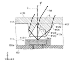
- FIG. 3A is an enlarged cross-sectional view showing the first light source unit and the second light source unit in FIG. 2, and a part of the substrate.
- FIG. 3B is a cross-sectional view showing another example of the first light source unit and the second light source unit.
- FIG. 4A is an enlarged cross-sectional view showing a third light source unit, a fourth light source unit, and a part of a substrate in the cross section taken along the line IV-IV of FIG.
- FIG. 4B is a cross-sectional view showing another example of the third light source unit and the fourth light source unit.
- four light sources 111, 121, 131, and 141 are attached to the upper surface 150a.
- the number of light sources attached to the upper surface 150a is not limited to the above as long as it is 1 or more.
- the number of light sources attached to the upper surface 150a may be 1 to 3, or 5 or more.
- Each light source 111, 121, 131, 141 includes a light emitting element 181, a wavelength conversion member 182, and a light reflecting member 183 in the present embodiment.
- the light emitting element 181 is, for example, an LED (Light Emitting Diode).
- the light emitting device 181 has at least a semiconductor laminate and a pair of positive and negative electrodes 184.
- the semiconductor material it is preferable to use a nitride semiconductor, which is a material capable of emitting short wavelength light capable of efficiently exciting a wavelength conversion substance contained in the wavelength conversion member.
- Nitride semiconductors are mainly represented by the general formula In x Al y Ga 1-xy N (0 ⁇ x, 0 ⁇ y, x + y ⁇ 1).
- the emission peak wavelength of the light emitting element is preferably 400 nm or more and 530 nm or less, more preferably 420 nm or more and 490 nm or less, and more preferably 450 nm or more and 475 nm or less from the viewpoint of luminous efficiency, excitation of the wavelength converting substance and the color mixing relationship with the emission thereof. More preferable. Further, as the semiconductor material, an InAlGaAs-based semiconductor, an InAlGaP-based semiconductor, or the like can also be used.
- the electrodes 184 in the light emitting element 181 are electrically connected to the wiring 151 in the substrate 150, respectively. The color of the light emitted from the light emitting element 181 is blue in this embodiment.
- the wavelength conversion member 182 is arranged on the light emitting element 181.
- the wavelength conversion member 182 contains a wavelength conversion substance using a resin such as silicone as a base material.
- the wavelength conversion substance is a member that absorbs at least a part of the primary light emitted by the light emitting element 181 and emits secondary light having a wavelength different from that of the primary light.
- Examples of the wavelength conversion substance include an yttrium-aluminum-garnet-based phosphor (for example, Y3 ( Al, Ga) 5 O 12 : Ce) and a lutetium-aluminum-garnet-based phosphor (for example, Lu 3 (Al, Ga)).
- ⁇ -sialon phosphor for example, M z (Si, Al) 12 (O, N) 16 (where 0 ⁇ z ⁇ 2 and M is Li, Mg, Ca, Y, and La.
- nitride-based phosphors such as CASN-based phosphors (eg, CaAlSiN 3 : Eu) or SCASN-based phosphors (eg, (Sr, Ca) AlSiN 3 : Eu), KSF-based fluorescence Fluoride-based phosphors such as body (eg, K 2 SiF 6 : Mn) or MGF-based phosphors (eg, 3.5 MgO, 0.5 MgF 2 , GeO 2 : Mn), CCA-based phosphors (eg, (Ca) , Sr) 10 (PO 4 ) 6 Cl 2 : Eu), or quantum dots such as sulfide-based phosphors, perovskite, and calcopyrite can be used.
- CASN-based phosphors eg, CaAlSiN 3 : Eu
- SCASN-based phosphors eg, (Sr, Ca) AlSiN 3 : Eu
- the wavelength conversion substance one of these fluorescent substances can be used alone, or two or more of these fluorescent substances can be used in combination.
- the color emitted by the wavelength conversion member 182 is, for example, yellow.
- Each of the light sources 111, 121, 131, 141 emits white light by mixing the blue color of the light emitted from the light emitting element 181 and the yellow color of the light emitted from the wavelength conversion member 182.
- the white resin containing a white pigment such as titanium oxide and magnesium oxide in the base material of the light reflecting member 183 is preferable.
- the base material of the light-reflecting member 183 include resins such as silicone, epoxy, phenol, polycarbonate, and acrylic, or modified resins thereof.
- the light reflecting member 183 covers at least the side surfaces of the light emitting element 181 and the wavelength conversion member 182.
- the upper surface of the wavelength conversion member 182 (the region not covered by the light reflective member 183 of the wavelength conversion member 182) is the light emitting surface (in other words, the light emitting surface) of each of the light sources 111, 121, 131, 141.
- each light source 111, 121, 131, 141 is not limited to the above.
- the wavelength conversion member 182 in each of the light sources 111, 121, 131, 141 emits green light by wavelength-converting a red phosphor that converts blue light to emit red light and emits green light by wavelength-converting blue light. It may contain a green phosphor.
- each of the light sources 111, 121, 131, 141 can emit white light by mixing the blue color of the light emitted from the light emitting element 181 and the red color and the green color of the light emitted from the wavelength conversion member 182.
- the wavelength conversion member 182 may not be provided on one or more of the four light sources 111, 121, 131, and 141.
- the shapes of the light sources 111, 121, 131, and 141 in the top view are quadrangular, but the shape is not limited thereto.
- the shape of each light source 111, 121, 131, 141 in the top view may be a polygon such as a triangle or a circle.
- the first light source 111, the second light source 121, the third light source 131, and the fourth light source 141 are arranged on the circumference e centered on the rotation axis C.
- the center c1 of the first light source 111, the center c4 of the fourth light source 141, the center c2 of the second light source 121, and the center c3 of the third light source 131 are centered on the rotation axis C. It is located clockwise on the circumference e in this order.
- the center c1 is located at the intersection of the diagonal lines of the first light source 111 in the top view.
- the positions of the light sources 111, 121, 131, 141 are not limited to the above.
- the four light sources 111, 121, 131, 141 may be arranged along the X direction or the Y direction of the upper surface 150a of the substrate 150.
- the first lens 112 is arranged in the + Z direction of the first light source 111, and the second lens 122 is arranged in the + Z direction of the second light source 121.
- the third lens 132 is arranged in the + Z direction of the third light source 131, and the fourth lens 142 is arranged in the + Z direction of the fourth light source 141.
- the first lens 112, the second lens 122, the third lens 132, and the fourth lens 142 are integrally connected as one translucent member 185 by being connected on the surface side from which light is emitted. Is formed in.
- the first lens 112 is a lens including a total reflection surface that totally reflects light in the present embodiment. Specifically, the first lens 112 has a total reflection surface that totally reflects light inside the first lens 112. Therefore, the light emitted from the first light source 111 can be condensed or collimated by the first lens 112 and projected.
- the half-width full-width of the light emitted from the first lens 112 is, for example, 15 degrees.
- the surface of the first lens 112 includes a first surface 112a, a second surface 112b, a third surface 112c, and a fourth surface 112f.
- the thick solid arrow in FIG. 3A exemplifies the path of light.
- the first surface 112a faces the first light source 111. Light emitted from the first light source 111 is incident on the first surface 112a. The first surface 112a is in contact with the first region 112d curved convexly toward the first light source 111 and the outer edge of the first region 112d, and extends from the outer edge of the first region 112d toward the first light source 111. Includes region 112e and.
- the shape of the outer circumference of the first region 112d and the outer circumference of the second region 112e in the top view is a quadrangle with rounded corners.
- the center of the first region 112d in the top view is located on the center c1 of the first light source 111.
- an axis that passes through the center c1 and is parallel to the rotation axis C (in other words, the Z axis) is referred to as a “central axis g1”.
- the second region 112e is inclined so as to be separated from the central axis g1 toward the ⁇ Z direction.
- the light emitting surface of the first light source 111 is in the X direction or Y of the first region 112d. It is preferably between the two lower ends in the direction, and more preferably the first light source 111 is between the two lower ends in the X or Y direction of the first region 112d, as shown in FIG. 3B.
- the second surface 112b is provided around the first surface 112a.
- the second surface 112b is inclined so as to approach the central axis g1 toward the ⁇ Z direction.
- the second surface 112b reflects at least a part of the light incident on the first lens 112 from the first surface 112a toward the inside of the first lens 112.
- the second surface 112b corresponds to a total reflection surface.
- the third surface 112c is located on the opposite side of the first surface 112a.
- the third surface 112c emits at least a part of the light incident on the first lens 112 from the first surface 112a.
- the third surface 112c is a flat surface.
- the flat surface (upper surface) of the third surface 112c approaches the substrate 150 as the distance from the rotation axis C increases. Therefore, the direction H1 perpendicular to the third surface 112c is inclined with respect to the rotation axis C (in other words, the central axis g1) at an angle ⁇ 1a so as to move away from the rotation axis C toward the + Z direction.
- the central axis f1 of the light emitted from the first lens 112 is tilted at an angle ⁇ 1b with respect to the rotation axis C (in other words, the central axis g1) so as to approach the rotation axis C toward the + Z direction.
- the fourth surface 112f is provided around the second surface 112b.
- the fourth surface 112f is parallel to the upper surface 150a of the substrate 150.
- the fourth surface 112f does not have to be parallel to the upper surface 150a of the substrate 150.
- the second lens 122 is a lens including a total reflection surface that totally reflects light in the present embodiment. Specifically, the second lens 122 has a total reflection surface that totally reflects light inside the second lens 122. Therefore, the second lens 122 can collect or collimate the light emitted from the second light source 121 and project it.
- the half-width full-width of the light emitted from the second lens 122 is, for example, 15 degrees.
- the surface of the second lens 122 includes a first surface 122a, a second surface 122b, a third surface 122c, and a fourth surface 122f.
- the first surface 122a faces the second light source 121.
- the light emitted from the second light source 121 is incident on the first surface 122a.
- the second surface 122b is in contact with the outer edge of the first region 122d and the first region 122d that is convexly curved toward the second light source 121, and extends from the outer edge of the first region 122d toward the second light source 121. Includes region 122e.
- the shape of the outer circumference of the first region 122d and the outer circumference of the second region 122e in the top view is a quadrangle with rounded corners.
- the center of the first region 122d in the top view is located on the center c2 of the second light source 121.
- an axis that passes through the center c2 and is parallel to the rotation axis C (in other words, the Z axis) is referred to as a “central axis g2”.
- the second region 122e is inclined so as to be separated from the central axis g2 toward the ⁇ Z direction.
- the light emitting surface of the second light source 121 is in the X direction or Y of the first region 122d. It is preferably between the two lower ends in the direction, and more preferably between the two lower ends in the X or Y direction of the first region 122d, as shown in FIG. 3B.
- the second surface 122b is provided around the first surface 122a.
- the second surface 122b is inclined so as to approach the central axis g2 toward the ⁇ Z direction.
- the second surface 122b reflects at least a part of the light incident on the second lens 122 from the first surface 122a toward the inside of the second lens 122.
- the second surface 122b corresponds to a total reflection surface.
- the third surface 122c is located on the opposite side of the first surface 122a.
- the third surface 122c emits at least a part of the light incident on the second lens 122 from the first surface 122a.
- the third surface 122c is a flat surface.
- the flat surface (upper surface) of the third surface 122c approaches the substrate 150 as the distance from the rotation axis C increases. Therefore, the direction H2 perpendicular to the third surface 122c is inclined with respect to the rotation axis C (in other words, the central axis g2) at an angle ⁇ 2a so as to move away from the rotation axis C toward the + Z direction.
- the central axis f2 of the light emitted from the second lens 122 is tilted at an angle ⁇ 2b with respect to the rotation axis C (in other words, the central axis g2) so as to approach the rotation axis C toward the + Z direction.
- the fourth surface 122f is provided around the second surface 122b.
- the fourth surface 122f is parallel to the upper surface 150a of the substrate 150.
- the translucent member 185 has a convex portion protruding in the + Z direction due to the third surface 112c of the first lens 112 and the third surface 122c of the second lens 122.
- the fourth surface 112f of the first lens 112 and the fourth surface 122f of the second lens 122 are flush with each other.
- the third lens 132 is a lens including a total reflection surface that totally reflects light in the present embodiment.
- the third lens 132 has a total reflection surface that totally reflects light inside the third lens 132. Therefore, the light emitted from the third light source 131 can be condensed or collimated and projected by the third lens 132.
- the half-width full-width of the light emitted from the third lens 132 is, for example, 15 degrees.
- the surface of the third lens 132 includes a first surface 132a, a second surface 132b, a third surface 132c, and a fourth surface 132f.
- the thick solid arrow in FIG. 4A exemplifies the path of light.
- the first surface 132a faces the third light source 131.
- the light emitted from the third light source 131 is incident on the first surface 132a.
- the first surface 132a is in contact with the first region 132d that is convexly curved toward the third light source 131 and the outer edge of the first region 132d, and extends from the outer edge of the first region 132d toward the third light source 131. Includes region 132e and.
- the shape of the outer circumference of the first region 132d and the outer circumference of the second region 132e in the top view is a quadrangle with rounded corners.
- the center of the first region 132d in the top view is located on the center c3 of the third light source 131.
- an axis that passes through the center c3 and is parallel to the rotation axis C (in other words, the Z axis) is referred to as a “central axis g3”.
- the second region 132e is inclined so as to be separated from the central axis g3 toward the ⁇ Z direction.
- the light emitting surface of the third light source 131 is in the X direction or Y of the first region 132d. It is preferably between the two lower ends in the direction, and more preferably between the two lower ends in the X or Y direction of the first region 132d, as shown in FIG. 4B.
- the second surface 132b is provided around the first surface 132a.
- the second surface 132b is inclined so as to approach the central axis g3 toward the ⁇ Z direction.
- the second surface 132b reflects at least a part of the light incident on the third lens 132 from the first surface 132a toward the inside of the third lens 132.
- the second surface 132b corresponds to a total reflection surface.
- the third surface 132c is located on the opposite side of the first surface 132a.
- the third surface 132c emits at least a part of the light incident on the third lens 132 from the first surface 132a.
- the third surface 132c is a flat surface.
- the flat surface (upper surface) of the third surface 132c approaches the substrate 150 as the distance from the rotation axis C increases. Therefore, the direction H3 perpendicular to the third surface 132c is inclined with respect to the rotation axis C (in other words, the central axis g3) at an angle ⁇ 3a so as to move away from the rotation axis C toward the + Z direction.
- the central axis f3 of the light emitted from the third lens 132 is tilted at an angle ⁇ 3b with respect to the rotation axis C (in other words, the central axis g3) so as to approach the rotation axis C toward the + Z direction.
- the fourth surface 132f is provided around the second surface 132b.
- the fourth surface 132f is parallel to the upper surface 150a of the substrate 150.
- the fourth surface 132f is flush with the fourth surface 112f of the first lens 112 and the fourth surface 122f of the second lens 122, and is in contact with them.
- the fourth lens 142 is a lens including a total reflection surface that totally reflects light in the present embodiment. Specifically, the fourth lens 142 has a total reflection surface that totally reflects light inside the fourth lens 142. Therefore, the light emitted from the fourth light source 141 can be condensed or collimated and projected by the fourth lens 142.
- the half-width full-width of the light emitted from the fourth lens 142 is, for example, 15 degrees.
- the surface of the fourth lens 142 includes a first surface 142a, a second surface 142b, a third surface 142c, and a fourth surface 142f.
- the first surface 142a faces the fourth light source 141. Light emitted from the fourth light source 141 is incident on the first surface 142a.
- the second surface 142b is in contact with the first region 142d that is convexly curved toward the fourth light source 141 and the outer edge of the first region 142d, and extends from the outer edge of the first region 142d toward the fourth light source 141. Includes region 142e and.
- the shape of the outer circumference of the first region 142d and the outer circumference of the second region 142e in the top view is a quadrangle with rounded corners.
- the center of the first region 142d in the top view is located on the center c4 of the fourth light source 141.
- an axis that passes through the center c4 and is parallel to the rotation axis C (in other words, the Z axis) is referred to as a “central axis g4”.
- the second region 142e is inclined so as to be separated from the central axis g4 toward the ⁇ Z direction.
- the light emitting surface of the fourth light source 141 is in the X direction or Y of the first region 142d. It is preferably between the two lower ends in the direction, and more preferably between the two lower ends in the X or Y direction of the first region 142d, as shown in FIG. 4B.
- the second surface 142b is provided around the first surface 142a.
- the second surface 142b is inclined so as to approach the central axis g4 toward the ⁇ Z direction.
- the second surface 142b reflects at least a part of the light incident on the fourth lens 142 from the first surface 142a toward the inside of the fourth lens 142.
- the second surface 142b corresponds to a total reflection surface.
- the third surface 142c is located on the opposite side of the first surface 142a.
- the third surface 142c emits at least a part of the light incident on the fourth lens 142 from the first surface 142a.
- the third surface 142c is a flat surface.
- the flat surface (upper surface) of the third surface 142c approaches the substrate 150 as the distance from the rotation axis C increases. Therefore, the direction H4 perpendicular to the third surface 142c is inclined with respect to the rotation axis C (in other words, the central axis g4) at an angle ⁇ 4a so as to move away from the rotation axis C toward the + Z direction.
- the central axis f4 of the light emitted from the fourth lens 142 is tilted at an angle ⁇ 4b with respect to the rotation axis C (in other words, the central axis g4) so as to approach the rotation axis C toward the + Z direction.
- the fourth surface 142f is provided around the second surface 142b.
- the fourth surface 142f is parallel to the upper surface 150a of the substrate 150.
- the fourth surface 142f is flush with the fourth surface 112f of the first lens 112 and the fourth surface 122f of the second lens 122, and is in contact with them.
- the translucent member 185 has a convex portion protruding in the + Z direction due to the third surface 132c of the third lens 132 and the third surface 142c of the fourth lens 142.
- the third surface 112c of the first lens 112 is in contact with the third surface 132c of the third lens 132 and the third surface 142c of the fourth lens 142.
- the third surface 122c of the second lens 122 is in contact with the third surface 132c of the third lens 132 and the third surface 142c of the fourth lens 142.
- the angles ⁇ 1a, the angle ⁇ 2a, the angle ⁇ 3a, and the angle ⁇ 4a are different from each other, and the angle ⁇ 3a ⁇ angle ⁇ 2a ⁇ angle ⁇ 4a ⁇ angle ⁇ 1a. Therefore, the angle ⁇ 3b ⁇ angle ⁇ 2b ⁇ angle ⁇ 4b ⁇ angle ⁇ 1b.
- the third surface 112c of the first lens 112, the third surface 122c of the second lens 122, the third surface 132c of the third lens 132, and the third surface 142c of the fourth lens 142 are the rotation axes C (or Z), respectively. Since the inclination angle with respect to the axis) can be appropriately adjusted, the magnitude relationship between the angle ⁇ 1a, the angle ⁇ 2a, the angle ⁇ 3a, and the angle ⁇ 4a is not limited to the above.
- the third surface 112c of the first lens 112, the third surface 122c of the second lens 122, the third surface 132c of the third lens 132, and the third surface 142c of the fourth lens 142 are flat surfaces, respectively.
- the present invention is not limited to this as long as the central axes f1, f2, f3, and f4 of the light emitted from the lens are inclined with respect to the rotation axis C.
- the center c1 of the first light source 111 may be deviated from the center of the first region 112d.
- the center c1 of the first light source 111 is the first region 112d in the top view.
- the first light source 111 is separated from the second lens 122 as compared with the case where it is located on the center of. As a result, it is possible to suppress the light emitted from the first light source 111 from entering the first lens 112 and then heading toward the third surface 122c of the second lens 122.
- the first light source 111 when the first light source 111 is separated from the second lens 122, the light emitted from the first light source 111 enters the first lens 112 and then heads toward the third surface 122c of the second lens 122. It can be suppressed. As a result, the generation of such stray light can be suppressed.
- the positional relationship between the second lens 122 and the second light source 121, the positional relationship between the third lens 132 and the third light source 131, and the positional relationship between the fourth lens 142 and the fourth light source 141 may be similarly configured. ..
- the rotation axes C, Z axis and the central axes g1, g2, g3, and g4 are parallel to each other. Therefore, in the first embodiment, even if the straight line extending the central axis f1 of the light emitted from the first lens 112 and the straight line extending the rotation axis C of the first lens 112 have an intersection, they are twisted. Even at the position of, "the angle formed by the central axis f1 of the light emitted from the first lens 112 and the rotation axis C" is formed by "the central axis f1 and the Z axis of the light emitted from the first lens 112".
- a support portion 187 extending toward the substrate 150 is provided on the outer peripheral portion of the translucent member 185.
- the support portion 187 is fixed to the upper surface 150a of the substrate 150.
- the support portion 187 holds the lenses 112, 122, 132, 142 away from the light sources 111, 121, 131, 141.
- the support portion 187 has a cylindrical shape that surrounds the periphery of the first lens 112, the second lens 122, the third lens 132, and the fourth lens 142 in the present embodiment.
- the support portion 187 is not limited to the tubular shape, and a plurality of columnar support portions may be arranged on the outer periphery of the translucent member 185. Further, the support portion may be formed of a member different from the translucent member 185. In this case, the support portion does not have to have translucency.
- the translucent member 185 does not have to be the one in which the four lenses 112, 122, 132, 142 are integrally formed.
- the lenses 112, 122, 132, 142 which are made of different materials or have different refractive indexes, may be bonded together by an adhesive or the like.
- the lenses 112, 122, 132, 142 made of different materials or having different refractive indexes may be individually attached to the upper surface 150a of the substrate 150 without being bonded to each other.
- the drive unit 160 rotates the substrate 150 on an axis parallel to the Z axis to form a first light source unit 110, a second light source unit 120, and a third light source unit 130. And the fourth light source unit 140 is rotated.
- the drive unit 160 has a motor 161 and a shaft 162 that is connected to the substrate 150 and interlocks with the motor 161.
- the shaft 162 rotates.
- the substrate 150 and the translucent member 185 (each lens 112, 122, 132, 142) fixed to the substrate 150 rotate around the rotation axis C parallel to the Z axis.
- the shaft 162 is provided with a rotary connector 190 having a ring unit 191 and a brush unit 192.
- the rotary connection connector 190 is a slip ring in this embodiment.
- the rotary connection connector 190 electrically connects a plurality of wirings 151 built in the rotating substrate 150 to the control unit 170.
- the ring unit 191 has a tubular body 191a in which a shaft 162 is arranged inside and is connected to the shaft 162, and a plurality of conductive rings 191b provided on the outer periphery of the tubular body 191a.
- the ring unit 191 rotates with the shaft 162.
- a plurality of rings 191b and a plurality of wirings 151 built in the substrate 150 are electrically connected one-to-one via the inside of the shaft 162 and the inside of the cylindrical body 191a.
- the brush unit 192 has a plurality of conductive brushes 192a that come into contact with each of the plurality of rings 191b, and a holder 192b that holds the plurality of brushes 192a.
- the plurality of brushes 192a are individually electrically connected to the control unit 170.
- FIG. 2 simply shows the connection relationship between the control unit 170 and the rotary connection connector 190 with a single line.
- the control unit 170 and the brush unit 192 do not rotate.
- the control unit 170 and the brush unit 192 are fixed to the housing of the smartphone or the like. Therefore, when the motor 161 is driven, the brush unit 192 can transmit an electric signal to the ring unit 191 without rotating.
- the light emitting module 100 does not have to be used as a light source for the flash of the smartphone.
- the configuration of the rotary connection connector 190 is not limited to the above.
- the rotary connector 190 may be a rotary connector using liquid metal or the like.
- the control unit 170 has, for example, a CPU (Central Processing Unit), a memory, and the like.
- the control unit 170 is electrically connected to the motor 161 in the drive unit 160.
- the control unit 170 controls the motor 161 to rotate the substrate 150 on the rotation axis C.
- the rotation speed of the substrate 150 is not particularly limited, but is, for example, 60 rpm or more and 24000 rpm or less.
- the rotation speed of the substrate 150 is, for example, 14000 rpm.
- the control unit 170 may be configured so that the rotation speed of the motor 161 can be adjusted.
- the control unit 170 individually controls the outputs of the four light sources 111, 121, 131, and 141. "Controlling the output” includes turning on the light source, turning off the light source, and adjusting the brightness of the light emitted from the light source when the light source is turned on. Specifically, the control unit 170 individually adjusts the amount of current supplied to the light sources 111, 121, 131, 141 via the rotary connector 190 to output the light sources 111, 121, 131, 141. Is controlled individually.
- the control unit 170 controls the output of the first light source 111 according to the position in the circumferential orbit of the central axis f1 of the light emitted from the first lens 112 when the substrate 150 is rotated by the rotation axis C. Further, the control unit 170 controls the output of the second light source 121 according to the position in the circumferential orbit of the central axis f2 of the light emitted from the second lens 122 when the substrate 150 is rotated by the rotation axis C. do. Further, the control unit 170 controls the output of the third light source 131 according to the position in the circumferential orbit of the central axis f3 of the light emitted from the third lens 132 when the substrate 150 is rotated by the rotation axis C. do.
- control unit 170 controls the output of the fourth light source 141 according to the position in the circumferential orbit of the central axis f4 of the light emitted from the fourth lens 142 when the substrate 150 is rotated by the rotation axis C. do.
- the control unit 170 is, for example, a position on the orbit of each light central axis f1, f2, f3, f4 from the position before rotation of each lens 112, 122, 132, 142 and the rotation speed and rotation speed of the motor 161. May be estimated. Further, the control unit 170 may estimate the position on the orbit of the central axes f1, f2, f3, and f4 of each light by using the detection result of the rotation angle detection sensor such as the rotary encoder. Specifically, the rotation angle detection sensor detects the amount of rotation (rotation angle) of the substrate 150 from the reference state, with the state in which the substrate 150 is not rotating as a reference state. Then, the positions of the central axes f1, f2, f3, and f4 of the light during rotation can be estimated from the rotation angle of the substrate 150 from the reference state.
- FIG. 5 is a diagram showing the positions of light emitted from each light source unit in a plane orthogonal to the Z axis.
- FIG. 6 is a diagram showing the positions and trajectories of light emitted from each light source unit in a plane orthogonal to the Z axis.
- the trajectory of the central axis f3 of the light L3 emitted from the third lens 132 is located at a position away from the rotation axis C on one plane P3 orthogonal to the Z axis.
- the orbit of the central axis f2 of the light L2 emitted from the second lens 122 is located on the plane P3 at a position farther from the rotation axis C than the position of the orbit of the central axis f3.
- the orbit of the central axis f4 of the light L4 emitted from the fourth lens 142 is located at a position farther from the rotation axis C than the position of the orbit of the central axis f2 on the plane P3.
- the orbit of the central axis f1 of the light L1 emitted from the first lens 112 is located on the plane P3 at a position farther from the rotation axis C than the position of the orbit of the central axis f4.
- each light source unit 110, 120, 130, 140 also makes one rotation around the rotation axis C.
- the central axis f3 in the third light source unit 130 moves on the plane P3 on the orbit e3 on the circumference centered on the rotation axis C.
- the central axis f2 in the second light source unit 120 moves on the plane P3 with the rotation axis C as the center and on the orbit e2 having a radius larger than the orbit e3.
- the central axis f4 in the fourth light source unit 140 moves on the plane P3 with the rotation axis C as the center and on the orbit e4 having a radius larger than the orbit e2.
- the central axis f1 in the first light source unit 110 moves on the plane P3 with the rotation axis C as the center and on the orbit e1 having a radius larger than the orbit e4.
- control unit 170 realizes various light distribution patterns by controlling the outputs of the light sources 111, 121, 131, 141 according to the positions of the central axes f1, f2, f3, and f4 in the rotation direction. can do.
- the region to which the light L1 emitted from the first light source unit 110 is irradiated when the substrate 150 is rotated once on the rotation axis C with the first light source 111 turned on is referred to as “the first irradiation region h1”. ". Further, the region where the light L2 emitted from the second light source unit 120 is irradiated when the substrate 150 is rotated once on the rotation axis C with the second light source 121 turned on is defined as the “second irradiation region h2”. ".
- the region where the light L1 emitted from the third light source unit 130 is irradiated when the substrate 150 is rotated once on the rotation axis C with the third light source 131 turned on is defined as the “third irradiation region h3”. ".
- the region to which the light L4 emitted from the fourth light source unit 140 is irradiated when the substrate 150 is rotated once on the rotation axis C with the fourth light source 141 turned on is referred to as "fourth irradiation region h4". ..
- FIG. 6 it is a region irradiated with light by each of the light source units 110, 120, 130, 140 (that is, a first irradiation region h1, a second irradiation region h2, a third irradiation region h3, and a fourth irradiation region h4. , Hereinafter, these are collectively referred to as “irradiation area”), which is shown in a one-to-one relationship, in which the light emitted from each light source unit actually irradiates only the corresponding irradiation area. Not limited to.
- the irradiation area corresponding to each light source unit is an area targeted by each light source unit.
- the light emitted from one light source unit may also illuminate at least a part of the adjacent irradiation area. That is, although FIG. 6 shows an example in which adjacent irradiation regions do not overlap, the adjacent irradiation regions may partially overlap.
- the first irradiation region h1, the second irradiation region h2, and the fourth irradiation region h4 are annular in the present embodiment.
- the third irradiation region h3 is circular. As described above, the smaller the angle formed by the central axis of light and the axis of rotation, the closer the irradiation region is from an annular shape to a circular shape.
- the central axes f1, f2, f3, and f4 of the lights L1, L2, L3, and L4 emitted from all the lenses 112, 122, 132, and 142 are inclined with respect to the rotation axis C.
- the central axis of the light emitted from at least one lens may be inclined with respect to the rotation axis C.
- the light emitting module may include a lens that emits light whose central axis is parallel to the axis of rotation C. The trajectory of the central axis on the plane P3 of the light emitted from such a lens is located inside the trajectory of the light whose central axis is inclined with respect to the rotation axis C.
- the orbit of the central axis of the light emitted from such a lens is a circumferential orbit, but in the plane P3, the irradiation region of the light emitted from such a lens is the third irradiation region shown in FIG. Similar to h3, it becomes circular.
- FIG. 7A is a schematic diagram illustrating the light distribution pattern of the light source of the flash according to the reference example.
- FIG. 7B is a schematic diagram illustrating photographs taken with the light distribution pattern shown in FIG. 7A.
- FIG. 8A is a schematic diagram illustrating a light distribution pattern when the light emitting module 100 according to the present embodiment is applied to a light source of a flash.
- FIG. 8B is a schematic diagram illustrating photographs taken with the light distribution pattern shown in FIG. 8A.
- FIG. 7A in a flash light source (light distribution pattern A11) in which the light distribution pattern is always constant, for example, the central portion of the light distribution pattern has the highest illuminance. Therefore, as shown in FIG. 7B, in the photograph A12 taken with the light distribution pattern A11, the subject S1 in the vicinity of the light source of the flash becomes bright, and the subject S2 in the distance of the light source of the flash becomes dark. As a result, in the photograph A12, the subject S1 near the light source of the flash may be overexposed, and the subject S2 far away from the light source of the flash may be underexposed. In such a flash light source in which the light distribution pattern is always constant, a phenomenon that gradation is lost may occur.
- the light distribution pattern can be adjusted according to the distance between each subject S1 and S2 and the light emitting module 100.
- the light emitting module 100 emits a light distribution pattern A21 such that the illuminance of the subject S1 is lower than the illuminance of the subject S2.
- the illuminance in the entire third irradiation region h3, the region below the second irradiation region h2, the region below the fourth irradiation region h4, and the region below the first irradiation region h1. is lower than the illuminance in other regions in the light distribution pattern A21.
- FIG. 8C is a cross-sectional view in a state where the light emitting module according to the present embodiment is mounted on a smartphone.
- a cover member 910 having translucency may be provided above (+ Z direction) the lenses 112, 122, 132, 142.
- the lenses 112, 122, 132 are prevented from coming into contact with the rotating lenses 112, 122, 132, 142 by the user of the device.
- 142 it is preferable to provide a translucent cover member 910 above (+ Z direction).
- Such a cover member 910 is attached to a housing 920 of a device such as a smartphone.
- the cover member 910 is made of a translucent material such as glass or polycarbonate resin.
- the housing 920 is made of, for example, a resin (for example, a polycarbonate resin) or a metal containing a light diffusing material such as titanium oxide or a light absorbing material such as a black pigment.
- the light emitted from each lens 112, 122, 132, 142 travels in the direction toward the rotation axis C. Therefore, the light emitted from the lenses 112, 122, 132, and 142 is likely to enter the cover member 910. As a result, it is possible to prevent the light emitted from the lenses 112, 122, 132, 142 from being blocked by the housing 920 or the like.
- the light emitting module 100 can rotate the first light source unit 110 having the first light source 111 and the first lens 112 to which the light emitted from the first light source 111 is incident, and the first lens 112. It includes a drive unit 160 and a control unit 170 that controls the output of the first light source 111 in conjunction with the drive unit 160.
- the central axis f1 of the light L1 emitted from the first lens 112 is inclined with respect to the rotation axis C of the first lens 112. Therefore, one light source unit 110 can irradiate a wide area with light.
- the light distribution pattern can be changed by controlling the output of the first light source 111 in conjunction with the drive unit 160 by the control unit 170. Therefore, it is possible to realize a light emitting module that can change the light distribution pattern. Moreover, even if the number of light sources is small, the light distribution pattern can be changed.
- the drive unit 160 can rotate the first light source unit 110 around the rotation axis C. By rotating the first light source 111 together with the first lens 112 in this way, the light emitting module 100 can have a simple structure.
- the light emitting module 100 has a second light source unit 120 having a second light source 121 and a second lens 122 into which the light emitted from the second light source 121 is incident, and the first light source unit 110 and the second light source unit 120.
- the substrate 150 to which the light source is attached is provided.
- the drive unit 160 can rotate the second light source unit 120 together with the first light source unit 110 on the rotation axis C by rotating the substrate 150 on the rotation axis C.
- the control unit 170 controls the output of the second light source 121 in conjunction with the drive unit 160.
- the central axis f2 of the light L2 emitted from the second lens 122 is inclined with respect to the rotation axis C.
- the angle (angle ⁇ 2b) formed by the central axis f2 of the light L2 emitted from the second lens 122 and the rotation axis C is the central axis f1 of the light L1 emitted from the first lens 112 and the rotation axis. It is different from the angle (angle ⁇ 1b) formed by C (in other words, the central axis g1). Therefore, various light distribution patterns can be realized by the two light source units 110 and 120.
- first light source unit 110 and the second light source unit 120 are on the circumference of the substrate 150 about the rotation axis C. Therefore, the light emitting module 100 can be made compact.
- control unit 170 controls the output of the first light source 111 according to the position in the orbit of the circumference of the central axis f1 of the light emitted from the first lens 112. Therefore, various light distribution patterns can be realized.
- the first lens 112 is a lens including a total reflection surface that totally reflects light.
- the first lens 112 is provided around the first surface 112a on which the light emitted from the first light source 111 is incident and the first surface 112a, and is at least the light incident on the first lens 112 from the first surface 112a. It has a second surface 112b that reflects a part of the surface, and a third surface 112c that is located on the opposite side of the first surface 112a and emits light incident from the first surface 112a.
- the first lens 112 can collect or collimate the light emitted from the first light source 111 and project it.
- the direction H1 orthogonal to the third surface 112c of the first lens 112 is inclined with respect to the Z axis.
- the central axis f1 of the light L1 emitted from the first lens 112 is tilted with respect to the rotation axis C by a simple configuration in which the third surface 112c of the first lens 112 is tilted with respect to the rotation axis C. Can be done.
- the angles formed by the central axis and the rotation axis C of the light emitted from each of the first lens 112, the second lens 122, the third lens 132, and the fourth lens 142 are different from each other.
- the angle formed by the central axis f1 of the light emitted from the first lens 112 and the rotation axis C and the angle formed by the central axis f2 of the light emitted from the second lens 122 and the rotation axis C are the same. But it may be.
- the first irradiation region h1 and the second irradiation region h2 overlap each other.
- the light emitting module 100 is adjusted by using white light as the light emitted from the first light source 111 and white light having a color temperature different from that of the light emitted from the first light source 111 as the light emitted from the second light source 121. It can emit colored light. Further, in this case, the angle formed by the central axis f3 of the light emitted from the third lens 132 and the rotation axis C is different from the angle formed by the central axis f1 of the light emitted from the first lens 112 and the rotation axis C. Moreover, the angle formed by the central axis f4 and the rotation axis C of the light emitted from the fourth lens 142 may be the same.
- the third irradiation region h3 and the fourth irradiation region h4 overlap each other. Therefore, the color of the light emitted from the third light source 131 is the same as the color of the light emitted from the first light source 111, and the color of the light emitted from the fourth light source 141 is the same as the color of the light emitted from the second light source 121. By doing so, various light distribution patterns can be realized while emitting toned light from the light source module 100.
- FIG. 9 is a top view showing a light emitting module according to the present embodiment.
- FIG. 10 is an enlarged cross-sectional view showing a first light source unit, a second light source unit, and a part of a substrate in the cross section taken along line XX of FIG.
- FIG. 11 is an enlarged cross-sectional view showing a third light source unit, a fourth light source unit, and a part of the substrate in the cross section taken along the line XI-XI of FIG.
- the light emitting module 200 according to the present embodiment is different from the light emitting module 100 according to the first embodiment in the configuration of the first lens 212, the second lens 222, the third lens 232, and the fourth lens 242.
- the differences from the first embodiment will be mainly described. Except for the matters described below, the same as in the first embodiment. This point shall be the same in each embodiment and modification shown below.
- the light emitting module 200 includes a first light source unit 210, a second light source unit 220, a third light source unit 230, and a fourth light source unit 240.
- the first light source unit 210 includes a first light source 111 and a first lens 212 to which light emitted from the first light source 111 is incident.
- the second light source unit 220 includes a second light source 121 and a second lens 222 into which the light emitted from the second light source 121 is incident.
- the third light source unit 230 has a third light source 131 and a third lens 232 to which the light emitted from the third light source 131 is incident.
- the fourth light source unit 240 has a fourth light source 141 and a fourth lens 242 to which the light emitted from the fourth light source 141 is incident.
- the four lenses 212, 222, 232, and 242 are integrally formed as one translucent member 385 by being connected to each other on the surface side from which light is emitted.
- the first lens 212 is arranged in the + Z direction of the first light source 111.
- the first lens 212 is a lens including a total reflection surface that totally reflects light in the present embodiment.
- the first lens 212 has a total reflection surface that totally reflects light inside the first lens 212.
- the surface of the first lens 212 includes a first surface 212a, a second surface 212b, a third surface 212c, and a fourth surface 212f.
- the solid arrow exemplifies the path of light.
- the configuration of the first surface 212a is the same as the configuration of the first surface 112a of the first lens 112 in the first embodiment
- the configuration of the second surface 212b is the configuration of the first lens 112 in the first embodiment. Since the configuration of the second surface 112b is the same as the configuration of the fourth surface 112f and the configuration of the fourth surface 214f is the same as the configuration of the fourth surface 112f of the first lens 112 in the first embodiment, these description will be omitted.
- the third surface 212c is located on the opposite side of the first surface 212a.
- the third surface 212c emits at least a part of the light incident on the first lens 212 from the first surface 212a.
- the third surface 212c is a flat surface.
- the flat surface (upper surface) of the third surface 212c is separated from the substrate 150 as the distance from the rotation axis C increases. Therefore, the direction H21 perpendicular to the third surface 212c is inclined with respect to the rotation axis C at an angle ⁇ 21a so as to approach the rotation axis C toward the + Z direction.
- most of the light propagating in the first lens 212 is tilted at an angle ⁇ 21b with respect to the rotation axis C so as to move away from the rotation axis C toward the + Z direction when emitted from the third surface 212c. Refract in the direction. That is, the central axis f21 of the light emitted from the first lens 212 is inclined at an angle ⁇ 21b with respect to the rotation axis C so as to be separated from the rotation axis C toward the + Z direction.
- the second lens 222 is arranged in the + Z direction of the second light source 121.
- the second lens 222 is a lens including a total reflection surface that totally reflects light in the present embodiment.
- the second lens 222 has a total reflection surface that totally reflects light inside the second lens 222.
- the surface of the second lens 222 includes a first surface 222a, a second surface 222b, a third surface 222c, and a fourth surface 222f.
- the configuration of the first surface 222a is the same as the configuration of the first surface 122a of the second lens 122 in the first embodiment
- the configuration of the second surface 222b is the configuration of the second lens 122 in the first embodiment. Since the configuration of the two surfaces 122b is the same as the configuration of the fourth surface 122f of the second lens 122 in the first embodiment, the description thereof will be omitted.
- the third surface 222c is located on the opposite side of the first surface 222a.
- the third surface 222c emits at least a part of the light incident on the second lens 222 from the first surface 222a.
- the third surface 222c is a flat surface.
- the flat surface (upper surface) of the third surface 222c is separated from the substrate 150 as the distance from the rotation axis C increases. Therefore, the direction H22 perpendicular to the third surface 222c is inclined with respect to the rotation axis C at an angle ⁇ 22a so as to approach the rotation axis C toward the + Z direction.
- most of the light propagating into the second lens 222 is tilted at an angle ⁇ 22b with respect to the rotation axis C so as to move away from the rotation axis C toward the + Z direction when emitted from the third surface 222c. Refract in the direction. That is, the central axis f22 of the light emitted from the second lens 222 is tilted at an angle ⁇ 22b with respect to the rotation axis C so as to be separated from the rotation axis C toward the + Z direction.
- the third surface 212c of the first lens 212 and the third surface 222c of the second lens 222 form a concave portion recessed in the ⁇ Z direction in the translucent member 385.
- the third lens 232 is arranged in the + Z direction of the third light source 131.
- the third lens 232 is a lens including a total reflection surface that totally reflects light in the present embodiment.
- the third lens 232 has a total reflection surface that totally reflects light inside.
- the surface of the third lens 232 includes a first surface 232a, a second surface 232b, a third surface 232c, and a fourth surface 232f.
- the solid arrow exemplifies the path of light.
- the configuration of the first surface 232a is the same as the configuration of the first surface 132a of the third lens 132 in the first embodiment
- the configuration of the second surface 232b is the configuration of the third lens 132 in the first embodiment. Since the configuration of the second surface 132b is the same as the configuration of the fourth surface 132f and the configuration of the fourth surface 232f is the same as the configuration of the fourth surface 132f of the third lens 132 in the first embodiment, these description will be omitted.
- the third surface 232c is located on the opposite side of the first surface 232a.
- the third surface 232c emits at least a part of the light incident on the third lens 232 from the first surface 232a.
- the third surface 232c is a flat surface.
- the flat surface (upper surface) of the third surface 232c is separated from the substrate 150 as the distance from the rotation axis C increases. Therefore, the direction H23 perpendicular to the third surface 232c is inclined with respect to the rotation axis C at an angle ⁇ 23a so as to approach the rotation axis C toward the + Z direction.
- the fourth lens 242 is arranged in the + Z direction of the fourth light source 141.
- the fourth lens 242 is a lens including a total reflection surface that totally reflects light in the present embodiment.
- the fourth lens 242 has a total reflection surface that totally reflects light inside the fourth lens 242.
- the surface of the fourth lens 242 includes a first surface 242a, a second surface 242b, a third surface 242c, and a fourth surface 242f.
- the configuration of the first surface 242a is the same as the configuration of the first surface 142a of the fourth lens 142 in the first embodiment
- the configuration of the second surface 242b is the configuration of the fourth lens 142 in the first embodiment. Since the configuration of the second surface 142b is the same as that of the fourth surface 142f and the configuration of the fourth surface 242f is the same as that of the fourth surface 142f of the fourth lens 142 in the first embodiment, the description thereof will be omitted.
- the third surface 242c is located on the opposite side of the first surface 242a.
- the third surface 242c emits at least a part of the light incident on the fourth lens 242 from the first surface 242a.
- the third surface 242c is a flat surface.
- the flat surface (upper surface) of the third surface 242c is separated from the substrate 150 as the distance from the rotation axis C increases. Therefore, the direction H24 perpendicular to the third surface 242c is inclined with respect to the rotation axis C at an angle ⁇ 24a so as to approach the rotation axis C toward the + Z direction.
- most of the light propagating into the fourth lens 242 is tilted at an angle ⁇ 24b with respect to the rotation axis C so as to move away from the rotation axis C toward the + Z direction when emitted from the third surface 242c. Refract in the direction. That is, the central axis f24 of the light emitted from the fourth lens 242 is tilted at an angle ⁇ 24b with respect to the rotation axis C so as to be separated from the rotation axis C toward the + Z direction.
- the translucent member 385 is formed with a recess recessed in the ⁇ Z direction due to the third surface 232c of the third lens 232 and the third surface 242c of the fourth lens 242.
- the angles ⁇ 21a, the angle ⁇ 22a, the angle ⁇ 23a, and the angle ⁇ 24a are different from each other, and the angle ⁇ 23a ⁇ angle ⁇ 22a ⁇ angle ⁇ 24a ⁇ angle ⁇ 21a. Therefore, the angle ⁇ 23b ⁇ angle ⁇ 22b ⁇ angle ⁇ 24b ⁇ angle ⁇ 21b.
- the third surface 212c of the first lens 212, the third surface 222c of the second lens 222, the third surface 232c of the third lens 232, and the third surface 242c of the fourth lens 242 are the rotation axes C (or Z), respectively. Since the inclination angle with respect to the axis) can be appropriately adjusted, the magnitude relationship between the angle ⁇ 21a, the angle ⁇ 22a, the angle ⁇ 23a, and the angle ⁇ 24a is not limited to the above.
- each of the third surfaces 212c, 222c, 232c, and 242c may be inclined so as to be separated from the substrate 150 as the distance from the rotation axis C increases.
- the third surface 212c of the first lens 212 and the third surface 222c of the second lens 222 form a recessed recess toward the substrate 150. Therefore, in the translucent member 385, the thickness T2 of the portion between the first lens 212 and the second lens 222 is set between the first lens 112 and the second lens 122 of the translucent member 185 in the first embodiment. It can be made thinner than the thickness T1 of the portion (see FIG. 3A). As a result, it is possible to suppress the generation of stray light that is incident on the second lens 222 from the first lens 212 or stray light that is incident on the first lens 212 from the second lens 222. That is, in the translucent member 385, the generation of stray light incident on different lenses can be suppressed at the connecting portion of the first lens 212, the second lens 222, the third lens 232, and the fourth lens 242.
- FIG. 12 is a partial cross-sectional view showing a light emitting module according to the present embodiment.
- the light emitting module 300 according to the present embodiment is different from the light emitting module 100 according to the first embodiment in that the light source unit 310 is one and the lens 312 in the light source unit 310 rotates with respect to the light source 311.
- the light emitting module 300 includes a substrate 350, a light source unit 310, a drive unit 360, and a control unit 370.
- the light source unit 310 includes a light source 311 and a lens 312.
- the substrate 350 is a wiring board in which a plurality of wirings connected to the light source 311 are provided in a base material made of an insulating material such as a resin material.
- a light source 311 is mounted on the substrate 350.
- the upper and lower surfaces of the substrate 350 are orthogonal to the Z axis.
- a lens 312 is arranged in the + Z direction of the light source 311.
- the lens 312 is a lens including a total reflection surface that totally reflects light in the present embodiment. Specifically, the lens 312 has a total internal reflection surface that totally reflects light inside the lens 312.
- the lens 312 is held by the holding portion 313 so as to rotate on the rotation axis C.
- the substrate 350 and the holding portion 313 are fixed to a housing of the smartphone or the like. However, the light emitting module 300 does not have to be used as a light source for the flash of the smartphone.
- the surface of the lens 312 includes a first surface 312a, a second surface 312b, a third surface 312c, a fourth surface 312g, and a fifth surface 312h.
- the thick solid arrow in FIG. 12 exemplifies the path of light.
- the first surface 312a faces the light source 311.
- the light emitted from the light source 311 is incident on the first surface 312a.
- the first surface 312a includes a first region 312e that is convexly curved toward the light source 311 and a second region 312f that is in contact with the outer periphery of the first region 312e and extends toward the light source 311.
- the second surface 312b is provided around the first surface 312a.
- the second surface 312b is inclined so as to approach the rotation axis C toward the ⁇ Z direction.
- the second surface 312b reflects at least a part of the light incident on the lens 312 from the first surface 312a toward the inside of the lens 312.
- the second surface 312b corresponds to a total reflection surface.
- the third surface 312c is located on the opposite side of the first surface 312a.
- the third surface 312c emits at least a part of the light incident on the lens 312 from the first surface 312a.
- the third surface 312c is a flat surface.
- the flat surface (upper surface) of the third surface 312c is inclined so as to be separated from the substrate 350 toward the + X direction. Therefore, the direction H31 perpendicular to the third surface 312c is inclined with respect to the rotation axis C at an angle ⁇ 31a so as to be separated from the rotation axis C toward the + Z direction.
- the fourth surface 312g is provided around the second surface 312b.
- the fourth surface 312g is parallel to the upper surface of the substrate 350.
- the fifth surface 312h is a surface parallel to the Z axis located between the third surface 312c and the fourth surface 312g.
- the fifth surface 312h has a cylindrical shape. That is, the outer shape of the lens 312 is circular when viewed from above.
- the drive unit 360 can rotate the lens 312 on the rotation axis C.
- the drive unit 360 meshes with the motor 361, the shaft 362 interlocking with the motor 361, the first gear 363 connected to the shaft 362, and the first gear 363, and has a cylindrical second shape when viewed from above. It has a gear 364 and.
- a lens 312 is arranged inside the second gear 364, and the second gear 364 is attached to the fifth surface 312h.
- the teeth 364a of the second gear 364 mesh with the teeth 363a of the first gear 363.
- the control unit 370 has, for example, a CPU, a memory, and the like.
- the control unit 370 is electrically connected to the wiring and the drive unit 360 on the substrate 350.
- the control unit 370 controls the output of the light source 311 in conjunction with the drive unit 360.
- the drive unit 360 can rotate the lens 312 (corresponding to the first lens) with respect to the light source 311 (corresponding to the first light source). That is, by fixing the light source 311 and rotating the lens 312 itself on the rotation axis C, the central axis f31 of the light of the light source 311 (corresponding to the first light source) emitted from the lens 312 is set with respect to the rotation axis C. Can be tilted. This makes it possible to realize a light emitting module 300 whose light distribution pattern can be changed. Moreover, even if the number of light sources is small, the light distribution pattern can be changed.
- each lens is a lens including a total reflection surface that totally reflects light, and the light emitted from each lens is emitted by inclining the third surface, which is the emission surface of each lens.
- the central axis is configured to be tilted with respect to the rotation axis.
- the lens is not limited to this so that the central axis of the emitted light is tilted with respect to the rotation axis.
- a modified example of the lens will be described. In the following, for the sake of clarity, an example in which the number of light source units in the light emitting module is one and the rotation axis passes through the center of the light source and is parallel to the Z axis will be described in each modification.
- FIG. 13 is a cross-sectional view showing a first modification of the first lens.
- the solid arrow exemplifies the path of light.
- the first lens 412 in the first modification is a lens including a total reflection surface that totally reflects light.
- the first lens 412 has a total reflection surface that totally reflects light inside the first lens 412.
- the surface of the first lens 412 includes a first surface 412a, a second surface 412b, a third surface 412c, and a fourth surface 412f.
- the first surface 412a faces the light source 111.
- the light emitted from the light source 111 is incident on the first surface 412a.
- the first surface 412a includes a first region 412d that is convexly curved toward the light source 111, and a second region 412e that is in contact with the outer periphery of the first region 412d and extends toward the light source 111.
- the second surface 412b is provided around the first surface 412a.
- the second surface 412b is inclined so as to approach the central axis g1 toward the ⁇ Z direction.
- the second surface 412b reflects at least a part of the light incident on the first lens 412 from the first surface 412a toward the inside of the first lens 412.
- the second surface 412b corresponds to a total reflection surface.
- the central axis g1 is the rotation axis C.
- the second surface 412b has a first peripheral edge 412t1 in the ⁇ Z direction (direction from the first lens 412 toward the light source 111) and a second peripheral edge 412t2 located on the opposite side of the first peripheral edge 412t1.
- the first peripheral edge 412t1 is the lower end of the annular shape on the second surface 412b.
- the second peripheral edge 412t2 is the upper end of the ring on the second surface 412b, and is the boundary between the second surface 412b and the fourth surface 412f.
- the line L connecting the center of the first peripheral edge 412t1 and the center of the second peripheral edge 412t2 is inclined with respect to the rotation axis C.
- the third surface 412c is located on the opposite side of the first surface 412a.
- the third surface 412c emits at least a part of the light incident on the first lens 412 from the first surface 412a.
- the third surface 412c is parallel to the upper surface 150a of the substrate 150.
- the third surface 412c may be inclined with respect to the rotation axis C.
- the fourth surface 412f is provided around the second surface 412b.
- the fourth surface 412f is parallel to the upper surface 150a of the substrate 150.
- the line L connecting the center of the first peripheral edge 412t1 and the center of the second peripheral edge 412t2 is inclined with respect to the rotation axis C. Therefore, most of the light incident on the second surface 412b is totally reflected from the rotation axis C in the inclined direction. That is, the central axis f41 of the light emitted from the first lens 412 is tilted with respect to the rotation axis C.
- the angle between the central axis f41 of the light emitted from the first lens 412 and the rotation axis C can be adjusted.
- FIG. 14 is a cross-sectional view showing a second modification of the first lens.
- the solid arrow exemplifies the path of light.
- the first lens 512 in the second modification is a convex lens.
- the first lens 512 seals the light source 111.
- the surface of the first lens 512 includes an upper surface 512a and a lower surface 512b.
- the upper surface 512a is a curved surface that is convex in the direction away from the substrate 150 (+ Z direction).
- the lower surface 512b is in contact with the upper surface 150a of the substrate 150.
- the central axis f51 of the light of the first lens 512 is inclined with respect to the Z axis.
- the "central axis of light of the first lens 512" is the position a11 where the illuminance of the light emitted from the first lens 512 is maximized on any plane P1 orthogonal to the Z axis, and in the + Z direction from the plane P1.
- the central axis f51 of the light of the first lens 512 is, that is, the optical axis of the first lens 512.
- the first lens 512 in the second modification is a convex lens, and the central axis f51 of the light emitted from the first lens 512 is inclined with respect to the rotation axis C.
- the optical axis of the first lens 512 is tilted with respect to the Z axis.
- the number of light source units constituting the light emitting module is one, and the example in which the rotation axis passes through the center of the light source and is parallel to the Z axis has been described.
- the number of light source units constituting the light emitting module may be two or more.
- the plurality of light source units may be arranged on the circumference centered on the rotation axis, for example.
- 15A and 15B are schematic views for explaining a modification of the method of controlling the output of a plurality of light sources.
- 16A and 16B are schematic views for explaining a modified example of a method of controlling outputs of a plurality of light sources.
- the light emitting module 600a shown in FIG. 15A includes a first light source unit 610, a second light source unit 620, a third light source unit 630, a fourth light source unit 640, a fifth light source unit 650, and a sixth light source unit 660. , Equipped with.
- the first light source unit 610 has a first light source 611 and a first lens 612 to which light emitted from the first light source 611 is incident.
- the second light source unit 620 has a second light source 621 and a second lens 622 to which the light emitted from the second light source 621 is incident.
- the third light source unit 630 has a third light source 631 and a third lens 632 to which the light emitted from the third light source 631 is incident.
- the fourth light source unit 640 has a fourth light source 641 and a fourth lens 642 to which the light emitted from the fourth light source 641 is incident.
- the fifth light source unit 650 has a fifth light source 651 and a fifth lens 652 to which the light emitted from the fifth light source 651 is incident.
- the sixth light source unit 660 has a sixth light source 661 and a sixth lens 662 to which the light emitted from the sixth light source 661 is incident.
- the first lens 612, the second lens 622, the third lens 632, the fourth lens 642, the fifth lens 652, and the sixth lens 662 are connected to one translucent member 685 by being connected on the surface side from which light is emitted. It is formed integrally.
- the light sources 611, 621, 631, 641, 651, 661 and the translucent member 685 are fixed to the substrate 150.
- the angle formed by the central axis of the light emitted from the first lens 612 and the rotation axis C ⁇ the angle formed by the central axis of the light emitted from the second lens 622 and the rotation axis C ⁇ the third lens 632.
- the angle between the central axis of the light emitted from the lens and the axis of rotation C ⁇ the angle between the central axis of the light emitted from the fourth lens 642 and the axis of rotation C ⁇ the central axis and the axis of rotation of the light emitted from the fifth lens 652.
- the angle formed by C ⁇ the angle formed by the central axis of the light emitted from the sixth lens 662 and the rotation axis C.
- the light emitted from the first lens 612 is applied to the first irradiation region h61 on the plane P3 orthogonal to the rotation axis C.
- the first irradiation region h61 is a circular region centered on the rotation axis C (in other words, a region surrounded by the outer shape of the first irradiation region h61).
- the light emitted from the second lens 622 is applied to the second irradiation region h62 on the plane P3.
- the second irradiation region h62 is centered on the rotation axis C and is surrounded by an annular region (in other words, the outer shape of the second irradiation region h62 and the outer shape of the first irradiation region h61) located outside the first irradiation region h61. Area).
- the light emitted from the third lens 632 is applied to the third irradiation region h63 on the plane P3.
- the third irradiation region h63 is centered on the rotation axis C and is surrounded by an annular region (in other words, the outer shape of the third irradiation region h63 and the outer shape of the second irradiation region h62) located outside the second irradiation region h62. Area).
- the light emitted from the fourth lens 642 is applied to the fourth irradiation region h64 on the plane P3.
- the fourth irradiation region h64 is centered on the rotation axis C and is surrounded by an annular region (in other words, the outer shape of the fourth irradiation region h64 and the outer shape of the third irradiation region h63) located outside the third irradiation region h63. Area).
- the central axis of the light emitted from the fourth lens 642 moves on the circumferential orbit e64 in the fourth irradiation region h64.
- the light emitted from the fifth lens 652 irradiates the fifth irradiation region h65 on the plane P3.
- the fifth irradiation region h65 is centered on the rotation axis C and is surrounded by an annular region (in other words, the outer shape of the fifth irradiation region h65 and the outer shape of the fourth irradiation region h64) located outside the fourth irradiation region h64. Area).
- the light emitted from the sixth lens 662 irradiates the sixth irradiation region h66 on the plane P3.
- the sixth irradiation region h66 is centered on the rotation axis C and is surrounded by an annular region (in other words, the outer shape of the sixth irradiation region h66 and the outer shape of the fifth irradiation region h65) located outside the fifth irradiation region h65. Area).
- the shape of the shooting area 930 of the camera is rectangular, for example, as shown in FIG. 15B.
- the control unit 170 controls the output of the first light source 611 so that the illuminance of the first irradiation region h61 becomes a desired illuminance.
- the illuminance of the first irradiation region h61 can be set to the illuminance according to the distance to the subject located in the first irradiation region h61 when viewed in the Z direction.
- the control unit 170 sets the output of the first light source 611 by further incorporating it into the driving conditions of the light emitting module 600a such as the rotation speed of the substrate 150 and / or the shooting conditions of the camera such as the shutter speed of the camera. You may.
- the light emitted from each lens 612, 622, 632, 642, 652, 662 is the trajectory e61, e62, e63, e64, e65 of the central axis of the light emitted from each lens 612, 622, 632, 642, 652, 662.
- E66 is divided into a plurality of categories es1. In other words, the irradiation region on the plane P3 is divided into a plurality of divisions es1.
- each orbital e61, e62, e63, e64, e65, and e66 is divided into a plurality of divisions es1 by a plurality of broken lines extending in the radial direction of the circle.
- the control unit 170 controls the output of each of the light sources 611, 621, 631, 641, 651, and 661 in the plurality of divisions es1.
- the light emitted from the first lens 612 does not have to be divided into a plurality of categories on the orbit e61 of the central axis of the light.
- the orbit e61 is divided into four divisions es1, the orbit e62 is divided into eight divisions es1, the orbit e63 is divided into 16 divisions es1, and the orbit e64 is divided into 16 divisions es1.
- the orbit e65 is divided into 24 divisions es1, and the orbit e66 is divided into 8 divisions es1.
- the plurality of divisions es1 are set to divide the region located in the photographing region 930 in each of the orbits e61, e62, e63, e64, e65, and e66.
- the orbits e61, e62, e63, and e64 which are entirely located within the photographing region 930, are set so that the lengths of the respective divisions es1 are substantially uniform.
- the division es1 is set so as to divide the part located in the shooting area 930. Therefore, the length of each division es1 is not uniform.
- the number of divisions es1 and the length of divisions in each orbit are not limited to the above.
- the control unit 170 determines the output setting values of the respective light sources 611, 621, 631, 641, 651, and 661 for each category es1. Then, the control unit 170 receives the light sources 611, 621, respectively, in response to the switching of the divisions es1 to which the light emitted from the lenses 612, 622, 632, 642, 652, and 662 is irradiated with the rotation of the substrate 150. The outputs of 631, 641, 651, and 661 are switched to the set values corresponding to the division es1 after the switching.
- the first irradiation region h61 is divided into a plurality of divisions es1 arranged on the orbit e61, and the illuminance of each division es1 is determined according to the distance to each subject located in each division es1 when viewed in the Z direction.
- the illuminance can be increased.
- the control unit 170 further incorporates the drive conditions of the light emitting module 600a such as the rotation speed of the substrate 150 and / or the shooting conditions of the camera such as the shutter speed of the camera into the light sources 611, 621, 631, 641.
- 651, 661 may be set in each category es1.
- the photographing region 930 can be divided into 76 regions where the illuminance can be controlled by the 76 divisions es1.
- the light emitting module 600b shown in FIG. 16A further includes a seventh light source unit 670, and as shown in FIG. 16B, the light emitted from the first lens 612 is not divided into a plurality of sections on the orbit e61 of the central axis of light. In that respect, it differs from the light source module 600a shown in FIG. 15A.
- the seventh light source unit 670 has a seventh light source 671 and a seventh lens 672 to which the light emitted from the seventh light source 671 is incident.
- the seventh irradiation region h67 is an annular region located outside the sixth irradiation region h66 with the rotation axis C as the center.
- the angle formed by the central axis of the light emitted from the seventh light source unit 670 closest to the rotation axis C and the rotation axis C is farther from the rotation axis C than the seventh light source unit 670, the light source units 610 and 620. , 630, 640, 650, 660, which is larger than the angle formed by the central axis and the rotation axis C of the light emitted from.
- the light source unit closer to the rotation axis C may have a smaller angle between the central axis of the emitted light and the rotation axis C. The closer the light source unit is to the rotation axis C, the smaller the angle between the central axis of the emitted light and the rotation axis C. Therefore, when the light emitting module is used as a light source for a flash of a smartphone, for example, the light emitted from the lens is housing. It is possible to prevent it from being obstructed by such things.
- the control unit 170 controls the output of the first light source 611 so that the illuminance in the first irradiation region h61 becomes a desired illuminance.
- the illuminance of the first irradiation region h61 can be set to the illuminance according to the distance to the subject located in the first irradiation region h61 when viewed in the Z direction.
- the control unit 170 sets the output of the first light source 611 by further incorporating it into the driving conditions of the light emitting module 600b such as the rotation speed of the substrate 150 and / or the shooting conditions of the camera such as the shutter speed of the camera. You may.
- a plurality of lights emitted from each lens 622, 632, 642, 652, 662, 672 are present on each orbital e62, e63, e64, e65, e66, e67. It is divided into the categories es1.
- the control unit 170 controls the output of the first light source 611 and the outputs of the respective light sources 621, 631, 641, 651, 661, 671 in the plurality of divisions es1.
- the orbit e62 is divided into eight divisions es1, the orbit e63 is divided into 16 divisions es1, the orbit e64 is divided into 16 divisions es1, and the orbit e65 is divided into 32 divisions es1.
- Divided into es1 the orbit e66 is divided into 20 divisions es1, and the orbit e67 is divided into 8 divisions es1.
- the number and length of the divisions es1 constituting each orbit are not limited to the above.
- the photographing region 930 can be divided into 101 regions where the illuminance can be controlled by the first irradiation region h61 and the 100 divisions es1.
- the light emitted from each lens 612, 622, 632, 642, 652, 662 is the trajectory e61 of the central axis of the light emitted from each lens 612, 622, 632, 642, 652, 662.
- E62, e63, e64, e65, e66 are divided into a plurality of categories es1.
- the control unit 170 controls the output of each of the light sources 611, 621, 631, 641, 651, and 661 in the plurality of divisions es1. Therefore, the region irradiated by the light emitting module 600a can be divided into a plurality of regions, and the illuminance of the plurality of regions can be individually controlled. As shown in FIG. 16A, the light emitted from the first lens 612 does not have to be divided into a plurality of categories on the orbit e61 of the central axis of the light.
- FIG. 17 is a top view showing a light emitting module according to the present embodiment.
- the light emitting module 700 according to the present embodiment is different from the light emitting module 100 according to the first embodiment in that the areas of the light emitting surfaces 711s, 721s, 731s, 741s of the plurality of light sources 711, 721, 731, 741 are different from each other. It's different.
- the first light source unit 710 has a first light source 711 and a first lens 712 to which the light emitted from the first light source 711 is incident.
- the second light source unit 720 has a second light source 721 and a second lens 722 to which the light emitted from the second light source 721 is incident.
- the third light source unit 730 has a third light source 731 and a third lens 732 to which the light emitted from the third light source 731 is incident.
- the fourth light source unit 740 has a fourth light source 741 and a fourth lens 742 to which the light emitted from the fourth light source 741 is incident.
- the first lens 712, the second lens 722, the third lens 732, and the fourth lens 742 are integrally formed as one translucent member 785 by being connected on the surface side from which light is emitted.
- the light sources 711, 721, 731, 741 and the translucent member 785 are fixed to the substrate 150.
- Each light source 711, 721, 731, 741 includes a light emitting element 181, a wavelength conversion member 182, and a light reflecting member 183, as in the first embodiment.
- the angle formed by the central axis of the light emitted from the first lens 712 and the rotation axis C ⁇ the angle formed by the central axis of the light emitted from the second lens 722 and the rotation axis C ⁇ the third lens 732.
- the angle formed by the central axis of the light emitted from the lens 742 and the rotation axis C ⁇ the angle formed by the central axis of the light emitted from the fourth lens 742 and the rotation axis C.
- the amount of light irradiated to the irradiation area per unit time decreases, so that the irradiation area tends to become darker.
- the area of the light emitting surface 711s of the first light source 711 ⁇ the area of the light emitting surface 721s of the second light source 721 ⁇ the area of the light emitting surface 731s of the third light source 731 ⁇ the light emitting surface of the fourth light source 741. 741s.
- the light source unit having a larger angle between the central axis and the rotation axis C of the light emitted from the lens can emit light having a higher luminous intensity. Therefore, it is possible to suppress the occurrence of an illuminance difference in the irradiation regions of the plurality of light source units 710, 720, 730, and 740 due to the difference in peripheral speed.
- the area of the second lens 722 is larger than the area of the first lens 712
- the area of the third lens 732 is larger than the area of the second lens 722
- the area of the fourth lens 742 is larger.
- the area is larger than the area of the third lens 732.
- the magnitude relationship between the areas of the first lens 712, the second lens 722, the third lens 732, and the fourth lens 742 is such that the light source unit having a larger angle between the central axis of the light emitted from the lens and the rotation axis C has a larger angle.
- the above is not limited as long as it can emit light having a high luminous intensity.
- the angle formed by the central axis of the light emitted from the second lens 722 and the rotation axis C is formed by the central axis of the light emitted from the first lens 712 and the rotation axis C. Greater than a corner.
- the area of the light emitting surface 721s of the second light source 721 is larger than the area of the light emitting surface 711s of the first light source 711. Therefore, it is possible to suppress the occurrence of an illuminance difference between the irradiation regions of the first light source unit 710 and the second light source unit 720 due to the difference in peripheral speed.
- FIG. 18 is a top view showing a light emitting module according to the present embodiment.
- FIG. 19 is an enlarged cross-sectional view showing a plurality of light source units and a substrate in the cross section taken along the line XIX-XIX of FIG.
- FIG. 20 is an enlarged cross-sectional view showing a plurality of light source units and a substrate in the cross section taken along the line XX-XX of FIG.
- FIG. 21A is a diagram showing an irradiation region of light emitted from each light source unit in a plane orthogonal to the axial direction.
- FIG. 19 is an enlarged cross-sectional view showing a plurality of light source units and a substrate in the cross section taken along the line XIX-XIX of FIG.
- FIG. 20 is an enlarged cross-sectional view showing a plurality of light source units and a substrate in the cross section taken along the line XX-XX of FIG.
- FIG. 21A is a diagram showing an
- the light emitting module 800 includes a substrate 150, a plurality of light source units, a drive unit 160 capable of rotating the plurality of light source units, and a control unit 170 capable of controlling the output of each of the plurality of light sources. ..
- the plurality of light source units include a plurality of light sources arranged on the substrate 150, and a plurality of lenses provided so as to be paired with each of the plurality of light sources and to which light emitted from the plurality of light sources is incident.
- the drive unit 160 rotates the plurality of light source units in a state where the substrate 150 and the plurality of light source units are fixed.
- the control unit 170 controls the output of each of the plurality of light sources in conjunction with the drive unit 160.
- the plurality of light source units are one central light source unit 890, two first light source units 810, three second light source units 820, five third light source units 830, and seven fourth light sources. It includes a light source unit 840 and 11 fifth light source units 850. In FIG. 18, the same unit is shown by the same hatching for the sake of clarity.
- the central light source unit 890 has a central light source 891 and a central lens 892 to which the light emitted from the central light source 891 is incident.
- the central light source 891 is arranged, for example, on the rotation axis C.
- the central axis f89 of the light emitted from the central lens 892 substantially coincides with the rotation axis C. That is, the angle formed by the central axis f89 and the rotation axis C of the light emitted from the central lens 892 is about 0 degrees.
- Each first light source unit 810 has a first light source 811 and a first lens 812 to which light emitted from the first light source 811 is incident.
- the two first light sources 811 are arranged, for example, on the first circumference c81 about the rotation axis C.
- the central axis f81 of the light emitted from each first lens 812 is inclined with respect to the rotation axis C.
- Each first lens 812 is arranged so that the angle (angle ⁇ 1) formed by the central axis f81 and the rotation axis C of the light emitted from the two first lenses 812 is substantially the same value.
- Each second light source unit 820 has a second light source 821 and a second lens 822 to which the light emitted from the second light source 821 is incident.
- two of the three second light sources 821 are arranged, for example, on the first circumference c81.
- the remaining one of the three second light sources 821 is arranged, for example, on a second circumference c82 centered on the rotation axis C and having a diameter larger than the diameter of the first circumference c81.
- the central axis f82 of the light emitted from each second lens 822 is inclined with respect to the rotation axis C.
- the angle (angle ⁇ 2) formed by the central axis f82 and the rotation axis C of the light emitted from the three second lenses 822 is approximately the same value, and each angle ⁇ 2 is larger than each angle ⁇ 1.
- the lens 822 is arranged.
- Each third light source unit 830 has a third light source 831 and a third lens 832 to which the light emitted from the third light source 831 is incident.
- the five third light sources 831 are arranged, for example, on the second circumference c82.
- the central axis f83 of the light emitted from each third lens 832 is inclined with respect to the rotation axis C.
- the angle (angle ⁇ 3) formed by the central axis f83 and the rotation axis C of the light emitted from the five third lenses 832 is approximately the same value, and each angle ⁇ 3 is larger than each angle ⁇ 2.
- the lens 832 is arranged.
- Each fourth light source unit 840 has a fourth light source 841 and a fourth lens 842 to which light emitted from the fourth light source 841 is incident.
- two of the seven fourth light sources 841 are arranged, for example, on the second circumference c82.
- the remaining five of the seven fourth light sources 841 are arranged, for example, on a third circumference c83 centered on the rotation axis C and having a diameter larger than the diameter of the second circumference c82.
- the central axis f84 of the light emitted from each fourth lens 842 is inclined with respect to the rotation axis C.
- Each fourth lens so that the angle (angle ⁇ 4) formed by the central axis f84 and the rotation axis C of the light emitted from the seven fourth lenses 842 is approximately the same value, and each angle ⁇ 4 is larger than each angle ⁇ 3.
- the lens 842 is arranged.
- each fifth light source unit 850 has a fifth light source 851 and a fifth lens 852 to which light emitted from the fifth light source 851 is incident.
- the eleven fifth light sources 851 are arranged, for example, on the third circumference c83.
- the central axis f85 of the light emitted from each fifth lens 852 is inclined with respect to the rotation axis C.
- Each fifth lens 852 so that the angle (angle ⁇ 5) formed by the central axis f85 and the rotation axis C of the light emitted from the eleven fifth lenses 852 is approximately the same value, and each angle ⁇ 5 is larger than each angle ⁇ 4.
- the lens 852 is arranged.
- the plurality of first lenses 812, the plurality of second lenses 822, the plurality of third lenses 832, the plurality of fourth lenses 842, the plurality of fifth lenses 852, and the one center lens 892 are on the surface side from which light is emitted. By connecting with, it becomes one translucent member 885 and is integrally formed.
- the light sources 811, 821, 831, 841, 851, 891 and the translucent member 885 are fixed to the substrate 150.
- the light emitted from the central lens 892 is applied to the central irradiation region h89 on the plane P3 orthogonal to the axis of rotation C.
- the central irradiation region h89 is a circular region centered on the rotation axis C.
- the light emitted from the first lens 812 is applied to the first irradiation region h81 on the plane P3.
- the first irradiation region h81 is an annular region located outside the central irradiation region h89 with the rotation axis C as the center.
- the central axis f81 of the light emitted from each first lens 812 moves on the circumferential orbit e81 in the first irradiation region h81.
- the light emitted from each second lens 822 is applied to the second irradiation region h82 on the plane P3.
- the second irradiation region h82 is an annular region located outside the first irradiation region h81 with the rotation axis C as the center.
- the central axis f82 of the light emitted from each second lens 822 moves on the circumferential orbit e82 in the second irradiation region h82.
- the light emitted from each third lens 832 irradiates the third irradiation region h83 on the plane P3.
- the third irradiation region h83 is an annular region located outside the second irradiation region h82 with the rotation axis C as the center.
- the central axis f83 of the light emitted from each third lens 832 moves on the circumferential orbit e83 in the third irradiation region h83.
- the light emitted from each of the fourth lenses 842 is applied to the fourth irradiation region h84 on the plane P3.
- the fourth irradiation region h84 is an annular region located outside the third irradiation region h83 with the rotation axis C as the center.
- the central axis f84 of the light emitted from each of the fourth lenses 842 moves on the circumferential orbit e84 in the fourth irradiation region h84.
- the light emitted from each fifth lens 852 is applied to the fifth irradiation region h85 on the plane P3.
- the fifth irradiation region h85 is an annular region located outside the fourth irradiation region h84 with the rotation axis C as the center.
- the central axis f85 of the light emitted from each fifth lens 852 moves on the circumferential orbit e85 in the fifth irradiation region h85.
- the first irradiation region h81 centered on the rotation axis C of the plurality of light source units 810, 820, 830, 840, 850.
- the number of lenses 812 capable of irradiating the orbit e81 of the lens 812 irradiates the orbit e82 of the second irradiation region h82 located outside the orbit e81 of the first irradiation region h81 with the rotation axis C as the center.
- angles ⁇ 0 and ⁇ 1 are based on the following equation (1).
- ⁇ 2, ⁇ 3, ⁇ 4, and ⁇ 5 are defined.
- ⁇ k k ⁇ / [2 (n-1)] Equation (1)
- n is the total number of irradiation regions h89, h81, h82, h83, h84, and h85, and is 6 in the present embodiment.
- k is the number of the irradiation area when the central irradiation area h89 is the 0th irradiation area and the irradiation area is increased by 1 when the irradiation area is one outside, and is an arbitrary integer of 0 or more and n-1 or less. .. Further, as shown in FIG. 21B, the angle ⁇ (0 ° ⁇ ⁇ 180 °) is the center when the intersection of the plane on which the light emitting surfaces of the plurality of light sources extend and the rotation axis C is the center point.
- the angle ⁇ 0 0 degrees
- the angle ⁇ 1 ⁇ / 10 degrees
- the angle ⁇ 2 2 ⁇ / 10 degrees
- the angle ⁇ 3 3 ⁇ / 10 degrees
- each angle ⁇ 0, ⁇ 1, ⁇ 2, ⁇ 3, ⁇ 4, and ⁇ 5 is not limited to the above.
- the angle ⁇ 0 formed by the central axis f89 of the light emitted from the central lens 892 and the rotation axis C is larger than 0 degrees, and the central axis f81 of the light emitted from the first lens 812 and the rotation axis C form the angle ⁇ 0. It may be smaller than the angle ⁇ 1.
- the angles ⁇ 0, ⁇ 1, ⁇ 2, ⁇ 3, ⁇ 4, and ⁇ 5 may be determined based on the following equation (2).
- ⁇ k (k + 1) ⁇ / [2 (n-1)] Equation (2)
- n, k, and ⁇ are defined in the same manner as in the equation (1).
- FIG. 22 is a schematic diagram showing a light emitting module, a camera, and a screen according to an embodiment.
- 23A and 23B are images taken by the camera in the embodiment.
- 24A, 24B, and 24C are images taken by the camera in the embodiment.
- a light emitting module 940, a camera 950, and a screen 960 were prepared.
- the light emitting module 940 includes a substrate 941, a light source unit 942, a drive unit 943, a rotary connection connector 944, and a control unit 945.
- the light source unit 942 includes a light emitting element and a wavelength conversion member, and includes a light source 942a capable of emitting white light and a bullet-shaped lens 942b that covers the light source 942a.
- the half-width full-width of the light emitted from the lens 942b is about 15 degrees.
- the drive unit 943 includes a motor 943a and a shaft 943b rotatable by the motor 943a.
- the substrate 941 was attached to the tip of the shaft 943b.
- the light source unit 942 was fixed to the substrate 941 in a state where the central axis f94 of the light emitted from the lens 942b was tilted by 10 degrees with respect to the rotation axis C of the substrate 941.
- a pair of electrodes of the light source 942a were electrically connected to the wiring of the substrate 941.
- the rotary connection connector 944 is a slip ring.
- the shaft 943b was arranged inside the rotary connection connector 944, and the ring 944a of the ring unit of the rotary connection connector 944 was electrically connected to the wiring of the substrate 941. Further, the brush unit 944b of the rotary connection connector 944 was electrically connected to the control unit 945 including the signal generator.
- the camera 950 was placed near the light emitting module 940.
- the screen 960 was arranged at a position about 1 m away from the light emitting module 940 and the camera 950 in the + Z direction so that light was emitted from the light source unit 942 in the + Z direction.
- the drive unit 943 rotated the substrate 941 and the light source unit 942 in a cycle of 900 ms, and the control unit 945 controlled the output of the light source 942a so that the light source unit 942 would be lit for 450 ms each time the light source unit 942 rotated once.
- the screen 960 was photographed with the shutter speed of the camera 950 set to 1 s.
- the photographed image of the camera 950 at this time is shown in FIG. 23A. That is, FIG. 23A is a captured image of the screen 960 while the light source unit 942 makes about one rotation.
- FIG. 23B is a captured image of the screen 960 while the light source unit 942 rotates about two times.
- the rotation axis C is centered by controlling the output of the light source 942a of the light source unit 942 while rotating the light source unit 942 that emits light whose central axis f94 is tilted with respect to the rotation axis C. It was found that light can be partially irradiated to the annular irradiation region.
- the portion of the captured image of FIG. 23B that is irradiated with light is brighter than the portion of the captured image of FIG. 23B that is irradiated with light of the light emitting module 940. From this, it was found that by increasing the number of rotations of the light source unit 942, the illuminance of the portion where the light emitting module 940 is irradiated with light in the irradiation region can be increased.
- the light source unit 942 was fixed to the substrate 941 in a state where the central axis f94 of the light emitted from the lens 942b was tilted by 30 degrees with respect to the rotation axis C. Then, the light source unit 942 was rotated by the drive unit 943 at a cycle of 900 ms, and the output of the light source 942a was controlled by the control unit 945 so as to be constantly lit during the rotation. Then, the screen 960 was photographed with the shutter speed of the camera 950 set to 1 s. The photographed image of the camera 950 at this time is shown in FIG. 24A.
- the screen 960 was shot with the shutter speed of the camera 950 set to 2s.
- the photographed image of the camera 950 at this time is shown in FIG. 24B.
- the screen 960 was photographed with the shutter speed of the camera 950 set to 3.2 s.
- the photographed image of the camera 950 at this time is shown in FIG. 24C.
- the difference in the amount of overlapping light can be reduced by increasing the rotation speed of the light source unit 942, and the unevenness of the brightness of the annular irradiation region is reduced as compared with FIG. 24A.
- the number of rotations of the light source unit 942 is set to a plurality of rotations, preferably 3 times or more, unevenness in the brightness of the captured image caused by the deviation between the rotation cycle of the light source unit 942 and the shutter speed of the camera 950 is reduced. I found that I could do it.
- the present invention can be used, for example, for a camera flash, lighting, an in-vehicle headlight, or the like.
Landscapes
- Engineering & Computer Science (AREA)
- General Engineering & Computer Science (AREA)
- Physics & Mathematics (AREA)
- General Physics & Mathematics (AREA)
- Optics & Photonics (AREA)
- Led Device Packages (AREA)
- Non-Portable Lighting Devices Or Systems Thereof (AREA)
Priority Applications (4)
| Application Number | Priority Date | Filing Date | Title |
|---|---|---|---|
| CN202180084460.5A CN116583772A (zh) | 2020-12-24 | 2021-12-09 | 发光模块及透镜 |
| JP2022572127A JP7834966B2 (ja) | 2020-12-24 | 2021-12-09 | 発光モジュール及び透光性部材 |
| US18/318,944 US12249678B2 (en) | 2020-12-24 | 2023-05-17 | Light-emitting module and lens |
| US19/048,368 US12588334B2 (en) | 2020-12-24 | 2025-02-07 | Light-emitting module and lens |
Applications Claiming Priority (6)
| Application Number | Priority Date | Filing Date | Title |
|---|---|---|---|
| JP2020214877 | 2020-12-24 | ||
| JP2020-214877 | 2020-12-24 | ||
| JP2021190792 | 2021-11-25 | ||
| JP2021-190792 | 2021-11-25 | ||
| JP2021198770 | 2021-12-07 | ||
| JP2021-198770 | 2021-12-07 |
Related Child Applications (1)
| Application Number | Title | Priority Date | Filing Date |
|---|---|---|---|
| US18/318,944 Continuation US12249678B2 (en) | 2020-12-24 | 2023-05-17 | Light-emitting module and lens |
Publications (1)
| Publication Number | Publication Date |
|---|---|
| WO2022138211A1 true WO2022138211A1 (ja) | 2022-06-30 |
Family
ID=82157886
Family Applications (1)
| Application Number | Title | Priority Date | Filing Date |
|---|---|---|---|
| PCT/JP2021/045390 Ceased WO2022138211A1 (ja) | 2020-12-24 | 2021-12-09 | 発光モジュール及びレンズ |
Country Status (3)
| Country | Link |
|---|---|
| US (2) | US12249678B2 (https=) |
| JP (1) | JP7834966B2 (https=) |
| WO (1) | WO2022138211A1 (https=) |
Cited By (2)
| Publication number | Priority date | Publication date | Assignee | Title |
|---|---|---|---|---|
| WO2023189844A1 (ja) * | 2022-03-30 | 2023-10-05 | 日亜化学工業株式会社 | 発光モジュール、撮像装置、および発光モジュールの照射方法 |
| US12222578B2 (en) * | 2022-09-27 | 2025-02-11 | Nichia Corporation | Light emitting module |
Families Citing this family (1)
| Publication number | Priority date | Publication date | Assignee | Title |
|---|---|---|---|---|
| JPWO2023199592A1 (https=) * | 2022-04-13 | 2023-10-19 |
Citations (5)
| Publication number | Priority date | Publication date | Assignee | Title |
|---|---|---|---|---|
| US20070097681A1 (en) * | 2005-11-01 | 2007-05-03 | Chich Robert H | Lighting device |
| WO2014174843A1 (ja) * | 2013-04-26 | 2014-10-30 | 三菱電機株式会社 | 車両用前照灯モジュール、車両用前照灯ユニット及び車両用前照灯装置 |
| JP2017538260A (ja) * | 2014-11-24 | 2017-12-21 | フィリップス ライティング ホールディング ビー ヴィ | 照明デバイス及び照明システム |
| JP2019088256A (ja) * | 2017-11-16 | 2019-06-13 | アイ・エヌ製薬株式会社 | 屋内動物忌避装置および屋内動物忌避方法 |
| CN110388596A (zh) * | 2019-07-22 | 2019-10-29 | 中国科学技术大学先进技术研究院 | 一种旋转式农作物补光灯具 |
Family Cites Families (16)
| Publication number | Priority date | Publication date | Assignee | Title |
|---|---|---|---|---|
| US4153926A (en) * | 1977-02-28 | 1979-05-08 | Hurt Jackson D | Cyclic illumination device |
| DE4307809C1 (de) | 1993-03-12 | 1994-10-13 | Kurt Blessing | Beleuchtungsvorrichtung |
| US20040004828A1 (en) * | 2002-07-05 | 2004-01-08 | Mark Chernick | Spinning illuminated novelty device with syncronized light sources |
| US8662702B2 (en) * | 2009-09-08 | 2014-03-04 | Star Headlight & Lantern Co., Inc. | LED beacon |
| DE502004002696D1 (de) | 2003-07-24 | 2007-03-08 | Dimitre Tochev | Raumleuchteneinrichtung |
| JP4801878B2 (ja) | 2003-10-16 | 2011-10-26 | Hoya株式会社 | 照明装置 |
| CN101929621B (zh) * | 2009-06-18 | 2012-11-21 | 鸿富锦精密工业(深圳)有限公司 | Led光源结构 |
| US10012361B2 (en) * | 2010-11-15 | 2018-07-03 | Adl, Inc. | Multi-spectral variable focus illuminator |
| EP2718619B8 (en) * | 2011-06-10 | 2017-06-28 | Martin Professional ApS | Mechanichal color mixing device |
| WO2013111376A1 (ja) | 2012-01-24 | 2013-08-01 | 日本電気株式会社 | インターフェース装置およびインターフェース装置の駆動方法 |
| US9068726B2 (en) * | 2013-11-13 | 2015-06-30 | Gemmy Industries Corp. | Spotlight |
| US9310059B2 (en) * | 2013-12-06 | 2016-04-12 | Gemmy Industries Corp. | Rotary projector light |
| US11423812B2 (en) * | 2017-12-14 | 2022-08-23 | Hewlett-Packard Development Company, L.P. | Rotatable substrates having micro-light emitting diodes (LEDs) |
| US11982927B2 (en) | 2018-06-04 | 2024-05-14 | Mitsubishi Electric Corporation | Light irradiation device having two wedge prisms and an aberration correction surface |
| JP6925525B2 (ja) | 2018-06-04 | 2021-08-25 | 三菱電機株式会社 | 照明装置 |
| US11898725B2 (en) * | 2020-07-01 | 2024-02-13 | Self Electronics Co., Ltd. | Jewelry lighting lamp and a jewelry lighting method |
-
2021
- 2021-12-09 WO PCT/JP2021/045390 patent/WO2022138211A1/ja not_active Ceased
- 2021-12-09 JP JP2022572127A patent/JP7834966B2/ja active Active
-
2023
- 2023-05-17 US US18/318,944 patent/US12249678B2/en active Active
-
2025
- 2025-02-07 US US19/048,368 patent/US12588334B2/en active Active
Patent Citations (5)
| Publication number | Priority date | Publication date | Assignee | Title |
|---|---|---|---|---|
| US20070097681A1 (en) * | 2005-11-01 | 2007-05-03 | Chich Robert H | Lighting device |
| WO2014174843A1 (ja) * | 2013-04-26 | 2014-10-30 | 三菱電機株式会社 | 車両用前照灯モジュール、車両用前照灯ユニット及び車両用前照灯装置 |
| JP2017538260A (ja) * | 2014-11-24 | 2017-12-21 | フィリップス ライティング ホールディング ビー ヴィ | 照明デバイス及び照明システム |
| JP2019088256A (ja) * | 2017-11-16 | 2019-06-13 | アイ・エヌ製薬株式会社 | 屋内動物忌避装置および屋内動物忌避方法 |
| CN110388596A (zh) * | 2019-07-22 | 2019-10-29 | 中国科学技术大学先进技术研究院 | 一种旋转式农作物补光灯具 |
Cited By (2)
| Publication number | Priority date | Publication date | Assignee | Title |
|---|---|---|---|---|
| WO2023189844A1 (ja) * | 2022-03-30 | 2023-10-05 | 日亜化学工業株式会社 | 発光モジュール、撮像装置、および発光モジュールの照射方法 |
| US12222578B2 (en) * | 2022-09-27 | 2025-02-11 | Nichia Corporation | Light emitting module |
Also Published As
| Publication number | Publication date |
|---|---|
| US20230290915A1 (en) | 2023-09-14 |
| JPWO2022138211A1 (https=) | 2022-06-30 |
| US12588334B2 (en) | 2026-03-24 |
| US12249678B2 (en) | 2025-03-11 |
| JP7834966B2 (ja) | 2026-03-25 |
| US20250194311A1 (en) | 2025-06-12 |
Similar Documents
| Publication | Publication Date | Title |
|---|---|---|
| WO2022138211A1 (ja) | 発光モジュール及びレンズ | |
| US8684560B2 (en) | Semiconductor light source apparatus and lighting unit | |
| US7319285B2 (en) | Optical device, illumination apparatus using the device, and projector using the illumination apparatus | |
| US7234823B2 (en) | Illumination apparatus and image projection apparatus | |
| JP5523913B2 (ja) | 光源装置および照明装置 | |
| TWI496451B (zh) | Light source device | |
| CN105842969B (zh) | 光源装置和具有光源装置的投影仪 | |
| CN103003967B (zh) | 发射辐射的器件 | |
| JP2004038108A (ja) | 導光板および平面照明装置 | |
| JP2022535912A (ja) | 照明モジュールおよびこれを備えた照明装置 | |
| CN114675482A (zh) | 投影光源和投影设备 | |
| CN114576570A (zh) | 光源、光源装置及光源的制造方法 | |
| JP6464644B2 (ja) | 光源装置及びこの光源装置を備えたプロジェクタ | |
| US20250362003A1 (en) | Light emitting module | |
| CN116583772A (zh) | 发光模块及透镜 | |
| US10288992B2 (en) | Laser light source for projector and laser projection device | |
| CN101329038A (zh) | 光源系统及使用该光源系统的显示装置 | |
| JP5437129B2 (ja) | 光源装置および照明装置 | |
| JP5523876B2 (ja) | 光源装置および照明装置 | |
| JP6417708B2 (ja) | 光源装置及びこの光源装置を備えたプロジェクタ | |
| CN117136327B (zh) | 发光模组和显示装置 | |
| TW201116855A (en) | Color mixing lens and liquid crystal display device having the same | |
| JP3396805B2 (ja) | 透過型面状照明装置 | |
| US12498558B2 (en) | Wavelength conversion device and manufacturing method thereof | |
| CN219811121U (zh) | 投影系统 |
Legal Events
| Date | Code | Title | Description |
|---|---|---|---|
| 121 | Ep: the epo has been informed by wipo that ep was designated in this application |
Ref document number: 21910360 Country of ref document: EP Kind code of ref document: A1 |
|
| ENP | Entry into the national phase |
Ref document number: 2022572127 Country of ref document: JP Kind code of ref document: A |
|
| WWE | Wipo information: entry into national phase |
Ref document number: 202180084460.5 Country of ref document: CN |
|
| NENP | Non-entry into the national phase |
Ref country code: DE |
|
| 122 | Ep: pct application non-entry in european phase |
Ref document number: 21910360 Country of ref document: EP Kind code of ref document: A1 |