WO2022138202A1 - 電子写真機器用帯電ロール - Google Patents
電子写真機器用帯電ロール Download PDFInfo
- Publication number
- WO2022138202A1 WO2022138202A1 PCT/JP2021/045326 JP2021045326W WO2022138202A1 WO 2022138202 A1 WO2022138202 A1 WO 2022138202A1 JP 2021045326 W JP2021045326 W JP 2021045326W WO 2022138202 A1 WO2022138202 A1 WO 2022138202A1
- Authority
- WO
- WIPO (PCT)
- Prior art keywords
- roughness
- modifier
- forming particles
- surface layer
- layer
- Prior art date
Links
- 239000002245 particle Substances 0.000 claims abstract description 118
- 239000002344 surface layer Substances 0.000 claims abstract description 94
- 229920000642 polymer Polymers 0.000 claims abstract description 46
- 239000011737 fluorine Substances 0.000 claims abstract description 43
- 229910052731 fluorine Inorganic materials 0.000 claims abstract description 43
- 239000010410 layer Substances 0.000 claims abstract description 40
- 229920001296 polysiloxane Polymers 0.000 claims abstract description 34
- 239000011230 binding agent Substances 0.000 claims abstract description 27
- 125000001153 fluoro group Chemical group F* 0.000 claims abstract description 13
- 239000003607 modifier Substances 0.000 claims description 109
- 125000002915 carbonyl group Chemical group [*:2]C([*:1])=O 0.000 claims description 12
- 230000002093 peripheral effect Effects 0.000 claims description 11
- 239000000463 material Substances 0.000 abstract description 18
- 239000003795 chemical substances by application Substances 0.000 abstract description 8
- 229920001971 elastomer Polymers 0.000 description 32
- 239000005060 rubber Substances 0.000 description 32
- YCKRFDGAMUMZLT-UHFFFAOYSA-N Fluorine atom Chemical compound [F] YCKRFDGAMUMZLT-UHFFFAOYSA-N 0.000 description 30
- NIXOWILDQLNWCW-UHFFFAOYSA-N acrylic acid group Chemical group C(C=C)(=O)O NIXOWILDQLNWCW-UHFFFAOYSA-N 0.000 description 16
- 239000000203 mixture Substances 0.000 description 15
- XLOMVQKBTHCTTD-UHFFFAOYSA-N Zinc monoxide Chemical compound [Zn]=O XLOMVQKBTHCTTD-UHFFFAOYSA-N 0.000 description 14
- 239000006258 conductive agent Substances 0.000 description 14
- 239000003431 cross linking reagent Substances 0.000 description 13
- ZWEHNKRNPOVVGH-UHFFFAOYSA-N 2-Butanone Chemical compound CCC(C)=O ZWEHNKRNPOVVGH-UHFFFAOYSA-N 0.000 description 12
- NINIDFKCEFEMDL-UHFFFAOYSA-N Sulfur Chemical compound [S] NINIDFKCEFEMDL-UHFFFAOYSA-N 0.000 description 11
- 229910052717 sulfur Inorganic materials 0.000 description 10
- 239000011593 sulfur Substances 0.000 description 10
- 238000004220 aggregation Methods 0.000 description 9
- 230000002776 aggregation Effects 0.000 description 9
- 239000000126 substance Substances 0.000 description 9
- 238000004073 vulcanization Methods 0.000 description 9
- 230000000052 comparative effect Effects 0.000 description 8
- 229920000058 polyacrylate Polymers 0.000 description 8
- 229920000459 Nitrile rubber Polymers 0.000 description 7
- 229920006311 Urethane elastomer Polymers 0.000 description 7
- 238000006298 dechlorination reaction Methods 0.000 description 7
- 230000000694 effects Effects 0.000 description 7
- 229910052751 metal Inorganic materials 0.000 description 7
- 239000002184 metal Substances 0.000 description 7
- 239000011787 zinc oxide Substances 0.000 description 7
- VTYYLEPIZMXCLO-UHFFFAOYSA-L Calcium carbonate Chemical compound [Ca+2].[O-]C([O-])=O VTYYLEPIZMXCLO-UHFFFAOYSA-L 0.000 description 6
- KFZMGEQAYNKOFK-UHFFFAOYSA-N Isopropanol Chemical compound CC(C)O KFZMGEQAYNKOFK-UHFFFAOYSA-N 0.000 description 6
- 238000005259 measurement Methods 0.000 description 6
- 229920006122 polyamide resin Polymers 0.000 description 6
- 238000002360 preparation method Methods 0.000 description 6
- 229920002050 silicone resin Polymers 0.000 description 6
- 239000004925 Acrylic resin Substances 0.000 description 5
- 229920000178 Acrylic resin Polymers 0.000 description 5
- QTBSBXVTEAMEQO-UHFFFAOYSA-N acetic acid Substances CC(O)=O QTBSBXVTEAMEQO-UHFFFAOYSA-N 0.000 description 5
- 239000000654 additive Substances 0.000 description 5
- 238000004132 cross linking Methods 0.000 description 5
- 229920003049 isoprene rubber Polymers 0.000 description 5
- 229920005573 silicon-containing polymer Polymers 0.000 description 5
- 239000004721 Polyphenylene oxide Substances 0.000 description 4
- 125000000129 anionic group Chemical group 0.000 description 4
- 239000006229 carbon black Substances 0.000 description 4
- 125000002091 cationic group Chemical group 0.000 description 4
- 229910044991 metal oxide Inorganic materials 0.000 description 4
- 150000004706 metal oxides Chemical class 0.000 description 4
- 238000002156 mixing Methods 0.000 description 4
- QIQXTHQIDYTFRH-UHFFFAOYSA-N octadecanoic acid Chemical compound CCCCCCCCCCCCCCCCCC(O)=O QIQXTHQIDYTFRH-UHFFFAOYSA-N 0.000 description 4
- 150000002978 peroxides Chemical class 0.000 description 4
- -1 peroxyester Chemical class 0.000 description 4
- 229920000570 polyether Polymers 0.000 description 4
- 239000002904 solvent Substances 0.000 description 4
- YXIWHUQXZSMYRE-UHFFFAOYSA-N 1,3-benzothiazole-2-thiol Chemical class C1=CC=C2SC(S)=NC2=C1 YXIWHUQXZSMYRE-UHFFFAOYSA-N 0.000 description 3
- OKTJSMMVPCPJKN-UHFFFAOYSA-N Carbon Chemical compound [C] OKTJSMMVPCPJKN-UHFFFAOYSA-N 0.000 description 3
- LFQSCWFLJHTTHZ-UHFFFAOYSA-N Ethanol Chemical compound CCO LFQSCWFLJHTTHZ-UHFFFAOYSA-N 0.000 description 3
- XEKOWRVHYACXOJ-UHFFFAOYSA-N Ethyl acetate Chemical compound CCOC(C)=O XEKOWRVHYACXOJ-UHFFFAOYSA-N 0.000 description 3
- 244000043261 Hevea brasiliensis Species 0.000 description 3
- OKKJLVBELUTLKV-UHFFFAOYSA-N Methanol Chemical compound OC OKKJLVBELUTLKV-UHFFFAOYSA-N 0.000 description 3
- 235000021355 Stearic acid Nutrition 0.000 description 3
- YXFVVABEGXRONW-UHFFFAOYSA-N Toluene Chemical compound CC1=CC=CC=C1 YXFVVABEGXRONW-UHFFFAOYSA-N 0.000 description 3
- 229910000019 calcium carbonate Inorganic materials 0.000 description 3
- 229920001577 copolymer Polymers 0.000 description 3
- 238000009826 distribution Methods 0.000 description 3
- 238000011156 evaluation Methods 0.000 description 3
- 239000000945 filler Substances 0.000 description 3
- 150000002430 hydrocarbons Chemical group 0.000 description 3
- 239000000178 monomer Substances 0.000 description 3
- VLKZOEOYAKHREP-UHFFFAOYSA-N n-Hexane Chemical compound CCCCCC VLKZOEOYAKHREP-UHFFFAOYSA-N 0.000 description 3
- 229920003052 natural elastomer Polymers 0.000 description 3
- 229920001194 natural rubber Polymers 0.000 description 3
- OQCDKBAXFALNLD-UHFFFAOYSA-N octadecanoic acid Natural products CCCCCCCC(C)CCCCCCCCC(O)=O OQCDKBAXFALNLD-UHFFFAOYSA-N 0.000 description 3
- 150000003839 salts Chemical class 0.000 description 3
- 239000008117 stearic acid Substances 0.000 description 3
- 238000003756 stirring Methods 0.000 description 3
- 239000004094 surface-active agent Substances 0.000 description 3
- 229920002803 thermoplastic polyurethane Polymers 0.000 description 3
- BTBUEUYNUDRHOZ-UHFFFAOYSA-N Borate Chemical compound [O-]B([O-])[O-] BTBUEUYNUDRHOZ-UHFFFAOYSA-N 0.000 description 2
- XEEYBQQBJWHFJM-UHFFFAOYSA-N Iron Chemical compound [Fe] XEEYBQQBJWHFJM-UHFFFAOYSA-N 0.000 description 2
- 239000006057 Non-nutritive feed additive Substances 0.000 description 2
- 239000004952 Polyamide Substances 0.000 description 2
- 239000005062 Polybutadiene Substances 0.000 description 2
- WYURNTSHIVDZCO-UHFFFAOYSA-N Tetrahydrofuran Chemical compound C1CCOC1 WYURNTSHIVDZCO-UHFFFAOYSA-N 0.000 description 2
- GWEVSGVZZGPLCZ-UHFFFAOYSA-N Titan oxide Chemical compound O=[Ti]=O GWEVSGVZZGPLCZ-UHFFFAOYSA-N 0.000 description 2
- 238000004833 X-ray photoelectron spectroscopy Methods 0.000 description 2
- 239000002253 acid Substances 0.000 description 2
- 239000000853 adhesive Substances 0.000 description 2
- 230000001070 adhesive effect Effects 0.000 description 2
- 230000003373 anti-fouling effect Effects 0.000 description 2
- 239000000356 contaminant Substances 0.000 description 2
- 125000005442 diisocyanate group Chemical group 0.000 description 2
- 238000007865 diluting Methods 0.000 description 2
- 239000000428 dust Substances 0.000 description 2
- 238000000921 elemental analysis Methods 0.000 description 2
- 229920005558 epichlorohydrin rubber Polymers 0.000 description 2
- RTZKZFJDLAIYFH-UHFFFAOYSA-N ether Substances CCOCC RTZKZFJDLAIYFH-UHFFFAOYSA-N 0.000 description 2
- 229920001973 fluoroelastomer Polymers 0.000 description 2
- 229910002804 graphite Inorganic materials 0.000 description 2
- 239000010439 graphite Substances 0.000 description 2
- 230000003993 interaction Effects 0.000 description 2
- 239000007788 liquid Substances 0.000 description 2
- 238000000465 moulding Methods 0.000 description 2
- 239000004014 plasticizer Substances 0.000 description 2
- 229920001084 poly(chloroprene) Polymers 0.000 description 2
- 229920002037 poly(vinyl butyral) polymer Polymers 0.000 description 2
- 229920002647 polyamide Polymers 0.000 description 2
- 229920002857 polybutadiene Polymers 0.000 description 2
- 150000003242 quaternary ammonium salts Chemical class 0.000 description 2
- 229920002379 silicone rubber Polymers 0.000 description 2
- 239000004945 silicone rubber Substances 0.000 description 2
- KUAZQDVKQLNFPE-UHFFFAOYSA-N thiram Chemical compound CN(C)C(=S)SSC(=S)N(C)C KUAZQDVKQLNFPE-UHFFFAOYSA-N 0.000 description 2
- 229960002447 thiram Drugs 0.000 description 2
- XOLBLPGZBRYERU-UHFFFAOYSA-N tin dioxide Chemical compound O=[Sn]=O XOLBLPGZBRYERU-UHFFFAOYSA-N 0.000 description 2
- 229910001887 tin oxide Inorganic materials 0.000 description 2
- OGIDPMRJRNCKJF-UHFFFAOYSA-N titanium oxide Inorganic materials [Ti]=O OGIDPMRJRNCKJF-UHFFFAOYSA-N 0.000 description 2
- BEQKKZICTDFVMG-UHFFFAOYSA-N 1,2,3,4,6-pentaoxepane-5,7-dione Chemical compound O=C1OOOOC(=O)O1 BEQKKZICTDFVMG-UHFFFAOYSA-N 0.000 description 1
- YHMYGUUIMTVXNW-UHFFFAOYSA-N 1,3-dihydrobenzimidazole-2-thione Chemical class C1=CC=C2NC(S)=NC2=C1 YHMYGUUIMTVXNW-UHFFFAOYSA-N 0.000 description 1
- BGPJLYIFDLICMR-UHFFFAOYSA-N 1,4,2,3-dioxadithiolan-5-one Chemical class O=C1OSSO1 BGPJLYIFDLICMR-UHFFFAOYSA-N 0.000 description 1
- OIXNFJTTYAIBNF-UHFFFAOYSA-N 2-(chloromethyl)oxirane;oxirane Chemical compound C1CO1.ClCC1CO1 OIXNFJTTYAIBNF-UHFFFAOYSA-N 0.000 description 1
- KXGFMDJXCMQABM-UHFFFAOYSA-N 2-methoxy-6-methylphenol Chemical class [CH]OC1=CC=CC([CH])=C1O KXGFMDJXCMQABM-UHFFFAOYSA-N 0.000 description 1
- ALKYHXVLJMQRLQ-UHFFFAOYSA-N 3-Hydroxy-2-naphthoate Chemical compound C1=CC=C2C=C(O)C(C(=O)O)=CC2=C1 ALKYHXVLJMQRLQ-UHFFFAOYSA-N 0.000 description 1
- REEBWSYYNPPSKV-UHFFFAOYSA-N 3-[(4-formylphenoxy)methyl]thiophene-2-carbonitrile Chemical compound C1=CC(C=O)=CC=C1OCC1=C(C#N)SC=C1 REEBWSYYNPPSKV-UHFFFAOYSA-N 0.000 description 1
- UPMLOUAZCHDJJD-UHFFFAOYSA-N 4,4'-Diphenylmethane Diisocyanate Chemical compound C1=CC(N=C=O)=CC=C1CC1=CC=C(N=C=O)C=C1 UPMLOUAZCHDJJD-UHFFFAOYSA-N 0.000 description 1
- 238000012935 Averaging Methods 0.000 description 1
- DKPFZGUDAPQIHT-UHFFFAOYSA-N Butyl acetate Natural products CCCCOC(C)=O DKPFZGUDAPQIHT-UHFFFAOYSA-N 0.000 description 1
- OYPRJOBELJOOCE-UHFFFAOYSA-N Calcium Chemical compound [Ca] OYPRJOBELJOOCE-UHFFFAOYSA-N 0.000 description 1
- 239000004215 Carbon black (E152) Substances 0.000 description 1
- BVKZGUZCCUSVTD-UHFFFAOYSA-L Carbonate Chemical compound [O-]C([O-])=O BVKZGUZCCUSVTD-UHFFFAOYSA-L 0.000 description 1
- JOYRKODLDBILNP-UHFFFAOYSA-N Ethyl urethane Chemical compound CCOC(N)=O JOYRKODLDBILNP-UHFFFAOYSA-N 0.000 description 1
- 239000005977 Ethylene Substances 0.000 description 1
- MHAJPDPJQMAIIY-UHFFFAOYSA-N Hydrogen peroxide Chemical compound OO MHAJPDPJQMAIIY-UHFFFAOYSA-N 0.000 description 1
- NTIZESTWPVYFNL-UHFFFAOYSA-N Methyl isobutyl ketone Chemical compound CC(C)CC(C)=O NTIZESTWPVYFNL-UHFFFAOYSA-N 0.000 description 1
- UIHCLUNTQKBZGK-UHFFFAOYSA-N Methyl isobutyl ketone Natural products CCC(C)C(C)=O UIHCLUNTQKBZGK-UHFFFAOYSA-N 0.000 description 1
- 241000047703 Nonion Species 0.000 description 1
- 239000004677 Nylon Substances 0.000 description 1
- 239000002202 Polyethylene glycol Substances 0.000 description 1
- FZWLAAWBMGSTSO-UHFFFAOYSA-N Thiazole Chemical compound C1=CSC=N1 FZWLAAWBMGSTSO-UHFFFAOYSA-N 0.000 description 1
- 239000005843 Thiram Substances 0.000 description 1
- 125000005396 acrylic acid ester group Chemical group 0.000 description 1
- 229920000800 acrylic rubber Polymers 0.000 description 1
- 230000000996 additive effect Effects 0.000 description 1
- 239000012790 adhesive layer Substances 0.000 description 1
- 239000005456 alcohol based solvent Substances 0.000 description 1
- 229920000180 alkyd Polymers 0.000 description 1
- 229910052782 aluminium Inorganic materials 0.000 description 1
- XAGFODPZIPBFFR-UHFFFAOYSA-N aluminium Chemical compound [Al] XAGFODPZIPBFFR-UHFFFAOYSA-N 0.000 description 1
- 230000003712 anti-aging effect Effects 0.000 description 1
- 229920005601 base polymer Polymers 0.000 description 1
- WPYMKLBDIGXBTP-UHFFFAOYSA-N benzoic acid Chemical compound OC(=O)C1=CC=CC=C1 WPYMKLBDIGXBTP-UHFFFAOYSA-N 0.000 description 1
- 230000015572 biosynthetic process Effects 0.000 description 1
- 229910052791 calcium Inorganic materials 0.000 description 1
- 239000011575 calcium Substances 0.000 description 1
- 229910052799 carbon Inorganic materials 0.000 description 1
- 125000004432 carbon atom Chemical group C* 0.000 description 1
- 125000003178 carboxy group Chemical group [H]OC(*)=O 0.000 description 1
- 125000001309 chloro group Chemical group Cl* 0.000 description 1
- 230000007547 defect Effects 0.000 description 1
- 239000012933 diacyl peroxide Substances 0.000 description 1
- 239000002270 dispersing agent Substances 0.000 description 1
- PXJJSXABGXMUSU-UHFFFAOYSA-N disulfur dichloride Chemical compound ClSSCl PXJJSXABGXMUSU-UHFFFAOYSA-N 0.000 description 1
- 238000001035 drying Methods 0.000 description 1
- 229920005561 epichlorohydrin homopolymer Polymers 0.000 description 1
- 125000003700 epoxy group Chemical group 0.000 description 1
- 239000004210 ether based solvent Substances 0.000 description 1
- 238000000605 extraction Methods 0.000 description 1
- 238000001125 extrusion Methods 0.000 description 1
- 239000003063 flame retardant Substances 0.000 description 1
- 239000004088 foaming agent Substances 0.000 description 1
- FUZZWVXGSFPDMH-UHFFFAOYSA-N hexanoic acid Chemical compound CCCCCC(O)=O FUZZWVXGSFPDMH-UHFFFAOYSA-N 0.000 description 1
- 229930195733 hydrocarbon Natural products 0.000 description 1
- 125000002887 hydroxy group Chemical group [H]O* 0.000 description 1
- 229910052742 iron Inorganic materials 0.000 description 1
- 239000005453 ketone based solvent Substances 0.000 description 1
- 238000004898 kneading Methods 0.000 description 1
- 239000004611 light stabiliser Substances 0.000 description 1
- 239000000314 lubricant Substances 0.000 description 1
- 238000000034 method Methods 0.000 description 1
- 238000012986 modification Methods 0.000 description 1
- 230000004048 modification Effects 0.000 description 1
- 239000006082 mold release agent Substances 0.000 description 1
- 238000006386 neutralization reaction Methods 0.000 description 1
- 125000002560 nitrile group Chemical group 0.000 description 1
- 229920001778 nylon Polymers 0.000 description 1
- 239000000049 pigment Substances 0.000 description 1
- 239000004645 polyester resin Substances 0.000 description 1
- 229920001225 polyester resin Polymers 0.000 description 1
- 229920001223 polyethylene glycol Polymers 0.000 description 1
- 229920001451 polypropylene glycol Polymers 0.000 description 1
- 229920001021 polysulfide Polymers 0.000 description 1
- 239000005077 polysulfide Substances 0.000 description 1
- 150000008117 polysulfides Polymers 0.000 description 1
- 238000011084 recovery Methods 0.000 description 1
- 229920005989 resin Polymers 0.000 description 1
- 239000011347 resin Substances 0.000 description 1
- YGSDEFSMJLZEOE-UHFFFAOYSA-M salicylate Chemical compound OC1=CC=CC=C1C([O-])=O YGSDEFSMJLZEOE-UHFFFAOYSA-M 0.000 description 1
- 229960001860 salicylate Drugs 0.000 description 1
- 229920002545 silicone oil Polymers 0.000 description 1
- 229910001220 stainless steel Inorganic materials 0.000 description 1
- 239000010935 stainless steel Substances 0.000 description 1
- 229920003048 styrene butadiene rubber Polymers 0.000 description 1
- 229940052367 sulfur,colloidal Drugs 0.000 description 1
- YLQBMQCUIZJEEH-UHFFFAOYSA-N tetrahydrofuran Natural products C=1C=COC=1 YLQBMQCUIZJEEH-UHFFFAOYSA-N 0.000 description 1
- DVKJHBMWWAPEIU-UHFFFAOYSA-N toluene 2,4-diisocyanate Chemical compound CC1=CC=C(N=C=O)C=C1N=C=O DVKJHBMWWAPEIU-UHFFFAOYSA-N 0.000 description 1
- 239000004034 viscosity adjusting agent Substances 0.000 description 1
- XLYOFNOQVPJJNP-UHFFFAOYSA-N water Substances O XLYOFNOQVPJJNP-UHFFFAOYSA-N 0.000 description 1
Images
Classifications
-
- G—PHYSICS
- G03—PHOTOGRAPHY; CINEMATOGRAPHY; ANALOGOUS TECHNIQUES USING WAVES OTHER THAN OPTICAL WAVES; ELECTROGRAPHY; HOLOGRAPHY
- G03G—ELECTROGRAPHY; ELECTROPHOTOGRAPHY; MAGNETOGRAPHY
- G03G15/00—Apparatus for electrographic processes using a charge pattern
- G03G15/02—Apparatus for electrographic processes using a charge pattern for laying down a uniform charge, e.g. for sensitising; Corona discharge devices
Definitions
- the present invention relates to a charging roll for electrophotographic equipment, which is suitably used in electrophotographic equipment such as copiers, printers, and facsimiles that employ an electrophotographic method.
- a roll having an elastic body layer having rubber elasticity on the outer peripheral surface of a shaft such as a core metal and having a surface layer on the outer peripheral surface of the elastic body layer is known. Further, in the charging roll, particles for forming roughness may be added to the binder polymer on the surface layer due to, for example, charging characteristics.
- a material with a high dielectric constant is used for the binder polymer on the surface layer in order to ensure chargeability. For this reason, the surface energy of the roll surface becomes high, and dirt substances such as toner and paper dust electrostatically adhere to the roll surface, and the roll surface becomes dirty, which changes the chargeability and makes the image after durability uneven. It will be easier to get out.
- the binder polymer of the surface layer is a material having a high dielectric constant, the difference in the interfacial energy between the binder polymer and the particles for forming the roughness becomes large, and the particles for forming the roughness are adsorbed to each other in the material before the surface layer is formed. Aggregate. As a result, the dispersibility of the roughness-forming particles on the surface layer deteriorates, the chargeability of the roll surface becomes uneven, and the image tends to be uneven.
- An object to be solved by the present invention is to provide a charging roll for an electrophotographic apparatus in which unevenness of an image due to a surface layer material is suppressed.
- the charging roll for an electrophotographic apparatus includes a shaft body, an elastic body layer formed on the outer peripheral surface of the shaft body, and a surface layer formed on the outer peripheral surface of the elastic body layer.
- the surface layer contains a binder polymer, roughness-forming particles, and a surface modifier, and the surface modifier is a fluorine-based or silicone-based nonionic modifier.
- the roughness-forming particles may be composed of a polymer having a carbonyl group.
- the binder polymer may be composed of a polymer having a carbonyl group.
- the surface modifier may be unevenly distributed around the roughness forming particles.
- the amount of the surface modifier on the surface of the portion of the surface layer in which the roughness-forming particles are present is the amount of the surface modifier on the surface of the portion of the surface layer in which the roughness-forming particles are not present. It should be more than the amount of.
- the surface modifier may be a fluorine-based nonionic modifier.
- the average value of the inter-particle distances of the roughness-forming particles in the surface layer is 10 ⁇ m or more and 50 ⁇ m or less, and the deviation value ⁇ of the inter-particle distances of the roughness-forming particles in the surface layer is 30 or less.
- the surface layer contains a binder polymer, roughness-forming particles, and a surface modifier, and the surface modifier is a fluorine-based or silicone-based nonion. Since it is a sex modifier, unevenness of the image due to the surface layer material can be suppressed.
- the roughness-forming particles are composed of a polymer having a carbonyl group
- the roughness-forming particles are composed of a material having a high dielectric constant, so that the chargeability of the roll surface is improved.
- the binder polymer is composed of a polymer having a carbonyl group
- the binder polymer is composed of a material having a high dielectric constant, so that the chargeability of the roll surface is improved.
- the surface modifier When the surface modifier is unevenly distributed around the roughness-forming particles, aggregation of the roughness-forming particles is suppressed. As a result, the dispersibility of the roughness-forming particles on the surface layer is improved, the unevenness of the chargeability on the roll surface is suppressed, and the unevenness of the image is suppressed.
- the amount of the surface modifier on the surface of the portion of the surface layer in which the roughness-forming particles are present is the amount of the surface modifier on the surface of the portion of the surface layer in which the roughness-forming particles are not present.
- the amount is larger than the above amount, the aggregation of the roughness-forming particles is suppressed.
- the dispersibility of the roughness-forming particles on the surface layer is improved, the unevenness of the chargeability on the roll surface is suppressed, and the unevenness of the image is suppressed.
- the surface modifier is a fluorine-based nonionic modifier, it is excellent in the antifouling property of the roll surface and the effect of suppressing the aggregation of particles for forming roughness.
- the average value of the interparticle distances of the roughness-forming particles in the surface layer is 10 ⁇ m or more and 50 ⁇ m or less, and the deviation value ⁇ of the interparticle distances of the roughness-forming particles in the surface layer is 30 or less, the roughness is Excellent dispersibility of forming particles. As a result, unevenness in the chargeability of the roll surface is suppressed, and unevenness in the image is suppressed.
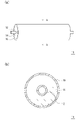
- FIG. 3A is a schematic external view of a charging roll for an electrophotographic apparatus according to an embodiment of the present invention, and is a sectional view taken along line AA thereof (b). It is an enlarged sectional view of the surface layer.
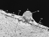
- FIG. 3 is an enlarged cross-sectional photograph of the surface layer of the charged roll of Example 1.
- FIG. 1 is a schematic external view (a) of a charging roll for an electrophotographic apparatus according to an embodiment of the present invention, and a sectional view (b) taken along the line AA.
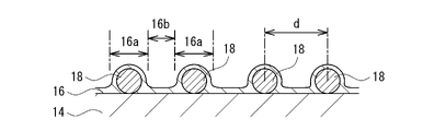
- FIG. 2 is an enlarged cross-sectional view of the surface layer.
- the charged roll 10 includes a shaft body 12, an elastic body layer 14 formed on the outer peripheral surface of the shaft body 12, and a surface layer 16 formed on the outer peripheral surface of the elastic body layer 14.
- the elastic layer 14 is a layer (base layer) that is a base of the charging roll 10.
- the surface layer 16 is a layer that appears on the surface of the charging roll 10.
- an intermediate layer such as a resistance adjusting layer may be formed between the elastic layer 14 and the surface layer 16, if necessary.
- the shaft body 12 is not particularly limited as long as it has conductivity. Specifically, a metal medium substance such as iron, stainless steel, and aluminum, a core metal made of a hollow body, and the like can be exemplified. If necessary, an adhesive, a primer, or the like may be applied to the surface of the shaft body 12. That is, the elastic body layer 14 may be adhered to the shaft body 12 via the adhesive layer (primer layer). The adhesive, primer, etc. may be made conductive as needed.
- the elastic layer 14 contains a crosslinked rubber.
- the elastic layer 14 is formed of a conductive rubber composition containing uncrosslinked rubber.
- the crosslinked rubber is obtained by crosslinking the uncrosslinked rubber.
- the uncrosslinked rubber may be polar rubber or non-polar rubber.
- the polar rubber is a rubber having a polar group, and examples of the polar group include a chloro group, a nitrile group, a carboxyl group, and an epoxy group.
- Specific examples of the polar rubber include hydrin rubber, nitrile rubber (NBR), urethane rubber (U), acrylic rubber (polymer of acrylic acid ester and 2-chloroethyl vinyl ether, ACM), and chloroprene rubber (CR). , Eoxidized natural rubber (ENR) and the like.
- polar rubbers hydrin rubber and nitrile rubber (NBR) are more preferable from the viewpoint that the volume resistivity tends to be particularly low.
- hydrin rubber examples include epichlorohydrin homopolymer (CO), epichlorohydrin-ethylene oxide binary copolymer (ECO), epichlorohydrin-allyl glycidyl ether binary copolymer (GCO), and epichlorohydrin-ethylene oxide-allyl glycidyl ether ternary.
- a copolymer (GECO) and the like can be mentioned.
- the urethane rubber examples include a polyether type urethane rubber having an ether bond in the molecule.
- the polyether type urethane rubber can be produced by reacting a polyether having a hydroxyl group at both ends with a diisocyanate.
- the polyether is not particularly limited, and examples thereof include polyethylene glycol and polypropylene glycol.
- the diisocyanate is not particularly limited, and examples thereof include tolylene diisocyanate and diphenylmethane diisocyanate.
- non-polar rubber examples include silicone rubber (Q), isoprene rubber (IR), natural rubber (NR), styrene-butadiene rubber (SBR), and butadiene rubber (BR).
- silicone rubber is more preferable from the viewpoint of low hardness and resistance to settling (excellent in elastic recovery).
- cross-linking agent examples include a sulfur cross-linking agent, a peroxide cross-linking agent, and a dechlorination cross-linking agent. These cross-linking agents may be used alone or in combination of two or more.
- sulfur cross-linking agent examples include conventionally known sulfur cross-linking agents such as powdered sulfur, precipitated sulfur, colloidal sulfur, surface-treated sulfur, insoluble sulfur, sulfur chloride, thiuram-based vulcanization accelerator, and high molecular weight polysulfide. can.
- peroxide cross-linking agent examples include conventionally known peroxide cross-linking agents such as peroxyketal, dialkyl peroxide, peroxyester, ketone peroxide, peroxydicarbonate, diacyl peroxide, and hydroperoxide. Can be done.
- Examples of the dechlorination cross-linking agent include dithiocarbonate compounds. More specifically, quinoxaline-2,3-dithiocarbonate, 6-methylquinoxaline-2,3-dithiocarbonate, 6-isopropylquinoxaline-2,3-dithiocarbonate, 5,8-dimethylquinoxaline-2,3- Dithiocarbonate and the like can be mentioned.
- the amount of the cross-linking agent to be blended is preferably in the range of 0.1 to 2 parts by mass, more preferably 0.3 to 1.8 parts by mass with respect to 100 parts by mass of the uncrosslinked rubber from the viewpoint of being difficult to bleed. It is within the range of parts, more preferably within the range of 0.5 to 1.5 parts by mass.
- a dechlorination cross-linking accelerator may be used in combination.
- the dechlorination cross-linking accelerator include 1,8-diazabicyclo (5,4,0) undecene-7 (hereinafter abbreviated as DBU) or a weakened salt thereof.
- DBU 1,8-diazabicyclo (5,4,0) undecene-7
- the dechlorination cross-linking accelerator may be used in the form of DBU, but is preferably used in the form of its weak acid salt from the viewpoint of its handling.
- Weak acid salts of DBU include carbonate, stearate, 2-ethylhexylate, benzoate, salicylate, 3-hydroxy-2-naphthoate, phenolic resin salt, 2-mercaptobenzothiazole salt, 2- Examples thereof include mercaptobenzimidazole salt.
- the content of the dechlorination crosslinking accelerator is preferably in the range of 0.1 to 2 parts by mass with respect to 100 parts by mass of the uncrosslinked rubber from the viewpoint of being difficult to bleed. It is more preferably in the range of 0.3 to 1.8 parts by mass, and further preferably in the range of 0.5 to 1.5 parts by mass.
- a conductive agent can be added to the elastic layer 14 to impart conductivity.
- the conductive agent include an electron conductive agent and an ionic conductive agent.
- the electronic conductive agent include carbon black, graphite, and a conductive metal oxide.
- the conductive metal oxide include conductive titanium oxide, conductive zinc oxide, and conductive tin oxide.
- the ionic conductive agent include a quaternary ammonium salt, a borate, and a surfactant. Further, various additives may be appropriately added to the elastic body layer 14, if necessary.
- Additives include lubricants, vulcanization accelerators, anti-aging agents, light stabilizers, viscosity modifiers, processing aids, flame retardants, plasticizers, foaming agents, fillers, dispersants, defoamers, pigments, and release agents. Molds and the like can be mentioned.
- the elastic body layer 14 can be adjusted to a predetermined volume resistivity by the type of crosslinked rubber, the blending amount of the ionic conductive agent, the blending of the electronic conductive agent, and the like.
- the volume resistivity of the elastic layer 14 may be appropriately set in the range of 10 2 to 10 10 ⁇ ⁇ cm, 10 3 to 10 9 ⁇ ⁇ cm, 10 4 to 10 8 ⁇ ⁇ cm, etc., depending on the intended use. ..
- the thickness of the elastic body layer 14 is not particularly limited, and may be appropriately set within the range of 0.1 to 10 mm depending on the intended use.
- the surface layer 16 contains a binder polymer, roughness-forming particles 18, and a surface modifier.
- the binder polymer is a base polymer constituting the surface layer 16.
- Binder polymers include urethane resin, polyamide resin, acrylic resin, acrylic silicone resin, butyral resin (PVB), alkyd resin, polyester resin, fluororubber, fluororesin, mixture of fluororubber and fluororesin, silicone resin, silicone graft acrylic. Examples thereof include polymers, acrylic graft silicone polymers, nitrile rubbers, and urethane rubbers.
- a polymer having a carbonyl group is preferable. This is because the polymer having a carbonyl group is a material having a relatively high dielectric constant, and the charging roll 10 can easily secure excellent chargeability.
- the polymer having a carbonyl group include urethane resin, polyamide resin, acrylic resin, acrylic silicone resin, silicone graft acrylic polymer, acrylic graft silicone polymer, and urethane rubber.
- a polyamide resin, an acrylic resin, an acrylic silicone resin, a silicone graft acrylic polymer, and an acrylic graft silicone polymer are particularly preferable from the viewpoint of excellent wear resistance and the like.
- the polyamide resin may be modified. Examples of the modified polyamide include an alkoxylated polyamide such as N-methoxymethylated nylon.
- the roughness forming particles 18 are particles for imparting roughness to the surface of the surface layer 16. That is, it is a particle for imparting unevenness to the surface of the surface layer 16.
- the portion of the surface layer 16 in which the roughness-forming particles 18 are present is 16a, and the portion of the surface layer 16 in which the roughness-forming particles 18 are not present is 16b.
- the portion 16a in which the roughness-forming particles 18 of the surface layer 16 are present protrudes radially outward from the portion 16b in which the roughness-forming particles 18 of the surface layer 16 are not present.
- the surface unevenness of the surface layer 16 increases the discharge space between the photoconductor and the charging roll 10 and promotes discharge. As a result, the chargeability can be improved and image defects such as horizontal streaks and unevenness can be suppressed.
- Resin particles or the like are used as the roughness forming particles 18.
- the material of the roughness forming particles 18 is not particularly limited.
- the roughness-forming particles 18 are preferably composed of a polymer having a carbonyl group. This is because the polymer having a carbonyl group is a material having a relatively high dielectric constant, and the charging roll 10 can easily secure excellent chargeability.
- the polymer having a carbonyl group include urethane resin, polyamide resin, acrylic resin, acrylic silicone resin, silicone graft acrylic polymer, acrylic graft silicone polymer, and urethane rubber.
- a polyamide resin, an acrylic resin, an acrylic silicone resin, a silicone graft acrylic polymer, and an acrylic graft silicone polymer are particularly preferable from the viewpoint of excellent wear resistance and the like.
- the size of the roughness-forming particles 18 is not particularly limited, but is preferably an average particle diameter of 3.0 ⁇ m or more and 50 ⁇ m or less from the viewpoint of easily ensuring uniform chargeability. More preferably, the average particle size is 5.0 ⁇ m or more and 30 ⁇ m or less.
- the average particle size of the roughness-forming particles 18 is expressed by observing the surface of the surface layer 16 with a laser microscope and using the diameter of the roughness-forming particles 16 visible at the time of surface observation as the particle size, and averaging 20 points.
- the content of the roughness-forming particles 18 in the surface layer 16 is not particularly limited, but is 3 parts by mass with respect to 100 parts by mass of the binder polymer of the surface layer 16 from the viewpoint of easily ensuring uniform chargeability. It is preferably 50 parts by mass or less. More preferably, it is 5 parts by mass or more and 30 parts by mass or less.
- the surface modifier is a fluorine-based or silicone-based nonionic modifier.
- Nonionic surface modifiers do not have anionic or cationic groups.
- Nonionic surface modifiers do not include anionic surface modifiers, cationic surface modifiers, or amphoteric surface modifiers.
- the nonionic surface modifier has a nonionic group, and the nonionic group may be composed of an oligomer or a polymer. That is, the nonionic group may be composed of a polymer in which a plurality of monomers are bonded.
- the oligomer is generally a polymer in which 100 or less monomers are bonded, and the polymer is generally a polymer in which 100 or more monomers are bonded.
- the nonionic group is preferably a hydrocarbon group.
- the number of carbon atoms of the nonionic hydrocarbon group is preferably 2 to 21. More preferably, it is 2 to 8.
- Fluorine-based or silicone-based nonionic modifiers include nonionic fluorosurfactants, nonionic silicone oils, fluorine-modified nonionic acrylic polymers, and silicone-modified nonionic acrylic polymers. , Fluorine-modified nonionic acrylic oligomers, silicone-modified nonionic acrylic oligomers and the like.
- the nonionic group has a high affinity with the binder polymer, and the fluorine-containing group or the silicone group has a low affinity with the binder polymer. Therefore, the fluorine-based or silicone-based nonionic group is arranged near the roughness-forming particles 18 and the nonionic group is arranged far from the roughness-forming particles 18.
- the modifier is oriented.
- the fluorine-based or silicone-based nonionic modifier surrounds the roughness-forming particles 18 and is unevenly distributed around the roughness-forming particles 18 to make the roughness-forming particles 18 independent. It is possible to suppress the aggregation of the roughness-forming particles 18 and improve the dispersibility of the roughness-forming particles 18. Therefore, it is preferable that the surface modifier is unevenly distributed around the roughness forming particles 18 in this way.
- the fluorine-based or silicone-based nonionic modifier can be unevenly distributed near the surface of the surface layer 16 by having a fluorine-containing group or a silicone group. This makes it possible to suppress the adhesion of dirty substances on the roll surface.
- the fluorine-based or silicone-based nonionic modifier is unevenly distributed around the roughness-forming particles 18, the surface of the surface layer 16 on the surface of the portion 16a where the roughness-forming particles 18 are present.
- the amount of the surface modifier is larger than the amount of the surface modifier on the surface of the portion 16b where the roughness forming particles 18 of the surface layer 16 are not present.
- the surface layer 16 contains a fluorine-based or silicone-based nonionic modifier
- aggregation of the roughness-forming particles 18 is suppressed in the binder polymer.
- the dispersibility of the roughness-forming particles 18 on the surface layer 16 is improved, unevenness in the chargeability of the roll surface is suppressed, and unevenness in the image is suppressed.
- the fluorine-based or silicone-based nonionic modifier adheres to contaminants by using a binder polymer having a relatively high dielectric constant as compared with the non-nonionic fluorine-based or silicone-based surface modifier. The effect of suppressing is also high. Dirt substances include toner, toner external additives, and paper dust.
- a fluorine-based nonionic modifier is particularly preferable.
- Fluorine-based nonionic modifiers include nonionic fluorine-based surfactants, fluorine-modified nonionic acrylic polymers, fluorine-modified nonionic acrylic oligomers, and fluorine-modified nonionic urethane. Examples include system oligomers. Since the fluorine-based nonionic modifier has a fluorine-containing group, it tends to be unevenly distributed around the roughness-forming particles 16 and on the surface of the surface layer 16, and the antifouling property of the roll surface and the roughness-forming particles 18 It is superior in the effect of suppressing aggregation. In addition, the tackiness of the surface layer 16 can be suppressed, and the adhesion of dirty substances can be suppressed.
- the surface layer 16 may contain other surface modifiers other than the fluorine-based or silicone-based nonionic modifiers (specific surface modifiers), and may or may not contain other surface modifiers. You may. It is more preferable that the surface layer 16 does not contain other surface modifiers. When the surface layer 16 contains both a specific surface modifier and another surface modifier, the interaction between the specific surface modifier and the other surface modifier causes roughness formation by the specific surface modifier. This is because the effect of suppressing the aggregation of the particles 18 may be reduced. Further, the surface layer 16 may contain only one kind of a specific surface modifier, or may contain two or more kinds. It is more preferable that the surface layer 16 contains only one specific surface modifier.
- the roughness-forming particles 18 have improved dispersibility in the surface layer 16 due to the surface modifier.
- the average value of the inter-particle distances of the roughness-forming particles 18 on the surface layer 16 is 10 ⁇ m or more and 50 ⁇ m or less, and the inter-particle distance of the roughness-forming particles 18 on the surface layer 16.
- the deviation value ⁇ of is preferably 30 or less. More preferably, the average value of the inter-particle distance is 15 ⁇ m or more, 20 or more, 40 ⁇ m or less, 30 ⁇ m or less, and the deviation value ⁇ of the inter-particle distance is 20 or less, 15 or less.
- the interparticle distance of the roughness forming particles 18 on the surface layer 16 is determined by photographing the surface of the surface layer 16 with a laser microscope, drawing an arbitrary straight line on the photographed image, and between the particles on the straight line. Let the distance between the centers be d. The average value and the deviation value ⁇ of the inter-particle distance are calculated from 100 points of the inter-center distance between the particles on the straight line.
- a conductive agent can be added to the surface layer 16 to impart conductivity.
- the conductive agent include an electron conductive agent and an ionic conductive agent.
- the electronic conductive agent include carbon black, graphite, and a conductive metal oxide.
- the conductive metal oxide include conductive titanium oxide, conductive zinc oxide, and conductive tin oxide.
- the ionic conductive agent include a quaternary ammonium salt, a borate, and a surfactant.
- various additives may be appropriately added to the surface layer 16 as needed. Examples of the additive include a plasticizer, a leveling agent, a filler, a vulcanization accelerator, a processing aid, a mold release agent and the like.
- the volume resistivity of the surface layer 16 may be set in the semi-conductive region from the viewpoint of chargeability and the like. Specifically, for example, it may be set within the range of 1.0 ⁇ 10 7 to 1.0 ⁇ 10 10 ⁇ ⁇ cm.
- the volume resistivity can be measured according to JIS K6911.
- the thickness of the surface layer 16 is not particularly limited, and may be set in the range of 0.1 to 3.0 ⁇ m or the like.
- the thickness of the surface layer 16 can be measured by observing the cross section using a laser microscope (for example, "VK-9510" manufactured by KEYENCE). For example, the distances from the surface of the elastic body layer 14 to the surface of the surface layer 16 can be measured at five locations at arbitrary positions and expressed by the average thereof.
- the elastic body layer 14 can be formed, for example, as follows. First, the shaft body 12 is coaxially installed in the hollow portion of the roll molding die, an uncrosslinked conductive rubber composition is injected, heated and cured (crosslinked), and then demolded or demolded. An elastic body layer 14 is formed on the outer periphery of the shaft body 12 by extrusion-molding an uncrosslinked conductive rubber composition on the surface of the shaft body 12.
- the surface layer 16 can be formed by using the forming material of the surface layer 16, applying it to the outer peripheral surface of the elastic body layer 14, and appropriately performing a drying treatment or the like.
- the material for forming the surface layer 16 may contain a diluting solvent.
- the diluting solvent include ketone solvents such as methyl ethyl ketone (MEK) and methyl isobutyl ketone, alcohol solvents such as isopropyl alcohol (IPA), methanol and ethanol, hydrocarbon solvents such as hexane and toluene, ethyl acetate and butyl acetate and the like.
- acetic acid-based solvents diethyl ethers, ether-based solvents such as tetrahydrofuran, and water.
- the surface modifier contained in the surface layer 16 is a fluorine-based or silicone-based nonionic modifier
- the roughness-forming particles 18 are aggregated in the binder polymer. It is suppressed, the dispersibility of the roughness forming particles 18 on the surface layer 16 is improved, the unevenness of the chargeability on the roll surface is suppressed, and the unevenness of the image is suppressed.
- the fluorine-based or silicone-based nonionic modifier adheres to contaminants by using a binder polymer having a relatively high dielectric constant as compared with the non-nonionic fluorine-based or silicone-based surface modifier. The effect of suppressing is also high. Therefore, unevenness of the image due to the surface layer material can be suppressed.
- a core metal (diameter 8 mm) is set in a molding die (pipe shape), the above composition is injected, heated at 180 ° C. for 30 minutes, cooled and demolded, and a thickness of 1 is applied to the outer periphery of the core metal.
- An elastic layer made of a 9.9 mm conductive rubber elastic was formed.
- Example 7 ⁇ Preparation of conductive rubber composition> 30 parts by mass of carbon black, 6 parts by mass of zinc oxide, 2 parts by mass of stearic acid, 1 part by mass of sulfur, 0.5 part by mass of thiazole-based vulcanization accelerator, 0 parts by mass of tyraum-based vulcanization accelerator with respect to 100 parts by mass of isoprene rubber.
- a conductive rubber composition was prepared by blending 5 parts by mass and 50 parts by mass of heavy calcium carbonate and kneading for 10 minutes using a closed mixer whose temperature was adjusted to 50 ° C.
- -Thiazole-based vulcanization accelerator "Noxeller DM” manufactured by Ouchi Shinko Kagaku Kogyo ⁇
- Thiram-based vulcanization accelerator "Noxeller TRA” manufactured by Ouchi Shinko Kagaku Kogyo -Heavy calcium carbonate: "Whiten B” made of Shiraishi calcium, average particle size 3.6 ⁇ m
- -Binder polymer "Fine Resin FR-101" made by Lead City -Binder polymer (acrylic): DIC "Acrydic A-1300" -Roughness forming particles (PA): Arkema "Organsol 2001 UDANT1" average particle diameter 5 ⁇ m -Roughness forming particles (acrylic): Nippon Shokubai's "Epostal MA1006" average particle size 6 ⁇ m -Surface modifier ⁇ 1>: Fluorine-based nonionic modifier, "Surflon S-647” manufactured by AGC Seichemical -Surface modifier ⁇ 2>: Silicone-based nonionic modifier, Shinetsu Silicone "KF-6048” -Surface modifier ⁇ 3>: Fluorine-based anionic modifier, DIC “Megaface F-410" -Surface modifier ⁇ 4>: Fluorine-based cationic modifier, Neos "Futer
- the interparticle distance of the roughness forming particles on the surface layer was measured, and the average value and deviation value ⁇ of the interparticle distance were calculated.
- the distribution state of the surface modifier on the surface layer was analyzed. Further, image evaluation was performed.
- the surface of the surface layer 16 is photographed with a laser microscope, an arbitrary straight line is drawn on the photographed image, and the distance between the particles on the straight line and the center between the particles. It was a distance.
- the average value and the deviation value ⁇ of the inter-particle distance were calculated from 100 points of the inter-center distance between the particles on the straight line.
- the distribution state of the surface modifier on the surface layer was determined by elemental analysis of the surface layer cross section.
- the measurement position is as shown in the enlarged cross-sectional photograph of FIG.
- FIG. 3 is an enlarged cross-sectional photograph of the surface layer 16 of the charged roll of Example 1.
- the measurement position A indicated by the white frame is the surface of the surface layer 16 (position 1.5 ⁇ m in depth from the surface) on the roughness forming particles 18, and the measurement position B indicated by the black frame is the presence of the roughness forming particles 18.
- the surface of the surface layer 16 (position at a depth of 1.0 ⁇ m from the surface) of the unfinished portion, and the measurement position C indicated by the black frame is the inside of the surface layer 16 below the roughness forming particles 18 (above the surface of the elastic body layer 14).
- the measurement position D shown by the black frame is inside the surface layer 16 of the portion where the roughness forming particles 18 do not exist (position 1.5 ⁇ m above the surface of the elastic body layer 14). Is.
- Measuring device ULVAC-PHI X-ray photoelectron spectroscopy analyzer (XPS) "PHI5000 VersaProbe II" X-ray: Al monochrome (200 ⁇ m ⁇ ) Energy: 50W, 15kV Photoelectron extraction angle: 45 °
- the surface modifier is a fluorine-based anionic modifier.
- the surface modifier is a fluorine-based cationic modifier.
- the surface modifier is a fluorine-based amphoteric modifier.
- the surface modifier is a fluorine-based nonionic modifier.
- the surface modifier is a silicone-based nonionic modifier. From the average value of the inter-particle distance and the value of the deviation value ⁇ , in Comparative Examples 1 to 3, the dispersibility of the roughness-forming particles was poor, whereas in Examples 1 and 3 to 7, the roughness-forming particles were found. It can be seen that the dispersibility is good.
- the surface modifier is a fluorine-based nonionic modifier
- the aggregation of the roughness-forming particles in the binder polymer is suppressed, and the dispersibility of the roughness-forming particles in the surface layer is improved. It can be seen that the unevenness of the chargeability on the roll surface is suppressed and the unevenness of the image is suppressed.
- the surface modifier is the same as in Examples 1 and 3 to 7 even in the case of the silicone-based nonionic modifier. Then, from Examples 1 and 2, it can be seen that the fluorine-based nonionic modifier is more likely to be unevenly distributed on the surface than the silicone-based nonionic modifier.
Landscapes
- Physics & Mathematics (AREA)
- Engineering & Computer Science (AREA)
- Plasma & Fusion (AREA)
- General Physics & Mathematics (AREA)
- Electrostatic Charge, Transfer And Separation In Electrography (AREA)
- Rolls And Other Rotary Bodies (AREA)
Abstract
表層材料による画像のムラが抑えられる電子写真機器用帯電ロールを提供する。 軸体12と、軸体12の外周面上に形成された弾性体層14と、弾性体層14の外周面上に形成された表層16と、を備え、表層16が、バインダーポリマーと、粗さ形成用粒子と、表面改質剤と、を含み、表面改質剤が、フッ素系またはシリコーン系のノニオン性改質剤である、電子写真機器用帯電ロール10とする。表面改質剤は、フッ素系のノニオン性改質剤がより好ましい。
Description
本発明は、電子写真方式を採用する複写機、プリンター、ファクシミリなどの電子写真機器において好適に用いられる電子写真機器用帯電ロールに関するものである。
電子写真機器の帯電ロールとしては、芯金などの軸体の外周面上にゴム弾性を有する弾性体層を有し、その弾性体層の外周面上に表層を有するものが知られている。また、帯電ロールでは、例えば荷電特性などから、表層のバインダーポリマーに粗さ形成用粒子を添加することがある。
表層のバインダーポリマーには、帯電性を確保するために、誘電率の高い材料が用いられる。このため、ロール表面の表面エネルギーが高くなり、トナーや紙粉などの汚れ物質が静電的にロール表面に付着し、ロール表面が汚れることで帯電性が変化し、耐久後の画像にムラが出やすくなる。また、表層のバインダーポリマーが誘電率の高い材料であると、バインダーポリマーと粗さ形成用粒子の界面エネルギーの差が大きくなり、表層形成前の材料中において粗さ形成用粒子が互いに吸着しあって凝集する。これにより、表層の粗さ形成用粒子の分散性が悪くなり、ロール表面の帯電性にムラが出て、画像にムラが出やすくなる。
本発明が解決しようとする課題は、表層材料による画像のムラが抑えられる電子写真機器用帯電ロールを提供することにある。
本発明に係る電子写真機器用帯電ロールは、軸体と、前記軸体の外周面上に形成された弾性体層と、前記弾性体層の外周面上に形成された表層と、を備え、前記表層が、バインダーポリマーと、粗さ形成用粒子と、表面改質剤と、を含み、前記表面改質剤が、フッ素系またはシリコーン系のノニオン性改質剤である。
前記粗さ形成用粒子は、カルボニル基を有するポリマーで構成されるとよい。前記バインダーポリマーは、カルボニル基を有するポリマーで構成されるとよい。前記表面改質剤は、前記粗さ形成用粒子の周りに偏在しているとよい。前記表層の前記粗さ形成用粒子が存在している部分の表面における前記表面改質剤の量は、前記表層の前記粗さ形成用粒子が存在していない部分の表面における前記表面改質剤の量よりも多くなっているとよい。前記表面改質剤は、フッ素系のノニオン性改質剤であるとよい。前記表層における前記粗さ形成用粒子の粒子間距離の平均値は10μm以上50μm以下であり、前記表層における前記粗さ形成用粒子の粒子間距離の偏差値σは30以下であるとよい。
本発明に係る電子写真機器用帯電ロールによれば、表層が、バインダーポリマーと、粗さ形成用粒子と、表面改質剤と、を含み、表面改質剤が、フッ素系またはシリコーン系のノニオン性改質剤であることから、表層材料による画像のムラが抑えられる。
前記粗さ形成用粒子がカルボニル基を有するポリマーで構成されると、誘電率の高い材料で前記粗さ形成用粒子が構成されるため、ロール表面の帯電性が向上する。
前記バインダーポリマーがカルボニル基を有するポリマーで構成されると、誘電率の高い材料で前記バインダーポリマーが構成されるため、ロール表面の帯電性が向上する。
前記表面改質剤が前記粗さ形成用粒子の周りに偏在していると、前記粗さ形成用粒子の凝集が抑えられる。これにより、表層の粗さ形成用粒子の分散性がよくなり、ロール表面の帯電性のムラが抑えられ、画像のムラが抑えられる。
前記表層の前記粗さ形成用粒子が存在している部分の表面における前記表面改質剤の量が、前記表層の前記粗さ形成用粒子が存在していない部分の表面における前記表面改質剤の量よりも多くなっていると、前記粗さ形成用粒子の凝集が抑えられる。これにより、表層の粗さ形成用粒子の分散性がよくなり、ロール表面の帯電性のムラが抑えられ、画像のムラが抑えられる。
前記表面改質剤がフッ素系のノニオン性改質剤であると、ロール表面の防汚性および粗さ形成用粒子の凝集抑制効果により優れる。
前記表層における前記粗さ形成用粒子の粒子間距離の平均値が10μm以上50μm以下であり、前記表層における前記粗さ形成用粒子の粒子間距離の偏差値σが30以下であると、粗さ形成用粒子の分散性に優れる。これにより、ロール表面の帯電性のムラが抑えられ、画像のムラが抑えられる。
本発明に係る電子写真機器用帯電ロール(以下、単に帯電ロールということがある。)について詳細に説明する。図1は、本発明の一実施形態に係る電子写真機器用帯電ロールの外観模式図(a)と、そのA-A線断面図(b)である。図2は、表層の拡大断面図である。
帯電ロール10は、軸体12と、軸体12の外周面上に形成された弾性体層14と、弾性体層14の外周面上に形成された表層16と、を備える。弾性体層14は、帯電ロール10のベースとなる層(基層)である。表層16は帯電ロール10の表面に現れる層となっている。なお、特に図示しないが、必要に応じて、抵抗調整層等の中間層が、弾性体層14と表層16の間に形成されていてもよい。
軸体12は、導電性を有するものであれば特に限定されない。具体的には、鉄、ステンレス、アルミニウムなどの金属製の中実体、中空体からなる芯金などを例示することができる。軸体12の表面には、必要に応じて、接着剤、プライマーなどを塗布しても良い。つまり、弾性体層14は、接着剤層(プライマー層)を介して軸体12に接着されていてもよい。接着剤、プライマーなどには、必要に応じて導電化を行っても良い。
弾性体層14は、架橋ゴムを含有する。弾性体層14は、未架橋ゴムを含有する導電性ゴム組成物により形成される。架橋ゴムは、未架橋ゴムを架橋することにより得られる。未架橋ゴムは、極性ゴムであってもよいし、非極性ゴムであってもよい。
極性ゴムは、極性基を有するゴムであり、極性基としては、クロロ基、ニトリル基、カルボキシル基、エポキシ基などを挙げることができる。極性ゴムとしては、具体的には、ヒドリンゴム、ニトリルゴム(NBR)、ウレタンゴム(U)、アクリルゴム(アクリル酸エステルと2-クロロエチルビニルエーテルとの共重合体、ACM)、クロロプレンゴム(CR)、エポキシ化天然ゴム(ENR)などを挙げることができる。極性ゴムのうちでは、体積抵抗率が特に低くなりやすいなどの観点から、ヒドリンゴム、ニトリルゴム(NBR)がより好ましい。
ヒドリンゴムとしては、エピクロルヒドリンの単独重合体(CO)、エピクロルヒドリン-エチレンオキサイド二元共重合体(ECO)、エピクロルヒドリン-アリルグリシジルエーテル二元共重合体(GCO)、エピクロルヒドリン-エチレンオキサイド-アリルグリシジルエーテル三元共重合体(GECO)などを挙げることができる。
ウレタンゴムとしては、分子内にエーテル結合を有するポリエーテル型のウレタンゴムを挙げることができる。ポリエーテル型のウレタンゴムは、両末端にヒドロキシル基を有するポリエーテルとジイソシアネートとの反応により製造できる。ポリエーテルとしては、特に限定されるものではないが、ポリエチレングリコール、ポリプロピレングリコールなどを挙げることができる。ジイソシアネートとしては、特に限定されるものではないが、トリレンジイソシアネート、ジフェニルメタンジイソシアネートなどを挙げることができる。
非極性ゴムとしては、シリコーンゴム(Q)、イソプレンゴム(IR)、天然ゴム(NR)、スチレンブタジエンゴム(SBR)、ブタジエンゴム(BR)などが挙げられる。非極性ゴムのうちでは、低硬度でへたりにくい(弾性回復性に優れる)などの観点から、シリコーンゴムがより好ましい。
架橋剤としては、硫黄架橋剤、過酸化物架橋剤、脱塩素架橋剤を挙げることができる。これらの架橋剤は、単独で用いても良いし、2種以上組み合わせて用いても良い。
硫黄架橋剤としては、粉末硫黄、沈降硫黄、コロイド硫黄、表面処理硫黄、不溶性硫黄、塩化硫黄、チウラム系加硫促進剤、高分子多硫化物などの従来より公知の硫黄架橋剤を挙げることができる。
過酸化物架橋剤としては、パーオキシケタール、ジアルキルパーオキサイド、パーオキシエステル、ケトンパーオキサイド、パーオキシジカーボネート、ジアシルパーオキサイド、ハイドロパーオキサイドなどの従来より公知の過酸化物架橋剤を挙げることができる。
脱塩素架橋剤としては、ジチオカーボネート化合物を挙げることができる。より具体的には、キノキサリン-2,3-ジチオカーボネート、6-メチルキノキサリン-2,3-ジチオカーボネート、6-イソプロピルキノキサリン-2,3-ジチオカーボネート、5,8-ジメチルキノキサリン-2,3-ジチオカーボネートなどを挙げることができる。
架橋剤の配合量としては、ブリードしにくいなどの観点から、未架橋ゴム100質量部に対して、好ましくは0.1~2質量部の範囲内、より好ましくは0.3~1.8質量部の範囲内、さらに好ましくは0.5~1.5質量部の範囲内である。
架橋剤として脱塩素架橋剤を用いる場合には、脱塩素架橋促進剤を併用しても良い。脱塩素架橋促進剤としては、1,8-ジアザビシクロ(5,4,0)ウンデセン-7(以下、DBUと略称する。)もしくはその弱酸塩を挙げることができる。脱塩素架橋促進剤は、DBUの形態として用いても良いが、その取り扱い面から、その弱酸塩の形態として用いることが好ましい。DBUの弱酸塩としては、炭酸塩、ステアリン酸塩、2-エチルヘキシル酸塩、安息香酸塩、サリチル酸塩、3-ヒドロキシ-2-ナフトエ酸塩、フェノール樹脂塩、2-メルカプトベンゾチアゾール塩、2-メルカプトベンズイミダゾール塩などを挙げることができる。
脱塩素架橋促進剤の含有量としては、ブリードしにくいなどの観点から、未架橋ゴム100質量部に対して、0.1~2質量部の範囲内であることが好ましい。より好ましくは0.3~1.8質量部の範囲内、さらに好ましくは0.5~1.5質量部の範囲内である。
弾性体層14には、導電性付与のため、導電剤を配合することができる。導電剤としては、電子導電剤、イオン導電剤が挙げられる。電子導電剤としては、カーボンブラック、グラファイト、導電性金属酸化物が挙げられる。導電性金属酸化物としては、導電性チタン酸化物、導電性亜鉛酸化物、導電性スズ酸化物などが挙げられる。イオン導電剤としては、4級アンモニウム塩、ホウ酸塩、界面活性剤などが挙げられる。また、弾性体層14には、必要に応じて、各種添加剤を適宜添加しても良い。添加剤としては、滑剤、加硫促進剤、老化防止剤、光安定剤、粘度調整剤、加工助剤、難燃剤、可塑剤、発泡剤、充填剤、分散剤、消泡剤、顔料、離型剤などを挙げることができる。
弾性体層14は、架橋ゴムの種類、イオン導電剤の配合量、電子導電剤の配合などにより、所定の体積抵抗率に調整することができる。弾性体層14の体積抵抗率は、用途などに応じて102~1010Ω・cm、103~109Ω・cm、104~108Ω・cmの範囲などに適宜設定すればよい。
弾性体層14の厚みは、特に限定されるものではなく、用途などに応じて0.1~10mmの範囲内などで適宜設定すればよい。
表層16は、バインダーポリマーと、粗さ形成用粒子18と、表面改質剤と、を含む。
バインダーポリマーは、表層16を構成するベースポリマーである。バインダーポリマーとしては、ウレタン樹脂、ポリアミド樹脂、アクリル樹脂、アクリルシリコーン樹脂、ブチラール樹脂(PVB)、アルキッド樹脂、ポリエステル樹脂、フッ素ゴム、フッ素樹脂、フッ素ゴムとフッ素樹脂の混合物、シリコーン樹脂、シリコーングラフトアクリルポリマー、アクリルグラフトシリコーンポリマー、ニトリルゴム、ウレタンゴムなどを挙げることができる。
バインダーポリマーとしては、カルボニル基を有するポリマーが好ましい。カルボニル基を有するポリマーは、比較的誘電率の高い材料であり、帯電ロール10が優れた帯電性を確保しやすいからである。カルボニル基を有するポリマーとしては、ウレタン樹脂、ポリアミド樹脂、アクリル樹脂、アクリルシリコーン樹脂、シリコーングラフトアクリルポリマー、アクリルグラフトシリコーンポリマー、ウレタンゴムなどを挙げることができる。これらのうちでは、耐摩耗性に優れるなどの観点から、ポリアミド樹脂、アクリル樹脂、アクリルシリコーン樹脂、シリコーングラフトアクリルポリマー、アクリルグラフトシリコーンポリマーが特に好ましい。ポリアミド樹脂は、変性されたものであってもよい。変性ポリアミドとしては、N-メトキシメチル化ナイロンなどのアルコキシ化ポリアミドなどを挙げることができる。
粗さ形成用粒子18は、表層16の表面に粗さを付与するための粒子である。つまり、表層16の表面に凹凸を付与するための粒子である。表層16の粗さ形成用粒子18が存在している部分は16aであり、表層16の粗さ形成用粒子18が存在していない部分は16bである。表層16の粗さ形成用粒子18が存在している部分16aは、表層16の粗さ形成用粒子18が存在していない部分16bよりも径方向外側に突出している。表層16の表面凹凸は、感光体と帯電ロール10との間における放電空間を増加させ、放電を促す。これにより、帯電性を向上させ、横スジやムラなどの画像不具合を抑えることができる。
粗さ形成用粒子18は、樹脂製粒子などが用いられる。粗さ形成用粒子18の材料は、特に限定されるものではない。粗さ形成用粒子18は、カルボニル基を有するポリマーで構成されることが好ましい。カルボニル基を有するポリマーは、比較的誘電率の高い材料であり、帯電ロール10が優れた帯電性を確保しやすいからである。カルボニル基を有するポリマーとしては、ウレタン樹脂、ポリアミド樹脂、アクリル樹脂、アクリルシリコーン樹脂、シリコーングラフトアクリルポリマー、アクリルグラフトシリコーンポリマー、ウレタンゴムなどを挙げることができる。これらのうちでは、耐摩耗性に優れるなどの観点から、ポリアミド樹脂、アクリル樹脂、アクリルシリコーン樹脂、シリコーングラフトアクリルポリマー、アクリルグラフトシリコーンポリマーが特に好ましい。
粗さ形成用粒子18の大きさは、特に限定されるものではないが、均一な帯電性を確保しやすいなどの観点から、平均粒子径3.0μm以上50μm以下のものが好ましい。より好ましくは、平均粒子径5.0μm以上30μm以下のものが好ましい。粗さ形成用粒子18の平均粒子径は、表層16の表面をレーザー顕微鏡にて観察し、表面観察時に見える粗さ形成用粒子16の直径を粒径とし、任意の20点の平均で表す。
粗さ形成用粒子18の表層16における含有量は、特に限定されるものではないが、均一な帯電性を確保しやすいなどの観点から、表層16のバインダーポリマー100質量部に対し、3質量部以上50質量部以下であることが好ましい。より好ましくは5質量部以上30質量部以下である。
表面改質剤は、フッ素系またはシリコーン系のノニオン性改質剤である。ノニオン性の表面改質剤は、アニオン性やカチオン性の基を有していないものである。ノニオン性の表面改質剤には、アニオン性の表面改質剤、カチオン性の表面改質剤、両性の表面改質剤は含まれない。ノニオン性の表面改質剤は、ノニオン性の基を有するが、ノニオン性の基は、オリゴマーまたはポリマーで構成されるとよい。すなわち、ノニオン性の基は、複数個のモノマーが結合した重合体で構成されるとよい。オリゴマーは一般的に100個以下のモノマーが結合した重合体であり、ポリマーは一般的に100個以上のモノマーが結合した重合体である。また、ノニオン性の基は、炭化水素基であることが好ましい。ノニオン性の炭化水素基の炭素数としては、2~21が好ましい。より好ましくは2~8である。
フッ素系またはシリコーン系のノニオン性改質剤としては、ノニオン性のフッ素系界面活性剤、ノニオン性のシリコーンオイル、フッ素変性されたノニオン性のアクリル系ポリマー、シリコーン変性されたノニオン性のアクリル系ポリマー、フッ素変性されたノニオン性のアクリル系オリゴマー、シリコーン変性されたノニオン性のアクリル系オリゴマーなどが挙げられる。
フッ素系またはシリコーン系のノニオン性改質剤において、ノニオン性の基は、バインダーポリマーとの親和性が高く、フッ素含有基またはシリコーン基は、バインダーポリマーとの親和性が低い。このため、フッ素含有基またはシリコーン基は粗さ形成用粒子18の近くに配置され、ノニオン性の基は粗さ形成用粒子18から遠くに配置されるように、フッ素系またはシリコーン系のノニオン性改質剤は配向する。これにより、フッ素系またはシリコーン系のノニオン性改質剤は、粗さ形成用粒子18の周りを取り囲み、粗さ形成用粒子18の周りに偏在することで、粗さ形成用粒子18を独立させ、粗さ形成用粒子18の凝集を抑えて粗さ形成用粒子18の分散性を向上することができる。したがって、表面改質剤は、このように粗さ形成用粒子18の周りに偏在しているとよい。
また、フッ素系またはシリコーン系のノニオン性改質剤は、フッ素含有基またはシリコーン基を有することで、表層16の表面近くに偏在することができる。これにより、ロール表面において汚れ物質の付着を抑えることができる。この場合、フッ素系またはシリコーン系のノニオン性改質剤は、粗さ形成用粒子18の周りにも偏在することから、表層16の粗さ形成用粒子18が存在している部分16aの表面における表面改質剤の量が、表層16の粗さ形成用粒子18が存在していない部分16bの表面における表面改質剤の量よりも多くなっている。
このように、表層16がフッ素系またはシリコーン系のノニオン性改質剤を含むことで、バインダーポリマー中において粗さ形成用粒子18の凝集が抑えられる。これにより、表層16の粗さ形成用粒子18の分散性がよくなり、ロール表面の帯電性のムラが抑えられ、画像のムラが抑えられる。また、フッ素系またはシリコーン系のノニオン性改質剤は、非ノニオン性のフッ素系またはシリコーン系の表面改質剤と比較して、比較的誘電率の高いバインダーポリマーを用いることによる汚れ物質の付着を抑える効果も高い。汚れ物質とは、トナーやトナー外添剤、紙粉などである。
表面改質剤は、フッ素系のノニオン性改質剤が特に好ましい。フッ素系のノニオン性改質剤としては、ノニオン性のフッ素系界面活性剤、フッ素変性されたノニオン性のアクリル系ポリマー、フッ素変性されたノニオン性のアクリル系オリゴマー、フッ素変性されたノニオン性のウレタン系オリゴマーなどが挙げられる。フッ素系のノニオン性改質剤は、フッ素含有基を有することから、粗さ形成用粒子16の周りや表層16の表面により偏在しやすく、ロール表面の防汚性および粗さ形成用粒子18の凝集抑制効果により優れる。また、表層16のタック性を抑え、汚れ物質の付着を抑えることができる。
表層16は、フッ素系またはシリコーン系のノニオン性改質剤(特定の表面改質剤)以外の他の表面改質剤を含んでいてもよいし、他の表面改質剤を含んでいなくてもよい。表層16は、他の表面改質剤を含んでいないほうがより好ましい。表層16が特定の表面改質剤と他の表面改質剤の両方を含む場合、特定の表面改質剤と他の表面改質剤の相互作用により、特定の表面改質剤による粗さ形成用粒子18の凝集抑制効果等の効果が低下するおそれがあるからである。また、表層16は、特定の表面改質剤の1種のみ含んでいてもよいし、2種以上含んでいてもよい。表層16は、特定の表面改質剤の1種のみ含んでいるほうがより好ましい。種類の異なる特定の表面改質剤どうしの相互作用により、特定の表面改質剤による粗さ形成用粒子18の凝集抑制効果等の効果が低下するのを抑えられるからである。特定の表面改質剤の1種のみとは、フッ素系のノニオン性改質剤のみ、シリコーン系のノニオン性改質剤のみをいう。さらに、フッ素系のノニオン性改質剤のみにおいて、構造の同じフッ素含有基で構成されるフッ素系のノニオン性改質剤のみをいう。また、シリコーン系のノニオン性改質剤のみにおいて、構造の同じシリコーン基で構成されるシリコーン系のノニオン性改質剤のみをいう。
上記するように、粗さ形成用粒子18は、表面改質剤により、表層16において分散性が向上する。粗さ形成用粒子18の分散性の観点から、表層16における粗さ形成用粒子18の粒子間距離の平均値は10μm以上50μm以下であり、表層16における粗さ形成用粒子18の粒子間距離の偏差値σは30以下であるとよい。より好ましくは、粒子間距離の平均値は15μm以上、20以上、40μm以下、30μm以下、粒子間距離の偏差値σは20以下、15以下である。表層16における粗さ形成用粒子18の粒子間距離は、表層16の表面をレーザー顕微鏡にて撮影し、撮影した画像に任意の直線を1本引き、その直線上にある粒子と粒子の間の中心間距離dとする。粒子間距離の平均値および偏差値σは、その直線上にある粒子と粒子の間の中心間距離100点から算出する。
表層16には、導電性付与のため、導電剤を配合することができる。導電剤としては、電子導電剤、イオン導電剤が挙げられる。電子導電剤としては、カーボンブラック、グラファイト、導電性金属酸化物が挙げられる。導電性金属酸化物としては、導電性チタン酸化物、導電性亜鉛酸化物、導電性スズ酸化物などが挙げられる。イオン導電剤としては、4級アンモニウム塩、ホウ酸塩、界面活性剤などが挙げられる。また、表層16には、必要に応じて、各種添加剤を適宜添加しても良い。添加剤としては、可塑剤、レベリング剤、充填剤、加硫促進剤、加工助剤、離型剤などを挙げることができる。
表層16の体積抵抗率は、帯電性などの観点から、半導電領域に設定するとよい。具体的には、例えば、1.0×10⁷~1.0×10¹⁰Ω・cmの範囲内に設定するとよい。体積抵抗率は、JIS K6911に準拠して測定することができる。表層16の厚さは、特に限定されるものではなく、0.1~3.0μmの範囲などに設定するとよい。表層16の厚さは、レーザー顕微鏡(例えばキーエンス製「VK-9510」など)を用いて断面を観察することにより測定することができる。例えば任意の位置の5か所について、弾性体層14の表面から表層16の表面までの距離をそれぞれ測定し、その平均によって表すことができる。
弾性体層14は、例えば、次のようにして形成することができる。まず、軸体12をロール成形金型の中空部に同軸的に設置し、未架橋の導電性ゴム組成物を注入して、加熱・硬化(架橋)させた後、脱型するか、あるいは、軸体12の表面に未架橋の導電性ゴム組成物を押出成形するなどにより、軸体12の外周に弾性体層14を形成する。
表層16は、表層16の形成材料を用い、これを弾性体層14の外周面に塗工し、乾燥処理などを適宜行うことにより形成することができる。表層16の形成材料は、希釈溶媒を含んでもよい。希釈溶媒としては、メチルエチルケトン(MEK),メチルイソブチルケトンなどのケトン系溶媒、イソプロピルアルコール(IPA),メタノール,エタノールなどのアルコール系溶媒、ヘキサン,トルエンなどの炭化水素系溶媒、酢酸エチル,酢酸ブチルなどの酢酸系溶媒、ジエチルエーテル,テトラヒドロフラン等のエーテル系溶媒、水などが挙げられる。
以上の構成の帯電ロール10によれば、表層16に含まれる表面改質剤がフッ素系またはシリコーン系のノニオン性改質剤であることから、バインダーポリマー中において粗さ形成用粒子18の凝集が抑えられ、表層16における粗さ形成用粒子18の分散性がよくなり、ロール表面の帯電性のムラが抑えられ、画像のムラが抑えられる。また、フッ素系またはシリコーン系のノニオン性改質剤は、非ノニオン性のフッ素系またはシリコーン系の表面改質剤と比較して、比較的誘電率の高いバインダーポリマーを用いることによる汚れ物質の付着を抑える効果も高い。このため、表層材料による画像のムラが抑えられる。
以下、実施例および比較例を用いて本発明を詳細に説明する。
(実施例1~6、比較例1~3)
<導電性ゴム組成物の調製>
ヒドリンゴム(ECO、ダイソー製「エピクロマーCG102」)100質量部に対し、加硫助剤(酸化亜鉛、三井金属製「酸化亜鉛2種」)を5質量部、カーボン(ケッチェンブラックインターナショナル製「ケッチェンブラックEC300J」)を10質量部、加硫促進剤(2-メルカプトベンゾチアゾール、大内新興化学工業社製「ノクセラーM-P」)を0.5質量部、硫黄(鶴見化学工業社製、「サルファックスPTC」)を2質量部、充填剤(炭酸カルシウム、白石工業製「白艶華CC」)を50質量部添加し、これらを攪拌機により撹拌、混合して導電性ゴム組成物を調製した。
<導電性ゴム組成物の調製>
ヒドリンゴム(ECO、ダイソー製「エピクロマーCG102」)100質量部に対し、加硫助剤(酸化亜鉛、三井金属製「酸化亜鉛2種」)を5質量部、カーボン(ケッチェンブラックインターナショナル製「ケッチェンブラックEC300J」)を10質量部、加硫促進剤(2-メルカプトベンゾチアゾール、大内新興化学工業社製「ノクセラーM-P」)を0.5質量部、硫黄(鶴見化学工業社製、「サルファックスPTC」)を2質量部、充填剤(炭酸カルシウム、白石工業製「白艶華CC」)を50質量部添加し、これらを攪拌機により撹拌、混合して導電性ゴム組成物を調製した。
<弾性体層の作製>
成形金型(パイプ状)に芯金(直径8mm)をセットし、上記組成物を注入し、180℃で30分加熱した後、冷却、脱型して、芯金の外周に、厚さ1.9mmの導電性ゴム弾性体からなる弾性体層を形成した。
成形金型(パイプ状)に芯金(直径8mm)をセットし、上記組成物を注入し、180℃で30分加熱した後、冷却、脱型して、芯金の外周に、厚さ1.9mmの導電性ゴム弾性体からなる弾性体層を形成した。
<表層の作製>
表に記載の配合組成(質量部)となるように粗さ形成用粒子とバインダーポリマーと、表面改質剤と、を配合し、メチルエチルケトン(MEK)200質量部を加え、所定の攪拌速度で混合攪拌することにより、表層形成用の液状組成物を調製した。次いで、攪拌を続けながら、この液状組成物を弾性体層の外周面にロールコートし、熱処理を施すことにより、弾性体層の外周に厚さ1.0μmの表層を形成した。これにより、実施例1~6の帯電ロールを作製した。
表に記載の配合組成(質量部)となるように粗さ形成用粒子とバインダーポリマーと、表面改質剤と、を配合し、メチルエチルケトン(MEK)200質量部を加え、所定の攪拌速度で混合攪拌することにより、表層形成用の液状組成物を調製した。次いで、攪拌を続けながら、この液状組成物を弾性体層の外周面にロールコートし、熱処理を施すことにより、弾性体層の外周に厚さ1.0μmの表層を形成した。これにより、実施例1~6の帯電ロールを作製した。
(実施例7)
<導電性ゴム組成物の調製>
イソプレンゴム100質量部に対し、カーボンブラック30質量部、酸化亜鉛6質量部、ステアリン酸2質量部、硫黄1質量部、チアゾール系加硫促進剤0.5質量部、チラウム系加硫促進剤0.5質量部、重質炭酸カルシウム50質量部を配合し、50℃ に温度調節した密閉型ミキサーを用いて10分間混練し、導電性ゴム組成物を調製した。
<導電性ゴム組成物の調製>
イソプレンゴム100質量部に対し、カーボンブラック30質量部、酸化亜鉛6質量部、ステアリン酸2質量部、硫黄1質量部、チアゾール系加硫促進剤0.5質量部、チラウム系加硫促進剤0.5質量部、重質炭酸カルシウム50質量部を配合し、50℃ に温度調節した密閉型ミキサーを用いて10分間混練し、導電性ゴム組成物を調製した。
導電性ゴム組成物の材料として、以下の材料を準備した。
・イソプレンゴム(IR):JSR製「JSR IR2200」
・カーボンブラック:キャボットジャパン製「ショウブラックN762」
・酸化亜鉛:堺化学工業製「酸化亜鉛2種」
・ステアリン酸:日本油脂製「ステアリン酸さくら」
・硫黄:鶴見化学工業製「粉末硫黄」
・チアゾール系加硫促進剤:大内新興化学工業製「ノクセラーDM」
・チラウム系加硫促進剤:大内新興化学工業製「ノクセラーTRA」
・重質炭酸カルシウム:白石カルシウム製「ホワイトンB」、平均粒子径3.6μm
・イソプレンゴム(IR):JSR製「JSR IR2200」
・カーボンブラック:キャボットジャパン製「ショウブラックN762」
・酸化亜鉛:堺化学工業製「酸化亜鉛2種」
・ステアリン酸:日本油脂製「ステアリン酸さくら」
・硫黄:鶴見化学工業製「粉末硫黄」
・チアゾール系加硫促進剤:大内新興化学工業製「ノクセラーDM」
・チラウム系加硫促進剤:大内新興化学工業製「ノクセラーTRA」
・重質炭酸カルシウム:白石カルシウム製「ホワイトンB」、平均粒子径3.6μm
<弾性体層の作製>
導電性ゴム組成物を変更した以外は実施例1と同様にして、芯金の外周に、厚さ1.9mmの導電性ゴム弾性体からなる弾性体層を形成した。
導電性ゴム組成物を変更した以外は実施例1と同様にして、芯金の外周に、厚さ1.9mmの導電性ゴム弾性体からなる弾性体層を形成した。
<表層の作製>
実施例1と同様にして、弾性体層の外周に厚さ1.0μmの表層を形成した。これにより、実施例7の帯電ロールを作製した。
実施例1と同様にして、弾性体層の外周に厚さ1.0μmの表層を形成した。これにより、実施例7の帯電ロールを作製した。
表層材料として用いた材料は以下の通りである。
・バインダーポリマー(PA):鉛市製「ファインレジンFR-101」
・バインダーポリマー(アクリル):DIC製「アクリディックA-1300」
・粗さ形成用粒子(PA):アルケマ製「オルガソール2001UDNAT1」平均粒子径5μm
・粗さ形成用粒子(アクリル):日本触媒製「エポスターMA1006」平均粒子径6μm
・表面改質剤<1>:フッ素系のノニオン性改質剤、AGCセイケミカル製「サーフロンS-647」
・表面改質剤<2>:シリコーン系のノニオン性改質剤、信越シリコーン製「KF-6048」
・表面改質剤<3>:フッ素系のアニオン性改質剤、DIC製「メガフェイスF-410」
・表面改質剤<4>:フッ素系のカチオン性改質剤、ネオス製「フタージェント320」
・表面改質剤<5>:フッ素系の両性改質剤、ネオス製「フタージェント400SW」
作製した帯電ロールについて、表層における粗さ形成用粒子の粒子間距離を測定し、粒子間距離の平均値および偏差値σを算出した。また、表層における表面改質剤の分布状態を分析した。さらに、画像評価を行った。
(粒子間距離)
表層における粗さ形成用粒子の粒子間距離は、表層16の表面をレーザー顕微鏡にて撮影し、撮影した画像に任意の直線を1本引き、その直線上にある粒子と粒子の間の中心間距離とした。粒子間距離の平均値および偏差値σは、その直線上にある粒子と粒子の間の中心間距離100点から算出した。
表層における粗さ形成用粒子の粒子間距離は、表層16の表面をレーザー顕微鏡にて撮影し、撮影した画像に任意の直線を1本引き、その直線上にある粒子と粒子の間の中心間距離とした。粒子間距離の平均値および偏差値σは、その直線上にある粒子と粒子の間の中心間距離100点から算出した。
(表面改質剤の分布状態)
表層における表面改質剤の分布状態は、表層断面の元素分析により行った。測定位置は、図3の拡大断面写真に示す通りである。図3は、実施例1の帯電ロールの表層16の拡大断面写真である。白枠で示す測定位置Aは、粗さ形成用粒子18上の表層16表面(表面から深さ1.5μmの位置)であり、黒枠で示す測定位置Bは、粗さ形成用粒子18の存在していない部分の表層16表面(表面から深さ1.0μmの位置)であり、黒枠で示す測定位置Cは、粗さ形成用粒子18下の表層16内部(弾性体層14の表面から上に1.0μmの位置)であり、黒枠で示す測定位置Dは、粗さ形成用粒子18の存在していない部分の表層16内部(弾性体層14の表面から上に1.5μmの位置)である。
<測定条件>
測定装置:アルバック・ファイ製 X線光電子分光分析装置(XPS)「PHI5000 VersaProbeII」
X-ray:Alモノクロ(200μmφ)
エネルギー:50W、15kV
光電子取出し角度:45°
中和銃:E-Neut+IG-Neut
(画像評価)
作製した帯電ロールを実機(RICOH製「MP C6004」)のユニット(ブラック)に取り付け、10℃×10%RH環境下にて25%濃度ハーフトーンにて画出し50万枚耐久後の評価(均一性)を行った。画像にムラがなかったものを良好「〇」、画像にムラが生じたものを不良「×」とした。
作製した帯電ロールを実機(RICOH製「MP C6004」)のユニット(ブラック)に取り付け、10℃×10%RH環境下にて25%濃度ハーフトーンにて画出し50万枚耐久後の評価(均一性)を行った。画像にムラがなかったものを良好「〇」、画像にムラが生じたものを不良「×」とした。

比較例1は、表面改質剤がフッ素系のアニオン性改質剤である。比較例2は、表面改質剤がフッ素系のカチオン性改質剤である。比較例3は、表面改質剤がフッ素系の両性改質剤である。これらに対し、実施例1、3~7は、表面改質剤がフッ素系のノニオン性改質剤である。また、実施例2は、表面改質剤がシリコーン系のノニオン性改質剤である。粒子間距離の平均値および偏差値σの値から、比較例1~3は、粗さ形成用粒子の分散性が悪いのに対し、実施例1、3~7は、粗さ形成用粒子の分散性がよいことがわかる。また、表層断面の元素分析の結果から、比較例1~3は、表面改質剤が粒子上の表面、粒子の無いところの表面、粒子下の内部、粒子の無いところの内部にそれぞれ同じ程度に分布しているのに対し、実施例1、3~7は、表面改質剤が内部よりも表面に偏在しており、さらに、粒子の無いところの表面よりも粒子上の表面に偏在していることがわかる。そして、比較例1~3は、耐久画像にムラが生じているのに対し、実施例1、3~7は、耐久画像にムラが生じていない。以上より、表面改質剤がフッ素系のノニオン性改質剤であることで、バインダーポリマー中において粗さ形成用粒子の凝集が抑えられ、表層における粗さ形成用粒子の分散性がよくなり、ロール表面の帯電性のムラが抑えられ、画像のムラが抑えられることがわかる。また、実施例2から、表面改質剤がシリコーン系のノニオン性改質剤においても、実施例1、3~7と同様であることがわかる。そして、実施例1~2から、シリコーン系のノニオン性改質剤よりもフッ素系のノニオン性改質剤のほうが、表面により偏在しやすいことがわかる。
以上、本発明の実施形態・実施例について説明したが、本発明は上記実施形態・実施例に何ら限定されるものではなく、本発明の趣旨を逸脱しない範囲内で種々の改変が可能である。
10 帯電ロール
12 軸体
14 弾性体層
16 表層
18 粗さ形成用粒子
12 軸体
14 弾性体層
16 表層
18 粗さ形成用粒子
Claims (7)
- 軸体と、前記軸体の外周面上に形成された弾性体層と、前記弾性体層の外周面上に形成された表層と、を備え、
前記表層が、バインダーポリマーと、粗さ形成用粒子と、表面改質剤と、を含み、
前記表面改質剤が、フッ素系またはシリコーン系のノニオン性改質剤である、電子写真機器用帯電ロール。 - 前記粗さ形成用粒子が、カルボニル基を有するポリマーで構成される、請求項1に記載の電子写真機器用帯電ロール。
- 前記バインダーポリマーが、カルボニル基を有するポリマーで構成される、請求項1または請求項2に記載の電子写真機器用帯電ロール。
- 前記表面改質剤が、前記粗さ形成用粒子の周りに偏在している、請求項1から請求項3のいずれか1項に記載の電子写真機器用帯電ロール。
- 前記表層の前記粗さ形成用粒子が存在している部分の表面における前記表面改質剤の量が、前記表層の前記粗さ形成用粒子が存在していない部分の表面における前記表面改質剤の量よりも多くなっている、請求項1から請求項4のいずれか1項に記載の電子写真機器用帯電ロール。
- 前記表面改質剤が、フッ素系のノニオン性改質剤である、請求項1から請求項5のいずれか1項に記載の電子写真機器用帯電ロール。
- 前記表層における前記粗さ形成用粒子の粒子間距離の平均値が10μm以上50μm以下であり、前記表層における前記粗さ形成用粒子の粒子間距離の偏差値σが30以下である、請求項1から請求項6のいずれか1項に記載の電子写真機器用帯電ロール。
Applications Claiming Priority (2)
| Application Number | Priority Date | Filing Date | Title |
|---|---|---|---|
| JP2020214963A JP2022100770A (ja) | 2020-12-24 | 2020-12-24 | 電子写真機器用帯電ロール |
| JP2020-214963 | 2020-12-24 |
Publications (1)
| Publication Number | Publication Date |
|---|---|
| WO2022138202A1 true WO2022138202A1 (ja) | 2022-06-30 |
Family
ID=82157729
Family Applications (1)
| Application Number | Title | Priority Date | Filing Date |
|---|---|---|---|
| PCT/JP2021/045326 WO2022138202A1 (ja) | 2020-12-24 | 2021-12-09 | 電子写真機器用帯電ロール |
Country Status (2)
| Country | Link |
|---|---|
| JP (1) | JP2022100770A (ja) |
| WO (1) | WO2022138202A1 (ja) |
Citations (2)
| Publication number | Priority date | Publication date | Assignee | Title |
|---|---|---|---|---|
| JP2017156396A (ja) * | 2016-02-29 | 2017-09-07 | 住友理工株式会社 | 電子写真機器用帯電ロール |
| JP2018136434A (ja) * | 2017-02-22 | 2018-08-30 | 住友理工株式会社 | 電子写真機器用帯電部材および電子写真機器用帯電部材の製造方法 |
-
2020
- 2020-12-24 JP JP2020214963A patent/JP2022100770A/ja active Pending
-
2021
- 2021-12-09 WO PCT/JP2021/045326 patent/WO2022138202A1/ja active Application Filing
Patent Citations (2)
| Publication number | Priority date | Publication date | Assignee | Title |
|---|---|---|---|---|
| JP2017156396A (ja) * | 2016-02-29 | 2017-09-07 | 住友理工株式会社 | 電子写真機器用帯電ロール |
| JP2018136434A (ja) * | 2017-02-22 | 2018-08-30 | 住友理工株式会社 | 電子写真機器用帯電部材および電子写真機器用帯電部材の製造方法 |
Also Published As
| Publication number | Publication date |
|---|---|
| JP2022100770A (ja) | 2022-07-06 |
Similar Documents
| Publication | Publication Date | Title |
|---|---|---|
| JP6722606B2 (ja) | 電子写真機器用帯電ロール | |
| JP6155416B1 (ja) | 電子写真機器用帯電ロール | |
| WO2016158813A1 (ja) | 電子写真機器用導電性部材 | |
| JP6714529B2 (ja) | 電子写真機器用帯電部材および電子写真機器用帯電部材の製造方法 | |
| US20230314980A1 (en) | Charging roll for electrophotographic apparatus | |
| JP2021096377A (ja) | 電子写真機器用導電性ロール | |
| WO2022138202A1 (ja) | 電子写真機器用帯電ロール | |
| WO2018061441A1 (ja) | 電子写真機器用帯電ロール | |
| JP6722613B2 (ja) | 電子写真機器用帯電ロール | |
| JP6909623B2 (ja) | 電子写真機器用現像ロール | |
| JP2017083711A (ja) | 電子写真機器用帯電ロール | |
| WO2017164317A1 (ja) | 電子写真機器用帯電ロール | |
| JP6850094B2 (ja) | 電子写真機器用導電性ロール | |
| WO2020158550A1 (ja) | 電子写真機器用帯電ロール | |
| JP2017116685A (ja) | 電子写真機器用導電性部材 | |
| WO2023127398A1 (ja) | 電子写真機器用帯電ロールおよび電子写真機器用帯電ロールの製造方法 | |
| WO2023276649A1 (ja) | 電子写真機器用帯電ロールおよび電子写真機器用帯電ロールの製造方法 | |
| JP7079719B2 (ja) | 電子写真機器用導電性部材 | |
| JP2023067019A (ja) | 電子写真機器用帯電ロールおよび電子写真機器用帯電ロールの製造方法 | |
| JP2024018809A (ja) | 電子写真機器用帯電ロール | |
| JP2024025253A (ja) | 電子写真機器用帯電ロール |
Legal Events
| Date | Code | Title | Description |
|---|---|---|---|
| 121 | Ep: the epo has been informed by wipo that ep was designated in this application |
Ref document number: 21910351 Country of ref document: EP Kind code of ref document: A1 |
|
| NENP | Non-entry into the national phase |
Ref country code: DE |
|
| 122 | Ep: pct application non-entry in european phase |
Ref document number: 21910351 Country of ref document: EP Kind code of ref document: A1 |