WO2022131024A1 - 伝動ユニットおよび動力システム - Google Patents
伝動ユニットおよび動力システム Download PDFInfo
- Publication number
- WO2022131024A1 WO2022131024A1 PCT/JP2021/044478 JP2021044478W WO2022131024A1 WO 2022131024 A1 WO2022131024 A1 WO 2022131024A1 JP 2021044478 W JP2021044478 W JP 2021044478W WO 2022131024 A1 WO2022131024 A1 WO 2022131024A1
- Authority
- WO
- WIPO (PCT)
- Prior art keywords
- engine
- output shaft
- drive source
- clutch
- transmission
- Prior art date
- Legal status (The legal status is an assumption and is not a legal conclusion. Google has not performed a legal analysis and makes no representation as to the accuracy of the status listed.)
- Ceased
Links
Images




Classifications
-
- F—MECHANICAL ENGINEERING; LIGHTING; HEATING; WEAPONS; BLASTING
- F02—COMBUSTION ENGINES; HOT-GAS OR COMBUSTION-PRODUCT ENGINE PLANTS
- F02B—INTERNAL-COMBUSTION PISTON ENGINES; COMBUSTION ENGINES IN GENERAL
- F02B63/00—Adaptations of engines for driving pumps, hand-held tools or electric generators; Portable combinations of engines with engine-driven devices
- F02B63/04—Adaptations of engines for driving pumps, hand-held tools or electric generators; Portable combinations of engines with engine-driven devices for electric generators
-
- B—PERFORMING OPERATIONS; TRANSPORTING
- B60—VEHICLES IN GENERAL
- B60K—ARRANGEMENT OR MOUNTING OF PROPULSION UNITS OR OF TRANSMISSIONS IN VEHICLES; ARRANGEMENT OR MOUNTING OF PLURAL DIVERSE PRIME-MOVERS IN VEHICLES; AUXILIARY DRIVES FOR VEHICLES; INSTRUMENTATION OR DASHBOARDS FOR VEHICLES; ARRANGEMENTS IN CONNECTION WITH COOLING, AIR INTAKE, GAS EXHAUST OR FUEL SUPPLY OF PROPULSION UNITS IN VEHICLES
- B60K6/00—Arrangement or mounting of plural diverse prime-movers for mutual or common propulsion, e.g. hybrid propulsion systems comprising electric motors and internal combustion engines
- B60K6/20—Arrangement or mounting of plural diverse prime-movers for mutual or common propulsion, e.g. hybrid propulsion systems comprising electric motors and internal combustion engines the prime-movers consisting of electric motors and internal combustion engines, e.g. HEVs
- B60K6/42—Arrangement or mounting of plural diverse prime-movers for mutual or common propulsion, e.g. hybrid propulsion systems comprising electric motors and internal combustion engines the prime-movers consisting of electric motors and internal combustion engines, e.g. HEVs characterised by the architecture of the hybrid electric vehicle
- B60K6/48—Parallel type
-
- B—PERFORMING OPERATIONS; TRANSPORTING
- B60—VEHICLES IN GENERAL
- B60K—ARRANGEMENT OR MOUNTING OF PROPULSION UNITS OR OF TRANSMISSIONS IN VEHICLES; ARRANGEMENT OR MOUNTING OF PLURAL DIVERSE PRIME-MOVERS IN VEHICLES; AUXILIARY DRIVES FOR VEHICLES; INSTRUMENTATION OR DASHBOARDS FOR VEHICLES; ARRANGEMENTS IN CONNECTION WITH COOLING, AIR INTAKE, GAS EXHAUST OR FUEL SUPPLY OF PROPULSION UNITS IN VEHICLES
- B60K6/00—Arrangement or mounting of plural diverse prime-movers for mutual or common propulsion, e.g. hybrid propulsion systems comprising electric motors and internal combustion engines
- B60K6/20—Arrangement or mounting of plural diverse prime-movers for mutual or common propulsion, e.g. hybrid propulsion systems comprising electric motors and internal combustion engines the prime-movers consisting of electric motors and internal combustion engines, e.g. HEVs
- B60K6/22—Arrangement or mounting of plural diverse prime-movers for mutual or common propulsion, e.g. hybrid propulsion systems comprising electric motors and internal combustion engines the prime-movers consisting of electric motors and internal combustion engines, e.g. HEVs characterised by apparatus, components or means specially adapted for HEVs
- B60K6/36—Arrangement or mounting of plural diverse prime-movers for mutual or common propulsion, e.g. hybrid propulsion systems comprising electric motors and internal combustion engines the prime-movers consisting of electric motors and internal combustion engines, e.g. HEVs characterised by apparatus, components or means specially adapted for HEVs characterised by the transmission gearings
-
- B—PERFORMING OPERATIONS; TRANSPORTING
- B60—VEHICLES IN GENERAL
- B60K—ARRANGEMENT OR MOUNTING OF PROPULSION UNITS OR OF TRANSMISSIONS IN VEHICLES; ARRANGEMENT OR MOUNTING OF PLURAL DIVERSE PRIME-MOVERS IN VEHICLES; AUXILIARY DRIVES FOR VEHICLES; INSTRUMENTATION OR DASHBOARDS FOR VEHICLES; ARRANGEMENTS IN CONNECTION WITH COOLING, AIR INTAKE, GAS EXHAUST OR FUEL SUPPLY OF PROPULSION UNITS IN VEHICLES
- B60K6/00—Arrangement or mounting of plural diverse prime-movers for mutual or common propulsion, e.g. hybrid propulsion systems comprising electric motors and internal combustion engines
- B60K6/20—Arrangement or mounting of plural diverse prime-movers for mutual or common propulsion, e.g. hybrid propulsion systems comprising electric motors and internal combustion engines the prime-movers consisting of electric motors and internal combustion engines, e.g. HEVs
- B60K6/22—Arrangement or mounting of plural diverse prime-movers for mutual or common propulsion, e.g. hybrid propulsion systems comprising electric motors and internal combustion engines the prime-movers consisting of electric motors and internal combustion engines, e.g. HEVs characterised by apparatus, components or means specially adapted for HEVs
- B60K6/38—Arrangement or mounting of plural diverse prime-movers for mutual or common propulsion, e.g. hybrid propulsion systems comprising electric motors and internal combustion engines the prime-movers consisting of electric motors and internal combustion engines, e.g. HEVs characterised by apparatus, components or means specially adapted for HEVs characterised by the driveline clutches
- B60K6/387—Actuated clutches, i.e. clutches engaged or disengaged by electric, hydraulic or mechanical actuating means
-
- B—PERFORMING OPERATIONS; TRANSPORTING
- B60—VEHICLES IN GENERAL
- B60K—ARRANGEMENT OR MOUNTING OF PROPULSION UNITS OR OF TRANSMISSIONS IN VEHICLES; ARRANGEMENT OR MOUNTING OF PLURAL DIVERSE PRIME-MOVERS IN VEHICLES; AUXILIARY DRIVES FOR VEHICLES; INSTRUMENTATION OR DASHBOARDS FOR VEHICLES; ARRANGEMENTS IN CONNECTION WITH COOLING, AIR INTAKE, GAS EXHAUST OR FUEL SUPPLY OF PROPULSION UNITS IN VEHICLES
- B60K6/00—Arrangement or mounting of plural diverse prime-movers for mutual or common propulsion, e.g. hybrid propulsion systems comprising electric motors and internal combustion engines
- B60K6/20—Arrangement or mounting of plural diverse prime-movers for mutual or common propulsion, e.g. hybrid propulsion systems comprising electric motors and internal combustion engines the prime-movers consisting of electric motors and internal combustion engines, e.g. HEVs
- B60K6/22—Arrangement or mounting of plural diverse prime-movers for mutual or common propulsion, e.g. hybrid propulsion systems comprising electric motors and internal combustion engines the prime-movers consisting of electric motors and internal combustion engines, e.g. HEVs characterised by apparatus, components or means specially adapted for HEVs
- B60K6/40—Arrangement or mounting of plural diverse prime-movers for mutual or common propulsion, e.g. hybrid propulsion systems comprising electric motors and internal combustion engines the prime-movers consisting of electric motors and internal combustion engines, e.g. HEVs characterised by apparatus, components or means specially adapted for HEVs characterised by the assembly or relative disposition of components
-
- B—PERFORMING OPERATIONS; TRANSPORTING
- B60—VEHICLES IN GENERAL
- B60K—ARRANGEMENT OR MOUNTING OF PROPULSION UNITS OR OF TRANSMISSIONS IN VEHICLES; ARRANGEMENT OR MOUNTING OF PLURAL DIVERSE PRIME-MOVERS IN VEHICLES; AUXILIARY DRIVES FOR VEHICLES; INSTRUMENTATION OR DASHBOARDS FOR VEHICLES; ARRANGEMENTS IN CONNECTION WITH COOLING, AIR INTAKE, GAS EXHAUST OR FUEL SUPPLY OF PROPULSION UNITS IN VEHICLES
- B60K6/00—Arrangement or mounting of plural diverse prime-movers for mutual or common propulsion, e.g. hybrid propulsion systems comprising electric motors and internal combustion engines
- B60K6/20—Arrangement or mounting of plural diverse prime-movers for mutual or common propulsion, e.g. hybrid propulsion systems comprising electric motors and internal combustion engines the prime-movers consisting of electric motors and internal combustion engines, e.g. HEVs
- B60K6/22—Arrangement or mounting of plural diverse prime-movers for mutual or common propulsion, e.g. hybrid propulsion systems comprising electric motors and internal combustion engines the prime-movers consisting of electric motors and internal combustion engines, e.g. HEVs characterised by apparatus, components or means specially adapted for HEVs
- B60K6/40—Arrangement or mounting of plural diverse prime-movers for mutual or common propulsion, e.g. hybrid propulsion systems comprising electric motors and internal combustion engines the prime-movers consisting of electric motors and internal combustion engines, e.g. HEVs characterised by apparatus, components or means specially adapted for HEVs characterised by the assembly or relative disposition of components
- B60K6/405—Housings
-
- F—MECHANICAL ENGINEERING; LIGHTING; HEATING; WEAPONS; BLASTING
- F16—ENGINEERING ELEMENTS AND UNITS; GENERAL MEASURES FOR PRODUCING AND MAINTAINING EFFECTIVE FUNCTIONING OF MACHINES OR INSTALLATIONS; THERMAL INSULATION IN GENERAL
- F16H—GEARING
- F16H57/00—General details of gearing
- F16H57/02—Gearboxes; Mounting gearing therein
-
- B—PERFORMING OPERATIONS; TRANSPORTING
- B60—VEHICLES IN GENERAL
- B60K—ARRANGEMENT OR MOUNTING OF PROPULSION UNITS OR OF TRANSMISSIONS IN VEHICLES; ARRANGEMENT OR MOUNTING OF PLURAL DIVERSE PRIME-MOVERS IN VEHICLES; AUXILIARY DRIVES FOR VEHICLES; INSTRUMENTATION OR DASHBOARDS FOR VEHICLES; ARRANGEMENTS IN CONNECTION WITH COOLING, AIR INTAKE, GAS EXHAUST OR FUEL SUPPLY OF PROPULSION UNITS IN VEHICLES
- B60K6/00—Arrangement or mounting of plural diverse prime-movers for mutual or common propulsion, e.g. hybrid propulsion systems comprising electric motors and internal combustion engines
- B60K6/20—Arrangement or mounting of plural diverse prime-movers for mutual or common propulsion, e.g. hybrid propulsion systems comprising electric motors and internal combustion engines the prime-movers consisting of electric motors and internal combustion engines, e.g. HEVs
- B60K6/42—Arrangement or mounting of plural diverse prime-movers for mutual or common propulsion, e.g. hybrid propulsion systems comprising electric motors and internal combustion engines the prime-movers consisting of electric motors and internal combustion engines, e.g. HEVs characterised by the architecture of the hybrid electric vehicle
- B60K6/48—Parallel type
- B60K2006/4833—Step up or reduction gearing driving generator, e.g. to operate generator in most efficient speed range
-
- B—PERFORMING OPERATIONS; TRANSPORTING
- B60—VEHICLES IN GENERAL
- B60W—CONJOINT CONTROL OF VEHICLE SUB-UNITS OF DIFFERENT TYPE OR DIFFERENT FUNCTION; CONTROL SYSTEMS SPECIALLY ADAPTED FOR HYBRID VEHICLES; ROAD VEHICLE DRIVE CONTROL SYSTEMS FOR PURPOSES NOT RELATED TO THE CONTROL OF A PARTICULAR SUB-UNIT
- B60W2300/00—Indexing codes relating to the type of vehicle
- B60W2300/12—Trucks; Load vehicles
- B60W2300/121—Fork lift trucks, Clarks
-
- B—PERFORMING OPERATIONS; TRANSPORTING
- B60—VEHICLES IN GENERAL
- B60Y—INDEXING SCHEME RELATING TO ASPECTS CROSS-CUTTING VEHICLE TECHNOLOGY
- B60Y2200/00—Type of vehicle
- B60Y2200/90—Vehicles comprising electric prime movers
- B60Y2200/92—Hybrid vehicles
-
- F—MECHANICAL ENGINEERING; LIGHTING; HEATING; WEAPONS; BLASTING
- F16—ENGINEERING ELEMENTS AND UNITS; GENERAL MEASURES FOR PRODUCING AND MAINTAINING EFFECTIVE FUNCTIONING OF MACHINES OR INSTALLATIONS; THERMAL INSULATION IN GENERAL
- F16H—GEARING
- F16H1/00—Toothed gearings for conveying rotary motion
- F16H1/02—Toothed gearings for conveying rotary motion without gears having orbital motion
- F16H1/20—Toothed gearings for conveying rotary motion without gears having orbital motion involving more than two intermeshing members
-
- F—MECHANICAL ENGINEERING; LIGHTING; HEATING; WEAPONS; BLASTING
- F16—ENGINEERING ELEMENTS AND UNITS; GENERAL MEASURES FOR PRODUCING AND MAINTAINING EFFECTIVE FUNCTIONING OF MACHINES OR INSTALLATIONS; THERMAL INSULATION IN GENERAL
- F16H—GEARING
- F16H57/00—General details of gearing
- F16H57/02—Gearboxes; Mounting gearing therein
- F16H2057/02034—Gearboxes combined or connected with electric machines
-
- F—MECHANICAL ENGINEERING; LIGHTING; HEATING; WEAPONS; BLASTING
- F16—ENGINEERING ELEMENTS AND UNITS; GENERAL MEASURES FOR PRODUCING AND MAINTAINING EFFECTIVE FUNCTIONING OF MACHINES OR INSTALLATIONS; THERMAL INSULATION IN GENERAL
- F16H—GEARING
- F16H57/00—General details of gearing
- F16H57/02—Gearboxes; Mounting gearing therein
- F16H2057/02039—Gearboxes for particular applications
- F16H2057/02043—Gearboxes for particular applications for vehicle transmissions
-
- F—MECHANICAL ENGINEERING; LIGHTING; HEATING; WEAPONS; BLASTING
- F16—ENGINEERING ELEMENTS AND UNITS; GENERAL MEASURES FOR PRODUCING AND MAINTAINING EFFECTIVE FUNCTIONING OF MACHINES OR INSTALLATIONS; THERMAL INSULATION IN GENERAL
- F16H—GEARING
- F16H57/00—General details of gearing
- F16H57/02—Gearboxes; Mounting gearing therein
- F16H57/031—Gearboxes; Mounting gearing therein characterised by covers or lids for gearboxes
-
- Y—GENERAL TAGGING OF NEW TECHNOLOGICAL DEVELOPMENTS; GENERAL TAGGING OF CROSS-SECTIONAL TECHNOLOGIES SPANNING OVER SEVERAL SECTIONS OF THE IPC; TECHNICAL SUBJECTS COVERED BY FORMER USPC CROSS-REFERENCE ART COLLECTIONS [XRACs] AND DIGESTS
- Y02—TECHNOLOGIES OR APPLICATIONS FOR MITIGATION OR ADAPTATION AGAINST CLIMATE CHANGE
- Y02T—CLIMATE CHANGE MITIGATION TECHNOLOGIES RELATED TO TRANSPORTATION
- Y02T10/00—Road transport of goods or passengers
- Y02T10/60—Other road transportation technologies with climate change mitigation effect
- Y02T10/62—Hybrid vehicles
Definitions
- the present invention relates to a transmission unit and a power system.
- This application claims priority based on Japanese Patent Application No. 2020-21069 filed in Japan on December 18, 2020, the contents of which are incorporated herein by reference.
- Patent Documents 1 and 2 provide a hydraulic clutch 14 between an engine 10 and a motor 15 in a drive system of a hybrid vehicle, and control the engagement and disengagement of the clutch 14 to obtain an engine traveling mode and an EV traveling mode.
- a technique for smoothing the switching between the two is disclosed.
- a second drive source such as a motor is retrofitted to a first drive source such as an engine.
- a second drive source can be retrofitted to the existing first drive source and hybridized, a highly versatile power system can be configured.
- the present invention provides a transmission unit and a power system capable of efficiently installing a second drive source in the first drive source and hybridizing the second drive source.
- a connecting element that connects an output shaft of a drive source and an input shaft of a driven device driven by the drive force of the drive source so as to be able to transmit power, and the drive source are Separately, a second drive source for generating a driving force is provided, and the second drive source is a transmission unit arranged so as to avoid the connecting element when viewed from the axial direction of the output shaft.
- the second drive source is a motor generator, which has a second output shaft offset with respect to the output shaft, the output shaft and the said.
- a transmission mechanism capable of increasing the driving force of the output shaft and transmitting it to the second output shaft is provided between the second output shaft and the second output shaft.
- a third aspect of the present invention comprises, in the second aspect, a transmission case capable of transmitting power between the output shaft and the second output shaft and accommodating the transmission mechanism.
- a rotating body housing for accommodating a rotating body that rotates integrally with the output shaft is provided at a portion of the transmission case on the drive source side, and the second drive source is a portion of the transmission case on the drive source side. It is arranged so as to avoid the rotating body housing.
- a fourth aspect of the present invention is that in the third aspect, the transmission case is formed in a flat shape in which the width in the axial direction is narrower than the width in the orthogonal direction orthogonal to the axial direction. It includes a flat case portion arranged between the drive source and the driven device.
- the rotating body housing and the second drive source are arranged at a portion of the flat case portion on the drive source side.
- a sixth aspect of the present invention is, in any one of the second to fifth aspects, the connecting element comprising a clutch for engaging and disengaging power transmission between the drive source and the driven device.
- the second drive source is the motor generator, which is connected to the drive source via the clutch so as to be able to transmit power, and the second drive source can transmit power to the driven device without the clutch. It is connected.
- a seventh aspect of the present invention is a power system including the transmission unit according to any one of the first to sixth aspects, the drive source, and the driven device.
- the second drive source is arranged offset with respect to the connecting element of the drive source and the driven device, so that the second drive source becomes the drive source. Compared with the case where they are arranged coaxially, it is possible to suppress an increase in the axial width of the transmission unit and the power system provided with the transmission unit. Further, compared to the case where the second drive source is sandwiched between the output shaft of the drive source and the input shaft of the driven device, the second drive source can be easily accessed from the outside, and maintainability is improved. Can be done.
- the driving force of the driving source can be accelerated and transmitted to the second driving source, it is possible to increase the power generation amount of the motor generator. Further, since the driving force of the motor generator is decelerated and transmitted to the driving source and the driven device, the output of the motor generator can be suppressed. Therefore, the size and weight of the motor generator can be reduced.
- the rotating body housing and the second drive source can be efficiently arranged at the portion of the transmission case on the drive source side, and the transmission unit can be miniaturized. ..
- the transmission case is driven by forming a flattened case portion having a narrowed axial width and being arranged between the driven source and the driven device.
- the transmission unit can be arranged without significantly separating the source and the driven device.
- the rotating body housing and the second drive source are centrally arranged in the portion on the drive source side of the flat case portion, the rotating body housing and the second drive source are arranged.
- the transmission unit can be made more compact than the case where the flat case portions are distributed and arranged on both sides in the axial direction.
- the driven device can be driven by the drive source and the motor generator can be driven to generate electricity. At this time, if the motor generator is driven by power running, the motor generator can assist the driving of the drive source. Further, if the motor generator is power-operated with the clutch disengaged, the driven device can be driven only by the motor generator while the drive source is stopped.
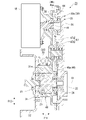
- the power system 1 of the present embodiment includes an engine 10 (drive source), a hydraulic pump 15 (driven device), and a clutch unit 20 (transmission unit). ..
- the engine 10 is, for example, an in-line four-cylinder internal combustion engine.
- the engine 10 houses the crankshaft 12 (drive shaft) in the crankcase 11.
- an output shaft 13 coaxial with the crankshaft 12 is projected to the outside of the crankcase 11.
- the output shaft 13 outputs a rotational driving force as the engine 10 operates.
- a hydraulic pump 15 is connected to the output shaft 13 via a hydraulic clutch 24 (transmission device) provided in the clutch unit 20.
- the hydraulic pump 15 is driven by inputting rotational power from at least one of the engine 10 and the motor generator 18 described later.
- the hydraulic pump 15 generates hydraulic pressure to be supplied to the outside by driving.
- the hydraulic pressure generated by the hydraulic pump 15 is supplied to, for example, a hydraulic actuator of a construction machine or an industrial machine.
- the hydraulic clutch 24 is connected by hydraulic pressure supply, and can transmit a rotational driving force between the output shaft 13 of the engine 10 and the input unit 16 (input shaft) of the hydraulic pump 15.
- the output shaft 13 may be referred to as an engine output shaft 13
- the input unit 16 may be referred to as an input shaft 16
- the hydraulic clutch 24 may be referred to as a clutch 24.
- the middle line C1 in the figure indicates the rotation center axis of the output shaft 13 and the input unit 16 coaxial with each other.
- the power system 1 is mounted on a vehicle with the axial direction of the output shaft 13 (direction along the axis C1 and arrow F11 in the figure) horizontal.
- the arrow F12 in the figure indicates the width direction orthogonal to the axial direction F11 and horizontal when mounted on the vehicle
- the arrow F13 in the figure indicates the axial direction F11 and the vertical direction orthogonal to the width direction and vertical when mounted on the vehicle.
- the power system 1 is mounted on a special vehicle such as a construction machine such as a hydraulic excavator or an industrial machine such as a forklift. Vehicles equipped with these are equipped with hydraulic actuators such as hydraulic cylinders and hydraulic motors. The power system 1 generates hydraulic pressure to be supplied to the hydraulic actuator of the mounted vehicle.
- a special vehicle such as a construction machine such as a hydraulic excavator or an industrial machine such as a forklift.
- Vehicles equipped with these are equipped with hydraulic actuators such as hydraulic cylinders and hydraulic motors.
- the power system 1 generates hydraulic pressure to be supplied to the hydraulic actuator of the mounted vehicle.
- the clutch unit 20 is arranged between the output shaft 13 of the engine 10 and the input unit 16 of the hydraulic pump 15.
- the clutch unit 20 is smaller than the engine 10 and can be easily replaced with a different engine 10.
- the input unit 16 of the hydraulic pump 15 is a rotating element arranged coaxially with the output shaft 13 of the engine 10.
- the clutch unit 20 includes a clutch 24 for connecting and disconnecting power transmission between the output shaft 13 of the engine 10 and the input unit 16 of the hydraulic pump 15. The clutch 24 switches whether or not power transmission is possible between the output shaft 13 of the engine 10 and the input unit 16 of the hydraulic pump 15.
- the clutch unit 20 includes a transmission case 30 that houses the clutch 24 and the like.
- the transmission case 30 is arranged between the engine 10 and the hydraulic pump 15 in the axial direction F11 of the output shaft 13.
- the transmission case 30 is larger than the cylindrical case portion 31 and the cylindrical case portion 31 that accommodate the output shaft 13 of the engine 10 and a rotating element coaxial with the output shaft 13.
- the wheel housing 32 which has a diameter and is arranged on the engine 10 side of the cylindrical case portion 31 and accommodates the fly wheel 13a provided on the output shaft 13, and the cylindrical case portion 31 are arranged on the hydraulic pump 15 side.
- a flat case portion 33 having a flat shape in which the width in the axial direction F11 is narrower than the widths in the width direction F12 and the vertical direction F13 is provided.
- the flat case portion 33 extends while widening the width in the vertical direction toward one side in the width direction when viewed from the axial direction F11.
- the flat case portion 33 has a substantially triangular shape when viewed from the axial direction F11.
- the portion of the flat case portion 33 on one side in the width direction projects to one side in the width direction with respect to the wheel housing 32 in the axial direction.
- This overhanging portion is referred to as an overhanging portion 34.
- the side surface of the flat case portion 33 facing the engine 10 side in the axial direction is referred to as a first side surface 35
- the side surface of the flat case portion 33 facing the hydraulic pump 15 side in the axial direction is referred to as a second side surface 36.
- the first side surface 35 and the second side surface 36 have a planar shape orthogonal to the axial direction.
- the wheel housing 32 In the axial direction F11, at least a part (in the present embodiment) of the wheel housing 32 is arranged on the engine 10 side (engine 10 side rather than the first side surface 35) of the flat case portion 33.
- the motor generator (second drive source) 18 (the present embodiment) is on the engine 10 side (the engine 10 side of the first side surface 35) of the overhanging portion 34 of the flat case portion 33. Then the whole) is arranged.
- the hydraulic regulator 60 and the oil passage switching valve 70 of the oil supply control device 50 which will be described later, are further arranged on the engine 10 side (the engine 10 side of the first side surface 35) of the flat case portion 33. ing.
- the motor generator 18 is configured as, for example, an MR motor.
- the motor generator 18 is connected to an in-vehicle power supply (secondary battery) via an inverter (not shown).
- the motor generator 18 functions as an electric motor that generates a second driving force separately from the engine 10 according to the power supply from the vehicle-mounted power source.
- the motor generator 18 functions as a generator that generates electric power in response to power transmission from the engine 10. For example, the electric power generated by the motor generator 18 is charged to the vehicle-mounted power source.
- the electric power transmitted and received between the motor generator 18 and the vehicle-mounted power supply is adjusted by an inverter (not shown).
- the power system 1 includes a control unit 17 as an electronic control unit (ECU).
- the control unit 17 includes an arithmetic processing circuit that performs various arithmetic processing related to driving the engine 10 and the like, and a storage device that stores control programs and data.
- This detection signal includes the rotation speed of the engine 10 (for example, the rotation speed of the crank shaft), various temperatures of the engine 10, the accelerator operation amount (output required amount), the vehicle state such as the vehicle speed, the storage amount of the in-vehicle power supply, and the like. It has been. Based on these detection signals, the control unit 17 controls the operation of the power system 1.
- This operation control includes operation control of the engine 10, power running and regeneration (power generation) control of the motor generator 18, and control of the solenoid valve of the oil supply control device 50.
- the motor generator 18 is connected to the engine 10 so as to be able to transmit power via the clutch 24.
- the motor generator 18 can transmit power to the engine 10 when the clutch is engaged, and cannot transmit power to the engine 10 when the clutch is disengaged.
- the motor generator 18 is always connected to the hydraulic pump 15 so as to be able to transmit power without using the clutch 24.
- the power system 1 switches whether or not power transmission is possible between the engine 10 and the hydraulic pump 15 and between the engine 10 and the motor generator 18 by engaging and disengaging the clutch 24.
- the clutch 24 When the clutch 24 is in the engaged state, power transmission is possible between the engine 10 and the hydraulic pump 15 and between the engine 10 and the motor generator 18.
- the clutch 24 When the clutch 24 is in the disengaged state, power transmission becomes impossible between the engine 10 and the hydraulic pump 15 and between the engine 10 and the motor generator 18.
- the power system 1 can be operated in the following first, second and third operation modes by the control accompanied by the engagement and disengagement of the clutch 24.
- the clutch unit 20 switches the power transmission path so that the power for driving the hydraulic pump 15 is transmitted from at least one of the engine 10 and the motor generator 18.
- the clutch 24 In the first operation mode (engine drive mode (charge mode)), the clutch 24 is engaged, the hydraulic pump 15 is driven by driving the engine 10, and the motor generator 18 is driven by driving the engine 10. That is, it is possible to drive the hydraulic pump 15 by the engine 10 to generate hydraulic pressure while the motor generator 18 is driven by the engine 10 to generate electric power. As a result, it is possible to drive the vehicle or the like with the output of the hydraulic pump 15 while charging the vehicle-mounted power supply. Further, if the configuration is such that the kinetic energy of the vehicle can be input from the output shaft 13 to the motor generator 18, the first operation mode is also a regeneration mode in which the kinetic energy of the vehicle is regenerated into electricity.
- the clutch 24 is connected and the hydraulic pump 15 is driven by driving both the engine 10 and the motor generator 18. That is, it is possible to drive the hydraulic pump 15 with the power of both the engine 10 and the motor to generate hydraulic pressure. As a result, the drive of the hydraulic pump 15 by the engine 10 is assisted by the motor generator 18, and a high output can be obtained.
- the clutch 24 is disengaged, the engine 10 is stopped, only the motor generator 18 is driven, and the hydraulic pump 15 is driven by the drive of the motor generator 18. That is, it is possible to stop the engine 10 and drive the hydraulic pump 15 only by driving the motor generator 18 to generate hydraulic pressure. As a result, it is possible to obtain hydraulic pressure by driving the hydraulic pump 15 by the motor generator 18 with the engine 10 stopped.
- the clutch unit 20 includes a clutch 24 that is operated by hydraulic pressure supply and an oil supply control device 50 that controls the supply of hydraulic oil to the clutch 24.
- the clutch unit 20 is rotatably connected to a first connecting shaft 21 connected to an output shaft 13 of an engine 10 and a second connecting rotatably connected to an input portion 16 of a hydraulic pump 15.
- the shaft 22 and the like are provided.
- the first connecting shaft 21 is arranged coaxially with the output shaft 13 of the engine 10 and always rotates integrally with the output shaft 13.
- the second connecting shaft 22 is arranged coaxially with the input portion 16 of the hydraulic pump 15 and always rotates integrally with the input shaft.
- the first connecting shaft 21 and the second connecting shaft 22 are arranged coaxially with each other, and a clutch 24 is provided between the first connecting shaft 21 and the second connecting shaft 22.
- the first connecting shaft 21 and the second connecting shaft 22 are connected so as to be able to connect and disconnect power transmission via the clutch 24.
- the clutch 24 operates by being supplied with hydraulic pressure from the outside (oil pump 14).
- the clutch 24 is a normally open type hydraulic clutch.
- the clutch 24 is in a connected state (a state in which power can be transmitted between the engine 10 and the hydraulic pump 15) by supplying hydraulic pressure from the outside.
- the clutch 24 is in a disengaged state (a state in which power transmission between the engine 10 and the hydraulic pump 15 is impossible) due to the loss of the hydraulic pressure supply from the outside.
- the clutch 24 is a multi-plate clutch provided with a plurality of disc-shaped friction plates (clutch plates) coaxial with the output shaft 13.
- the oil supply control device 50 controls (adjusts) the oil (hydraulic pressure) discharged by the oil pump 14 linked to the engine 10 to a constant pressure and outputs it.
- the oil supply control device 50 supplies a constant pressure-adjusted hydraulic pressure to the clutch 24.
- the oil pump 14 is integrally provided with the engine 10.
- the oil pump 14 is driven by driving the engine 10.
- the oil pump 14 is always driven in conjunction with the crankshaft 12 after the engine is started.
- the engine 10 increases the number of revolutions in response to an increase in output demand.
- the oil pump 14 increases the discharge amount as the engine speed increases.
- the flow rate of oil returned from the oil supply control device 50 to the upstream side of the oil pump 14 increases as the engine speed increases.
- the flat case portion 33 of the transmission case 30 extends in the vertical direction while widening toward one side in the width direction when viewed from the axial direction F11.
- the flat case portion 33 has a substantially triangular shape when viewed from the axial direction F11.
- the flat case portion 33 includes a circular first circular portion 37 centered on the output shaft 13 and a second circular portion 38 arranged vertically at a position separated from the first circular portion 37 on one side in the width direction.
- the third circular portion 39 are formed.
- a lower side portion 42 along the line and a side side portion 43 along the tangent line tangent to the second circular portion 38 and the third circular portion 39 from one side in the width direction are formed.
- a cylindrical case portion 31 projecting toward the engine 10 from the first side surface 35 is provided on the engine 10 side on the other side in the width direction of the flat case portion 33.
- a clutch fluid which is a clutch operating oil, is stored inside the transmission case 30.
- the transmission case 30 also serves as an oil tank 30a for storing the clutch fluid.
- the motor generator 18 includes an output shaft (second output shaft, hereinafter may be referred to as a motor output shaft) 19 parallel to the output shaft 13 of the engine 10.
- the motor generator 18 generates a second driving force separately from the engine 10.
- the motor output shaft 19 of the motor generator 18 is offset in the radial direction with respect to the output shaft 13 of the engine 10.
- the motor output shaft 19 is offset diagonally upward in the radial direction with respect to the output shaft 13.
- the motor output shaft 19 and thus the motor generator 18 are arranged at positions avoiding the connecting element 23 and the connecting case portion 48, which will be described later, when viewed from the axial direction of the output shafts 13 and 19.
- a transmission gear train (transmission mechanism) 44 is configured between the motor generator 18 and the hydraulic pump 15.
- the transmission gear train 44 enables power transmission between the output shaft 13 of the engine 10 and the motor output shaft 19.
- the transmission gear train 44 accelerates the rotation of the output shaft 13 of the engine 10 and transmits the rotation to the motor output shaft 19.
- the transmission gear train 44 reduces the rotation of the motor output shaft 19 so that it can be transmitted to the output shaft 13 of the engine 10.
- the transmission gear train 44 is between the first gear shaft 45 coaxial with the motor output shaft 19, the second gear shaft 46 coaxial with the input portion 16 of the hydraulic pump 15, and the first gear shaft 45 and the second gear shaft 46. It is provided with a relay gear shaft 47 arranged in the.
- the first transmission gear 45a is integrally provided on the first gear shaft 45.
- the second transmission gear 46a is integrally provided on the second gear shaft 46.
- the relay gear shaft 47 is provided with a first relay gear 47a that meshes with the first transmission gear 45a and a second relay gear 47b that meshes with the second transmission gear 46a so as to be integrally rotatable.
- the first transmission gear 45a has a smaller diameter than the first relay gear 47a.
- the second relay gear 47b has a smaller diameter than the second transmission gear 46a.
- the driving force of the motor generator 18 is decelerated between the first transmission gear 45a and the first relay gear 47a, and is also decelerated between the second relay gear 47b and the second transmission gear 46a, so that the hydraulic pressure is increased. It is transmitted to the pump 15.
- the clutch When the clutch is engaged, the driving force of the engine 10 is accelerated between the second transmission gear 46a and the second relay gear 47b, and also between the first relay gear 47a and the first transmission gear 45a. Is transmitted to the motor generator 18.
- the connecting element 23 is a rotating element that integrally rotatably connects the output shaft 13 of the engine 10 and the input unit 16 of the hydraulic pump 15.
- the connecting element 23 includes first and second connecting shafts 21 and 22, and a clutch 24 that engages and disconnects power transmission between these connecting shafts 21 and 22.
- the connecting element 23 is housed in the connecting case portion 48.
- the connecting case portion 48 is a non-rotating element that does not rotate with respect to the main body (framework) of the engine 10 and the hydraulic pump 15.
- the connecting case portion 48 includes a first circular portion 37 of the transmission case, a tubular case portion 31, and a wheel housing 32.
- the clutch unit 20 having the component arrangement structure connects the output shaft 13 of the engine 10 and the input shaft 16 of the hydraulic pump 15 driven by the driving force of the engine 10 so as to be able to transmit power.
- the connecting element 23 is provided with a motor generator 18 that generates a driving force separately from the engine 10, and the motor generator 18 is arranged so as to avoid the connecting element 23 when viewed from the axial direction of the output shaft 13.
- the power system 1 of the present embodiment includes the clutch unit 20, the engine 10, and the hydraulic pump 15.
- the motor generator 18 is arranged offset with respect to the connecting element 23 of the engine 10 and the hydraulic pump 15, so that the motor generator 18 is transmitted as compared with the case where the motor generator 18 is arranged coaxially with the engine 10. It is possible to suppress an increase in the axial width of the unit and the power system provided with the unit. Further, as compared with the case where the motor generator 18 is sandwiched between the output shaft 13 of the engine 10 and the input shaft 16 of the hydraulic pump 15, the motor generator 18 can be easily accessed from the outside, and maintainability can be improved. ..
- the motor generator 18 has a motor output shaft 19 offset with respect to the output shaft 13, and drives the output shaft 13 between the output shaft 13 and the motor output shaft 19.
- a transmission mechanism 44 capable of increasing the force and transmitting the force to the motor output shaft 19 is provided. According to this configuration, since the driving force of the engine 10 can be increased and transmitted to the motor generator 18, it is possible to increase the amount of power generation of the motor generator 18. Further, since the driving force of the motor generator 18 is decelerated and transmitted to the engine 10 and the hydraulic pump 15, the output of the motor generator 18 can be suppressed. Therefore, the size and weight of the motor generator 18 can be reduced.
- a transmission mechanism 44 capable of transmitting power is provided between the output shaft 13 and the motor output shaft 19, and a transmission case 30 for accommodating the transmission mechanism 44 is provided.
- a wheel housing 32 for accommodating a flywheel 13a that rotates integrally with the output shaft 13 is provided in a portion on the engine 10 side, and the motor generator 18 is provided in a portion on the engine 10 side of the transmission case 30. It is arranged avoiding 32. According to this configuration, the wheel housing 32 and the motor generator 18 can be efficiently arranged at the portion of the transmission case 30 on the engine 10 side, and the clutch unit 20 can be miniaturized.
- the transmission case 30 is formed in a flat shape in which the width in the axial direction F11 is narrower than the width in the orthogonal direction (width direction F12 and vertical direction F13) orthogonal to the axial direction F11.
- a flat case portion 33 is provided between the engine 10 and the hydraulic pump 15 in the direction F11.
- the transmission case 30 is provided with a flattened case portion 33 arranged between the engine 10 and the hydraulic pump 15 in a flattened shape with the width of the axial direction F11 suppressed, whereby the oil tank 30a is provided.
- the clutch unit 20 can be arranged without significantly separating the engine 10 and the driven portion while securing the capacity as much as possible.
- the wheel housing 32 and the motor generator 18 are arranged at a portion of the flat case portion 33 on the engine 10 side. According to this configuration, since the wheel housing 32 and the motor generator 18 are centrally arranged in the portion of the flat case portion 33 on the engine 10 side, the wheel housing 32 and the motor generator 18 are arranged on the shaft of the flat case portion 33.
- the clutch unit 20 can be made more compact than the case where the clutch units 20 are distributed and arranged on both sides in the direction.
- the connecting element 23 includes a clutch 24 that engages and disconnects power transmission between the engine 10 and the hydraulic pump 15, and the motor generator 18 is connected to the engine 10 via the clutch 24.
- the motor generator 18 is connected so as to be able to transmit power, and the motor generator 18 is connected to the hydraulic pump 15 so as to be able to transmit power without via the clutch 24.
- the hydraulic pump 15 can be driven by the engine 10 and the motor generator 18 can be driven to generate electric power.
- the motor generator 18 can assist the driving of the engine 10.
- the hydraulic pump 15 can be driven only by the motor generator 18 while the engine 10 is stopped.
- connection structure of the engine 10, the clutch unit 20, and the hydraulic pump 15 according to the second embodiment of the present invention will be described with reference to FIGS. 6 to 8.
- FIGS. 6 to 8 For convenience of illustration, there are some differences between the configurations of FIGS. 1 to 5 and the configurations of FIGS. 6 to 8.
- a flywheel 13a is provided at the axially outer end of the output shaft 13 of the engine 10.
- a first connecting portion 11a is provided on the lateral outer portion of the flywheel 13a in the axial direction.
- the first connecting portion 11a is a connecting portion for connecting a partner (for example, an input shaft 16) for transmitting a driving force from the output shaft 13 to the output shaft 13.
- a second connecting portion 15a that can be connected to the first connecting portion 11a is provided on the outer side of the input portion 16 of the hydraulic pump 15 in the axial direction.
- the second connecting portion 15a is a connecting portion for connecting a partner (for example, an output shaft 13) that transmits a driving force to the input shaft 16 to the input shaft 16.
- the output shaft 13 of the engine 10 and the input shaft 16 of the hydraulic pump 15 can be directly connected by the first and second connecting portions 11a and 15a.
- the first and second connecting portions 11a and 15a are detachably connected by using a plurality of fasteners such as bolts and nuts. By connecting the first and second connecting portions 11a and 15a, power can be transmitted between the input / output shafts 13 and 16.
- the connecting element 23 of the clutch unit 20 is interposed between the first and second connecting portions 11a and 15a.
- the first and second connecting portions 11a and 15a are indirectly connected via the connecting element 23.
- rotational power can be transmitted between the input / output shafts 13 and 16 via the connecting element 23.
- a drive-side connecting portion 23a that can be connected to the first connecting portion 11a of the flywheel 13a is provided at one end in the axial direction of the connecting element 23 (the outer end of the first connecting shaft 21 located on the engine 10 side).
- the drive-side connecting portion 23a has the same shape as the second connecting portion 15a of the input shaft 16.
- the first connecting portion 11a and the driving side connecting portion 23a are detachably connected by using fasteners such as a plurality of bolts and nuts.
- the first connecting shaft 21 may be composed of a plurality of parts splined with each other.
- a driven side connecting portion 23b that can be connected to the second connecting portion 15a of the input shaft 16 is provided.
- the driven side connecting portion 23b has the same shape as the first connecting portion 11a of the flywheel 13a.
- the second connecting portion 15a and the driven side connecting portion 23b are detachably connected using fasteners such as a plurality of bolts and nuts.
- the second connecting shaft 22 may be composed of a plurality of parts splined with each other.
- a wheel portion 23c similar to the flywheel 13a may be provided around the driven side connecting portion 23b.
- Each connecting portion 23a, 23b of the connecting element 23 interposed between the first and second connecting portions 11a, 15a has the following configuration. That is, the drive-side connecting portion 23a connected to the first connecting portion 11a in the connecting element 23 has the same shape as the second connecting portion 15a, and is connected to the second connecting portion 15a in the connecting element 23.
- the connecting portion 23b has the same shape as the first connecting portion 11a.
- the connecting portions 23a and 23b are not limited to the same shape as described above.
- the connecting portions 23a and 23b may be configured to be connected to the first and second connecting portions 11a and 15a so as to be able to transmit power.
- a drive-side case connecting portion 48a is provided at one end in the axial direction of the connecting case portion 48 accommodating the connecting element 23 (the outer peripheral portion of the open end on the engine 10 side of the wheel housing 32).
- the drive-side case connecting portion 48a is in the form of a flange extending to the outer periphery of the open end of the wheel housing 32.
- a first skeleton connecting portion 11c is provided around the first connecting portion 11a of the output shaft 13 on the outer surface of the skeleton of the engine 10 (for example, the crankcase 11).
- the first skeleton connecting portion 11c is provided on the outer peripheral portion of the closing plate 11b that intersects the axial direction.
- the first skeleton connecting portion 11c and the drive side case connecting portion 48a are detachably connected to each other by using fasteners such as a plurality of bolts and nuts.
- a housing 15b similar to the wheel housing 32 is provided around the second connecting portion 15a of the input portion 16 in the skeleton (pump body) of the hydraulic pump 15.
- the housing 15b accommodates the flywheel 13a inside when the hydraulic pump 15 is directly connected to the engine 10.
- a second skeleton connecting portion 15c is provided on the outer peripheral portion of the open end of the housing 15b on the engine 10 side.
- the second skeleton connecting portion 15c is in the form of a flange extending to the outer periphery of the open end of the housing 15b.
- the second skeleton connecting portion 15c has the same shape as the driving side case connecting portion 48a of the connecting case portion 48.
- a driven side case connecting portion 48c is provided at the other end in the axial direction of the connecting case portion 48 (the end on the hydraulic pump 15 side). At the other end of the connecting case portion 48 in the axial direction, a closing plate 48b similar to the closing plate 11b of the engine 10 is provided.
- the driven side case connecting portion 48c is provided on the outer peripheral portion of the closing plate 48b.
- the driven side case connecting portion 48c and the second skeleton connecting portion 15c are detachably connected to each other by using fasteners such as a plurality of bolts and nuts.
- the driven side case connecting portion 48c has the same shape as the first skeleton connecting portion 11c of the engine 10.
- the first skeleton connecting portion 11c of the engine 10 and the second skeleton connecting portion 15c of the hydraulic pump 15 can be directly connected.
- the connecting case portion 48 of the clutch unit 20 is interposed between the first and second skeleton connecting portions 11c and 15c.
- the first and second skeleton connecting portions 11c and 15c are indirectly connected via the connecting case portion 48.
- Each connecting portion 48a, 48c of the connecting case portion 48 has the following configuration. That is, in the connecting case portion 48, the drive side case connecting portion 48a connected to the first skeleton connecting portion 11c of the engine 10 has the same shape as the second skeleton connecting portion 15c of the hydraulic pump 15, and the hydraulic pump 15 has the same shape.
- the driven side case connecting portion 48c connected to the second skeleton connecting portion 15c has the same shape as the first skeleton connecting portion 11c of the engine 10.
- connection portion 48a and 48c are not limited to the same shape as described above.
- the connecting portions 48a and 48c may be configured to be integrally connected to the first and second skeleton connecting portions 11c and 15c.
- the clutch unit 20 having the above-mentioned connection structure connects the output shaft 13 of the engine 10 and the input shaft 16 of the hydraulic pump 15 driven by the driving force of the engine 10 so as to be able to transmit power.
- a connecting element 23 and a motor generator 18 that generates a driving force separately from the engine 10 are provided, and the connecting element 23 is connected to a first connecting portion 11a provided on the output shaft 13.
- a driven side connecting portion 23b provided on the input shaft 16 and connected to a second connecting portion 15a that can be connected to the first connecting portion 11a is provided.
- the power system 1 of the embodiment includes the clutch unit 20, the engine 10, and the hydraulic pump 15.
- each connecting portion of the engine 10 and the hydraulic pump 15 that can be connected to each other is changed or separately.
- the clutch unit 20 can be installed without interposing parts.
- the clutch unit 20 can be installed by using each connecting portion of the engine 10 and the hydraulic pump 15, and the existing power system can be efficiently hybridized.
- the driven side connecting portion 23b has the same shape as the first connecting portion 11a. According to this configuration, since the driven side connecting portion 23b of the clutch unit 20 has the same shape as the first connecting portion 11a of the engine 10, the second connecting portion 15a of the hydraulic pump 15 is changed or another part is interposed. It is possible to install the clutch unit 20 without doing anything. As a result, the existing power system can be efficiently hybridized.
- the clutch unit 20 includes a connecting case portion 48 for accommodating the connecting element 23, and the connecting case portion 48 is connected to a drive-side case connected to a first skeleton connecting portion 11c provided on the skeleton of the engine 10.
- the portion 48a is provided with a driven side case connecting portion 48c provided on the skeleton of the hydraulic pump 15 and connected to a second skeleton connecting portion 15c that can be connected to the first skeleton connecting portion 11c.
- the driven side case connecting portion 48c has the same shape as the first skeleton connecting portion 11c. According to this configuration, since the driven side case connecting portion 48c of the clutch unit 20 has the same shape as the first skeleton connecting portion 11c of the engine 10, the second skeleton connecting portion 15c of the hydraulic pump 15 can be changed or another part. It is possible to install the clutch unit 20 without interposing the clutch unit 20. As a result, the existing power system can be efficiently hybridized.
- the connecting element 23 includes a clutch 24 that engages and disconnects power transmission between the engine 10 and the hydraulic pump 15, and the motor generator 18 is connected to the engine 10 via the clutch 24. It is connected so as to be able to transmit power, and is connected to the hydraulic pump 15 so as to be able to transmit power without using the clutch 24.
- the hydraulic pump 15 can be driven by the engine 10 and the motor generator 18 can be driven to generate electric power.
- the motor generator 18 can assist the driving of the engine 10.
- the hydraulic pump 15 can be driven only by the motor generator 18 while the engine 10 is stopped.
- the present invention is not limited to the above embodiment, and for example, the drive source is not limited to the engine 10 (internal combustion engine) and may be an electric motor.
- the clutch 24 may be a normally closed type that is disconnected by hydraulic pressure supply instead of a normally open type that is connected by hydraulic pressure supply.
- the transmission device is not limited to the clutch 24 that connects and disconnects the power transmission, and may be a clutch that controls the shifting operation of the transmission. Further, the transmission device may be a transmission that shifts and operates by hydraulic pressure supply.
- the configuration in the above embodiment is an example of the present invention, and various changes can be made without departing from the gist of the present invention, such as replacing the constituent elements of the above embodiment with well-known constituent elements.
- the second drive source is arranged coaxially with the drive source by arranging the second drive source at an offset with respect to the connecting element of the drive source and the driven device. It is possible to suppress an increase in the axial width of the transmission unit and the power system provided with the transmission unit as compared with the case where the transmission unit is arranged. Further, compared to the case where the second drive source is sandwiched between the output shaft of the drive source and the input shaft of the driven device, the second drive source can be easily accessed from the outside, and maintainability is improved. Can be done.
Landscapes
- Engineering & Computer Science (AREA)
- Mechanical Engineering (AREA)
- Chemical & Material Sciences (AREA)
- Combustion & Propulsion (AREA)
- Transportation (AREA)
- General Engineering & Computer Science (AREA)
- Hybrid Electric Vehicles (AREA)
- Arrangement Of Transmissions (AREA)
- Arrangement And Driving Of Transmission Devices (AREA)
- Arrangement Or Mounting Of Propulsion Units For Vehicles (AREA)
- General Details Of Gearings (AREA)
Priority Applications (3)
| Application Number | Priority Date | Filing Date | Title |
|---|---|---|---|
| EP21906387.2A EP4265456A4 (en) | 2020-12-18 | 2021-12-03 | TRANSMISSION UNIT AND POWER SYSTEM |
| US18/033,744 US20230398853A1 (en) | 2020-12-18 | 2021-12-03 | Transmission unit and power system |
| CN202180072589.4A CN116529114A (zh) | 2020-12-18 | 2021-12-03 | 传动单元及动力系统 |
Applications Claiming Priority (2)
| Application Number | Priority Date | Filing Date | Title |
|---|---|---|---|
| JP2020-210699 | 2020-12-18 | ||
| JP2020210699A JP7497285B2 (ja) | 2020-12-18 | 2020-12-18 | 伝動ユニットおよび動力システム |
Publications (1)
| Publication Number | Publication Date |
|---|---|
| WO2022131024A1 true WO2022131024A1 (ja) | 2022-06-23 |
Family
ID=82057640
Family Applications (1)
| Application Number | Title | Priority Date | Filing Date |
|---|---|---|---|
| PCT/JP2021/044478 Ceased WO2022131024A1 (ja) | 2020-12-18 | 2021-12-03 | 伝動ユニットおよび動力システム |
Country Status (5)
| Country | Link |
|---|---|
| US (1) | US20230398853A1 (https=) |
| EP (1) | EP4265456A4 (https=) |
| JP (1) | JP7497285B2 (https=) |
| CN (1) | CN116529114A (https=) |
| WO (1) | WO2022131024A1 (https=) |
Families Citing this family (4)
| Publication number | Priority date | Publication date | Assignee | Title |
|---|---|---|---|---|
| EP4253177B1 (en) * | 2020-11-27 | 2025-11-26 | Kubota Corporation | Hybrid system |
| JP7604584B1 (ja) | 2023-09-12 | 2024-12-23 | 本田技研工業株式会社 | 車両駆動装置 |
| JP2026011287A (ja) * | 2024-07-11 | 2026-01-23 | スズキ株式会社 | ハイブリッド車両の動力伝達装置 |
| JP2026011286A (ja) * | 2024-07-11 | 2026-01-23 | スズキ株式会社 | ハイブリッド車両の動力伝達装置 |
Citations (5)
| Publication number | Priority date | Publication date | Assignee | Title |
|---|---|---|---|---|
| JP2010533620A (ja) * | 2007-07-17 | 2010-10-28 | ルノー・トラックス | 最適化されたエネルギ回収システムを備えるパワートレイン |
| JP2014133455A (ja) * | 2013-01-09 | 2014-07-24 | Hitachi Constr Mach Co Ltd | 建設機械の油圧ポンプ駆動装置 |
| JP2015182512A (ja) * | 2014-03-20 | 2015-10-22 | ヤンマー株式会社 | ハイブリッド式エンジン装置 |
| JP2020093639A (ja) | 2018-12-12 | 2020-06-18 | トヨタ自動車株式会社 | ハイブリッド車両 |
| JP2020093638A (ja) | 2018-12-12 | 2020-06-18 | トヨタ自動車株式会社 | ハイブリッド車両 |
Family Cites Families (15)
| Publication number | Priority date | Publication date | Assignee | Title |
|---|---|---|---|---|
| JP4483819B2 (ja) * | 2005-04-28 | 2010-06-16 | 株式会社豊田中央研究所 | 動力伝達システム |
| US7681676B2 (en) * | 2006-01-23 | 2010-03-23 | Paul Harriman Kydd | Electric hybrid vehicle conversion |
| US7921950B2 (en) * | 2006-11-10 | 2011-04-12 | Clean Emissions Technologies, Inc. | Electric traction retrofit |
| DE102008052288A1 (de) * | 2008-10-18 | 2010-05-06 | Voith Patent Gmbh | Kraftfahrzeugantriebsstrang |
| WO2011150297A2 (en) * | 2010-05-26 | 2011-12-01 | Ares Transportation Technologies | Power transmission system for hybrid vehicle |
| EP2468553A1 (en) * | 2010-12-21 | 2012-06-27 | Saab Automobile AB | A vehicle powertrain arrangement |
| US9527375B2 (en) * | 2014-08-20 | 2016-12-27 | Gm Global Technoogy Operations Llc | Powertrain with transmission-based motor/generator for engine starting and regenerative braking modes |
| DE102016212994A1 (de) * | 2016-07-15 | 2018-01-18 | Schaeffler Technologies AG & Co. KG | Kupplungseinheit, Hybridmodul und Antriebsstrang für ein Kraftfahrzeug |
| DE102016219380A1 (de) * | 2016-10-06 | 2018-04-12 | Continental Automotive Gmbh | Antriebsmodul für ein Kraftfahrzeug |
| US10173514B2 (en) * | 2016-11-01 | 2019-01-08 | GM Global Technology Operations LLC | Planetary axis transfer gearbox |
| US10239516B2 (en) * | 2016-12-14 | 2019-03-26 | Bendix Commercial Vehicle Systems Llc | Front end motor-generator system and hybrid electric vehicle operating method |
| US10479180B2 (en) * | 2016-12-14 | 2019-11-19 | Bendix Commercial Vehicle Systems Llc | Front end motor-generator system and hybrid electric vehicle operating method |
| US10220831B2 (en) * | 2016-12-14 | 2019-03-05 | Bendix Commercial Vehicle Systems Llc | Front end motor-generator system and hybrid electric vehicle operating method |
| US10363923B2 (en) * | 2016-12-14 | 2019-07-30 | Bendix Commercial Vehicle Systems, Llc | Front end motor-generator system and hybrid electric vehicle operating method |
| FR3080068B1 (fr) * | 2018-04-17 | 2020-09-04 | Valeo Embrayages | Systeme d'entrainement pour un vehicule automobile hybride et systeme de transmission comprenant un tel systeme d'entrainement |
-
2020
- 2020-12-18 JP JP2020210699A patent/JP7497285B2/ja active Active
-
2021
- 2021-12-03 EP EP21906387.2A patent/EP4265456A4/en active Pending
- 2021-12-03 WO PCT/JP2021/044478 patent/WO2022131024A1/ja not_active Ceased
- 2021-12-03 US US18/033,744 patent/US20230398853A1/en active Pending
- 2021-12-03 CN CN202180072589.4A patent/CN116529114A/zh active Pending
Patent Citations (5)
| Publication number | Priority date | Publication date | Assignee | Title |
|---|---|---|---|---|
| JP2010533620A (ja) * | 2007-07-17 | 2010-10-28 | ルノー・トラックス | 最適化されたエネルギ回収システムを備えるパワートレイン |
| JP2014133455A (ja) * | 2013-01-09 | 2014-07-24 | Hitachi Constr Mach Co Ltd | 建設機械の油圧ポンプ駆動装置 |
| JP2015182512A (ja) * | 2014-03-20 | 2015-10-22 | ヤンマー株式会社 | ハイブリッド式エンジン装置 |
| JP2020093639A (ja) | 2018-12-12 | 2020-06-18 | トヨタ自動車株式会社 | ハイブリッド車両 |
| JP2020093638A (ja) | 2018-12-12 | 2020-06-18 | トヨタ自動車株式会社 | ハイブリッド車両 |
Non-Patent Citations (1)
| Title |
|---|
| See also references of EP4265456A4 |
Also Published As
| Publication number | Publication date |
|---|---|
| JP2022097237A (ja) | 2022-06-30 |
| EP4265456A4 (en) | 2024-11-27 |
| US20230398853A1 (en) | 2023-12-14 |
| JP7497285B2 (ja) | 2024-06-10 |
| CN116529114A (zh) | 2023-08-01 |
| EP4265456A1 (en) | 2023-10-25 |
Similar Documents
| Publication | Publication Date | Title |
|---|---|---|
| WO2022131024A1 (ja) | 伝動ユニットおよび動力システム | |
| CN100434299C (zh) | 混合动力车用驱动装置 | |
| CN100363197C (zh) | 机动车传动系、起动内燃机的方法和产生电流的方法 | |
| US8991283B2 (en) | Drive system for a motor vehicle and motor vehicle having such a drive system | |
| US10730387B2 (en) | Drive device for a hybrid-powered motor vehicle | |
| US9446763B2 (en) | Controlled gerotor actuated pre-trans parallel hybrid | |
| US9840141B2 (en) | Hybrid vehicle drive device | |
| CN101970272A (zh) | 混合动力车 | |
| US20190168601A1 (en) | Transaxle device | |
| WO2006054661A1 (ja) | ハイブリッド車用駆動装置 | |
| CN102465977A (zh) | 用于车辆的驱动系统 | |
| WO2018008141A1 (ja) | 動力伝達装置 | |
| US7780567B2 (en) | Input brake assembly | |
| US8696508B2 (en) | Drive mechanism | |
| JP5915008B2 (ja) | ハイブリッド車両 | |
| WO2022131025A1 (ja) | 伝動ユニットおよび動力システム | |
| US12351031B2 (en) | Compact P2 hybrid architecture | |
| US11738632B2 (en) | Hybrid drive sub-assembly for a vehicle | |
| US20220396139A1 (en) | Method for operating a vehicle and for decoupling a hybrid drive train from an energy supply of the vehicle | |
| JP2025511479A (ja) | ハイブリッド・パワー・アセンブリおよび車両 | |
| JP5375543B2 (ja) | ハイブリッド車両用駆動装置 | |
| EP4606613A1 (en) | Power transmission unit and power system | |
| CN121625756A (zh) | 混合驱动装置 | |
| JP5201080B2 (ja) | ハイブリッド車の駆動機構 |
Legal Events
| Date | Code | Title | Description |
|---|---|---|---|
| 121 | Ep: the epo has been informed by wipo that ep was designated in this application |
Ref document number: 21906387 Country of ref document: EP Kind code of ref document: A1 |
|
| WWE | Wipo information: entry into national phase |
Ref document number: 202180072589.4 Country of ref document: CN |
|
| NENP | Non-entry into the national phase |
Ref country code: DE |
|
| ENP | Entry into the national phase |
Ref document number: 2021906387 Country of ref document: EP Effective date: 20230718 |