WO2022124184A1 - 変倍光学系、光学機器及び変倍光学系の製造方法 - Google Patents
変倍光学系、光学機器及び変倍光学系の製造方法 Download PDFInfo
- Publication number
- WO2022124184A1 WO2022124184A1 PCT/JP2021/044213 JP2021044213W WO2022124184A1 WO 2022124184 A1 WO2022124184 A1 WO 2022124184A1 JP 2021044213 W JP2021044213 W JP 2021044213W WO 2022124184 A1 WO2022124184 A1 WO 2022124184A1
- Authority
- WO
- WIPO (PCT)
- Prior art keywords
- lens group
- lens
- group
- optical system
- variable magnification
- Prior art date
- Legal status (The legal status is an assumption and is not a legal conclusion. Google has not performed a legal analysis and makes no representation as to the accuracy of the status listed.)
- Ceased
Links
Images


Classifications
-
- G—PHYSICS
- G02—OPTICS
- G02B—OPTICAL ELEMENTS, SYSTEMS OR APPARATUS
- G02B15/00—Optical objectives with means for varying the magnification
- G02B15/14—Optical objectives with means for varying the magnification by axial movement of one or more lenses or groups of lenses relative to the image plane for continuously varying the equivalent focal length of the objective
- G02B15/16—Optical objectives with means for varying the magnification by axial movement of one or more lenses or groups of lenses relative to the image plane for continuously varying the equivalent focal length of the objective with interdependent non-linearly related movements between one lens or lens group, and another lens or lens group
- G02B15/20—Optical objectives with means for varying the magnification by axial movement of one or more lenses or groups of lenses relative to the image plane for continuously varying the equivalent focal length of the objective with interdependent non-linearly related movements between one lens or lens group, and another lens or lens group having an additional movable lens or lens group for varying the objective focal length
-
- G—PHYSICS
- G02—OPTICS
- G02B—OPTICAL ELEMENTS, SYSTEMS OR APPARATUS
- G02B13/00—Optical objectives specially designed for the purposes specified below
- G02B13/02—Telephoto objectives, i.e. systems of the type + - in which the distance from the front vertex to the image plane is less than the equivalent focal length
-
- G—PHYSICS
- G02—OPTICS
- G02B—OPTICAL ELEMENTS, SYSTEMS OR APPARATUS
- G02B15/00—Optical objectives with means for varying the magnification
- G02B15/14—Optical objectives with means for varying the magnification by axial movement of one or more lenses or groups of lenses relative to the image plane for continuously varying the equivalent focal length of the objective
- G02B15/145—Optical objectives with means for varying the magnification by axial movement of one or more lenses or groups of lenses relative to the image plane for continuously varying the equivalent focal length of the objective having five groups only
- G02B15/1451—Optical objectives with means for varying the magnification by axial movement of one or more lenses or groups of lenses relative to the image plane for continuously varying the equivalent focal length of the objective having five groups only the first group being positive
- G02B15/145121—Optical objectives with means for varying the magnification by axial movement of one or more lenses or groups of lenses relative to the image plane for continuously varying the equivalent focal length of the objective having five groups only the first group being positive arranged +-+-+
-
- G—PHYSICS
- G02—OPTICS
- G02B—OPTICAL ELEMENTS, SYSTEMS OR APPARATUS
- G02B15/00—Optical objectives with means for varying the magnification
- G02B15/14—Optical objectives with means for varying the magnification by axial movement of one or more lenses or groups of lenses relative to the image plane for continuously varying the equivalent focal length of the objective
- G02B15/146—Optical objectives with means for varying the magnification by axial movement of one or more lenses or groups of lenses relative to the image plane for continuously varying the equivalent focal length of the objective having more than five groups
- G02B15/1461—Optical objectives with means for varying the magnification by axial movement of one or more lenses or groups of lenses relative to the image plane for continuously varying the equivalent focal length of the objective having more than five groups the first group being positive
-
- G—PHYSICS
- G02—OPTICS
- G02B—OPTICAL ELEMENTS, SYSTEMS OR APPARATUS
- G02B27/00—Optical systems or apparatus not provided for by any of the groups G02B1/00 - G02B26/00, G02B30/00
- G02B27/64—Imaging systems using optical elements for stabilisation of the lateral and angular position of the image
- G02B27/646—Imaging systems using optical elements for stabilisation of the lateral and angular position of the image compensating for small deviations, e.g. due to vibration or shake
-
- G—PHYSICS
- G02—OPTICS
- G02B—OPTICAL ELEMENTS, SYSTEMS OR APPARATUS
- G02B13/00—Optical objectives specially designed for the purposes specified below
- G02B13/18—Optical objectives specially designed for the purposes specified below with lenses having one or more non-spherical faces, e.g. for reducing geometrical aberration
Definitions
- the present invention relates to a variable magnification optical system, an optical device, and a method for manufacturing the variable magnification optical system.
- Patent Document 1 In recent years, in telephoto variable magnification optical systems, it has been required to reduce the size and weight of the lens barrel (see Patent Document 1). However, the optical system described in Patent Document 1 is required to have further improved optical performance.
- the variable magnification optical system has a first lens group, a second lens group, and a rear group, which are arranged on the most object side and have a positive refractive power, and have a variable magnification.
- the distance between the lens groups changes, and the first lens group has a positive lens on the object side most, and satisfies the condition of the following equation. 0.30 ⁇ D1MAX / G1d ⁇ 0.70 however, D1MAX: Maximum air spacing on the optical axis in the first lens group G1d: Thickness on the optical axis of the first lens group
- variable magnification optical system has a first lens group, a second lens group, and a rear group, which are arranged on the most object side and have a positive refractive power.
- the spacing between the lens groups changes during scaling, and the first lens group has a positive lens on the most object side, satisfying the conditions of the following equation. 0.064 ⁇ D1MAX / f1 ⁇ 0.140 however, D1MAX: Maximum air spacing on the optical axis in the 1st lens group f1: Focal length of the 1st lens group
- the method for manufacturing a variable magnification optical system according to the first aspect of the present invention includes a first lens group having a positive refractive power, a second lens group, and a rear group, which are arranged on the most object side. It is a method for manufacturing a magnification optical system, in which the lenses are arranged so that the distance between each lens group changes at the time of magnification change, and the positive lens is arranged on the most object side of the first lens group, and the conditions of the following equation are satisfied. Arrange like this. 0.30 ⁇ D1MAX / G1d ⁇ 0.70 however, D1MAX: Maximum air spacing on the optical axis in the first lens group G1d: Thickness on the optical axis of the first lens group
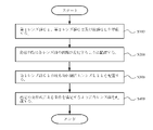
- variable magnification optical system is a diagram of various aberrations of the variable magnification optical system according to the eighth embodiment in the infinity in-focus state, where (a) shows a wide-angle end state and (b) shows a telephoto end state. It is sectional drawing of the camera equipped with the said variable magnification optical system. It is a flowchart for demonstrating the manufacturing method of the said variable magnification optical system.
- the variable magnification optical system ZL As shown in FIG. 1, the variable magnification optical system ZL according to the first embodiment has a first lens group G1 having a positive refractive power, a second lens group G2, and a rear group arranged on the most object side. It has GL, and the distance between each lens group changes at the time of scaling. Further, in this variable magnification optical system ZL, the first lens group G1 has a positive lens (for example, a biconvex positive lens L11 in the example of FIG. 1) on the most object side. With such a configuration, it is possible to reduce the size and weight of the variable magnification optical system ZL while ensuring the optical performance.
- a positive lens for example, a biconvex positive lens L11 in the example of FIG.
- variable magnification optical system ZL satisfies the conditional expression (1) shown below.
- D1MAX Maximum air spacing on the optical axis in the first lens group G1
- G1d Thickness on the optical axis of the first lens group G1
- the conditional expression (1) defines the ratio between the maximum air spacing in the first lens group G1 and the thickness on the optical axis of the first lens group G1. If the upper limit of the conditional expression (1) is exceeded, the thickness of the first lens group G1 on the optical axis becomes too thick, which makes it difficult to correct spherical aberration, axial chromatic aberration, chromatic aberration of magnification, and the like, which is not preferable. In order to ensure the effect of the conditional expression (1), the upper limit of the conditional expression (1) is set to 0.68, 0.65, 0.63, 0.60, 0.58, and further 0. It is more desirable to set it to 55.
- conditional expression (1) if it is less than the lower limit of the conditional expression (1), it is disadvantageous for miniaturization and weight reduction, and if it is attempted to reduce the size and weight, it becomes difficult to correct spherical aberration, coma aberration, curvature of field, and the like. Not preferred. In order to ensure the effect of the conditional expression (1), it is more desirable to set the lower limit value of the conditional expression (1) to 0.33 and further to 0.35.
- variable magnification optical system ZL satisfies the conditional expression (2) shown below.
- D1MAX Maximum air spacing on the optical axis in the first lens group G1 f1: Focal length of the first lens group G1
- Conditional expression (2) defines the ratio between the maximum air spacing in the first lens group G1 and the focal length of the first lens group G1. If the upper limit of the conditional equation (2) is exceeded, the thickness of the first lens group G1 on the optical axis becomes too thick, which makes it difficult to correct spherical aberration, axial chromatic aberration, chromatic aberration of magnification, etc., which is not preferable. In order to ensure the effect of the conditional expression (2), it is more desirable to set the upper limit values of the conditional expression (2) to 0.138, 0.135, 0.133, and further 0.130.
- conditional expression (2) if it falls below the lower limit of the conditional expression (2), it is disadvantageous for miniaturization and weight reduction, and if it is attempted to miniaturize and weight reduction, it becomes difficult to correct spherical aberration, coma aberration, curvature of field, and the like. Not preferred. In order to ensure the effect of the conditional expression (2), it is more desirable to set the lower limit values of the conditional expression (2) to 0.065, 0.068, and further 0.070.
- the variable magnification optical system ZL As shown in FIG. 1, the variable magnification optical system ZL according to the second embodiment has a first lens group G1 having a positive refractive power, a second lens group G2, and a rear group arranged on the most object side. It has GL, and the distance between each lens group changes at the time of scaling. Further, in this variable magnification optical system ZL, the first lens group G1 has a positive lens (for example, a biconvex positive lens L11 in the example of FIG. 1) on the most object side. With this configuration, the variable magnification optical system ZL can be made smaller and lighter.
- variable magnification optical system ZL according to the second embodiment satisfies the conditional expression (2) shown below.
- D1MAX Maximum air spacing on the optical axis in the first lens group G1 f1: Focal length of the first lens group G1
- Conditional expression (2) defines the ratio between the maximum air spacing in the first lens group G1 and the focal length of the first lens group G1. If the upper limit of the conditional equation (2) is exceeded, the thickness of the first lens group G1 on the optical axis becomes too thick, which makes it difficult to correct spherical aberration, axial chromatic aberration, chromatic aberration of magnification, etc., which is not preferable. In order to ensure the effect of the conditional expression (2), it is more desirable to set the upper limit values of the conditional expression (2) to 0.138, 0.135, 0.133, and further 0.130.
- conditional expression (2) if it falls below the lower limit of the conditional expression (2), it is disadvantageous for miniaturization and weight reduction, and if it is attempted to miniaturize and weight reduction, it becomes difficult to correct spherical aberration, coma aberration, curvature of field, and the like. Not preferred. In order to ensure the effect of the conditional expression (2), it is more desirable to set the lower limit values of the conditional expression (2) to 0.065, 0.068, and further 0.070.
- variable magnification optical system ZL (About the first embodiment and the second embodiment) Further, it is desirable that the variable magnification optical system ZL according to the first embodiment and the second embodiment (hereinafter referred to as “the present embodiment”) satisfies the conditional expression (3) shown below.
- Conditional expression (3) defines the ratio between the focal length of the first lens group G1 and the focal length of the entire system in the telephoto end state.
- variable magnification optical system ZL has a diaphragm (for example, an aperture diaphragm S shown in FIG. 1) in the rear group GL, and at least a part of the image plane side of the diaphragm has an optical axis. It is desirable that the vibration isolation group Gv moves so as to have components in orthogonal directions.
- variable magnification optical system ZL satisfies the conditional expression (4) shown below.
- ⁇ tv Lateral magnification of anti-vibration group Gv in the telephoto end state
- ⁇ tvb Lateral magnification of the group on the image plane side of the anti-vibration group Gv in the telephoto end state
- Conditional expression (4) defines the conditions for performing vibration isolation in the vibration isolation group Gv. By satisfying this conditional equation (4), it is possible to satisfactorily correct fluctuations in various aberrations such as coma, curvature of field, and astigmatism during vibration isolation. Further, if it is out of the range of the conditional expression (4), it becomes difficult to balance the correction of coma aberration, curvature of field, astigmatism, etc. at the time of vibration isolation while correcting various aberrations in the normal state, which is preferable. do not have.
- the upper limit of the conditional expression (4) should be 2.90, 2.80, 2.70, 2.60, and 2.50. Is more desirable. Further, in order to ensure the effect of the conditional expression (4), the lower limit of the conditional expression (4) is set to 1.60, 1.70, 1.80, 1.90, 2.00, 2.10. It is more desirable to set it to 2.20.
- the vibration isolation group Gv has a positive lens, a positive lens, and a negative lens in order from the object side. With this configuration, it is possible to correct fluctuations in various aberrations such as coma aberration during vibration isolation.
- variable magnification optical system ZL satisfies the conditional expression (5) shown below.
- Conditional expression (5) defines the ratio between the thickness of the anti-vibration group on the optical axis and the total optical length of this variable magnification optical system ZL in the telephoto end state.
- variable magnification optical system ZL has a diaphragm in the rear group GL, and at least a part of the image plane side of the diaphragm moves in the optical axis direction during focusing. It is desirable that it is Gf.
- variable magnification optical system ZL satisfies the conditional expression (6) shown below.
- ⁇ tf Lateral magnification of the in-focus group Gf in the telephoto end state
- ⁇ tfb Lateral magnification of the group on the image plane side of the in-focus group Gf in the telephoto end state
- Conditional expression (6) defines the conditions for focusing in the focusing group Gf.
- This conditional equation (6) it is possible to satisfactorily correct fluctuations in various aberrations such as spherical aberration, coma, curvature of field, and astigmatism during focusing. Further, if it is out of the range of the conditional equation (6), it is difficult to balance the correction of spherical aberration, coma, curvature of field, astigmatism, etc. at the time of focusing while correcting various aberrations in normal time. Therefore, it is not preferable.
- the upper limit of the conditional expression (6) should be -4.25, -4.50, -4.75, and further -5.00. Is more desirable.
- the lower limit values of the conditional expression (6) are set to -7.50, -7.00, -6.50, -6.00, -5. It is more desirable to set it to 80 and further to -5.50.
- variable magnification optical system ZL it is desirable that the focusing group Gf has a positive lens and a negative lens in order from the object side. With this configuration, it is possible to correct fluctuations in axial chromatic aberration and chromatic aberration of magnification during focusing.
- variable magnification optical system ZL satisfies the conditional expression (7) shown below.
- Conditional expression (7) defines the ratio between the thickness of the in-focus group Gf on the optical axis and the total optical length of this variable magnification optical system ZL in the telephoto end state.
- variable magnification optical system ZL it is desirable that the first lens group G1 has a negative lens on the most image plane side.
- the variable magnification optical system ZL can be made smaller and lighter by arranging the positive lens on the most object side of the first lens group G1 and further arranging the negative lens on the most image plane side. can.
- variable magnification optical system ZL satisfies the conditional expression (8) shown below.
- Conditional expression (8) defines the ratio between the thickness of the first lens group G1 on the optical axis and the focal length of the entire system of this variable magnification optical system ZL in the telephoto end state.
- conditional expression (8) In order to ensure the effect of the conditional expression (8), it is more desirable to set the upper limit values of the conditional expression (8) to 0.14, 0.13, and further 0.12. Further, if it falls below the lower limit of the conditional expression (8), it is disadvantageous for miniaturization and weight reduction, and it is difficult to correct various aberrations such as spherical aberration, coma aberration, and curvature of field when trying to reduce the size and weight. Therefore, it is not preferable. In order to ensure the effect of the conditional expression (8), it is more desirable to set the lower limit value of the conditional expression (8) to 0.05 and further preferably 0.055.
- the rear group GL has a lens group including an aperture (for example, the third lens group G3 in FIG. 1) and satisfies the conditional expression (9) shown below. It is desirable to do.
- Conditional expression (9) defines the ratio between the thickness of the lens group including the aperture on the optical axis and the optical total length of this variable magnification optical system ZL in the telephoto end state.
- the upper limit values of the conditional expression (9) In order to ensure the effect of the conditional expression (9), it is more desirable to set the upper limit values of the conditional expression (9) to 0.28, 0.25, 0.25, and further 0.20. Further, in order to ensure the effect of the conditional expression (9), the lower limit values of the conditional expression (9) shall be 0.06, 0.08, 0.10, 0.12, and further 0.13. Is more desirable.
- the first lens group G1 includes a negative lens arranged on the most image plane side and a positive lens arranged adjacent to the object side of the negative lens. It is desirable to have.
- the positive lens is arranged on the most object side of the first lens group G1
- the negative lens is arranged on the most image plane side
- the positive lens is arranged adjacent to the object side of the negative lens.
- the magnification optical system ZL can be made smaller and lighter.
- variable magnification optical system ZL satisfies the conditional expression (10) shown below.
- D1MAX Maximum air spacing on the optical axis in the first lens group
- G1 ft Focal length of the entire system in the telephoto end state of the variable magnification optical system ZL
- Conditional expression (10) defines the ratio between the maximum air spacing on the optical axis in the first lens group G1 and the focal length of the entire system of the variable magnification optical system ZL in the telephoto end state. By satisfying this conditional expression (10), it is possible to satisfactorily correct various aberrations. On the other hand, if the upper limit of the conditional expression (10) is exceeded, it becomes difficult to correct various aberrations such as spherical aberration, axial chromatic aberration, and chromatic aberration of magnification, which is not preferable. In order to ensure the effect of the conditional expression (10), the upper limit of the conditional expression (10) is 0.075, 0.070, 0.065, 0.060, 0.058, and further 0.
- conditional expression (10) it is more desirable to set it to 0.055. Further, if it falls below the lower limit of the conditional expression (10), it is disadvantageous for miniaturization and weight reduction, and it is difficult to correct various aberrations such as spherical aberration, coma aberration, and curvature of field when trying to reduce the size and weight. Therefore, it is not preferable. In order to ensure the effect of the conditional expression (10), it is more desirable to set the lower limit values of the conditional expression (10) to 0.016, 0.018, and further 0.020.
- variable magnification optical system ZL satisfies the conditional expression (11) shown below.
- Conditional expression (11) defines the ratio between the back focus of the variable magnification optical system ZL in the wide-angle end state and the focal length of the entire system. In order to ensure the effect of the conditional expression (11), it is more desirable to set the upper limit values of the conditional expression (11) to 0.48, 0.45, 0.43, and further 0.40. .. Further, in order to ensure the effect of the conditional expression (11), the lower limit values of the conditional expression (11) shall be 0.18, 0.20, 0.23, 0.25, and further 0.28. Is more desirable.
- variable magnification optical system ZL satisfies the conditional expression (12) shown below.
- the conditional expression (12) defines the range of the half angle of view of the variable magnification optical system ZL in the wide-angle end state.
- the upper limit values of the conditional expression (12) are set to 9.50 °, 9.00 °, 8.80 °, 8.50 °, 8. It is more desirable to set the temperature to 30 ° and further to 8.00 °.
- the lower limit values of the conditional expression (12) are set to 4.30 °, 4.50 °, 4.80 °, 5.00 °, 5.30. It is more desirable to set the temperature to 5.50 °.
- the rear group GL has a positive lens group, a positive lens group, and a negative lens group in order from the object side. Further, at least a part of at least one of the positive lens group, the positive lens group, and the negative lens group of the rear group GL is an anti-vibration group Gv that moves so as to have a component in a direction orthogonal to the optical axis. It is desirable that at least a part of at least one of the positive lens group, the positive lens group, and the negative lens group is the focusing group Gf that moves in the optical axis direction at the time of focusing. With this configuration, it is possible to suppress aberration fluctuations during vibration isolation and focusing while achieving miniaturization and weight reduction of the variable magnification optical system ZL.
- the rear group GL has an anti-vibration group Gv that moves so as to have a component in a direction orthogonal to the optical axis, and this anti-vibration group Gv is a positive lens. It is desirable to be a group.
- the rear group GL has a focusing group Gf that moves in the optical axis direction at the time of focusing, and this focusing group Gf is a negative lens group. Is desirable.
- variable magnification optical system ZL it is desirable that the lens group arranged on the most image plane side of the rear group GL has a positive refractive power.
- variable magnification optical system ZL it is desirable that the first lens group G1 is fixed to the image plane at the time of magnification change. With such a configuration, the number of parts used for the mechanism for moving the lens group at the time of scaling can be reduced, and the scaling optical system ZL can be made smaller and lighter. In addition, it is possible to prevent variations in optical performance during scaling. In addition, it is advantageous in suppressing variations in optical performance during manufacturing.
- conditions and configurations described above are those that exert the above-mentioned effects, and are not limited to those that satisfy all the conditions and configurations, and are any of the conditions or configurations, or any of them. It is possible to obtain the above-mentioned effect even if the combination of the above conditions or configurations is satisfied.
- the camera 1 is a so-called mirrorless camera with interchangeable lenses equipped with the variable magnification optical system ZL according to the present embodiment as the photographing lens 2.
- the light from an object (subject) (not shown) is collected by the photographing lens 2 and passed through an OLPF (Optical low pass filter) (not shown) on the image pickup surface of the image pickup unit 3.
- OLPF Optical low pass filter
- the subject image is photoelectrically converted by the photoelectric conversion element provided in the image pickup unit 3, and the image of the subject is generated.
- This image is displayed on the EVF (Electronic viewfinder) 4 provided in the camera 1. This allows the photographer to observe the subject via the EVF4.
- EVF Electronic viewfinder
- the image photoelectrically converted by the image pickup unit 3 is stored in the memory (not shown). In this way, the photographer can shoot the subject with the camera 1.
- a mirrorless camera has been described, but a single-lens reflex type camera having a quick return mirror in the camera body and observing a subject by a finder optical system is used as a variable magnification optical system ZL according to the present embodiment. Even when the camera 1 is mounted, the same effect as that of the camera 1 can be obtained.
- variable magnification optical system ZL having a 6-group configuration or a 7-group configuration is shown, but the above configurations, conditions, etc. are also applied to other group configurations such as 8 groups and 9 groups. It is possible. Further, a configuration in which a lens or a lens group is added on the most object side or a configuration in which a lens or a lens group is added on the most image plane side may be used. Specifically, it is conceivable to add a lens group whose position with respect to the image plane is fixed at the time of scaling or focusing on the image plane side.
- a lens group (also simply referred to as a "group”) refers to a portion having at least one lens separated by an air interval that changes at the time of scaling or focusing.
- the lens component means a single lens or a bonded lens in which a plurality of lenses are bonded.
- a single lens group, a plurality of lens groups, or a partial lens group may be moved in the optical axis direction to focus on a short-distance object from an infinity object.
- the in-focus group can also be applied to autofocus, and is also suitable for driving a motor (such as an ultrasonic motor) for autofocus.
- a motor such as an ultrasonic motor
- the position of the lens other than the focusing group is fixed with respect to the image plane at the time of focusing.
- the focusing group is preferably composed of a single lens or one lens component.
- the lens group or partial lens group is moved so as to have a displacement component in the direction orthogonal to the optical axis, or is rotationally moved (swinged) in the in-plane direction including the optical axis to correct image blur caused by camera shake.
- It may be a vibration-proof group.
- the lens surface may be formed of a spherical surface or a flat surface, or may be formed of an aspherical surface.
- the lens surface is a spherical surface or a flat surface, lens processing and assembly adjustment are facilitated, and deterioration of optical performance due to errors in processing and assembly adjustment can be prevented, which is preferable. Further, even if the image plane is displaced, the deterioration of the depiction performance is small, which is preferable.
- the aspherical surface is an aspherical surface formed by grinding, a glass mold aspherical surface formed by forming glass into an aspherical surface shape, or a composite aspherical surface formed by forming resin on the glass surface into an aspherical surface shape. Any aspherical surface may be used.
- the lens surface may be a diffraction surface, and the lens may be a refractive index distribution type lens (GRIN lens) or a plastic lens.
- GRIN lens refractive index distribution type lens
- the aperture diaphragm S is preferably arranged in the third lens group G3 of the rear group GL (in the fourth lens group G4 in the seventh embodiment), but the lens frame is not provided with a member as an aperture diaphragm. You may substitute that role with.
- each lens surface may be provided with an antireflection film having high transmittance in a wide wavelength range.
- a first lens group G1, a second lens group G2, and a rear group GL having a positive refractive power are prepared (step S100).
- the positive lens L11 is arranged so as to change the distance between the lens groups at the time of scaling (step S200), and further, the positive lens L11 is arranged on the most object side of the first lens group G1 (step S300).
- each lens group is arranged so as to satisfy a predetermined condition (for example, the above-mentioned conditional expression (1)) (step S400).
- FIG. 1, FIG. 3, FIG. 5, FIG. 7, FIG. 9, FIG. 11, FIG. 13 and FIG. 15 show the configuration and refractive power distribution of the variable magnification optical system ZL (ZL1 to ZL8) according to each embodiment. It is a cross-sectional view. Further, the lower part of each figure shows the movement locus of each lens group from the wide-angle end state (W) to the telephoto end state (T) of the variable magnification optical system ZL at the time of magnification change.
- W wide-angle end state
- T telephoto end state
- the height of the aspherical surface in the direction perpendicular to the optical axis is y, and the distance (sag amount) along the optical axis from the tangent plane of the apex of each aspherical surface to each aspherical surface at the height y.
- Is S (y) the radius of curvature (near axis radius of curvature) of the reference sphere is r, the conical constant is K, and the nth-order aspherical coefficient is An, it is expressed by the following equation (a). .. In the following examples, "En” indicates " ⁇ 10 -n ".
- the second-order aspherical coefficient A2 is 0.
- FIG. 1 is a diagram showing a configuration of a variable magnification optical system ZL1 according to the first embodiment.
- This variable magnification optical system ZL1 is composed of a first lens group G1 having a positive refractive power, a second lens group G2 having a negative refractive power, and a rear group GL in order from the object side.
- the rear group GL includes a third lens group G3 having a positive refractive power, a fourth lens group G4 having a positive refractive power, and a fifth lens group G5 having a negative refractive power in order from the object side.
- a sixth lens group G6 having a positive refractive power, and the like.
- the first lens group G1 is composed of a biconvex positive lens L11 and a junctioned positive lens in which a biconvex positive lens L12 and a biconcave negative lens L13 are joined in order from the object side.
- the second lens group G2 is a bonded negative lens in which a biconvex positive lens L21 and a biconcave negative lens L22 are bonded, and a bonded negative lens in which a biconvex positive lens L23 and a biconcave negative lens L24 are joined in order from the object side. It is composed of a lens and a biconcave negative lens L25.
- the third lens group G3 is, in order from the object side, a biconvex positive lens L31, a biconvex positive lens L32, a junction negative lens in which a biconvex positive lens L33 and a biconcave negative lens L34 are joined, and the object side. It is composed of a bonded negative lens in which a positive meniscus lens L35 with a concave surface and a double concave negative lens L36 are joined. Further, the fourth lens group G4 is composed of a biconvex positive lens L41 and a junction negative lens in which a biconvex positive lens L42 and a biconcave negative lens L43 are joined in order from the object side.
- the fifth lens group G5 is composed of a bonded lens in which a biconvex positive lens L51 and a biconcave negative lens L52 are joined in order from the object side.
- the sixth lens group G6 has a biconcave shape in order from the object side, and the aspherical negative lens L61 having an aspherical surface formed on the lens surface on the object side and the biconvex positive lens L62 are joined together. It consists of a lens.
- the aperture stop S is arranged between the biconcave negative lens L34 of the third lens group G3 and the positive meniscus lens L35. Further, a filter group FL is arranged between the rear group GL and the image plane I.
- This variable magnification optical system ZL1 has a second lens group G2, a third lens group G3, a fourth lens group G4, a fifth lens group G5, and a sixth lens so that the distance between the lens groups changes during the magnification change.
- Group G6 moves along the optical axis. Further, at the time of scaling, the first lens group G1 is fixed with respect to the image plane I.
- variable magnification optical system ZL1 for the correction (vibration isolation) of the image position when camera shake occurs, the fourth lens group G4 is set as the vibration isolation group Gv, and the vibration isolation group Gv is displaced in the direction orthogonal to the optical axis. This is done by moving it to have the ingredients.
- variable magnification optical system ZL1 for focusing from infinity to a short-distance object point, the fifth lens group G5 is set as the focusing group Gf, and this focusing group Gf is moved toward the image side along the optical axis. Do it by.
- Table 1 below lists the specifications of the variable magnification optical system ZL1.
- f is the focal length of the entire system
- Fno is the F number
- ⁇ is the half angle of view (the maximum angle of view and the unit is [°])
- Y is the maximum image height
- BF is the maximum image height.
- the back focus in the infinity focus state and the TL represent the entire optical length in the infinity focus state as the values in the wide-angle end state, the intermediate focal length state, and the telephoto end state.
- the back focus BF indicates the distance on the optical axis from the lens plane (36th plane) closest to the image plane to the image plane I.
- the optical overall length TL indicates the distance on the optical axis from the lens surface (first surface) on the most object side to the image surface I.
- first column m of the lens data the order (plane number) of the lens surfaces from the object side along the traveling direction of the light beam is shown, and in the second column r, the refractive index of each lens plane is shown in the third column.
- d is the distance (plane spacing) on the optical axis from each optical surface to the next optical surface
- the radius of curvature ⁇ indicates a plane, and the refractive index of air 1.000000 is omitted.
- * is marked on the right side of the surface number
- the column of radius of curvature r indicates the near-axis radius of curvature.
- the focal length of the lens group indicates the number and the focal length of the starting surfaces of the first to sixth lens groups G1 to G6.
- mm is generally used as the unit of the focal length f, the radius of curvature r, the plane spacing d, and other lengths listed in all the following specification values, but the optical system is proportionally expanded or proportional. It is not limited to this because the same optical performance can be obtained even if the size is reduced.
- the 33rd surface is an aspherical surface.
- Table 2 below shows the aspherical data for the surface number m, that is, the conical constant K and the values of the aspherical constants A4 to A10.
- variable magnification optical system ZL1 the axial air gap d1 between the first lens group G1 and the second lens group G2, the axial air gap d2 between the second lens group G2 and the third lens group G3, and the third lens group.
- the distance d5 and the axial air distance d6 between the sixth lens group G6 and the filter group FL change upon scaling. Table 3 below shows the variable spacing in the wide-angle end state, the intermediate focal length state, and the telephoto end state.
- FIG. 2 shows a spherical aberration diagram, an astigmatism diagram, a distortion diagram, a chromatic aberration diagram of magnification, and a coma aberration diagram at infinity focusing in the wide-angle end state and the telephoto end state of this variable magnification optical system ZL1.
- FNO indicates an F number
- A indicates a half angle of view (unit: [°]) for each image height.
- the spherical aberration diagram shows the value of the F number with respect to the maximum aperture
- the astigmatism diagram and the distortion diagram show the value of the half angle of view
- the coma aberration diagram shows the value of each half angle of view.
- variable magnification optical system ZL1 has various aberrations satisfactorily corrected and has excellent imaging performance.
- FIG. 3 is a diagram showing the configuration of the variable magnification optical system ZL2 according to the second embodiment.
- the variable magnification optical system ZL2 is composed of a first lens group G1 having a positive refractive power, a second lens group G2 having a negative refractive power, and a rear group GL in order from the object side.
- the rear group GL includes a third lens group G3 having a positive refractive power, a fourth lens group G4 having a positive refractive power, and a fifth lens group G5 having a negative refractive power in order from the object side.
- a sixth lens group G6 having a positive refractive power, and the like.
- the first lens group G1 includes a positive meniscus lens L11 having a convex surface facing the object side, a positive meniscus lens L12 having a convex surface facing the object side, and a biconvex positive lens L13 and a biconcave negative lens L14 in order from the object side. It is composed of a bonded negative lens.
- the second lens group G2 is a bonded negative lens in which a biconvex positive lens L21 and a biconcave negative lens L22 are bonded, and a bonded positive lens in which a biconvex positive lens L23 and a biconcave negative lens L24 are joined in order from the object side. It is composed of a lens and a biconcave negative lens L25.
- the third lens group G3 is, in order from the object side, a biconvex positive lens L31, a biconvex positive lens L32, a junction negative lens in which a biconvex positive lens L33 and a biconcave negative lens L34 are joined, and the object side. It is composed of a bonded negative lens in which a positive meniscus lens L35 with a concave surface and a double concave negative lens L36 are joined. Further, the fourth lens group G4 is composed of a biconvex positive lens L41 and a junctioned positive lens in which a biconvex positive lens L42 and a biconcave negative lens L43 are joined in order from the object side.
- the fifth lens group G5 is composed of a bonded negative lens in which a biconvex positive lens L51 and a biconcave negative lens L52 are joined in order from the object side.
- the sixth lens group G6 has a biconcave shape in order from the object side, and the aspherical negative lens L61 having an aspherical surface formed on the lens surface on the object side and the biconvex positive lens L62 are joined together. It consists of a lens.
- the aperture stop S is arranged between the biconcave negative lens L34 of the third lens group G3 and the positive meniscus lens L35. Further, a filter group FL is arranged between the rear group GL and the image plane I.
- This variable magnification optical system ZL2 has a second lens group G2, a third lens group G3, a fourth lens group G4, a fifth lens group G5, and a sixth lens so that the distance between the lens groups changes during the magnification change.
- Group G6 moves along the optical axis. Further, at the time of scaling, the first lens group G1 is fixed with respect to the image plane I.
- variable magnification optical system ZL2 for the correction (vibration isolation) of the image position when camera shake occurs, the fourth lens group G4 is set as the vibration isolation group Gv, and the vibration isolation group Gv is displaced in the direction orthogonal to the optical axis. This is done by moving it to have the ingredients.
- variable magnification optical system ZL2 for focusing from infinity to a short-distance object point, the fifth lens group G5 is set as the focusing group Gf, and this focusing group Gf is moved to the image side along the optical axis. Do it by.
- the 35th surface is an aspherical surface.
- Table 5 shows the aspherical data for the surface number m, that is, the conical constant K and the values of the aspherical constants A4 to A10.
- variable magnification optical system ZL2 the axial air gap d1 between the first lens group G1 and the second lens group G2, the axial air gap d2 between the second lens group G2 and the third lens group G3, and the third lens group.
- the distance d5 and the axial air distance d6 between the sixth lens group G6 and the filter group FL change upon scaling. Table 6 below shows the variable spacing in the wide-angle end state, the intermediate focal length state, and the telephoto end state.
- FIG. 4 shows a spherical aberration diagram, an astigmatism diagram, a distortion diagram, a chromatic aberration diagram of magnification, and a coma aberration diagram at infinity focusing in the wide-angle end state and the telephoto end state of this variable magnification optical system ZL2. From each of these aberration diagrams, it can be seen that the variable magnification optical system ZL2 has various aberrations corrected well and has excellent imaging performance.
- FIG. 5 is a diagram showing the configuration of the variable magnification optical system ZL3 according to the third embodiment.
- the variable magnification optical system ZL3 is composed of a first lens group G1 having a positive refractive power, a second lens group G2 having a negative refractive power, and a rear group GL in order from the object side.
- the rear group GL includes a third lens group G3 having a positive refractive power, a fourth lens group G4 having a positive refractive power, and a fifth lens group G5 having a negative refractive power in order from the object side.
- a sixth lens group G6 having a positive refractive power, and the like.
- the first lens group G1 is composed of a biconvex positive lens L11 and a junction negative lens in which a biconvex positive lens L12 and a biconcave negative lens L13 are joined in order from the object side.
- the second lens group G2 has a bonded negative lens in which a biconvex positive lens L21 and a biconcave negative lens L22 are joined in order from the object side, a positive meniscus lens L23 having a convex surface facing the object side, and a convex surface toward the object side. It is composed of a bonded positive lens bonded to a negative meniscus lens L24 and a biconcave negative lens L25.
- the third lens group G3 is, in order from the object side, a biconvex positive lens L31, a biconvex positive lens L32, a junction negative lens in which a biconvex positive lens L33 and a biconcave negative lens L34 are joined, and the object side. It is composed of a bonded negative lens in which a positive meniscus lens L35 with a concave surface and a double concave negative lens L36 are joined. Further, the fourth lens group G4 is composed of a biconvex positive lens L41 and a junction negative lens in which a biconvex positive lens L42 and a biconcave negative lens L43 are joined in order from the object side.
- the fifth lens group G5 is composed of a bonded negative lens in which a biconvex positive lens L51 and a biconcave negative lens L52 are joined in order from the object side.
- the sixth lens group G6 has a negative meniscus shape in which a convex surface is directed toward the object side in order from the object side, and is an aspherical negative lens L61 and a biconvex positive lens in which an aspherical surface is formed on the lens surface on the object side. It is composed of a bonded positive lens bonded to L62.
- the aperture stop S is arranged between the biconcave negative lens L34 of the third lens group G3 and the positive meniscus lens L35. Further, a filter group FL is arranged between the rear group GL and the image plane I.
- This variable magnification optical system ZL3 has a second lens group G2, a third lens group G3, a fourth lens group G4, a fifth lens group G5, and a sixth lens so that the distance between the lens groups changes during the magnification change.
- Group G6 moves along the optical axis. Further, at the time of scaling, the first lens group G1 is fixed with respect to the image plane I.
- variable magnification optical system ZL3 for the correction (vibration isolation) of the image position when camera shake occurs, the fourth lens group G4 is set as the vibration isolation group Gv, and the vibration isolation group Gv is displaced in the direction orthogonal to the optical axis. This is done by moving it to have the ingredients.
- variable magnification optical system ZL3 for focusing from infinity to a short-distance object point, the fifth lens group G5 is set as the focusing group Gf, and this focusing group Gf is moved toward the image side along the optical axis. Do it by.
- Table 7 below lists the specifications of the variable magnification optical system ZL3.
- the 33rd surface is an aspherical surface.
- Table 8 below shows the aspherical data for the surface number m, that is, the conical constant K and the values of the aspherical constants A4 to A10.
- variable magnification optical system ZL3 the axial air gap d1 between the first lens group G1 and the second lens group G2, the axial air gap d2 between the second lens group G2 and the third lens group G3, and the third lens group.
- the distance d5 and the axial air distance d6 between the sixth lens group G6 and the filter group FL change upon scaling. Table 9 below shows the variable spacing in the wide-angle end state, intermediate focal length state, and telephoto end state.
- FIG. 6 shows a spherical aberration diagram, an astigmatism diagram, a distortion diagram, a chromatic aberration diagram of magnification, and a coma aberration diagram at infinity focusing in the wide-angle end state and the telephoto end state of this variable magnification optical system ZL3. From each of these aberration diagrams, it can be seen that the variable magnification optical system ZL3 has various aberrations satisfactorily corrected and has excellent imaging performance.
- FIG. 7 is a diagram showing the configuration of the variable magnification optical system ZL4 according to the fourth embodiment.
- the variable magnification optical system ZL4 is composed of a first lens group G1 having a positive refractive power, a second lens group G2 having a negative refractive power, and a rear group GL in order from the object side.
- the rear group GL includes a third lens group G3 having a positive refractive power, a fourth lens group G4 having a positive refractive power, and a fifth lens group G5 having a negative refractive power in order from the object side.
- a sixth lens group G6 having a positive refractive power, and the like.
- the first lens group G1 is a positive meniscus lens L11 having a convex surface facing the object side, a biconvex positive lens L12, and a junction negative lens in which a biconvex positive lens L13 and a biconcave negative lens L14 are joined in order from the object side. It is composed of.
- the second lens group G2 is a bonded negative lens in which a biconvex positive lens L21 and a biconcave negative lens L22 are bonded, and a bonded positive lens in which a biconvex positive lens L23 and a biconcave negative lens L24 are joined in order from the object side. It is composed of a lens and a biconcave negative lens L25.
- the third lens group G3 includes a biconvex positive lens L31, a biconvex positive lens L32, a junction negative lens in which a biconvex positive lens L33 and a biconcave negative lens L34 are joined, and a biconvex positive lens in order from the object side. It is composed of a bonded negative lens in which a lens L35 and a double concave negative lens L36 are joined.
- the fourth lens group G4 is composed of a biconvex positive lens L41 and a junctioned positive lens in which a biconvex positive lens L42 and a biconcave negative lens L43 are joined in order from the object side.
- the fifth lens group G5 is composed of a bonded negative lens in which a biconvex positive lens L51 and a biconcave negative lens L52 are joined in order from the object side.
- the sixth lens group G6 has a biconcave shape in order from the object side, and the aspherical negative lens L61 having an aspherical surface formed on the lens surface on the object side and the biconvex positive lens L62 are joined together. It consists of a lens.
- the aperture stop S is arranged between the biconcave negative lens L34 and the biconvex positive lens L35 of the third lens group G3. Further, a filter group FL is arranged between the rear group GL and the image plane I.
- This variable magnification optical system ZL4 has a second lens group G2, a third lens group G3, a fourth lens group G4, a fifth lens group G5, and a sixth lens so that the distance between the lens groups changes during the magnification change.
- Group G6 moves along the optical axis. Further, at the time of scaling, the first lens group G1 is fixed with respect to the image plane I.
- variable magnification optical system ZL4 for the correction (vibration isolation) of the image position when camera shake occurs, the fourth lens group G4 is set as the vibration isolation group Gv, and the vibration isolation group Gv is displaced in the direction orthogonal to the optical axis. This is done by moving it to have the ingredients.
- variable magnification optical system ZL4 for focusing from infinity to a short-distance object point, the fifth lens group G5 is set as the focusing group Gf, and this focusing group Gf is moved to the image side along the optical axis. Do it by.
- the 35th surface is an aspherical surface.
- Table 11 shows the aspherical data for the surface number m, that is, the conical constant K and the values of the aspherical constants A4 to A10.
- variable magnification optical system ZL4 the axial air gap d1 between the first lens group G1 and the second lens group G2, the axial air gap d2 between the second lens group G2 and the third lens group G3, and the third lens group.
- the distance d5 and the axial air distance d6 between the sixth lens group G6 and the filter group FL change upon scaling. Table 12 below shows the variable spacing in the wide-angle end state, the intermediate focal length state, and the telephoto end state.
- FIG. 8 shows a spherical aberration diagram, an astigmatism diagram, a distortion diagram, a chromatic aberration diagram of magnification, and a coma aberration diagram at infinity focusing in the wide-angle end state and the telephoto end state of this variable magnification optical system ZL4. From each of these aberration diagrams, it can be seen that the variable magnification optical system ZL4 has various aberrations satisfactorily corrected and has excellent imaging performance.
- FIG. 9 is a diagram showing the configuration of the variable magnification optical system ZL5 according to the fifth embodiment.
- the variable magnification optical system ZL5 is composed of a first lens group G1 having a positive refractive power, a second lens group G2 having a negative refractive power, and a rear group GL in order from the object side.
- the rear group GL includes a third lens group G3 having a positive refractive power, a fourth lens group G4 having a positive refractive power, and a fifth lens group G5 having a negative refractive power in order from the object side.
- a sixth lens group G6 having a positive refractive power, and the like.
- the first lens group G1 is composed of a biconvex positive lens L11 and a junctioned positive lens in which a biconvex positive lens L12 and a biconcave negative lens L13 are joined in order from the object side.
- the second lens group G2 has a bonded negative lens in which a biconvex positive lens L21 and a biconcave negative lens L22 are joined in order from the object side, a positive meniscus lens L23 having a convex surface facing the object side, and a convex surface toward the object side. It is composed of a bonded positive lens bonded to a negative meniscus lens L24 and a biconcave negative lens L25.
- the third lens group G3 is, in order from the object side, a biconvex positive lens L31, a biconvex positive lens L32, a junction negative lens in which a biconvex positive lens L33 and a biconcave negative lens L34 are joined, and the object side. It is composed of a bonded negative lens in which a positive meniscus lens L35 with a concave surface and a double concave negative lens L36 are joined. Further, the fourth lens group G4 is composed of a biconvex positive lens L41 and a junction negative lens in which a biconvex positive lens L42 and a biconcave negative lens L43 are joined in order from the object side.
- the fifth lens group G5 is composed of a bonded negative lens in which a biconvex positive lens L51 and a biconcave negative lens L52 are joined in order from the object side.
- the sixth lens group G6 has a negative meniscus shape in which a convex surface is directed toward the object side in order from the object side, and is an aspherical negative lens L61 and a biconvex positive lens in which an aspherical surface is formed on the lens surface on the object side. It is composed of a bonded positive lens bonded to L62.
- the aperture stop S is arranged between the biconcave negative lens L34 of the third lens group G3 and the positive meniscus lens L35. Further, a filter group FL is arranged between the rear group GL and the image plane I.
- This variable magnification optical system ZL5 has a second lens group G2, a third lens group G3, a fourth lens group G4, a fifth lens group G5, and a sixth lens so that the distance between the lens groups changes during the magnification change.
- Group G6 moves along the optical axis. Further, at the time of scaling, the first lens group G1 is fixed with respect to the image plane I.
- variable magnification optical system ZL5 for the correction (vibration isolation) of the image position when camera shake occurs, the fourth lens group G4 is set as the vibration isolation group Gv, and the vibration isolation group Gv is displaced in the direction orthogonal to the optical axis. This is done by moving it to have the ingredients.
- variable magnification optical system ZL5 for focusing from infinity to a short-distance object point, the fifth lens group G5 is set as the focusing group Gf, and this focusing group Gf is moved toward the image side along the optical axis. Do it by.
- the 33rd surface is an aspherical surface.
- Table 14 below shows the aspherical data for the surface number m, that is, the conical constant K and the values of the aspherical constants A4 to A10.
- variable magnification optical system ZL5 the axial air gap d1 between the first lens group G1 and the second lens group G2, the axial air gap d2 between the second lens group G2 and the third lens group G3, and the third lens group.
- the distance d5 and the axial air distance d6 between the sixth lens group G6 and the filter group FL change upon scaling. Table 15 below shows the variable spacing in the wide-angle end state, the intermediate focal length state, and the telephoto end state.
- FIG. 10 shows a spherical aberration diagram, an astigmatism diagram, a distortion diagram, a chromatic aberration diagram of magnification, and a coma aberration diagram at infinity focusing in the wide-angle end state and the telephoto end state of this variable magnification optical system ZL5. From each of these aberration diagrams, it can be seen that the variable magnification optical system ZL5 has various aberrations satisfactorily corrected and has excellent imaging performance.
- FIG. 11 is a diagram showing the configuration of the variable magnification optical system ZL6 according to the sixth embodiment.
- the variable magnification optical system ZL6 is composed of a first lens group G1 having a positive refractive power, a second lens group G2 having a negative refractive power, and a rear group GL in order from the object side.
- the rear group GL includes a third lens group G3 having a positive refractive power, a fourth lens group G4 having a positive refractive power, and a fifth lens group G5 having a negative refractive power in order from the object side. It is composed of a sixth lens group G6 having a negative refractive power.
- the first lens group G1 is a positive meniscus lens L11 having a convex surface facing the object side, a biconvex positive lens L12, and a junction negative lens in which a biconvex positive lens L13 and a biconcave negative lens L14 are joined in order from the object side. It is composed of.
- the second lens group G2 is a bonded negative lens in which a biconvex positive lens L21 and a biconcave negative lens L22 are bonded, and a bonded positive lens in which a biconvex positive lens L23 and a biconcave negative lens L24 are joined in order from the object side. It is composed of a lens and a biconcave negative lens L25.
- the third lens group G3 is, in order from the object side, a biconvex positive lens L31, a biconvex positive lens L32, a junction negative lens in which a biconvex positive lens L33 and a biconcave negative lens L34 are joined, and the object side. It is composed of a bonded negative lens in which a positive meniscus lens L35 with a concave surface and a double concave negative lens L36 are joined. Further, the fourth lens group G4 is composed of a biconvex positive lens L41 and a junctioned positive lens in which a biconvex positive lens L42 and a biconcave negative lens L43 are joined in order from the object side.
- the fifth lens group G5 is composed of a bonded negative lens in which a biconvex positive lens L51 and a biconcave negative lens L52 are joined in order from the object side.
- the sixth lens group G6 has a biconcave shape in order from the object side, and is a junction negative in which an aspherical negative lens L61 having an aspherical surface formed on the lens surface on the object side and a biconvex positive lens L62 are joined. It consists of a lens.
- the aperture stop S is arranged between the biconcave negative lens L34 of the third lens group G3 and the positive meniscus lens L35. Further, a filter group FL is arranged between the rear group GL and the image plane I.
- This variable magnification optical system ZL6 has a second lens group G2, a third lens group G3, a fourth lens group G4, a fifth lens group G5, and a sixth lens so that the distance between the lens groups changes during the magnification change.
- Group G6 moves along the optical axis. Further, at the time of scaling, the first lens group G1 is fixed with respect to the image plane I.
- variable magnification optical system ZL6 for the correction (vibration isolation) of the image position when camera shake occurs, the fourth lens group G4 is set as the optical axis and the vibration isolation group Gv, and the vibration isolation group Gv is displaced in the orthogonal direction. This is done by moving it to have the ingredients.
- variable magnification optical system ZL6 for focusing from infinity to a short-distance object point, the fifth lens group G5 is set as the focusing group Gf, and this focusing group Gf is moved to the image side along the optical axis. Do it by.
- the 35th surface is an aspherical surface.
- Table 17 below shows the aspherical data for the surface number m, that is, the conical constant K and the values of the aspherical constants A4 to A10.
- variable magnification optical system ZL6 the axial air gap d1 between the first lens group G1 and the second lens group G2, the axial air gap d2 between the second lens group G2 and the third lens group G3, and the third lens group.
- the distance d5 and the axial air distance d6 between the sixth lens group G6 and the filter group FL change upon scaling.
- Table 18 below shows the variable spacing in the wide-angle end state, the intermediate focal length state, and the telephoto end state.
- FIG. 12 shows a spherical aberration diagram, an astigmatism diagram, a distortion diagram, a chromatic aberration diagram of magnification, and a coma aberration diagram at infinity focusing in the wide-angle end state and the telephoto end state of this variable magnification optical system ZL6. From each of these aberration diagrams, it can be seen that the variable magnification optical system ZL6 has various aberrations satisfactorily corrected and has excellent imaging performance.
- FIG. 13 is a diagram showing the configuration of the variable magnification optical system ZL7 according to the seventh embodiment.
- the variable magnification optical system ZL7 is composed of a first lens group G1 having a positive refractive power, a second lens group G2 having a negative refractive power, and a rear group GL in order from the object side.
- the rear group GL includes a third lens group G3 having a negative refractive power, a fourth lens group G4 having a positive refractive power, and a fifth lens group G5 having a positive refractive power in order from the object side.
- It is composed of a sixth lens group G6 having a negative refractive power and a seventh lens group G7 having a negative refractive power.
- the first lens group G1 is a positive meniscus lens L11 having a convex surface facing the object side, a biconvex positive lens L12, and a junction negative lens in which a biconvex positive lens L13 and a biconcave negative lens L14 are joined in order from the object side. It is composed of. Further, in the second lens group G2, a bonded negative lens in which a biconvex positive lens L21 and a biconcave negative lens L22 are joined, and a biconvex positive lens L23 and a biconcave negative lens L24 are joined in order from the object side. It is composed of a bonded positive lens. Further, the third lens group G3 is composed of both concave and negative lenses L31.
- the fourth lens group G4 is, in order from the object side, a biconvex positive lens L41, a biconvex positive lens L42, a junction negative lens in which a biconvex positive lens L43 and a biconcave negative lens L44 are joined, and the object side. It is composed of a bonded negative lens in which a positive meniscus lens L45 with a concave surface and a double concave negative lens L46 are joined.
- the fifth lens group G5 is composed of a biconvex positive lens L51 and a junctioned positive lens in which a biconvex positive lens L52 and a biconcave negative lens L53 are joined in order from the object side.
- the sixth lens group G6 is composed of a bonded negative lens in which a biconvex positive lens L61 and a biconcave negative lens L62 are joined in order from the object side.
- the seventh lens group G7 has a biconcave shape in order from the object side, and is a junction negative in which an aspherical negative lens L71 having an aspherical surface formed on the lens surface on the object side and a biconvex positive lens L72 are joined. It consists of a lens.
- the aperture stop S is arranged between the biconcave negative lens L44 of the fourth lens group G4 and the positive meniscus lens L45. Further, a filter group FL is arranged between the rear group GL and the image plane I.
- This variable magnification optical system ZL7 has a second lens group G2, a third lens group G3, a fourth lens group G4, a fifth lens group G5, and a sixth lens so that the distance between each lens group changes during magnification change.
- the group G6 and the seventh lens group G7 move along the optical axis. Further, at the time of scaling, the first lens group G1 is fixed with respect to the image plane I.
- variable magnification optical system ZL7 for the correction (vibration isolation) of the image position when camera shake occurs, the fifth lens group G5 is set as the vibration isolation group Gv, and the vibration isolation group Gv is displaced in the direction orthogonal to the optical axis. This is done by moving it to have the ingredients.
- variable magnification optical system ZL7 for focusing from infinity to a short-distance object point, the sixth lens group G6 is set as the focusing group Gf, and this focusing group Gf is moved to the image side along the optical axis. Do it by.
- the 35th surface is an aspherical surface.
- Table 20 shows the aspherical data for the surface number m, that is, the conical constant K and the values of the aspherical constants A4 to A10.
- variable magnification optical system ZL7 the axial air gap d1 between the first lens group G1 and the second lens group G2, the axial air gap d2 between the second lens group G2 and the third lens group G3, and the third lens group.
- the distance d5, the on-axis air distance d6 between the 6th lens group G6 and the 7th lens group G7, and the on-axis air distance d7 between the 7th lens group G7 and the filter group FL change upon scaling.
- Table 21 below shows the variable spacing in the wide-angle end state, the intermediate focal length state, and the telephoto end state.
- FIG. 14 shows a spherical aberration diagram, an astigmatism diagram, a distortion diagram, a chromatic aberration diagram of magnification, and a coma aberration diagram at infinity focusing in the wide-angle end state and the telephoto end state of this variable magnification optical system ZL7. From each of these aberration diagrams, it can be seen that the variable magnification optical system ZL7 has various aberrations satisfactorily corrected and has excellent imaging performance.
- FIG. 15 is a diagram showing the configuration of the variable magnification optical system ZL8 according to the eighth embodiment.
- the variable magnification optical system ZL8 is composed of a first lens group G1 having a positive refractive power, a second lens group G2 having a negative refractive power, and a rear group GL in order from the object side.
- the rear group GL includes a third lens group G3 having a positive refractive power, a fourth lens group G4 having a positive refractive power, and a fifth lens group G5 having a negative refractive power in order from the object side.
- It is composed of a sixth lens group G6 having a positive refractive power and a seventh lens group G7 having a negative refractive power.
- the first lens group G1 includes a positive meniscus lens L11 having a convex surface facing the object side, a positive meniscus lens L12 having a convex surface facing the object side, and a biconvex positive lens L13 and a biconcave negative lens L14 in order from the object side. It is composed of a bonded negative lens.
- the second lens group G2 is a bonded negative lens in which a biconvex positive lens L21 and a biconcave negative lens L22 are bonded, and a bonded positive lens in which a biconvex positive lens L23 and a biconcave negative lens L24 are joined in order from the object side. It is composed of a lens and a biconcave negative lens L25.
- the third lens group G3 is, in order from the object side, a biconvex positive lens L31, a biconvex positive lens L32, a junction negative lens in which a biconvex positive lens L33 and a biconcave negative lens L34 are joined, and the object side. It is composed of a bonded negative lens in which a positive meniscus lens L35 with a concave surface and a double concave negative lens L36 are joined. Further, the fourth lens group G4 is composed of a biconvex positive lens L41 and a junctioned positive lens in which a biconvex positive lens L42 and a biconcave negative lens L43 are joined in order from the object side.
- the fifth lens group G5 is composed of a bonded negative lens in which a biconvex positive lens L51 and a biconcave negative lens L52 are joined in order from the object side.
- the sixth lens group G6 has a negative meniscus shape with a concave surface facing the object side in order from the object side, and has an aspherical negative lens L61 and a biconvex positive lens having an aspherical surface formed on the lens surface on the object side. It is composed of a bonded positive lens bonded to L62.
- the seventh lens group G7 is composed of a plano-concave negative lens L71 having a concave surface facing the image plane side.
- the aperture stop S is arranged between the biconcave negative lens L34 of the third lens group G3 and the positive meniscus lens L35. Further, a filter group FL is arranged between the rear group GL and the image plane I.
- This variable magnification optical system ZL7 has a second lens group G2, a third lens group G3, a fourth lens group G4, a fifth lens group G5, and a sixth lens so that the distance between each lens group changes during magnification change.
- the group G6 and the seventh lens group G7 move along the optical axis. Further, at the time of scaling, the first lens group G1 is fixed with respect to the image plane I.
- variable magnification optical system ZL7 for the correction (vibration isolation) of the image position when camera shake occurs, the fourth lens group G4 is set as the vibration isolation group Gv, and the vibration isolation group Gv is displaced in the direction orthogonal to the optical axis. This is done by moving it to have the ingredients.
- variable magnification optical system ZL7 for focusing from infinity to a short-distance object point, the fifth lens group G5 is set as the focusing group Gf, and this focusing group Gf is moved to the image side along the optical axis. Do it by.
- the 35th surface is an aspherical surface.
- Table 23 shows the aspherical data for the surface number m, that is, the conical constant K and the values of the aspherical constants A4 to A10.
- variable magnification optical system ZL8 the axial air gap d1 between the first lens group G1 and the second lens group G2, the axial air gap d2 between the second lens group G2 and the third lens group G3, and the third lens group.
- the distance d5, the on-axis air distance d6 between the 6th lens group G6 and the 7th lens group G7, and the on-axis air distance d7 between the 7th lens group G7 and the filter group FL change upon scaling.
- Table 24 below shows the variable spacing in the wide-angle end state, the intermediate focal length state, and the telephoto end state.
- FIG. 16 shows a spherical aberration diagram, an astigmatism diagram, a distortion diagram, a chromatic aberration diagram of magnification, and a coma aberration diagram at infinity focusing in the wide-angle end state and the telephoto end state of this variable magnification optical system ZL8. From each of these aberration diagrams, it can be seen that the variable magnification optical system ZL8 has various aberrations satisfactorily corrected and has excellent imaging performance.
Landscapes
- Physics & Mathematics (AREA)
- General Physics & Mathematics (AREA)
- Optics & Photonics (AREA)
- Nonlinear Science (AREA)
- Lenses (AREA)
- Lens Barrels (AREA)
- Structure And Mechanism Of Cameras (AREA)
- Adjustment Of Camera Lenses (AREA)
Abstract
Description
0.30 < D1MAX/G1d < 0.70
但し、
D1MAX:第1レンズ群内の光軸上の最大空気間隔
G1d:第1レンズ群の光軸上の厚さ
0.064 < D1MAX/f1 < 0.140
但し、
D1MAX:1レンズ群内の光軸上の最大空気間隔
f1:第1レンズ群の焦点距離
0.30 < D1MAX/G1d < 0.70
但し、
D1MAX:第1レンズ群内の光軸上の最大空気間隔
G1d:第1レンズ群の光軸上の厚さ
第1の実施形態に係る変倍光学系ZLは、図1に示すように、最も物体側に配置された正の屈折力を有する第1レンズ群G1と、第2レンズ群G2と、後群GLと、を有し、変倍の際に各レンズ群の間隔が変化する。また、この変倍光学系ZLにおいて、第1レンズ群G1は、最も物体側に正レンズ(例えば、図1の例では、両凸正レンズL11)を有している。このように構成することにより、光学性能を確保しつつ、変倍光学系ZLを小型化、軽量化することができる。
但し、
D1MAX:第1レンズ群G1内の光軸上の最大空気間隔
G1d:第1レンズ群G1の光軸上の厚さ
但し、
D1MAX:第1レンズ群G1内の光軸上の最大空気間隔
f1:第1レンズ群G1の焦点距離
第2の実施形態に係る変倍光学系ZLは、図1に示すように、最も物体側に配置された正の屈折力を有する第1レンズ群G1と、第2レンズ群G2と、後群GLと、を有し、変倍の際に各レンズ群の間隔が変化する。また、この変倍光学系ZLにおいて、第1レンズ群G1は、最も物体側に正レンズ(例えば、図1の例では、両凸正レンズL11)を有している。このように構成することにより、変倍光学系ZLを小型化、軽量化することができる。
但し、
D1MAX:第1レンズ群G1内の光軸上の最大空気間隔
f1:第1レンズ群G1の焦点距離
また、第1の実施形態及び第2の実施形態(以下「本実施形態」と呼ぶ)に係る変倍光学系ZLは、以下に示す条件式(3)を満足することが望ましい。
但し、
f1:第1レンズ群G1の焦点距離
ft:変倍光学系ZLの望遠端状態における全系の焦点距離
但し、
βtv:望遠端状態における防振群Gvの横倍率
βtvb:望遠端状態における防振群Gvより像面側の群の横倍率
但し、
Gvd:防振群Gvの光軸上の厚さ
TLt:変倍光学系ZLの望遠端状態における光学全長
但し、
βtf:望遠端状態における合焦群Gfの横倍率
βtfb:望遠端状態における合焦群Gfより像面側の群の横倍率
但し、
Gfd:合焦群Gfの光軸上の厚さ
TLt:変倍光学系ZLの望遠端状態における光学全長
但し、
G1d:第1レンズ群G1の光軸上の厚さ
ft:変倍光学系ZLの望遠端状態における全系の焦点距離
但し、
Gsd:絞りを含むレンズ群の光軸上の厚さ
TLt:変倍光学系ZLの望遠端状態における光学全長
但し、
D1MAX:第1レンズ群G1内の光軸上の最大空気間隔
ft:変倍光学系ZLの望遠端状態における全系の焦点距離
但し、
Bfw:変倍光学系ZLの広角端状態におけるバックフォーカス
fw:変倍光学系ZLの広角端状態における全系の焦点距離
但し、
ωw:変倍光学系ZLの広角端状態における半画角
+A4×y4+A6×y6+A8×y8+A10×y10 (a)
図1は、第1実施例に係る変倍光学系ZL1の構成を示す図である。この変倍光学系ZL1は、物体側から順に、正の屈折力を有する第1レンズ群G1と、負の屈折力を有する第2レンズ群G2と、後群GLと、から構成されている。また、後群GLは、物体側から順に、正の屈折力を有する第3レンズ群G3と、正の屈折力を有する第4レンズ群G4と、負の屈折力を有する第5レンズ群G5と、正の屈折力を有する第6レンズ群G6と、から構成されている。
[全体諸元]
広角端 中間焦点距離 望遠端
f 185.000 305.000 581.999
Fno 5.151 5.259 6.480
ω 6.53 3.93 2.08
Y 21.630 21.630 21.630
BF 56.619 58.421 54.491
BF(空気換算) 56.074 57.876 53.946
TL 330.000 329.999 330.000
TL(空気換算) 329.455 329.454 329.455
[レンズデータ]
m r d nd νd
物面 ∞
1 114.53279 11.500 1.518600 69.89
2 -3061.17760 25.000
3 105.69467 9.500 1.496997 81.61
4 -577.89907 2.000 1.795040 28.69
5 187.41793 d1
6 231.95439 5.100 1.892860 20.36
7 -143.36563 1.200 1.603000 65.44
8 60.53698 4.000
9 79.45471 5.200 1.808090 22.74
10 -278.51621 1.200 1.903658 31.32
11 87.26332 12.973
12 -63.24454 1.200 1.902000 25.26
13 547.46152 d2
14 128.87267 5.600 1.437001 95.10
15 -80.05371 0.200
16 124.19685 4.700 1.496997 81.61
17 -127.34752 0.200
18 76.12573 6.000 1.487489 70.44
19 -74.22322 1.200 1.903658 31.32
20 350.93166 24.378
21 ∞ 10.000 開口絞りS
22 -240.73230 4.400 1.854779 24.80
23 -46.89217 1.000 1.618000 63.34
24 54.46304 d3
25 56.46175 4.000 1.720467 34.71
26 -143.84626 0.200
27 37.26021 4.400 1.672700 32.19
28 -77.53975 1.000 1.860740 23.08
29 38.85225 d4
30 84.46824 2.000 1.688930 31.16
31 -117.74138 1.000 1.834810 42.73
32 36.08530 d5
33* -484.81263 0.100 1.560930 36.64
34 -3406.43640 1.000 1.816000 46.59
35 36.92132 7.000 1.647690 33.72
36 -85.19724 d6
37 ∞ 1.600 1.516800 63.88
像面 ∞
[レンズ群焦点距離]
レンズ群 始面 焦点距離
第1レンズ群G1 1 202.200
第2レンズ群G2 6 -48.201
第3レンズ群G3 14 78.109
第4レンズ群G4 25 71.573
第5レンズ群G5 30 -62.915
第6レンズ群G6 33 499.711
[非球面データ]
m K A4 A6 A8 A10
33 1.00 1.75163E-06 8.31126E-10 1.77225E-12 -4.35522E-15
[可変間隔データ]
広角端 中間焦点距離 望遠端
d1 18.150 43.488 51.449
d2 64.299 38.961 1.000
d3 5.237 4.200 3.822
d4 2.500 5.233 17.594
d5 25.944 22.446 44.393
d6 54.519 56.322 52.391
図3は、第2実施例に係る変倍光学系ZL2の構成を示す図である。この変倍光学系ZL2は、物体側から順に、正の屈折力を有する第1レンズ群G1と、負の屈折力を有する第2レンズ群G2と、後群GLと、から構成されている。また、後群GLは、物体側から順に、正の屈折力を有する第3レンズ群G3と、正の屈折力を有する第4レンズ群G4と、負の屈折力を有する第5レンズ群G5と、正の屈折力を有する第6レンズ群G6と、から構成されている。
[全体諸元]
広角端 中間焦点距離 望遠端
f 185.000 304.999 582.000
Fno 5.152 5.287 6.500
ω 6.52 3.93 2.08
Y 21.630 21.630 21.630
BF 60.191 59.296 55.101
BF(空気換算) 59.646 58.751 54.555
TL 330.000 329.999 330.000
TL(空気換算) 329.455 329.454 329.455
[レンズデータ]
m r d nd νd
物面 ∞
1 199.65699 5.500 1.487490 70.32
2 870.00053 0.200
3 118.86881 10.000 1.496997 81.61
4 4884.78510 25.000
5 128.05963 7.100 1.496997 81.61
6 -1061.59360 2.000 1.806099 33.27
7 140.31227 d1
8 288.68406 6.000 1.846660 23.80
9 -104.05044 1.500 1.603000 65.44
10 58.46334 1.524
11 65.13069 4.800 1.808090 22.74
12 -156.61651 1.200 1.850260 32.35
13 72.27751 8.511
14 -65.76029 1.200 1.921189 23.96
15 674.80181 d2
16 125.15648 5.800 1.496997 81.61
17 -86.49181 0.200
18 109.52756 4.200 1.496997 81.61
19 -168.55272 0.200
20 71.85821 6.000 1.487489 70.44
21 -77.90815 1.500 1.903658 31.32
22 225.53679 21.564
23 ∞ 10.000 開口絞りS
24 -1129.22470 4.400 1.854779 24.80
25 -46.62310 1.000 1.658440 50.84
26 49.39481 d3
27 158.31945 4.000 1.719990 50.27
28 -92.73310 0.200
29 32.14452 4.400 1.688930 31.16
30 -142.66139 1.000 1.860740 23.08
31 43.08702 d4
32 83.33868 2.000 1.688930 31.16
33 -121.29117 1.000 1.834810 42.73
34 36.82441 d5
35* -248.87152 0.100 1.560930 36.64
36 -444.63279 1.000 1.816000 46.59
37 41.36088 6.500 1.647690 33.72
38 -77.63179 d6
39 ∞ 1.600 1.516800 63.88
像面 ∞
[レンズ群焦点距離]
レンズ群 始面 焦点距離
第1レンズ群G1 1 221.343
第2レンズ群G2 8 -50.723
第3レンズ群G3 16 80.366
第4レンズ群G4 27 68.183
第5レンズ群G5 32 -65.424
第6レンズ群G6 35 595.006
[非球面データ]
m K A4 A6 A8 A10
35 1.00 1.59390E-06 4.38735E-10 2.13630E-12 -4.90176E-15
[可変間隔データ]
広角端 中間焦点距離 望遠端
d1 22.997 49.485 58.457
d2 66.604 40.116 1.000
d3 6.423 4.200 4.129
d4 2.500 5.237 15.161
d5 21.686 22.066 46.555
d6 58.091 57.197 53.000
図5は、第3実施例に係る変倍光学系ZL3の構成を示す図である。この変倍光学系ZL3は、物体側から順に、正の屈折力を有する第1レンズ群G1と、負の屈折力を有する第2レンズ群G2と、後群GLと、から構成されている。また、後群GLは、物体側から順に、正の屈折力を有する第3レンズ群G3と、正の屈折力を有する第4レンズ群G4と、負の屈折力を有する第5レンズ群G5と、正の屈折力を有する第6レンズ群G6と、から構成されている。
[全体諸元]
広角端 中間焦点距離 望遠端
f 154.500 296.173 485.000
Fno 5.150 5.334 6.480
ω 7.84 4.05 2.50
Y 21.630 21.630 21.630
BF 59.400 56.396 53.563
BF(空気換算) 58.855 55.851 53.017
TL 320.000 320.000 319.999
TL(空気換算) 319.455 319.455 319.454
[レンズデータ]
m r d nd νd
物面 ∞
1 109.89168 11.500 1.518600 69.89
2 -11921.75300 25.000
3 105.30936 9.500 1.496997 81.61
4 -639.14794 2.000 1.795040 28.69
5 177.31407 d1
6 250.72773 5.100 1.892860 20.36
7 -136.09656 1.200 1.603000 65.44
8 61.04872 4.000
9 71.28310 5.200 1.808090 22.74
10 2721.85150 1.200 1.903658 31.32
11 83.32156 11.209
12 -70.17775 1.200 1.902000 25.26
13 270.80287 d2
14 117.97908 5.600 1.437001 95.10
15 -84.42046 0.200
16 113.92037 4.700 1.496997 81.61
17 -137.32141 0.200
18 75.33153 6.000 1.487489 70.44
19 -75.26863 1.200 1.903658 31.32
20 311.74750 21.696
21 ∞ 10.000 開口絞りS
22 -199.17073 4.400 1.854779 24.80
23 -45.66609 1.000 1.618000 63.34
24 56.74499 d3
25 56.79693 4.000 1.720467 34.71
26 -133.19871 0.200
27 38.05662 4.400 1.672700 32.19
28 -71.06035 1.000 1.860740 23.08
29 40.65342 d4
30 96.07316 2.000 1.688930 31.16
31 -122.75615 1.000 1.834810 42.73
32 34.74212 d5
33* 786.75543 0.100 1.560930 36.64
34 328.93291 1.000 1.816000 46.59
35 37.30304 7.000 1.647690 33.72
36 -101.89055 d6
37 ∞ 1.600 1.516800 63.88
像面 ∞
[レンズ群焦点距離]
レンズ群 始面 焦点距離
第1レンズ群G1 1 204.797
第2レンズ群G2 6 -50.756
第3レンズ群G3 14 81.290
第4レンズ群G4 25 68.673
第5レンズ群G5 30 -56.327
第6レンズ群G6 33 292.990
[非球面データ]
m K A4 A6 A8 A10
33 1.00 1.60977E-06 2.71250E-09 -7.68774E-12 1.08551E-14
[可変間隔データ]
広角端 中間焦点距離 望遠端
d1 3.971 39.264 43.927
d2 71.924 35.631 5.891
d3 3.831 5.723 4.200
d4 2.500 8.071 18.632
d5 25.569 22.110 40.982
d6 57.300 54.296 51.463
図7は、第4実施例に係る変倍光学系ZL4の構成を示す図である。この変倍光学系ZL4は、物体側から順に、正の屈折力を有する第1レンズ群G1と、負の屈折力を有する第2レンズ群G2と、後群GLと、から構成されている。また、後群GLは、物体側から順に、正の屈折力を有する第3レンズ群G3と、正の屈折力を有する第4レンズ群G4と、負の屈折力を有する第5レンズ群G5と、正の屈折力を有する第6レンズ群G6と、から構成されている。
[全体諸元]
広角端 中間焦点距離 望遠端
f 206.000 338.504 679.001
Fno 5.768 5.779 8.061
ω 5.85 3.55 1.78
Y 21.630 21.630 21.630
BF 69.874 66.556 56.349
BF(空気換算) 69.329 66.011 55.804
TL 350.000 350.000 350.000
TL(空気換算) 349.455 349.455 349.455
[レンズデータ]
m r d nd νd
物面 ∞
1 199.65699 5.500 1.487490 70.32
2 870.00053 0.200
3 125.74649 10.000 1.496997 81.61
4 -6240.68890 25.000
5 135.83992 7.100 1.496997 81.61
6 -597.25343 2.000 1.806099 33.27
7 158.15411 d1
8 228.55470 6.000 1.846660 23.80
9 -109.51878 1.500 1.603000 65.44
10 57.52324 1.524
11 64.67604 4.800 1.808090 22.74
12 -169.80932 1.200 1.850260 32.35
13 67.79568 8.638
14 -66.20801 1.200 1.921189 23.96
15 663.39753 d2
16 107.04018 5.800 1.496997 81.61
17 -94.60917 0.200
18 114.97574 4.200 1.496997 81.61
19 -182.21043 0.200
20 69.47396 6.000 1.487489 70.44
21 -79.09053 1.500 1.903658 31.32
22 192.62875 20.496
23 ∞ 10.000 開口絞りS
24 9683.25180 4.400 1.854779 24.80
25 -49.09864 1.000 1.658440 50.84
26 47.84612 d3
27 402.72567 4.000 1.719990 50.27
28 -87.36308 2.024
29 34.01137 4.400 1.688930 31.16
30 -127.94458 1.000 1.860740 23.08
31 49.12405 d4
32 94.39480 2.000 1.688930 31.16
33 -147.35376 1.000 1.834810 42.73
34 42.71705 d5
35* -180.66760 0.100 1.560930 36.64
36 -265.53822 1.000 1.816000 46.59
37 35.91344 6.500 1.647690 33.72
38 -73.75303 d6
39 ∞ 1.600 1.516800 63.88
像面 ∞
[レンズ群焦点距離]
レンズ群 始面 焦点距離
第1レンズ群G1 1 218.072
第2レンズ群G2 8 -50.806
第3レンズ群G3 16 85.529
第4レンズ群G4 27 76.432
第5レンズ群G5 32 -76.984
第6レンズ群G6 35 2912.201
[非球面データ]
m K A4 A6 A8 A10
35 1.00 1.44736E-06 7.44821E-10 6.68958E-13 -1.03489E-15
[可変間隔データ]
広角端 中間焦点距離 望遠端
d1 26.753 52.931 60.680
d2 73.789 47.610 1.000
d3 4.200 5.635 9.746
d4 2.500 3.988 16.199
d5 22.402 22.797 55.544
d6 67.774 64.456 54.249
図9は、第5実施例に係る変倍光学系ZL5の構成を示す図である。この変倍光学系ZL5は、物体側から順に、正の屈折力を有する第1レンズ群G1と、負の屈折力を有する第2レンズ群G2と、後群GLと、から構成されている。また、後群GLは、物体側から順に、正の屈折力を有する第3レンズ群G3と、正の屈折力を有する第4レンズ群G4と、負の屈折力を有する第5レンズ群G5と、正の屈折力を有する第6レンズ群G6と、から構成されている。
[全体諸元]
広角端 中間焦点距離 望遠端
f 206.000 295.398 484.999
Fno 5.150 5.364 6.482
ω 5.84 4.06 2.50
Y 21.630 21.630 21.630
BF 62.638 58.331 54.193
BF(空気換算) 62.093 57.786 53.648
TL 306.000 306.000 306.000
TL(空気換算) 305.455 305.455 305.455
[レンズデータ]
m r d nd νd
物面 ∞
1 112.63116 11.500 1.518600 69.89
2 -6427.39710 25.000
3 94.39021 9.500 1.496997 81.61
4 -2714.42750 2.000 1.795040 28.69
5 157.60583 d1
6 245.33581 5.100 1.892860 20.36
7 -133.77042 1.200 1.603000 65.44
8 59.07330 4.000
9 68.83954 5.200 1.808090 22.74
10 656.79367 1.200 1.903658 31.32
11 81.34842 6.418
12 -78.39816 1.200 1.902000 25.26
13 196.81417 d2
14 159.87776 5.600 1.437001 95.10
15 -83.33381 0.200
16 84.94804 4.700 1.496997 81.61
17 -137.07495 0.200
18 75.59916 6.000 1.487489 70.44
19 -84.50304 1.200 1.903658 31.32
20 250.83493 23.715
21 ∞ 10.000 開口絞りS
22 -166.06414 4.400 1.854779 24.80
23 -45.80045 1.000 1.618000 63.34
24 55.58065 d3
25 54.57757 4.000 1.720467 34.71
26 -130.35013 0.200
27 37.07653 4.400 1.672700 32.19
28 -68.45113 1.000 1.860740 23.08
29 39.45171 d4
30 100.87591 2.000 1.688930 31.16
31 -136.99706 1.000 1.834810 42.73
32 35.15552 d5
33* 602.89640 0.100 1.560930 36.64
34 291.73653 1.000 1.816000 46.59
35 37.17378 7.000 1.647690 33.72
36 -105.27614 d6
37 ∞ 1.600 1.516800 63.88
像面 ∞
[レンズ群焦点距離]
レンズ群 始面 焦点距離
第1レンズ群G1 1 195.061
第2レンズ群G2 6 -51.823
第3レンズ群G3 14 76.696
第4レンズ群G4 25 66.294
第5レンズ群G5 30 -56.477
第6レンズ群G6 33 285.826
[非球面データ]
m K A4 A6 A8 A10
33 1.00 1.59106E-06 3.27161E-09 -1.06659E-11 1.58785E-14
[可変間隔データ]
広角端 中間焦点距離 望遠端
d1 17.823 33.918 39.217
d2 50.844 30.221 1.000
d3 4.209 7.333 4.200
d4 2.500 5.537 16.148
d5 17.952 20.626 41.209
d6 60.539 56.231 52.093
図11は、第6実施例に係る変倍光学系ZL6の構成を示す図である。この変倍光学系ZL6は、物体側から順に、正の屈折力を有する第1レンズ群G1と、負の屈折力を有する第2レンズ群G2と、後群GLと、から構成されている。また、後群GLは、物体側から順に、正の屈折力を有する第3レンズ群G3と、正の屈折力を有する第4レンズ群G4と、負の屈折力を有する第5レンズ群G5と、負の屈折力を有する第6レンズ群G6と、から構成されている。
[全体諸元]
広角端 中間焦点距離 望遠端
f 206.000 332.574 679.001
Fno 5.598 5.596 7.702
ω 5.87 3.62 1.79
Y 21.630 21.630 21.630
BF 65.838 64.252 122.246
BF(空気換算) 65.293 63.707 121.701
TL 350.000 350.000 350.000
TL(空気換算) 349.455 349.455 349.455
[レンズデータ]
m r d nd νd
物面 ∞
1 199.65699 5.500 1.487490 70.30
2 870.00053 0.200
3 120.83520 10.000 1.496997 81.60
4 -6077.90170 15.000
5 140.33059 7.100 1.496997 81.60
6 -774.66098 2.000 1.806099 33.20
7 163.61217 d1
8 225.41580 6.000 1.846660 23.80
9 -110.15488 1.500 1.603000 65.40
10 55.84766 1.524
11 58.57424 4.800 1.808090 22.70
12 -1240.16080 1.200 1.850260 32.30
13 62.43379 12.645
14 -61.79699 1.200 1.921189 23.90
15 1297.67340 d2
16 106.91200 5.800 1.496997 81.60
17 -93.68419 0.200
18 126.09374 4.200 1.496997 81.60
19 -181.31294 0.200
20 70.57798 6.000 1.487489 70.40
21 -78.01209 1.500 1.903658 31.30
22 234.36861 20.531
23 ∞ 10.000 開口絞りS
24 -1703.35100 4.400 1.854779 24.80
25 -46.72121 1.000 1.658440 50.80
26 45.47166 d3
27 742.39834 4.000 1.719990 50.20
28 -80.64699 1.007
29 34.04211 4.400 1.688930 31.10
30 -118.58376 1.000 1.860740 23.00
31 51.10412 d4
32 90.09316 2.000 1.688930 31.10
33 -165.28520 1.000 1.834810 42.70
34 43.10143 d5
35* -222.28646 0.100 1.560930 36.60
36 -366.35285 1.000 1.816000 46.50
37 33.88278 6.500 1.647690 33.70
38 -81.90306 d6
39 ∞ 1.600 1.516800 63.80
像面 ∞
[レンズ群焦点距離]
レンズ群 始面 焦点距離
第1レンズ群G1 1 209.167
第2レンズ群G2 8 -50.184
第3レンズ群G3 16 86.564
第4レンズ群G4 27 74.177
第5レンズ群G5 32 -80.976
第6レンズ群G6 35 -56114.006
[非球面データ]
m K A4 A6 A8 A10
35 1.00 1.81575E-06 -3.86294E-10 7.26574E-12 -1.32629E-14
[可変間隔データ]
広角端 中間焦点距離 望遠端
d1 32.126 56.552 65.499
d2 74.374 49.804 1.000
d3 4.200 4.932 11.029
d4 2.500 3.043 12.974
d5 27.455 27.827 55.943
d6 63.738 62.235 57.946
図13は、第7実施例に係る変倍光学系ZL7の構成を示す図である。この変倍光学系ZL7は、物体側から順に、正の屈折力を有する第1レンズ群G1と、負の屈折力を有する第2レンズ群G2と、後群GLと、から構成されている。また、後群GLは、物体側から順に、負の屈折力を有する第3レンズ群G3と、正の屈折力を有する第4レンズ群G4と、正の屈折力を有する第5レンズ群G5と、負の屈折力を有する第6レンズ群G6と、負の屈折力を有する第7レンズ群G7と、から構成されている。
[全体諸元]
広角端 中間焦点距離 望遠端
f 190.685 360.000 679.000
Fno 5.601 5.661 7.702
ω 6.35 3.35 1.79
Y 21.630 21.630 21.630
BF 74.877 71.456 63.873
BF(空気換算) 74.332 70.911 63.328
TL 350.000 350.000 350.000
TL(空気換算) 349.455 349.455 349.455
[レンズデータ]
m r d nd νd
物面 ∞
1 199.65699 5.500 1.487490 70.32
2 870.00053 0.200
3 128.66663 10.000 1.496997 81.61
4 -1459.51630 21.000
5 166.51797 7.100 1.496997 81.61
6 -319.20777 2.000 1.806099 33.27
7 191.60966 d1
8 215.83903 6.000 1.846660 23.80
9 -100.62825 1.500 1.603000 65.44
10 55.76061 1.524
11 66.99117 4.800 1.808090 22.74
12 -148.83089 1.200 1.850260 32.35
13 71.74054 d2
14 -66.75644 1.200 1.921189 23.96
15 841.17757 d3
16 99.52613 5.800 1.496997 81.61
17 -105.03727 0.200
18 94.03032 4.200 1.496997 81.61
19 -218.92401 0.200
20 68.84351 6.000 1.487489 70.44
21 -84.71142 1.500 1.903658 31.32
22 165.88652 15.062
23 ∞ 10.000 開口絞りS
24 -2175.75670 4.400 1.854779 24.80
25 -53.97324 1.000 1.658440 50.84
26 48.43659 d4
27 189.43215 4.000 1.719990 50.27
28 -102.22848 1.071
29 35.90682 4.400 1.688930 31.16
30 -157.04433 1.000 1.860740 23.08
31 49.37418 d5
32 85.45977 2.000 1.688930 31.16
33 -175.34295 1.000 1.834810 42.73
34 42.18567 d6
35* -160.31480 0.100 1.560930 36.64
36 -223.78190 1.000 1.816000 46.59
37 37.74525 6.500 1.647690 33.72
38 -74.00964 d7
39 ∞ 1.600 1.516800 63.88
像面 ∞
[レンズ群焦点距離]
レンズ群 始面 焦点距離
第1レンズ群G1 1 223.563
第2レンズ群G2 8 -245.757
第3レンズ群G3 14 -67.097
第4レンズ群G4 16 92.816
第5レンズ群G5 27 76.202
第6レンズ群G6 32 -81.403
第7レンズ群G7 35 -49458.500
[非球面データ]
m K A4 A6 A8 A10
35 1.00 1.51773E-06 5.81173E-10 9.41588E-13 -1.64693E-15
[可変間隔データ]
広角端 中間焦点距離 望遠端
d1 31.704 63.236 68.135
d2 6.000 9.000 10.000
d3 80.911 45.287 1.000
d4 4.200 5.392 8.803
d5 4.109 5.252 13.884
d6 16.742 18.919 52.847
d7 72.777 69.356 61.773
図15は、第8実施例に係る変倍光学系ZL8の構成を示す図である。この変倍光学系ZL8は、物体側から順に、正の屈折力を有する第1レンズ群G1と、負の屈折力を有する第2レンズ群G2と、後群GLと、から構成されている。また、後群GLは、物体側から順に、正の屈折力を有する第3レンズ群G3と、正の屈折力を有する第4レンズ群G4と、負の屈折力を有する第5レンズ群G5と、正の屈折力を有する第6レンズ群G6と、負の屈折力を有する第7レンズ群G7と、から構成されている。
[全体諸元]
広角端 中間焦点距離 望遠端
f 206.000 349.178 679.000
Fno 5.600 5.667 7.700
ω 5.87 3.45 1.79
Y 21.630 21.630 21.630
BF 62.645 62.466 62.555
BF(空気換算) 62.100 61.921 62.010
TL 350.000 350.000 350.000
TL(空気換算) 349.455 349.455 349.455
[レンズデータ]
m r d nd νd
物面 ∞
1 199.65699 5.500 1.487490 70.32
2 870.00053 0.200
3 120.33194 10.000 1.496997 81.61
4 27574.90200 22.000
5 134.38217 7.100 1.496997 81.61
6 -720.08206 2.000 1.806099 33.27
7 157.03441 d1
8 228.93734 6.000 1.846660 23.80
9 -114.21937 1.500 1.603000 65.44
10 55.94416 1.524
11 65.30486 4.800 1.808090 22.74
12 -205.54332 1.200 1.850260 32.35
13 68.92805 10.429
14 -64.80801 1.200 1.921189 23.96
15 1483.14680 d2
16 104.99405 5.800 1.496997 81.61
17 -89.82110 0.200
18 123.52811 4.200 1.496997 81.61
19 -189.13537 0.200
20 72.70242 6.000 1.487489 70.44
21 -73.20487 1.500 1.903658 31.32
22 192.86458 19.855
23 ∞ 10.000 開口絞りS
24 -7500.20550 4.400 1.854779 24.80
25 -47.26357 1.000 1.658440 50.84
26 50.22911 d3
27 682.82542 4.000 1.719990 50.27
28 -84.11431 1.802
29 34.65118 4.400 1.688930 31.16
30 -115.99702 1.000 1.860740 23.08
31 52.01736 d4
32 76.97765 2.000 1.688930 31.16
33 -461.73538 1.000 1.834810 42.73
34 42.19461 d5
35* -201.45277 0.100 1.560930 36.64
36 -313.00355 1.000 1.816000 46.59
37 43.36113 6.500 1.647690 33.72
38 -66.78891 d6
39 ∞ 1.500 1.516800 63.88
40 150.00000 d7
41 ∞ 1.600 1.516800 63.88
像面 ∞
[レンズ群焦点距離]
レンズ群 始面 焦点距離
第1レンズ群G1 1 211.895
第2レンズ群G2 8 -50.789
第3レンズ群G3 16 91.777
第4レンズ群G4 27 76.789
第5レンズ群G5 32 -92.210
第6レンズ群G6 35 397.522
第7レンズ群G7 39 -290.248
[非球面データ]
m K A4 A6 A8 A10
35 1.00 6.23272E-07 4.57420E-10 -8.07994E-13 1.79217E-15
[可変間隔データ]
広角端 中間焦点距離 望遠端
d1 29.369 54.807 61.392
d2 73.022 45.442 1.000
d3 4.115 5.698 4.200
d4 2.500 2.500 8.850
d5 21.782 25.652 61.893
d6 6.656 3.524 0.200
d7 60.545 60.366 60.455
第1実施例~第8実施例における条件式(1)~(12)の対応値を以下の表25に記載する。
(1)D1MAX/G1d
(2)D1MAX/f1
(3)f1/ft
(4)(1-βtv)×βtvb
(5)Gvd/TLt
(6)(1-βtf2)×βtfb2
(7)Gfd/TLt
(8)G1d/ft
(9)Gsd/TLt
(10)D1MAX/ft
(11)Bfw/fw
(12)ωw
第1実施例 第2実施例 第3実施例 第4実施例
βtv 0.024 0.027 0.011 0.039
βtvb 2.458 2.465 2.427 2.497
βtf 2.679 2.631 2.921 2.453
βtfb 0.917 0.937 0.831 1.018
(1) 0.521 0.502 0.521 0.502
(2) 0.124 0.113 0.122 0.115
(3) 0.347 0.380 0.422 0.321
(4) 2.400 2.400 2.400 2.400
(5) 0.029 0.029 0.030 0.033
(6) -5.200 -5.200 -5.200 -5.200
(7) 0.009 0.009 0.009 0.009
(8) 0.082 0.086 0.099 0.073
(9) 0.175 0.166 0.172 0.154
(10) 0.043 0.043 0.052 0.037
(11) 0.303 0.322 0.381 0.337
(12) 6.530 6.523 7.844 5.849
第5実施例 第6実施例 第7実施例 第8実施例
βtv 0.010 0.042 0.042 0.051
βtvb 2.424 2.504 2.506 2.529
βtf 2.946 2.419 2.410 2.314
βtfb 0.823 1.035 1.040 1.093
(1) 0.521 0.377 0.459 0.470
(2) 0.128 0.072 0.094 0.104
(3) 0.402 0.308 0.329 0.312
(4) 2.400 2.400 2.400 2.400
(5) 0.031 0.030 0.030 0.032
(6) -5.200 -5.200 -5.200 -5.200
(7) 0.010 0.009 0.009 0.009
(8) 0.099 0.059 0.067 0.069
(9) 0.186 0.154 0.138 0.152
(10) 0.052 0.022 0.031 0.032
(11) 0.301 0.317 0.393 0.301
(12) 5.843 5.869 6.346 5.873
G1 第1レンズ群 G2 第2レンズ群 GL 後群
Gv防振群 Gf 合焦群 S 開口絞り(絞り)
Claims (21)
- 最も物体側に配置された正の屈折力を有する第1レンズ群と、
第2レンズ群と、
後群と、を有し、
変倍の際に各レンズ群の間隔が変化し、
前記第1レンズ群は、最も物体側に正レンズを有し、
次式の条件を満足する
変倍光学系。
0.30 < D1MAX/G1d < 0.70
但し、
D1MAX:前記第1レンズ群内の光軸上の最大空気間隔
G1d:前記第1レンズ群の光軸上の厚さ - 最も物体側に配置された正の屈折力を有する第1レンズ群と、
第2レンズ群と、
後群と、を有し、
変倍の際に各レンズ群の間隔が変化し、
前記第1レンズ群は、最も物体側に正レンズを有し、
次式の条件を満足する
変倍光学系。
0.064 < D1MAX/f1 < 0.140
但し、
D1MAX:前記第1レンズ群内の光軸上の最大空気間隔
f1:前記第1レンズ群の焦点距離 - 次式の条件を満足する
請求項1に記載の変倍光学系。
0.064 < D1MAX/f1 < 0.140
但し、
D1MAX:前記第1レンズ群内の光軸上の最大空気間隔
f1:前記第1レンズ群の焦点距離 - 次式の条件を満足する請求項1~3のいずれか一項に記載の変倍光学系。
0.20 < f1/ft < 0.50
但し、
f1:前記第1レンズ群の焦点距離
ft:前記変倍光学系の望遠端状態における全系の焦点距離 - 前記後群内に絞りを有し、
前記絞りより像面側の少なくとも一部は、光軸と直交する方向の成分を持つように移動する防振群であり、
次式の条件を満足する
請求項1~4のいずれか一項に記載の変倍光学系。
1.50 < (1-βtv)×βtvb < 3.00
但し、
βtv:望遠端状態における前記防振群の横倍率
βtvb:望遠端状態における前記防振群より像面側の群の横倍率 - 前記防振群は、物体側から順に、正レンズと、正レンズと、負レンズと、を有し、
次式の条件を満足する
請求項5に記載の変倍光学系。
0.020 < Gvd/TLt < 0.040
但し、
Gvd:前記防振群の光軸上の厚さ
TLt:前記変倍光学系の望遠端状態における光学全長 - 前記後群内に絞りを有し、
前記絞りより像面側の少なくとも一部は、合焦の際に光軸方向に移動する合焦群であり、
次式の条件を満足する
請求項1~6のいずれか一項に記載の変倍光学系。
-8.00 < (1-βtf2)×βtfb2 < -4.00
但し、
βtf:望遠端状態における前記合焦群の横倍率
βtfb:望遠端状態における前記合焦群より像面側の群の横倍率 - 前記合焦群は、物体側から順に、正レンズと、負レンズと、を有し、
次式の条件を満足する
請求項7に記載の変倍光学系。
0.005 < Gfd/TLt < 0.015
但し、
Gfd:前記合焦群の光軸上の厚さ
TLt:前記変倍光学系の望遠端状態における光学全長 - 前記第1レンズ群は、最も像面側に負レンズを有し、
次式の条件を満足する
請求項1~8のいずれか一項に記載の変倍光学系。
0.04 < G1d/ft < 0.15
但し、
G1d:前記第1レンズ群の光軸上の厚さ
ft:前記変倍光学系の望遠端状態における全系の焦点距離 - 前記後群は、絞りを含むレンズ群を有し、
次式の条件を満足する
請求項1~9のいずれか一項に記載の変倍光学系。
0.05 < Gsd/TLt < 0.30
但し、
Gsd:前記絞りを含むレンズ群の光軸上の厚さ
TLt:前記変倍光学系の望遠端状態における光学全長 - 前記第1レンズ群は、最も像面側に配置された負レンズと、前記負レンズの物体側に隣接して配置された正レンズと、を有し、
次式の条件を満足する
請求項1~10のいずれか一項に記載の変倍光学系。
0.015 < D1MAX/ft < 0.080
但し、
D1MAX:前記第1レンズ群内の光軸上の最大空気間隔
ft:前記変倍光学系の望遠端状態における全系の焦点距離 - 次式の条件を満足する
請求項1~11のいずれか一項に記載の変倍光学系。
0.15 < Bfw/fw < 0.50
但し、
Bfw:前記変倍光学系の広角端状態におけるバックフォーカス
fw:前記変倍光学系の広角端状態における全系の焦点距離 - 次式の条件を満足する
請求項1~12のいずれか一項に記載の変倍光学系。
4.00° < ωw < 10.00°
但し、
ωw:前記変倍光学系の広角端状態における半画角 - 前記後群は、物体側から順に、正レンズ群と、正レンズ群と、負レンズ群と、を有する
請求項1~13のいずれか一項に記載の変倍光学系。 - 前記正レンズ群、前記正レンズ群及び前記負レンズ群の少なくとも1つの少なくとも一部は、光軸と直交する方向の成分を持つように移動する防振群であり、
前記正レンズ群、前記正レンズ群及び前記負レンズ群の少なくとも1つの少なくとも一部は、合焦の際に光軸方向に移動する合焦群である
請求項14に記載の変倍光学系。 - 前記後群は、光軸と直交する方向の成分を持つように移動する防振群を有し、
前記防振群は、正レンズ群である
請求項1~15のいずれか一項に記載の変倍光学系。 - 前記後群は、合焦の際に光軸方向に移動する合焦群を有し、
前記合焦群は、負レンズ群である
請求項1~16のいずれか一項に記載の変倍光学系。 - 前記後群の最も像面側に配置されたレンズ群は正の屈折力を有する
請求項1~17のいずれか一項に記載の変倍光学系。 - 前記第1レンズ群は、変倍の際に像面に対して固定されている
請求項1~18のいずれか一項に記載の変倍光学系。 - 請求項1~19のいずれか一項に記載の変倍光学系を有する光学機器。
- 最も物体側に配置された正の屈折力を有する第1レンズ群と、第2レンズ群と、後群と、を有する変倍光学系の製造方法であって、
変倍の際に各レンズ群の間隔が変化するように配置し、
前記第1レンズ群の最も物体側に正レンズを配置し、
次式の条件を満足するように配置する
変倍光学系の製造方法。
0.30 < D1MAX/G1d < 0.70
但し、
D1MAX:前記第1レンズ群内の光軸上の最大空気間隔
G1d:前記第1レンズ群の光軸上の厚さ
Priority Applications (6)
| Application Number | Priority Date | Filing Date | Title |
|---|---|---|---|
| CN202180067643.6A CN116324567B (zh) | 2020-12-10 | 2021-12-02 | 变倍光学系统、光学设备及变倍光学系统的制造方法 |
| US18/029,910 US12591121B2 (en) | 2020-12-10 | 2021-12-02 | Zoom optical system, optical apparatus, and method for manufacturing zoom optical system |
| JP2022568230A JP7514453B2 (ja) | 2020-12-10 | 2021-12-02 | 変倍光学系及び光学機器 |
| JP2024102040A JP7737085B2 (ja) | 2020-12-10 | 2024-06-25 | 変倍光学系及び光学機器 |
| JP2025138625A JP2025159229A (ja) | 2020-12-10 | 2025-08-22 | 変倍光学系 |
| US19/537,919 US20260211222A1 (en) | 2020-12-10 | 2026-02-12 | Zoom optical system, optical apparatus, and method for manufacturing zoom optical system |
Applications Claiming Priority (2)
| Application Number | Priority Date | Filing Date | Title |
|---|---|---|---|
| JP2020-204753 | 2020-12-10 | ||
| JP2020204753 | 2020-12-10 |
Related Child Applications (2)
| Application Number | Title | Priority Date | Filing Date |
|---|---|---|---|
| US18/029,910 A-371-Of-International US12591121B2 (en) | 2020-12-10 | 2021-12-02 | Zoom optical system, optical apparatus, and method for manufacturing zoom optical system |
| US19/537,919 Division US20260211222A1 (en) | 2020-12-10 | 2026-02-12 | Zoom optical system, optical apparatus, and method for manufacturing zoom optical system |
Publications (1)
| Publication Number | Publication Date |
|---|---|
| WO2022124184A1 true WO2022124184A1 (ja) | 2022-06-16 |
Family
ID=81973192
Family Applications (1)
| Application Number | Title | Priority Date | Filing Date |
|---|---|---|---|
| PCT/JP2021/044213 Ceased WO2022124184A1 (ja) | 2020-12-10 | 2021-12-02 | 変倍光学系、光学機器及び変倍光学系の製造方法 |
Country Status (4)
| Country | Link |
|---|---|
| US (2) | US12591121B2 (ja) |
| JP (3) | JP7514453B2 (ja) |
| CN (1) | CN116324567B (ja) |
| WO (1) | WO2022124184A1 (ja) |
Cited By (4)
| Publication number | Priority date | Publication date | Assignee | Title |
|---|---|---|---|---|
| JP2023099388A (ja) * | 2022-01-01 | 2023-07-13 | キヤノン株式会社 | ズームレンズ及びそれを有する撮像装置、撮像システム |
| JPWO2024062958A1 (ja) * | 2022-09-21 | 2024-03-28 | ||
| US20240118525A1 (en) * | 2021-04-15 | 2024-04-11 | Nikon Corporation | Zoom optical system, optical apparatus and method for manufacturing the zoom optical system |
| JP2025002495A (ja) * | 2023-06-22 | 2025-01-09 | キヤノン株式会社 | ズームレンズ及びそれを有する撮像装置 |
Families Citing this family (2)
| Publication number | Priority date | Publication date | Assignee | Title |
|---|---|---|---|---|
| CN116324567B (zh) * | 2020-12-10 | 2026-02-10 | 株式会社尼康 | 变倍光学系统、光学设备及变倍光学系统的制造方法 |
| JP2025100076A (ja) * | 2023-12-22 | 2025-07-03 | 株式会社タムロン | ズームレンズ及び撮像装置 |
Citations (4)
| Publication number | Priority date | Publication date | Assignee | Title |
|---|---|---|---|---|
| JPH04191811A (ja) * | 1990-11-27 | 1992-07-10 | Nikon Corp | 内部合焦式のズームレンズ |
| JP2014044319A (ja) * | 2012-08-27 | 2014-03-13 | Nikon Corp | 可変焦点距離レンズ、撮像装置、可変焦点距離レンズの調整方法 |
| JP2015135392A (ja) * | 2014-01-17 | 2015-07-27 | セイコーエプソン株式会社 | 投射光学系及び投射型画像表示装置 |
| JP2021096331A (ja) * | 2019-12-16 | 2021-06-24 | オリンパス株式会社 | ズーム光学系、撮像光学系及びそれを備えた撮像装置 |
Family Cites Families (16)
| Publication number | Priority date | Publication date | Assignee | Title |
|---|---|---|---|---|
| US5831768A (en) * | 1994-10-06 | 1998-11-03 | Nikon Corporation | Zoom lens capable of shifting an image |
| JP2008129238A (ja) * | 2006-11-20 | 2008-06-05 | Olympus Imaging Corp | ズームレンズ及びそれを用いた撮像装置 |
| JP5040408B2 (ja) * | 2007-04-11 | 2012-10-03 | ソニー株式会社 | ズームレンズ及び撮像装置 |
| JP5836654B2 (ja) * | 2011-06-14 | 2015-12-24 | キヤノン株式会社 | ズームレンズ及びそれを有する撮像装置 |
| JP6515480B2 (ja) | 2014-10-15 | 2019-05-22 | 株式会社シグマ | 防振機能を備えた変倍結像光学系 |
| CN107589527A (zh) * | 2014-10-17 | 2018-01-16 | 奥林巴斯株式会社 | 望远镜头以及具有该望远镜头的摄像装置 |
| JP6472237B2 (ja) | 2014-12-24 | 2019-02-20 | キヤノン株式会社 | ズームレンズ及びそれを有する撮像装置 |
| JP6463250B2 (ja) * | 2015-10-20 | 2019-01-30 | キヤノン株式会社 | ズームレンズ及びそれを有する撮像装置 |
| JP6702771B2 (ja) * | 2016-03-25 | 2020-06-03 | キヤノン株式会社 | ズームレンズ及びそれを有する撮像装置 |
| JP2019113750A (ja) | 2017-12-25 | 2019-07-11 | オリンパス株式会社 | ズーム光学系、撮像光学系及びそれを備えた撮像装置 |
| JP7179578B2 (ja) * | 2018-10-24 | 2022-11-29 | キヤノン株式会社 | ズームレンズ及びそれを有する撮像装置 |
| JP7204442B2 (ja) | 2018-11-22 | 2023-01-16 | キヤノン株式会社 | ズームレンズ及びそれを有する撮像装置 |
| JP7115963B2 (ja) * | 2018-11-27 | 2022-08-09 | 富士フイルム株式会社 | ズームレンズ及び撮像装置 |
| JP7551384B2 (ja) * | 2020-07-31 | 2024-09-17 | キヤノン株式会社 | ズームレンズ |
| JP2022089224A (ja) | 2020-12-04 | 2022-06-16 | キヤノン株式会社 | ズームレンズ及び撮像装置、撮像システム |
| CN116324567B (zh) * | 2020-12-10 | 2026-02-10 | 株式会社尼康 | 变倍光学系统、光学设备及变倍光学系统的制造方法 |
-
2021
- 2021-12-02 CN CN202180067643.6A patent/CN116324567B/zh active Active
- 2021-12-02 JP JP2022568230A patent/JP7514453B2/ja active Active
- 2021-12-02 WO PCT/JP2021/044213 patent/WO2022124184A1/ja not_active Ceased
- 2021-12-02 US US18/029,910 patent/US12591121B2/en active Active
-
2024
- 2024-06-25 JP JP2024102040A patent/JP7737085B2/ja active Active
-
2025
- 2025-08-22 JP JP2025138625A patent/JP2025159229A/ja active Pending
-
2026
- 2026-02-12 US US19/537,919 patent/US20260211222A1/en active Pending
Patent Citations (4)
| Publication number | Priority date | Publication date | Assignee | Title |
|---|---|---|---|---|
| JPH04191811A (ja) * | 1990-11-27 | 1992-07-10 | Nikon Corp | 内部合焦式のズームレンズ |
| JP2014044319A (ja) * | 2012-08-27 | 2014-03-13 | Nikon Corp | 可変焦点距離レンズ、撮像装置、可変焦点距離レンズの調整方法 |
| JP2015135392A (ja) * | 2014-01-17 | 2015-07-27 | セイコーエプソン株式会社 | 投射光学系及び投射型画像表示装置 |
| JP2021096331A (ja) * | 2019-12-16 | 2021-06-24 | オリンパス株式会社 | ズーム光学系、撮像光学系及びそれを備えた撮像装置 |
Cited By (6)
| Publication number | Priority date | Publication date | Assignee | Title |
|---|---|---|---|---|
| US20240118525A1 (en) * | 2021-04-15 | 2024-04-11 | Nikon Corporation | Zoom optical system, optical apparatus and method for manufacturing the zoom optical system |
| JP2023099388A (ja) * | 2022-01-01 | 2023-07-13 | キヤノン株式会社 | ズームレンズ及びそれを有する撮像装置、撮像システム |
| JP7814938B2 (ja) | 2022-01-01 | 2026-02-17 | キヤノン株式会社 | ズームレンズ及びそれを有する撮像装置、撮像システム |
| JPWO2024062958A1 (ja) * | 2022-09-21 | 2024-03-28 | ||
| JP2025002495A (ja) * | 2023-06-22 | 2025-01-09 | キヤノン株式会社 | ズームレンズ及びそれを有する撮像装置 |
| JP7721596B2 (ja) | 2023-06-22 | 2025-08-12 | キヤノン株式会社 | ズームレンズ及びそれを有する撮像装置 |
Also Published As
| Publication number | Publication date |
|---|---|
| US20260211222A1 (en) | 2026-07-23 |
| JP2025159229A (ja) | 2025-10-17 |
| JP7514453B2 (ja) | 2024-07-11 |
| CN116324567A (zh) | 2023-06-23 |
| US20230367109A1 (en) | 2023-11-16 |
| CN116324567B (zh) | 2026-02-10 |
| JP7737085B2 (ja) | 2025-09-10 |
| US12591121B2 (en) | 2026-03-31 |
| JPWO2022124184A1 (ja) | 2022-06-16 |
| JP2024114788A (ja) | 2024-08-23 |
Similar Documents
| Publication | Publication Date | Title |
|---|---|---|
| JP5544959B2 (ja) | 変倍光学系、光学機器、変倍光学系の製造方法 | |
| JP5257734B2 (ja) | ズームレンズ、これを搭載する光学機器および結像方法 | |
| JP7737085B2 (ja) | 変倍光学系及び光学機器 | |
| JP5493308B2 (ja) | ズームレンズ系、及び、このズームレンズ系を備えた光学機器 | |
| WO2021220579A1 (ja) | 光学系、光学機器及び光学系の製造方法 | |
| JP6857305B2 (ja) | 変倍光学系及び光学機器 | |
| WO2019097669A1 (ja) | 変倍光学系、光学装置、変倍光学系の製造方法 | |
| WO2009139253A1 (ja) | 変倍光学系、この変倍光学系を備えた光学機器、及び、変倍光学系の製造方法 | |
| JP5267840B2 (ja) | ズームレンズ及びこのズームレンズを備えた光学機器 | |
| JP6751506B2 (ja) | 変倍光学系及び光学機器 | |
| JP2011232502A (ja) | ズームレンズ、光学機器及びズームレンズの製造方法 | |
| JP2022036249A (ja) | 変倍光学系及び光学機器 | |
| JP6784952B2 (ja) | 光学系及び光学機器 | |
| JP2018165818A (ja) | 光学系、光学機器及び光学系の製造方法 | |
| WO2023090050A1 (ja) | 光学系、光学機器及び光学系の製造方法 | |
| JP2020170054A (ja) | 変倍光学系、光学機器、及び変倍光学系の製造方法 | |
| JP2014067066A (ja) | ズームレンズ系、及び、このズームレンズ系を備えた光学機器 | |
| WO2013111539A1 (ja) | ズームレンズ、光学機器及びズームレンズの製造方法 | |
| JP6281200B2 (ja) | 変倍光学系及び光学装置 | |
| JP5540513B2 (ja) | 変倍光学系、及び、この変倍光学系を有する光学機器 | |
| CN114730066A (zh) | 光学系统、光学设备以及光学系统的制造方法 | |
| JP7526394B2 (ja) | 変倍光学系及び光学機器 | |
| JP6970903B2 (ja) | 変倍光学系及び光学機器 | |
| JP6119953B2 (ja) | 変倍光学系、この変倍光学系を有する光学装置、及び、変倍光学系の製造方法 | |
| JP5326433B2 (ja) | 変倍光学系、及び、この変倍光学系を備えた光学機器 |
Legal Events
| Date | Code | Title | Description |
|---|---|---|---|
| 121 | Ep: the epo has been informed by wipo that ep was designated in this application |
Ref document number: 21903288 Country of ref document: EP Kind code of ref document: A1 |
|
| ENP | Entry into the national phase |
Ref document number: 2022568230 Country of ref document: JP Kind code of ref document: A |
|
| NENP | Non-entry into the national phase |
Ref country code: DE |
|
| 122 | Ep: pct application non-entry in european phase |
Ref document number: 21903288 Country of ref document: EP Kind code of ref document: A1 |
|
| WWG | Wipo information: grant in national office |
Ref document number: 18029910 Country of ref document: US |